

Page 1

USER GUIDE
pITX-iMX8M
Doc. Rev. 0.1 Preliminary
Doc-ID: 1064-7940
Page 2

pITX-iMX8M – Rev. 0.1 Preliminary
PITX
-IMX8M - USER GUIDE
Disclaimer
Kontron would like to point out that the information contained in this manual may be subject to alteration,
particularly as a result of the constant upgrading of Kontron products. This document does not entail any guarantee
on the part of Kontron with respect to technical processes described in the manual or any product characteristics
set out in the manual. Kontron assumes no responsibility or liability for the use of the described product(s), conveys
no license or title under any patent, copyright or mask work rights to these products and makes no representations
or warranties that these products are free from patent, copyright or mask work right infringement unless otherwise
specified. Applications that are described in this manual are for illustration purposes only. Kontron makes no
representation or warranty that such application will be suitable for the specified use without further testing or
modification. Kontron expressly informs the user that this manual only contains a general description of processes
and instructions which may not be applicable in every individual case. In cases of doubt, please contact Kontron.
This manual is protected by copyright. All rights are reserved by Kontron. No part of this document may be
reproduced, transmitted, transcribed, stored in a retrieval system, or translated into any language or computer
language, in any form or by any means (electronic, mechanical, photocopying, recording, or otherwise), without the
express written permission of Kontron. Kontron points out that the information contained in this manual is
constantly being updated in line with the technical alterations and improvements made by Kontron to the products
and thus this manual only reflects the technical status of the products by Kontron at the time of publishing.
Brand and product names are trademarks or registered trademarks of their respective owners.
©2018 by Kontron S&T AG
Kontron S&T AG
Lise-Meitner-Str. 3-5
86156 Augsburg
Germany
www.kontron.com
Page 3

pITX-iMX8M – Rev. 0.1 Preliminary
www.kontron.com // 3
Revision History
Revision Brief Description of Changes Date of Issue Author
0.1 Initial Issue 2018-Nov-20 hjs
Intended Use
THIS DEVICE AND ASSOCIATED SOFTWARE ARE NOT DESIGNED, MANUFACTURED OR INTENDED FOR USE OR RESALE
FOR THE OPERATION OF NUCLEAR FACILITIES, THE NAVIGATION, CONTROL OR COMMUNICATION SYSTEMS FOR
AIRCRAFT OR OTHER TRANSPORTATION, AIR TRAFFIC CONTROL, LIFE SUPPORT OR LIFE SUSTAINING APPLICATIONS,
WEAPONS SYSTEMS, OR ANY OTHER APPLICATION IN A HAZARDOUS ENVIRONMENT, OR REQUIRING FAIL-SAFE
PERFORMANCE, OR IN WHICH THE FAILURE OF PRODUCTS COULD LEAD DIRECTLY TO DEATH, PERSONAL INJURY, OR
SEVERE PHYSICAL OR ENVIRONMENTAL DAMAGE (COLLECTIVELY, "HIGH RISK APPLICATIONS").
You understand and agree that your use of Kontron devices as a component in High Risk Applications is entirely at
your risk. To minimize the risks associated with your products and applications, you should provide adequate design
and operating safeguards. You are solely responsible for compliance with all legal, regulatory, safety, and security
related requirements concerning your products. You are responsible to ensure that your systems (and any Kontron
hardware or software components incorporated in your systems) meet all applicable requirements. Unless
otherwise stated in the product documentation, the Kontron device is not provided with error-tolerance capabilities
and cannot therefore be deemed as being engineered, manufactured or setup to be compliant for implementation or
for resale as device in High Risk Applications. All application and safety related information in this document
(including application descriptions, suggested safety measures, suggested Kontron products, and other materials) is
provided for reference only.
Customer Support
Find Kontron contacts by visiting: http://www.kontron.com/support.
Customer Service
As a trusted technology innovator and global solutions provider, Kontron extends its embedded market strengths
into a services portfolio allowing companies to break the barriers of traditional product lifecycles. Proven product
expertise coupled with collaborative and highly-experienced support enables Kontron to provide exceptional peace
of mind to build and maintain successful products.
For more details on Kontron’s service offerings such as: enhanced repair services, extended warranty, Kontron
training academy, and more visit http://www.kontron.com/support-and-services/services
.
Customer Comments
If you have any difficulties using this user guide, discover an error, or just want to provide some feedback, contact
Kontron support
. Detail any errors you find. We will correct the errors or problems as soon as possible and post the
revised user guide on our website.
Page 4

pITX-iMX8M – Rev. 0.1 Preliminary
www.kontron.com // 4
Terms and Conditions
Kontron warrants products in accordance with defined regional warranty periods. For more information about
warranty compliance and conformity, and the warranty period in your region, visit http://www.kontron.com/termsand-conditions.
Kontron sells products worldwide and declares regional General Terms & Conditions of Sale, and Purchase Order
Terms & Conditions. Visit http://www.kontron.com/terms-and-conditions.
For contact information, refer to the corporate offices contact information on the last page of this user guide or visit
our website CONTACT US.
Page 5

pITX-iMX8M – Rev. 0.1 Preliminary
www.kontron.com // 5
Symbols
The following symbols may be used in this manual
DANGER indicates a hazardous situation which, if not avoided,
will result in death or serious injury.
WARNING indicates a hazardous situation which, if not avoided,
could result in death or serious injury.
CAUTION indicates a hazardous situation which, if not avoided,
may result in minor or moderate injury.
NOTICE indicates a property damage message.
Electric Shock!
This symbol and title warn of hazards due to electrical shocks (> 60 V) when touching
products or parts of them. Failure to observe the precautions indicated and/or prescribed by
the law may endanger your life/health and/or result in damage to your material.
Please refer also to the "High-Voltage Safety Instructions" portion below in this section.
ESD Sensitive Device!
This symbol and title inform that the electronic boards and their components are sensitive
to static electricity. Care must therefore be taken during all handling operations and
inspections of this product in order to ensure product integrity at all times.
HOT Surface!
Do NOT touch! Allow to cool before servicing.
Laser!
This symbol inform of the risk of exposure to laser beam and light emitting devices (LEDs)
from an electrical device. Eye protection per manufacturer notice shall review before
servicing.
This symbol indicates general information about the product and the user manual.
This symbol also indicates detail information about the specific product configuration.
This symbol precedes helpful hints and tips for daily use.
Page 6

pITX-iMX8M – Rev. 0.1 Preliminary
www.kontron.com // 6
Table of Contents
Symbols ................................................................................................................................................................................................................. 5
Table of Contents ............................................................................................................................................................................................... 6
List of Tables ........................................................................................................................................................................................................ 7
List of Figures ..................................................................................................................................................................................................... 8
1/ Introduction ............................................................................................................................................................................................ 9
2/ Description ............................................................................................................................................................................................ 10
2.1. Configurations ............................................................................................................................................................................................. 11
2.2. Accessories List ........................................................................................................................................................................................ 12
3/ Installation procedure ...................................................................................................................................................................... 13
3.1. Installing the Board .................................................................................................................................................................................. 13
3.2. Requirements IEC60950-1 ..................................................................................................................................................................... 14
3.3. Lithium battery precautions ................................................................................................................................................................. 15
4/ System specifications ....................................................................................................................................................................... 16
4.1. Component Main Data ............................................................................................................................................................................. 16
4.2. Environmental Conditions ..................................................................................................................................................................... 18
4.3. Block Diagram ........................................................................................................................................................................................... 19
5/ Jumpers and Connectors ................................................................................................................................................................ 20
5.1. Hardware Configuration Setting ......................................................................................................................................................... 20
5.1.1. Jumpers and Connectors ..................................................................................................................................................................... 20
5.2. Mainboard Placement and Rear I/O locations................................................................................................................................ 21
5.2.1. Rear Side .................................................................................................................................................................................................. 23
6/ Pin Definitions ..................................................................................................................................................................................... 25
6.1. Processor Support ................................................................................................................................................................................... 26
6.2. System Memory Support ...................................................................................................................................................................... 27
6.3. MicroSD and MicroSIM (J12) ................................................................................................................................................................. 28
6.4. Ethernet Connectors (I/O area) .......................................................................................................................................................... 29
6.5. USB Connectors (I/O area) ................................................................................................................................................................... 30
6.6. Fan Connector (internal, J8) ................................................................................................................................................................. 32
6.7. DC Power Jack Connector (5 Vin Ext., J15) ........................................................................................................................................ 33
6.8. Pigtail Battery Header (J22) ................................................................................................................................................................. 34
6.9. Internal Power Connector (Vin Int., J16) ........................................................................................................................................... 34
6.10. USB internal (J2, J3) ............................................................................................................................................................................... 35
6.11. GPIO Connector (internal, J17) ............................................................................................................................................................ 35
6.12. Jumper Internal Boot (J21) .................................................................................................................................................................. 36
6.13. Jumper Autostart/Always ON (J20) ................................................................................................................................................. 36
6.14. Jumper LVDS Panel Voltage (J18) ..................................................................................................................................................... 37
6.15. LVDS (internal, J11) ................................................................................................................................................................................. 37
6.16. HDMI connector (J7) .............................................................................................................................................................................. 38
6.17. Mini Display Port (J14) .......................................................................................................................................................................... 39
6.18. SPDIF Internal Audio Header (J9)...................................................................................................................................................... 40
6.19. M.2 Connector (mPCIe/mSATA) (J1) ................................................................................................................................................ 40
6.20. Serial COM (J19) ..................................................................................................................................................................................... 42
6.21. Camera connector (J5, J6) ................................................................................................................................................................... 42
7/ uEFI BIOS ............................................................................................................................................................................................... 45
7.1. Starting the uEFI BIOS ............................................................................................................................................................................. 45
7.2. Setup Menus .............................................................................................................................................................................................. 46
7.2.1. Main Setup Menu .................................................................................................................................................................................. 46
Page 7

pITX-iMX8M – Rev. 0.1 Preliminary
www.kontron.com // 7
7.2.2. Advanced Setup Menu ........................................................................................................................................................................ 48
7.2.3. Chipset Setup Menu............................................................................................................................................................................. 53
7.2.4. Security Setup Menu ........................................................................................................................................................................... 56
7.2.4.1. Remember the Password ................................................................................................................................................................ 57
7.2.5. Boot Setup Menu .................................................................................................................................................................................. 58
7.2.6. Exit Setup Menu .................................................................................................................................................................................... 60
7.3. The uEFI Shell ............................................................................................................................................................................................. 61
7.3.1. Basic Operation of the uEFI Shell ...................................................................................................................................................... 61
7.3.1.1. Entering the uEFI Shell....................................................................................................................................................................... 61
7.3.1.2. Exiting the uEFI Shell ......................................................................................................................................................................... 61
7.4. uEFI Shell Scripting ................................................................................................................................................................................. 62
7.4.1. Startup Scripting ................................................................................................................................................................................... 62
7.4.2. Create a Startup Script ....................................................................................................................................................................... 62
7.4.3. Examples of Startup Scripts ............................................................................................................................................................. 62
7.4.3.1. Execute Shell Script on other Harddrive .................................................................................................................................... 62
7.5. Firmware Update ..................................................................................................................................................................................... 62
7.5.1. Updating Procedure ............................................................................................................................................................................. 62
List of Acronyms .............................................................................................................................................................................................. 64
About Kontron .................................................................................................................................................................................................. 65
List of Tables
Table 1: Component Main Data ..................................................................................................................................................................... 11
Table 2: List of Accessories ........................................................................................................................................................................... 12
Table 3: Component Main Data.................................................................................................................................................................... 16
Table 4: Environmental Conditions ............................................................................................................................................................ 18
Table 5: Connector Definitions .................................................................................................................................................................... 25
Table 6: Processor Support .......................................................................................................................................................................... 26
Table 7: Pin Assignment MicroSIM ............................................................................................................................................................ 28
Table 8: Pin Assignment MicroSD .............................................................................................................................................................. 28
Table 9: Pin Assignment ................................................................................................................................................................................ 29
Table 10: Signal Description ......................................................................................................................................................................... 29
Table 11: Pin Assignment ............................................................................................................................................................................... 30
Table 12: Signal Description ......................................................................................................................................................................... 30
Table 13: 3-pin Mode ...................................................................................................................................................................................... 32
Table 14: Signal Description ......................................................................................................................................................................... 32
Table 15: Pin Assignment .............................................................................................................................................................................. 34
Table 16: Internal Power Connector .......................................................................................................................................................... 34
Table 17: USB Internal Connection ............................................................................................................................................................. 35
Table 18: GPIO Connector .............................................................................................................................................................................. 35
Table 19: Jumper Internal Boot.................................................................................................................................................................... 36
Table 20: Always ON Internal Connection ............................................................................................................................................... 36
Table 21: LVDS Panel Voltage ...................................................................................................................................................................... 37
Table 22: LVDS Pin Assignment .................................................................................................................................................................. 37
Table 23: Mini Display Port ........................................................................................................................................................................... 39
Table 24: Pin Assignment J9 ........................................................................................................................................................................ 40
Table 25: Pin Assignment.............................................................................................................................................................................. 40
Table 26: Pin Assignment ............................................................................................................................................................................. 42
Table 27: Pin Assignment (J5) ...................................................................................................................................................................... 42
Table 28: Pin Assignment (J6) ..................................................................................................................................................................... 43
Table 29: Navigation Hot Keys Available in the Legend Bar.............................................................................................................. 45
Table 30: Main Setup Menu Sub-screens ............................................................................................................................................... 47
Table 31: Advanced Setup menu Sub-screens and Functions .......................................................................................................... 49
Page 8

pITX-iMX8M – Rev. 0.1 Preliminary
www.kontron.com // 8
Table 32: Chipset Setup menu Sub-screens and Functions .............................................................................................................. 53
Table 33: Security Setup Menu Functions ............................................................................................................................................... 56
Table 34: Boot Setup Menu Functions ..................................................................................................................................................... 58
Table 35: Save and Exit Setup Menu Functions ..................................................................................................................................... 60
List of Figures
Figure 1: pITX-Board iMX8M .......................................................................................................................................................................... 11
Figure 2: Block Diagram .................................................................................................................................................................................. 19
Figure 3: Front Side and Interfaces............................................................................................................................................................. 21
Figure 4: Rear Side .......................................................................................................................................................................................... 23
Figure 5: System parts with integrated premounted cooler............................................................................................................. 24
Figure 6: Block Diagram i.MX8M processor (Source: NXP) ............................................................................................................... 27
Figure 7: Combo Connector for MicroSD and MicroSIM ...................................................................................................................... 28
Figure 8: Ethernet Connector RJ-45 Jack with Integrated Magnetic .............................................................................................. 29
Figure 9: USB 2.0/3.0 socket ........................................................................................................................................................................ 30
Figure 10: USB 2.0 High Speed Cable .......................................................................................................................................................... 31
Figure 11: USB 3.0 High Speed Cable ........................................................................................................................................................... 31
Figure 12: 3-pin Fan Connector ................................................................................................................................................................... 32
Figure 13: Power Jack Connector ................................................................................................................................................................ 33
Figure 14: Pigtail Battery Header ................................................................................................................................................................ 34
Figure 15: Internal Power Connector ......................................................................................................................................................... 34
Figure 16: USB Internal Connector ............................................................................................................................................................. 35
Figure 17: GPIO Connector ............................................................................................................................................................................. 35
Figure 18: Jumper Internal Boot .................................................................................................................................................................. 36
Figure 19: Always ON ...................................................................................................................................................................................... 36
Figure 20: LVDS Panel Voltage .................................................................................................................................................................... 37
Figure 21: LVDS Connector ............................................................................................................................................................................ 37
Figure 22: 19-pin HDMI connector.............................................................................................................................................................. 38
Figure 23: Mini Display Port ......................................................................................................................................................................... 39
Figure 24: SPDIF Internal Header ............................................................................................................................................................... 40
Figure 25: M.2 Connector (mPCIe) .............................................................................................................................................................. 40
Figure 26: Serial COM ..................................................................................................................................................................................... 42
Figure 27: 24-pin Camera CSI Connector ................................................................................................................................................. 42
Figure 28: Main Setup Menu Initial Screen ............................................................................................................................................. 46
Figure 29: Advanced Setup Menu Initial Screen .................................................................................................................................... 48
Figure 30: Chipset Setup Menu Initial Screen ........................................................................................................................................ 53
Figure 31: Security Setup Menu Initial Screen ........................................................................................................................................ 56
Figure 32: Boot Setup Menu Initial Screen .............................................................................................................................................. 58
Figure 33: Save and Exit Setup Menu Initial Screen ............................................................................................................................. 60
Page 9

pITX-iMX8M – Rev. 0.1 Preliminary
www.kontron.com // 9
1/ Introduction
This manual describes the pico-ITX board with four processors from NXP: 8M QuadLite with 1.3 GHz, 8M QuadLite
with 1.5 GHz, 8M Dual with 1.3 GHz and 8M Dual with 1.5 GHz. This board will also be denoted pITX-iMX8M within this
Users Guide.
The use of this Users Guide implies a basic knowledge of PC hard- and software. This manual is focussed on
describing the pITX-iMX8M board’s special features and is not intended to be a standard PC textbook.
New users are recommended to study the short installation procedure stated in the following chapter before
switching-on the power.
All configuration and setup of the CPU board is either done automatically or manually by the user via the BIOS setup
menus.
Latest revision of this manual, datasheet, BIOS, drivers, BSPs (Board Support Packages) can be downloaded from
Kontron Web Page.
Page 10

pITX-iMX8M – Rev. 0.1 Preliminary
www.kontron.com // 10
2/ Description
The board is based on the NXP´s i.MX8X processor with either dual or quad core ARM. It is mechanically compliant to
the Pico-ITX (pITX) specification. Board key features are:
1x 200-pin 32-bit LPDDR4 3200 MT/s (Up to 4GB),
1x 153-pin eMMC v5.1 storage (64GB),
Support graphic interfaces of 1x mini DP, 1x Internal Dual Channel LVDS Header, 1x HDMI, 2x Internal MIPI-
CSI (2 lanes each) headers,
1x M.2 B-Key half-size connector with PCIe, USB 3.0 and micro SIM interface,
1x Dual-Stacked USB 3.0 Rear Port,
2x USB 2.0 via Internal Header,
2x 10/100/1000 Gigabit Ethernet Rear Port,
1x 2-wire RS-232 Serial Port via Internal Header,
1x Internal Front Panel Header for Line-In/Out and Microphone,
1x SPDIF Internal Header,
Approtect Secure Element,
TPM2.0,
1x Internal Header for up to 8 configurable GPIOs,
1x Fan Connector for CPU,
Temperature Sensor,
cooling solution and
+5V DC Input via locking barrel-type connector or Internal Power Header.
Built with these functions, pITX-iMX8M Mother Board is ideal for ATM, Automation, Kiosk applications, medical
equipment, industrial automation, financial automation, process control, semiconductor equipment and network
security markets.
Page 11

pITX-iMX8M – Rev. 0.1 Preliminary
www.kontron.com // 11
2.1. Configurations
Kontron offers the pITX-iMX8M in different configurations. The products can be ordered in four different flavors.
Table 1: Component Main Data
Product Number Description
44011-0400-13-2
i.MX 8M QuadLite, 1.3 GHz, Industrial temp
44011-0400-15-2
i.MX 8M QuadLite, 1.5 GHz, Commercial temp
44011-0200-13-2
i.MX 8M Dual, 1.3 GHz, Industrial temp
44011-0200-15-2
i.MX 8M Dual, 1.5 GHz, Industrial temp
Warning: If changing the premounted cooling system, then the system might get overheated
resulting in instable system or defects if the cooling system is insufficient.
Figure 1: pITX-Board iMX8M
Page 12

pITX-iMX8M – Rev. 0.1 Preliminary
www.kontron.com // 12
2.2. Accessories List
Table 2: List of Accessories
Connector
(RefDes)
On-Board Connectors Mating Connectors/Cables
Manufacturer Part No. Manufacturer Part No.
Fan (J23)
Molex 53047-0310 Molex 51021-0300
Kontron 1060-9200
SATA (J9) Lotes ABA-SAT-010-K08 Kontron 96079-0000-00-1
Audio (J22)
Molex 53261-0671 Molex 51021-0600
Kontron 96063-0000-00-1
DC Jack (J11) Kycon KLDHCX-0202-A-
LT
Kycon KLDX-PA-0202-A-
LT
Internal Power
(J4)
Leoco 2521P04VW00 Leoco 2520S040000
LVDS (J19)
Samtec SHF-120-01-F-D-
SM-K-TR
Don Connex A32-40-C-G-B-1
Pinrex 53C-90-40GBE0 Pinrex 977-31-403204
Kontron 821515
Serial COM (J20)
Molex 53261-0571 Molex 51021-0500
Kontron 1055-8059
SPI (J12) Molex 53261-0971 Molex 51021-0900
GPIO (Battery
Module)
Molex 53261-1071 Molex 51021-1000
Kontron 1055-8063
GPIO/RTC (J13)
Molex 87758-1216 Molex 79107-7205
Kontron 1055-7645
Front Panel (J21)
Molex 87759-1014 Molex 51110-1050
Amphenol-FCI 57202-F52-06LF Kontron 1055-8065
USB2.0 (J7, J8)
Molex 53047-0410 Molex 51021-0400
Kontron 96054-0000-00-2
Page 13

pITX-iMX8M – Rev. 0.1 Preliminary
www.kontron.com // 13
3/ Installation procedure
3.1. Installing the Board
ESD Sensitive Device!
Electrostatic discharge (ESD) can damage equipment and impair electrical circuitry.
• Wear ESD-protective clothing and shoes
• Wear an ESD-preventive wrist strap attached to a good earth ground
• Check the resistance value of the wrist strap periodically (OK: 1 MΩ to 10 MΩ)
• Transport and store the board in its antistatic bag
• Handle the board at an approved ESD workstation
• Handle the board only by the edges
To get the board running follow these steps. If the board shipped from Kontron has already components like RAM
and CPU cooler mounted, then relevant steps below can be skipped.
1.
Turn off the PSU (Power Supply Unit)
Turn off PSU (Power Supply Unit) completely (no mains power connected to the PSU)
or leave the Power Connectors unconnected while configuring the board. Otherwise
components (RAM, LAN cards etc.) might get damaged. Make sure to use +5V single supply
only. Alternatively use a standard ATX PSU with suitable cable kit and PS_ON# active.
2.
Insert the memory module
Be careful to push it in the slot(s) before locking the tabs. For a list of approved memory modules contact your
Distributor or FAE. See also chapter “System Memory Support”. Use memory modules with the same density in
all sockets!
3.
Cooler Installation
Normally the cooler is premounted, but in case not, then make sure that the heat paste etc. on the cooler is
intact and cover the full area of the SoC. Connect cooler fan electrically to the FAN_CPU connector.
4.
Connecting Interface
s
Insert all external cables for hard disk, keyboard etc. A monitor must be connected in order to change BIOS
settings.
5.
Connect and turn on PSU
Connect PSU to the board by the ATX+5 V-4pin connector or alternatively connect an external 5 V DC power
adapter to the rear DC jack.
6.
BIOS Setup
Enter the BIOS setup by pressing the <DEL> key during boot up.
Enter “Exit Menu” and load Setup Defaults.
Refer to the “BIOS Configuration / Setup“ section of this manual for details on BIOS setup.
To clear all BIOS settings, including Password protection, activate “Load Default BIOS
Settings” Jumper for > 10 sec (without power connected).
7. Mounting the board in chassis
Page 14

pITX-iMX8M – Rev. 0.1 Preliminary
www.kontron.com // 14
When mounting the board to chassis etc. please notice that the board contains components
on both sides of the PCB which can easily be damaged if board is handled without
reasonable care. A damaged component can result in malfunction or no function at all.
When fixing the Motherboard on a chassis it is recommended to use screws with integrated washer and a
diameter of > 7 mm. Do not use washers with teeth, as they can damage the PCB and cause short circuits.
3.2. Requirements IEC60950-1
Take care when designing chassis interface connectors in order to fulfil the IEC60950-1 standard. Users of pITXiMX8M must evaluate the end product to ensure compliance the requirements of the IEC60950-1 safety standard
are met:
The motherboard must be installed in a suitable mechanical, electrical and fire enclosure.
The system in its enclosure must be evaluated for temperature and air flow considerations.
The motherboard must be powered by a CSA or UL approved power supply that limits the maximum input
current to 6 A to an external 5 V locking barrel-type DC jack or to an internal 5 V 4-pin DC power
connector.
For interfaces having a power pin such as external power or fan, ensure that the connectors and wires are
suitably rated. All connections from/to the product shall be with SELV circuits only.
Wires have suitable rating to withstand the maximum available power.
The enclosure of the peripheral device fulfils the fire protecting requirements of IEC60950-1.
Page 15

pITX-iMX8M – Rev. 0.1 Preliminary
www.kontron.com // 15
3.3. Lithium battery precautions
Danger of explosion if the lithium battery is incorrectly replaced.
• Replace only with the same or equivalent type recommended by the manufacturer
• Dispose of used batteries according to the manufacturer’s instructions
VORSICHT! Explosionsgefahr bei unsachgemäßem Austausch der Batterie.
• Ersatz nur durch denselben oder einen vom Hersteller empfohlenen Typ
• Entsorgung gebrauchter Batterien nach Angaben des Herstellers
ATTENTION! Risque d'explosion avec l'échange inadéquat de la batterie.
• Remplacement seulement par le même ou un type équivalent recommandé par le
producteur
• L'évacuation des batteries usagées conformément à des indications du fabricant
PRECAUCION! Peligro de explosión si la batería se sustituye incorrectamente.
• Sustituya solamente por el mismo o tipo equivalente recomendado por el fabricante
• Disponga las baterías usadas según las instrucciones del fabricante
ADVARSEL! Lithiumbatteri – Eksplosionsfare ved fejlagtig håndtering.
• Udskiftning må kun ske med batteri af samme fabrikat og type
• Levér det brugte batteri tilbage til leverandøren.
ADVARSEL! Eksplosjonsfare ved feilaktig skifte av batteri.
• Benytt samme batteritype eller en tilsvarende type anbefalt av apparatfabrikanten.
• Brukte batterier kasseres i henhold til fabrikantens instruksjoner
VARNING! Explosionsfara vid felaktigt batteribyte.
• Använd samma batterityp eller en ekvivalent typ som rekommenderas av
apparattillverkaren.
• Kassera använt batteri enligt fabrikantens instruktion.
VAROITUS! Paristo voi räjähtää, jos se on virheellisesti asennettu.
• Vaihda paristo ainoastaan lalteval- mistajan suosittelemaan tyyppiln
• Hävitä käytetty paristo valmistajan ohjeiden mukaisesti
Page 16

pITX-iMX8M – Rev. 0.1 Preliminary
www.kontron.com // 16
4/ System specifications
4.1. Component Main Data
The table below summarizes the features of the pITX-iMX8M embedded motherboard.
Table 3: Component Main Data
Motherboard pITX-iMX8M
Form factor Pico-ITX (100 mm by 72 mm by 1.6 mm/Length x Width x Thickness)
Mechanical
Dimensions with
cooling
100 mm x 72 mm x 41 mm (Length x Width x Height)
Processor Onboard CPU variants, SKU dependent:
8M QuadLite (1.3 GHz/Industry)
8M QuadLite (1.5 GHz/Consumer)
8M Dual (1.3 GHz/Industry)
8M Dual (1.5 GHz/Consumer)
SPI Flash
Winbond W25Q128
Macronix MX25L128
Micron N25Q128
EEPROM Atmel AT24C32 for board information
Memory up to 4 GB LPDDR4 3200 MTps Memory Down
Onboard Controllers
Display Switches
DSI - DP
DSI
-
LVDS
USB Hub 1x USB3.0 Hub
1x USB2.0 Hub
Audio 1x Cirrus WM8904 Audio Codec
Ethernet PHY 2x 10/100/1000 Gigabit Ethernet PHY
Serial Port 1x Texas Instruments MAX3232 RS-232 Transceiver
Temp Sensor 1x Texas Instruments LM75B
Fan Regulator and
Monitor
1x Maxim Integrated MAX6650
Secure Element WIBU CodeMeter ASIC 1504-03
TPM Infineon SLB9670XQ2.0
Input /Output
PCIe 1x PCIe from M.2 B-Key Half-size connector
Storage 1x eMMC v5.1 with 64 GB capacity
Ethernet 2x 10/100/1000 Gigabit Ethernet with integrated magnetic and LEDs at rear I/O
USB 1x Dual-stacked USB3.0 at rear I/O
2x USB2.0 from internal headers
1x USB 3.0 from M.2 B-Key half-size connector
Power 1x Locking barrel-type DC Power Jack
1x Internal 4-pin Power connector
Page 17

pITX-iMX8M – Rev. 0.1 Preliminary
www.kontron.com // 17
Dual Channel LVDS Dual channel LVDS
18 bit support
24 bit (VESA mapping) support
24 bit (Open LDI mapping) support
HDMI 1x HDMI2.0a at rear I/O
Mini DP 1x Mini Display port at rear I/O
Audio 1x SPDIF internal headers
1x Line-In, Line-Out and Microphone-In headers at rear I/O
GPIO 8x GPIO (Interrupt Capable)
MIPI-CSI 2x MIPI-CSI (2-lane) routed to onboard MIPI CSI Connector
COM 1x RS232 2-wire serial port from internal header
Battery 1x 2-pin header for BR2032/CR2032 external pigtail battery
Software BSPs
Software Linux 64-bit Yocto, Android Version 7.0 or higher
U-Boot LAN Enable/Disable with TFTP Server
Danger of explosion if the lithium battery is incorrectly replaced.
Replace only with the same or equivalent type recommended by the manufacturer
Dispose of used batteries according to the manufacturer’s instructions
Page 18

pITX-iMX8M – Rev. 0.1 Preliminary
www.kontron.com // 18
4.2. Environmental Conditions
Table 4: Environmental Conditions
Storage
Temperature
IEC 60068-2-1 60068-2-2 -40°C to +85°C
Operating
Temperature
IEC 60068-2-1 60068-2-2 -40°C to +85°C for Extended Consumer Variants 0°C to +60°C for
Commercial Temperature Variants
Humidity IEC 60068-2-78 50% to 95% Relative Humidity at 25°C to 30°C, non- condensing
RoHS RoHS II compliant
REACH Compliance Regulation (EC) No 1907/2006
EMC and EMI EN55022 [Must compliance with no deviation allowed] Class B radiated and conducted
EN 61000-6-3:2007 [Must compliance with no deviation allowed]
(EMC) Generic emission standard Part 6-4: Emission standard for commercial
environments
IEC 61000 PT4-2, (EN 61000-4-2) Electrostatic discharge immunity ESD
IEC 61000 PT4-3, (EN 61000-4-3 and ENV 50204) Radiated
Field
IEC 61000 PT4-4, (EN 61000-4-4) Electrical fast transient/burst (EFT) BURST
IEC 61000 PT4-5, (EN 61000-4-5) Surge immunity test
IEC 61000 PT4-6, (EN 61000-4-6) Immunity to conducted disturbances
IEC 61000 PT4-8, (EN 61000-4-8) Immunity to magnetic fields (LOW)
IEC 61000 PT4-11, (EN 61000-4-11) Testing and measuring techniques-voltage dips, short
interruption, and voltage variations immunity tests
Safety EN 62368-1
Safety for information technology equipment including electrical business equipment
Altitude 2000m max
Shock IEC 60068-2-27
Half-sine wave, Acceleration: 2g Pulse duration: 11ms
Number of shocks: 600 shocks (100 shocks for each face)
Vibration IEC 60068-2-64
Test Fh, Random Vibration, 90 min per axis, 3 axes at 1.9 grms, with PSD: 10-20Hz: 0.05
g²/Hz and 20-500 Hz:- 3dB/octave.
Reliability
including MTBF
5 years x 365 days x 24 hours
The MTBF value according to Telcordia standard
Power Supply Specifications
Voltage Ripple Voltage Ripple maximum 100 mV peak to peak 0-20 MHz
Rise Time 2 ms to 20 ms rise time from input voltage <10% to nominal VCC
Page 19

pITX-iMX8M – Rev. 0.1 Preliminary
www.kontron.com // 19
4.3. Block Diagram
Figure 2: Block Diagram
Page 20

pITX-iMX8M – Rev. 0.1 Preliminary
www.kontron.com // 20
5/ Jumpers and Connectors
5.1. Hardware Configuration Setting
This chapter gives the definitions and shows the positions of jumpers, headers and connectors. All of the
configuration jumpers on the board are in the proper position. The default settings shipped from factory are marked
with an asterisk (*).
In general, jumpers on the board are used to select options for certain features. Some of the jumpers are designed to
be user-configurable, allowing for system enhancement. The others are for testing purpose only and should not be
altered. To select any option, cover the jumper cap over (SHORT) or remove (NC) it from the jumper pins according to
the following instructions. Here, NC stands for “Not Connect”.
5.1.1. Jumpers and Connectors
Jumpers Function Remark
J21 Internal Boot/Boot from Fuse 1 x 3 header
J18 LVDS Panel Voltage 1 x 3 header
J20 Autostart/Always on 1 x 3 header
Connectors Function Remark
CPU_FAN1 (J8) CPU FAN Connector 1 x 3 wafer
LVDS (J11) LVDS Connector 2 x 20 connector
ATX 4-pin (J16) ATX Power Connector 1 x 4 connector
DC Jack Power Connector Jack
M.2 (J1) Mini PCIe Connector 2x 26 connector
GPIO (J17) GPIO connector 2x 6 wafer
USB 2.0 internal (J2, J3) USB internal 2x 4-pin connector
Internal audio (J9) Audio connector 1x 6-pin header
SPI (J26) SPI header 1x 9-pin header
RS232 (J19) RS232 header 1x 5-pin header
SIM (J12) SIM Card connector
J10 SPDIF header 1x 2-pin header
J5, J6 Camera connector 24-pin connector
J22 Battery pigtail header 1x 2-pin header
Page 21
pITX-iMX8M – Rev. 0.1 Preliminary
www.kontron.com // 21
5.2. Mainboard Placement and Rear I/O locations
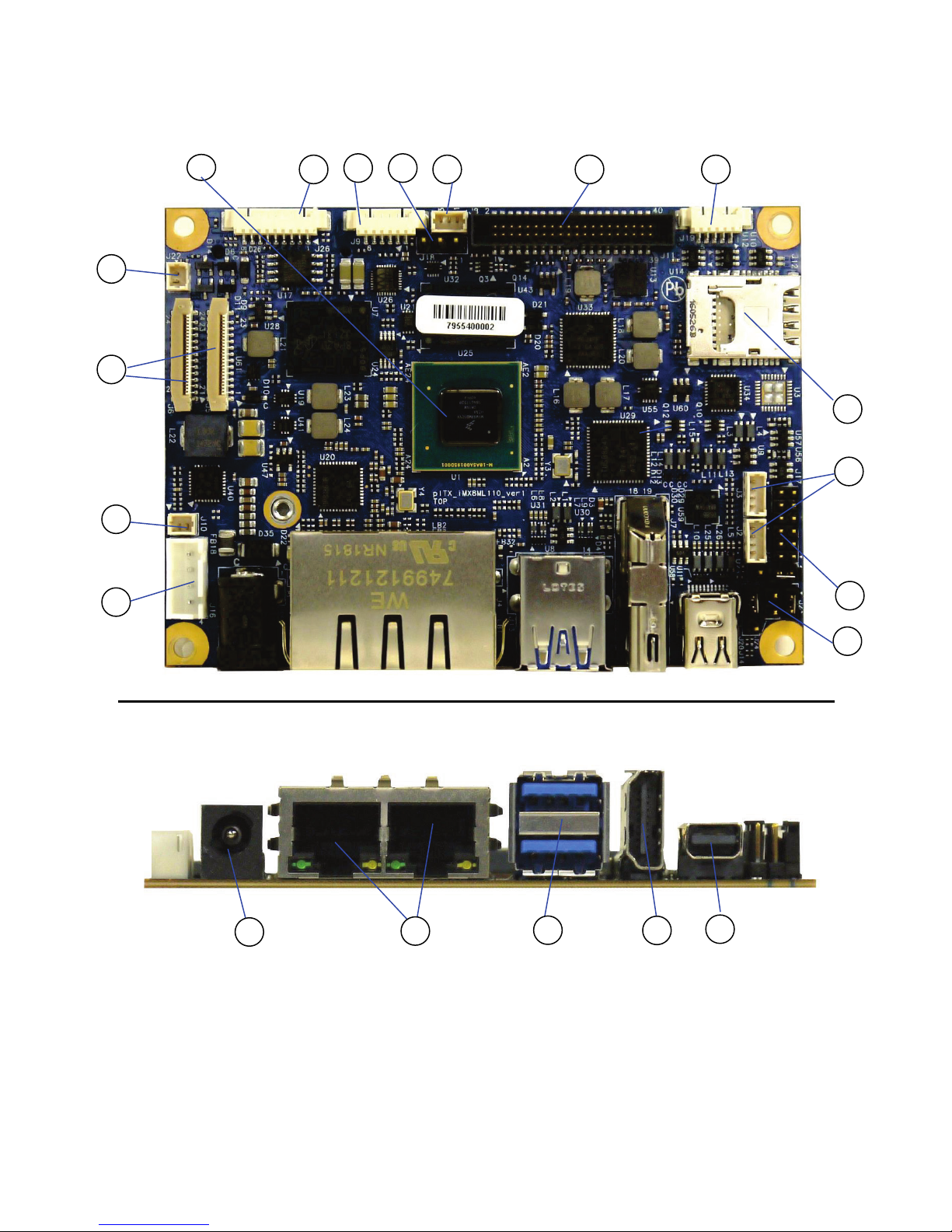
Figure 3: Front Side and Interfaces
1
2
6 5
10
9
8
7
4
20
19 18
17
3
11
16
12 13
14 15
Page 22

pITX-iMX8M – Rev. 0.1 Preliminary
www.kontron.com // 22
1
CPU
2 SPI header
3 Internal Audio Header (J26)
4 LVDS Voltage Jumper (J18)
5 Fan connector (J8)
6 LVDS connector (J11)
7 RS232 connector (J19)
8 SIM card connector (J12)
9 USB internal connector (J2, J3)
10 GPIO connector (J17)
11 Jumper (J24, J20, J23)
12 Internal DC Power connector (J16)
13 SPDIF header (J10)
14 2x Camera connector (J5, J6)
15 Pigtail battery header (J22)
16 DC Power Jack
17 2x Ethernet
18 2x USB 3.0
19 HDMI
20 Mini DP
Page 23

pITX-iMX8M – Rev. 0.1 Preliminary
www.kontron.com // 23
5.2.1. Rear Side
Figure 4: Rear Side
21 M.2 connector
21
Page 24

pITX-iMX8M – Rev. 0.1 Preliminary
www.kontron.com // 24
Figure 5: System parts with integrated premounted cooler
Page 25

pITX-iMX8M – Rev. 0.1 Preliminary
www.kontron.com // 25
6/ Pin Definitions
The following sections provide pin definitions and detailed description of all on-board connectors.
The connector definitions follow the following notation:
Table 5: Connector Definitions
Column Name Description
Pin Shows the pin-numbers in the connector. The graphical layout of the connector definition
tables is made similar to the physical connectors.
Signal The mnemonic name of the signal at the current pin.
The notation “XX#” states that the signal “XX” is active low.
Type AI: Analog Input.
AO: Analog Output.
I: Input, TTL compatible if nothing else stated.
IO: Input / Output. TTL compatible if nothing else stated.
IOT: Bi-directional tristate IO pin.
IS: Schmitt-trigger input, TTL compatible.
IOC: Input / open-collector Output, TTL compatible.
IOD: Input / Output, CMOS level Schmitt-triggered. (Open drain output)
NC: Pin not connected.
O: Output, TTL compatible.
OC: Output, open-collector or open-drain, TTL compatible.
OT: Output with tri-state capability, TTL compatible.
LVDS: Low Voltage Differential Signal.
PWR: Power supply or ground reference pins.
Ioh: Typical current in mA flowing out of an output pin through a grounded load,
while the output voltage is > 2.4 V DC (if nothing else stated).
Iol: Typical current in mA flowing into an output pin from a VCC connected load,
while the output voltage is < 0.4 V DC (if nothing else stated).
Pull U/D On-board pull-up or pull-down resistors on input pins or open-collector output pins.
Note Special remarks concerning the signal.
Designation Type and number of item described
see Section Number of section in this manual containing detailed description
Page 26

pITX-iMX8M – Rev. 0.1 Preliminary
www.kontron.com // 26
6.1. Processor Support
The i.MX 8M family of application processors based on Arm® Cortex®-A53 and Cortex-M4 cores provide audio, voice
and video processing for applications that scale from consumer home audio to industrial building automation and
mobile computers. The processors offer:
Video quality with full 4K UltraHD resolution and HDR (Dolby Vision, HDR10 and HLG)
High levels of pro audio fidelity with more than 20 audio channels, each with 384 KHz
DSD512 audio capability
Optimized for fanless operation, low thermal system cost, and long battery life
17 x 17 mm, 0.65 mm pitch, FBGA
The pITX-iMX8M supports the listed embedded SKUs:
i.MX 8M QuadLite (1.3 GHz/Industry)
i.MX 8M QuadLite (1.5 GHz/Consumer)
i.MX 8M Dual (1.3 GHz/Industry)
i.MX 8M Dual (1.5 GHz/Consumer)
Kontron has defined the board versions as listed in the following table, so far all based on Embedded CPUs.
Table 6: Processor Support
Name Speed (GHz) Cache Tj Cores
i.MX 8M QuadLite 1.3 1 MB unified L2 cache -40 to +105 °C 4
i.MX 8M QuadLite 1.5 1 MB unified L2 cache 0 ºC to 95 ºC 4
i.MX 8M Dual 1.3 1 MB unified L2 cache -40 to +105 °C 2
i.MX 8M Dual 1.5 1 MB unified L2 cache 0 ºC to 95 ºC 2
Page 27

pITX-iMX8M – Rev. 0.1 Preliminary
www.kontron.com // 27
Figure 6: Block Diagram i.MX8M processor (Source: NXP)
6.2. System Memory Support
The pITX-iMX8M board supports a 32-bit DRAM interface LPDDR4 memory interface. The integrated memory
controller can support memory speeds up to 3200 MT/s. Maximum memory supported is 4GB.
If using 32 Bit OS, less than 4 GB are displayed in the system (Shared Video Memory/PCI
resources are subtracted).
Page 28

pITX-iMX8M – Rev. 0.1 Preliminary
www.kontron.com // 28
6.3. MicroSD and MicroSIM (J12)
The pITX-iMX8M board supports micro SD cards via micro SD/micro SIM combo connector.
Figure 7: Combo Connector for MicroSD and MicroSIM
Table 7: Pin Assignment MicroSIM
Pin Type
1 V_VCC
2 RST
3 CLK_S3
4 RSVD_S4
5 GND_S5
6 V_VPP
7 I/O
8 RSVD_S8
Table 8: Pin Assignment MicroSD
Pin Type
1 DAT2
2 CD/DAT3
3 CMD
4 V_VDD
5 CLK_T5
6 VSS/GND
7 DAT0
8 DAT8
SW CARD_DETECT
Page 29

pITX-iMX8M – Rev. 0.1 Preliminary
www.kontron.com // 29
6.4. Ethernet Connectors (I/O area)
The pITX-iMX8M supports two channels of 10/100/1000 Mbit/s Ethernet (LAN1 to LAN2).
In order to achieve the specified performance of the Ethernet port, Category 5 twisted pair cables must be used with
10/100 MByte/s and Category 5E, 6 or 6E with 1 Gbit/s LAN networks.
Figure 8: Ethernet Connector RJ-45 Jack with Integrated Magnetic
Table 9: Pin Assignment
Pin Signal
Ethernet 10
BaseT/100BaseT
Gigabit-Ethernet
1 MDI0+ TX+ D1+
2 MDI0- TX- D1-
3 MDI1+ RX+ D2+
4 MDI1- D3+
5 MDI2+ D3-
6 MDI2- RX- D2-
7 MDI3+ D4+
8 MDI3- D4-
Table 10: Signal Description
Signal Description
MDI[0]+ / MDI[0]- In MDI mode, this is the first pair in 1000Base-T, i.e. the BI_DA+/- pair,
and is the transmit pair in 10Base-T and 100Base-TX.
In MDI crossover mode, this pair acts as the BI_DB+/- pair,
and is the receive pair in 10Base-T and 100Base-TX.
MDI[1]+ / MDI[1]- In MDI mode, this is the second pair in 1000Base-T, i.e. the BI_DB+/- pair,
and is the receive pair in 10Base-T and 100Base-TX.
In MDI crossover mode, this pair acts as the BI_DA+/- pair,
and is the transmit pair in 10Base-T and 100Base-TX.
MDI[2]+ / MDI[2]- In MDI mode, this is the third pair in 1000Base-T, i.e. the BI_DC+/- pair.
In MDI crossover mode, this pair acts as the BI_DD+/- pair.
MDI[3]+ / MDI[3]- In MDI mode, this is the fourth pair in 1000Base-T, i.e. the BI_DD+/- pair.
In MDI crossover mode, this pair acts as the BI_DC+/- pair.
8 7 6 5 4 3 2 1
LED status:
Orange
- 1000 Mbit/s link
established
Green
- 100 Mbit/s link
established
Off
- 10 Mbit/s Link
established
LED status:
Off
– Link is down
Flash
ing Green: Link is up
and active
Steady Green:
Link is up,
no activity
Page 30

pITX-iMX8M – Rev. 0.1 Preliminary
www.kontron.com // 30
6.5. USB Connectors (I/O area)
pITX-iMX8M board supports a dual-stacked USB3.0 interface with 5 Gbps speed. The following connections are
available for the USB 3.0:
1x Dual-stacked USB3.0 Type A at rear I/O
1x M.2 B-key half-size connector
Additionally there is a 1x Dual internal USB2.0 header.
Figure 9: USB 2.0/3.0 socket
USB 2.0 USB 3.0
Table 11: Pin Assignment
Pin Type Signal Note
1 PWR GND USB2.0 / 3.0
2 IO USB n+ USB2.0 / 3.0
3 IO USB n- USB2.0 / 3.0
4 PWR 5 V/SB 5 V USB2.0 / 3.0
5 IO TXn+ USB3.0
6 IO TXn- USB3.0
7 PWR GND USB3.0
8 IO RXn+ USB3.0
9 IO RXn- USB3.0
Table 12: Signal Description
Signal Description
USBn+ USBnRXn+ RXnTXn+ TXn-
Differential pair works as serial differential receive/transmit data lines.
Change to: USB2.0 (n=0,1,2,3), USB3.0 (n=0,1)
5 V / SB5 V
5 V supply for external devices.
SB5 V is supplied during power-down to allow wakeup on USB device activity.
Protected by a 2A current limiting IC (1A for each port).
For USB2.0 cabling it is required to use only HiSpeed USB cable, specified in USB2.0 standard:
1
2 3
4
1 2 3 4
9 8 7 6 5
Page 31
pITX-iMX8M – Rev. 0.1 Preliminary
www.kontron.com // 31
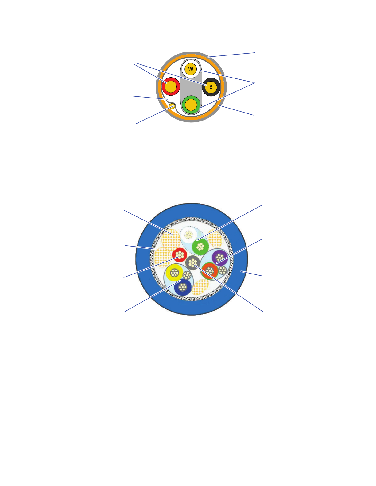
Figure 10: USB 2.0 High Speed Cable
For USB3.0 cabling it is required to use only HiSpeed USB cable, specified in USB3.0 standard:
Figure 11: USB 3.0 High Speed Cable
W
G
BR
Polyvinyl Chloride (PVC) Jacket
Outer Shield ≥
65% Interwoven
Tinned Copp
er Braid
Inner Shield Aluminum
Metallized Polyester
28 AWG Tinned Copper Drain Wire
T
wisted Signaling Pair:
White: D
- Green: D+
On-
Twisted Power Pair:
Red: V
BUS
Black: Power Ground
UTP Signal Pair
SDP Signal Pair
Jacket
Ground
Filler, optional
Braid
Power
SDP Signal Pair
Page 32

pITX-iMX8M – Rev. 0.1 Preliminary
www.kontron.com // 32
6.6. Fan Connector (internal, J8)
The Fan can be used to actively cool the heatsink mounted on the board. The fan rotation speed can be monitored
and the fan speed controlled by the temperature of the PCB (near SoC).
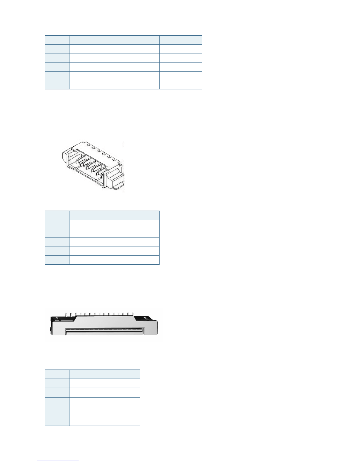
Figure 12: 3-pin Fan Connector
Table 13: 3-pin Mode
Pin Signal Description Type
1
TACHO Rotation speed I
2
PWM PWM output O-5V
3
GND
Ground
PWR
Table 14: Signal Description
Signal Description
GND Power Supply GND signal
TACHO Tacho input signal from the fan, for rotation speed supervision RPM (Rotations
Per Minute).
PWM Output signal for FAN speed control.
1
Page 33

pITX-iMX8M – Rev. 0.1 Preliminary
www.kontron.com // 33
6.7. DC Power Jack Connector (5 Vin Ext., J15)
Figure 13: Power Jack Connector
Either the DC Power Jack Connector (5 Vin Ext.) or the “5 Vin Int.” connector must be used to supply the board with
+5V +/-5 %.
The 5 Vin Ext. power connector has Vin to the center pin and mates with Ø 6.3 mm DC Power jack with Ø 2.0 mm pin
hole. (DC Connector RA 2 mm locking type). Maximum allowed current is 5 A.
The board can be supplied via the AC/DC adapter plugged into the power jack. Such adapters
have usually no connection to protective earth. Consequently, the potential of the
conductive parts on the board may drift. If a human touches such a part, this may lead to an
electric shock. The board must be grounded separately, if the unit is supplied via power jack.
Hot Plugging power supply is not supported.
Hot plugging might damage the board.
To protect the external power lines of peripheral devices make sure that
the wires have the right diameter to withstand the maximum available current.
to enclosure of the peripheral device fulfills the fire-protecting conditions of
IEC/EN 60950.
Page 34

pITX-iMX8M – Rev. 0.1 Preliminary
www.kontron.com // 34
6.8. Pigtail Battery Header (J22)
Figure 14: Pigtail Battery Header
Table 15: Pin Assignment
Pin Signal
1 V_BAT
2 GND
6.9. Internal Power Connector (Vin Int., J16)
Figure 15: Internal Power Connector
Table 16: Internal Power Connector
Header Pin Signal Description
1 +5V +5V power input PWR
2 +5V +5V power input PWR
3 GND Power Ground PWR
4 GND Power Ground PWR
Maximum allowed current on each pin is 3A.
1
1
Page 35

pITX-iMX8M – Rev. 0.1 Preliminary
www.kontron.com // 35
6.10. USB internal (J2, J3)
Figure 16: USB Internal Connector
Table 17: USB Internal Connection
Pin Description Pin Description
1 GND 2 USB_Pn+
3 USB_Pn- 4 5 V/SB 5 V
6.11. GPIO Connector (internal, J17)
Figure 17: GPIO Connector
Table 18: GPIO Connector
Pin Description Pin Description
1 V_3V3_S5 2 FGPIO0
3 FGPIO1 4 FGPIO2
5 FGPIO3 6 FGPIO4
7 FGPIO5 8 FGPIO6
9 FGPIO7 10 GND
11 GND 12 EXT_BAT
1
1
Page 36

pITX-iMX8M – Rev. 0.1 Preliminary
www.kontron.com // 36
6.12. Jumper Internal Boot (J21)
Figure 18: Jumper Internal Boot
Table 19: Jumper Internal Boot
Pin Description
1 SCU_BOOT_MODE0
2 SCU_BOOT_MODE1
3 GND
Function:
Pin 1-2: Internal Boot [Default]
Pin 2-3: Boot From Fuse
6.13. Jumper Autostart/Always ON (J20)
Figure 19: Always ON
Table 20: Always ON Internal Connection
Pin Description
1 NC
2 AUTOSTART#
3 GND
Function:
Pin1-2: Off
Pin2-3: Always ON (Default)
1
1
Page 37

pITX-iMX8M – Rev. 0.1 Preliminary
www.kontron.com // 37
6.14. Jumper LVDS Panel Voltage (J18)
Figure 20: LVDS Panel Voltage
Table 21: LVDS Panel Voltage
Pin Description
1 V_5V0_S0
2 V_5V0_3V3_JP
3 V_3V3_S0
Function:
Pin1-2: 5V LVDS Panel Voltage
Pin2-3: 3.3V LVDS Panel Voltage (Default
6.15. LVDS (internal, J11)
Figure 21: LVDS Connector
Table 22: LVDS Pin Assignment
Pin Description Pin Description
1 5 V 2 5 V
3 5 V 4 5 V
5 5 V 6 GND
7 5 V 8 GND
9 V_LVDS 10 V_LVDS
11 I2C1_SCL_3V3_LVDS 12 I2C1_SDA_3V3_LVDS
13 LVDS_BL_PWM 14 LVDS_VDD_EN_3V3
15 LVDS_BL_EN 16 GND
1
Page 38

pITX-iMX8M – Rev. 0.1 Preliminary
www.kontron.com // 38
Pin Description Pin Description
17 LVDS_A_DATA0- 18 LVDS_A_DATA_A0+
19 LVDS_A_DATA1- 20 LVDS_A_DATA_A1+
21 LVDS_A_DATA2- 22 LVDS_A_DATA_A2+
23 LVDS_A_CLK- 24 LVDS_A_CLK+
25 LVDS_A_DATA3- 26 LVDS_A_DATA3+
27 GND 28 GND
29 LVDS_B_DATA0- 30 LVDS_B_DATA_A0+
31 LVDS_B_DATA1- 32 LVDS_B_DATA1+
33 LVDS_B_DATA2- 34 LVDS_B_DATA2+
35 LVDS_B_CLK- 36 LVDS_B_CLK+
37 LVDS_B_DATA3- 38 LVDS_B_DATA3+
39 GND 40 GND
6.16. HDMI connector (J7)
Figure 22: 19-pin HDMI connector
Pin Signal
1
TMDS Data2+
2
TMDS Data2 Shield
3
TMDS Data2−
4
TMDS Data1+
5
TMDS Data1 Shield
6
TMDS Data1−
7
TMDS Data0+
8
TMDS Data0 Shield
9
TMDS Data0−
10
TMDS Clock+
11
TMDS Clock Shield
12
TMDS Clock-
13
CEC
14
Reserved / Utility
15
SCL
16
SDA
17
DDC/CEC Ground
Page 39

pITX-iMX8M – Rev. 0.1 Preliminary
www.kontron.com // 39
Pin Signal
18 +5V Power
19 Hot Plug Detect
6.17. Mini Display Port (J14)
The two external Display Port 1.2 at rear I/O space are supporting Active/Passive HDMI 1.4a and DVI adapters.
Figure 23: Mini Display Port
Table 23: Mini Display Port
Pin Signal Description
1 GND Ground
2
Hot Plug Detect
Hot Plug Detect
3
ML_Lane 0 +
Lane 0 (positive)
4 CONFIG1 CONFIG1
5
ML_Lane 0 -
Lane 0 (negative)
6 CONFIG2 CONFIG2
7 GND Ground
8 GND Ground
9
ML_Lane 1 +
Lane 1 (positive)
10
ML_Lane 3 +
Lane 3 (positive)
11
ML_Lane 1 -
Lane 1 (negative)
12
ML_Lane 3 -
Lane 3 (negative)
13 GND Ground
14 GND Ground
15
ML_Lane 2 +
Lane 2 (positive)
16
AUX_CH (p)
Auxiliary Channel (positive)
17
ML_Lane 2 -
Lane 2 (negative)
18
AUX_CH -
Auxiliary Channel (negative)
19 GND Ground
20 DP_PWR Power for connecto
1
Page 40

pITX-iMX8M – Rev. 0.1 Preliminary
www.kontron.com // 40
6.18. SPDIF Internal Audio Header (J9)
Figure 24: SPDIF Internal Header
Table 24: Pin Assignment J9
Pin Signal
1 LINE_OUT_R_C
2 GND
3 LINE_OUT_L_C
4 LINE_IN_R_C
5 MIC_IN_C
6 LINE_IN_L_C
6.19. M.2 Connector (mPCIe/mSATA) (J1)
The Slot connector has two functions: mSATA or miniPCIe. The Slot connector detects the
mounted card technology with autosensing. So there is no need for further configuration.
Figure 25: M.2 Connector (mPCIe)
Table 25: Pin Assignment
Pin Signal Type
1 WAKE#
2 +3V3 PWR
3 NC NC
4 GND PWR
5 NC NC
1
1
Page 41

pITX-iMX8M – Rev. 0.1 Preliminary
www.kontron.com // 41
Pin Signal Type
6 +1.5V PWR
7 CLKREQ#
8 UIM_PWR PWR
9 GND PWR
10 UIM_DATA NC
11 PCIE_mini CLK#
12 UIM_CLK NC
13 PCIE_mini CLK
14 UIM_RESET NC
15 GND PWR
16 UIM_VPP NC
17 UIM_IC_DM NC
18 GND PWR
19 UIM_IC_DP
20 W_Disable#
21 GND PWR
22 RST#
23 PCIE_RX-/SATA_RX-
24 +3V3 PWR
25 PCIE_RX+/SATA_RX+
26 GND PWR
27 GND PWR
28 +1.5 V PWR
29 GND PWR
30 SMB_CLK
31 PCIE_TX-/SATA_TX-
32 SMB_DATA
33 PCIE_TX+/SATA_TX+
34 GND PWR
35 GND PWR
36 USBhub_D1_N IO
37 GND PWR
38 USBhub_D1_P IO
39 +3V3 PWR
40 GND PWR
41 +3V3 PWR
42 NC NC
43 SATA_DET5#
44 NC NC
45 NC NC
46 NC NC
47 NC NC
Page 42
pITX-iMX8M – Rev. 0.1 Preliminary
www.kontron.com // 42
Pin Signal Type
48 +1.5 V PWR
49 NC NC
50 GND PWR
51 NC NC
52 +3V3 PWR
6.20. Serial COM (J19)
Figure 26: Serial COM
Table 26: Pin Assignment
Pin Signal
1 RS232_TXD
2 RS232_RXD
3 RS232_RTS#
4 RS232_CTS#
5 GND
6.21. Camera connector (J5, J6)
Figure 27: 24-pin Camera CSI Connector
Table 27: Pin Assignment (J5)
Pin Signal
1 NC
2
CKV_2V8_CAM1_S0
3
CSI0_RX0-
4 NC
5
CSI0_RX0+
1
1
Page 43

pITX-iMX8M – Rev. 0.1 Preliminary
www.kontron.com // 43
Pin Signal
6
NC
7 CSI0_CLK-
8
NC
9
CSI0_CLK+
10 GND
11 CSI0_RX1-
12
CAM_XCLK_1V8_CAM1
13
CSI0_RX1+
14
V_1V8_S0
15
V_1V5_CAM
16
NC
17
CSIO_P1_PWDN_1V8
18
NC
19
CAM_RST_1V8#
20
I2C1_SCL_1V8_CAM1
21
V_2V8_CAM
22
I2C1_SDA_1V8_CAM1
23
GND
24
NC
Table 28: Pin Assignment (J6)
Pin Signal
1 NC
2
2V8_CAM
3
CSI2_RX0-
4 NC
5
CSI2_RX0+
6
NC
7 CSI2_CLK-
8
NC
9
CSI2_CLK+
10 GND
11 CSI2_RX1-
12
CAM_XCLK_1V8_CAM2
13
CSI2_RX1+
14
V_1V8_S0
15
V_1V5_CAM
16
NC
17
CSI_P2_PWDN_1V8
18
NC
Page 44

pITX-iMX8M – Rev. 0.1 Preliminary
www.kontron.com // 44
Pin Signal
19
CAM_RST_1V8#
20
I2C3_SCL_1V8_CAM2
21
V_2V8_CAM2
22
I2C3_SDA_1V8_CAM2
23
GND
24
NC
Page 45

pITX-iMX8M – Rev. 0.1 Preliminary
www.kontron.com // 45
7/ uEFI BIOS
7.1. Starting the uEFI BIOS
The pITX-iMX8M is provided with a Kontron-customized, pre-installed and configured version of American
Megatrends, Inc. (AMI). It is based on the Unified Extensible Firmware Interface (uEFI) specification and the Intel®
Platform Innovation Framework for EFI. This uEFI BIOS provides a variety of new and enhanced functions specifically
tailored to the hardware features of the pITX-iMX8M.
The BIOS version covered in this document might not be the latest version. The latest
version might have certain differences to the BIOS options and features described in this
chapter.
The uEFI BIOS comes with a Setup program which provides quick and easy access to the individual function settings
for control or modification of the uEFI BIOS configuration. The Setup program allows the accessing of various menus
which provide functions or access to sub-menus with more specific functions of their own.
To start the uEFI BIOS Setup program, follow the steps below:
1. Power on the board.
2. Wait until the first characters appear on the screen (POST messages or splash screen).
3. Press the <DEL> key.
4. If the uEFI BIOS is password-protected, a request for password will appear. Enter either the User Password or
the Supervisor Password (see Security menu), press <RETURN>, and proceed with step 5.
5. A Setup menu will appear.
The pITX-iMX8M uEFI BIOS Setup program uses a hot key-based navigation system. A hot key legend bar is located
on the bottom of the Setup screens.
The following table provides information concerning the usage of these hot keys.
Table
29: Navigation Hot Keys Available in the Legend Bar
Hotkeys Description
<F1> The <F1> key is used to invoke the General Help window.
<-> The<Minus> key is used to select the next lower value within a field.
<+> The <Plus> key is used to select the next higher value within a field.
<F4> The <F4> key is used to Exit saving Changes.
<F3> The <F3> key is used to load Optimized Defaults.
<→> or <←>
The <Left/Right> arrows are used to select major Setup menus on the menu bar.
For example: Main screen, Advanced screen, Security screen, etc.
<↑> or <↓>
The <Up/Down> arrows are used to select fields in the current menu.
For example a Setup function or a sub-screen.
<ESC> The <ESC> key is used to exit a Setup menu.
<ENTER> The <ENTER> key is used to execute a command or select a submenu.
Page 46

pITX-iMX8M – Rev. 0.1 Preliminary
www.kontron.com // 46
7.2. Setup Menus
The Setup utility features a selection bar at the top of the screen that lists the available menus:
1. Main
2. Advanced
3. Chipset
4. Security
5. Boot
6. Save & Exit
The currently active menu and the currently active uEFI BIOS Setup item are highlighted in white. Use the left and
right arrow keys to select the Setup menus.
Each Setup menu provides two main frames. The left frame displays all available functions. Configurable functions
are displayed in blue. Functions displayed in black provide information about the status or the operational
configuration. The right frame displays a Help window providing an explanation of the respective function.
7.2.1. Main Setup Menu
On entering the uEFI BIOS, the Setup program displays the Main Setup menu. This screen lists basic system and
board information.
Figure 28: Main Setup Menu Initial Screen
The following table shows Main sub-screens and functions, and describes the content. Default settings are in
bold
.
Page 47

pITX-iMX8M – Rev. 0.1 Preliminary
www.kontron.com // 47
Table 30: Main Setup Menu Sub-screens
Sub-Screen Function Second level Sub-Screen / Description
BIOS
Information
Read only field
Displays BIOS Information
Board Vendor, BIOS Version, Build Date and Time, Access Level
Board
Information
Read only field
Displays Board Information
Manufacturer, Product Name, PCB Version, Serial Number, Part Number, Boot Count
On-board
LAN
Information
Read only field
Displays LAN MAC Address
CPU
Information
Read only field
Displays CPU Information
Memory
Information
Read only field
Displays Memory Information
Platform
firmware
Information
Read only field
Displays Platform firmware Information
System
Date>
Sets the system date
[mm/dd/yyyy]
System
Time>
Sets the system time
[hh:mm:ss]
Page 48

pITX-iMX8M – Rev. 0.1 Preliminary
www.kontron.com // 48
7.2.2. Advanced Setup Menu
The Advanced Setup menu provides sub-screens and second level sub-screens with functions, for advanced
configuration and Kontron specific configurations.
Setting items, on this screen, to incorrect values may cause system malfunctions.
Figure 29: Advanced Setup Menu Initial Screen
The following table shows the Advanced sub-screens and functions and describes the content. Default settings are
in
bold
and some functions include additional information. The function / submenu in italic indicate either status
display or submenu string that cannot be selected. The underlined statement indicates the condition for the
availability of the second-level submenu in reference to submenu.
Page 49

pITX-iMX8M – Rev. 0.1 Preliminary
www.kontron.com // 49
Table 31: Advanced Setup menu Sub-screens and Functions
Sub-Screen Function Second level Sub-Screen / Description
Driver
Health
Intel® PRO/1000 7.0.06 PCI-E
Trusted
Computing
TPM20 Device Status,
Vendor and Firmware
Version.
Security Device Support
[Enable]
When set to Enable:
Active PCR banks
Available PCR banks
SHA-1 PCR Bank
[Enabled]
SHA256 PCR Bank
[Enabled]
Pending operation
[None]
Platform Hierarchy
[Enabled]
Storage Hierarchy
[Enabled]
Endorsement Hierarchy
[Enabled]
TPM2.0 UEFI Spec Version
[TCG_2]
Physical Presence Spec Version
[1.3]
TPM 20 InterfaceType [TIS]
Device Select
[Auto]
ACPI
Settings
Enable ACPI Auto
Configuration
(Disabled)
When set to Disable:
Enable Hibernation
[Enabled]
ACPI Sleep State
[S3 (Suspend to RAM)]
Lock Legacy Resources
[Disabled]
SMART
Settings
SMART Self Test
[Disabled]
Serial Port
Console
Redirection
Console Redirection
(COM0) >
[Disabled]
When set to Enabled:
COM# Console Redirection Settings
[ANSI]
Bits per second
[115200]
Data Bits
[None]
Stop Bits
[1]
Flow Control
[None]
VT-UTF8 Combo Key Support
[Enabled]
Recorder Mode
[Disabled]
Resolution 100x31
[Disabled]
Legacy OS Redirection Resolution
[80x24]
Putty KeyPad
[VT100]
Redirection After BIOS POST
[Always Enable]
Legacy Console
Redirection Settings >
Legacy Serial Redirection Port [COM0]
Serial Port for Out-ofBand Management /
Windows Emergency
Management Services
(EMS)
Console Redirection >
[Disabled]
When set to Enabled:
Console Redirection Settings >
Out-of-Band Mgmt Port [COM0]
Terminal Type
[VT-UTF8]
Bits per second
[115200]
Flow Control
[None]
Data Bits
[8]
Page 50

pITX-iMX8M – Rev. 0.1 Preliminary
www.kontron.com // 50
Sub-Screen Function Second level Sub-Screen / Description
Parity
[None]
Stop Bits
[1]
CPU
Configurati
on
Turbo Mode
[Enabled]
Intel Virtualization Technology
[Enabled]
VT-d
[Disabled]
Monitor Mwait
[Disabled]
AMI Graphic
Output
Control
Policy
Intel ® Graphics Controller
Intel ® GOP Driver
Output select
[DP1]
PCI
Subsystem
Settings
AMI PCI Driver Version
Above 4G Decoding
[Disabled]
Hot-Plug Support
[Enabled]
Network
Stack
Configurati
on
Network Stack
[Disabled]
CSM
Configurati
on
CSM Support
[Enabled]
When set to Enabled:
CSM16 Module Version 07.79
GateA20 Active
[Upon Request]
INT19 Trap Response
[Immediate]
Boot option filter
[UEFI and Legacy]
Option ROM execution
Network
[UEFI]
Storage
[UEFI]
Video
[UEFI]
Other PCI devices
[UEFI]
NVMe
Configurati
on
NVME controller and Drive information
SDIO
Configurati
on
SDIO Access Mode
[Auto]
Mass Storage Devices:
USB
Configurati
on
Legacy USB Support
[Enabled]
XHCI Hand-off
[Enabled]
USB Mass Storage Driver Support
[Enabled]
USB transfer time-out
[20 sec]
Device reset time-out
[20 sec]
Device power-up delay
[Auto]
Security
Configurati
on
TXE HMRFPO
[Disabled]
TXE EOP Message
[Enabled]
Page 51

pITX-iMX8M – Rev. 0.1 Preliminary
www.kontron.com // 51
Sub-Screen Function Second level Sub-Screen / Description
LVDS
Configurati
on
LVDS Flat Panel Display
Support
[Disabled]
When set to Enabled:
Panel Type
[Standard]
Resolution
[1024 x 768]
Panel Color Depth
[24-Bit VESA]
Panel Voltage
[3.3V]
Channel
[Dual]
Bus Swapping
[Normal]
Clock Frequency Center Spread
[Disabled]
Differential Output Swing Level
[300 mV]
Backlight
[Enable]
Backlight Signal Inversion
[Disable]
Backlight PWM Frequency
[200 Hz]
Brightness Level
[80%]
Hardware
Monitor
Hardware Monitoring:
CPU DTS Temperature (CPU MSR)
PCB Temperature (TD1)
NCT7802Y Temperature (LTD)
LM75B Temperature (I2C0)
NCT7802Y Voltage (VCC)
RTC Voltage (VCORE)
DDR Voltage (VSENS2)
Input Voltage (VSENS3)
CPU Fan:
CPU Fan Pulse
CPU Fan Control Mode
[SMART FAN IV]
Fan Trip Point
Trip Point Speed
CPLD
Configurati
on
Serial Port 0
[Enabled]
When set to Enabled:
Base Address
[3E8]
IRQ
[10]
GPIO IRQ
[Disabled]
I2C IRQ
[Disabled]
Watchdog
Auto-reload
[Disabled]
Global Lock
[Disabled]
Stage 1 mode
[Disabled]
Thermal
Automatic Thermal
Reporting
[Disabled]
When set to Disabled:
Critical Trip Point
[125 C]
Passive Trip Point
[95 C]
Passive TC1 value 1
Passive TC2 value 5
Passive TSP value 10
System
Component
OS Reset Select
[Cold Reset]
Spread Spectrum Clocking Configuration
DDR SSC
[Enable]
When set to Enable:
DDR SSC Selection Table
[-0.5%]
Page 52

pITX-iMX8M – Rev. 0.1 Preliminary
www.kontron.com // 52
Sub-Screen Function Second level Sub-Screen / Description
DDR SSC Bending Selection Table
[0% (No Clock Bending)]
HighSpeed SerialIO SSC
[Enable]
When set to Enable:
HighSpeed SerialIO SSC Selection Table
[-0.5%]
Debug
Configurati
on
Kernel Debugger Configuration
Kernel Debugger Enable
[Disabled]
APEI BERT Configuration
APEI BERT
[Enable]
ACPI Memory Debug
Switch
ACPI Memory Debug
[Disable]
TXE Debug Option
End of Post
[Disable]
Lock Directory
[Disable]
PTT Debug Option
Suppress PTT
Commands
[Disable]
TDO GPIO Pin Switch
TDO GPIO Pin
[Enable]
Max Memory 2G
[Disable]
Persistent RAM Size
[Disable]
OS DnX
OS DnX focus entry
[Disable]
Processor Trace Configuration
Processor Trace memory allocation
[Disable]
CSE Data Clear Option
CSE Data Clear (Yes /
No)
Option to clear Data region during IFWI Update
Capsule Data Clear
[Enable]
NPK Debug Configuration >
North Peak Enable
[Auto]
FW Trace Enable
[Enable]
FW Trace Destination
[PTI]
NPK Recovery Dump
[Disable]
Memory Region 0 Buffer Size
[None]
Memory Region 0 Buffer WrapAround
[Wrap]
Memory Region 1 Buffer Size
[None]
Memory Region 1 Buffer WrapAround
[Wrap]
PTI Mode
[X4]
PTI Training
[Off]
PTI Speed
[Quarter Speed]
Page 53

pITX-iMX8M – Rev. 0.1 Preliminary
www.kontron.com // 53
Sub-Screen Function Second level Sub-Screen / Description
Punit Message Level
[LEVEL LOW]
PMC Message Level
[LEVEL LOW]
RC ACPI
Settings
Native PCIE Enable
[Enable]
Native ASPM
[Enable]
RTD3
Settings
RTD3 Support
[Disable]
7.2.3. Chipset Setup Menu
The Chipset Setup menu provides sub-screens, second level and third level sub-screens with functions, for Intel
Chipset configurations.
Figure 30: Chipset Setup Menu Initial Screen
Table 32: Chipset Setup menu Sub-screens and Functions
Sub-Screen Function Second level Sub-Screen / Description
North Bridge Max TOLUD
[2 GB]
PCIE VGA Workaround
[Disable]
South Bridge Serial IRQ Mode
[Continuous]
SMBus Support
[Enabled]
Page 54

pITX-iMX8M – Rev. 0.1 Preliminary
www.kontron.com // 54
Sub-Screen Function Second level Sub-Screen / Description
OS Selection
[Windows 10 (Ver>=167)]
PCI Clock Run
[Enable]
Real Time Option
[RT Disable]
Uncore
Configuration
GOP Configuration
GOP Driver
[Enable]
Intel Graphics Pei Display PEIM
[Disable]
GOP Brightness Level [140]
IGD Configuration
Integrated Graphics Device
[Enable]
Primary Display
[IGD]
RC6 (Render Standby)
[Disable]
GTT Size
[8MB]
Aperture Size
[256MB]
DVMT Pre-Allocated
[64M]
DVMT Total Gfx Mem
[256M]
Cd Clock Frequency
[624 MHz]
GT PM Support
[Enable]
PAVP Enable [Enable]
IGD – LCD Control
BIA
[Auto]
ALS Support
[Enable]
IGD Flat Panel
[Auto]
IGD Boot Type
[Auto]
Panel scaling
[Auto]
GMCH BLC Control [PWM-Inverted]
South Cluster
Configuration
HD-Audio Configuration >
HD-Audio Support [Enable]
LPSS Configuration >
Low Power Sub System
LPSS HSUART
#3 Support (D24:F2)
[Enable]
LPSS SPI #1
Support (D25:F0)
[Enable]
LPSS IOSF PMCTL SOix Enable [Enable]
PCI Express Configuration >
PCI Express Configuration
PCI Express Clock Gating [Enable]
Port8xh Decode [Disable]
Peer Memory Write Enable [Disable]
Compliance Mode [Disable]
>
PCIe #0 BDF[00:13:00] LAN 1
> PCIe #1 BDF[00:13:01] mPC
Ie
When PCIE #X is enabled:
PCIe #X BDF[XX:XX:XX] [Auto]
ASPM [Disable]
L1 Substates [L1.1 & L1.2]
ACS
[Enable]
URR
[Disable]
FER
[Disable]
NFER
[Disable]
CER
[Disable]
CTO
[Default Setting]
SEFE
[Disable]
SENFE
[Disable]
SECE
[Disable]
PME SCI
[Enable]
Hot Plug
[Disable]
PCIE Speed [Auto]
Transmitter Half Swing
[Disable]
Extra Bus Reserved 0
Reserved Memory 10
Reserved I/O 4
Page 55

pITX-iMX8M – Rev. 0.1 Preliminary
www.kontron.com // 55
Sub-Screen Function Second level Sub-Screen / Description
PCH PCIE LTR [Enable]
Snoop Latency Override
[Auto]
Non Snoop Latency Override
[Auto]
PCIE LTR Lock [Disable]
PCIE Selectable De
-emphasis
[Enable]
SATA Drives >
SATA Drives
Chipset
-SATA Controller Configuration
SATA Port 0
Port 0 [Enable]
SATA Port 0 Hot Plug Capability [Disable]
SATA Port 1 (mSATA)
Port 0 [Enable]
SATA Port 0 Hot Plug Capability [Disable]
SCC Configuration >
SCC SD Card Support (D27:F0) [Enable]
USB Configuration >
USB Port Disable Override [Disable]
XHCI Disable Compliance Mode [FALSE]
Miscellaneous Configuration >
State After G3 [S0 State]
Power Button De
bounce Mode
[Enable]
Wake on LAN [Disable]
BIOS Lock [Disable]
RTC Lock [Enable]
TCO Lock [Disable]
DCI Enable (HDCIEN) [Disable]
DCI Auto Detect Enable [Enable]
GPIO Lock [Disable]
Page 56

pITX-iMX8M – Rev. 0.1 Preliminary
www.kontron.com // 56
7.2.4. Security Setup Menu
The Security Setup menu provides information about the passwords and functions for specifying the security
settings. The passwords are case-sensitive.
Figure 31: Security Setup Menu Initial Screen
The following table shows Security sub-screens and functions.
Table 33: Security Setup Menu Functions
Function Description
Setup Administrator Password
User Password
Create / change password to enter Setup
HDD Security Configuration Create / change password to allow access to Set, Modify and
Clear HardDisk User and Master Passwords for Enabling Security.
Attempt Secure Boot
[Disable]
Enable or Disable the Secure Boot support.
Please also set Secure Boot Mode to “Standard” to install
standard Microsoft Platform Key (PK).
Secure Boot Mode
Set Secure Boot Mode to “Standard” to boot standard Windows or
Linux boot loader signed with Microsoft’s platform key. Select
“Customized” mode only if you have a custom OS with OS boot
loader signed with your own platform key. Kontron provide
services for Customized Secure Boot, visit Kontron SEC-Line home
Page 57
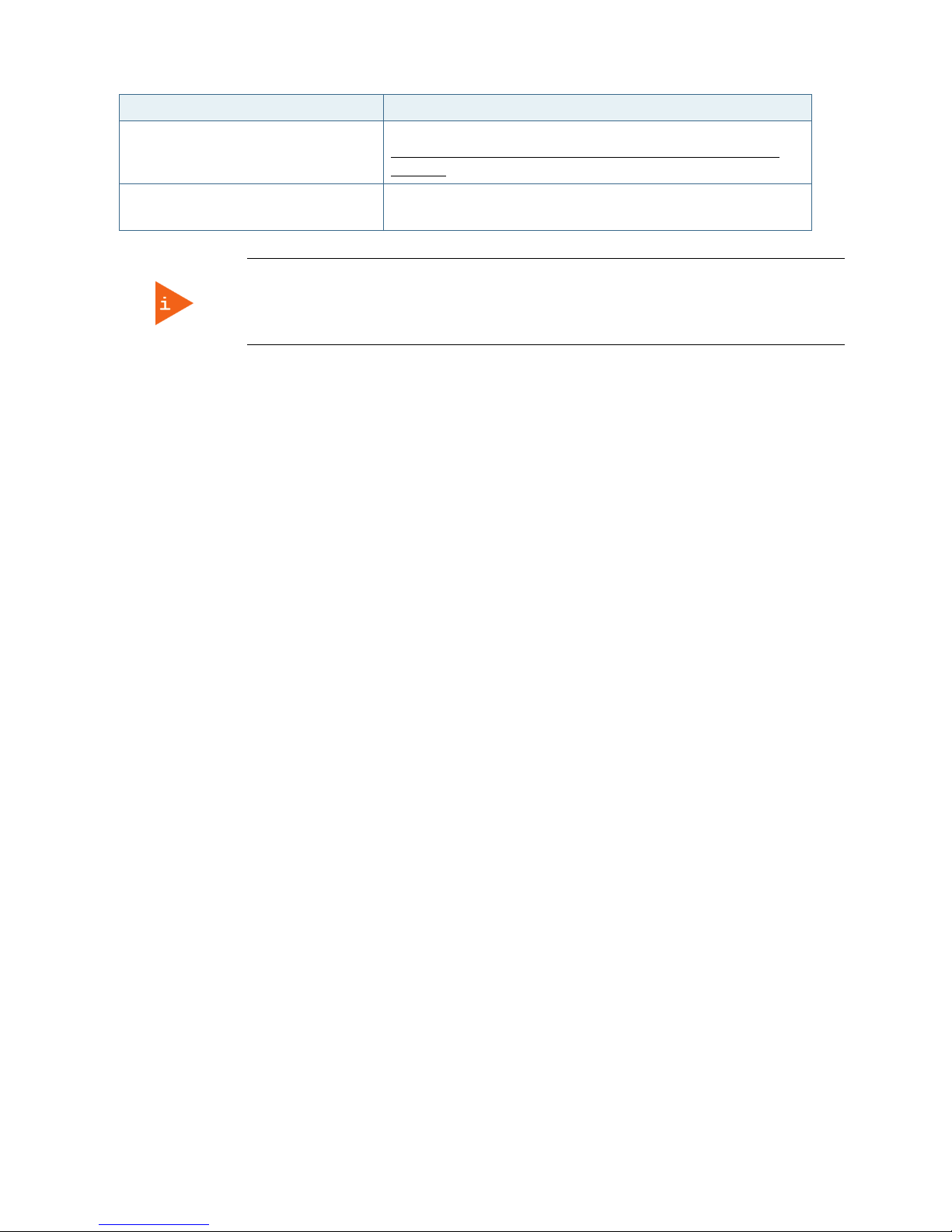
pITX-iMX8M – Rev. 0.1 Preliminary
www.kontron.com // 57
Function Description
page
https://www.kontron.com/products/solutions/security/secline.html for more information.
Key Management Enables expert users to modify Secure Boot Policy Variables
without full authentication.
If only the administrator’s password is set, then only access to the setup is limited and is
requested when entering the setup.
If the user’s password is set, then the password is a power on password and must be
entered to boot or enter setup. In the setup the user has restricted rights.
7.2.4.1. Remember the Password
It is highly recommended to keep a record of all passwords in a safe place. Forgotten passwords result in the user
being locked out of the system.
If the system cannot be booted because the User Password or the Supervisor Password are not known, contact
Kontron Support for further assistance.
Page 58

pITX-iMX8M – Rev. 0.1 Preliminary
www.kontron.com // 58
7.2.5. Boot Setup Menu
The Boot Setup menu lists dynamically generated boot device priority order.
Figure 32: Boot Setup Menu Initial Screen
The following table shows Boot sub-screens and functions, and describes the content. Default settings are in
bold
.
Table 34: Boot Setup Menu Functions
Function Description
Boot Configuration
Setup Prompt Timeout 1
Bootup NumLock State
[On]
Quiet Boot
[Enabled]
Boot Option Priorities
Boot Option #1
Boot Option #2
Boot Option #3
Boot Option #4
Fast Boot
[Enable]
SATA Support
VGA Support
USB Support
To set the system boot order. Use +/- keys to change option.
When Fast Boot is Enabled, SATA, VGA, USB, PS2 support, devices
initialization, Network Stack driver can be customized.
Page 59

pITX-iMX8M – Rev. 0.1 Preliminary
www.kontron.com // 59
Function Description
PS2 Support
Network Stack Driver Support
Redirection Support
New Boot Option Policy Controls the placement of newly detected UEFI boot options
Hard Drive BBS Priotities Sets the placement of legacy boot options
Page 60

pITX-iMX8M – Rev. 0.1 Preliminary
www.kontron.com // 60
7.2.6. Exit Setup Menu
The Save and Exit Setup menu provides functions for handling changes made to the uEFI BIOS settings and exiting
the Setup program.
If system cannot boot or work properly due to incorrect setting, shorting Pin-1 and Pin-2 on
J15 jumper will load the default setting of BIOS upon power cycle. Once safely booted with
default setting, you may undo the jumper setting to save new changes on BIOS Setup Menu.
Figure 33: Save and Exit Setup Menu Initial Screen
The following table shows the Exit menu sub-screens and functions, and describes the content.
Table 35: Save and Exit Setup Menu Functions
Function Description
Save Options
Save Changes and Exit
Discard Changes and Exit
Save Changes and Reset
Discard Changes and Reset
Default Options
Restore Defaults
Save as User Defaults
Page 61

pITX-iMX8M – Rev. 0.1 Preliminary
www.kontron.com // 61
Function Description
Restore User Defaults
Boot Override
UEFI: Built-in EFI Shell
Launce EFI Shell from filesystem
device
7.3. The uEFI Shell
The Kontron uEFI BIOS features a built-in and enhanced version of the uEFI Shell. For a detailed description of the
available standard shell scripting, refer to the EFI Shell User Guide. For a detailed description of the available
standard shell commands, refer to the EFI Shell Command Manual. Both documents can be downloaded from the EFI
and Framework Open Source Community homepage (http://sourceforge.net/projects/efi-shell/files/documents/).
Kontron uEFI BIOS does not provide all shell commands described in the EFI Shell Command
Manual. If Secure Boot is enabled, the UEFI shell may not be able to be entered.
7.3.1. Basic Operation of the uEFI Shell
7.3.1.1. Entering the uEFI Shell
To enter the uEFI Shell, follow the steps below:
1. Power on the board.
2. Press the <F7> key (instead of <DEL>) to display a choice of boot devices.
3. Choose ‘UEFI: Built-in EFI Shell’.
EFI Shell version 2.50 [5.12]
Current running mode 1.1.2
Device mapping table
fs0 :Removable HardDisk – Alias hd18c0b blk0
PciRoot(0x0)/Pci(0x15,0x0)/USB(0x2,0x0)/HD(1,MBR,0x0002B27D,0x3F,0x785BEC)
blk0 :Removable HardDisk – Alias hd18c0b fs0
PciRoot(0x0)/Pci(0x15,0x0)/USB(0x2,0x0)/HD(1,MBR,0x0002B27D,0x3F,0x785BEC)
blk1 :Removable BlockDevice – Alias (null)
PciRoot(0x0)/Pci(0x15,0x0)/USB(0x2,0x0)
Press the ESC key within 5 seconds to skip startup.nsh, and any other key to continue.
4. The output produced by the device-mapping table can vary depending on the board’s configuration.
5. If the ESC key is pressed before the 5 second timeout elapses, the shell prompt is shown:
Shell>
7.3.1.2. Exiting the uEFI Shell
To exit the uEFI Shell, follow one of the steps below:
1. Use the exit uEFI Shell command to select the boot device, in the Boot menu, that the OS will boot from.
2. Reset the board using the reset uEFI Shell command.
Page 62

pITX-iMX8M – Rev. 0.1 Preliminary
www.kontron.com // 62
7.4. uEFI Shell Scripting
7.4.1. Startup Scripting
If the ESC key is not pressed and the timeout has run out then the uEFI Shell tries to execute some startup scripts
automatically. It searches for scripts and executes them in the following order:
1. Initially searches for Kontron flash-stored startup script.
2. If there is no Kontron flash-stored startup script present then the uEFI-specified startup.nsh script is used.
This script must be located on the root of any of the attached FAT formatted disk drive.
3. If none of the startup scripts are present or the startup script terminates then the default boot order is
continued.
7.4.2. Create a Startup Script
Startup scripts can be created using the uEFI Shell built-in editor edit or under any OS with a plain text editor of your
choice. To create a startup shell script, simply save the script on the root of any FAT-formatted drive attached to the
system.
7.4.3. Examples of Startup Scripts
7.4.3.1. Execute Shell Script on other Harddrive
This example (startup.nsh) executes the shell script named bootme.nsh located in the root of the first detected disc
drive (fs0).
fs0:
bootme.nsh
7.5. Firmware Update
Firmware updates are typically delivered as a ZIP archive containing only the firmware images. The content of the
archive with the directory structure must be copied onto a data storage device with FAT partition.
7.5.1. Updating Procedure
BIOS can be updated with the Intel tool fpt64.efi using the procedure below:
1. Copy these files to an USB stick.
flash.nsh or flash_with_fpt.nsh (if available)
fpt.efi
fparts.txt
pITX_IMX8M_BIOS_Ver_<xxx>……bin (where xxx stands for the version #)
2. Start the system into the uEFI shell (see chapter 7.3.1.1 “Entering the uEFI Shell”).
3. Change to the drive representing the USB stick.
fsx: (x = 0,1,2,etc. represents the USB stick)
Change to the directory where you copied the flash tool.
cd <your_directory>
4. Start flash.nsh or flash_with_fpt.nsh (if available)
Page 63

pITX-iMX8M – Rev. 0.1 Preliminary
www.kontron.com // 63
OR type
fpt –y –f pITX_IMX8M_BIOS_Ver_<xxx>……bin
5. Wait until flashing is successful and then power cycle the board.
Do not switch off the power during the flash process!
Page 64

pITX-iMX8M – Rev. 0.1 Preliminary
www.kontron.com // 64
List of Acronyms
DP
Display Port
DVI
Digital Video Interface
EDP
Embedded DisplayPort
EMI
Electromagnetic Interference
ESD
Electrostatic Discharge
FCBGA
Flip Chip Ball Grid Array
FWH
Firmware Hub
HDMI
High Definition Multimedia Interface
LPC
Low Pin Count
LVDS
Low Voltage Differential Signaling
MPCIE
Mini PCI Express
MSATA
Mini Serial ATA
PCBA
Printed Circuit Board Assembly
PEG
PCI Express Graphics
RTC
Real Time Clock
SATA
Serial ATA
SDVO
Serial Digital Video Out
SMBUS
System Management Bus
SOC
System on Chip
SPI
Serial Peripheral Interface
TPM
Trusted Platform Module
ULV
Ultra-low Voltage
USB
Universal Serial Bus
Page 65

www.kontron.com // 65
About Kontron
Kontron, a global leader in embedded computing technology and trusted advisor in Internet of Things (IoT), works
closely with its customers, allowing them to focus on their core competencies by offering a complete and integrated
portfolio of hardware, software and services designed to help them make the most of their applications.
With a significant percentage of employees in research and development, Kontron creates many of the standards
that drive the world’s embedded computing platforms; bringing to life numerous technologies and applications that
touch millions of lives. The result is an accelerated time-to-market, reduced total-cost-of-ownership, product
longevity and the best possible overall application with leading-edge, highest reliability embedded technology.
For more information, please visit: http://www.kontron.com/
Headquarters
Kontron
S&T AG
Lise
-Meitner-Str. 3-5
86156 Augsburg
Germany
Tel.: +
49 821 4086-0
Fax: +
49 821 4086-111
info@kontron.com
 Loading...