

Page 1
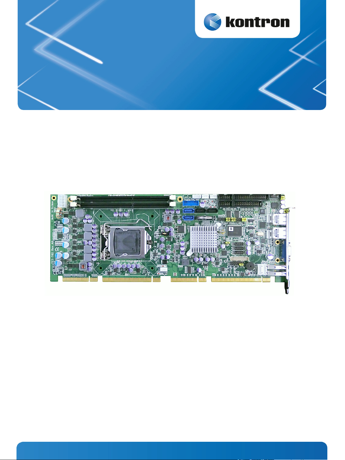
PCI-762
» User Guide «
User’s Guide (Version 1.0)
1055-9117
www.kontron.com
Page 2

This page is intentionally left blank.
www.kontron.com
Page 3

1. Table of Contents PCI 762 – User’s Guide (Version 1.0)
1. Table of Contents
1. Table of Contents ................................................................................................................................... 1
2. Introduction ......................................................................................................................................... 4
2.1. Symbols used in this Manual .................................................................................................................... 5
3. Safety Instructions ................................................................................................................................ 6
3.1. Safety Instructions for the Lithium Battery ................................................................................................. 6
3.2. Basic Safety and EMC Compatibility ........................................................................................................... 6
4. Important Instructions ........................................................................................................................... 7
4.1. Electrostatic Discharge (ESD) .................................................................................................................. 7
4.2. Note on the Warranty ............................................................................................................................ 7
4.3. Exclusion of Accident Liability Obligation ................................................................................................... 7
4.4. Liability Limitation / Exemption from the Warranty Obligation ........................................................................ 7
4.5. General Instruction on Usage .................................................................................................................. 7
5. Scope of Delivery ................................................................................................................................... 8
5.1. Labeling Information ............................................................................................................................ 8
6. Product Description................................................................................................................................ 9
6.1. I/O Bracket ......................................................................................................................................... 9
7. Features ............................................................................................................................................. 10
8. Main Specifications .............................................................................................................................. 12
8.1. Electrical Specifications ....................................................................................................................... 12
8.2. Environmental Specifications ................................................................................................................ 12
8.3. CE Directives ...................................................................................................................................... 12
8.4. Mechanical Specifications ..................................................................................................................... 13
8.4.1. Board Dimensions ........................................................................................................................ 13
9. Jumpers and Connectors ....................................................................................................................... 14
9.1. Board Layout ..................................................................................................................................... 14
9.2. Jumper Settings ................................................................................................................................. 15
9.2.1. COM1 Mode Select Jumpers for RS-232/422/485 (JP3, JP4, JP5) ............................................................ 15
9.2.2. Audio Amplifier Jumper (JP1) ......................................................................................................... 16
9.2.3. Clear RTC Jumper (JP8) .................................................................................................................. 16
9.3. Connectors ........................................................................................................................................ 17
9.3.1. SMBUS Connector (CN1) ................................................................................................................ 18
9.3.2. Floppy Disk Port Connector (CN4) ..................................................................................................... 19
9.3.3. Internal USB Connectors (CN5) ....................................................................................................... 20
9.3.4. Internal USB Connectors (CN8, CN10, CN13) ....................................................................................... 20
9.3.5. LAN2 LED Connectors (CN6) ............................................................................................................ 21
9.3.6. LAN1 LED Connectors (CN7) ............................................................................................................ 21
9.3.7. DB15 CRT Connector (CN11) Co-layout with CN12 ................................................................................. 21
9.3.8. DVI-D Pin Header (CN14) ............................................................................................................... 22
9.3.9. Front Panel Connector (CN15) ......................................................................................................... 23
9.3.10. PS/2 Keyboard, Mouse Connectors (CN17, CN18) ............................................................................... 24
www.kontron.com 1
Page 4

1. Table of Contents PCI 762 – User’s Guide (Version 1.0)
9.3.11. External USB 3.0 Port Connectors (CN16, CN19) ................................................................................. 24
9.3.12. RS232/422/485 Pin Assignment (COM1) .......................................................................................... 25
9.3.13. COM Port RS-232 Pin Assignment (COM2) .......................................................................................... 26
9.3.14. Intel® HD Audio Digital Header (AUDIO1) ......................................................................................... 26
9.3.15. ATX 8 Pin 12V IN Connector (ATX2) .................................................................................................. 27
9.3.16. A CPU fan is always needed for cooling CPU heat (FAN3) ....................................................................... 27
9.3.17. System & Auxiliary Fan Connectors (FAN1, FAN2) ............................................................................... 27
9.3.18. Ethernet RJ-45 Connectors (LAN1, LAN2) ......................................................................................... 28
9.3.19. Parallel Port Connector (PRINT1) Print Port Connector ......................................................................... 29
9.3.20. SATA Connectors (SATA1[3.0], SATA2[3.0], SATA3, SATA4) .................................................................. 30
10. Lithium Battery ................................................................................................................................ 31
10.1. Replacing the Lithium Battery .............................................................................................................. 31
11. Hardware Description ......................................................................................................................... 32
11.1. Processors ....................................................................................................................................... 32
11.2. BIOS ............................................................................................................................................... 32
11.3. System Memory ................................................................................................................................. 32
11.4. Hardware Installation......................................................................................................................... 33
11.4.1. Installing the Processor ................................................................................................................ 33
11.5. Installing the Memory ........................................................................................................................ 38
12. AMI BIOS Utility ................................................................................................................................ 39
12.1. Starting .......................................................................................................................................... 39
12.2. Navigation Keys ................................................................................................................................ 39
12.3. Main Menu ....................................................................................................................................... 40
12.4. Advanced Menu ................................................................................................................................. 41
12.4.1. ACPI Settings ............................................................................................................................. 42
12.4.2. Trusted Computing ...................................................................................................................... 43
12.4.3. CPU Configuration ....................................................................................................................... 44
12.4.4. SATA Configuration ..................................................................................................................... 45
12.4.5. PCH-FW Configuration .................................................................................................................. 46
12.4.6. AMT Configuration ....................................................................................................................... 47
12.4.7. USB Configuration....................................................................................................................... 48
12.4.8. Super IO Configuration ................................................................................................................. 49
12.4.9. H/W Monitor .............................................................................................................................. 50
12.4.10. Intel RC Drivers Version Detail ...................................................................................................... 51
12.5. Chipset Menu .................................................................................................................................... 52
12.5.1. PCH-IO Configuration ................................................................................................................... 53
12.5.2. System Agent (SA) Configuration .................................................................................................... 54
Boot Menu ............................................................................................................................................... 55
12.6. Security Menu ................................................................................................................................... 56
12.7. Save & Exit Menu ............................................................................................................................... 57
13. Watchdog Timer ................................................................................................................................ 59
13.1. Watchdog Timer Setting ...................................................................................................................... 59
14. PCI IRQ Routing ................................................................................................................................. 61
14.1. PICMG PCI IRQ Routing ....................................................................................................................... 61
2 www.kontron.com
Page 5

1. Table of Contents PCI 762 – User’s Guide (Version 1.0)
15. Configuring SATA for RAID ................................................................................................................... 62
15.1. Configuring SATA Hard Drive(s) for RAID Function (Controller: Intel® Q77) ..................................................... 62
16. iAMT Settings .................................................................................................................................... 73
16.1. Entering MEBx .................................................................................................................................. 73
16.2. Set & Change Password ...................................................................................................................... 74
16.3. Intel® iAMT Settings ........................................................................................................................... 76
16.4. iAMT Web Console ............................................................................................................................. 80
17. Technical Support............................................................................................................................... 82
17.1. Returning Defective Merchandise .......................................................................................................... 82
www.kontron.com 3
Page 6

2. Introduction PCI 762 – User’s Guide (Version 1.0)
2. Introduction
Kontron Embedded Computers would like to point out that the information contained in this manual may be subject to
technical alteration, particularly as a result of the constant upgrading of Kontron Embedded Computers products. The
attached documentation does not entail any guarantee on the part of Kontron Embedded Computers with respect to
technical processes described in the manual or any product characteristics set out in the manual. Kontron Embedded
Computers does not accept any liability for any printing errors or other inaccuracies in the manual unless it can be proven
that Kontron Embedded Computers is aware of such errors or inaccuracies or that Kontron Embedded Computers is unaware
of these as a result of gross negligence and Kontron Embedded Computers has failed to eliminate these errors or
inaccuracies for this reason. Kontron Embedded Computers expressly informs the user that this manual only contains a
general description of technical processes and instructions which may not be applicable in every individual case. In cases
of doubt, please contact Kontron Embedded Computers.
This manual is protected by copyright. All rights are reserved by Kontron Embedded Computers. Copies of all or part of this
manual or translations into a different language may only be made with the prior written consent of Kontron Embedded
Computers. Kontron Embedded Computers points out that the information contained in this manual is constantly being
updated in line with the technical alterations and improvements made by Kontron Embedded Computers to the products
and thus this manual only reflects the technical status of the products by Kontron Embedded Computers at the time of
printing.
© 2013 by Kontron Embedded Computers
Printing and duplication, even of sections, is only permissible with the express approval of
Kontron Embedded Computers GmbH
Oskar-von-Miller-Str. 1
85386 Eching near Munich
Germany
4 www.kontron.com
Page 7
2. Introduction PCI 762 – User’s Guide (Version 1.0)
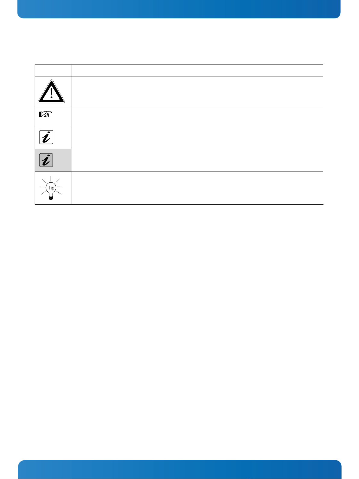
2.1. Symbols used in this Manual
Symbol Meaning
This symbol indicates the danger of injury to the user or the risk of damage to the product if the
corresponding warning notices are not observed.
This symbol indicates that the product or parts thereof may be damaged if the corresponding warning
notices are not observed.
This symbol indicates general information about the product and the user manual.
This symbol indicates detail information about the specific product configuration.
This symbol precedes helpful hints and tips for daily use.
www.kontron.com 5
Page 8
3. Safety Instructions PCI 762 – User’s Guide (Version 1.0)
3. Safety Instructions
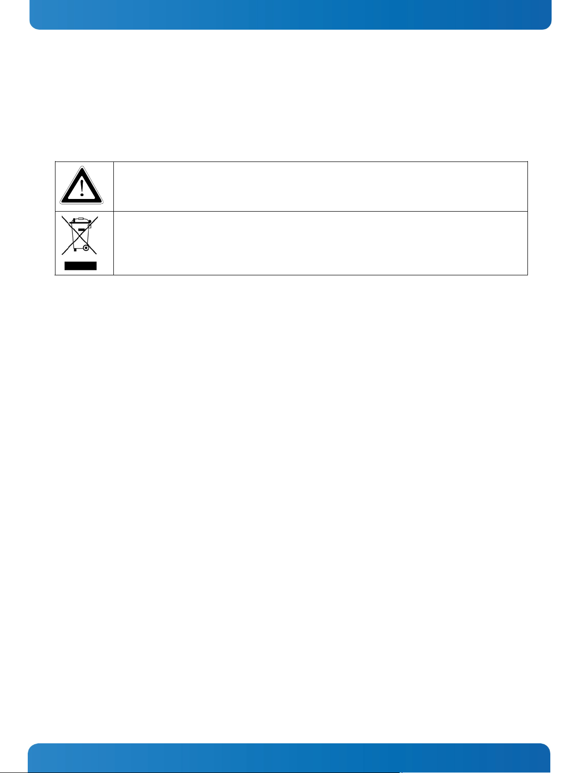
3.1. Safety Instructions for the Lithium Battery
The PCI-762 board is equipped with a Lithium battery. For the replacing of this battery please observe the instructions
described in the chapter 10.1 “Replacing the Lithium Battery”.
Caution!
Danger of explosion when replaced with wrong type of battery. Replace the battery only with
UL recognized Lithium battery that has the same or equivalent type recommended by Kontron.
Do not dispose of lithium batteries in domestic waste. Dispose of the battery according to the local
regulations dealing with the disposal of these special materials (e.g. to the collecting points for the
disposal of batteries).
3.2. Basic Safety and EMC Compatibility
The PCI-762 board is a fixed component that shall be installed into a stationary system by applying good engineering
practices and respecting the information on the intended use of the components with a view to meeting the protection
requirements [refer to (a) and (b)].
The PCI-762 board was designed and manufactured, having regard to the state of the art, as to ensure that:
(a) the electromagnetic disturbance generated does not exceed the level above which radio and telecommunications
equipment or other equipment cannot operate as intended;
(b) it has a level of immunity to the electromagnetic disturbance to be expected in its intended use which allows it to
operate without unacceptable degradation of its intended use.
The PCI-762 board was designed, manufactured and checked according to the basic safety requirements in the scope of the
low-voltage (LVD) directive.
6 www.kontron.com
Page 9

4. Important Instructions PCI 762 – User’s Guide (Version 1.0)
4. Important Instructions
The manufacturer’s instructions provide useful information on your PCI-762 board.
4.1. Electrostatic Discharge (ESD)
The components on the board are sensitive to static electricity. Care must therefore be exercised at all times during
handling and inspection of the PCI-762 board, in order to ensure the product integrity.
Do not handle this product while it is outside its protective enclosure, while it is not used for operational purposes,
unless it is otherwise anti-static protected.
Unpack or install this product only at EOS/ESD safe workstations. When safe work station are not guaranteed, it is
important for the user to be electrically discharged before touching the PCI-762 board with his/her hands or tools. This
is most easily done by touching a metal part of your system housing.
Only hold the assemblies at the edge.
Do not touch any connection pins or conductors on the assembly.
4.2. Note on the Warranty
Due to their limited service life, parts which, by their nature, are especially subject to wear (wearing parts) are not included
in the guarantee beyond the legal stipulations. This applies to the batteries, for example.
4.3. Exclusion of Accident Liability Obligation
Kontron Embedded Computers shall be exempted from the statutory accident liability obligation if the user fails to observe
the safety instructions.
4.4. Liability Limitation / Exemption from the Warranty Obligation
In the event of damage to the device caused by failure to observe the hints in this manual and eventually on the device
(especially the safety instructions), Kontron Embedded Computers shall not be required to honor the warranty even during
the warranty period and shall be exempted from the statutory accident liability obligation.
4.5. General Instruction on Usage
In order to ensure safe operation, the user must observe the instructions and warnings contained in this manual.
The PCI-762 board must be used in accordance with the instructions for use.
The PCI-762 board is designed to be built-in to a system, which fulfill all necessary technical and environmental
requirements.
When installing the board into a system, ensure that the system is switched off and the systems power cord is
disconnected from the power source. Disconnect all cable connections of peripheral devices from the system.
Ensure that the DC operating voltages adheres to the specification given in the section 8.1“Electrical Specifications”.
Only devices and components which fulfill the requirements of a SELV circuit (security extra low voltage) in accordance
with IEC / EN 60950-1 may be connected to the interfaces of the PCI-762 board.
If extensions are made to the PCI-762 board, the legal stipulations and the board specifications must be observed.
www.kontron.com 7
Page 10
5. Scope of Delivery PCI 762 – User’s Guide (Version 1.0)
5. Scope of Delivery
1x PCI-762 Board [PICMG 1.3 Single Board Computer (full-size)]
Driver CD
General Safety Instruction for IT Equipment
Serial Part cable
Slot Bezel with 4x USB 2.0
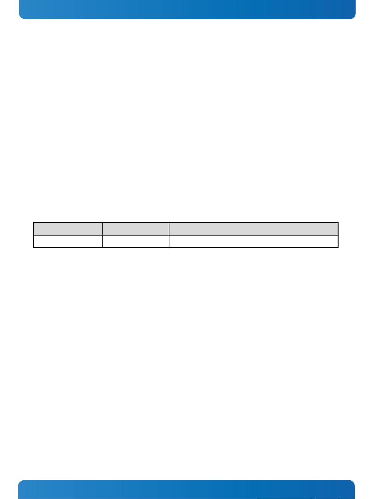
5.1. Labeling Information
Two types of printed labels on the PCI-762 board must show the following information:
1. Board identification label that has implemented: Board Designation/Serial Number/Part Number/Product
Revision/QM-Field/Bar Code/Datamatrix Code
2. MAC-Address Labels
System Type Product Designation Product Identification
PCI-762 1054-9860 MBD_PCI-762-PICMG.1.3_LGA1155_Q77
8 www.kontron.com
Page 11
6. Product Description PCI 762 – User’s Guide (Version 1.0)
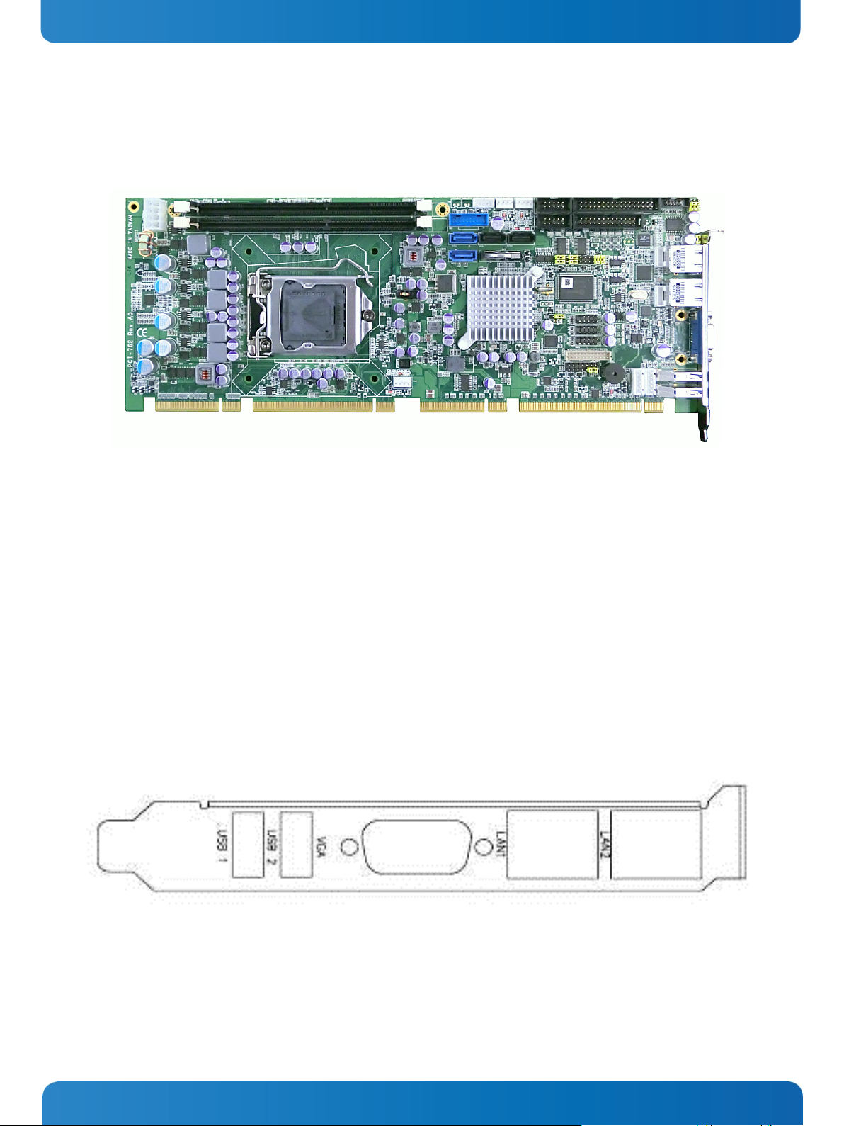
6. Product Description
The PCI-762 PICMG 1.3 full-size Single Board Computer (SBC) supports LAG1155 socket H2 for Intel® Core™ i3 Desktop
Processor, Intel® Core™ i5 Desktop Processor, Core™ i7 Desktop Processor with 32nm technology and Transfer Rate
1333/1600 MHz.
The board integrates Intel® Q77 chipset that delivers outstanding system performance through high-bandwidth
interfaces, multiple I/O functions for interactive applications and various embedded computing solutions.
There are two 240-pin DDR3 DIMM sockets for dual channel DDR3 1333/1600, maximum memory capacity up to 16GB.
The board also features dual Gigabit Ethernet, two SATA-6.0Gb/s and two SATA-3.0Gb/s and SATA RAID 0/1/5/10 by PCH.
Ten USB 2.0 & four USB 3.0 high speed compliant ports and built-in Intel® HD Audio Digital Header can achieve the best
stability and reliability for industrial applications.
6.1. I/O Bracket
www.kontron.com 9
Page 12

7. Features PCI 762 – User’s Guide (Version 1.0)
7. Features
CPU
Intel® Core™ i3 Desktop Processor
Intel® Core™ i5 Desktop Processor
Intel® Core™ i7 Desktop Processor
System Chipset
Intel
CPU Socket
LGA1155 Socket
DRAM Transfer Rate
1066/1600 MHz
BIOS
AMI BIOS via SPI interface with socket
®
Q77
System Memory
Two 240-pin DDR3 1333/1600 DIMM sockets
Maximum up to 16GB DDR3 memory
Supports DDR3 1066/1333 memory
Onboard Multi-I/O
Parallel Port: one 26-pin 2.54-pitch box-header, SPP/EPP/ECP supported
Serial Port: one for RS-232/422/485 with 10-pin, 2.54-pitch box-header (COM1) and one port for
RS-232 with 10-pin, 2.54-pitch box-header (COM2)
Floppy controller: one 34-pin, 2.54-pitch box-header supports two drives (1.44MB for each)
VGA Controller
Intel® Arrandale integrated a Graphic processing unit processor which goes with Q77 chipset with
VGA, DisplayPort (co-lay with VGA) and DVI
Memory Size - Intel
®
DVMT 5.0 supported; preallocated memory for frame buffer option as OS
option:
1. Windows XP:
* For Total System Memory < 1GB,
Graphics sharing memory = 128 MB Maximum;
* For 1 GB to 1.5 GB Total System Memory,
Graphics sharing memory = 512 MB Maximum;
* For 1.5 GB to 2 GB Total System Memory,
Graphics sharing memory = 768 MB Maximum;
* For 2 GB and Above Total System Memory,
Graphics sharing memory = 1GB Maximum.
2. Windows Vista:
* Graphics sharing memory max to 0.5* (OS Ram Size – 512)
Resolution -- Analog output -- the analog port utilizes an integrated 400MHz 24-bit RAMDAC that
can directly drive a standard progressive scan analog monitor up to a resolution of 2048x1536
pixels with 32-bit color at 75 Hz
Analog Output Interface -- CRT from DAC output via 15-pin D-Sub connector on the edge; CRT
always ON supported
10 www.kontron.com
Page 13

7. Features PCI 762 – User’s Guide (Version 1.0)
USB Interface
Ten USB ports compliant with USB Spec. Rev. 2.0 (6 ports on board, 4 ports to SHB connector-C
golden fingers)
Four USB ports compliant with USB Spec. Rev. 3.0 (2 ports on rear I/O, 2 ports on board)
Ethernet
The LAN1/LAN2 are Intel 82579LM with iAMT 7.0 / Intel 82574L Ethernet controller support
10/100/1000 Mb/s
Serial ATA
Support Serial ATA/Serial ATA II
Two Serial ATA-6Gb/s and two Serial ATA-3Gb/s performance and SATA RAID 0/1/5/10 by Q77
Audio
10-pin 2.0 pin-header (Intel
Hardware Monitoring
Monitoring temperatures, voltages, and cooling fan status
®
HD Audio Digital Header)
Watchdog Timer
Reset Supported (1-255 level)
Dimensions
338mm x 126mm
All specifications and images are subject to change without notice.
www.kontron.com 11
Page 14
8. Main Specifications PCI 762 – User’s Guide (Version 1.0)
8. Main Specifications
8.1. Electrical Specifications
Board
Version
PCI-762 ATX PSU Backplane and
Type of the external PSU Inputs via
PICMG 1.3 edge connector
On-board 12 V ATX power connector: ATX2 +12V
8.2. Environmental Specifications
Operating Temperature
Relative Humidity
0 °C to 60 °C (32 °F to 140 °F)
10 % to 90 % (non-condensing)
8.3. CE Directives
CE Directives
Electrical Safety
ElectroMagnetic Compatibility (EMC) EMC Directive 2004/108/EC
General Product Safety Directive (GPSD) 2001/95/EC
Low Voltage Directive (LVD) 2006/95/EC
+3.3 VSB, +5 VSB,
+3.3 V, +5.0 V, +12.0 V
12 www.kontron.com
Page 15
Weight
0.450 kg (0.992 lbs.) (without CPU fan)
8. Main Specifications PCI 762 – User’s Guide (Version 1.0)
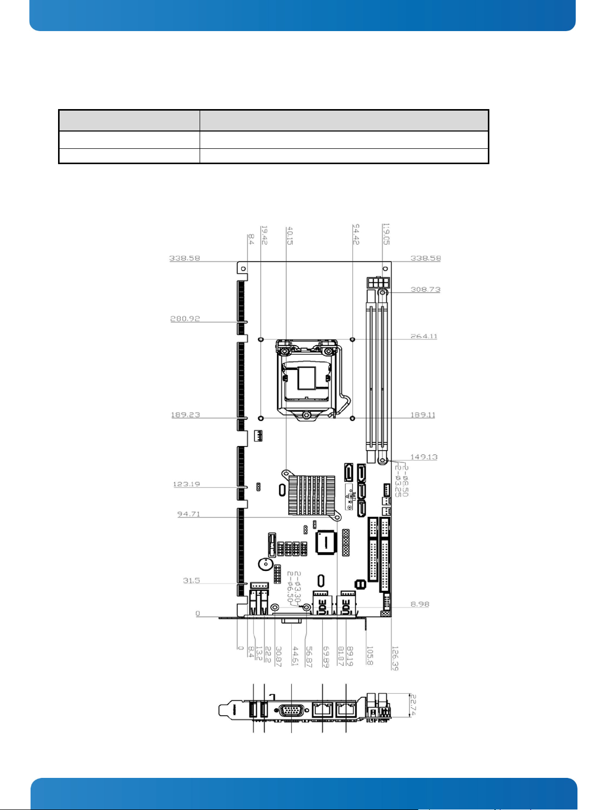
8.4. Mechanical Specifications
Dimension PCI-762
Height x Width
8.4.1. Board Dimensions
338 mm x 126 mm
www.kontron.com 13
Page 16
Lithium Battery
+
9. Jumpers and Connectors PCI 762 – User’s Guide (Version 1.0)
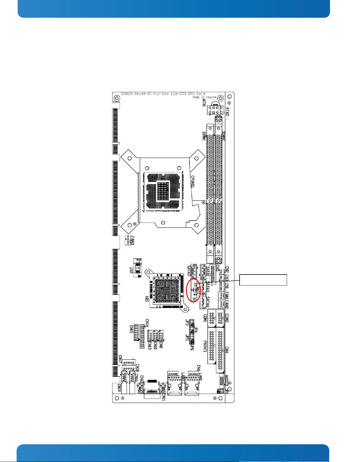
9. Jumpers and Connectors
9.1. Board Layout
14 www.kontron.com
Page 17

COM1
9. Jumpers and Connectors PCI 762 – User’s Guide (Version 1.0)
9.2. Jumper Settings
Proper jumper settings configure the PCI-762 to meet your application purpose.
Jumper Description Jumper Setting
JP3 COM1 Mode Selection : RS-232 Short 3-5 , 4-6
JP4 COM1 Mode Selection : RS-232 Short 3-5 , 4-6
JP5 COM1 Mode Selection : RS-232 Short 1-2
JP1 Audio Amplifier Selection : Disable Short 1-3 , 2-4
JP8 Clear RTC : Normal Short 1-2
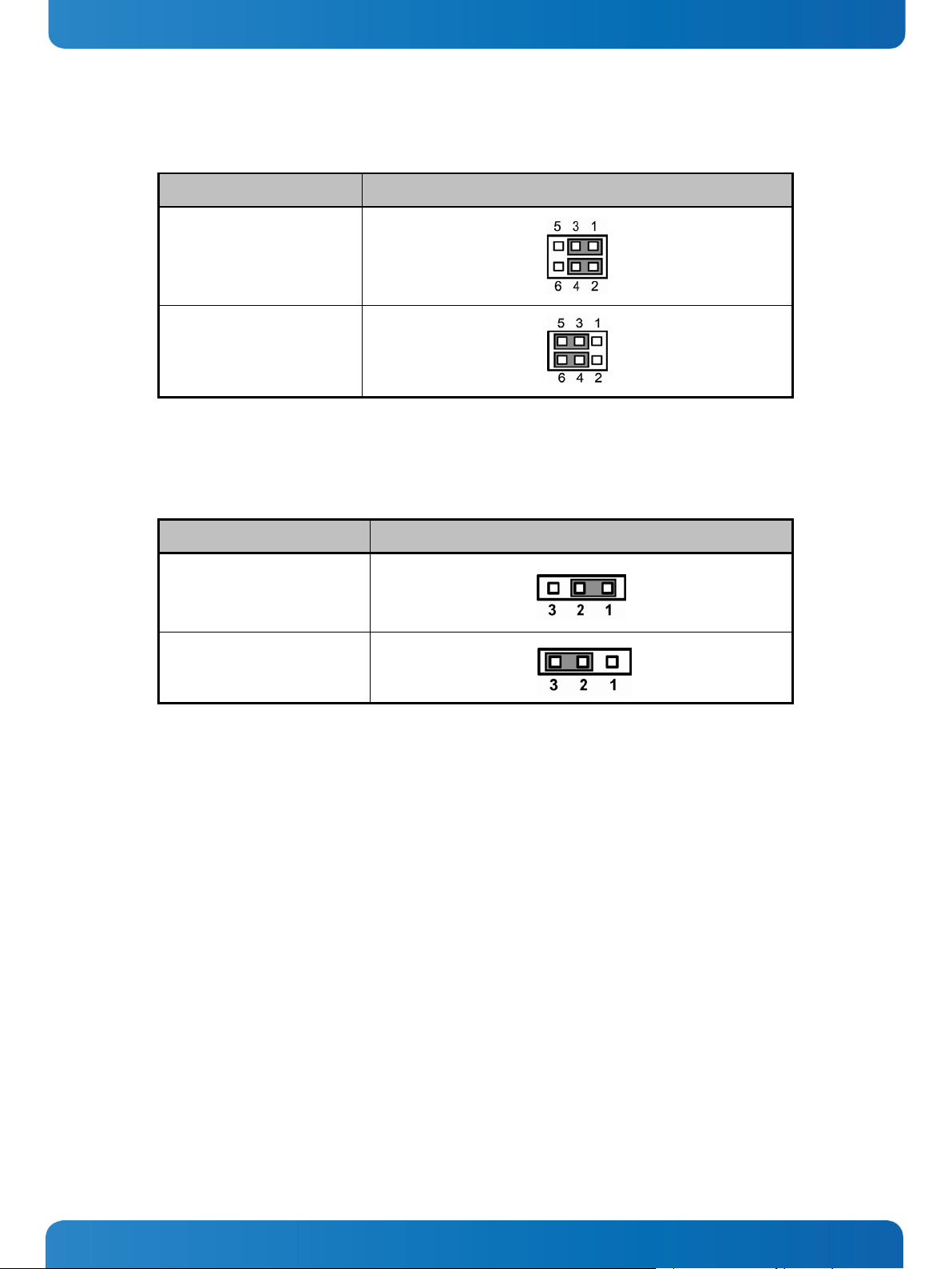
9.2.1. COM1 Mode Select Jumpers for RS-232/422/485 (JP3, JP4, JP5)
These jumpers select the COM1 port’s communication mode to operate RS-232 or RS-422/485.
Description Function Jumper Setting
RS-232 (Default)
RS-422
RS-485
JP3
JP3
JP3
JP4
JP4
JP4
JP5
JP5
JP5
www.kontron.com 15
Page 18
9. Jumpers and Connectors PCI 762 – User’s Guide (Version 1.0)
9.2.2. Audio Amplifier Jumper (JP1)
Function Jumper Setting
Disable
(Default)
Enable
9.2.3. Clear RTC Jumper (JP8)
You may need to use this jumper to clear the RTC if incorrect RTC settings.
Function Jumper Setting
Normal
(Default)
Clear ME
16 www.kontron.com
Page 19
SMBUS
CN1
Floppy Connecter
CN4
Internal USB3.0 Connector port 2/3
CN5
LAN2 External LED
CN6
LAN1 External LED
CN7
USB Port 4/5
CN8
USB Port 6/7
CN10
VGA Port
CN11
Display Port (BOM Option)
CN12
USB Port 8/9
CN13
DVI Connector
CN14
Axiomtek Front Panel
CN15
USB2.0/3.0 Port 1
CN16
Keyboard
CN17
Mouse
CN18
USB2.0/3.0 Port 0
CN19
SYS FAN
FAN1
AUX FAN
FAN2
CPU FAN
FAN3
RJ45 (WG82579LM)
LAN1
RJ45 (WG82574L)
LAN2
Print Connecter
PRINT1
SATA 0 6Gb(SATA3)
SATA1
SATA 1 6Gb(SATA3)
SATA2
SATA Port 2
SATA3
9. Jumpers and Connectors PCI 762 – User’s Guide (Version 1.0)
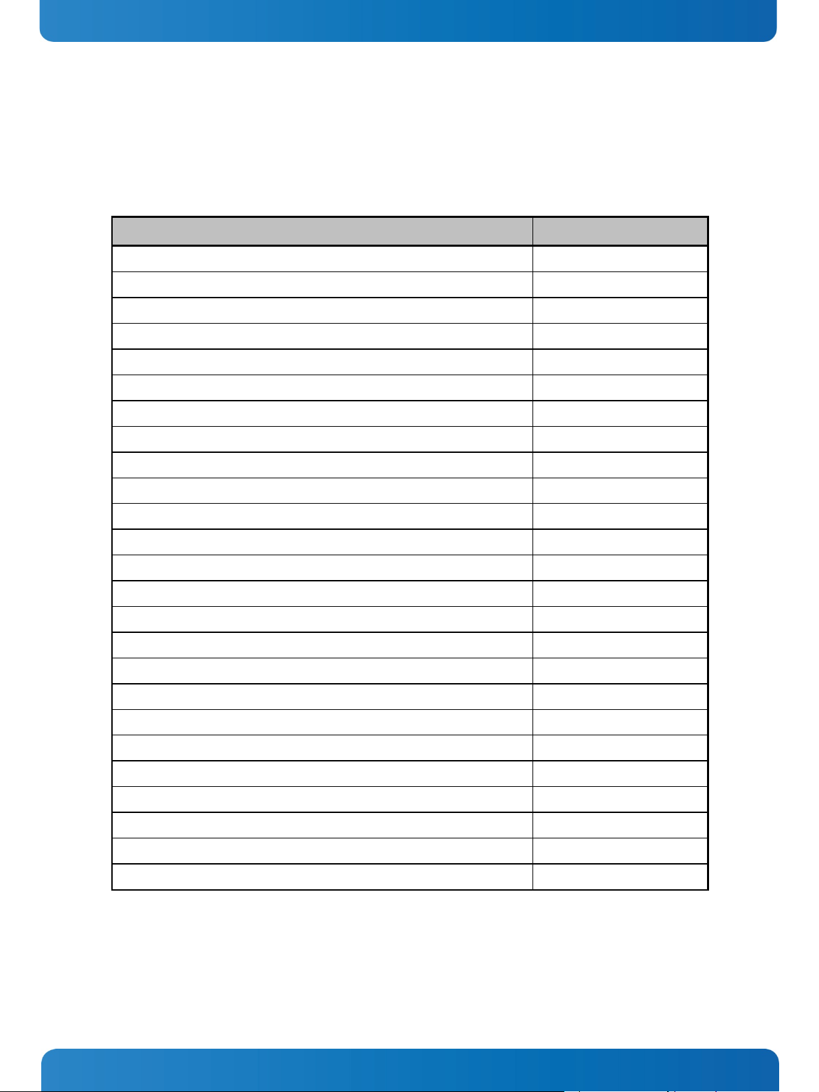
9.3. Connectors
Connectors connect this board with other parts of the system. Loose or improper connection might cause problems. Make
sure all connectors are properly and firmly connected.
Here is a summary table that shows you all connectors on the board.
Connector Label
www.kontron.com 17
Page 20
SATA Port 3
SATA4
SATA Port 4 (on edge connector)
(no label)
SATA Port 5 (on edge connector)
(no label)
COM1 Connector
COM1
COM2 Connector
COM2
Audio Connector
AUDIO1
ATX Connecter
ATX2
9. Jumpers and Connectors PCI 762 – User’s Guide (Version 1.0)
Connector Label
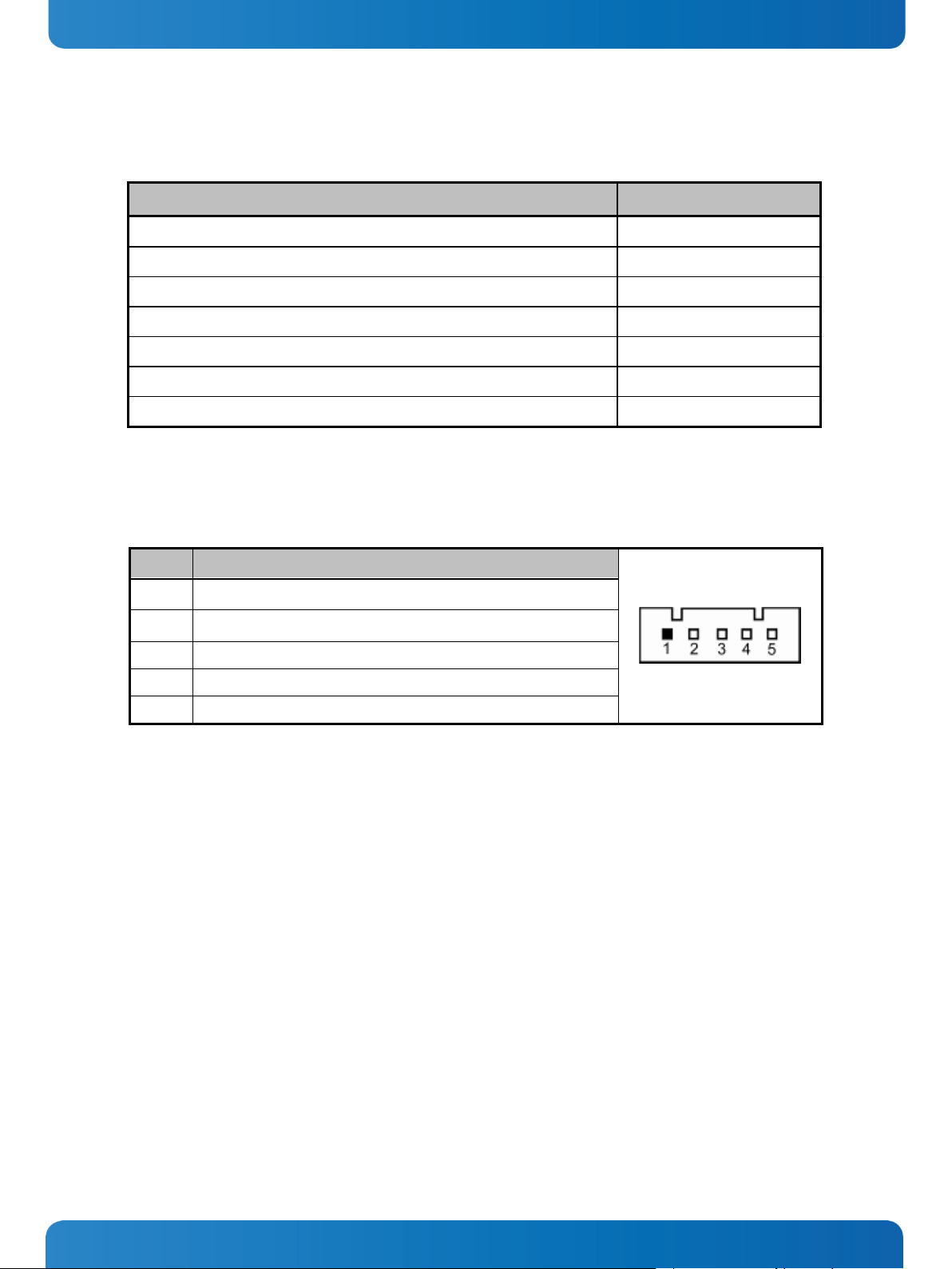
9.3.1. SMBUS Connector (CN1)
Connector SMBUS CN1 is for SMBUS interface support.
Pin Signal
1 CLOCK
2 N.C
3 GND
4 DATA
5 +5V
18 www.kontron.com
Page 21
9. Jumpers and Connectors PCI 762 – User’s Guide (Version 1.0)
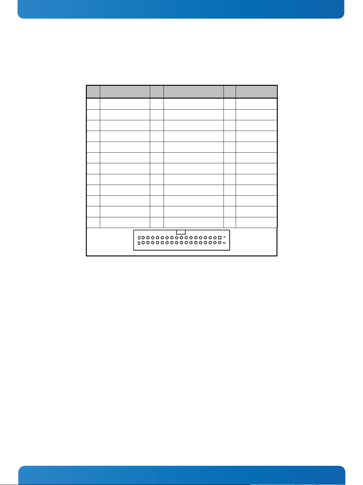
9.3.2. Floppy Disk Port Connector (CN4)
The board provides a 34-pin header type connector, CN4, supporting up to two floppy drives. The floppy drives may be any
one of the following types: 5.25" 360KB/1.2MB and 3.5" 720KB/1.44MB/2.88MB.
Pin Signal Pin Signal Pin Signal
1 GND 2 Drive Density Select 3 GND
4 No connector 5 GND 6 No connector
7 GND 8 Index# 9 GND
10 Motor enable A# 11 GND 12 No connector
13 GND 14 Drive select A# 15 GND
16 No connector 17 GND 18 Direction#
19 GND 20 STEP# 21 GND
22 Write data# 23 GND 24 Write gate#
25 GND 26 Track 0 # 27 GND
28 Write protect# 29 No connector 30 Read data#
31 GND 32 Head selection# 33 No connector
34 Disk change#
www.kontron.com 19
Page 22
Pin
Signal
Pin Signal
1
USB_PWR
2
USB_PWR
USB6-
4
USB7-
3
USB6+
6
USB7+
4
GND 8 GND 5 GND
10
GND
9. Jumpers and Connectors PCI 762 – User’s Guide (Version 1.0)
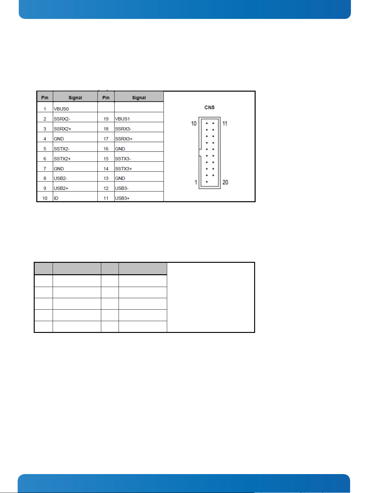
9.3.3. Internal USB Connectors (CN5)
The 19-pin standard Universal Serial Bus (USB 3.0) connectors, CN5 on this board is for installing versatile USB 3.0
interface peripherals.
9.3.4. Internal USB Connectors (CN8, CN10, CN13)
The 10-pin standard Universal Serial Bus (USB 2.0) connectors, CN8/10/13 on this board are for installing versatile USB
interface peripherals.
2
CN 13
The 5-pin standard Universal Serial Bus (USB) connectors, CN15, on this board are for installing versatile USB interface
peripherals.
20 www.kontron.com
Page 23
2
LINK_ACT LED(-)
3
100, Low Active
4
+3.3V
5
1000, Low Active
Pin
Signal
1
+ 3.3V
2
LINK_ACT LED(-)
3
100, Low Active
4
+3.3V
5
1000, Low Active
1
Red 2 Green
3
Blue 4 N.C 5 GND 6 DETECT
7
GND 8 GND 9 VCC
10
GND
11
N.C
12
DDC DATA
13
Horizontal Sync
14
Vertical Sync
15
DDC CLK
15
6
11
10
15
9. Jumpers and Connectors PCI 762 – User’s Guide (Version 1.0)
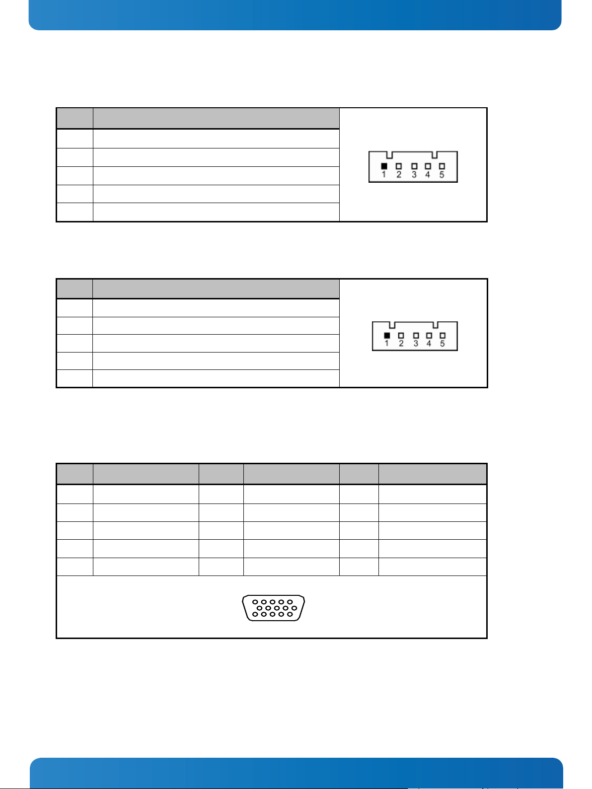
9.3.5. LAN2 LED Connectors (CN6)
Pin Signal
1 + 3.3V
9.3.6. LAN1 LED Connectors (CN7)
9.3.7. DB15 CRT Connector (CN11) Co-layout with CN12
CN11 is a DB15 connector commonly used for the CRT Monitor.
Pin Signal Pin Signal Pin Signal
www.kontron.com 21
Page 24
Pin
Signal
Pin
Signal
Pin
Signal
1
Data2-
2
Data2+
3
GND
4
N.C. 5 N.C.
6
DDC CLK
7
DDC Data
8
N.C.
9
Data1-
10
Data1+
11
GND
12
N.C.
13
N.C.
14
+5V
15
GND
16
HPD
17
Data0-
18
Data0+
19
GND
20
N.C.
21
N.C.
22
GND
23
Clock+
24
Clock-
9. Jumpers and Connectors PCI 762 – User’s Guide (Version 1.0)
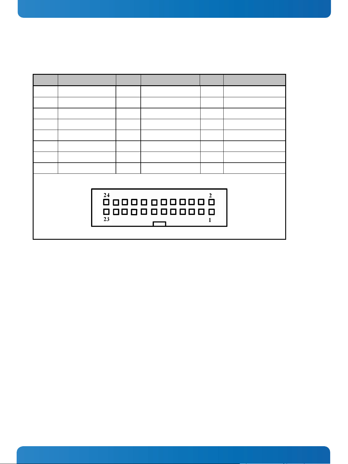
9.3.8. DVI-D Pin Header (CN14)
This board supports a 24-pin header (CN14) for DVI-D, via DVI-D cable.
22 www.kontron.com
Page 25
9. Jumpers and Connectors PCI 762 – User’s Guide (Version 1.0)
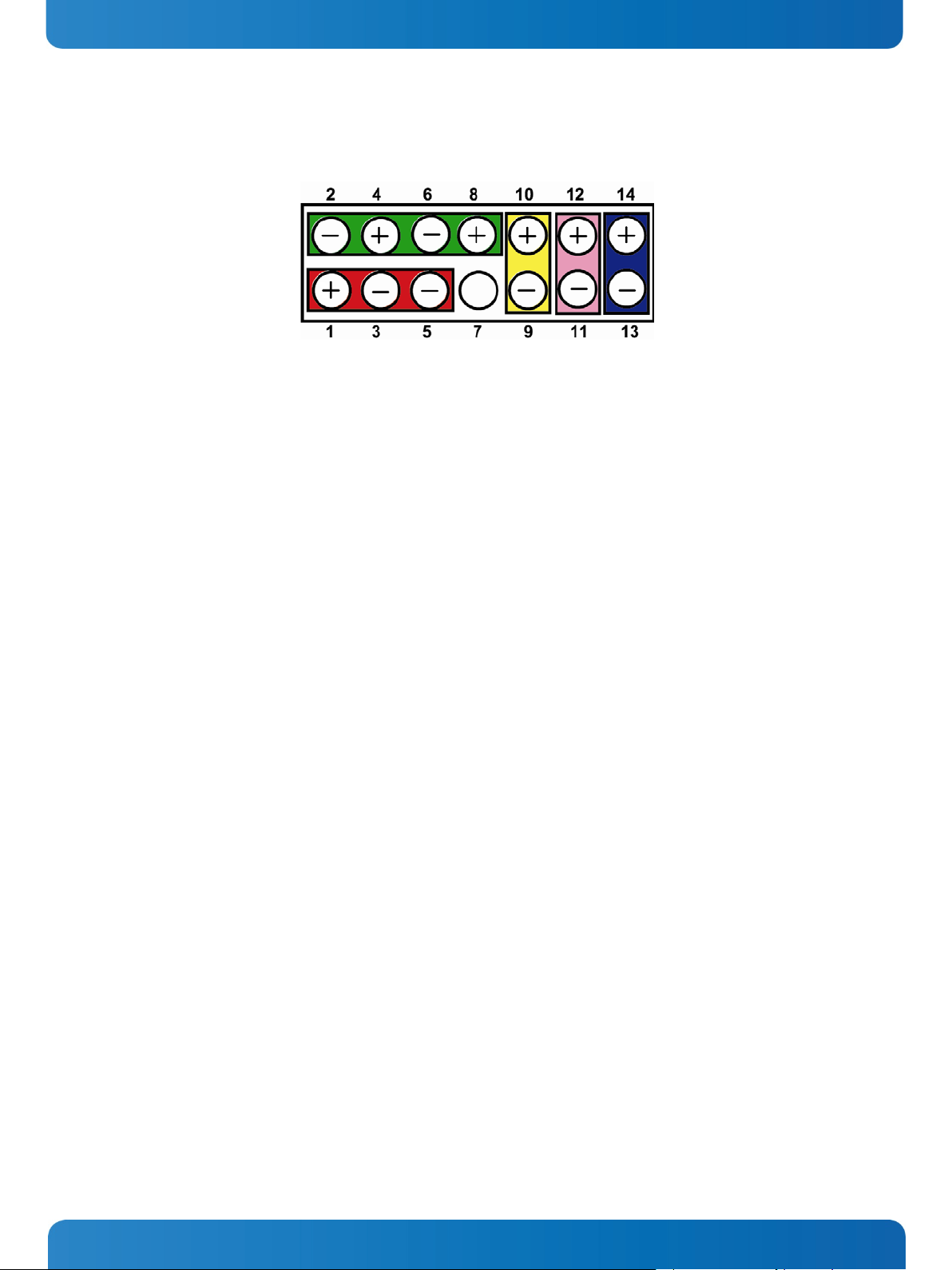
9.3.9. Front Panel Connector (CN15)
Power LED
This 3-pin connector denoted as Pin 1 and Pin 5 connects the system power LED indicator to such a switch on the case.
Pin 1 is assigned as +, and Pin 5 as -. The Power LED lights up when the system is powered ON. Pin 3 is defined as GND.
External Speaker and Internal Buzzer Connector
Pin 2, 4, 6 and 8 can be connected to the case-mounted speaker unit or internal buzzer. While connecting the CPU card
to an internal buzzer, please short pins 2-4; while connecting to an external speaker, you need to set pins 2-4 to Open
and connect the speaker cable to pin 8 (+) and pin 2 (-).
ATX Power On/Off Button
This 2-pin connector denoted as Pin 9 and 10 connects the front panel’s ATX power button to the CPU card, which
allows users to control ATX power supply to be power on/off.
System Reset Switch
Pin 11 and 12 can be connected to the case-mounted reset switch that reboots your computer instead of turning OFF
the power switch. It is a better way to reboot your system for a longer life of the system’s power supply.
HDD Activity LED
This connection is linked to hard drive activity LED on the control panel. LED flashes when HDD is being accessed. Pin
13 and 14 connect the hard disk drive to the front panel HDD LED, Pin 13 assigned as -, and Pin 14 as +.
www.kontron.com 23
Page 26
Pin
Signal
1
Clock
2
DATA
3
No connector
4
GND 5 5VSBY
9. Jumpers and Connectors PCI 762 – User’s Guide (Version 1.0)
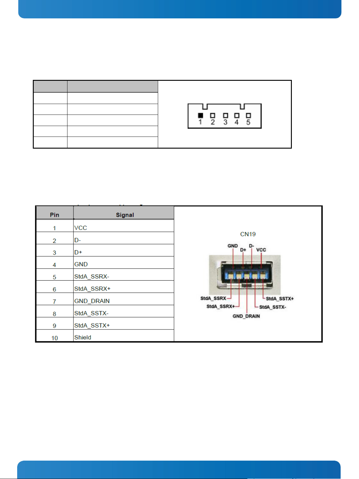
9.3.10. PS/2 Keyboard, Mouse Connectors (CN17, CN18)
The board provides the Keyboard (CN17) / Mouse (CN18) interface with a 5-pin connecter.
9.3.11. External USB 3.0 Port Connectors (CN16, CN19)
The 9-pin standard Universal Serial Bus (USB 3.0) port connector on the board is for the installation of peripherals
supporting the USB interface.
24 www.kontron.com
Page 27

Signal Name
RS-232
RS-422
RS-485
6
Clear to Send (CTS)
No connector
No connector
7
Data Terminal Ready (DTR)
RX-
No connector
8
Ring Indicator (RI)
No connector
No connector
9
Ground (GND)
GND
GND
10
Disconnect(NI)
NI
NI
9. Jumpers and Connectors PCI 762 – User’s Guide (Version 1.0)
9.3.12. RS232/422/485 Pin Assignment (COM1)
The serial interface for the board consists of COM1 support for RS-232 and COM1 for RS-232/RS-422/RS-485.
Pin
1 Data Carrier Detect (DCD) TX- DATA-
2 Data Set Ready (DSR) No connector No connector
3 Receive Data (RXD) TX+ DATA+
4 Request to Send (RTS) No connector No connector
5 Transmit Data (TXD) RX+ No connector
www.kontron.com 25
Page 28

Pin
Signal
Pin
Signal
Pin
Signal
Pin
Signal
9. Jumpers and Connectors PCI 762 – User’s Guide (Version 1.0)
9.3.13. COM Port RS-232 Pin Assignment (COM2)
COM2 Serial Port 10-pin (Box-header) Connector Pin Assignment list
1 Data Carrier Detect (DCD) 2 Data Set Ready (DSR)
3 Receive Data (RXD) 4 Request to Send (RTS)
5 Transmit Data (TXD) 6 Clear to Send (CTS)
7 Data Terminal Ready (DTR) 8 Ring Indicator (RI)
9 Ground (GND) 10 Disconnect(NI)
9.3.14. Intel
®
HD Audio Digital Header (AUDIO1)
1 MIC IN 2 GND
3 LINE_IN_L 4 GND
5 LINE_IN_R 6 GND
7 LINE_OUT_L 8 GND
9 LINE_OUT_R 10 GND
26 www.kontron.com
Page 29

1
GND 2 GND 3 GND 4 GND
5
+12V
6
+12V
7
+12V
8
+12V
1
2
3
4
9. Jumpers and Connectors PCI 762 – User’s Guide (Version 1.0)
9.3.15. ATX 8 Pin 12V IN Connector (ATX2)
You can connect it to the ATX12V power supply for CPU Core Voltage.
Pin Signal
9.3.16. A CPU fan is always needed for cooling CPU heat (FAN3)
The CPU fan connector FAN3 provides power to the CPU fan.
Pin Signal
Ground
+12V
Rotation Detection
Speed Control
9.3.17. System & Auxiliary Fan Connectors (FAN1, FAN2)
You can connect the system cooling fan cable to FAN1/FAN2 for system cooling fan power.
Pin Signal
1 GND
2 +12V
3 Rotation Detection
www.kontron.com 27
Page 30

12345678
A B
9. Jumpers and Connectors PCI 762 – User’s Guide (Version 1.0)
9.3.18. Ethernet RJ-45 Connectors (LAN1, LAN2)
The RJ-45 connectors LAN1 and LAN2 are for Ethernet. To connect the board to 100-Base-T or 1000-Base-T hub, just plug
one end of the cable into LAN1 and connect the other end (phone jack) to a 100-Base-T hub or 1000-Base-T hub.
Pin Signal
1 Tx+ (Data transmission positive)
2
Tx- (Data transmission negative)
3
Rx+(Data reception positive)
4 RJ-1(For 1000 base T-Only)
5 RJ-1(For 1000 base T-Only)
6
Rx- (Data reception negative)
7
RJ-1(For 1000 base T-Only)
8
RJ-1(For 1000 base T-Only)
A
Active LED
B Speed LED
28 www.kontron.com
Page 31

1
Strobe#
2
Auto Form Feed#
3
Data 0
4
Error#
5
Data 1
6
Initialize#
7
Data 2
8
Printer Select In#
9
Data 3
10
GND
11
Data 4
12
GND
13
Data 5
14
GND
15
Data 6
16
GND
17
Data 7
18
GND
19
Acknowledge#
20
GND
21
Busy
22
GND
23
Paper Empty#
24
GND
25
Printer Select
26
N.C
9. Jumpers and Connectors PCI 762 – User’s Guide (Version 1.0)
9.3.19. Parallel Port Connector (PRINT1) Print Port Connector
This board has a multi-mode parallel port to support:
Standard Mode:
IBM PC/XT, PC/AT and PS/2 are compatible with bi-directional parallel port.
Enhanced Mode:
Enhance parallel port (EPP) is compatible with EPP 1.7 and EPP 1.9 (IEEE 1284 compliant).
High Speed Mode:
Microsoft and Hewlett Packard extended capabilities port (ECP) is IEEE 1284 compliant.
Pin Signal Pin Signal
www.kontron.com 29
Page 32

1
2
3
4
5
6
7
9. Jumpers and Connectors PCI 762 – User’s Guide (Version 1.0)
9.3.20. SATA Connectors (SATA1[3.0], SATA2[3.0], SATA3, SATA4)
These SATA connectors are for high-speed SATA interface ports and they can be connected to hard disk devices.
Pin Signal
GND
SATA_TX+
SATA_TX-
GND
SATA_RX-
SATA_RX+
GND
30 www.kontron.com
Page 33

10. Lithium Battery PCI 762 – User’s Guide (Version 1.0)
10. Lithium Battery
PCI-762 is provided with a 3.0 V “coin cell” lithium battery for the RTC operation and CMOS Setup RAM. Please observe the
chapter 3.1 “Safety Instructions for the Lithium Battery”.
10.1. Replacing the Lithium Battery
To replace the battery please proceed as follows:
1. Turn the power off.
2. If your system is equipped with expansion cards, remove them first, if necessary.
3. Remove the battery by pressing outwards the ejector spring.
4. Insert the new battery into the socket.
5. Make sure that you insert the battery correctly. The minus pole must be positioned as marked in the picture included in
the section 9.1 “Board Layout”.
The lithium battery must be replaced with an identical battery or a battery type recommended by Kontron Embedded
Computers (Lithium battery 3.0 V for RTC, type: CR2032).
Caution!
Danger of explosion when replaced with wrong type of battery. Replace the battery only with
UL recognized Lithium battery that has the same or equivalent type recommended by Kontron.
Do not dispose of lithium batteries in domestic waste. Dispose of the battery according to the local
regulations dealing with the disposal of these special materials (e.g. to the collecting points for the
disposal of batteries).
www.kontron.com 31
Page 34

11. Hardware Description PCI 762 – User’s Guide (Version 1.0)
11. Hardware Description
11.1. Processors
The PCI-762 Series supports Intel® Core™ 2 Quad / Core™ 2 Duo/Celeron® processors, which make your system operated
under Windows® XP and Linux environments. The system performance depends on the processor. Make sure all correct
settings are arranged for your installed processor to prevent the CPU from damages.
11.2. BIOS
The PCI-762 Series uses AMI Plug and Play BIOS with a single 32Mbit SPI Flash.
11.3. System Memory
The PCI-762 supports four 240-pin DDR3 DIMM sockets for a maximum memory of 8GB DDR3 SDRAMs. The memory module
can come in sizes of 1GB, 2GB and 4GB.
32 www.kontron.com
Page 35

Apply pressure to corner with right-hand thumb when opening or closing load lever - otherwise lever will
11. Hardware Description PCI 762 – User’s Guide (Version 1.0)
11.4. Hardware Installation
Before installing the processor, please access Intel® website for more detailed information
Processor Integration Video (LGA1155):
http://www.intel.com/support/tw/processors/sb/CS-030860.htm
11.4.1. Installing the Processor
The LGA1155 processor socket comes with a cover to protect the processor. Please install the processor into the CPU socket
step by step as below:
Step1: Opening the Socket
1. Disengage load lever by releasing down and out on the hook. This will clear retention tab.
2. Rotate load lever to open position at approximately 135°.
3. Rotate load plate to open position at approximately 150°.
.
www.kontron.com 33
bounce back (as a mouse trap) causing bent contacts.
Page 36

11. Hardware Description PCI 762 – User’s Guide (Version 1.0)
Step 2: Removing the socket protective cover
1. Place thumb against the front edge of the protective cover and rest index finger on the rear grip to maintain control of
the cover.
2. Lift the front edge of the protective cover to disengage from the socket. Keep control of the cover by holding the rear
grip with index finger.
3. Lift protective cover away from the socket, being careful not to touch the electrical contacts.
Vertical removal is NOT recommended, as it requires higher force and can lead to socket contact damage.
Never Touch Fragile Socket Contacts to Avoid Damage and DO NOT TOUCH PROCESSOR SENSITIVE CONTACTS
AT ANY TIME DURING INSTALLATION.
34 www.kontron.com
Page 37

11. Hardware Description PCI 762 – User’s Guide (Version 1.0)
Step 3: Processor installation
1. Lift processor package from shipping media by grasping the substrate edges. Scan the processor package gold pads for
any presence of foreign material. If necessary, the gold pads can be wiped clean with a soft lint-free cloth and isopropyl
alcohol.
2. Scan the processor package gold pads for any presence of foreign material. If necessary, the gold pads can be wiped
clean with a soft lint-free cloth and isopropyl alcohol.
3. Locate connection 1 indicator on the processor which aligns with connection 1 indicator chamfer on the socket, and
notice processor keying features that line up with posts along socket walls.
4. Grasp the processor with thumb and index finger along the top and bottom edges. (Do not touch the Orientation
Notches.) The socket will have cutouts for your fingers to fit into (see image below).
5. Carefully place the processor into the socket body vertically (see image below).
www.kontron.com 35
Tilting or roughly shifting it into place can damage socket contacts.
Do not use a vacuum pen for installation.
Page 38

11. Hardware Description PCI 762 – User’s Guide (Version 1.0)
6. Verify that package is within the socket body and properly connected to orientation keys.
36 www.kontron.com
Page 39

11. Hardware Description PCI 762 – User’s Guide (Version 1.0)
7. Close the socket (see image below):
a. Gently lower the load plate.
b. Make sure load plate's front edge slides under the shoulder screw cap as the lever is lowered.
c. Latch the lever under the top plate's corner tab, being cautious not to damage the motherboard with the tip of the
lever.
Step 4: Fan heatsink handling
1. Orientate the CPU cooling fan to fixing holes on the board.
2. Screw the CPU cooling fan onto the board.
3. Make sure the CPU fan is plugged to the CPU fan connector.
www.kontron.com 37
Page 40

11. Hardware Description PCI 762 – User’s Guide (Version 1.0)
11.5. Installing the Memory
The board supports two 240-pin DDR3 DIMM memory sockets with maximum memory capacity up to 16GB.
Please follow the steps below to install the memory modules:
1. Push down latches on each side of the DIMM socket.
2. Align the memory module with the socket that notches of memory module must match the socket keys for a correct
installation.
3. Install the memory module into the socket and push it firmly down until it is fully seated. The socket latches are levered
upwards and clipped on to the edges of the DIMM.
4. Install any remaining DIMM modules.
38 www.kontron.com
Page 41

12. AMI BIOS Utility PCI 762 – User’s Guide (Version 1.0)
12. AMI BIOS Utility
This chapter provides users with detailed description how to set up basic system configuration through the AMIBIOS8 BIOS
setup utility.
12.1. Starting
To enter the setup screens, follow the steps below:
1. Turn on the computer and press the <Del> key immediately.
2. After you press the <Delete> key, the main BIOS setup menu displays. You can access the other setup screens from the
main BIOS setup menu, such as the Chipset and Power menus.
12.2. Navigation Keys
The BIOS setup/utility uses a key-based navigation system called hot keys. Most of the BIOS setup utility hot keys can be
used at any time during the setup navigation process.
These keys include <F1>, <F10>, <Enter>, <ESC>, <Arrow> keys, and so on.
Some of navigation keys differ from one screen to another.
Left/Right
Up/Down
+− Plus/Minus
Tab The <Tab> key allows you to select setup fields.
F1 The <F1> key allows you to display the General Help screen.
F2 The <F2> key allows you to Load Previous Values.
F3 The <F3> key allows you to Load Optimized Defaults.
F4
The Left <Arrow> keys allow you to select a setup screen.
The Up and Down <Arrow> keys allow you to select a setup screen or subscreen.
The Plus and Minus <Arrow> keys allow you to change the field value of a
particular setup item.
The <F4> key allows you to save any changes you have made and exit Setup.
Press the <F4> key to save your changes.
The <Esc> key allows you to discard any changes you have made and exit
Esc
Enter
www.kontron.com 39
the Setup. Press the
<Esc> key to exit the setup without saving your changes.
The <Enter> key allows you to display or change the setup option listed for
a particular setup item. The <Enter> key can also allow you to display the
setup sub- screens.
Page 42

This information depends
on board version
12. AMI BIOS Utility PCI 762 – User’s Guide (Version 1.0)
12.3. Main Menu
When you first enter the Setup Utility, you will enter the Main setup screen. You can always return to the Main setup screen
by selecting the Main tab. There are two Main Setup options. They are described in this section. The Main BIOS Setup screen
is shown below.
System Date/Time
Use this options to change the system date and time. Highlight System Date or System Time using the
<Arrow> keys. Enter new values through the keyboard. Press the <Tab> key or the <Enter> keys to move
between fields. The date must be entered in MM/DD/YY format. The time is entered in HH:MM:SS format.
40 www.kontron.com
Page 43

12. AMI BIOS Utility PCI 762 – User’s Guide (Version 1.0)
12.4. Advanced Menu
The Advanced menu also allows users to set configuration of the CPU and other system devices. You can select any of the
items in the left frame of the screen to go to the sub menus (refer to picture below).
For items marked with “”, please press <Enter> for more options.
Important
Setting incorrect field values may cause the system to malfunction.
www.kontron.com 41
Page 44

12. AMI BIOS Utility PCI 762 – User’s Guide (Version 1.0)
12.4.1. ACPI Settings
You can use this screen to select options for the ACPI Configuration, and change the value of the selected option. A
description of the selected item appears on the right side of the screen.
ACPI Sleep State
Allows you to select the Advanced Configuration and Power Interface (ACPI) state to be used for system
suspend. Here are the options for your selection, S1 (CPU Stop Clock), S3 (Suspend to RAM) and Suspend
Disable.
42 www.kontron.com
Page 45

12. AMI BIOS Utility PCI 762 – User’s Guide (Version 1.0)
12.4.2. Trusted Computing
You can use this screen to select options for the Trusted Computing, and change the value of the selected option. A
description of the selected item appears on the right side of the screen.
www.kontron.com 43
Page 46

12. AMI BIOS Utility PCI 762 – User’s Guide (Version 1.0)
12.4.3. CPU Configuration
This screen shows the CPU Configuration, and you can change the value of the selected option.
Hyper-threading
This item can set enable or disable for support Hyper-threading Technology.
Intel Virtualization Technology
Allows a hardware platform to run multiple operating systems separately and simultaneously, enabling one
system to virtually function as several systems.
44 www.kontron.com
Page 47

12. AMI BIOS Utility PCI 762 – User’s Guide (Version 1.0)
12.4.4. SATA Configuration
You can use this screen to select options for the SATA Configuration, and change the value of the selected option. A
description of the selected item appears on the right side of the screen.
SATA Mode
Use this item to choose the SATA operation mode. Here are the options for your selection, IDE Mode, AHCI
Mode and RAID Mode.
www.kontron.com 45
Page 48

12. AMI BIOS Utility PCI 762 – User’s Guide (Version 1.0)
12.4.5. PCH-FW Configuration
This screen displays information about the ME firmware.
46 www.kontron.com
Page 49

12. AMI BIOS Utility PCI 762 – User’s Guide (Version 1.0)
12.4.6. AMT Configuration
You can use this screen to select options for the Intel AMT Configuration, and change the value of the selected option. A
description of the selected item appears on the right side of the screen.
INTEL AMT
Disable ME
You can enable this item to support AMT (active management technology) function to follow up the procedure
for the access to AMI program screen.
Use this item to unconfigure the ME settings.
www.kontron.com 47
Page 50

12. AMI BIOS Utility PCI 762 – User’s Guide (Version 1.0)
12.4.7. USB Configuration
You can use this screen to select options for the USB Configuration, and change the value of the selected option. A
description of the selected item appears on the right side of the screen.
48 www.kontron.com
Page 51

12. AMI BIOS Utility PCI 762 – User’s Guide (Version 1.0)
12.4.8. Super IO Configuration
You can use this screen to select options for the Super IO Configuration, and change the value of the selected option. A
description of the selected item appears on the right side of the screen. For items marked with “”, please press <Enter>
for more options.
Floppy Disk Controller Configuration
You can use this screen to select options for the Floppy Configuration, and change the value of the selected
option.
Serial Port 1 Configuration
This option specifies the base I/O port address and Interrupt Request address of serial port 1. The Optimal
setting is 2F8/IRQ3.
Serial Port 2 Configuration
This option specifies the base I/O port address and Interrupt Request address of serial port 1. The Optimal
setting is 3F8/IRQ4.
Parallel Port C on figuration
This item allows you to determine the Parallel Port Mode and I/O address for onboard parallel port.
www.kontron.com 49
Page 52

12. AMI BIOS Utility PCI 762 – User’s Guide (Version 1.0)
12.4.9. H/W Monitor
This screen shows the Hardware Health Configuration, and a description of the selected item appears on the right side of
the screen.
Smart Fan Function
This item can enable or disable the Smart Fan function.
Smart Fan Mode Configuration
This item can adjust the CPU/System/Auxiliary Fan speed automatically in accordance with the current
CPU/System temperature that can prevent the system overheating.
The Auxiliary Fan also in accordance with current CPU temperature.
There are these options Manual Mode and Thermal Cruise Mode.
50 www.kontron.com
Page 53

12. AMI BIOS Utility PCI 762 – User’s Guide (Version 1.0)
12.4.10. Intel RC Drivers Version Detail
This screen shows the version numbers of the Intel RC drivers.
www.kontron.com 51
Page 54

12. AMI BIOS Utility PCI 762 – User’s Guide (Version 1.0)
12.5. Chipset Menu
The Chipset menu allows users to change the advanced chipset settings. You can select any of the items in the left frame of
the screen to go to the sub menus:
PCH-IO Configuration
System Agent (SA) Configuration
For items marked with “”, please press <Enter> for more options.
52 www.kontron.com
Page 55

12. AMI BIOS Utility PCI 762 – User’s Guide (Version 1.0)
12.5.1. PCH-IO Configuration
This screen shows the PCH Azalia Audio Interface Configuration, and a description of the selected item appears on the right
side of the screen.
www.kontron.com 53
Page 56

12. AMI BIOS Utility PCI 762 – User’s Guide (Version 1.0)
12.5.2. System Agent (SA) Configuration
It is strongly recommended that you do not modify these options unless you are an advanced user.
54 www.kontron.com
Page 57

12. AMI BIOS Utility PCI 762 – User’s Guide (Version 1.0)
Boot Menu
The Boot menu allows users to change boot options of the system. You can select any of the items in the left frame of the
screen to go to the sub menus:
Setup Prompt Timeout
Bootup NumLock State
Quiet Boot
CSM16 Module Verison
GateA20 Active
Boot Option Priorities
Quiet Boot
Use this item to enable or disable the Quite Boot state. The default setting is disabling.
Bootup NumLock State
Use this item to select the power-on state for the NumLock. The default setting is on.
www.kontron.com 55
Page 58

12. AMI BIOS Utility PCI 762 – User’s Guide (Version 1.0)
12.6. Security Menu
The Security menu allows users to change the security settings for the system.
Administrator Password
This item indicates whether an administrator password has been set. If the password has been installed,
Installed displays. If not, Not Installed displays.
User Password
This item indicates whether a user password has been set. If the password has been installed, Installed
displays. If not, Not Installed displays.
56 www.kontron.com
Page 59

12. AMI BIOS Utility PCI 762 – User’s Guide (Version 1.0)
12.7. Save & Exit Menu
The Save & Exit menu allows users to load your system configuration with optimal or failsafe default values .
Save Changes and Exit
When you have completed the system configuration changes, select this option to leave Setup and return to
Main Menu. Select Save Changes and Exit from the Save & Exit menu and press <Enter>. Select Yes to save
changes and exit.
Discard Changes and Exit
Select this option to quit Setup without making any permanent changes to the system configuration and
return to Main Menu. Select Discard Changes and Exit from the Save & Exit menu and press <Enter>. Select
Yes to discard changes and exit.
Save Changes and Reset
When you have completed the system configuration changes, select this option to leave Setup and reboot the
computer so the new system configuration parameters can take effect. Select Save Changes and Reset from
the Save & Exit menu and press <Enter>. Select Yes to save changes and reset.
Discard Changes and Reset
Select this option to quit Setup without making any permanent changes to the system configuration and
reboot the computer. Select Discard Changes and Reset from the Save & Exit menu and press <Enter>. Select
Yes to discard changes and reset.
Save Changes
When you have completed the system configuration changes, select this option to save changes. Select Save
Changes from the Save & Exit menu and press <Enter>. Select Yes to save changes.
Discard Changes
Select this option to quit Setup without making any permanent changes to the system configuration. Select
Discard Changes from the Save & Exit menu and press <Enter>. Select Yes to discard changes.
www.kontron.com 57
Page 60

12. AMI BIOS Utility PCI 762 – User’s Guide (Version 1.0)
Restore Defaults
It automatically sets all Setup options to a complete set of default settings when you select this option. The
Optimal settings are designed for maximum system performance, but may not work best for all computer
applications. In particular, do not use the Optimal Setup options if your computer is experiencing system
configuration problems. Select Restore Defaults from the save & Exit menu and press <Enter>.
58 www.kontron.com
Page 61

↓
↓
↓
↓
↓
13. Watchdog Timer PCI 762 – User’s Guide (Version 1.0)
13. Watchdog Timer
13.1. Watchdog Timer Setting
After the system stops working for a while, it can be auto-reset by the Watchdog Timer. The integrated Watchdog Timer can
be set up in the system reset mode by program.
Using the Watchdog Function
Start
Un-Lock WDT
:O 2E 87 ;
O 2E 87 ;
Un-lock super I/O
Un-lock super I/O
Set WDT Function
O 2E 2D
O 2F 20
Select Logic device
O 2E 07
O 2F 08
Activate WDT
:O 2E 30
O 2F 01
Set Second or Minute
O 2E F5
O 2F N
Set base timer
:O 2E F6
N=00 or 08(See below table)
O 2F M=00, 01, 02 FF(Hex) ,Value=0 to 255
www.kontron.com 59
Page 62

↓
13. Watchdog Timer PCI 762 – User’s Guide (Version 1.0)
WDT counting
re-set timer :O 2E F6
O 2F M ; M=00,01,02,…FF(See below table)
IF No re-set timer : WDT time-out, generate RESET
IF to disable WDT : O 2E 30
O 2F 00; Can be disable at any time
N=00
M= 00h: Time-out Disable
01h: Time-out occurs after 1 second
02h: Time-out occurs after 2 second
03h: Time-out occurs after 3 second
……………………….......................................
FFh: Time-out occurs after 255 second
N=08
M= 00h: Time-out Disable
01h: Time-out occurs after 1 minute
02h: Time-out occurs after 2 minutes
03h: Time-out occurs after 3 minutes
FFh: Time-out occurs after 255 minutes
60 www.kontron.com
Page 63

14. PCI IRQ Routing PCI 762 – User’s Guide (Version 1.0)
14. PCI IRQ Routing
14.1. PICMG PCI IRQ Routing
Device ID Slot Int
PCI Slot 0 31 0 BCDA
PCI Slot 1 30 1 CDAB
PCI Slot 2 29 2 DABC
PCI Slot 3 28 3 ABCD
www.kontron.com 61
Page 64

15. Configuring SATA for RAID PCI 762 – User’s Guide (Version 1.0)
15. Configuring SATA for RAID
15.1. Configuring SATA Hard Drive(s) for RAID Function (Controller: Intel
Please follow up the steps below to configure SATA hard drive(s):
(1) Install SATA hard drive(s) in your system.
(2) Enter the BIOS Setup to configure SATA controller mode and boot sequence.
(3) Configure RAID by the RAID BIOS.
(4) Create a floppy disk for the SATA controller driver.
(5) Install the SATA controller driver during the OS installation.
Before you begin the SATA configuration, please prepare:
(a) Two SATA hard drives (to ensure optimal performance, it is recommended that you use two hard drives with identical
model and capacity). If you do not want to create RAID with the SATA controller, you may prepare only one hard drive.
(b) An empty formatted floppy disk
(c) Windows XP setup disk
(1) Installing SATA hard drive(s) in your system
®
Q77)
Connect one end of the SATA signal cable to the rear of the SATA hard drive, and the other end to available SATA port(s) on
the board. Then, connect the power connector of power supply to the hard drive.
(2) Configuring SATA controller mode and boot sequence by the BIOS Setup
You have to make sure whether the SATA controller is configured correctly by system BIOS Setup and set up BIOS boot
sequence for the SATA hard drive(s).
62 www.kontron.com
Page 65

15. Configuring SATA for RAID PCI 762 – User’s Guide (Version 1.0)
(2)-1-1 Turn on your system, and then press the Del button to enter BIOS Setup during running POST (Power-On
Self Test). If you want to create RAID, just go to the Advanced Settings menu/IDE configuration, select the
Configure SATA#1 as, and press <Enter> for more options.
(2)-1-2 A list of options appears, please select RAID.
www.kontron.com 63
Page 66

15. Configuring SATA for RAID PCI 762 – User’s Guide (Version 1.0)
(2)-2 Set CDROM for First Boot Device under the Boot Settings menu to boot CD-ROM after system restarts.
(2)-3 Save and exit the BIOS Setup.
64 www.kontron.com
Page 67

15. Configuring SATA for RAID PCI 762 – User’s Guide (Version 1.0)
(3) Configuring RAID by the RAID BIOS
Enter the RAID BIOS setup utility to configure a RAID array. Skip this step and proceed to Section 4 if you do not want to
create a RAID.
(3)-1 After the POST memory testing and before the operating system booting, a message "Press <Ctrl-I> to enter
Configuration Utility" shows up, accordingly, press <CTRL+ I> to enter the RAID BIOS setup utility.
(3)-2 After you press <CTRL+ I>, the Create RAID Volume screen will appear. If you want to create a RAID array,
select the Create RAID Volume option in the Main Menu and press ENTER.
www.kontron.com 65
Page 68

15. Configuring SATA for RAID PCI 762 – User’s Guide (Version 1.0)
(3)-3-1 After entering the CREATE VOLUME MENU screen, you can type the disk array name with 1~16 letters
(letters cannot be special characters) in the item “Name”.
(3)-3-2 When finished, press ENTER to select a RAID level. There are three RAID levels, RAID0, RAID1 and RAID5 &
RAID10. Select a RAID level and press ENTER.
66 www.kontron.com
Page 69

15. Configuring SATA for RAID PCI 762 – User’s Guide (Version 1.0)
(3)-4 Set the stripe block size. The KB is the standard unit of stripe block size. The stripe block size can be 4KB to
128KB. After the setting, press ENTER for the array capacity.
(3)-5 After setting all the items on the menu, select Create Volume and press ENTER to start creating the RAID
array.
www.kontron.com 67
Page 70

15. Configuring SATA for RAID PCI 762 – User’s Guide (Version 1.0)
(3)-6 When prompting the confirmation, press “Y“ to create this volume, or “N“ to cancel the creation.
After the creation is completed, you can see detailed information about the RAID Array in the DISK/VOLUME INFORMATION
section, including RAID mode, disk block size, disk name, and disk capacity, etc.
68 www.kontron.com
Page 71

15. Configuring SATA for RAID PCI 762 – User’s Guide (Version 1.0)
Delete RAID Volume
If you want to delete a RAID volume, select the Delete RAID Volume option in Main Menu. Press ENTER and follow onscreen instructions.
Please press [ESC] to exit the RAID BIOS utility.
Now, you can proceed to install a SATA driver controller and the operating system.
www.kontron.com 69
Page 72

15. Configuring SATA for RAID PCI 762 – User’s Guide (Version 1.0)
(4) Making a SATA Driver Disk
To install the operating system onto a serial ATA hard disk successfully, you need to install the SATA controller driver
during the OS installation. Without the driver, the hard disk may not be recognized during the Windows setup process. First
of all, please format a blank floppy disk. Secondly, follow up these steps below to produce a SATA driver disk.
Users can insert the Driver CD and the formatted blank floppy disk in another system. And then, please copy all of file of the
f6flpy32 folder in the Driver CD to a floppy disk.
Please copy all of file of the f6flpy64 folder, if installing 64-bit Windows Operating System.
70 www.kontron.com
Page 73

15. Configuring SATA for RAID PCI 762 – User’s Guide (Version 1.0)
(5) Installing the SATA controller driver during the OS installation
Now, the SATA driver disk is ready, and BIOS settings configured, you can proceed to install Windows 2000/XP onto your
SATA hard drive using the SATA driver. Here is an example for Windows XP installation.
(5)-1 Restart your system to boot the Windows 2000/XP Setup disk, and press F6 button as soon as you see the
message "Press F6 if you need to install a 3rd party SCSI or RAID driver". After pressing the F6 button, there
will be a few moments for some files being loaded before next screen appears.
(5)-2 When you see the screen below, insert the floppy disk containing the SATA driver and press “S”.
www.kontron.com 71
Page 74

15. Configuring SATA for RAID PCI 762 – User’s Guide (Version 1.0)
(5)-3 If the Setup correctly recognizes the driver of the floppy disk, a controller menu will appear below. Use the
ARROW keys to select Intel® ICH8R/ICH9R/ICH10R/DO/PCH SATA RAID Controller and press ENTER. Then
it will begin to load the SATA driver from the floppy disk.
If a message on the screen saying that one or some file(s) cannot be found, please check the floppy disk or
copy the correct SATA driver again from the driver CD.
If you are installing AHCI, Please select”Intel® 7 Series/C216 Chipset Family SATA AHCI Controller
72 www.kontron.com
Page 75

16. iAMT Settings PCI 762 – User’s Guide (Version 1.0)
16. iAMT Settings
The Intel® Active Management Technology (Intel® iAMT) has decreased a major barrier to IT efficiency that uses built-in
platform capabilities and popular third-party management and security applications to allow IT a better discovering,
healing, and protection their networked computing assets.
In order to utilize Intel iAMT you must enter the ME BIOS (CTRL + P during system startup), change the ME BIOS password,
and then select “Intel
®
iAMT” as the manageability feature.
16.1. Entering MEBx
1. You must go to BIOS TO start iAMT function.
2. Exit from BIOS after starting iAMT, and press Ctrl+P to enter MEBx Setting.
It is better to press Ctrl+P before the screen popping out.
www.kontron.com 73
Page 76

16. iAMT Settings PCI 762 – User’s Guide (Version 1.0)
16.2. Set & Change Password
1. You will be asked to set a password when first log in. The default password is ‘admin’.
2. You will be asked to change the password before setting ME.
74 www.kontron.com
Page 77

、
、
16. iAMT Settings PCI 762 – User’s Guide (Version 1.0)
3. You must confirm your new password while revising (as Remark 1):
The new password must contain:
(example: !!11qqQQ) (default value) Eight characters
• One upper case
• One lower case
• One number
• One special symbol, such as !
• (
" , excepted)
Underline ( _ ) and space are valid characters for password, but they won’t make higher complexity.
$ or ; ,
www.kontron.com 75
Page 78

16. iAMT Settings PCI 762 – User’s Guide (Version 1.0)
16.3. Intel
1. Select Intel
®
iAMT Settings
®
iAMT Configuration and press <ENTER>.
2. Select Network Setup to configure AMT.
76 www.kontron.com
Page 79

16. iAMT Settings PCI 762 – User’s Guide (Version 1.0)
3. Select TCP/IP to get into Network interface, and set it to ‘ENABLED’; into DHCP Mode, and set it to ‘DISABLED’ (as
Remark 2):
(3-1)
(3-2)
www.kontron.com 77
Page 80

16. iAMT Settings PCI 762 – User’s Guide (Version 1.0)
Remark 2 If DHCP Mode is disabled, you can make the following settings:
IP address
Subnet mask
78 www.kontron.com
Page 81

16. iAMT Settings PCI 762 – User’s Guide (Version 1.0)
4. Back to Intel (R) AMT Configuration, then select Activate Network Acess and press <ENTER>.
5. Exit from MEBx after completing the iAMT settings.
www.kontron.com 79
Page 82

16. iAMT Settings PCI 762 – User’s Guide (Version 1.0)
16.4. iAMT Web Console
1. From a web browser, please type http://(IP ADDRESS):16992, which connects to iAMT Web.
Example: http://10.1.40.214:16992
2. To log on, you will be required to type in username and password for access to the Web.
USER: admin (default value)
PASS: (MEBx password)
80 www.kontron.com
Page 83

16. iAMT Settings PCI 762 – User’s Guide (Version 1.0)
3. Enter the iAMT Web.
4. Click Remote Control, and select commands on the right side.
5. When you have finished using the iAMT Web console, close the Web browser.
www.kontron.com 81
Page 84

17. Technical Support PCI 762 – User’s Guide (Version 1.0)
17. Technical Support
For technical support, please contact our Technical Support department:
e-mail: support@kontron.com
Web: http://www.kontron.com/support
Make sure you have the following information on hand when you call:
• the unit part id number (PN),
• the serial number (SN) of the unit; the serial number can be found on the type label, placed on the rear side of the
system.
Be ready to explain the nature of your problem to the service technician.
If you have questions about Kontron Europe or our products and services, you can reach us by e-mail or at:
www.kontron.com .
17.1. Returning Defective Merchandise
Please follow these steps before you return any merchandise to Kontron Europe:
1. Download the corresponding form for returning a device with an RMA No. [RMA (Return of Material Authorization)]
from our website www.kontron.com / Support / RMA Information.
You also can contact our Customer Service department to obtain an RMA No.:
e-Mail: service@kontron.com
2. Ensure that you have received an RMA number from Kontron Customer Services before returning any device. Write this
number clearly on the outside of the package.
3. Describe the fault that has occurred.
4. Please provide the name and telephone number of a person we can contact to obtain more information, where
necessary. Where possible, please enclose all the necessary customs documents and invoices.
5. When returning a device:
• Pack it securely in its original box.
• Enclose a copy of the RMA form with the consignment.
Corporate Offices
Europe, Middle East & Africa
Oskar-von-Miller-Str. 1
85386 Eching/Munich
Germany
Tel.: +49 (0)8165/ 77 777
Fax: +49 (0)8165/ 77 219
info@kontron.com
North America
14118 Stowe Drive
Poway, CA 92064-7147
USA
Tel.: +1 888 294 4558
Fax: +1 858 677 0898
info@us.kontron.com
Asia Pacific
17 Building,Block #1,ABP.
188 Southern West 4th Ring
Beijing 100070, P.R.China
Tel.: + 86 10 63751188
Fax: + 86 10 83682438
info@kontron.cn
82 www.kontron.com
 Loading...