

Page 1

PB-SIO4A
Quad Serial Port Piggyback
RS422/RS485
Manual ID 19958, Rev. Index 0300
Sep 99
The product described in this manual is
in compliance with all applied CE standards.
Page 2

This page was intentionally left blank.
® PEP Modular Computers GmbH
Page 3

PB-SIO4A Preface
Preface
Revision History........................................................... 0 - 4
Trademarks.................................................................. 0 - 4
Explanation of Symbols ............................................... 0 - 5
For Your Safety............................................................ 0 - 6
High Voltage Safety Instructions.............................. 0 - 6
Special Handling and Unpacking Instructions.......... 0 - 6
General Instructions on Usage................................. 0 - 7
Two Years Warranty .................................................... 0 - 8
Table of Contents......................................................... 0 - 9
ID 19958, Rev. 0300 Page 0 - 3® PEP Modular Computers GmbH
Page 4
Preface PB-SIO4A
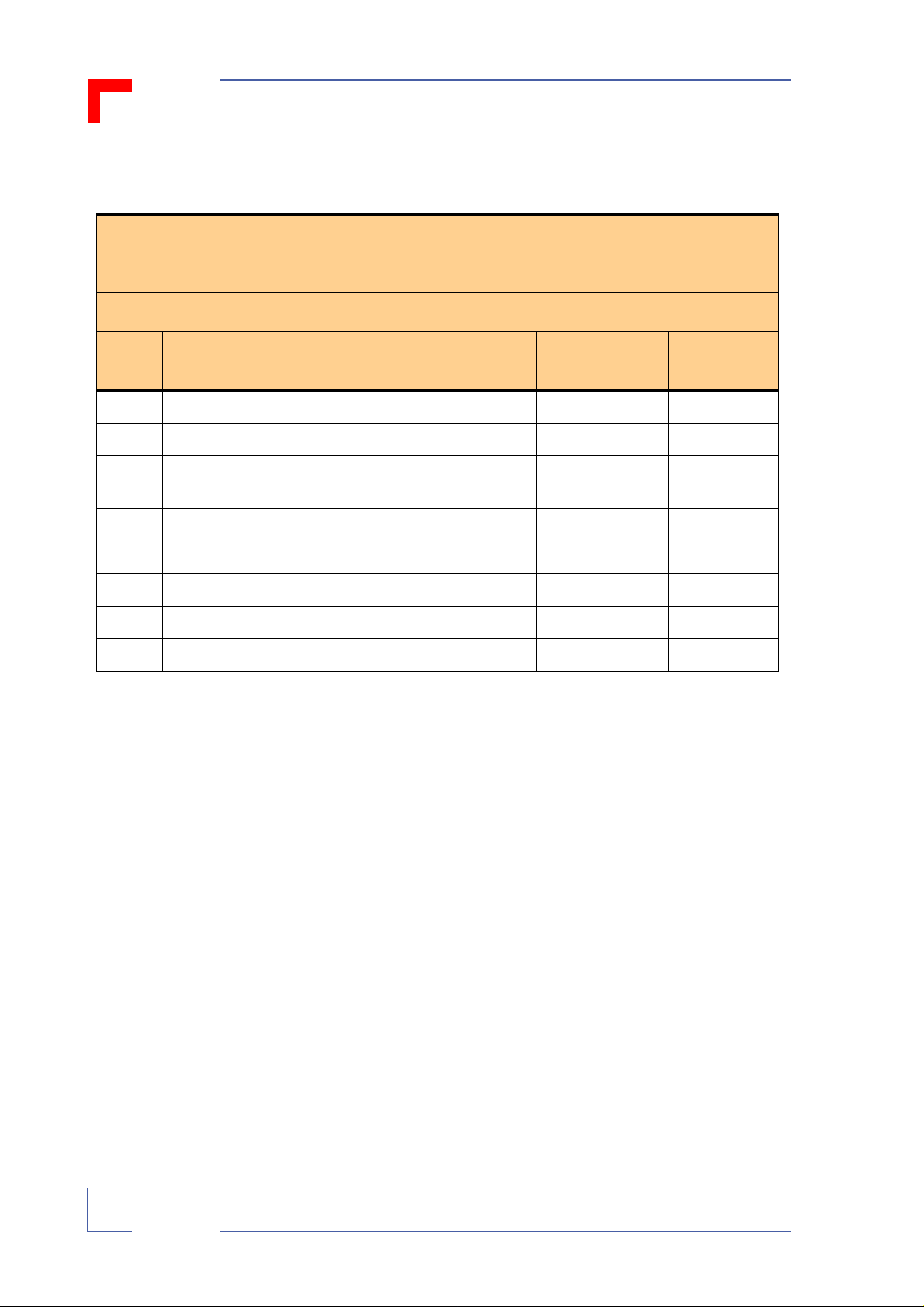
Revision History
Revision History
Manual/Product Title: PB-SIO4A
Manual ID Number: 19958
Rev.
Index
A Preliminary Jul 1992
1 Correction to Table 2.4.1 Dec 1992
1.0.1 Change to pinouts in Table 2.4.1 and additional
0200 Title Page updated Sep 1997
0300 Complete revision of manual Sep 1999
This document contains information proprietary of PEP Modular Computers. It may not be
copied or transmitted by any means, disclosed to others or stored in any retrieval system or
media, without the prior written consent of PEP Modular Computers GmbH or one of its authorized agents.
The information contained in this document is, to the best of our knowledge, entirely correct.
However, PEP Modular Computers cannot accept liability for any inaccuracies, or the consequences thereof, nor for any liability arising from the use or application of any circuit, product,
or example shown in this document.
Brief Description of Changes Board Index
note in Jumper section
Date of
Issue
Jan 1995
PEP Modular Computers reserve the right to change, modify, or improve this document or the
product described herein, as seen fit by PEP Modular Computers without further notice.
Trademarks
PEP Modular Computers, the PEP logo and “CXM” are trade marks owned by PEP Modular
Computers GmbH, Kaufbeuren (Germany). In addition, this document may include names,
company logos and trademarks, which are registered trademarks and, therefore, proprietary
of their respective owners.
ID 19958, Rev. 0300Page 0 - 4 ® PEP Modular Computers GmbH
Page 5
Explanation of Symbols
!
$
CE Conformity
This symbol indicates that the item described in this manual
is in compliance with all applied CE standards. See also the
section “Applied standards” of this manual.
Caution!
This symbol and title warn you of hazards due to electrical
shocks (> 60 V) when touching products or parts of them.
The non-observance of the measures indicated and/or prescribed by the law may cause harm to your product and/or
life/health.
See also the section “High Voltage Safety Instructions”.
PrefacePB-SIO4A
ESD-Sensitive Device!
This symbol and title inform you that electronic boards and
their components are sensitive to static electricity. Therefore, care must be taken during all handling operations and
inspections of this product, in order to ensure product integrity at all times.
Please read also the section “Special Handling and Unpacking Instructions” of this manual.
Attention!
This symbol and title emphasize aspects which, if not read
through carefully by the reader, might cause hazards to
health and/or damages to material.
Note:
This symbol and title emphasize aspects the reader should
read through carefully for his or her own advantage.
PEP Advantage
This symbol and title emphasize advantages or positive
aspects of a product and/or procedure.
Troubleshooting
This symbol and title characterize a message containing
useful information on troubleshooting and problem solving.
ID 19958, Rev. 0300 Page 0 - 5® PEP Modular Computers GmbH
Page 6
PB-SIO4APreface
For your safety
Your new PEP product was developed and tested carefully to provide all features necessary
to ensure the renown electrical safety requirements. It was also designed for a long fault-free
life. However, the life expectancy of your product can be drastically reduced by improper treatment during unpacking and installation. Therefore, in the interests of your own safety and of
the correct operation of your new PEP product, you are requested to conform with the following guidelines.
High Voltage Safety Instructions
Warning!
!
All operations on this device must be carried out by sufficiently
skilled personnel only.
Caution!
However, serious electrical shock hazards exist during all installation, repair and maintenance operations with this product. Therefore, always unplug the power cable to avoid exposure to
hazardous voltage.
Before installing your new PEP product into a system always
ensure that your mains power is switched off. This applies also to
the installation of piggybacks.
Special Handling and Unpacking Instructions
ESD Sensitive Device!
Electronic boards and their components are sensitive to static
electricity. Therefore, care must be taken during all handling operations and inspections of this product, in order to ensure product
integrity at all times.
$ Do not handle this product out of its protective enclosure while it is not used for opera-
tional purposes, unless it is otherwise protected.
$ Whenever possible, unpack or pack this product only at EOS/ESD safe work stations.
Where safe work stations are not guaranteed, it is important for the user to be electrically discharged before touching the product with his/her hands or tools. This is most
easily done by touching a metal part of your system housing.
$ It is particularly important to observe standard anti-static precautions when changing
piggybacks, ROM devices, jumper settings etc. If the product contains batteries for RTC
or memory back-up, ensure that the board is not placed on conductive surfaces, including anti-static plastics or sponges. They can cause short circuits and damage the batteries or tracks on the board.
ID 19958, Rev. 0300Page 0 - 6 ® PEP Modular Computers GmbH
Page 7

PrefacePB-SIO4A
General Instructions on Usage
$ In order to maintain PEP’s product warranty, this product must not be altered or modi-
fied in any way. Changes or modifications to the device, which are not explicitly
approved by PEP Modular Computers and described in this manual or received from
PEP Technical Support as a special handling instruction, will void your warranty.
$ This device should only be installed in or connected to systems that fulfill all necessary
technical and specific environmental requirements. This applies also to the operational
temperature range of the specific board version, which must not be exceeded. If batteries are present, their temperature restrictions must be taken into account.
$ In performing all necessary installation and application operations, please, follow only
the instructions supplied by the present manual.
$ Keep all the original packaging material for future storage or warranty shipments. If it is
necessary to store or ship the board please re-pack it as nearly as possible in the manner in which it was delivered.
$ Special care is necessary when handling or unpacking the product. Please, consult the
special handling and unpacking instruction on the previous page of this manual.
ID 19958, Rev. 0300 Page 0 - 7® PEP Modular Computers GmbH
Page 8

PB-SIO4APreface
Two Years Warranty
PEP Modular Computers grants the original purchaser of PEP products a TWO YEARS LIMITED
HARDWARE WARRANTY as described in the following. However, no other warranties that may
be granted or implied by anyone on behalf of PEP are valid unless the consumer has the
express written consent of PEP Modular Computers.
PEP Modular Computers warrants their own products, excluding software, to be free from
manufacturing and material defects for a period of 24 consecutive months from the date of
purchase. This warranty is not transferable nor extendible to cover any other users or longterm storage of the product. It does not cover products which have been modified, altered or
repaired by any other party than PEP Modular Computers or their authorized agents. Furthermore, any product which has been, or is suspected of being damaged as a result of negligence, improper use, incorrect handling, servicing or maintenance, or which has been
damaged as a result of excessive current/voltage or temperature, or which has had its serial
number(s), any other markings or parts thereof altered, defaced or removed will also be
excluded from this warranty.
If the customer’s eligibility for warranty has not been voided, in the event of any claim, he may
return the product at the earliest possible convenience to the original place of purchase,
together with a copy of the original document of purchase, a full description of the application
the product is used on and a description of the defect. Pack the product in such a way as to
ensure safe transportation (see our safety instructions).
PEP provides for repair or replacement of any part, assembly or sub-assembly at their own
discretion, or to refund the original cost of purchase, if appropriate. In the event of repair,
refunding or replacement of any part, the ownership of the removed or replaced parts reverts
to PEP Modular Computers, and the remaining part of the original guarantee, or any new
guarantee to cover the repaired or replaced items, will be transferred to cover the new or
repaired items. Any extensions to the original guarantee are considered gestures of goodwill,
and will be defined in the “Repair Report” issued by PEP with the repaired or replaced item.
PEP Modular Computers will not accept liability for any further claims resulting directly or indirectly from any warranty claim, other than the above specified repair, replacement or refunding. In particular, all claims for damage to any system or process in which the product was
employed, or any loss incurred as a result of the product not functioning at any given time, are
excluded. The extent of PEP Modular Computers liability to the customer shall not exceed the
original purchase price of the item for which the claim exists.
PEP Modular Computers issues no warranty or representation, either explicit or implicit, with
respect to its products’ reliability, fitness, quality, marketability or ability to fulfil any particular
application or purpose. As a result, the products are sold “as is,” and the responsibility to
ensure their suitability for any given task remains that of the purchaser. In no event will PEP
be liable for direct, indirect or consequential damages resulting from the use of our hardware
or software products, or documentation, even if PEP were advised of the possibility of such
claims prior to the purchase of the product or during any period since the date of its purchase.
Please remember that no PEP Modular Computers employee, dealer or agent is authorized to
make any modification or addition to the above specified terms, either verbally or in any other
form, written or electronically transmitted, without the company’s consent.
ID 19958, Rev. 0300Page 0 - 8 ® PEP Modular Computers GmbH
Page 9

PB-SIO4A Preface
Table of Contents
Chapt
Chapter
1. Introduction............................................................ 1 - 3
1.1 Product Overview.............................................1 - 3
1.2 Board Overview................................................1 - 3
1.3 Functional Block Diagram.................................1 - 5
1.4 PB-SIO4A External Interfacing.........................1 - 5
1.5 Carrier Board External Connectors ..................1 - 6
1.6 Technical Specifications...................................1 - 7
1.7 Applied Standards............................................1 - 8
1.8 Related Publications.........................................1 - 8
Chapter
1
1
2
2. Installation..............................................................2 - 3
2.1 Board Installation..............................................2 - 3
2.2 Software Installation.........................................2 - 4
Chapter
3. Configuration..........................................................3 - 3
3.1 PB-SIO4A Address Map and ID Byte...............3 - 3
3.2 VMEbus Interrupts............................................3 - 3
3.3 Jumper Settings................................................3 - 4
3.4 Pinouts..............................................................3 - 5
3
ID 19958, Rev. 0300 Page 0 - 9® PEP Modular Computers GmbH
Page 10

Preface PB-SIO4A
Chapter
4. Adapter AD-SIO4....................................................4 - 3
4.1 Product Overview .............................................4 - 3
4.2 Adapter Overview .............................................4 - 3
4
ID 19958, Rev. 0300Page 0 - 10 ® PEP Modular Computers GmbH
Page 11

PB-SIO4A
Introduction
Chapter
Introduction
1.1Product Overview..................................................................1 - 3
1.1.1Description ....................................................................1 - 3
1.1.2Features ........................................................................1 - 3
1.2Board Overview ...................................................................1 - 3
1.3Functional Block Diagram.....................................................1 - 5
1.4PB-SIO4A External Interfaceing ...........................................1 - 5
1.5Carrier Board External Connectors.......................................1 - 6
1
1.6Technical Specifications .......................................................1 - 7
1.7Applied Standards.................................................................1 - 8
1.7.1CE Compliance..............................................................1 - 8
1.7.2Mechanical Compliance.................................................1 - 8
1.7.3Environmental Tests......................................................1 - 8
1.8Related Publications.............................................................1 - 8
1.8.1General .........................................................................1 - 8
1.8.2PEP Modular Computers ..............................................1 - 8
ID 19958, Rev. 0300
Page 1 - 1® PEP Modular Computers GmbH
Page 12

This page was intentionally left blank.
® PEP Modular Computers GmbH
Page 13

PB-SIO4A Introduction
1. Introduction
1.1 Product Overview
1.1.1 Description
The PB-SIO4A is a quad (four) channel asynchronous RS422/RS485 serial piggyback
with support for full duplex RS422/RS485 transmit, receive, and RTS/CTS handshake
signals.
There are four different versions of the PB-SIO4A available:
non-optoisolated:
• RS422
• RS485
optoisolated:
• RS422
• RS485.
Any version combination can be installed on a single carrier board. Interfacing to the
PB-SIO4A depends on the type of connector provided by the carrier board or optional
adapters.
1.1.2 Features
General:
• Interrupt request line employed, interrupt vector generated by the DUART’s.
• Board ID byte for remote (software) configuration identity checking.
• Compact size, four serial ports within standard industrial I/O piggyback dimensions.
• Easy to maintain. Quick and simple replacement if required.
Hardware:
• Full electrical and mechanical compatibility with the extensive range of carrier
boards.
• All required VMEbus lines are available on the piggyback.
• Optional optoisolated driver/receiver supporting TxD and RxD.
• Optional interface adapters with four 15-pin D-sub connectors. (See Adapter ADSIO4 chapter this manual)
• Extended temperature version available for harsh industrial environments.
1.2 Board Overview
The PB-SIO4A has two connectors for interfacing to the carrier board. Connector ST101
interfaces to the CPU side of the carrier board whereas connector ST102 provides interfacing to the external interface side of the carrier board.
ID 19958, Rev. 0300 Page 1 - 3® PEP Modular Computers GmbH
Page 14

PB-SIO4A Introduction
This piggyback is fitted with DUART devices (two driver/receiver devices each handling
two of the four serial channels), as well as a GAL device containing the specific interrupt
handling logic and other features such as the I.D. number.
The optoisolated versions have eight optocouplers which are replaced with wire bridges
on the non-optoisolated versions.
For operational configuration of this piggyback there are solder jumpers located both on
the front and rear side of the board.
Figure 1-1: PB-SIO4A Board Front View (Optoisolated Version)
B51
isolation
Opto-
isolation
Opto-
isolation
DUART
DUART
2526
Transmitter
ST102
Receiver
1
2
Transmitter
Opto-
B52
Figure 1-2: PB-SIO4A Board Rear View (Optoisolated Version)
B63 B64
3
1
B60
2
3
1
B59
2
3
1
B58
2
3
1
B57
2
3
1
B56
2
3
1
B55
2
3
1
B54
2
3
1
B53
2
2 1 3
2 1 3
2 1 3
2 1 3
B68
B67
B66
B65
2930
I/F Logic
2
ST101
1
B62B61
ID 19958, Rev. 0300Page 1 - 4 ® PEP Modular Computers GmbH
Page 15

PB-SIO4A Introduction
1.3 Functional Block Diagram
Figure 1-3: Functional Block Diagram of the PB-SIO4A
DUART
ST102
DRIVER / RECEIVER
OPTOISOLATION*
DUART
* Optoisolation is optional
ST101
1.4 PB-SIO4A External Interfacing
Connection of the PB-SIO4A piggyback to external devices is a function of the specific
carrier board for the piggyback. In conjunction with the carrier board there are various
possibilities for connecting the I/O channels of the piggyback to external devices.
For the carrier boards themselves there are three types of connectors available.
Front Panel:
• 50-pin male, double row, flat-ribbon cable connector, locking
• 50-pin female, Dsub connector
I/F LOGIC
On-Board:
• 50-pin male, double row, flat-ribbon cable connector head
In conjunction with the carrier board’s connectors, there is also the possbility of providing connection to external devices using the AD-SIO4 adapter. This adapter utilizes
either of the carrier board’s flat-ribbon connectors to provide 4, 15-pin female, Dsub connectors. One connector for each channel of the PB-SIO4A. Two PB-SIO4A’s and two of
these adapters can be combined to provide 8 serial I/O channels. The AD-SIO4 is
optional and must be ordered separately. See chapter 4 of this manual for a description
of the AD-SIO4.
ID 19958, Rev. 0300 Page 1 - 5® PEP Modular Computers GmbH
Page 16

PB-SIO4A Introduction
1.5 Carrier Board External Connectors
Figure 1-4: Carrier Board External Connector Types
50
2
50-Pin Male
Front Panel
49
1
50
34
50-Pin Female
Front Panel
17
1
50
50-Pin Male
On Board
49
12
ID 19958, Rev. 0300Page 1 - 6 ® PEP Modular Computers GmbH
Page 17

PB-SIO4A Introduction
1.6 Technical Specifications
Table 1-1: PB-SIO4A Technical Specification
PB-SIO4A Specification
Standard RS422 or RS485
Number of Channels four per PB-SIO4A module
Controller two MC68681 DUART’s (one pro port pair)
Transfer Rates asynchronous: up to 115,200 Baud
Programmable Data Format • 5 ... 8 bit, plus parity
• odd, even, no parity, and force parity
• 1, 1½, and 2 stop bits
Programmable Channel Modes • normal, full duplex
• automatic echo
• local loopback
• remote loopback
Counter / Timer two 16-bit (one for each DUART)
Identification Byte E7 hex
DTACK Generation on board
Power Supply 5V DC, ± 5%
Power Consumption 0.4A, typical
Temperature Range Operating:0°C ...+70°C (Standard)
-40°C ... +85°C (Extended)
Humidity 0 ... 95% non-condensing
Dimensions Width: 48 mm (1
Length: 100 mm (3
Depth: 12 mm (1
7
/
inches)
8
15
/
inches)
16
1
/
inches)
2
Weight 110 grams
Carrier Board Interface two sets of twin row header pins providing all necessary com-
munication paths and mechanical mounting
ID 19958, Rev. 0300 Page 1 - 7® PEP Modular Computers GmbH
Page 18

PB-SIO4A Introduction
1.7 Applied Standards
1.7.1 CE Compliance
The PEP Modular Computers’ VME products comply with the requirements of the following CE-relevant standards:
• Emission EN50081-1
• Immission EN50082-2
• Electrical Safety EN60950
1.7.2 Mechanical Compliance
• Mechanical Dimensions IEEE 1101.10
1.7.3 Environmental Tests
• Vibration/Broad-Band IEC68-2-6
Random Vibration IEC68-2-64 (3U boards)
• Permanent Shock IEC68-2-29
• Single Shock IEC68-2-27
1.8 Related Publications
1.8.1 General
• VMEbus Specification, Revision C.1
• The MC68681 data sheet from Motorola
1.8.2 PEP Modular Computers
Please contact PEP Modular Computers concerning the following product manuals.
• VMOD2
• VMOD2D
• VMOD4D
• IMOD
• V642
• V662
ID 19958, Rev. 0300Page 1 - 8 ® PEP Modular Computers GmbH
Page 19

PB-SIO4A
Installation
Chapter
Installation
2.1Board Installation ..................................................................2 - 3
2.2Software Installation..............................................................2 - 4
2.2.1Driver Installation...........................................................2 - 4
2
ID 19958, Rev. 0300
Page 2 - 1® PEP Modular Computers GmbH
Page 20

This page was intentionally left blank.
® PEP Modular Computers GmbH
Page 21

PB-SIO4A Installation
$$
$$
2. Installation
2.1 Board Installation
Caution!
Switch off all power to the system and ensure that there are NO
external cables connected to the carrier board or to any optional
adapters connected to the carrier board before installing the PBSIO4A. Failure to do so could endanger your life/health and may
damage your board or system.
ESD Equipment!
Your PB-SIO4A board contains electrostatically sensitive devices.
Please observe the necessary precautions to avoid damage to
your board:
• Discharge your clothing before touching the assembly. Tools
must be discharged before use.
• Do not touch components, connector-pins or traces.
• If working at an anti-static workbench with professional discharging equipment, please do not omit to use it.
Note!
The PB-SIO4A can be installed in any free carrier board position,
and can be combined with any other type of piggyback module on a
carrier board. The only restraint here being the external interfacing
requirements, in particular, what type of cable connection is
required. It is the responsibilty of the system integrator to ensure
proper external interfacing to the PB-SIO4A.
To install a PB-SIO4A piggyback proceed as follows:
• ensure that the safety requirements indicated above are observed
• as required, ensure that the piggyback and carrier board are properly configured
(see appropriate documentation for configuration)
• if required, remove the carrier board and optional adapters from the system
• ensure the proper orientation of the PB-SIO4A to the carrier board before installing
(see appropriate documentation for orientation)
• press the piggyback onto the carrier board until fully seated
Note!
The PB-SIO4A can be securely mounted to the carrier board via
screws and stand offs as appropriate
ID 19958, Rev. 0300 Page 2 - 3® PEP Modular Computers GmbH
Page 22

PB-SIO4A Installation
• if required, repeat this process for a second piggyback on this carrier board
• install the carrier board and optional adapters as required
• connect external interfacing cables to the carrier board and optional adapters as
required
• ensure that the carrier board, optional adapters, and interfacing cables are properly
secured
2.2 Software Installation
2.2.1 Driver Installation
Drivers are available for various operating systems but are not delivered with the PBSIO4A. If required, please order the appropriate driver separately.
For installation of any required driver, please refer to the driver documentation itself.
ID 19958, Rev. 0300Page 2 - 4 ® PEP Modular Computers GmbH
Page 23

PB-SIO4A
Configuration
Chapter
Configuration
3.1 PB-SIO4A Address Map and ID Byte................................... 3 - 3
3.2 VMEbus Interrupts................................................................ 3 - 3
3.3 Jumper Settings....................................................................3 - 4
3.4 Pinouts..................................................................................3 - 5
3.4.1 PB-SIO4A/Carrier Board Connector ST101................. 3 - 5
3.4.2 PB-SIO4A/Carrier Board Connector ST102................. 3 - 6
3.4.3 PB-SIO4A to Carrier Board to AD-SIO4 ...................... 3 - 7
3
ID 19958, Rev. 0300
Page 3 - 1® PEP Modular Computers GmbH
Page 24

This page was intentionally left blank.
® PEP Modular Computers GmbH
Page 25

PB-SIO4A Configuration
3. Configuration
3.1 PB-SIO4A Address Map and ID Byte
The PB-SIO4A is addressed (odd byte access) by using the carrier board base address
and one of the following offsets for the piggyback location:
Piggyback location A ( the upper position on the carrier board)
Base Address + $01 DUART1
Base Address + $21 DUART2
Base Address + $41 ID Byte
Piggyback location B ( the lower position on the carrier board)
Base Address + $81 DUART1
Base Address + $A1 DUART2
Base Address + $C1 ID Byte
The PB-SIO4A has an ID Byte of $E7 (RS422/RS485).
3.2 VMEbus Interrupts
Each DUART device is able to issue an interrupt request (*IRQ) to the carrier board. In
the event of simultaneous interrupt requests those from DUART #1 have priority over
those from DUART #2.
The interrupt level is set by the carrier board. See the carrier board documentation for
setting of the level. The interrupt vector itself is provided by the DUART.
ID 19958, Rev. 0300 Page 3 - 3® PEP Modular Computers GmbH
Page 26

PB-SIO4A Configuration
$$
3.3 Jumper Settings
The jumper positions B53 to B69 are located on the rear side of the PB-SIO4A and are
solder bridges. Jumpers B51 and B52 are located on the front side of the PB-SIO4A and
if installed are wire bridges. They are set at the factory as required and should not be
changed.
Note!
Before operating the PB-SIO4A ensure that the B51 and B52
jumper settings are set correctly according to the application. No
external VCCext may be applied to the non-optocoupler version,
and, correspondingly, external VCCext must be applied to optocoupler versions.
Table 3-1: PB-SIO4A Jumper Settings
Jumper/Channel Setting Default Function
B53 A 2-3
B55 B
B57 C
B59 D
B54 A 2-3
B56 B
B58 C
B60 D
B61 D closed
B62 A
B63 B
B64 C
B65 C 1-2
B66 D
1-2
1-3
1-2-3
1-2
1-3
open
1-3
X receiver and driver line connected
pull-up resistor for driver line
pull-up resistor for receiver line
pull-up resistor for driver and receiver line
X receiver* and driver* line connected
pull-down resistor for driver* line
pull-down resistor for receiver* line
X 150 ohm termination resister connected
150 ohm termination resister not connected
X receiver control by driver enabled
receiver control permenant enabled
B67 A
B68 B
B51 and B52 closed
open
*
**
VCCext and GNDext from piggyback
** (This is the operational configuration
......when optocouplers are not installed.)
VCCext and GNDext from external source
** (This is the operational configuration
......when optocouplers are installed.)
ID 19958, Rev. 0300Page 3 - 4 ® PEP Modular Computers GmbH
Page 27

PB-SIO4A Configuration
3.4 Pinouts
3.4.1 PB-SIO4A/Carrier Board Connector ST101
This is a thirty pin, dual row male header connector which provides interfacing between
the PB-SIO4A and CPU side of the carrier board.
Table 3-2: Pinout of Connector ST101
Signal Pin Pin Signal
+5V (Vcc) 30 29 GND
IA1 28 27 ID0
IA2 26 25 ID1
IA3 24 23 ID2
IA4 22 21 ID3
IA5 20 19 ID4
IA6 18 17 ID5
IAS 16 15 ID6
IDS0 14 13 ID7
N/C 12 11 INT
CS 10 9 INTA
DTACK 8 7 RESET
CLK 6 5 R/W
-12V 4 3 +12V
+5V (Vcc) 2 1 GND
ID 19958, Rev. 0300 Page 3 - 5® PEP Modular Computers GmbH
Page 28

PB-SIO4A Configuration
3.4.2 PB-SIO4A/Carrier Board Connector ST102
This is a twenty-six pin, dual row male header connector which provides interfacing
between the PB-SIO4A and the application side of the carrier board.
Table 3-3: Pinout of Connector ST102
Signal Pin Pin Signal
+RxD D 26 25 +RxD D
GndE 24 23 -TxD A
+TxD A 22 21 VccE
+RxD A 20 19 -RxD A
GndE 18 17 -TxD B
+TxD B 16 15 VccE
+RxD B 14 13 -RxD B
GndE 12 11 -TxD C
+TxD C 10 9 VccE
+RxD C 8 7 -RxD C
GndE 6 5 -TxD D
+TxD D 4 3 VccE
-RxD D 2 1 -RxD D
ID 19958, Rev. 0300Page 3 - 6 ® PEP Modular Computers GmbH
Page 29

PB-SIO4A Configuration
3.4.3 PB-SIO4A to Carrier Board to AD-SIO4
Table 3-4: PB-SIO4A to Carrier Board to AD-SIO4 Pinout Table (Both Positions)
POS./
DUART
Signal ST102
Carrier
Board
P D PINS CON/CH
-RxD D 1, 2 50 24 11
+RxD D 25,26 49 23 10
VccE 3 48 22 15
+TxD D 4 47 21 8
-TxD D 5 46 20 9
2
U
P
P
E
GndE 6 45 19 1,7
-RxD C 7 44 18 11
+RxD C 8 43 17 10
VccE 9 42 16 15
+TxD C 10 41 15 8
-TxD C 11 40 14 9
GndE 12 39 13 1,7
-RxD B 13 38 12 11
+RxD B 14 37 11 10
AD-
SIO4
BU6
AD-SIO4
Front Panel
BU4 D
BU3 C
R
1
VccE 15 36 10 15
+TxD B 16 35 9 8
-TxD B 17 34 8 9
GndE 18 33 7 1,7
-RxD A 19 32 6 11
+RxD A 20 31 5 10
VccE 21 30 4 15
+TxD A 22 29 3 8
-TxD A 23 28 2 9
GndE 24 27 1 1,7
26
25
not used
not used
BU2 B
BU1 A
ID 19958, Rev. 0300 Page 3 - 7® PEP Modular Computers GmbH
Page 30

PB-SIO4A Configuration
Table 3-4: PB-SIO4A to Carrier Board to AD-SIO4 Pinout Table (Both Positions)
POS./
DUART
Signal ST102
Carrier
Board
P D PINS CON/CH
-RxD D 1, 2 24 24 11
+RxD D 25,26 23 23 10
VccE 3 22 22 15
+TxD D 4 21 21 8
-TxD D 5 20 20 9
2
L
O
W
E
GndE 6 19 19 1,7
-RxD C 7 18 18 11
+RxD C 8 17 17 10
VccE 9 16 16 15
+TxD C 10 15 15 8
-TxD C 11 14 14 9
GndE 12 13 13 1,7
-RxD B 13 12 12 11
+RxD B 14 11 11 10
AD-
SIO4
BU6
AD-SIO4
Front Panel
BU4 D
BU3 C
R
1
VccE 15 10 10 15
+TxD B 16 9 9 8
-TxD B 17 8 8 9
GndE 18 7 7 1,7
-RxD A 19 6 6 11
+RxD A 20 5 5 10
VccE 21 4 4 15
+TxD A 22 3 3 8
-TxD A 23 2 2 9
GndE 24 1 1 1,7
Legend: POS(ition)/DUART, P, D; CON/CH
where: P = position on carrier board
D = DUART
CON = connector
CH = channel
BU2 B
BU1 A
ID 19958, Rev. 0300Page 3 - 8 ® PEP Modular Computers GmbH
Page 31

PB-SIO4A
Adapter AD-SIO4
Chapter
Adapter AD-SIO4
4.1 Product Overview................................................................. 4 - 3
4.2 Adapter Overview................................................................. 4 - 3
4
ID 19958, Rev. 0300
Page 4 - 1® PEP Modular Computers GmbH
Page 32

This page was intentionally left blank.
® PEP Modular Computers GmbH
Page 33

PB-SIO4A Adapter AD-SIO4
4. Adapter AD-SIO4
4.1 Product Overview
The AD-SIO4 is a special adapter designed to provide front panel connection to the PBSIO4A using 15-pin Dsub connectors as opposed to the 50-pin connector provided by
the carrier board.
This adapter consists of a separate, 8 HP front panel with four, 15-pin female Dsub connectors mounted on the front side for external device connection, and two, 24-pin, male
dual row connectors for internal connection to the PB-SIO4A carrier board. Connection
from the carrier board to the adapter is done via a 50-way, flat band cable with a 50-pin
dual row female connector for the carrier board, and two, 24-pin dual row female connectors for connection to the adapter. This cable allows for the connection of two PBSIO4A’s to two AD-SIO4’s where pins 25 and 26 are not used. See Table 3-4 for the
pinout of this cable.
4.2 Adapter Overview
Figure 4-1: Front View of the AD-SIO4 with Dsub Pin Layout
BU2 BU3
Channel
B
BU1
Channel
A
Channel
C
BU4
Channel
D
VccE 15
- RxD 11
+RxD 10
Pin 15 is for use only with
the optocoupler version
of the PB-SIO4A.
- TxD 9
8 + TxD
7 Gnd
1 Gnd
ID 19958, Rev. 0300 Page 4 - 3® PEP Modular Computers GmbH
Page 34

PB-SIO4A Adapter AD-SIO4
$$
$$
Figure 4-2: Rear View of the AD-SIO4
24 23
BU5
12
24 23
BU6
12
Connector BU6 is for use with the PB-SIO4A. Connector BU5 is reserved for use with
the PB-SIO4, another serial interface piggyback from PEP.
RESERVED DO NOT USE
(see note below)
USE FOR PB-SIO4A
Note!
Always ensure that the correct connector of the adapter cable is
connected to BU6. See Table 3-4 for cable pinout.
Note!
For use with the PB-SIO4A ensure that there is no cable connected
to BU5. Failure to comply with this will result in misfunctioning and
possible damage to equipment.
ID 19958, Rev. 0300Page 4 - 4 ® PEP Modular Computers GmbH
 Loading...