

Page 1

CPCI
Power Supply
Manual
PRODUCT DOCUMENTATION
PD14
CP3-SVE-P200DC-24V
Reference ID:24139 PD14, Rev. 02
June 28, 2013
Page 2
PD14: CP3-SVE-P200DC-24V CPCI Power Supply
Revision History
Manual / Product Title: CPCI Power Supply Manual:
Product Documentation:
CP3-SVE-P200DC-24V
Reference ID: 24139 PD14
Rev. Brief Description of Changes Date of Issue
01 Initial issue Jan. 22, 2009
02 Updated specifications for Environmental parameters Jun. 28, 2013
Imprint
Kontron Europe GmbH may be contacted via the following:
MAILING ADDRESS TELEPHONE AND E-MAIL
Kontron Europe GmbH +49 (0) 800-SALESKONTRON
Sudetenstraße 7 sales@kontron.com
D - 87600 Kaufbeuren Germany
For information about other
Kontron products, please
visit our Internet web site: www.kontron.com
Disclaimer
Copyright © 2009-2013 Kontron AG. All rights reserved. All data is for information purposes
only and not guaranteed for legal purposes. Information has been carefully checked and is believed to be accurate; however, no responsibility is assumed for inaccuracies. Kontron and the
Kontron logo and all other trademarks or registered trademarks are the property of their respective owners and are recognized. Specifications are subject to change without notice.
Page 2
RID 24139 PD14, Rev.02
Page 3
CPCI Power Supply PD14: CP3-SVE-P200DC-24V
1. Introduction
The specific product description provided with this product documentation is part of the PEP’s
CPCI Power Supply manual. For further information, in particular regarding general details as
well as safety and warranty statements, refer to the CPCI Power Supply Manual, ID 24139.
2. 200W P-Type Power Supply Unit
The main features of the 3U P-type, 18V ... 36V DC input, 200W output DC/DC power supply
unit CP3-SVE-P200DC-24V are described in the following table:
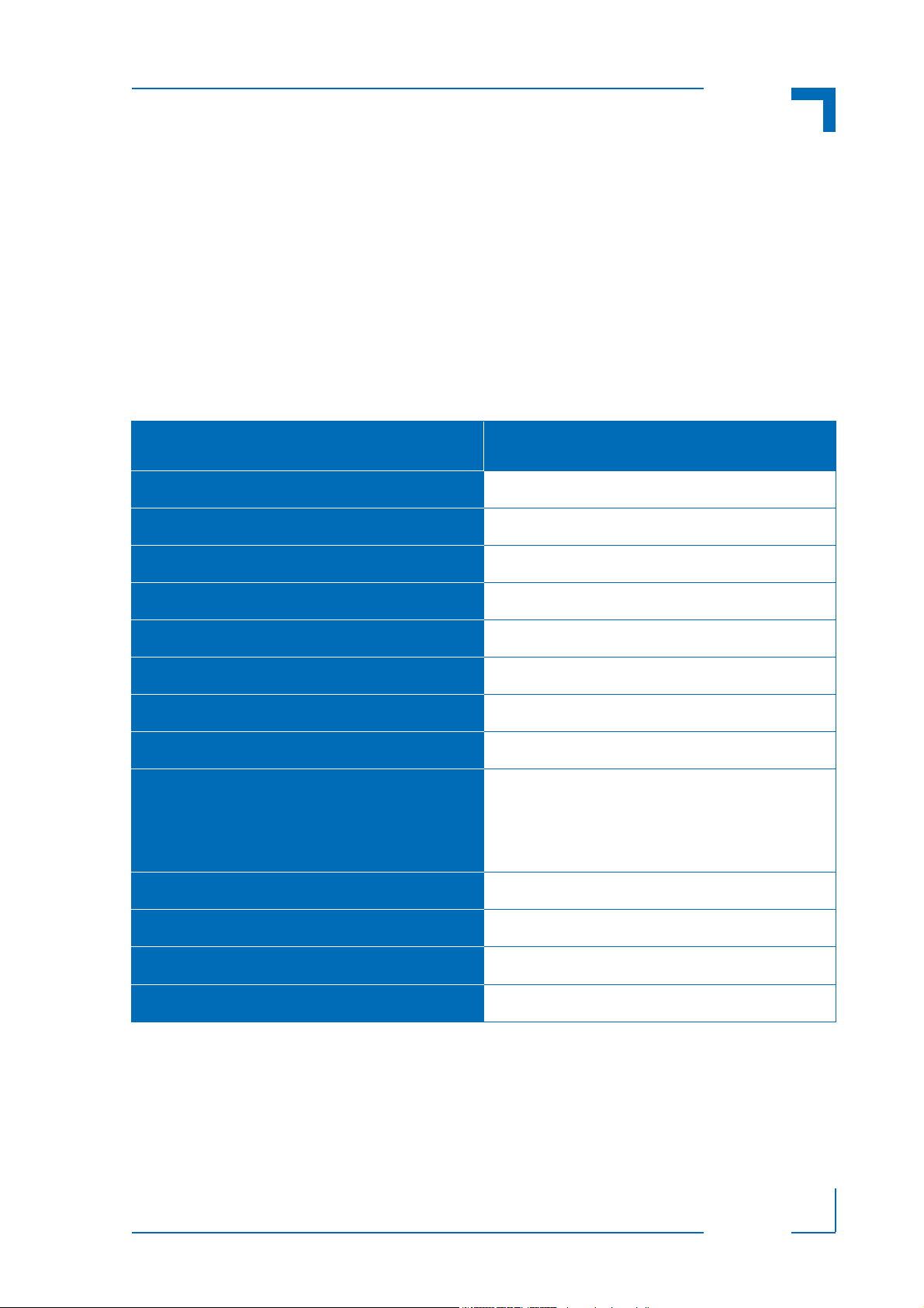
Table 1: Distinctive Features of Power Supply Unit CP3-SVE-P200DC-24V
FEATURE SPECIFICATION
Form Factor
Front Panel Size
Mechanics
Plug-In Compatibility
Power Supply Connector
Input Voltage
Voltage Switching
Output Power
Output Voltages / Currents
Cooling
Redundant Supply Capability
3U
40.34 mm x 128.6 mm
19” rack
Yes
Positronic 47-pin connector
18 … 36 V DC
Widerange
200W with 250 LFM forced-air cooling (ca. 1.3 m/s)
V1 = + 5V at 25 A
V
= + 3.3 V at 36 A
2
= + 12 V at 3 A
V
3
V
= - 12 V at 0.5 A
4
250 LFM forced-air cooling (ca. 1.3 m/s)
Always
Status Indication
Special Feature(s)
RID 24139 PD14, Rev.02
LED’s for input good and power fail
None
Page 3
Page 4

PD14: CP3-SVE-P200DC-24V CPCI Power Supply
2.1 Mechanical Specifications
Figure 1: View of Power Supply Unit CP3-SVE-P200DC
Page 4
RID 24139 PD14, Rev.02
Page 5

CPCI Power Supply PD14: CP3-SVE-P200DC-24V
6.671" (169.4mm)
1.6" (40.6mm)
0.1" (2.54mm)
6.399" (162.5mm)
3U x 8HP
ALARM
POWER
Figure 2: Power Supply Dimensions
RID 24139 PD14, Rev.02
Page 5
Page 6

PD14: CP3-SVE-P200DC-24V CPCI Power Supply
1
3
5
7
9
11
13
15
17
19
2
4
6
8
10
12
14
16
18
20
21 22 23
24 25 26
27 28 29
30 31 32
33 34 35
36 37 38
39
40 41
42 43 44
45
46
47
2.2 Power Supply Connector
Figure 3: Orientation of the Positronic
P-47 Power Supply Connector
The DC input voltage to the power supply unit and the V1 ... V4 output voltages
from the power supply unit to the backplane are connected via a 47-pin Positronic male power supply connector.
For the pinouts of the Positronic P-47
power supply connector please refer to
the following table.
3
2
1
Page 6
RID 24139 PD14, Rev.02
Page 7

CPCI Power Supply PD14: CP3-SVE-P200DC-24V
Table 2: Positronic 47-Pin Connector Pinout
PIN SIGNAL NAME DESCRIPTION PIN SIGNAL NAME DESCRIPTION
1 - 4 V1 V1 OUTPUT (+5V) 32 NC NOT CONNECTED
5 - 12 RTN V1 and V2 RETURN 33 V2 SENSE V2 REMOTE SENSE
13 - 18 V2 V2 OUTPUT (+3.3V) 34 S RTN SENSE RETURN
19 RTN V3 RETURN 35 V1 SHARE V1 CURRENT SHARE
20 V3 V3 OUTPUT (+12V) 36 V3 SENSE Not Used
21 V4 V4 OUTPUT (-12V) 37 IPMB_SCL Res. f. SM Bus
22 RTN SIGNAL RETURN 38 DEG# DEGRADE SIGNAL
23 RESERVED RESERVED 39 INH# INHIBIT
24 RTN V4 RETURN 40 IPMB_SDA Res. f. SM Bus
25 GA0 GA Bit 0 41 V2 SHARE V2 CURRENT SHARE
26 RESERVED RESERVED 42 FAL# FAIL SIGNAL
27 EN# ENABLE 43 IPMB_PWR Res. f. SM Bus
28 GA1 GA Bit 1 44 V3 SHARE V3 CURRENT SHARE
29 NC NOT CONNECTED 45 CGND CHASSIS GROUND
(safety ground)
30 V1SENSE V1 REMOTE SENSE 46 +DCIN + DC Input
31 GA2 GA Bit 2 47 -DCIN - DC Input
2.3 Installation
Thanks to its plug-in compatibility this P-type power supply unit allows for an easy installation,
by which the power supply unit’s male Positronic 47-pin power connector is inserted into the
backplane’s mating female connector without the need of any intermediate adaptation.
Warning!
If this type of power supply is removed for any reason from an operating system, do not reinstall immediately. Wait 1 to 2 minutes before
reinstalling. Failure to comply with this may result in an Output Failure
indication on the power supply. This is due to an internal protection
feature of the power supply which requires time to cool down before
the power supply is put back into operation.
RID 24139 PD14, Rev.02
Page 7
Page 8

PD14: CP3-SVE-P200DC-24V CPCI Power Supply
2.4 Electrical Specifications
INPUT
PARAMETER CONDITIONS / DESCRIPTION MIN NOM MAX UNITS
Input Voltage - DC Continuous input range. 18 36 VDC
Hold-up Time From 24 VDC input None ms
Input Current At full rated load A
Input Protection Non-user serviceable, internally-located input line fuse.
Inrush Surge Current Internally limited by thermistor and electronic switch. 20 A
Operating Frequency Switching frequency of main output transformer. 125 145 kHz
OUTPUT
PARAMETER CONDITIONS/DESCRIPTION MIN NOM MAX UNITS
Efficiency Full rated load, 24 VDC input >= 83 %
Minimum Load; V1,
V2, V3
Minimum Load, V3 Minimum load on V3 required to maintain regulation on V4 None A
Ripple and Noise Full load, 20 MHz bandwidth See Regulation table
Output Power 250 LFM forced-air cooling (ca. 1.3 m/s) 200 W
Overshoot /
Undershoot
Regulation Varies by output. Total regulation includes: line changes
Turn-on Delay Time required for initial output voltage stabilization 1 sec
Initial Setting Accuracy ±1 %
Minimum load required to maintain regulation with no
load on V4
Output voltage overshoot / undershoot at turn-on 0 %
over the specified input range, changes in load starting at
50% load and changing to 100% load
None A
See Regulation table
REGULATION
OUTPUT
VOLTAGE
ADJUSTMENT
RANGE
OUTPUT
CURRENT
LINE
REGULATION
LOAD
REGULATION
RIPPLE & NOISE
pk-pk
V1 +5V N/A 25A 0.5% 1% < 60 mV
V2 +3.3V N/A 36A 0.5% 1% < 60 mV
V3 +12V N/A 3A 0.5% 1% < 120 mV
V4 -12V N/A 0.5A 0.5% 1% < 120 mV
Page 8
RID 24139 PD14, Rev.02
PP
PP
PP
PP
Page 9

CPCI Power Supply PD14: CP3-SVE-P200DC-24V
PROTECTION AND CONTROL
PARAMETER CONDITIONS/DESCRIPTION MIN NOM MAX UNITS
Overvoltage
Protection
Overload Protection Fully protected against output overload and short cir-
Overtemperature
Protection
Power Fail (FAL#) TTL compatible signal, open collector active low sig-
Current Share Accuracy of shared current with up to 6 parallel units
Remote Sense Available on V1, V2, and V3. Total voltage compensa-
Inhibit (INH#) TTL-compatible signal inhibited with GND or TTL "0". Available
Enable (EN#) Contact closure to external ground to start unit. On
Overtemperature
Warning (DEG#)
Latch style overvoltage protection. 125 %Vnom
Available
cuit. Automatic recovery upon removal of overload
condition.
System shutdown due to excessive internal temperature, automatic reset.
nal. Indicates any output below 90% and/or a low
input <36VDC.
of the same type of power supply. Single wire current
share on V1, V2, and V3.
tion for cable losses with respect to the main output.
shortest pin (last make, first break).
Provides warning when power supply temperature
exceeds rating. TTL-compatible open.
(activated before thermal shutdown)
Available
Available
Available
Available
10 %
±150 mV
Front Panel LED
Status Indicators
Input OK (Green), Output Failure (Red). In redundant
setups, Output Failure may also indicate that there is
no main power input to the power supply.
Available
SAFTEY, REGULATORY, AND EMI
PARAMETER CONDITIONS/DESCRIPTION MIN NOM MAX UNITS
Agency Approvals UL1950, cUL1950, EN60950 (TÜV). Approved
Dielectric Withstand
Voltage
Electromagnetic
Interference
ESD Susceptibility Per EN61000-4-2, level 4. 8 kV
Radiated
Susceptibility
EFT/Burst Per EN61000-4-4, level 3. ± 2 kV
Input Surge Per EN61000-4-5, level 3. Line to Line
Input to Output per EN60950. 4243 VDC
EN55022 / CISPR 22 Conducted:
Radiated:
Per EN61000-4-3, level 3. 10 V/m
Line to Ground
A
A
1
2
Class
kV
RID 24139 PD14, Rev.02
Page 9
Page 10

PD14: CP3-SVE-P200DC-24V CPCI Power Supply
SAFTEY, REGULATORY, AND EMI
PARAMETER CONDITIONS/DESCRIPTION MIN NOM MAX UNITS
Conducted
Disturbance
Insulation
Resistance
Per EN61000-4-6, level 2. 3 V
Input to Output. tbd MΩ
ENVIRONMENTAL
PARAMETER CONDITIONS/DESCRIPTION MIN NOM MAX UNITS
Altitude Operating.
Non-Operating.
Operating
Temperature
Storage
Temperature
Relative Humidity Non-Condensing. 5 93 %RH
Shock Peak acceleration. 20 GPK
Vibration Random vibration, 10 Hz to 500 Hz, 3 axis. 1.9 GRMS
With 250 LFM forced-air cooling At 100% load:
Derate linearly above 50°C by 5W per °C. At 50%
load:
- 20 + 55
+ 70
- 40 + 85 °C
ASL Ft.
°C
Warning!
Adequate thermal cooling of the power supply must be ensured.
Therefore do not obstruct or hinder cooling air circulation or heat conduction within the power supply or surrounding equipment.
Failure to comply with this warning may result in damage to your
equipment.
Page 10
RID 24139 PD14, Rev.02
 Loading...