

Page 1

» User Guide «
CP3003-SA/CP3003-V
uEFI BIOS
Doc. ID: 1053-4014, Rev. 2.0
July 29, 2013
If it’s embedded, it’s Kontron.
D R A F T — F O R I N T E R N A L U S E O N L Y
Page 2

Preface CP3003-SA/CP3003-V uEFI BIOS
Revision History
Publication Title:
Doc. ID: 1053-4014
Rev. Brief Description of Changes Date of Issue
1.0 Initial issue based on the uEFI BIOS version R11 29-Jul-2013
2.0 Added description for the CP3003-V based on the uEFI BIOS version R11
CP3003-SA/CP3003-V uEFI BIOS User Guide
29-Jul-2013
Imprint
Kontron Europe GmbH may be contacted via the following:
MAILING ADDRESS TELEPHONE AND E-MAIL
Kontron Europe GmbH +49 (0) 800-SALESKONTRON
Sudetenstraße 7 sales@kontron.com
D - 87600 Kaufbeuren Germany
For further information about other Kontron products, please visit our Internet web site:
www.kontron.com.
Disclaimer
Copyright © 2013 Kontron AG. All rights reserved. All data is for informatio n purposes only and
not guaranteed for legal purposes. Information has been carefully checked and is believed to
D R A F T — F O R I N T E R N A L U S E O N L Y
be accurate; however, no responsibility is assumed for inaccuracies. Kontron and the Kontron
logo and all other trademarks or registered trademarks are the property of their respective owners and are recognized. Specifications are subject to change without notice.
Page ii ID 1053-4014, Rev. 2.0
Page 3

CP3003-SA/CP3003-V uEFI BIOS Preface
Table of Contents
Revision History .........................................................................................................ii
Imprint ........................................................................................................................ii
Disclaimer ..................................................................................................................ii
Table of Contents ......................................................................................................iii
1. Starting uEFI BIOS Setup .............................................................3
1.1 Main Setup Menu ......................................................................................... 4
1.2 Navigation ....................................................................................................5
2. Main Setup .....................................................................................9
2.1 BIOS Information .......................................................................................... 9
2.2 Memory Information .....................................................................................9
2.3 Trusted Computing ..................................................................................... 10
2.3.1 Configuration .....................................................................................10
2.3.1.1 TPM Support (CP3003-SA) ....................................................... 10
2.3.2 Current Status Information ................................................................. 10
2.4 CPU Configuration ......................................................................................11
2.4.1 CPU Configuration ..............................................................................11
2.4.2 Max Freq Ratio ...................................................................................11
2.5 Firmware Update Configuration .................................................................12
2.5.1 Me FW Image Re-Flash .....................................................................12
2.6 USB Configuration ..................................................................................... 13
2.6.1 USB Configuration ............................................................................. 13
2.6.1.1 USB Devices .............................................................................13
2.6.1.2 Legacy USB Support ................................................................. 13
2.6.1.3 USB3.0 Support ........................................................................14
2.6.1.4 XHCI Hand-Off ..........................................................................14
2.6.1.5 EHCI Hand-Off ..........................................................................14
2.6.2 USB Hardware Delays and Time-outs ............................................... 15
2.6.2.1 USB Transfer Timeout ...............................................................15
2.6.2.2 Device Reset Timeout ............................................................... 15
2.6.2.3 Device Power-up Delay ............................................................. 15
ID 1053-4014, Rev. 2.0 Page iii
Page 4

Preface CP3003-SA/CP3003-V uEFI BIOS
2.7 Serial Port Console Redirection ..................................................................16
2.7.1 COM0 .................................................................................................16
2.7.1.1 Console Redirection ..................................................................16
2.7.1.2 Console Redirection Settings ....................................................16
2.7.2 COM1 .................................................................................................17
2.7.2.1 Console Redirection ..................................................................17
2.7.2.2 Console Redirection Settings ....................................................17
2.7.3 Serial Port for Out-of-Band Management/Windows EMS ..................20
2.7.3.1 Console Redirection ..................................................................20
2.7.3.2 Console Redirection Settings ....................................................20
2.8 System Language .......................................................................................22
2.9 System Date ...............................................................................................22
2.10 System Time ...............................................................................................22
2.11 Access Level ...............................................................................................22
3. Boot Setup ..................................................................................25
3.1 Boot Configuration ......................................................................................25
3.1.1 Setup Prompt Timeout .......................................................................25
3.1.2 Bootup NumLock State ......................................................................25
3.1.3 Quiet Boot ..........................................................................................26
3.1.4 Fast Boot ............................................................................................26
3.1.5 CSM16 Module Version .....................................................................26
3.1.6 GateA20 Active ..................................................................................26
3.1.7 Option ROM Messages ......................................................................26
3.1.8 Interrupt 19 Capture ...........................................................................27
3.1.9 CSM Support ......................................................................................27
3.2 Boot Option Priorities ..................................................................................27
3.2.1 Boot Option #1..2 ...............................................................................27
3.2.2 Hard Drive BBS Priorities ...................................................................27
4. Security Setup ............................................................................31
4.1 Administrator Password ..............................................................................32
4.2 User Password ...........................................................................................32
Page iv ID 1053-4014, Rev. 2.0
Page 5

CP3003-SA/CP3003-V uEFI BIOS Preface
4.3 HDD Security Configuration ....................................................................... 32
4.4 Remember the Password ........................................................................... 32
5. Save & Exit ...................................................................................35
5.1 Save Changes and Exit .............................................................................. 35
5.2 Discard Changes and Exit .......................................................................... 35
5.3 Save Changes and Reset ..........................................................................35
5.4 Discard Changes and Reset ......................................................................36
5.5 Save Changes (Save Options) ................................................................... 36
5.6 Discard Changes (Save Options) ...............................................................36
5.7 Restore Defaults (Save Options) ................................................................ 36
5.8 Save as User Defaults (Save Options) .......................................................36
5.9 Restore User Defaults (Save Options) ....................................................... 36
5.10 Boot Override .............................................................................................36
6. The uEFI Shell ..............................................................................39
6.1 Introduction, Basic Operation ..................................................................... 39
6.1.1 Shell Startup ...................................................................................... 39
6.2 Kontron-Specific uEFI Shell Commands .................................................... 40
6.2.1 kBiosRevision uEFI Shell Command .................................................41
6.2.2 kboardconfig uEFI Shell Command ................................................... 42
6.2.3 kboardinfo uEFI Shell Command .......................................................49
6.2.4 kboot uEFI Shell Command ...............................................................51
6.2.5 kbootnsh uEFI Shell Command .........................................................52
6.2.6 kclearnvram uEFI Shell Command .................................................... 53
6.2.7 kflash uEFI Shell Command .............................................................. 54
6.2.8 kmkramdisk uEFI Shell Command .................................................... 55
6.2.9 kpassword uEFI Shell Command ......................................................56
6.2.10 kresetconfig uEFI Shell Command ................................................... 57
6.2.11 kSettings uEFI Shell Command ......................................................... 58
6.2.12 kwdt uEFI Shell Command ................................................................ 59
6.3 uEFI Shell Scripting .................................................................................... 60
6.3.1 Startup Scripting ................................................................................ 60
ID 1053-4014, Rev. 2.0 Page v
Page 6

Preface CP3003-SA/CP3003-V uEFI BIOS
6.3.2 Create a Startup Script .......................................................................60
6.3.3 Examples of Startup Scripts ...............................................................60
6.3.3.1 Automatic Booting from USB Flash Drive ..................................60
6.3.3.2 Execute Shell Script on Other Harddrive ...................................61
6.3.3.3 Enable Watchdog and Control PXE Boot ..................................61
6.3.3.4 Handling the Startup Script in the Flash Bank ...........................62
7. Updating the uEFI BIOS ............................................................. 65
7.1 uEFI BIOS Fail-Over Mechanism ...............................................................65
7.2 Updating Procedure ....................................................................................65
7.3 uEFI BIOS Recovery ..................................................................................65
7.4 Determining the Active Flash ......................................................................65
Page vi ID 1053-4014, Rev. 2.0
Page 7

CP3003-SA/CP3003-V uEFI BIOS Starting uEFI BIOS Setup
Chapter 1
1
Starting uEFI BIOS Setup
ID 1053-4014, Rev. 2.0 Page 1
D R A F T — F O R I N T E R N A L U S E O N L Y
Page 8

Starting uEFI BIOS Setup CP3003-SA/CP3003-V uEFI BIOS
This page has been intentionally left blank.
D R A F T — F O R I N T E R N A L U S E O N L Y
Page 2 ID 1053-4014, Rev. 2.0
Page 9

CP3003-SA/CP3003-V uEFI BIOS Starting uEFI BIOS Setup
Enter Password
1. Starting uEFI BIOS Setup
The CP3003-SA/CP3003-V is provided with a Kontron-customized, pre-installed and configured version of Aptio® (referred to as uEFI BIOS in this manual), AMI’s next generation BIOS
firmware based on the Unified Extensible Firmware Interface (uEFI) specification and the Intel® Platform Innovation Framework for EFI. This uEFI BIOS provides a variety of new and enhanced functions specifically tailored to the hardware features of the CP3003-SA/CP3003-V.
To take advantage of these functions, the uEFI BIOS comes with a Setup program which provides quick and easy access to the individual function settings for control or modification of the
uEFI BIOS configuration.
The Setup program allows the accessing of various menus which provide functions or access
to sub-menus with more specific functions of their own. The individual menus and the configurable functions are described in this guide.
To start the uEFI BIOS Setup program, follow the steps below:
1. Power on the board.
2. Wait until the first characters appear on the screen (POST messages or splash screen).
3. Press the <DEL> or <F2> key.
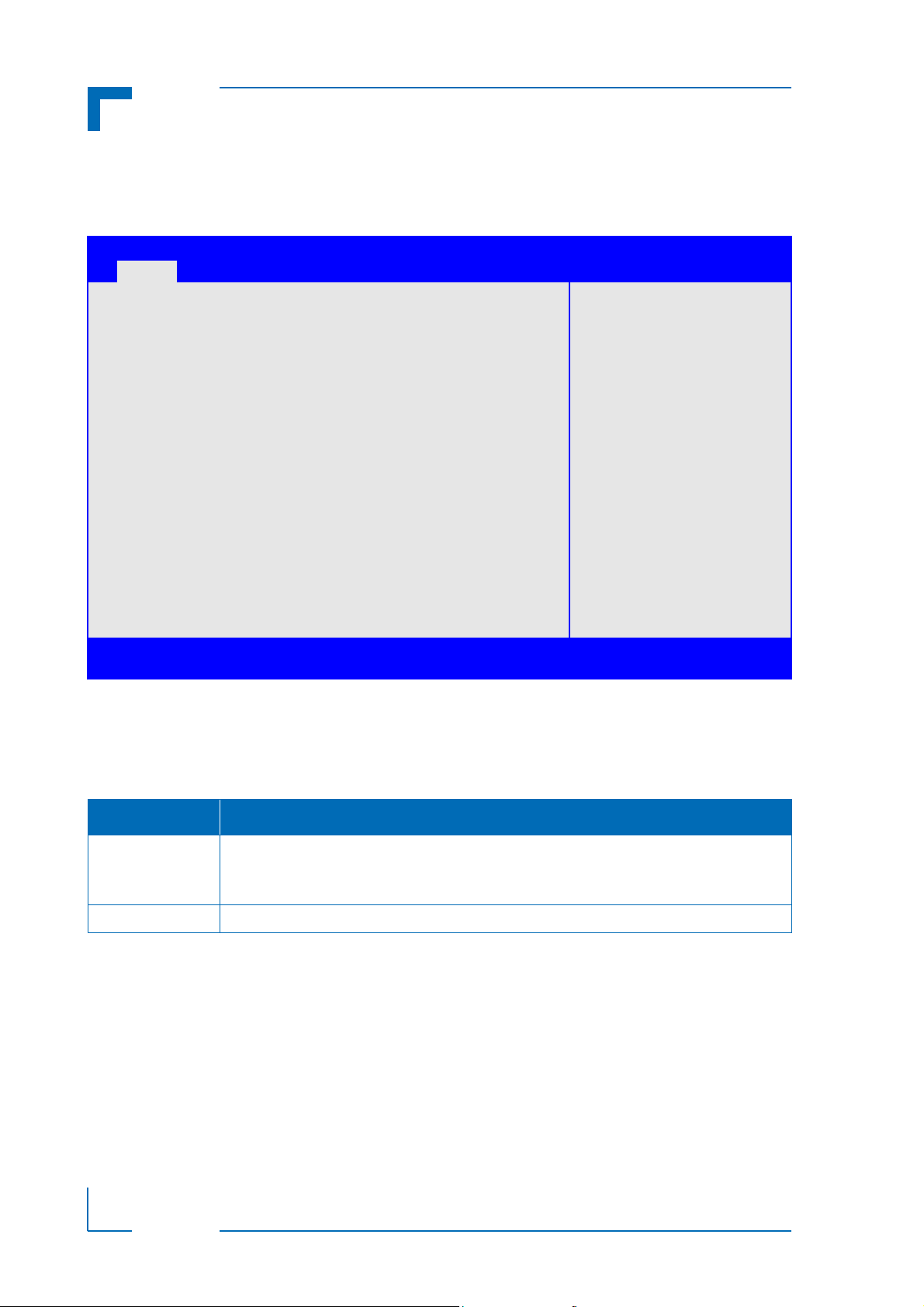
4. If the uEFI BIOS is password-protected, a window such as the one below will appear:
Enter either the User password or the Administrator p assword (refer to Chap ter 4, Security Setup, for further information), press <RETURN>, and proceed with step 5.
5. A Setup menu with the following token attributes will appear.
The currently active menu and the currently active uEFI BIOS Setup item a re highlighted
in white.
D R A F T — F O R I N T E R N A L U S E O N L Y
ID 1053-4014, Rev. 2.0 Page 3
Page 10

Starting uEFI BIOS Setup CP3003-SA/CP3003-V uEFI BIOS
1.1 Main Setup Menu
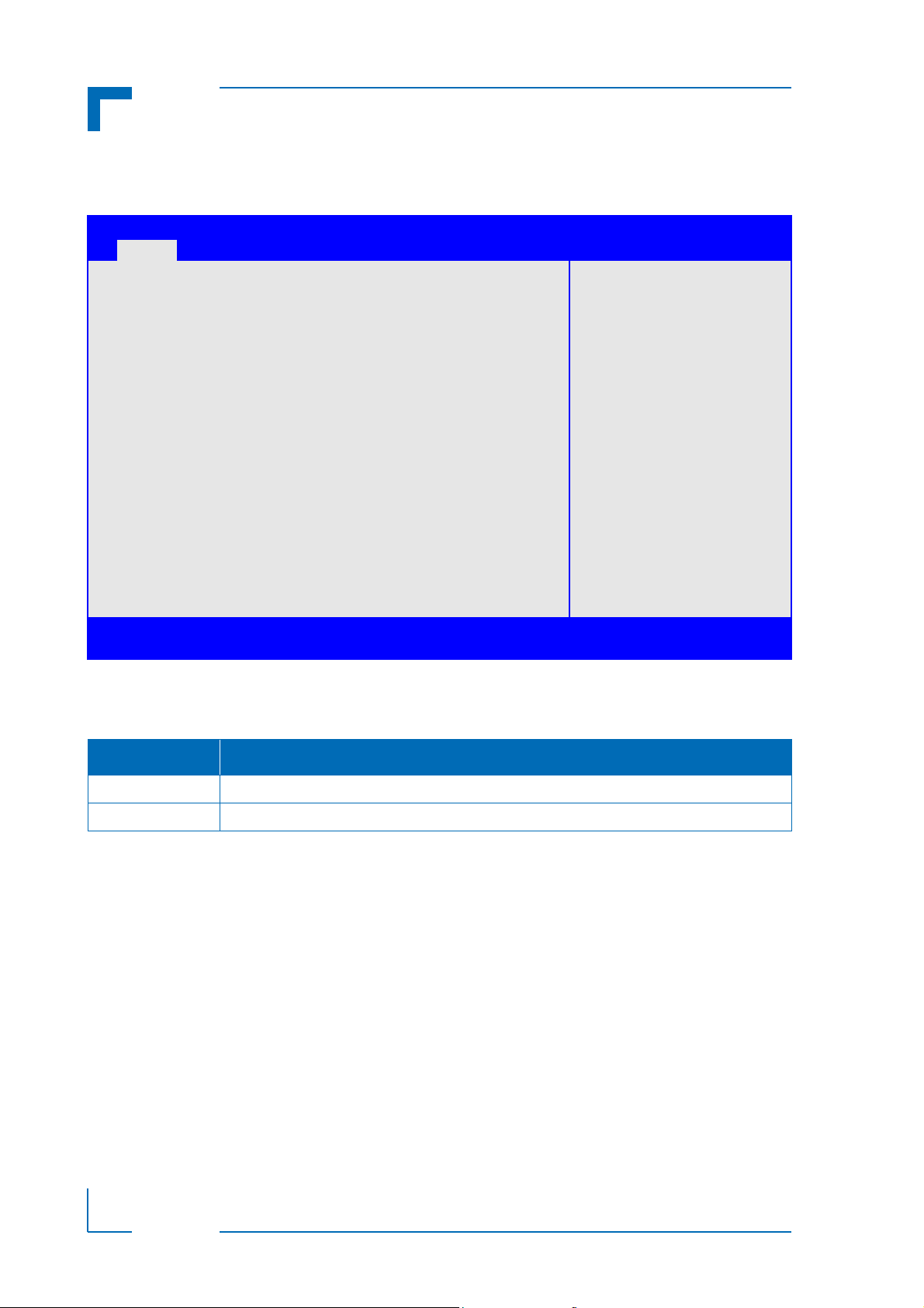
The Main setup menu is the first screen that appears after starting the Setup program.
At the top of this screen and all of the other major screens, there is a setup menu selection bar ,
which permits access to all of the other major setup menus. These menu s are selected via t he
left-right arrow keys.
All setup menu screens have two main frames. The left frame displays all the functions that can
be configured. They are displayed in blue. Functions displayed in gray provide information
about the status or the operational configuration.
The right frame displays the key legend. Above the key legend there is an area reserved for a
text message. When a function is selected in the left frame, it is displayed in white. Often a text
message will accompany it.
Aptio Setup Utility - Copyright (C) 2011 American Megatrends, Inc.
Main Boot Security Save & Exit
Tit l e (b lac k)
Read only field (grey) value
Setup item (blue) [value]
Pointer to a subordinate menu
: Select Screen
: Select Item
Enter: Select
+/-: Change Opt.
F1: General Help
F2: Previous Values
F3 Optimized Defaults
F4: Save & Exit
ESC: Exit
Version 2.14.1219. Copyright (C) 2011 American Megatrends, Inc.
D R A F T — F O R I N T E R N A L U S E O N L Y
Page 4 ID 1053-4014, Rev. 2.0
Page 11

CP3003-SA/CP3003-V uEFI BIOS Starting uEFI BIOS Setup
1.2 Navigation
The CP3003-SA/CP3003-V uEFI BIOS setup program uses a hot key-based navigation system. A hot key legend is located in the right frame on most setup screens.The following table
provides information concerning the usage of these hot keys.
HOT KEY DESCRIPTION
<F1> The <F1> key is used to invoke the General Help window.
<F2> The <F2> key is used to restore the previous values.
<F3> The <F3> key is used to load the defaults.
<F4> The <F4> key is used to save the current settings and exit the uEFI BIOS Setup.
Right/Left The Right and Left <Arrow> keys are used to select a major Setup screen.
For example: Main Screen, Advanced Screen, Chipset Screen, etc.
Up/Down The Up and Down <Arrow> keys are used to select a Setup function or a sub-screen.
+ - Plus/Minus The Plus and Minus <Arrow> keys are used to change the field value of a particular Setup
function, for example, system date and time.
<ESC> The <ESC> key is used to exit a menu or the uEFI BIOS Setup.
Pressing the <ESC> key in a sub-menu causes the next higher menu level to be displayed.
When the <ESC> key is pressed in a major Setup menu, the uEFI BIOS Setup is terminated
without saving any changes made.
<Enter> The <Enter> key is used to execute a command or select a menu.
ID 1053-4014, Rev. 2.0 Page 5
D R A F T — F O R I N T E R N A L U S E O N L Y
Page 12

Starting uEFI BIOS Setup CP3003-SA/CP3003-V uEFI BIOS
This page has been intentionally left blank.
D R A F T — F O R I N T E R N A L U S E O N L Y
Page 6 ID 1053-4014, Rev. 2.0
Page 13

CP3003-SA/CP3003-V uEFI BIOS Main Setup
Chapter 1
2
Main Setup
ID 1053-4014, Rev. 2.0 Page 7
D R A F T — F O R I N T E R N A L U S E O N L Y
Page 14

Main Setup CP3003-SA/CP3003-V uEFI BIOS
This page has been intentionally left blank.
D R A F T — F O R I N T E R N A L U S E O N L Y
Page 8 ID 1053-4014, Rev. 2.0
Page 15

CP3003-SA/CP3003-V uEFI BIOS Main Setup
2. Main Setup
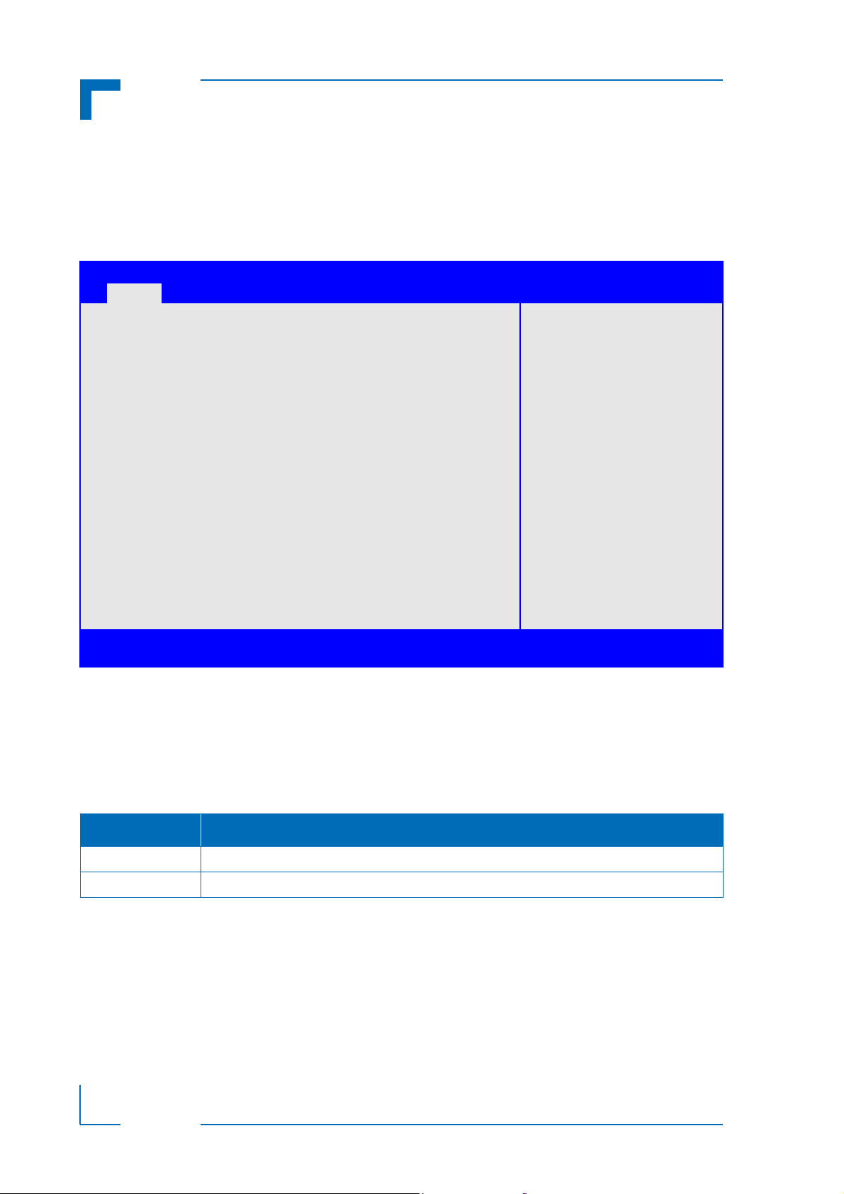
Upon entering the uEFI BIOS Setup program, the Main setup screen is displayed. This screen
lists the main setup sub-screens and provides very basic system information as well as functions for setting the system time and date. In addition, the remaining major setup menus can
be accessed from this screen. This screen can also be selected from any other major setup
screen by using the Main tab.
Aptio Setup Utility - Copyright (C) 2011 American Megatrends, Inc.
Main Boot Security Save & Exit
BIOS Information
BIOS Vendor American Megatrends
Core Version 4.6.5.1
Compliancy UEFI 2.3; PI 1.2
Project Version B3E01 11.00 x64
Build Date and Time 11/05/2012 15:34:19
Memory Information
Memory Frequency 1600 Mhz
Total Memory 4096 MB (DDR3)
Trusted Computing
CPU Configuration
Firmware Update Configuration
USB Configuration
Serial Port Console Redirection
System Language [English]
System Date [Thu 11/22/2012]
System Time [14:15:37]
Access Level Administrator
Version 2.14.1219. Copyright (C) 2011 American Megatrends, Inc.
: Select Screen
: Select Item
Enter: Select
+/-: Change Opt.
F1: General Help
F2: Previous Values
F3 Optimized Defaults
F4: Save & Exit
ESC: Exit
2.1 BIOS Information
This function provides display-only information concerning the uEFI BIOS.
Information about the running uEFI BIOS version is reflected in the display-only function Project
Version (parameter “11.00” indicates Rev. 11).
2.2 Memory Information
This function provides display-only information concerning the system memory.
ID 1053-4014, Rev. 2.0 Page 9
D R A F T — F O R I N T E R N A L U S E O N L Y
Page 16
Main Setup CP3003-SA/CP3003-V uEFI BIOS
2.3 Trusted Computing
This screen provides functions for specifying the TPM configuration settings and TPM displaying status information.
Aptio Setup Utility - Copyright (C) 2011 American Megatrends, Inc.
Main Boot Security Save & Exit
Configuration
TPM Support [Disable]
Current Status Information
NO Security Device Found
: Select Screen
: Select Item
Enter: Select
+/-: Change Opt.
F1: General Help
F2: Previous Values
F3 Optimized Defaults
F4: Save ESC: Exit
Version 2.14.1219. Copyright (C) 2011 American Megatrends, Inc.
2.3.1 Configuration
2.3.1.1 TPM Support (CP3003-SA)
This function is used to provide the Trusted Platform Module (TPM) functionality to the OS.
SETTING DESCRIPTION
Disable Use this setting to disable TPM support.
If this setting is used, TPM is not present for the OS, regardless whether the function TPM
State is enabled or not.
Enable Use this setting to enable TPM support.
Default setting: Disable
2.3.2 Current Status Information
This is a display-only function which provides status information.
D R A F T — F O R I N T E R N A L U S E O N L Y
Page 10 ID 1053-4014, Rev. 2.0
Page 17

CP3003-SA/CP3003-V uEFI BIOS Main Setup
2.4 CPU Configuration
This screen provides information concerning the CPU operating frequencies and the ability to
set the frequency ratio.
Aptio Setup Utility - Copyright (C) 2011 American Megatrends, Inc.
Main Boot Security Save & Exit
CPU Configuration
Inter (R) Core(TM) i7-3517UE CPU @ 1.70GHz
Max CPU Speed 1700 MHz
Min CPU Speed 800 MHz
CPU Speed 1600 MHz
Max Freq Ratio 255
: Select Screen
: Select Item
Enter: Select
+/-: Change Opt.
F1: General Help
F2: Previous Values
F3 Optimized Defaults
F4: Save & Exit
ESC: Exit
Version 2.14.1219. Copyright (C) 2011 American Megatrends, Inc.
2.4.1 CPU Configuration
This is a display-only function indicating general information about the installed CPU.
2.4.2 Max Freq Ratio
This function is used to permit the CPU frequency to be adjusted so as to make a reduction in
power consumption possible when higher performance is not required.
To ensure that the maximum desired frequency is not exceeded, the CPU turbo mode must be
disabled using the uEFI shell command:
“kboardconfig CpuTurbo disabled”
D R A F T — F O R I N T E R N A L U S E O N L Y
ID 1053-4014, Rev. 2.0 Page 11
Page 18
Main Setup CP3003-SA/CP3003-V uEFI BIOS
2.5 Firmware Update Configuration
This screen provides functions for specifying the firmware update configuration settings.
Aptio Setup Utility - Copyright (C) 2011 American Megatrends, Inc.
Main Boot Security Save & Exit
Me FW Image Re-Flash [Disabled]
: Select Screen
: Select Item
Enter: Select
+/-: Change Opt.
F1: General Help
F2: Previous Values
F3 Optimized Defaults
F4: Save & Exit
ESC: Exit
Version 2.14.1219. Copyright (C) 2011 American Megatrends, Inc.
2.5.1 Me FW Image Re-Flash
This function is used to enable or disable Intel® Management Engine (ME) firmware re-flashing.
SETTING DESCRIPTION
Disable Use this setting to disable ME firmware re-flashing.
Enable Use this setting to enable ME firmware re-flashing.
Default setting: Disable
D R A F T — F O R I N T E R N A L U S E O N L Y
Page 12 ID 1053-4014, Rev. 2.0
Page 19

CP3003-SA/CP3003-V uEFI BIOS Main Setup
2.6 USB Configuration
This screen provides information about support for USB devices as well as functions for specifying the USB configuration settings.
Aptio Setup Utility - Copyright (C) 2011 American Megatrends, Inc.
Main Boot Security Save & Exit
USB Configuration
USB Devices:
1 Keyboard, 1 Mouse, 4 Hubs
Legacy USB Support [Enabled]
USB3.0 Support [Enabled]
XHCI Hand-Off [Enabled]
EHCI Hand-Off [Disabled]
: Select Screen
USB hardware delays and time-outs:
USB transfer time-out [20 sec]
Device reset time-out: [20 sec]
Device power-up delay: [Auto]
: Select Item
Enter: Select
+/-: Change Opt.
F1: General Help
F2: Previous Values
F3 Optimized Defaults
F4: Save & Exit
ESC: Exit
Version 2.14.1219. Copyright (C) 2011 American Megatrends, Inc.
2.6.1 USB Configuration
2.6.1.1 USB Devices
This is a display-only function providing general information about the USB devices detected.
2.6.1.2 Legacy USB Support
This function is required for booting from USB devices and for operating systems which do not
support USB themselves (mainly DOS and some BootLoaders).
SETTING DESCRIPTION
Disabled Use this setting to disable legacy USB support.
Enabled Use this setting to enable legacy USB support.
Auto Use this setting to enable legacy USB support if there are USB devices present.
Default setting: Enabled
D R A F T — F O R I N T E R N A L U S E O N L Y
ID 1053-4014, Rev. 2.0 Page 13
Page 20
Main Setup CP3003-SA/CP3003-V uEFI BIOS
2.6.1.3 USB3.0 Support
This function is used to enable USB3.0 support.
SETTING DESCRIPTION
Disabled Use this setting to disable USB3.0 support.
Enabled Use this setting to enable USB3.0 support.
Default setting: Enabled
2.6.1.4 XHCI Hand-Off
This function is used to enable a workaround for operating systems without XHCI Hand-Off
support. The XHCI ownership change should be claimed by the XHCI driver.
SETTING DESCRIPTION
Disabled Use this setting to disable XHCI Hand-Off support.
Enabled Use this setting to enable XHCI Hand-Off support.
Default setting: Enabled
2.6.1.5 EHCI Hand-Off
This function is used to enable a workaround for operating systems without EHCI Hand-Off
support. The EHCI ownership change should be claimed by the EHCI driver.
SETTING DESCRIPTION
Disabled Use this setting to disable EHCI Hand-Off support.
Enabled Use this setting to enable EHCI Hand-Off support.
Default setting: Disabled
D R A F T — F O R I N T E R N A L U S E O N L Y
Page 14 ID 1053-4014, Rev. 2.0
Page 21

CP3003-SA/CP3003-V uEFI BIOS Main Setup
2.6.2 USB Hardware Delays and Time-outs
2.6.2.1 USB Transfer Timeout
This function selects the timeout in seconds that the USB core will wait for Control, Bulk, and
Interrupt transfers.
SETTING DESCRIPTION
01 sec
05 sec
10 sec
20 sec
Use one of these settings to specify how long the USB core is to wait for Control, Bulk, and
Interrupt transfers.
Default setting: 20 sec
2.6.2.2 Device Reset Timeout
This function selects the timeout in seconds that the POST will wait for a USB mass storage
device to become ready after start unit command.
SETTING DESCRIPTION
10 sec
20 sec
30 sec
40 sec
Use one of these settings to specify how long the POST will wait for a USB mass storage
device to become ready after the start unit command.
Default setting: 20 sec
2.6.2.3 Device Power-up Delay
This function determines the maximum time the device will take before it properly reports itself
to the Host Controller. “Auto” uses a default value: for a Root port it is 100 ms, for a Hub port
the delay is taken from Hub descriptor.
If the “Manual” option is chosen, the device power up delay in seconds field will be enabled to
accept a delay ranging from 1 to 40 seconds.
SETTING DESCRIPTION
Auto Use this setting to specify a default delay time for a Root or Hub port.
(root port = 100ms; hub port = value in hub descriptor)
Manual Use this setting to specify a delay time from 1 to 40 seconds.
(contents of seconds field)
Default setting: Auto
ID 1053-4014, Rev. 2.0 Page 15
D R A F T — F O R I N T E R N A L U S E O N L Y
Page 22
Main Setup CP3003-SA/CP3003-V uEFI BIOS
2.7 Serial Port Console Redirection
This screen provides information about functions for specifying the Serial Port Console Redirection configuration settings. Console redirection can be used to remotely operate system settings and the uEFI console.
Aptio Setup Utility - Copyright (C) 2011 American Megatrends, Inc.
Main Boot Security Save & Exit
COM0
Console Redirection [Disabled]
Console Redirection Settings
COM1
Console Redirection [Disabled]
Console Redirection Settings
Serial Port for Out-of-Band Management/
Windows Emergency Management Services (EMS)
Console Redirection [Disabled]
Console Redirection Settings
: Select Screen
: Select Item
Enter: Select
+/-: Change Opt.
F1: General Help
F2: Previous Values
F3 Optimized Defaults
F4: Save & Exit
ESC: Exit
Version 2.14.1219. Copyright (C) 2011 American Megatrends, Inc.
2.7.1 COM0
The COM0 port (serial port 0) corresponds to the COMA port (RS-232) and is available either
on the front panel of the 8HP CP3003-SA/CP3003-V equipped with a CP3003-HDD extension
module or on the rear I/O.
2.7.1.1 Console Redirection
SETTING DESCRIPTION
Disabled Use this setting to disable console redirection for COMA (RS-232).
Enabled Use this setting to enable console redirection for COMA (RS-232).
Default setting: Disabled
2.7.1.2 Console Redirection Settings
D R A F T — F O R I N T E R N A L U S E O N L Y
For information about this function, refer to Chapter 2.7.2.2 in this manual.
Page 16 ID 1053-4014, Rev. 2.0
Page 23

CP3003-SA/CP3003-V uEFI BIOS Main Setup
2.7.2 COM1
The COM1 port (seria l po rt 1 ) corresponds to th e COMB port (RS-232) and is availab le on the
rear I/O.
2.7.2.1 Console Redirection
SETTING DESCRIPTION
Disabled Use this setting to disable console redirection for COMB (RS-232).
Enabled Use this setting to enable console redirection for COMB (RS-232).
Default setting: Disabled
2.7.2.2 Console Redirection Settings
This screen provides information about functions for specifying the Console Redirection configuration settings for the serial port 0 (COM0) and serial port 1 (COM1). Each serial port can
be independently configured.
Aptio Setup Utility - Copyright (C) 2011 American Megatrends, Inc.
Main Boot Security Save & Exit
COM0
Console Redirection Settings
Terminal Type [ANSI]
Bits per second [115200]
Data Bits [8]
Parity [None]
Sto p B i t s [1 ]
Flow Control [None]
VT-UTF8 Combo Key Support [Enabled]
Recorder Mode [Disabled]
Resolution 100x31 [Enabled]
Legacy OS Redirection Resolution [80x24]
Version 2.14.1219. Copyright (C) 2011 American Megatrends, Inc.
: Select Screen
: Select Item
Enter: Select
+/-: Change Opt.
F1: General Help
F2: Previous Values
F3 Optimized Defaults
F4: Save & Exit
ESC: Exit
ID 1053-4014, Rev. 2.0 Page 17
D R A F T — F O R I N T E R N A L U S E O N L Y
Page 24

Main Setup CP3003-SA/CP3003-V uEFI BIOS
2.7.2.2.1 Terminal Type
SETTING DESCRIPTION
VT100 Use one of these settings to select the terminal type to be emulated.
VT100+
VT-UTF8
ANSI
Default setting: ANSI
2.7.2.2.2 Bits per second
SETTING DESCRIPTION
9600 Use one of these settings to select the baud rate of the serial port.
19200
38400
57600
115200
Default setting: 115200
2.7.2.2.3 Data Bits
SETTING DESCRIPTION
7 Use one of these settings to specify the number of data bits per frame.
8
Default setting: 8
2.7.2.2.4 Parity
SETTING DESCRIPTION
None Use one of these settings to select the parity for the serial port.
Even
Odd
Mark
Space
Default setting: None
2.7.2.2.5 Stop Bits
D R A F T — F O R I N T E R N A L U S E O N L Y
SETTING DESCRIPTION
1 Use one of these settings to specify the number of stop bits for the serial port.
2
Default setting: 1
Page 18 ID 1053-4014, Rev. 2.0
Page 25

CP3003-SA/CP3003-V uEFI BIOS Main Setup
2.7.2.2.6 Flow Control
SETTING DESCRIPTION
None Use one of these settings to specify the type of flow control to be used for this serial port.
Hardware RTS/CTS
Default setting: None
2.7.2.2.7 VT-UTF8 Combo Key Support
Use this function to enable or disable VT -UTF8 Combination Key Support for ANSI/ VT100 terminals.
SETTING DESCRIPTION
Disabled Use this setting the disable combination key support.
Enabled Use this setting the enable combination key support.
Default setting: Enabled
2.7.2.2.8 Recorder Mode
Use this function to specify whether display formatting characters are to be transmitted along
with data or if only data is to be transmitted.
SETTING DESCRIPTION
Disabled Use this setting to specify normal terminal operation.
Enabled Use this setting to specify that only text will be sent. Use this to capture terminal data.
Default setting: Disabled
2.7.2.2.9 Resolution 100x31
SETTING DESCRIPTION
Disabled Use this setting the disable extended terminal resolution.
Enabled Use this setting the enable extended terminal resolution.
Default setting: Enabled
2.7.2.2.10 Legacy OS Redirection
SETTING DESCRIPTION
80x24 Use one of these settings to select the number of rows and columns for legacy OS redirec80x25
Default setting: 80x24
ID 1053-4014, Rev. 2.0 Page 19
tion.
D R A F T — F O R I N T E R N A L U S E O N L Y
Page 26

Main Setup CP3003-SA/CP3003-V uEFI BIOS
2.7.3 Serial Port for Out-of-Band Management/Windows Emergency Management Services (EMS)
The following functions control the presence and content of the ACPI serial port redirectio n t able (SPCR). This table is mainly used by the Windows server variants to provide Windows
Emergency Management Services (EMS). This functionality is totally independent from serial
redirection of other console output.
2.7.3.1 Console Redirection
SETTING DESCRIPTION
Disabled Use this setting to prevent the system from adding the SPCR table to the ACPI tables.
Enabled Use this setting to add the SPCR table to the ACPI tables. The OS can further use the infor-
mation provided for serial redirection services.
Default setting: Disabled
2.7.3.2 Console Redirection Settings
This screen provides information about functions for specifying the Console Redirection configuration settings for the Out-of-Band Management / Windows Emergency Management Services (EMS).
Aptio Setup Utility - Copyright (C) 2011 American Megatrends, Inc.
Main Boot Security Save & Exit
Serial Port for Out-of-Band Management
Console Redirection Settings
Out-of-Band Mgmt Port COM0
Terminal Type [VT-UTF8]
Bits per second [115200]
Flow Control [None]
Data Bits 8
Parity None
Stop Bits 1
: Select Screen
: Select Item
Enter: Select
+/-: Change Opt.
F1: General Help
F2: Previous Values
F3 Optimized Defaults
F4: Save & Exit
ESC: Exit
Version 2.14.1219. Copyright (C) 2011 American Megatrends, Inc.
D R A F T — F O R I N T E R N A L U S E O N L Y
Page 20 ID 1053-4014, Rev. 2.0
Page 27

CP3003-SA/CP3003-V uEFI BIOS Main Setup
2.7.3.2.1 Out-of-Band Mgmt Port
This function is used to select the serial port intended for use with Out-of-Band Management.
Note: This function is available only when the respective serial port is enabled.
SETTING DESCRIPTION
COM0 Use this setting to specify that the serial port 0 is to be used with Out-of-Band Management
COM1 Use this setting to specify that the serial port 1 is to be used with Out-of-Band Management
Default setting: COM0
2.7.3.2.2 Terminal Type
SETTING DESCRIPTION
VT100 Use one of these settings to select the terminal type to be emulated.
VT100+
VT-UTF8
ANSI
Default setting: VT-UTF8
2.7.3.2.3 Bits per second
SETTING DESCRIPTION
9600 Use one of these settings to select the baud rate of the serial port.
19200
57600
115200
Default setting: 115200
2.7.3.2.4 Flow Control
SETTING DESCRIPTION
None Use one of these settings to specify the type of flow control to be used for this serial port.
Hardware RTS/CTS
Software Xon/Xoff
Default setting: None
2.7.3.2.5 Data Bits
This is a display-only function providing information about the frame width for the Out-of-Band
Management.
ID 1053-4014, Rev. 2.0 Page 21
D R A F T — F O R I N T E R N A L U S E O N L Y
Page 28

Main Setup CP3003-SA/CP3003-V uEFI BIOS
2.7.3.2.6 Parity
This is a display-only function providing information about the parity for Out-of-Band Management.
2.7.3.2.7 Stop Bits
This is a display-only function providing information about the number of stop bits for Out-ofBand Management.
2.8 System Language
SETTING DESCRIPTION
English Use this function to select the system language. Currently, only English is supported.
2.9 System Date
SETTING DESCRIPTION
<WD MM/DD/YYYY> Use this function to change the system date.
Select System Date using the Up and Down <Arrow> keys. Enter the new values through
the keyboard or press +/- to increment/decrement values. Use “Tab” to switch between
date elements.
2.10 System Time
SETTING DESCRIPTION
<HH:MM:SS> Use this function to change the system time.
Select System Time using the Up and Down <Arrow> keys. Enter the new values through
the keyboard or press +/- to increment/decrement values. Use “Tab” to switch between time
elements.
Note: The time is in 24-hour format. For example, 5:30 A.M. appears as 05:30:00, and
5:30 P.M. as 17:30:00.
2.11 Access Level
This function provides display-only information concerning the uEFI BIOS Setup accessibility
for the current Setup session. The access level is either “Administrator” or “User”.
D R A F T — F O R I N T E R N A L U S E O N L Y
Page 22 ID 1053-4014, Rev. 2.0
Page 29

CP3003-SA/CP3003-V uEFI BIOS Boot Setup
Chapter 1
3
Boot Setup
ID 1053-4014, Rev. 2.0 Page 23
D R A F T — F O R I N T E R N A L U S E O N L Y
Page 30

Boot Setup CP3003-SA/CP3003-V uEFI BIOS
This page has been intentionally left blank.
D R A F T — F O R I N T E R N A L U S E O N L Y
Page 24 ID 1053-4014, Rev. 2.0
Page 31

CP3003-SA/CP3003-V uEFI BIOS Boot Setup
3. Boot Setup
Select the Boot tab to enter the Boot Setup screen. This screen lists the sub-screens for boot
configuration and boot device priority.
Aptio Setup Utility - Copyright (C) 2011 American Megatrends, Inc.
Main Boot Security Save & Exit
Boot Configuration
Setup Prompt Timeout 1
Bootup NumLock State [On]
Quiet Boot [Disabled]
Fast Boot [Disabled]
CSM16 Module Version 07.68
GateA20 Active [Upon Request]
Option ROM Messages [Force BIOS]
Interrupt 19 Capture [Enabled]
CSM Support [Enabled]
Boot Option Priorities
Boot Option #1 [UEFI: Built-in EFI...]
Boot Option #2 [P0: TOSHIBA MK1676...]
Hard Drive BBS Priorities
Version 2.14.1219. Copyright (C) 2011 American Megatrends, Inc.
: Select Screen
: Select Item
Enter: Select
+/-: Change Opt.
F1: General Help
F2: Previous Values
F3 Optimized Defaults
F4: Save & Exit
ESC: Exit
3.1 Boot Configuration
3.1.1 Setup Prompt Timeout
This integer function is used to set an additional time the POST should wait for the operator to
press the key to enter SETUP. The time is entered in seconds.
SETTING DESCRIPTION
1
.
.
.
65535
Use one of these settings to specify the setup prompt timeout.
Default setting: 1
3.1.2 Bootup NumLock State
This function is used to set the state of the keyboard’s numlock function after POST.
SETTING DESCRIPTION
On Use this setting to switch on the keyboard’s numlock function after POST.
Off Use this setting to switch off the keyboard’s numlock function after POST.
Default setting: On
ID 1053-4014, Rev. 2.0 Page 25
D R A F T — F O R I N T E R N A L U S E O N L Y
Page 32

Boot Setup CP3003-SA/CP3003-V uEFI BIOS
3.1.3 Quiet Boot
This function is used to display either POST output messages or a splash screen during boot-up.
SETTING DESCRIPTION
Disabled Use this setting to display POST output messages during boot-up.
Enabled Use this setting to display a splash screen during boot-up.
Default setting: Disabled
3.1.4 Fast Boot
This function is used to enable or disable boot with initialization of a minimal set of devices required to launch active boot option..
SETTING DESCRIPTION
Disabled Use this setting to disable fast boot.
Enabled Use this setting to enable fast boot.
Default setting: Disabled
3.1.5 CSM16 Module Version
This function provides display-only information concerning the CSM Module and is intended for
internal use only.
3.1.6 GateA20 Active
This function is used to enable or disable GateA20.
SETTING DESCRIPTION
Upon Request Use this setting to disable GateA20 in the uEFI BIOS.
Always Use this setting to prevent the system from disabling GateA20.
Default setting: Upon Request
3.1.7 Option ROM Messages
This function is used to control the messages of the loaded PCI option ROMs.
SETTING DESCRIPTION
Force BIOS Use this setting to force to a BIOS-compatible output. This will show the option ROM mes-
sages.
Keep Current Use this setting to keep the current video mode. This will suppress option ROM messages.
Option ROMs requiring interactive inputs may not work properly in this mode.
D R A F T — F O R I N T E R N A L U S E O N L Y
Default setting: Force BIOS
Page 26 ID 1053-4014, Rev. 2.0
Page 33

CP3003-SA/CP3003-V uEFI BIOS Boot Setup
3.1.8 Interrupt 19 Capture
This function is used to specify if legacy PCI option ROMs are allowed to capture software interrupt 19h.
SETTING DESCRIPTION
Disabled Use this setting to prevent legacy PCI option ROMs from capturing software interrupt 19h.
Enabled Use this setting to allow legacy PCI option ROMs to capture software interrupt 19h.
Default setting: Enabled
3.1.9 CSM Support
This function is used to enable or disable CSM support.
SETTING DESCRIPTION
Disabled Use this setting to disable CSM support.
Enabled Use this setting to enable CSM support.
Default setting: Enabled
3.2 Boot Option Priorities
3.2.1 Boot Option #1..2
These functions are used to form the boot order and are dynamically generated. They represent either a legacy BBS (BIOS Boot Specification) class of devices or a native EFI boot entry.
Press Return on each option to select the BBS class / EFI boot entry desired.
3.2.2 Hard Drive BBS Priorities
This function leads to a sub-menu that allows configuring the boot order for a specific device
class. These options are only visible if at least one device for this class is present. These functions are dynamically generated.
ID 1053-4014, Rev. 2.0 Page 27
D R A F T — F O R I N T E R N A L U S E O N L Y
Page 34

Boot Setup CP3003-SA/CP3003-V uEFI BIOS
This page has been intentionally left blank.
D R A F T — F O R I N T E R N A L U S E O N L Y
Page 28 ID 1053-4014, Rev. 2.0
Page 35

CP3003-SA/CP3003-V uEFI BIOS Security Setup
Chapter 1
4
Security Setup
ID 1053-4014, Rev. 2.0 Page 29
Page 36

Security Setup CP3003-SA/CP3003-V uEFI BIOS
This page has been intentionally left blank.
Page 30 ID 1053-4014, Rev. 2.0
Page 37

CP3003-SA/CP3003-V uEFI BIOS Security Setup
4. Security Setup
Select the Security tab to enter the Security Setup screen. This screen provides information
about the passwords and functions for specifying the security settings.
Aptio Setup Utility - Copyright (C) 2011 American Megatrends, Inc.
Main Boot Security Save & Exit
Password Description
If ONLY the Administrator’s password is set,
then this only limits access to Setup and is
only asked for when entering Setup.
If ONLY the User’s password is set, then this
is a power on password and must be entered to
boot or enter Setup. In Setup the User will
have Administrator rights.
The password length must be
in the following range:
Minimum length 3
Maximum length 20
Administrator Password
User Password
HDD Security Configuration
P0:TOSHIBA MK16
: Select Screen
: Select Item
Enter: Select
+/-: Change Opt.
F1: General Help
F2: Previous Values
F3 Optimized Defaults
F4: Save & Exit
ESC: Exit
Version 2.14.1219. Copyright (C) 2011 American Megatrends, Inc.
The following modes of security are provided:
SETTING DESCRIPTION
No password is
set
Only Administrator
password is set
Only User password is set
Both User and
Administrator
passwords are set
Booting the system as well as entering the Setup is unsecured.
Booting the system is unsecured.
For entering the Setup, the Administrator password is required.
The password is required for booting the system as well as for entering the Setup menu. On
every startup, the user will be asked for the password.
Either the User or the Administrator password is required for booting the system as well as for
entering the Setup menu.
If the User password is entered here, limited access to the Setup is granted. Entering the
Administrator password provides full access to all Setup entries.
Note: The CP3003-SA/CP3003-V provides no factory-set passwords.
ID 1053-4014, Rev. 2.0 Page 31
Page 38

Security Setup CP3003-SA/CP3003-V uEFI BIOS
4.1 Administrator Password
This function is used to set, change or delete the Administrator password. If there is already a
password installed, the system asks for this first . To clear a password, simply enter nothing and
acknowledge by pressing Return. To set a p assword, enter it twice and acknowle dge by pressing Return.
Note: The password is case sensitive.
4.2 User Password
This function is used to set, change or delete the User p assword. If there is already a p assword
installed, the system asks for this first. To clear a p assword, simply enter nothing and acknowledge by pressing Return. To set a password, enter it twice and acknowledge by pressing Return.
Note: The password is case sensitive.
4.3 HDD Security Configuration
Allows access to set, modify and clear the harddisk User password. The harddisk User password must be set to enable harddisk security.
Note:
Note: The harddisk User password is case sensitive.
This function is only available if a HDD/SSD is detected w hich supports this functio n.
4.4 Remember the Password
It is highly recommended to keep a record of all passwords in a safe place. Forgotten passwords may lead to being completely locked out of the system.
If the system cannot be booted because neither the uEFI BIOS User password nor the Administrator password are known, refer to the CP3003-SA/CP3003-V User Guide, Chapter 4.1, for
information about clearing the uEFI BIOS settings, or contact Kontron for further assistance.
Note: The harddisk User password cannot be cleared using the above method.
Page 32 ID 1053-4014, Rev. 2.0
Page 39

CP3003-SA/CP3003-V uEFI BIOS Save & Exit
Chapter 1
5
Save & Exit
ID 1053-4014, Rev. 2.0 Page 33
D R A F T — F O R I N T E R N A L U S E O N L Y
Page 40

Save & Exit CP3003-SA/CP3003-V uEFI BIOS
This page has been intentionally left blank.
D R A F T — F O R I N T E R N A L U S E O N L Y
Page 34 ID 1053-4014, Rev. 2.0
Page 41

CP3003-SA/CP3003-V uEFI BIOS Save & Exit
5. Save & Exit
Select the Save & Exit tab to enter the Save & Exit menu screen. This screen provides functions
for handling changes made to the uEFI BIOS settings and the exiting of the Setup program.
Aptio Setup Utility - Copyright (C) 2011 American Megatrends, Inc.
Main Boot Security Save & Exit
Save Changes and Exit
Discard Changes and Exit
Save Changes and Reset
Discard Changes and Reset
Save Options
Save Changes
Discard Changes
Restore Defaults
Save as User Defaults
Restore User Defaults
Boot Override
UEFI: Built-in EFI Shell
P0: TOSHIBA MK1676GSX
Version 2.14.1219. Copyright (C) 2011 American Megatrends, Inc.
: Select Screen
: Select Item
Enter: Select
+/-: Change Opt.
F1: General Help
F2: Previous Values
F3 Optimized Defaults
F4: Save & Exit
ESC: Exit
5.1 Save Changes and Exit
This function is used to save all changes made within the Setup to flash. This function continues the boot process as long as no option was altered that requires a reboot.
Note: The Setup will ask for confirmation prior to executing this command.
5.2 Discard Changes and Exit
This function is used to discard all changes made within the Setup. This function continues the
boot process.
Note: The Setup will ask for confirmation prior to executing this command.
5.3 Save Changes and Reset
This function is used to save all changes made within the Setup to flash. This function performs
a reboot afterwards.
Note: The Setup will ask for confirmation prior to executing this command.
ID 1053-4014, Rev. 2.0 Page 35
D R A F T — F O R I N T E R N A L U S E O N L Y
Page 42

Save & Exit CP3003-SA/CP3003-V uEFI BIOS
5.4 Discard Changes and Reset
This function is used to discard all changes made within the Setup. This function performs a
reboot afterwards.
Note: The Setup will ask for confirmation prior to executing this command.
5.5 Save Changes (Save Options)
This function is used to save all changes made within the Setup to flash. This function returns
to Setup.
Note: The Setup will ask for confirmation prior to executing this command.
5.6 Discard Changes (Save Options)
This function is used to discard all changes made within the Setup. This function returns to Setup.
Note: The Setup will ask for confirmation prior to executing this command.
5.7 Restore Defaults (Save Options)
This function is used to restore all tokens to factory default.
Note: The Setup will ask for confirmation prior to executing this command.
5.8 Save as User Defaults (Save Options)
This function is used to save all current settings as user default. The current setup state can
later be restored using Restore User Defaults.
Note: The Setup will ask for confirmation prior to executing this command.
5.9 Restore User Defaults (Save Options)
This function is used to restore all tokens to settings previously stored by Save as User Defaults.
Note: The Setup will ask for confirmation prior to executing this command.
5.10 Boot Override
This group of functions includes a list of tokens, each of them corresponding to one device within the boot order. Select a drive to immediately boot that device regardless of the current boot
order. If booting to EFI Shell this way, an exit from the shell returns to Setup.
D R A F T — F O R I N T E R N A L U S E O N L Y
Page 36 ID 1053-4014, Rev. 2.0
Page 43

CP3003-SA/CP3003-V uEFI BIOS The uEFI Shell
Chapter 1
6
The uEFI Shell
ID 1053-4014, Rev. 2.0 Page 37
D R A F T — F O R I N T E R N A L U S E O N L Y
Page 44

The uEFI Shell CP3003-SA/CP3003-V uEFI BIOS
This page has been intentionally left blank.
D R A F T — F O R I N T E R N A L U S E O N L Y
Page 38 ID 1053-4014, Rev. 2.0
Page 45

CP3003-SA/CP3003-V uEFI BIOS The uEFI Shell
6. The uEFI Shell
The Kontron uEFI BIOS features a built-in and enhanced version of the uEFI Shell. For a detailed description of the available standard shell scripting refer to the EFI Shell User’s Guide.
For a detailed description of the available standard shell commands, refer to the Shell Command Manual 1.0. Both documents can be downloaded from the EFI and Framework Open
Source Community homepage (https://efi-shell.tianocore.org) un der the “Documents and Files”
section.
Please note that not all shell commands described in the Shell Command Manual 1.0 are provided by the Kontron uEFI BIOS.
6.1 Introduction, Basic Operation
The uEFI Shell forms an entry into the uEFI boot order and is the first boot option by default. It
is simply started by putting the uEFI Shell first in boot and running the board as usual.
6.1.1 Shell Startup
If the shell is executed, it displays its signon message followed by a list of detected devices.
The output produced by the device mapping table can vary depending on the board’ s con figuration.
EFI Shell version 2.31 [4.651]
Current running mode 1.1.2
Device mapping table
fs0 :Removable HardDisk - Alias hd33b0b0b blk0
Acpi(PNP0A03,0)/Pci(1D|7)/Usb(1, 0)/Usb(1, 0)/HD(Part1,Sig17731773)
fs1 :Removable BlockDevice - Alias f33b0c0 blk1
Acpi(PNP0A03,0)/Pci(1D|7)/Usb(1, 0)/Usb(2, 0)
blk0 :Removable HardDisk - Alias hd33b0b0b fs0
Acpi(PNP0A03,0)/Pci(1D|7)/Usb(1, 0)/Usb(1, 0)/HD(Part1,Sig17731773)
blk1 :Removable BlockDevice - Alias f33b0c0 fs1
Acpi(PNP0A03,0)/Pci(1D|7)/Usb(1, 0)/Usb(2, 0)
blk2 :HardDisk - Alias (null)
Acpi(PNP0A03,0)/Pci(1F|2)/Ata(Primary,Master)/HD(Part1,SigC811D18D)
blk3 :BlockDevice - Alias (null)
Acpi(PNP0A03,0)/Pci(1F|2)/Ata(Primary,Master)
blk4 :Removable BlockDevice - Alias (null)
Acpi(PNP0A03,0)/Pci(1D|7)/Usb(1, 0)/Usb(1, 0)
Press the ESC key within 5 seconds to skip sta rtup.nsh, and any other key to
continue.
If the ESC key is pressed before the 5-second timeout has elap sed, the shell prompt is shown:
Shell>
ID 1053-4014, Rev. 2.0 Page 39
D R A F T — F O R I N T E R N A L U S E O N L Y
Page 46

The uEFI Shell CP3003-SA/CP3003-V uEFI BIOS
6.2 Kontron-Specific uEFI Shell Commands
The Kontron uEFI implementation provides the following additional commands related to the
specific HW features of the Kontron system:
• kBiosRevision
• kboardconfig
• kboardinfo
• kboot
• kbootnsh
• kclearnvram
• kflash
• kmkramdisk
• kpassword
• kresetconfig
• kSettings
• kwdt
The following tables provide information concerning these Kontron-specific commands. Where
“RESPONSE” information is provided in “USAGE”, the value indicated in brackets is the currently selected setting. Where “SETTINGS” information is provided, the value indicated in
brackets is the current setting.
D R A F T — F O R I N T E R N A L U S E O N L Y
Page 40 ID 1053-4014, Rev. 2.0
Page 47

CP3003-SA/CP3003-V uEFI BIOS The uEFI Shell
6.2.1 kBiosRevision uEFI Shell Command kBiosRevision
FUNCTION: Get uEFI BIOS revision
SYNTAX: kbiosrevision [-?] [[-lt] [-eq] [-gt] <number>]
where:
-? Show help
-lt Check if current uEFI BIOS revision is less than
<number>
-eq Check if current uEFI BIOS revision is equal to
<number>
-gt Check if current uEFI BIOS revision is greater than
<number>
<number> (uEFI BIOS) revision number
DESCRIPTION: The kBiosRevision command is used to display the current uEFI BIOS
revision.
In scripting environments it can be used to perform checks against a
uEFI BIOS revision number provided in the script.
USAGE: Display current uEFI BIOS revision:
COMMAND / RESPONSE EXAMPLE:
Shell> kbiosrevision
BIOS revision: 11
Check if current uEFI BIOS revision is equal to R11:
(used within uEFI shell script)
kbiosrevsion -eq 11
if not %lasterror% == 0 then
echo "NOT R11 , need to update"
goto _update
else
"EFI R11 found"
endif
....
....
ID 1053-4014, Rev. 2.0 Page 41
D R A F T — F O R I N T E R N A L U S E O N L Y
Page 48

The uEFI Shell CP3003-SA/CP3003-V uEFI BIOS
6.2.2 kboardconfig uEFI Shell Command kboardconfig
FUNCTION: Configure the non-volatile board settings
SYNTAX:
kboardconfig [-?][-b][-nc] <option> <parameter>
where:
? Used to show HELP
-b Used to invoke page break in the display output
-nc Used to disable color
<option> Used to select option
<parameter> Used to specify parameter for option selected
The command notation above indicates only the possible modifiers and
not the command’s syntax logic.
There are eight defined variations of this command:
kboardconfig lists options and their current status
kboardconfig -b lists options, their current status, and in-
vokes page breaks in the display output
kboardconfig -nc lists options, their current status, and dis-
ables color in the display output
kboardconfig -? provides HELP information
kboardconfig -? -b provides HELP information and invokes
page breaks in the display output
kboardconfig <option> provides HELP for option specified and the
current status of the option
kboardconfig <option> -nc provides HELP for option specified, the
current status of the option, and disables
color in display output
kboardconfig <option> <parameter>
sets the <parameter> to be used with the
<option> specified
DESCRIPTION: The kboardconfig command is used to configure non-volatile board
settings. For information on default settings, refer to Chapter 5.7,
Restore Defaults, and Chapter 6.2.6, kclearnvram uEFI Shell
Command.
D R A F T — F O R I N T E R N A L U S E O N L Y
Page 42 ID 1053-4014, Rev. 2.0
Page 49

CP3003-SA/CP3003-V uEFI BIOS The uEFI Shell
kboardconfig (continued)
USAGE: Command: kboardconfig
Shows all options and their current parameter setting.
COMMAND / RESPONSE EXAMPLE:
Shell> kboardconfig
StorageOprom -> enabled
PrimaryDisplay -> auto
Vga -> front
VgaInterrupt -> disabled
SataMode -> ahci
Sata0Speed -> noLimit
Sata1Speed -> noLimit
Sata2Speed -> noLimit
Sata3Speed -> noLimit
Sata4Speed -> noLimit
Sata5Speed -> noLimit
Sata2Hotplug -> disabled
Sata3Hotplug -> disabled
WrProtSata -> disabled
WrProtEeprom -> disabled
WrProtSpi -> disabled
IntelVT -> enabled
IntelHT -> enabled
SpeedStep -> enabled
CpuTurbo -> enabled
C3State -> disabled
C6State -> disabled
C7State -> enabled
PciCfgDelay -> disabled
GbeA -> front
GbeB -> front
ComA -> rear
Pxe -> disabled
Tdp -> disabled
ID 1053-4014, Rev. 2.0 Page 43
D R A F T — F O R I N T E R N A L U S E O N L Y
Page 50

The uEFI Shell CP3003-SA/CP3003-V uEFI BIOS
kboardconfig (continued)
USAGE:
(continued)
Command: kboardconfig -?
Shows HELP information for the kboardconfig command.
COMMAND / RESPONSE EXAMPLE:
Shell> kboardconfig -?
Control nonvolatile board settings
Example: kboardconfig <option> <parameter>
Show all options and their current status:
kboardconfig
Show help:
kboardconfig -?
Show all options and their current status with page
break:
kboardconfig -b
Show all options and their current status without
color:
kboardconfig -nc
Show help and status for a single option:
kboardconfig <option>
kboardconfig -nc <option>
Change parameter for an option:
kboardconfig <option> <parameter>
Command: kboardconfig <option>
Show help and status for a single option:
COMMAND / RESPONSE EXAMPLE:
Shell> kboardconfig Pxe
Pxe:
PXE boot device
Available parameters: [disabled], all, gbeA, gbeB,
gbeC
In this case “disabled” is the current setting.
D R A F T — F O R I N T E R N A L U S E O N L Y
Page 44 ID 1053-4014, Rev. 2.0
Page 51

CP3003-SA/CP3003-V uEFI BIOS The uEFI Shell
kboardconfig (continued)
USAGE:
(continued)
OPTIONS: The listing below provides an overview of the possible options and a
Command: kboardconfig <option> <parameter>
Set option “Pxe” to parameter “all”:
COMMAND / RESPONSE EXAMPLE:
Shell> kboardconfig Pxe all
The response for “kboardconfig” with <option> and <parameter> is the
display of a status line indicating the performance status of the command
and one or more lines providing further information related to the
command performance.
short description of their functionality.
To view all of the possible parameters for a given option, use the
command “kboardconfig <option>”.
OPTION DESCRIPTION
StorageOprom Used to launch the Storage PCI OPROM
When disabled it includes the onboard RAID option
ROM
PrimaryDisplay Used to select the primary display device
auto: Automatically detect primary display device
igfx: Use internal graphics, if enabled
peg: Try to use video on the PCIe graphics port, if
present (CP3003-SA only)
pci: Try to use video on the PCI(e) bus first
Vga Used to select the VGA port configuration
VgaInterrupt Used to enable the VGA interrupt generation
SataMode Used to select the operational configuration for the
SATA controller
ide: SATA ports operate as two IDE controllers
ahci: SATA ports operate as one 6-port AHCI
controller
raid: SATA ports form a RAID device
Note: For this command to take effect, the system
must be re-booted. During the bootup, it is
possible to select a menu to specify the
desired RAID configuration. Entry to this menu
is achieved by pressing “Ctrl + I” when
requested during the bootup.
D R A F T — F O R I N T E R N A L U S E O N L Y
ID 1053-4014, Rev. 2.0 Page 45
Page 52

The uEFI Shell CP3003-SA/CP3003-V uEFI BIOS
kboardconfig (continued)
OPTIONS:
(continued)
Sata0Speed Indicates maximum speed supported by SATA port 0
(SATA cable connector J3 on the CP3003-SA/
CP3003-V main board)
Available parameters for SATA0Speed and
SATA1Speed:
noLimit,
gen1 (SATA 1.5 Gb/s),
gen2 (SATA 3.0 Gb/s),
gen3 (SATA 6.0 Gb/s)
Sata1Speed Indicates maximum speed supported by SATA port 1
(SATA connector J6 on the CP3003-HDD module)
For available parameters, refer to SATA0Speed.
Sata2Speed Indicates maximum speed supported by SATA port 2
(SATA connector J6 on the CP-RIO3-04 module)
Available parameters for SATA2Speed to
SATA5Speed:
noLimit,
gen1 (SATA 1.5 Gb/s),
gen2 (SATA 3.0 Gb/s)
Sata3Speed Indicates maximum speed supported by SATA port 3
(SATA connector J5 on the CP-RIO3-04 module)
For available parameters, refer to SATA2Speed.
Sata4Speed Indicates maximum speed supported by SATA port 4
(CFast connector J3 on the 8 HP CP3003-SA/
CP3003-V with CP3003-HDD module / High-speed I/
O extension connector J4 for 12 HP CP3003-SA/
CP3003-V expansion)
For available parameters, refer to SATA2Speed.
Sata5Speed Indicates maximum speed supported by SATA port 5
(SATA connector J12 on the CP3003-SA/CP3003-V
main board for connection to the SATA Flash module)
For available parameters, refer to SATA2Speed.
Sata2Hotplug: Enable hotplug for SATA port 2
(SATA connector J6 on the CP-RIO3-04 module)
Sata3Hotplug: Enable hotplug for SATA port 3
(SATA connector J5 on the CP-RIO3-04 module)
D R A F T — F O R I N T E R N A L U S E O N L Y
Page 46 ID 1053-4014, Rev. 2.0
Page 53

CP3003-SA/CP3003-V uEFI BIOS The uEFI Shell
kboardconfig (continued)
OPTIONS:
(continued)
WrProtSata: Used to select onboard SATA flash write protection
If enabled, the onboard SATA flash is write-protected
after POST. OS needs to be prepared to work with
write-protected flash. For further information, refer to
the operating system’s documentation.
Note: Please contact Kontron before using this
function.
WrProtEeprom: Used to select onboard system EEPROM write
protection
If enabled, the system EEPROM is write-protected
after POST.
WrProtSpi Used to select onboard SPI boot flash write protection
If enabled, both of the onboard SPI boot flashes are
write-protected after POST.
IntelVT Used to enable Intel® VT-x Virtualization Technology
IntelHT Used to enable Intel® Hyper-Threading Technology
SpeedStep Used to enable Intel® SpeedStep®
CpuTurbo Used to enable CPU turbo mode
C3State Used to enable CPU C3-State report to OS
C6State Used to enable CPU C6-State report to OS
C7State Used to enable CPU C7-State report to OS
PciCfgDelay Used to set a delay for PCI config cycles
D R A F T — F O R I N T E R N A L U S E O N L Y
ID 1053-4014, Rev. 2.0 Page 47
Page 54

The uEFI Shell CP3003-SA/CP3003-V uEFI BIOS
kboardconfig (continued)
OPTIONS:
(continued)
GbeA Used to select the routing of the GbeA port
GbeB Used to select the routing of the GbeB port
ComA Used to select the routing of the serial port 0
Note: This option is only valid for CP3003-SA/
CP3003-V rear /O versions.
Pxe Used to select a PXE boot device
gbeA and gbeB: Ethernet ports available on the
front panel of the 4 HP CP3003-SA/CP3003-V
via the J7A/B dual Gigabit Ethernet connector.
These ports are switchable to rear I/O.
gbeC: Ethernet port available on the front panel
of the 8 HP CP3003-SA/CP3003-V with a
CP3003-HDD extension module via the Gigabit
Ethernet connector J5.
Tdp Used to select a lower operating TDP level by
preserving maximum possible performance.
D R A F T — F O R I N T E R N A L U S E O N L Y
Page 48 ID 1053-4014, Rev. 2.0
Page 55

CP3003-SA/CP3003-V uEFI BIOS The uEFI Shell
6.2.3 kboardinfo uEFI Shell Command kboardinfo
FUNCTION: Show board identification data
SYNTAX: kboardinfo
DESCRIPTION: The kboardinfo command shows a summary of board-specific
identification data. It is especially useful for support queries because it
contains this data in a concentrated form.
USAGE: Show board identification data
COMMAND / RESPONSE EXAMPLE:
Shell> kboardinfo
KOMaOEMF rev.: 4
Board ID: 0xB3E0
Hardware rev.: 0x0
Logic rev.: 0x02
Boot flash: Standard SPI Boot flash
In system slot: Yes
Geographic address: 1
Material number: 1234-5678
Hardware index: 10
Serial number: 1234567001
EFI article name: SK-EFI-B3E01
EFI material number: 1051-8483
EFI index: 11, standard
EFI build time: 15:34:19
EFI build date: 11/05/2012
CPU rev.: 0x9
Chipset rev.: 0x4
Microcode: 0x15
CPU ID: 0x306A9
CPU Branding: Intel(R) Core(TM) i7-3517UE CPU
@ 1.70 GHz
ME firmware rev.: 8.0.13.1502
VBIOS rev.: 2137
ID 1053-4014, Rev. 2.0 Page 49
D R A F T — F O R I N T E R N A L U S E O N L Y
Page 56

The uEFI Shell CP3003-SA/CP3003-V uEFI BIOS
kboardinfo (continued)
USAGE:
(continued)
KOMaOEMF rev.: Revision of KOMaOEMF protocol
Board ID: Kontron board identification value
Hardware rev.: Hardware revision of this board
Logic rev.: Logic revision of this board
Boot flash: Current boot flash: either “Standard SPI boot
flash” or “Recovery SPI boot flash”
In system slot: Indicates that the board is installed in the
system slot
Geographic Address: Geographic address of the cPCI backplane
slot the board is currently plugged into
Material number: Kontron hardware reference number
Hardware index: Kontron hardware index
Serial number: This board’s unique serial number
EFI article name: Kontron uEFI reference name
EFI material number: Kontron uEFI reference number
EFI index: Version of this uEFI BIOS
EFI build time: Build time of this uEFI BIOS
EFI build date: Build date of this uEFI BIOS
CPU rev.: Chip revision of the CPU
Chipset rev.: Chip revision of the chipset
Microcode: Currently loaded microcode
CPU ID: CPUID
CPU Branding: CPU identification string
ME firmware rev: Revision of the Intel® ME Firmware
VBIOS rev: Revision of the Intel® Video BIOS
D R A F T — F O R I N T E R N A L U S E O N L Y
Page 50 ID 1053-4014, Rev. 2.0
Page 57

CP3003-SA/CP3003-V uEFI BIOS The uEFI Shell
6.2.4 kboot uEFI Shell Command kboot
FUNCTION:
SYNTAX:
DESCRIPTION:
Boot a legacy OS
Not to be used for uEFI BootLoaders!
kboot [-?] [-d] [-p <path>] [-n <name>] [-t <type>]
where:
-? Show online help
-d Boot default order
-p <path> Specify the path to the device to boot from
-n <name> Specify the device name to boot from
-t <type> Specify the device type to boot from
Available types are:
floppy
harddrive
cdrom
network
usb-floppy
usb-harddrive
usb-cdrom
The kboot command boots a legacy OS. If the requested device is not
present, boot returns to shell. The kboot command cannot boot native
uEFI-aware operating systems. But since these are bootable from shell
by calling their bootloader, this is not necessary either. If a requested
device is present but not bootable, uEFI continues to boot with the next
bootable device in the boot order.
USAGE:
Show all connected devices:
COMMAND / RESPONSE EXAMPLE:
Shell> kboot
_____BBS_TABLE_____
00001 usb-harddrive "SanDisk Extreme 0001"
Device path: PciRoot(0x0)/Pci(0x1d,0x0)/
USB(0x1,0x0)/USB(0x3,0x0)
00003 network "IBA GE Slot 0100 v1372"
00002 network "IBA GE Slot 0200 v1372"
00004 network "IBA GE Slot 0500 v1372"
00000 harddrive "P1: TOSHIBA MK1665GSX "
Device path: PciRoot(0x0)/Pci(0x1f,0x2/Sata(0x1,0x0)
D R A F T — F O R I N T E R N A L U S E O N L Y
ID 1053-4014, Rev. 2.0 Page 51
Page 58

The uEFI Shell CP3003-SA/CP3003-V uEFI BIOS
kboot
USAGE:
(continued)
Boot from device containing the string "SanDisk":
Shell> kboot -n SanDisk
Boot from first device found that is of type harddrive:
Shell> kboot -t harddrive
Boot from device using the path to the device:
Shell> kboot -p "PciRoot(0x0)/Pci(0x1f,0x2/Sata(0x1,0x0)"
6.2.5 kbootnsh uEFI Shell Command kbootnsh
FUNCTION: Manage the startup script stored in the flash
SYNTAX: kbootnsh [-?] [-b] [-d] [[-g] [-p] <filename>]
where:
-b Display output page by page
-? Show online help
-g <filename> Store the current boot script to disk. If there is no physical disk drive present, the kmkramdisk command
may be used.
-p <filename> Store the shell script pointed to by filename to flash.
Note: The shell script cannot be larger then 400
bytes.
-d Delete the current startup script from flash.
DESCRIPTION: The kbootnsh command manages the flash-stored startup script. If the
shell is launched by the boot process, it executes a shell script stored in
the flash. If the shell script terminates, the shell will continue the boot
process. However, the shell script can of course contain any other boot
command.
USAGE: Get current startup script to file named boot.nsh
COMMAND / RESPONSE EXAMPLE:
Shell> kbootnsh -g boot.nsh
Store file named boot.nsh to flash:
COMMAND / RESPONSE EXAMPLE:
D R A F T — F O R I N T E R N A L U S E O N L Y
Shell> kbootnsh -p boot.nsh
Delete startup script:
COMMAND / RESPONSE EXAMPLE:
Shell> kbootnsh -d
Page 52 ID 1053-4014, Rev. 2.0
Page 59

CP3003-SA/CP3003-V uEFI BIOS The uEFI Shell
6.2.6 kclearnvram uEFI Shell Command kclearnvram
FUNCTION: Clear the NVRAM to restore the system’s default settings
SYNTAX: kclearnvram [-?] [-q]
where:
-? Show online help
-q Silent mode operation
(for use of this command in shell scripts)
DESCRIPTION: Invoking the kclearnvram command clears the system NVRAM. Since
all uEFI settings are stored inside the NVRAM, the default settings are
loaded afterwards.
When invoked without the “-q” option, this command must be confirmed
by pressing “c”.
If invoked with the “-q” option, no confirmation is requested.
ID 1053-4014, Rev. 2.0 Page 53
D R A F T — F O R I N T E R N A L U S E O N L Y
Page 60

The uEFI Shell CP3003-SA/CP3003-V uEFI BIOS
6.2.7 kflash uEFI Shell Command kflash
FUNCTION:
SYNTAX:
Manage uEFI BIOS update
kflash [-?] [-h] [-q] [-c] [-i]
[[-p] [-v] [-s] [-r] [-f] <file>]
where:
-? Show online help
-h Show this help
-p Program flash
-i Show information string and check CRC
-v Verify flashed image
-s Save current ROM image to file
-c Clone flash content to second flash
-f Force write
-q Silent mode, no user interaction required
(for use of this command in shell scripts)
-r Raw image mode (.bin, .rom)
(expert function, not recommended for standard
usage)
<file> uEFI BIOS binary file
DESCRIPTION:
USAGE: Get help:
D R A F T — F O R I N T E R N A L U S E O N L Y
The kflash command is used to program and verify the flash banks
holding the uEFI BIOS code. uEFI BIOS binary files must be available
from connected mass storage devices, such as USB flash drive or
harddisk.
COMMAND / RESPONSE EXAMPLE:
Shell> kflash -?
Get help:
COMMAND / RESPONSE EXAMPLE:
Shell> kflash -h
Program the uEFI BIOS into the standard SPI boot flash:
COMMAND / RESPONSE EXAMPLE:
Shell> kflash -p BIOS_file.kfl
Note: This function will select and update the standard SPI boot flash
regardless of the DIP switch setting for boot flash selection.
Page 54 ID 1053-4014, Rev. 2.0
Page 61

CP3003-SA/CP3003-V uEFI BIOS The uEFI Shell
kflash (continued)
USAGE:
(continued)
Copy the currently running uEFI BIOS into the inactive SPI boot flash:
COMMAND / RESPONSE EXAMPLE:
Shell> kflash -c
Note: Using this function will overwrite the inactive SPI boot flash.
Failures during the process will make the inactive SPI boot flash
invalid. In such cases, it will be necessary to execute the
function again until the process completes successfully.
6.2.8 kmkramdisk uEFI Shell Command kmkramdisk
FUNCTION: Create RAMdisk drives
SYNTAX: kmkramdisk [-?] [-s <size> <name>]
where:
-? show help
-s <size> <name> create a RAMdisk of given size in Megabytes with
the mount point name <name>
DESCRIPTION: Creates a RAMdisk of variable size. Can be very useful to perform file
operations when no real filesystem is connected to the system.
Note: The RAMdisk loses its mount point name after all drives are
remapped by the map -r command. The RAMdisk will then be
enumerated as any other connected drive and gain a mount
point name like “fs0”. This is not a bug of the kmkramdisk
command but a normal function of the uEFI framework.
USAGE: Create RAMdisk:
COMMAND / RESPONSE EXAMPLE:
rd:\> kmkramdisk -s 5 myramdisk
Device mapping table
myramdisk :BlockDevice - Alias (null)
VenMsg’(93B5F448-127A-4B29-B306 5BE8AAC4826E)
Success - Force file system to mount
rd:\> myramdisk:
myramdisk:\> echo testfile > testfile
myramdisk:\> ls
Directory of: myramdisk:\
05/24/08 04:39a 22 testfile
1 File(s) 22 bytes
0 Dir(s)
D R A F T — F O R I N T E R N A L U S E O N L Y
ID 1053-4014, Rev. 2.0 Page 55
Page 62

The uEFI Shell CP3003-SA/CP3003-V uEFI BIOS
6.2.9 kpassword uEFI Shell Command kpassword
FUNCTION:
SYNTAX:
DESCRIPTION:
Control uEFI setup and shell passwords
kpassword [-u [-n <password>] [-o <password>]]
[-s [-n <password>] [-o <password>]]
where:
-u Install or change user password
-s Install or change superuser password
Additional options for automated scripting
-n <password> New password to be set
-o <password> Password to be overwritten if one is already set
When used without option “-n” the password is
cleared
The kpassword command is used to determine the status of both
passwords (set or not set) and to set or clear the uEFI shell and setup
passwords. Both user and superuser (Administrator) passwords can be
controlled with this command.
Call without options to get current password status
If a password has been previously entered, it must be re-entered to
validate the command (-o <old-password>).
Entering an empty password clears the password.
USAGE:
Set User password for uEFI setup and shell
COMMAND / RESPONSE EXAMPLE:
kpassword -u
No password is installed!
Enter new USER password
-->
Retype password
-->
Done.
D R A F T — F O R I N T E R N A L U S E O N L Y
Page 56 ID 1053-4014, Rev. 2.0
Page 63

CP3003-SA/CP3003-V uEFI BIOS The uEFI Shell
6.2.10 kresetconfig uEFI Shell Command
kresetconfig
FUNCTION: Control the board reset behavior
SYNTAX: kresetconfig [-?] <parameter>
where:
-? Show help
<parameter> pcislave [on|off]
Controls if the board shall react on a CPCI backplane
reset if it is used as slave board in a peripheral slot. It
has no effect if the board is located within a CPCI master slot.
Note: This parameter is volatile and at next start is set
to off.
DESCRIPTION: The kresetconfig command controls the board’s reset behavior.
USAGE: Enable cPCI backplane reset:
COMMAND / RESPONSE EXAMPLE:
Shell> kresetconfig pcislave on
Reset from system master is enabled
Disable cPCI backplane reset:
COMMAND / RESPONSE EXAMPLE:
Shell> kresetconfig pcislave off
Reset from system master is disabled
ID 1053-4014, Rev. 2.0 Page 57
D R A F T — F O R I N T E R N A L U S E O N L Y
Page 64

The uEFI Shell CP3003-SA/CP3003-V uEFI BIOS
6.2.11 kSettings uEFI Shell Command kSettings
FUNCTION: Verify the validity of the setup settings
SYNTAX: kSettings [-?] [[-s] [-c] <file>]
where:
-? show help
-s Save current setup settings to “file”
-c Compare current setup settings to “file”
<file> “file” to be used for saving or comparison
DESCRIPTION: The kSettings command is used to create a binary file of the current
setup settings. This file can later be used to check whether the settings
have changed or not.
To use this command a device with a FAT file system is required to be
connected.
USAGE: Save current setup settings
(assumes that FAT file system is mapped to fs0:)
COMMAND / RESPONSE EXAMPLE:
fs0:\> kSettings -s companyDefaults.bin
Reading flash content... done
Saving setup settings to file... done
Check whether current setup settings differ from “file”
COMMAND / RESPONSE EXAMPLE:
fs0:\> kSettings -c companyDefaults.bin
Reading flash content... done
Setup settings and file match
D R A F T — F O R I N T E R N A L U S E O N L Y
Page 58 ID 1053-4014, Rev. 2.0
Page 65

CP3003-SA/CP3003-V uEFI BIOS The uEFI Shell
6.2.12 kwdt uEFI Shell Command kwdt
FUNCTION: Configure the Kontron onboard Watchdog
SYNTAX: kwdt [-?] [-t <timeindex>]
where:
-? Show help
Call kwdt -? to obtain a list of time index values and
related times
-t <timeindex> Configure the Watchdog with the time related to timeindex and activate it with reset routing
DESCRIPTION: The kwdt command allows to enable the Kontron onboard Watchdog
with reset target before OS boot. This can be used to detect if the OS
fails to boot and react by reset. The OS Watchdog driver is required for
this functionality to operate.
USAGE: Get help:
COMMAND / RESPONSE EXAMPLE:
Shell> kwdt -?
-t [time] - set Timer
value 0 = 125ms
value 1 = 250ms
value 2 = 500ms
value 3 = 1s
value 4 = 2s
value 5 = 4s
value 6 = 8s
value 7 = 16s
value 8 = 32s
value 9 = 64s
value 10 = 128s
value 11 = 256s
value 12 = 512s
value 13 = 1024s
value 14 = 2048s
value 15 = 4096s
Set Watchdog to 16 seconds and activate it
COMMAND / RESPONSE EXAMPLE (none):
Shell> kwdt -t 7
Note: Because there is no application which triggers the Watchdog, the
system will be reset after 16 seconds in this case. This command
should be invoked from a script, followed by an operating system
boot, and the OS then has to start triggering the Watchdog.
ID 1053-4014, Rev. 2.0 Page 59
D R A F T — F O R I N T E R N A L U S E O N L Y
Page 66

The uEFI Shell CP3003-SA/CP3003-V uEFI BIOS
kwdt (continued)
USAGE:
(continued)
Display Watchdog configuration:
COMMAND / RESPONSE EXAMPLE:
Shell> kwdt
Kontron Board Watchdog Configuration:
Watchdog Configuration Register (0x28C): 0x00
6.3 uEFI Shell Scripting
6.3.1 Startup Scripting
If the ESC key is not pressed and the timeout is run out, the uEFI Shell tries to execute some
startup scripts automatically. It searches for scripts and executes them in the following order:
1. Kontron flash-stored startup script
2. If there is no Kontron flash-stored startup script present, the uEFI-specified startup.nsh
script is used. This script must be located on any of the attached FAT formatted disk drives
under \efi\boot\startup.nsh.
3. If none of the startup scripts is present or the startup script terminates, the default boot
order is continued.
6.3.2 Create a Startup Script
Startup scripts can be created using the uEFI She ll built-in editor edit or under any OS with a
plain text editor of your choice. To create a startup shell script, simply save the script on any
FAT-formatted drive attached to the system under the file name \efi\boot\startup.nsh.
To copy the startup script to the flash use the kbootnsh uEFI Shell command.
In case there is no mass storage device attached, the startup script can be gene rated in a RAM
disk and stored in the flash bank.
6.3.3 Examples of Startup Scripts
6.3.3.1 Automatic Booting from USB Flash Drive
Automatic booting is made from a USB flash drive, if present, otherwise the boot is made from
the harddrive.
kboot -t usb-harddrive
kboot -t harddrive
If neither a USB flash drive nor a harddrive is present, the boot order is continued.
D R A F T — F O R I N T E R N A L U S E O N L Y
Page 60 ID 1053-4014, Rev. 2.0
Page 67

CP3003-SA/CP3003-V uEFI BIOS The uEFI Shell
6.3.3.2 Execute Shell Script on Other Harddrive
This example executes the shell script named bootme.nsh located in the root of the first detected disc drive (fs0).
fs0:
bootme.nsh
6.3.3.3 Enable Watchdog and Control PXE Boot
The uEFI Shell provides environment variables used to control the execution flow.
The following sample start-up script shows two uEFI Shell environment variables,
wdt_enable and pxe_first, used to control the boot process and the Watchdog.
echo -off
echo “Executing sample startup.nsh...”
if %wdt_enable% == “on” then
kwdt -t 15
echo “Watchdog enabled”
endif
if %pxe_first% == “on” then
echo “forced booting from network”
kboot -t network
endif
To create uEFI Shell environment variables, use the set uEFI Shell command as shown below:
Shell> set wdt_enable on
Shell> set pxe_first on
Shell> set
pxe_first : on
wdt_enable : on
Shell> reset
D R A F T — F O R I N T E R N A L U S E O N L Y
ID 1053-4014, Rev. 2.0 Page 61
Page 68

The uEFI Shell CP3003-SA/CP3003-V uEFI BIOS
6.3.3.4 Handling the Startup Script in the Flash Bank
In case there is no mass storage device attached, the startup script can be gene rated in a RAM
disk and stored in the flash bank using the following instructions:
1. Press <ESC> during power-up to log into the uEFI Shell.
2. Create a RAM disk and set the proper working directory as shown below:
Shell> kmkramdisk -s 3 myramdisk
Shell> myramdisk:
3. Enter the sample start-up script mentioned above in this section using the edit uEFI Shell
command.
myramdisk:\> edit boot.nsh
4. Save the start-up script to the uEFI flash bank using the kbootnsh uEFI Shell command.
myramdisk:\> kbootnsh -p boot.nsh
5. Reset the board to execute the newly installed script using the reset uEFI Shell command.
myramdisk:\> reset
6. If a script is already installed, it can be edited using the following kbootnsh uEFI Shell
commands.
myramdisk:\> kbootnsh -g boot.nsh
myramdisk:\> edit boot.nsh
D R A F T — F O R I N T E R N A L U S E O N L Y
Page 62 ID 1053-4014, Rev. 2.0
Page 69

CP3003-SA/CP3003-V uEFI BIOS Updating the uEFI BIOS
Chapter 1
7
Updating the uEFI BIOS
ID 1053-4014, Rev. 2.0 Page 63
D R A F T — F O R I N T E R N A L U S E O N L Y
Page 70

Updating the uEFI BIOS CP3003-SA/CP3003-V uEFI BIOS
This page has been intentionally left blank.
D R A F T — F O R I N T E R N A L U S E O N L Y
Page 64 ID 1053-4014, Rev. 2.0
Page 71

CP3003-SA/CP3003-V uEFI BIOS Updating the uEFI BIOS
7. Updating the uEFI BIOS
BIOS updates are typically delivered as an Update CD ISO image. This ISO image needs just
to be burned to a CD and booted. Follow the menu for updating the uEFI BIOS.
7.1 uEFI BIOS Fail-Over Mechanism
The CP3003-SA/CP3003-V has two SPI boot flashes programmed with the uEFI BIOS, a st andard SPI boot flash and a recovery SPI boot flash. The basic idea behind that is t o always have
at least one working uEFI BIOS flash available regardless if there have been any flashing errors
or not.
7.2 Updating Procedure
An Update CD ISO image is provided for flashing the latest uEFI BIOS on the standard SPI
boot flash. The standard SPI boot flash can also be programmed with the latest uEFI BIOS via
the kflash -p uEFI Shell command.
Note: To have the same content in both SPI boot flashes, clone the standard SPI boot
flash to the recovery SPI boot flash. For further information, please refer to Chapter
6.2.7, kflash uEFI Shell Command.
7.3 uEFI BIOS Recovery
In case of the standard SPI boot flash being co rrupted an d therefore the boa rd not st a rting up,
the board can be booted from the recovery SPI boot flash if the DIP switch SW1, switch 2 is set
to OFF.
For further information about the boot configuration, refer to the respective chapters in the
board’s user guide or contact Kontron for further assistance. Information abou t the boot configuration for the CP3003-SA/CP3003-V is provided in the CP3003-SA/CP3003-V User Guide,
Chapter 4.1.
7.4 Determining the Active Flash
Sometimes it may be necessary to check which flash is active. On the AMI Aptio-based uEFI
BIOS, the information is available using the kboardinfo uEFI Shell command. For further information, refer to Chapter 6.2.3, kboardinfo uEFI Shell Command.
ID 1053-4014, Rev. 2.0 Page 65
D R A F T — F O R I N T E R N A L U S E O N L Y
Page 72

Updating the uEFI BIOS CP3003-SA/CP3003-V uEFI BIOS
This page has been intentionally left blank.
D R A F T — F O R I N T E R N A L U S E O N L Y
Page 66 ID 1053-4014, Rev. 2.0
 Loading...