

Page 1
» User’s Guide «
KBox B-101
User’s Guide (Version 1.00)
1056-8384
www.kontron.com
Page 2

This page is intentionally left blank.
www.kontron.com
Page 3

1. Table of Contents KBox B-101 – User’s Guide (Version 1.00)
1. Table of Contents
1. Table of Contents ..................................................................................................................................... 1
1.1. Table of Figures...................................................................................................................................... 2
2. Introduction ........................................................................................................................................... 4
2.1. Symbols used in this Manual ..................................................................................................................... 5
3. Important Instructions............................................................................................................................. 6
3.1. Warranty Note ....................................................................................................................................... 6
3.2. Exclusion of Accident Liability Obligation.................................................................................................... 6
3.3. Liability Limitation / Exemption from the Warranty Obligation ........................................................................ 6
4. General Safety Instructions for IT Equipment............................................................................................... 7
4.1. Electrostatic Discharge (ESD) ................................................................................................................... 8
4.1.1. Grounding Methods.......................................................................................................................... 8
4.2. Instructions for the Lithium Battery........................................................................................................... 9
5. Electromagnetic Compatibility (Class A Device) ..........................................................................................10
5.1. Electromagnetic Compatibility (EU) ..........................................................................................................10
5.2. FCC Statement (USA).............................................................................................................................. 10
5.3. EMC Compliance (Canada) .......................................................................................................................10
6. Scope of Delivery ....................................................................................................................................11
6.1. Type Label and Product Identification ....................................................................................................... 11
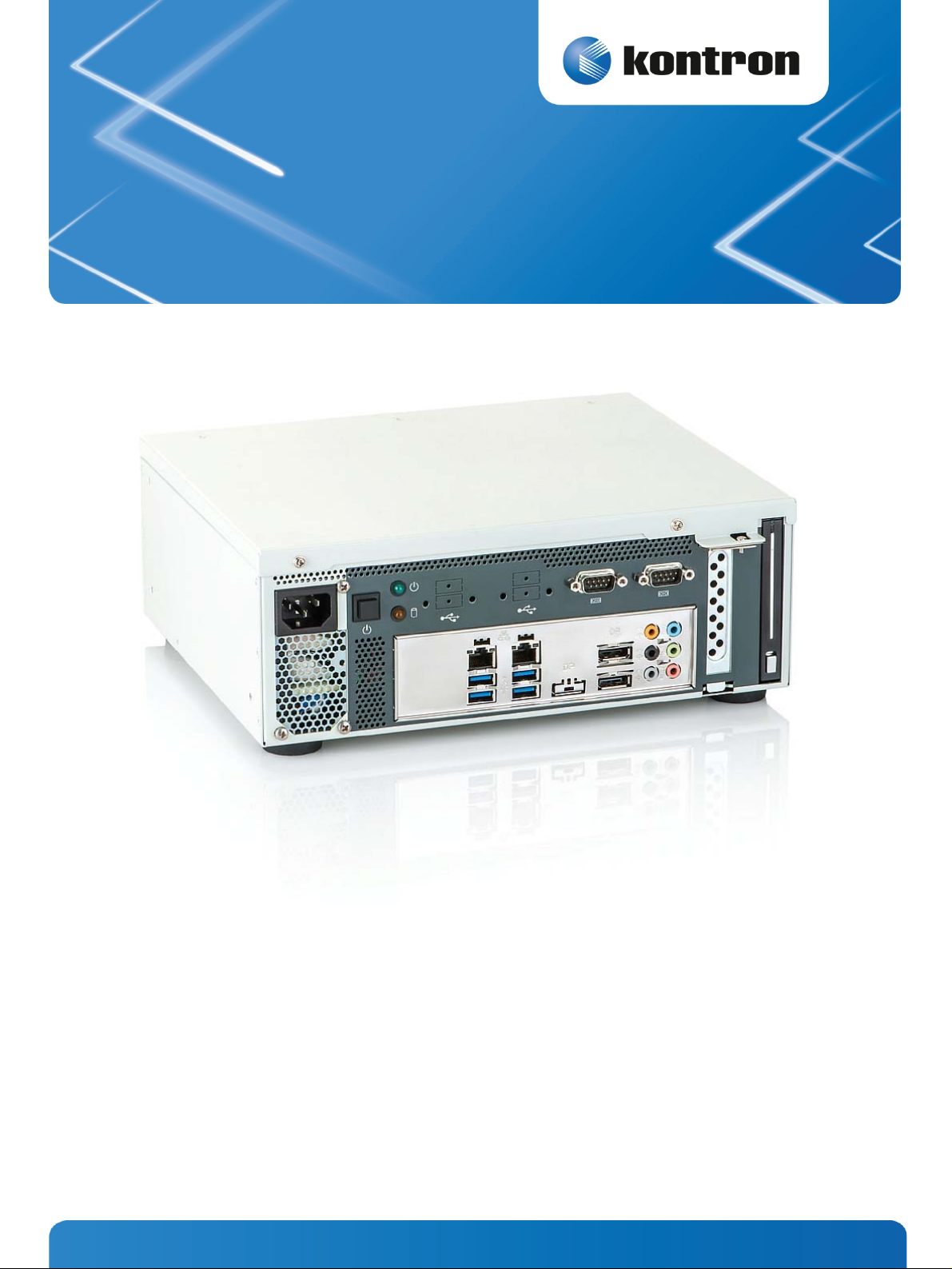
7. Product Description ................................................................................................................................12
7.1. Front Side ............................................................................................................................................13
7.1.1. Power Supply Unit (AC) ....................................................................................................................13
7.1.2. Controls and Indicators....................................................................................................................13
7.1.3. Interfaces on the Front Side..............................................................................................................15
7.2. Rear Side .............................................................................................................................................17
7.3. Right/Left and Top Side .......................................................................................................................... 18
7.4. Bottom side .........................................................................................................................................19
8. Handling internal Components .................................................................................................................20
8.1.1. Opening and Closing the KBox B-101..................................................................................................20
8.1.2. Installing/Removing Expansion Cards.................................................................................................21
8.1.3. Replacing the Lithium Battery ...........................................................................................................22
9. Setting up the KBox B-101.......................................................................................................................23
9.1. KBox B-101 – Desktop Version .................................................................................................................24
9.2. Wall/Table Mounting using the Brackets ....................................................................................................25
9.2.1. Brackets for Wall Mounting ...............................................................................................................25
9.2.2. Brackets for Table Mounting .............................................................................................................26
10. Starting Up ..........................................................................................................................................27
10.1. AC Power Connection............................................................................................................................27
10.2. Operating System and Hardware Component Drivers...................................................................................28
11. Maintenance and Prevention ..................................................................................................................29
12. Technical Data ......................................................................................................................................30
12.1. Electrical Specifications ........................................................................................................................31
www.kontron.com 1
Page 4

1. Table of Contents KBox B-101 – User’s Guide (Version 1.00)
12.2. Mechanical Specifications..................................................................................................................... 31
12.2.1. KBox B-101 Desktop Dimensions ..................................................................................................... 31
12.2.2. Dimensions for Wall Mounting......................................................................................................... 32
12.2.3. Dimensions for Table Mounting ....................................................................................................... 33
12.3. Environmental Specifications ................................................................................................................ 34
12.4. CE Directives and Standards .................................................................................................................. 35
13. Standard Interfaces – Pin Assignments ................................................................................................... 36
13.1.1. Serial Interfaces COM 1 and COM 2 (RS232)........................................................................................ 36
13.1.2. DP Connector (DisplayPort) ............................................................................................................ 36
13.1.3. USB 2.0 Port................................................................................................................................ 37
13.1.4. USB3.0 Port................................................................................................................................. 37
14. Technical Support................................................................................................................................. 38
14.1. Returning Defective Merchandise ........................................................................................................... 38
1.1. Table of Figures
Fig. 1: Front view ........................................................................................................................................11
Fig. 2: Rear view .........................................................................................................................................11
Fig. 3: Bottom view .....................................................................................................................................12
Fig. 4: Right side view ..................................................................................................................................12
Fig. 5: Front view ........................................................................................................................................12
Fig. 6: Left side view ....................................................................................................................................12
Fig. 7: Top view...........................................................................................................................................12
Fig. 8: Rear view .........................................................................................................................................12
Fig. 9: KBox B-101 – front view......................................................................................................................13
Fig. 10: KBox B-101 – Controls and Indicators ..................................................................................................13
Fig. 11: External interfaces of the integrated motherboard .................................................................................15
Fig. 12: Rear side of the KBox B-101 ...............................................................................................................17
Fig. 13: Right side of the chassis ....................................................................................................................18
Fig. 14:Top side of the chassis .......................................................................................................................18
Fig. 15: Left side of the chassis ......................................................................................................................18
Fig. 16: Bottom side (shown as desktop version)...............................................................................................19
Fig. 17: Expansion Slots of the KBox B-101 ......................................................................................................21
Fig. 18: Lithium battery................................................................................................................................22
Fig. 19: Desktop version of the KBox B-101, with rubber feet attached ..................................................................24
Fig. 20: KBox B-101 with brackets for wall mounting installed .............................................................................25
Fig. 21: KBox B-101 with brackets for table mounting installed ...........................................................................26
Fig. 22: AC input connector on the front side of the chassis .................................................................................27
Fig. 23: Dimensions in the front view (desktop version)......................................................................................31
2 www.kontron.com
Page 5

1. Table of Contents KBox B-101 – User’s Guide (Version 1.00)
Fig. 24: Dimensions in the side view and top view (desktop version)..................................................................... 31
Fig. 25: Dimensions in the front view (wall mounting) ....................................................................................... 32
Fig. 26: Dimensions in the side view (wall mounting) ........................................................................................ 32
Fig. 27: Dimensions in the front view (table mounting)...................................................................................... 33
Fig. 28: Dimensions in the side view (table mounting) ....................................................................................... 33
www.kontron.com 3
Page 6

2. Introduction KBox B-101 – User’s Guide (Version 1.00)
2. Introduction
Kontron would like to point out that the information contained in this manual may be subject to technical alteration,
particularly as a result of the constant upgrading of Kontron products. The attached documentation does not entail any
guarantee on the part of Kontron with respect to technical processes described in the manual or any product
characteristics set out in the manual. Kontron does not accept any liability for any printing errors or other inaccuracies in
the manual unless it can be proven that Kontron is aware of such errors or inaccuracies or that Kontron is unaware of
these as a result of gross negligence and Kontron has failed to eliminate these errors or inaccuracies for this reason.
Kontron expressly informs the user that this manual only contains a general description of technical processes and
instructions which may not be applicable in every individual case. In cases of doubt, please contact Kontron.
This manual is protected by copyright. All rights are reserved by Kontron. Copies of all or part of this manual or
translations into a different language may only be made with the prior written consent of Kontron. Kontron points out
that the information contained in this manual is constantly being updated in line with the technical alterations and
improvements made by Kontron to the products and thus this manual only reflects the technical status of the products by
Kontron at the time of printing.
© 2014 by Kontron Europe GmbH
Lise-Meitner-Str. 3-5
86156 Augsburg
Germany
4 www.kontron.com
Page 7
2. Introduction KBox B-101 – User’s Guide (Version 1.00)
2.1. Symbols used in this Manual
Symbol Meaning
This symbol indicates the danger of injury to the user or the risk of damage to the product if the
corresponding warning notices are not observed.
This symbol indicates that the product or parts thereof may be damaged if the corresponding warning
notices are not observed.
This symbol indicates general information about the product and the user manual.
This symbol indicates detail information about the specific product configuration.
This symbol precedes helpful hints and tips for daily use.
www.kontron.com 5
Page 8

3. Important Instructions KBox B-101 – User’s Guide (Version 1.00)
3. Important Instructions
This manual provides important information required for the proper operation of the KBox B-101!
This chapter contains instructions which must be observed when working with the KBox B-101.
3.1. Warranty Note
Due to their limited service life, parts which by their nature are subject to a particularly high degree of wear (wearing
parts) are excluded from the warranty beyond that provided by law. This applies to the CF card, for example.
3.2. Exclusion of Accident Liability Obligation
Kontron shall be exempted from the statutory accident liability obligation if the user fails to observe the included
document: “General Safety Instructions for IT Equipment” the hints in this manual or eventually the warning signs label
on the device.
3.3. Liability Limitation / Exemption from the Warranty Obligation
In the event of damage to the device caused by failure to observe the included document “General Safety Instructions for
IT Equipment”, the hints in this manual or eventually the warning signs label on the device, Kontron shall not be required
to honor the warranty even during the warranty period and shall be exempted from the statutory accident liability
obligation..
6 www.kontron.com
Page 9

4. General Safety Instructions for IT Equipment KBox B-101 – User’s Guide (Version 1.00)
4. General Safety Instructions for IT Equipment
Please read this chapter carefully and take careful note of the instructions, which have been compiled for
your safety and to ensure to apply in accordance with intended regulations. If the following general
safety instructions are not observed, it could lead to injuries to the operator and/or damage of the
product; in cases of nonobservance of the instructions Kontron is exempt from accident liability, this
also applies during the warranty period.
The product has been built and tested according to the basic safety requirements for low voltage (LVD) applications and
has left the manufacturer in safety-related, flawless condition. To maintain this condition and to also ensure safe
operation, the operator must not only observe the correct operating conditions for the product but also the following
general safety instructions:
The product must be used as specified in the product documentation, in which the instructions for safety for the
product and for the operator are described. These contain guidelines for setting up, installation and assembly,
maintenance, transport or storage.
The on-site electrical installation must meet the requirements of the country's specific local regulations.
If a power cable comes with the product, only this cable should be used. Do not use an extension cable to connect the
product.
To guarantee that sufficient air circulation is available to cool the product, please ensure that the ventilation
openings are not covered or blocked. If a filter mat is provided, this should be cleaned regularly. Do not place the
system close to heat sources or damp places. Make sure the system is well ventilated.
Only devices or parts which fulfill the requirements of SELV circuits (Safety Extra Low Voltage) as stipulated by
IEC 60950-1 may be connected to the available interfaces.
Before opening the device, make sure that the device is disconnected from the mains.
Switching off the device by its power button does not disconnect it from the mains. Complete disconnection is only
possible if the power cable is removed from the wall plug or from the device. Ensure that there is free and easy access
to enable disconnection.
The device may only be opened for the insertion or removal of add-on cards (depending on the configuration of the
system). This may only be carried out by qualified operators.
If extensions are being carried out, the following must be observed:
• all effective legal regulations and all technical data are adhered to
• the power consumption of any add-on card does not exceed the specified limitations
• the current consumption of the system does not exceed the value stated on the product label.
Only original accessories that have been approved by Kontron can be used.
Please note: safe operation is no longer possible when any of the following applies:
• the device has visible damages or
• the device is no longer functioning
In this case the device must be switched off and it must be ensured that the device can no longer be operated.
www.kontron.com 7
Page 10
4. General Safety Instructions for IT Equipment KBox B-101 – User’s Guide (Version 1.00)
Additional safety instructions for DC power supply circuits
To guarantee safe operation of devices with DC power supply voltages larger than 60 volts DC or a power consumption
larger than 240 VA, please observe that:
• the device is set up, installed and operated in a room or enclosure marked with “RESTRICTED ACCESS”, if there are no
safety messages on product as safety signs and labels on the device itself.
• no cables or parts without insulation in electrical circuits with dangerous voltage or power should be touched
directly or indirectly
• a reliable protective earthing connection is provided
• a suitable, easily accessible disconnecting device is used in the application (e.g. overcurrent protective device), if
the device itself is not disconnectable
• a disconnect device, if provided in or as part of the equipment, shall disconnect both poles simultaneously
• interconnecting power circuits of different devices cause no electrical hazards
A sufficient dimensioning of the power cable wires must be selected – according to the maximum electrical
specifications on the product label – as stipulated by EN60950-1 or VDE0100 or EN60204 or UL508 regulations.
The devices do not generally fulfill the requirements for "centralized DC power systems“ (UL 60950-1, Annex NAB; D2)
and therefore may not be connected to such devices!
4.1. Electrostatic Discharge (ESD)
A sudden discharge of electrostatic electricity can destroy static-sensitive devices or micro-circuitry. Proper packaging
and grounding techniques are necessary precautions to prevent damage. Always take the following precautions:
1. Transport boards in static-safe containers such as boxes or bags.
2. Keep electrostatic sensitive parts in their containers until they arrive at the ESD-safe workplace.
3. Always be properly grounded when touching a sensitive board, component, or assembly.
4. Store electrostatic-sensitive boards in protective packaging or on antistatic mats.
4.1.1. Grounding Methods
The following measures help to avoid electrostatic damages to the device:
1. Cover workstations with approved antistatic material. Always wear a wrist strap connected to workplace as well as
properly grounded tools and equipment.
2. Use anti-static mats, heel straps, or air ionizes to give added protection.
3. Always handle electrostatic sensitive components by their edge or by their casing.
4. Avoid contact with pins, leads, or circuitry.
5. Turn off power and input signals before inserting and removing connectors or connecting test equipment.
6. Keep work area free of non-conductive materials such as ordinary plastic assembly aids and styrofoam.
7. Use field service tools such as cutters, screwdrivers, and vacuum cleaners which are conductive.
8. Always place drives and boards PCB-assembly-side down on the foam.
8 www.kontron.com
Page 11
4. General Safety Instructions for IT Equipment KBox B-101 – User’s Guide (Version 1.00)
4.2. Instructions for the Lithium Battery
The installed motherboard is equipped with a Lithium battery. When replacing the lithium battery, please follow the
corresponding instructions in the subsection
Caution
Danger of explosion when replacing with wrong type of battery. Replace only with the same or equivalent
type recommended by the manufacturer. The lithium battery type must be UL recognized.
Do not dispose of lithium batteries in general trash collection. Dispose of the battery according to the
local regulations dealing with the disposal of these special materials, (e.g. to the collecting points for
dispose of batteries).
8.1.2 “Replacing the Lithium Battery”.
www.kontron.com 9
Page 12

5. Electromagnetic Compatibility (Class A Device) KBox B-101 – User’s Guide (Version 1.00)
5. Electromagnetic Compatibility (Class A Device)
5.1. Electromagnetic Compatibility (EU)
This product is intended only for use in industrial areas. The most recent version of the EMC guidelines (EMC Directive
2004/108/EC) and/or the German EMC laws apply. If the user modifies and/or adds to the equipment (e.g. installation of
add-on cards) the prerequisites for the CE conformity declaration (safety requirements) may no longer apply.
Warning!
This is a class A product. In domestic environment this product may cause radio interference in which case the user may
be required to take adequate measures.
5.2. FCC Statement (USA)
This equipment has been tested and found to comply with the limits for a Class A digital device, pursuant to Part 15 of the
FCC Rules. These limits are designed to provide reasonable protection against harmful interference when the equipment is
operated in commercial environment. This equipment generates, uses, and can radiate radio frequency energy and, if not
installed and used in accordance with the instruction manual, may cause harmful interference to radio communications.
Operation of this equipment in residential area is likely to cause harmful interference in which case the user will be
required to correct the interference at his own expense.
5.3. EMC Compliance (Canada)
The method of compliance is self-declaration to Canadian standard ICES-003:
(English): This Class A digital apparatus complies with the Canadian ICES-003.
(French): Cet appareil numérique de la class A est conforme à la norme NMB-003 du Canada.
10 www.kontron.com
Page 13

6. Scope of Delivery KBox B-101 – User’s Guide (Version 1.00)
6. Scope of Delivery
KBox B-101 (corresponding to the ordered system configuration)
Rubber feet (self-adhesive)
AC power cable
General Safety Instructions for IT Equipment
Optional Parts
Brackets for wall mounting
Brackets for table mounting
6.1. Type Label and Product Identification
The type label (product name, serial number) of your KBox B-101 system is located at the left side of the device (refer to
Fig. 15).
Fig. 1: Front view Fig. 2: Rear view
www.kontron.com 11
Page 14
7. Product Description KBox B-101 – User’s Guide (Version 1.00)
7. Product Description
The KBox B-101 expands the Kontron line of computers - KBox series. The system is equipped with a Mini-ITX
®
Motherboard (with support for Intel
Core™ i7/i5/i3, 4. generation and Pentium® processors).
The KBox B-101 is a compact, actively cooled box PC for industrial control and automation applications.
The rated voltage of the mains can be found on the type label. The type label is located at the left side of the device. For
the configuration of your KBox B-101 please follow the ordering options specified in “Configuration Guides – KBox
Series“ on our web site
www.kontron.com.
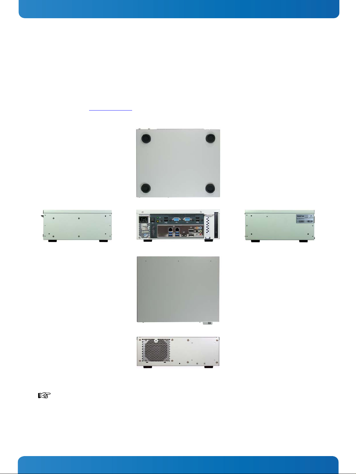
Fig. 3: Bottom view
Fig. 4: Right side view Fig. 5: Front view Fig. 6: Left side view
Fig. 7: Top view
Fig. 8: Rear view
Outside a fire enclosure, the device may only be operated in horizontal position. A vertical operating
position is only allowed if the device is installed inside a fire enclosure (also if wall-mounted). When
switching on the KBox B-101, make sure that the air openings on the front side (
rear side (
Fig. 12, pos. 3) of the chassis are not obstructed (covered) by any objects.
Fig. 9, pos. 4) and the
12 www.kontron.com
Page 15

7. Product Description KBox B-101 – User’s Guide (Version 1.00)
7.1. Front Side
AC IN power connector
1
2 Controls and indicators
2 31 4 5 6
74
Fig. 9: KBox B-101 – front view
4 Ventilation openings at the front side
5 PCIE x16 Slot
3 Additional interface connectors
(routed from the internal onboard interfaces)
7.1.1. Power Supply Unit (AC)
The 3-pin connector (
section
10.1 „AC Power Connection“.
Fig. 9, pos. 1) provides the power connection to a mains socket via a power cord. Please observe
7.1.2. Controls and Indicators
2
3
Fig. 10: KBox B-101 – Controls and Indicators
1
6 Optional drive bay for removable HDD/SSD
7 Interfaces of the installed motherboard
1 Power button
2 Power LED
3 HDD LED
www.kontron.com 13
Page 16

7. Product Description KBox B-101 – User’s Guide (Version 1.00)
7.1.2.1. Power Button
Press this button (
Fig. 10, pos. 1) to turn the system on and off.
Prerequisite:
The KBox B-101 must be connected to an appropriate AC mains power source.
Caution!
Please observe that turning OFF the system via the power button (see
disconnect the platform from the AC mains power source.
Even when the system is turned off via the power button (see
voltage of 5 VSb on the motherboard.
The unit is only completely disconnected from the mains when the power cord is disconnected either
from the mains power source or from the unit. Therefore, the power cord and its connectors must always
remain easily accessible. The outlet of the AC power source must be located near to the device and be
easily accessible.
7.1.2.2. Power LED and HDD Activity LED
The power LED (
Fig. 10, pos. 2) and the HDD LED (Fig. 10, pos. 3) are located on the front side of the KBox B-101 and
indicate the system status.
Fig. 10, pos.1) does not
Fig. 10, pos.1) there is still a standby-
Power LED
(green)
HDD-LED
(yellow)
This LED (
Fig. 10, pos. 2) lights up green when the system is turned on by the power button.
Prerequisite:
The system must be connected to the AC power source, using the power cable.
This LED (
Fig. 10, pos. 3) lights up during hard disk activity.
Do not press the eject button of the (optional) removable HDD/SSD, while the drive LED is lit or is
flashing.
14 www.kontron.com
Page 17
7. Product Description KBox B-101 – User’s Guide (Version 1.00)
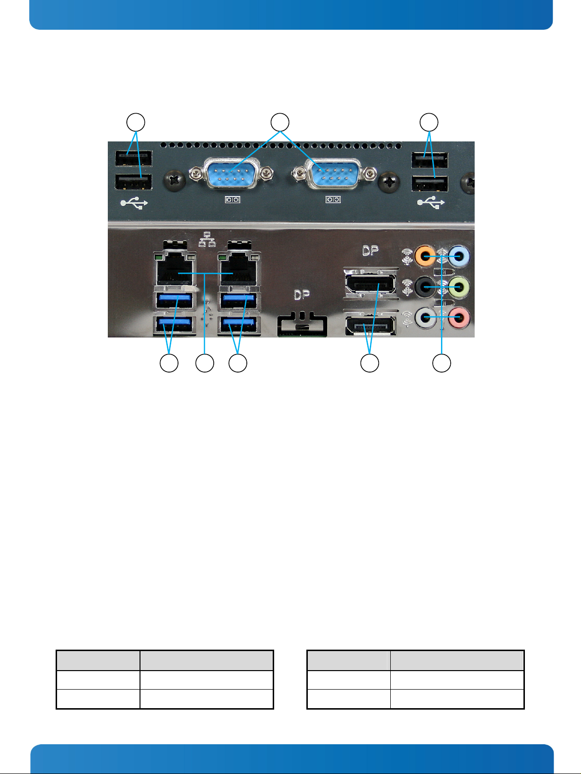
7.1.3. Interfaces on the Front Side
1
2 1
3 54
Fig. 11: External interfaces of the integrated motherboard
1
4x USB 2.0 port (USB4 - USB7)
2 2x serial port (COM1, COM2)
3 2x USB 2.0 port (USB2, USB3)
4 2x LAN port (RJ45) (10/100/1000Mbps)
5 2x USB 3.0 port (USB0, USB1)
6 2x DisplayPort Connector (DP0, DP1)
7 Audio connectors
7.1.3.1. USB Ports
The system is equipped with six USB 2.0 ports and two USB 3.0 ports (
7.1.3.2. Serial Ports (COM1, COM2)
The serial ports COM1 and COM2 (
Fig. 11, pos. 2) consist of a 9-pin, RS232-configured D-SUB connectors that allow the
connection of serial peripherals.
7.1.3.3. LAN Ports (ETH1, ETH2)
7 6
Fig. 11, pos. 1, 3 and 5).
These ports (
Fig. 11, pos. 4) consist of RJ45 connectors with integrated LEDs and support a transfer rate of
10/100/1000Mbps.
Left LED Color Link Status Right LED Color Link Speed
Off No Link Off 10 Base-T/100 Base-T
Green blinking Link is established
Yellow 1000 Base-T
www.kontron.com 15
Page 18

7. Product Description KBox B-101 – User’s Guide (Version 1.00)
7.1.3.4. Display Port Connector
Two external (digital) displays can be connected to the DisplayPort connectors (DP0, DP1) (
Appropriate Monitors can be connected directly to the DisplayPort connectors using DisplayPort
cables. To avoid disturbances, it is recommended not to use any adapters (e.g. DisplayPort/DVI or
DisplayPort/HDMI adapter) at the DisplayPort connectors.
7.1.3.5. Audio Connectors
Depending on the operating system and the audio software, the six audio connectors (
Fig. 11, pos. 7) can be operated as
audio input or output jacks (e.g. Line-In, Line-Out, Mic-In, 5.1 surround etc.).
Fig. 11, pos. 6).
16 www.kontron.com
Page 19

7. Product Description KBox B-101 – User’s Guide (Version 1.00)
7.2. Rear Side
1 Rear side of the KBox B-101
2 Rubber feet (desktop version)
2
1
Fig. 12: Rear side of the KBox B-101
3 Air exhaust openings of the internal fan
4 Cuttings for the optional installation of two Reverse
(RP) SMA connectors by the customer (for mounting
optional WLAN/WiFi antennas)
4
2 3
www.kontron.com 17
Page 20

7. Product Description KBox B-101 – User’s Guide (Version 1.00)
7.3. Right/Left and Top Side
At the right and left side of the chassis, the threaded holes for attaching the optional mounting brackets are located. In
addition, the type label is attached to the left side of the chassis.
Fig. 13: Right side of the
1 Right side of the chassis
2 Threaded holes for attaching the mounting
2 2 4 31
chassis
brackets
Fig. 14:Top side of the chassis Fig. 15: Left side of the chassis
3 Top side of the chassis (cover)
4 Left side of the chassis (with type label)
18 www.kontron.com
Page 21

7. Product Description KBox B-101 – User’s Guide (Version 1.00)
7.4. Bottom Side
2
1
2
1 Front side with external interfaces of the
installed motherboard
If you intend to convert your device from the desktop version to a wall/table mount version, see also
chapter
9 ”Setting up the KBox B-101”.
Fig. 16: Bottom side (shown as desktop version)
2 Rubber feet (desktop version)
www.kontron.com 19
Page 22

8. Handling internal Components KBox B-101 – User’s Guide (Version 1.00)
8. Handling internal Components
This chapter contains important information that you must read before accessing internal components. You must follow
these procedures properly when handling any board components of the KBox B-101.
Before installing/removing an add-on card, please pay attention to the following information:
Please observe the “General Safety Instructions for IT-Equipment” provided with the system and
the installation instructions in this manual (see also chapter
The installation/removal of add-on cards may only be performed by a qualified person, according
to the description in this manual.
Before removing the cover of the device, make sure that the device is switched off and
disconnected from the power supply.
Before you upgrade the KBox B-101 with add-on cards, pay attention to the power specifications
in chapter
does not exceed 5 W.
Please follow the safety instructions for components that are sensitive to electrostatic discharge
(ESD). Failure to observe this warning notice may result in damage to the device or the latter’s
components.
Please pay attention to the manufacturer’s instructions before installing/removing an add-on
card.
12 “Technical Data” and make sure that the power consumption of the add-on cards
4 and 9).
8.1.1. Opening and Closing the KBox B-101
In order to install or to remove optional hardware or to change the DIP switch settings, the KBox B-101 needs to be
opened. For opening and closing the KBox B-101, please perform the following steps:
Before opening the KBox B-101, the system must be switched off and disconnected from the main power
supply. Also disconnect peripheral devices from the KBox B-101. Before you begin, ensure that you have
a clean, flat and ESD-safe surface to work on.
1. Close all applications. Shut down the system properly and disconnect the power cord from the power source.
Disconnect all peripherals.
2. Place the KBox B-101 on a flat, clean surface.
3. Remove the two screws at the front edge of the cover.
4. Pull/slide the cover to the front a few centimeters (towards the screws removed in step 3) and lift off the cover. Now
all internal components inside the chassis can be accessed.
5. For closing the KBox B-101, proceed in reverse order: Place the cover on the cassis and push/slide it backwards
(towards the rear side of the chassis) as far as it will go. Secure the cover with the two screws removed in step 3.
20 www.kontron.com
Page 23

8. Handling internal Components KBox B-101 – User’s Guide (Version 1.00)
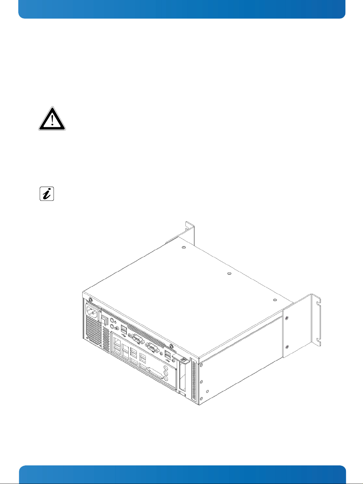
8.1.2. Installing/Removing Expansion Cards
Before installing an expansion card, please note the information provided by the manufacturer.
1
2
3
4
Fig. 17: Expansion Slots of the KBox B-101
1 PCIe slot
2 Slot bracket for PCIe slot
3 mSATA slot
4 Mini-PCIe slot
In order to install/remove an expansion card, perform the following steps:
1. Open the KBox B-101, as described in subsection
8.1.1”Opening and Closing the KBox B-101” (steps 1 to 4).
2. After removing the cover, the PCIe slot, the Mini PCI Express slot and the mSATA slot are easily accessible (see
). Now, appropriate expansion cards can be installed.
17
Please note that either only a full-size Mini PCIe module or a full-size mSATA module or both, a half-
size Mini PCIe module and a half-size mSATA module can be installed at a time, since both slots share
the same installation space (1x full-size/2x half-size) on the motherboard!
3. Close the KBox B-101 as described in subsection
8.1.1”Opening and Closing the KBox B-101” (step 5).
Fig.
www.kontron.com 21
Page 24

8. Handling internal Components KBox B-101 – User’s Guide (Version 1.00)
8.1.3. Replacing the Lithium Battery
The integrated motherboard of your system is equipped with a lithium battery. To replace the battery, please proceed as
follows:
1. Open the unit as described in subsection
2. Remove the lithium battery from the holder by pulling the ejector spring outwards.
3. Place a new lithium battery into the battery holder.
4. Pay attention to the polarity of the battery.
5. The lithium battery must be replaced with an identical battery or a battery type recommended by Kontron (Lithium
battery 3.0 V for RTC, type: CR2032).
6. Close the device, as described in the subsection
8.1.1”Opening and Closing the KBox B-101” (step 1-4).
8.1.1 “Opening and Closing the KBox B-101” (step 5).
-
Fig. 18: Lithium battery
+
Lithium battery
Caution
Danger of explosion when replacing with wrong type of battery. Replace only with the same or equivalent
type recommended by the manufacturer. The Lithium battery type must be UL recognized.
Do not dispose of lithium batteries in general trash collection. Dispose of the battery according to the
local regulations dealing with the disposal of these special materials, (e.g. to the collecting points for
disposal of batteries).
22 www.kontron.com
Page 25

9. Setting up the KBox B-101 KBox B-101 – User’s Guide (Version 1.00)
9. Setting up the KBox B-101
Important Instructions!
In order to setting-up, installing/removing the KBox B-101 platform, please observe the instructions
described in this manual.
The device may only be set up and installed by maintenance personnel responsible for this area (and
aware of the dangers involved).
Outside a fire enclosure, the device may only be operated in horizontal position.
A vertical operating position is only allowed if the device is installed inside a fire enclosure.
Please observe all specified dimensions required for mounting included in the drawing with outline
dimensions for the KBox B-101 platform. The corresponding drawing can be downloaded from our web
www.kontron.com by selecting the product name.
site
Leave at least 100 mm (approximately 3.937") free space to the front and rear of the unit in order to have
access to the interfaces to connect the peripherals and to operate the power button.
When mounted into a cabinet: the cabinet must have adequate space for the KBox B-101 platform, and
corresponding spaces for air circulation and cable connections (see also section
Specifications
overheating.
Make sure that the ventilation openings of the chassis are not obstructed (covered) by any objects.
For mounting to a table or to a wall: Use only the optional brackets (not included) and the countersunk
M4x6 screws described in the following section. Longer screws can damage the device!
The platform must be firmly attached to a clean flat and solid mounting surface. Use proper fastening
materials suitable for the mounting surface. Ensure that the mounting surface type and the used
mounting solution safely support the load of the KBox B-101 platform and the attached components. It is
recommended to use screws with a diameter of 5 mm (0.197"). The screw type and length as well as
accessories like anchors depend on the type and the consistence of the mounting surface (table, wall,
cabinet etc.).
Please follow the local/national regulations for grounding.
The voltage feeds must not be overloaded.
Adjust the cabling and the external overcharge protection to correspond with the electrical data indicated
on the type label.
The type label is located on the left side of the unit (refer to
”). Furthermore, the cabinet must have a sufficient, optionally active ventilation to prevent
Fig. 15).
12.2 “Mechanical
www.kontron.com 23
Page 26

9. Setting up the KBox B-101 KBox B-101 – User’s Guide (Version 1.00)
9.1. KBox B-101 – Desktop Version
For the desktop version, the self-adhesive rubber feet (included) have to be attached to the bottom side of the device.
When setting up the device, make sure that the ventilation openings on the front and rear side of the chassis are not
obstructed (covered) by any objects (refer to subsection
12.2.1 “KBox B-101 Desktop Dimensions”).
Fig. 19: Desktop version of the KBox B-101, with rubber feet attached
24 www.kontron.com
Page 27
9. Setting up the KBox B-101 KBox B-101 – User’s Guide (Version 1.00)
9.2. Wall/Table Mounting using the Brackets
In order to mount the KBox B-101 to a wall, on a table or into a cabinet, you may order the corresponding mounting
brackets. You can adapt your desktop KBox B-101 to a wall or table mount system by attaching the appropriate mounting
brackets to the corresponding sides of the KBox B-101.
Please observe the “General Safety Instructions for IT Equipment” (included) and the installation
instructions (refer to the chapters
Outside a fire enclosure, the device may only be operated in horizontal position. A vertical operating
position is only allowed if the device is installed inside a fire enclosure.
9.2.1. Brackets for Wall Mounting
4 and 0).
These brackets (
Fig. 20) are used to mount the KBox B-101 to a wall.
Wall mounting outside a fire enclosure is only allowed in horizontal position (2 operating positions).
Inside a fire enclosure, you may choose which side is facing up or down (4 operating positions). The two
brackets are symmetrical and can be mounted on either the left or right (see also subsection
Dimensions for Wall Mounting”).
“
12.2.2
Fig. 20: KBox B-101 with brackets for wall mounting installed
www.kontron.com 25
Page 28

9. Setting up the KBox B-101 KBox B-101 – User’s Guide (Version 1.00)
9.2.2. Brackets for Table Mounting
These brackets (
Fig. 21) are used to mount the KBox B-101 to a table.
Table outside a fire enclosure is only allowed in horizontal position (2 operating positions). Inside a fire
enclosure, you may choose which side is facing up or down (4 operating positions). The two brackets are
symmetrical and can be mounted on either the left or right (see also subsection
Wall Mounting
”).
12.2.2 “Dimensions for
Fig. 21: KBox B-101 with brackets for table mounting installed
Table mounting (by using the corresponding brackets) is only possible without the rubber feet attached.
Rubber feet that are already attached to the chassis of the KBox B-101 (e.g. when adapting a desktop
version) must be removed before table mounting.
26 www.kontron.com
Page 29
10. Starting Up KBox B-101 – User’s Guide (Version 1.00)
10. Starting Up
The rated voltage of the power supply must correspond with the voltage value on the type label.
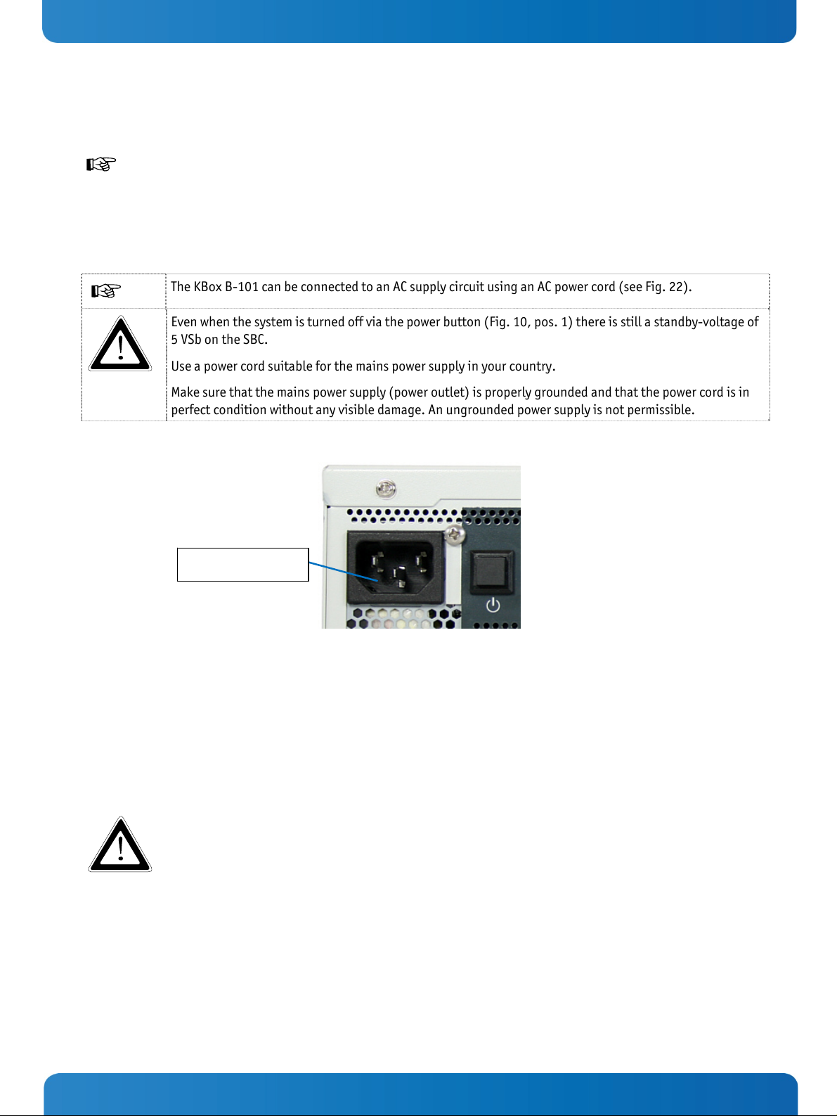
10.1. AC Power Connection
The AC input connector (Fig. 9, pos. 1) is located on the front side of the KBox B-101.
The KBox B-101 can be connected to an AC supply circuit using an AC power cord (see
Even when the system is turned off via the power button (
5 VSb on the SBC.
Use a power cord suitable for the mains power supply in your country.
Make sure that the mains power supply (power outlet) is properly grounded and that the power cord is in
perfect condition without any visible damage. An ungrounded power supply is not permissible.
AC input
Fig. 10, pos. 1) there is still a standby-voltage of
Fig. 22).
Fig. 22: AC input connector on the front side of the chassis
To connect the KBox B-101 to a corresponding AC main power supply, please perform the following steps:
1. Insert the corresponding connector of the supplied AC power cord into the AC input connector (
The AC input connector is located on the front side of the KBox B-101.
2. Connect the AC power cord to an appropriate AC mains socket.
The power cord is used as a disconnecting device (the unit is only completely disconnected from the
mains, when the power cord is disconnected either from the mains or the unit). Therefore, the outlet of
the AC power source must be located near to the device and be easily accessible.
Fig. 9, pos. 1, Fig. 22).
www.kontron.com 27
Page 30

10. Starting Up KBox B-101 – User’s Guide (Version 1.00)
10.2. Operating System and Hardware Component Drivers
Your system can be supplied optionally with a pre-installed operating system.
If you have ordered your KBox B-101 with a pre-installed operating system, all drivers are installed in accordance with the
system configuration ordered (optional hardware components). Your system is fully operational when you switch it on for
the first time. Please pay attention to the following note.
Important information on the use of the pre-installed “WINDOWS 7 ULTIMATE FOR EMBEDDED
SYSTEMS” or “WINDOWS 7 PROFESSIONAL FOR EMBEDDED SYSTEMS“ operating systems:
The terms and conditions for the use of the pre-installed operating systems are specified in the
document “MICROSOFT SOFTWARE LICENSE TERMS”.
You can download this document from our web site
tab/Windows.
If you have ordered The KBox B-101 without a pre-installed operating system, you will need to install the operating
system and the appropriate drivers for the system configuration you have ordered (optional hardware components)
yourself.
You can download the relevant drivers for the installed hardware from our web site at
by selecting the product.
Pay attention to the manufacturer specifications of the operating system and the integrated hardware
components.
www.kontron.com by selecting Product/ Downloads
www.kontron.com
28 www.kontron.com
Page 31

11. Maintenance and Prevention KBox B-101 – User’s Guide (Version 1.00)
11. Maintenance and Prevention
Equipment from Kontron requires only minimum servicing and maintenance for problem-free operation.
For light soiling, clean the KBox B-101 with a dry cloth.
Carefully remove dust from the surface of the cooling fins of the chassis using a clean, soft brush.
Stubborn dirt should be removed using a mild detergent and a soft cloth.
www.kontron.com 29
Page 32

12. Technical Data KBox B-101 – User’s Guide (Version 1.00)
12. Technical Data
KBox B-101
Motherboard
Supported Processors
RAM
Chipset
Storage Media
BIOS
Interfaces
Internal Onboard Slots
Controls
(at the front side)
Indicators
(at the front side)
Kontron KTH81Mini-ITX motherboard
®
4th Gen. Core™ i7/i5/i3 and Pentium® processors
Intel
max.16 GB (2 x 8 GB) DDR3/DDR3L
®
PCH H81
Intel
1x HDD or SSD
AMI
Interfaces at the front side:
2x DisplayPort
2x Serial Interface (RS232)
8x USB: 6x USB 2.0; 2x USB 3.0
2x LAN (10/100/1000Mbps)
6x Audio connectors (3.5mm jack plug)
1x full-size Mini PCIe x1, 1x mSATA port , 1x PCIe x16 Low Profile
Power button
Power LED
HDD LED
AC IN Connector
(at the front side)
Leistungsaufnahme pro
Steckplatz (Mini PCIexpress)
Weight
Rated Voltage Range
The corresponding document “Configuration Guide” and the manual of the installed SBC can be
downloaded from our web site:
3-pin IEC socket (IEC 60320 C14)
Max. 5 W
Approx. 4 kg
See type label
www.kontron.com by selecting the product.
30 www.kontron.com
Page 33
12. Technical Data KBox B-101 – User’s Guide (Version 1.00)
12.1. Electrical Specifications
The corresponding electrical specifications for your KBox B-101 can be found on the type label of the system. The type
label is located on the left side of the unit (refer to
Fig. 15).
12.2. Mechanical Specifications
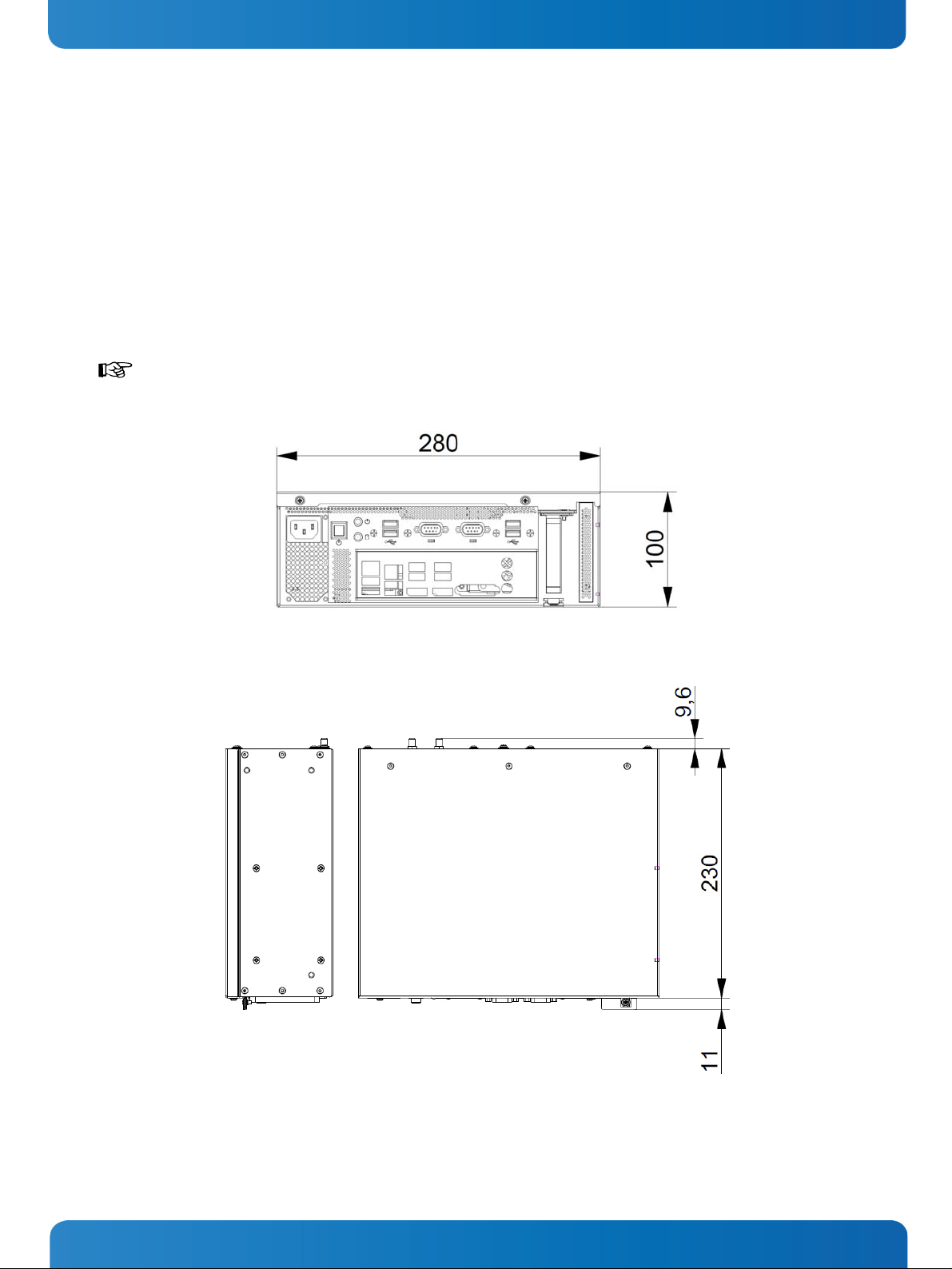
12.2.1. KBox B-101 Desktop Dimensions
For sufficient air circulation, make sure that the ventilation openings of the chassis are not obstructed
(covered) by any objects.
Fig. 23: Dimensions in the front view (desktop version)
Fig. 24: Dimensions in the side view and top view (desktop version)
www.kontron.com 31
Page 34

12. Technical Data KBox B-101 – User’s Guide (Version 1.00)
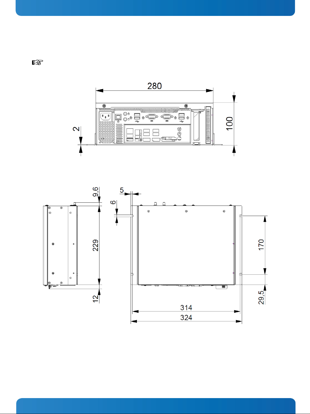
12.2.2. Dimensions for Wall Mounting
(covered) by any objects. The wall mounting brackets provide enough space between the wall and the
chassis (for the fan on the rear side of the chassis) (see
Fig. 26).
Fig. 25: Dimensions in the front view (wall mounting)
For sufficient air circulation, make sure that the ventilation openings of the chassis are not obstructed
Fig. 26: Dimensions in the side view (wall mounting)
32 www.kontron.com
Page 35
12. Technical Data KBox B-101 – User’s Guide (Version 1.00)
12.2.3. Dimensions for Table Mounting
(covered) by any objects.
Fig. 27: Dimensions in the front view (table mounting)
For sufficient air circulation, make sure that the ventilation openings of the chassis are not obstructed
Fig. 28: Dimensions in the side view (table mounting)
www.kontron.com 33
Page 36

12. Technical Data KBox B-101 – User’s Guide (Version 1.00)
12.3. Environmental Specifications
Operating Temperature
Storage/Transit Temperature
Rel. Humidity (Operating)
0 … +45 °C (32 … 113 °F)
-25 … +70 °C (-40 … +185 °F)
95% @ 40 °C (non-condensing)
34 www.kontron.com
Page 37

12. Technical Data KBox B-101 – User’s Guide (Version 1.00)
12.4. CE Directives and Standards
CE Directive
Electrical Safety
Electromagnetic
Compatibility (EMC)
CE Marking
RoHS II Directives
Electrical Safety Harmonized Standards
CB Scheme
EUROPE
U.S.A. / CANADA
EMC Harmonized Standards
EU
General Product Safety Directive (GPSD) 2001/95/EC
Low Voltage Directive (LVD) 2006/95/EC
EMC Directive 2004/108/EC
CE Directive 93/68/EEC
2011/65/EU
CB Certification
Information technology equipment - Safety - Part 1: General requirements
EN 60950-1+ A11
To meet UL60950-1 / CSA C22.2- No. 60950-1-7
Generic emission standard for industrial environments (Emission):
EN 61000-6-4
U.S.A.
CANADA
Generic standards - Immunity for industrial environments (Immunity):
EN 61000-6-2
FCC 47 CFR Part 15, Class A
ICES-003, Class A
www.kontron.com 35
Page 38

13. Standard Interfaces – Pin Assignments KBox B-101 – User’s Guide (Version 1.00)
13. Standard Interfaces – Pin Assignments
Low-active signals are indicated by a minus sign.
13.1.1. Serial Interfaces COM 1 and COM 2 (RS232)
Pin Signal Name 9-pin D-SUB Connector
1 DCD (Data Carrier Detect)
2 RXD (Receive Data)
3 TXD (Transmit Data)
4 DTR (Data Terminal Ready)
5 GND (Signal Ground)
6 DSR (Data Set Ready)
7 RTS (Request to Send)
8 CTS (Clear to Send)
9 RI (Ring Indicator)
13.1.2. DP Connector (DisplayPort)
Pin# Signal Name DisplayPort Signal Name Pin#
1 ML Lane 0 (p) GND (ML Lane 0) 2
3 ML Lane 0 (n) Lane 1 (p) 4
5 GND (ML Lane 1) Lane 1 (n) 6
7 Lane 2 (p) GND (ML Lane 2) 8
9 Lane 2 (n) Lane 3 (p) 10
11 GND (ML Lane 3) Lane 3 (n) 12
13 AUX SEL# Pull-down to GND 14
15 AUX CH (p) GND (AUX CH) 16
17 AUX CH (n) Hot Plug 18
3.3V (DDC EEPROM power
19 GND (GND_DDC)
36 www.kontron.com
500 mA fused
20
Page 39

13. Standard Interfaces – Pin Assignments KBox B-101 – User’s Guide (Version 1.00)
13.1.3. USB 2.0 Port
Pin Signal Name 4-pin USB Connector
Typ A Version 2.0
1 VCC
2 Data-
3 Data+
4 GND
13.1.4. USB3.0 Port
Pin Signal Name
USB 2.0 Contacts USB 3.0 Contacts
1 VCC, fused (900 mA max.)
2 Data-
3 Data+
4 GND
5 StdA_SSRX-
6 StdA_SSRX+
7 GND_DRAIN
8 StdA_SSTX-
9 StdA_SSTX+
9-pin USB Connector
Type A Version 3.0/2.0
www.kontron.com 37
Page 40

14. Technical Support KBox B-101 – User’s Guide (Version 1.00)
14. Technical Support
For technical support, please contact our Technical Support department:
e-mail:
Web:
support@kontron.com
http://www.kontron.com/support
Make sure you have the following information on hand when you call:
• the unit part id number (PN),
• the serial number (SN) of the unit; the serial number can be found on the type label, placed on the right side of the
system.
Be ready to explain the nature of your problem to the service technician.
If you have questions about Kontron or our products and services, you can reach us by the above-mentioned telephone
number and on e-mail address or at:
www.kontron.com .
14.1. Returning Defective Merchandise
Please follow these steps before you return any merchandise to Kontron:
1. Download the corresponding form for returning a device with an RMA No. [RMA (Return of Material Authorization)]
from our website
an RMA No.
e-mail:
www.kontron.com / Support /.RMA Information; contact our Customer Service department to obtain
service@kontron.com
2. Ensure that you have received an RMA number from Kontron Customer Services before returning any device. Write this
number clearly on the outside of the package.
3. Describe the fault that has occurred.
4. Please provide the name and telephone number of a person we can contact to obtain more information, where
necessary. Where possible, please enclose all the necessary customs documents and invoices.
5. When returning a device:
• Pack it securely in its original box.
• Enclose a copy of the RMA form with the consignment.
Corporate Offices
Europe, Middle East & Africa
Lise-Meitner-Str. 3-5
86156 Augsburg
Germany
Tel.: +49 (0)821/ 0
Fax: +49 (0)821/ 111
info@kontron.com
North America
14118 Stowe Drive
Poway, CA 92064-7147
USA
Tel.: +1 888 294 4558
Fax: +1 858 677 0898
info@us.kontron.com
Asia Pacific
17 Building,Block #1,ABP.
188 Southern West 4th Ring
Beijing 100070, P.R.China
Tel.: + 86 10 63751188
Fax: + 86 10 83682438
info@kontron.cn
38 www.kontron.com
 Loading...