

Kontron AT8402 User Manual
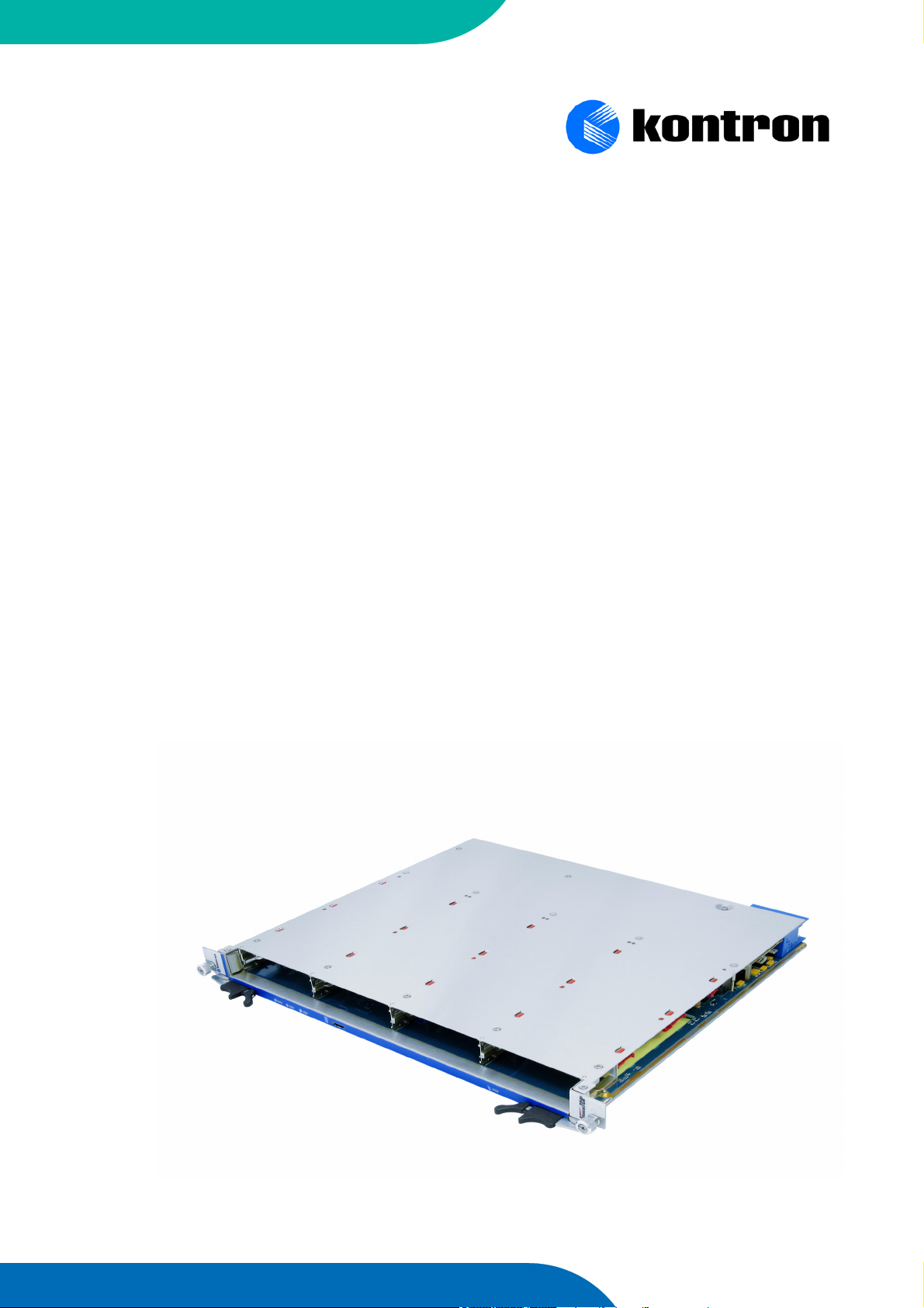
AT8402 USER GUIDE
AdvancedTCA
2.3.1 Revision Index
February 2009 Date of Issue
Revision History
Publication Title: AT8402 User Guide
ID Number: M5306_TECH_1
Rev.
Index
2.3 Initial Issue AT8402 based on AT8400 User Guide V2.3 June, 2007
2.3.1 changed option 2 for option 3 in section 1.1 and 3.1 February 2009
Brief Description of Changes Date of Issue
Imprint
Kontron AG may be contacted via the following:
North America EMEA
Kontron Canada, Inc. Kontron Modular Computers GmbH
616 Curé Boivin Sudetenstrasse 7
Boisbriand, Québec 87600 Kaufbeuren
J7G 2A7 Canada Germany
Tel: (450) 437-5682 +49 (0) 8341 803 333
(800) 354-4223
Fax: (450) 437-8053 +49 (0) 8341 803 339
E-mail: support@ca.kontron.com support-kom@kontron.com
For further information about Kontron AG, our products or services, please visit our Internet
web site: www.kontron.com
Disclaimer
Copyright © 2006 Kontron AG. All rights reserved. All data is for information purposes only and not guaranteed for
legal purposes. Information has been carefully checked and is believed to be accurate; however, no responsibility
is assumed for inaccuracies. Kontron and the Kontron logo and all other trademarks or registered trademarks are
the property of their respective owners and are recognized. Specifications are subject to change without notice.
Page ii AT8402 User Guide

AT8402 Preface
Chapter
1
Table of Content
Revision History .........................................................................................................ii
Imprint ........................................................................................................................ii
Disclaimer ..................................................................................................................ii
Proprietary Note .........................................................................................................x
Trademarks ................................................................................................................x
Environmental Protection Statement ..........................................................................x
Explanation of Symbols .............................................................................................x
For Your Safety ........................................................................................................ xii
High Voltage Safety Instructions ..........................................................................xii
Special Handling and Unpacking Instructions .....................................................xii
General Instructions on Usage ........................................................................... xiii
Two Year Warranty ..................................................................................................xiv
1. Introduction .................................................................................................. 1 - 2
1.1 Product Overview .................................................................................... 1 - 2
1.1.1 AT8402 Features ............................................................................ 1 - 2
1.1.1.1 Ethernet Switch .......................................................................... 1 - 2
1.1.1.2 PCI Express Infrastructure ......................................................... 1 - 3
1.1.1.3 SAS/SATA Infrastructure ............................................................ 1 - 3
1.1.1.4 Ethernet Switch Controller and System Memory ........................ 1 - 3
1.1.1.5 Synchronous Clock and PCI Express Clock Distribution ............ 1 - 3
1.1.1.6 IPMI ............................................................................................ 1 - 4
1.1.1.7 AMC Bays .................................................................................. 1 - 4
1.1.1.8 RTM Connector .......................................................................... 1 - 4
1.1.1.9 Power Supply Mezzanine ........................................................... 1 - 4
1.1.2 General compliances ...................................................................... 1 - 5
1.1.3 Optional Accessories ...................................................................... 1 - 5
1.1.3.1 AMC ........................................................................................... 1 - 5
1.1.3.2 RTM ............................................................................................ 1 - 5
1.1.4 Hot Swap Capability ....................................................................... 1 - 5
1.1.5 Board Options ................................................................................. 1 - 6
1.2 Technical Specification ........................................................................... 1 - 7
1.3 Software Support ................................................................................... 1 - 10
Page iii AT8402 User Guide

AT8402 Preface
Chapter
2
Chapter
3
2. Installation ................................................................................................... 2 - 2
2.1 Safety Requirements ............................................................................... 2 - 2
2.2 AT8402 Initial Installation Procedures ..................................................... 2 - 3
2.3 Standard Removal Procedures ............................................................... 2 - 4
2.4 AMC Installation ...................................................................................... 2 - 4
2.5 RTM Installation ...................................................................................... 2 - 4
2.6 Software Installation ................................................................................ 2 - 5
2.7 Quick Start ............................................................................................... 2 - 5
2.7.1 In-Band CLI Access ........................................................................ 2 - 5
2.7.2 Out-of-band CLI Access ................................................................. 2 - 5
2.7.3 PCIe Configuration ......................................................................... 2 - 7
2.7.4 SAS Configuration .......................................................................... 2 - 7
3. Hardware Description .................................................................................. 3 - 2
3.1 Base Board ............................................................................................. 3 - 2
3.1.1 Ethernet Switch ............................................................................... 3 - 3
3.1.2 PCI Express Infrastructure .............................................................. 3 - 4
3.1.3 SAS/SATA Infrastructure ................................................................ 3 - 5
3.1.3.1 SAS Controller ............................................................................ 3 - 5
3.1.3.2 SAS Expander ............................................................................ 3 - 5
3.1.3.3 AMC Storage Connections ......................................................... 3 - 5
3.1.4 Ethernet Switch Controller and Memory ......................................... 3 - 7
3.1.4.1 PCI Interface .............................................................................. 3 - 7
3.1.4.2 Fast Ethernet Management Interface ......................................... 3 - 7
3.1.4.3 RS232 Management Interface .................................................... 3 - 7
3.1.4.4 SDRAM ...................................................................................... 3 - 8
3.1.4.5 Flash ROM ................................................................................. 3 - 9
3.1.5 Synchronous Clock Distribution ...................................................... 3 - 9
Page iv AT8402 User Guide

AT8402 Preface
Chapter
4
3.1.6 AMC Bays ....................................................................................... 3 - 9
3.1.7 IPMI .............................................................................................. 3 - 13
3.1.7.1 IPMC ........................................................................................ 3 - 13
3.1.7.2 FUM .......................................................................................... 3 - 13
3.1.7.3 CPLDs ...................................................................................... 3 - 14
3.1.8 RTM Interface ............................................................................... 3 - 14
3.1.9 Power Supply ................................................................................ 3 - 18
3.1.9.1 Power Connector ...................................................................... 3 - 18
3.1.9.2 Power Supply Mezzanine ......................................................... 3 - 19
3.1.9.3 Power Distribution .................................................................... 3 - 19
3.1.9.4 Power Supply AMCs ................................................................. 3 - 19
3.1.9.5 Power Supply RTM ................................................................... 3 - 19
3.1.9.6 Power Transients ...................................................................... 3 - 20
3.1.9.7 Optional Chassis to Logic Ground Connection ......................... 3 - 20
3.1.10 Jumpers ........................................................................................ 3 - 20
3.1.11 Front Panel Elements ................................................................... 3 - 22
3.2 RTM8400 ............................................................................................... 3 - 24
3.2.1 RS232 Management Interface ...................................................... 3 - 26
3.2.2 Fast Ethernet Management Interface ........................................... 3 - 27
3.2.3 GbE Ports ..................................................................................... 3 - 28
3.2.4 SAS/SATA Channels .................................................................... 3 - 29
3.2.5 Jumpers and JTAG Connectors .................................................... 3 - 30
3.2.6 Front Panel Elements ................................................................... 3 - 31
4. Software Description ................................................................................... 4 - 2
4.1 Supported RFCs ..................................................................................... 4 - 2
4.1.1 Management ................................................................................... 4 - 2
4.1.2 Switching ........................................................................................ 4 - 4
4.1.3 QoS ................................................................................................. 4 - 5
4.2 Supported MIBs ...................................................................................... 4 - 6
4.2.1 Enterprise MIB ................................................................................ 4 - 6
4.2.2 Switching Package MIBs ................................................................ 4 - 6
Page v AT8402 User Guide

AT8402 Preface
Appendix
A
4.2.3 QoS Package MIB .......................................................................... 4 - 6
4.3 Bootloader ............................................................................................... 4 - 6
4.3.1 Power on self Test .......................................................................... 4 - 7
4.3.1.1 Test Routines .............................................................................. 4 - 7
4.3.1.2 Boot Steps .................................................................................. 4 - 7
4.4 IPMI Firmware ......................................................................................... 4 - 9
4.4.1 Sensor Data Record (SDR) ............................................................ 4 - 9
4.4.1.1 IPMB Link Sensor ..................................................................... 4 - 13
4.4.1.2 FRU Hot Swap .......................................................................... 4 - 13
4.4.1.3 CPU Status ............................................................................... 4 - 13
4.4.1.4 POSTCODE ............................................................................. 4 - 13
4.4.1.5 Health Error .............................................................................. 4 - 13
4.4.2 Field Replaceable Unit (FRU) Information .................................... 4 - 13
4.4.3 E-Keying ....................................................................................... 4 - 14
4.4.4 IPMC Firmware Code ................................................................... 4 - 14
4.4.5 LEDs ............................................................................................. 4 - 14
4.4.5.1 Hot Swap LED (Blue LED) ....................................................... 4 - 14
4.4.5.2 Out-Of-Service (OOS) LED (ATCA LED1) ............................... 4 - 15
4.4.5.3 Health LED (ATCA LED2) ........................................................ 4 - 15
4.4.5.4 Customer Definable LED (ATCA LED 3) .................................. 4 - 15
4.4.6 Hot Swap Process ........................................................................ 4 - 15
4.5 Firmware Administration ....................................................................... 4 - 16
4.5.1 Startup Configurations .................................................................. 4 - 17
4.5.2 Updating Firmware ....................................................................... 4 - 18
4.5.3 Updating bootloader ..................................................................... 4 - 20
4.5.4 Updating IPMI ............................................................................... 4 - 20
A. Getting Help ............................................................................................... A - 2
Page vi AT8402 User Guide

AT8402 Preface
List of Tables
1-1 AMC Slot Options ........................................................................................ 1- 6
1-2 AT8402 Main Specifications......................................................................... 1- 7
1-3 AT8402 Software Specification .................................................................. 1- 10
3-1 GbE Switch Port Assignment....................................................................... 3- 3
3-2 PEX8532 Lane Port Assignment ................................................................. 3- 4
3-3 SAS Expander Port Assignment .................................................................. 3- 6
3-4 AMC Storage Interconnect........................................................................... 3- 6
3-5 Fast Ethernet Pins on RTM Connector ........................................................ 3- 7
3-6 Serial Port (J34) Pin Assignment ................................................................. 3- 8
3-7 RS232 Pins on RTM Connector................................................................... 3- 8
3-8 AMC Slot Types ........................................................................................... 3- 9
3-9 AMC B1 Channel Assignment .................................................................. 3- 10
3-10 AMC B2 Channel Assignment ................................................................... 3- 10
3-11 AMC B3 Channel Assignment ...................................................................3- 11
3-12 AMC B4 Channel Assignment .................................................................. 3- 12
3-13 J30 Assignment ........................................................................................ 3- 15
3-14 J31 Assignment ........................................................................................ 3- 16
3-15 J32 Assignment ........................................................................................ 3- 17
3-16 Power Connector (P10) ............................................................................. 3- 18
3-17 Power Transients ....................................................................................... 3- 20
3-18 Jumper Settings ( • Default Setting)........................................................... 3- 21
3-19 ATCA LEDs Signification ........................................................................... 3- 23
3-20 Serial Port (DB9) Pin Assignment.............................................................. 3- 26
3-21 Serial Port (RJ45) Pin Assignment ............................................................ 3- 26
3-22 Serial console terminal cable interface: RJ45 Female to DB9 Female...... 3- 27
3-23 FE Port (RJ45) Pin Assignment ................................................................. 3- 27
Page vii AT8402 User Guide

AT8402 Preface
3-24 Fast Ethernet Management (RJ45) LEDs Signification ............................. 3- 28
3-25 GbE Pin Assignment.................................................................................. 3- 28
3-26 GbE Assignment ........................................................................................ 3- 29
3-27 GbE LEDs Signification.............................................................................. 3- 29
3-28 External 4x SAS Connector Pin Assignment ............................................. 3- 29
3-29 Assignment of connector channels and expander ports ............................ 3- 30
4-1 POST routines and error codes ................................................................... 4- 7
4-2 POST Boot Steps......................................................................................... 4- 8
4-3 AT8402 sensors......................................................................................... 4- 10
4-4 LED state ................................................................................................... 4- 14
4-5 OOS LED state .......................................................................................... 4- 15
4-6 Health LED state........................................................................................ 4- 15
4-7 FLASH Partition Scheme (32MB) .............................................................. 4- 16
Page viii AT8402 User Guide

AT8402 Preface
List of Figures
3-1 Functional Block Diagram Base Board ...................................................... 3 - 2
3-2 Front Panel of AT8402 ............................................................................. 3 - 22
3-3 Symbols Chart ......................................................................................... 3 - 23
3-4 RTM8400 Block Diagram ......................................................................... 3 - 25
3-5 Front Panel of the RTM8400 ................................................................... 3 - 31
Page ix AT8402 User Guide

AT8402 Preface
Proprietary Note
This document contains information proprietary to Kontron AG. It may not be copied or transmitted by any means, disclosed to others, or stored in any retrieval system or media without
the prior written consent of Kontron AG or one of its authorized agents.
The information contained in this document is, to the best of our knowledge, entirely correct.
However, Kontron AG cannot accept liability for any inaccuracies or the consequences thereof,
or for any liability arising from the use or application of any circuit, product, or example shown
in this document.
Kontron AG reserves the right to change, modify, or improve this document or the product described herein, as seen fit by Kontron AG without further notice.
Trademarks
Kontron AG and the Kontron logo are trade marks owned by Kontron AG, Germany. In addition,
this document may include names, company logos and trademarks, which are registered trademarks and, therefore, proprietary to their respective owners.
Environmental Protection Statement
This product has been manufactured to satisfy environmental protection requirements where
possible. Many of the components used (structural parts, printed circuit boards, connectors,
batteries, etc.) are capable of being recycled.
Final disposition of this product after its service life must be accomplished in accordance with
applicable country, state, or local laws or regulations.
Explanation of Symbols
CE Conformity
This symbol indicates that the product described in this manual is in compliance with all applied CE standards. Please refer also to the section “Applied
Standards” in this manual.
Caution, Electric Shock!
This symbol and title warn of hazards due to electrical shocks (> 60V) when
touching products or parts of them. Failure to observe the precautions indicated and/or prescribed by the law may endanger your life/health and/or
result in damage to your material.
Please refer also to the section “High Voltage Safety Instructions” on the following page.
Page x AT8402 User Guide
AT8402 Preface
Warning, ESD Sensitive Device!
This symbol and title inform that electronic boards and their components are
sensitive to static electricity. Therefore, care must be taken during all handling operations and inspections of this product, in order to ensure product
integrity at all times.
Please read also the section “Special Handling and Unpacking Instructions”
on the following page.
Warning!
This symbol and title emphasize points which, if not fully understood and
taken into consideration by the reader, may endanger your health and/or
result in damage to your material.
Note...
This symbol and title emphasize aspects the reader should read through
carefully for his or her own advantage.
Page xi AT8402 User Guide
AT8402 Preface
For Your Safety
Your new Kontron product was developed and tested carefully to provide all features necessary
to ensure its compliance with electrical safety requirements. It was also designed for a long
fault-free life. However, the life expectancy of your product can be drastically reduced by improper treatment during unpacking and installation. Therefore, in the interest of your own safety
and of the correct operation of your new Kontron product, you are requested to conform with
the following guidelines.
High Voltage Safety Instructions
Warning!
All operations on this device must be carried out by sufficiently skilled personnel only.
Caution, Electric Shock!
High voltages are present inside the chassis when the unit’s power cord is
plugged into an electrical outlet. Turn off system power, turn off the power
supply, and then disconnect the power cord from its source before removing
the chassis cover. Turning off the system power switch does not remove
power to components.
Special Handling and Unpacking Instructions
ESD Sensitive Device!
Electronic boards and their components are sensitive to static electricity.
Therefore, care must be taken during all handling operations and inspections
of this product, in order to ensure product integrity at all times.
Do not handle this product out of its protective enclosure while it is not used for operational purposes unless it is otherwise protected.
Whenever possible, unpack or pack this product only at EOS/ESD safe work stations. Where
a safe work station is not guaranteed, it is important for the user to be electrically discharged
before touching the product with his/her hands or tools. This is most easily done by touching a
metal part of your system housing.
It is particularly important to observe standard anti-static precautions when changing mezzanines, ROM devices, jumper settings etc. If the product contains batteries for RTC or memory
back-up, ensure that the board is not placed on conductive surfaces, including anti-static plastics or sponges. They can cause short circuits and damage the batteries or conductive circuits
on the board.
Page xii AT8402 User Guide

AT8402 Preface
General Instructions on Usage
In order to maintain Kontron’s product warranty, this product must not be altered or modified in
any way. Changes or modifications to the device, which are not explicitly approved by Kontron
AG and described in this manual or received from Kontron’s Technical Support as a special
handling instruction, will void your warranty.
This device should only be installed in or connected to systems that fulfill all necessary technical and specific environmental requirements. This applies also to the operational temperature
range of the specific board version, which must not be exceeded. If batteries are present their
temperature restrictions must be taken into account.
In performing all necessary installation and application operations, please follow only the instructions supplied by the present manual.
Keep all the original packaging material for future storage or warranty shipments. If it is necessary to store or ship the board please re-pack it as nearly as possible in the manner in which it
was delivered.
Special care is necessary when handling or unpacking the product. Please, consult the special
handling and unpacking instruction on the previous page of this manual.
Page xiii AT8402 User Guide

AT8402 Preface
Two Year Warranty
Kontron AG grants the original purchaser of Kontron’s products a TWO YEAR LIMITED HARDWARE
WARRANTY
implied by anyone on behalf of Kontron are valid unless the consumer has the express written
consent of Kontron AG.
Kontron AG warrants their own products, excluding software, to be free from manufacturing
and material defects for a period of 24 consecutive months from the date of purchase. This warranty is not transferable nor extendible to cover any other users or long-term storage of the
product. It does not cover products which have been modified, altered or repaired by any other
party than Kontron AG or their authorized agents. Furthermore, any product which has been,
or is suspected of being damaged as a result of negligence, improper use, incorrect handling,
servicing or maintenance, or which has been damaged as a result of excessive current/voltage
or temperature, or which has had its serial number(s), any other markings or parts thereof altered, defaced or removed will also be excluded from this warranty.
If the customer’s eligibility for warranty has not been voided, in the event of any claim, he may
return the product at the earliest possible convenience to the original place of purchase, together with a copy of the original document of purchase, a full description of the application the
product is used on and a description of the defect. Pack the product in such a way as to ensure
safe transportation (see our safety instructions).
as described in the following. However, no other warranties that may be granted or
Kontron provides for repair or replacement of any part, assembly or sub-assembly at their own
discretion, or to refund the original cost of purchase, if appropriate. In the event of repair, refunding or replacement of any part, the ownership of the removed or replaced parts reverts to
Kontron AG, and the remaining part of the original guarantee, or any new guarantee to cover
the repaired or replaced items, will be transferred to cover the new or repaired items. Any extensions to the original guarantee are considered gestures of goodwill, and will be defined in
the “Repair Report” issued by Kontron with the repaired or replaced item.
Kontron AG will not accept liability for any further claims resulting directly or indirectly from any
warranty claim, other than the above specified repair, replacement or refunding. In particular,
all claims for damage to any system or process in which the product was employed, or any loss
incurred as a result of the product not functioning at any given time, are excluded. The extent
of Kontron AG liability to the customer shall not exceed the original purchase price of the item
for which the claim exists.
Kontron AG issues no warranty or representation, either explicit or implicit, with respect to its
products’ reliability, fitness, quality, marketability or ability to fulfil any particular application or
purpose. As a result, the products are sold “as is,” and the responsibility to ensure their suitability for any given task remains that of the purchaser. In no event will Kontron be liable for
direct, indirect or consequential damages resulting from the use of our hardware or software
products, or documentation, even if Kontron were advised of the possibility of such claims prior
to the purchase of the product or during any period since the date of its purchase.
Please remember that no Kontron AG employee, dealer or agent is authorized to make any
modification or addition to the above specified terms, either verbally or in any other form, written
or electronically transmitted, without the company’s consent.
Page xiv AT8402 User Guide

AT8402 Introduction
Chapter
1
Introduction
Page 1 - 1 AT8402 User Guide

AT8402 Introduction
1. Introduction
The Board described in this manual is designed for the Advanced Telecom Computing Architecture (AdvancedTCA® or ATCA) defined by the PCI Industrial Computer Manufacturers
Group (PICMG). The main advantages of AdvancedTCA include high throughput, multi-protocol support, high-power capability, hot swappability, high scalability and integrated system
management. For further information regarding the AdvancedTCA standards and their use,
please consult the complete AdvancedTCA specification or visit the PICMG web site.
1.1 Product Overview
The Kontron AT8402 is a PICMG 3.0 and 3.1 Option 3 compliant Carrier Board for Advanced
TCA shelves, designed according to the RoHS directive. It is a PICMG AMC.0 compliant Conventional Carrier providing four mid-size AMC slots. A Gigabit Ethernet Switch provides connection to the base and extension fabric interface.
1.1.1 AT8402 Features
The board is composed of the following building blocks:
• Gigabit Ethernet Switch
• PCI Express Infrastructure
• SAS/SATA Infrastructure
• Ethernet Switch Controller and Memory
• Synchronous Clock Distribution
• Up to four mid-size AMC bays
• RTM Connector (Zone 3)
•IPMI
• Power Supply Mezzanine incl. Hold Over Circuit
1.1.1.1 Ethernet Switch
• Broadcom BCM56305: 24 Port Gigabit Layer-2/3 Switch
• PCI 32b/66MHz Management IF
• Line rate switching for all packet sizes and conditions
• Supports 2 Base Channels 10/100/1000Base-T
• Supports 2 Fabric Channels with 4 1000Base-BX ports (hub connection)
• Supports 2 Fabric Channels with 2 1000Base-BX ports (small mesh interconnect)
• Supports 2 AMC GbE interfaces per AMC slot
• Supports 2 SGMII interfaces to the RTM
• Broadcom BCM5466R PHY for Base Interface and RTM connections
Page 1 - 2 AT8402 User Guide

AT8402 Introduction
1.1.1.2 PCI Express Infrastructure
• PLX Technology PEX8532 32-Lane PCI Express Switch
• Supports 8 PCI Express Lanes to AMC B2 and B4
• Supports 4 PCI Express Lanes to AMC B1 and B3
• Supports 4 PCI Express Lanes to Update Channel
• Supports 4 PCI Express Lanes to SAS Controller
1.1.1.3 SAS/SATA Infrastructure
• LSI Logic LSISAS1064E 3.0 Gbit/s Serial Attached SCSI Controller
• LSI Logic LSISASx12 3.0 Gbit/s Serial Attached SCSI Expander
• SAS controller connected to PCI Express switch via 4 PCI Express Lanes
• SAS Expander connected to SAS Controller via 4 SAS Lanes
• SAS Expander connects to each AMC slot via 1 SAS Lane. 4 SAS lanes can be used via
RTM
• AMC B1 and B3 as well as B2 and B4 are directly interconnected via SATA SAS connection. Onboard SAS/SATA port selectors are used to configure either direct AMC interconnect or SAS Expander connection
1.1.1.4 Ethernet Switch Controller and System Memory
• Socketless PowerPC IBM PPC405GPr-400 MHz
• Used for switch provisioning and diagnostics
• 256 MBytes of SDRAM memory, 133 MHz
• 64 MBytes of Flash memory
• Management connection to Switch Controller (CLI, SNMP) via RS232 and additionally
Fast Ethernet with an appropriate RTM
1.1.1.5 Synchronous Clock and PCI Express Clock Distribution
• PICMG AMC.0 Revision 2.0 compliant
• Zarlink ZL30410 Multi-service Line Card PLL
• MLVDS Buffer
• CPLD for clock distribution and control
• PCI Express compliant clock source with optional Spread Spectrum Clock
• Switchable PCI Express clock source to all AMCs and to adjacent board via Update
Channel 4
Page 1 - 3 AT8402 User Guide

AT8402 Introduction
1.1.1.6 IPMI
• PICMG 3.0 / IPMI 1.5 compliant
• Additional Firmware Update Manager (FUM) for field upgrades, rollbacks and watchdog
functions
• Renesas R8C/13 µController
• Serial EEPROM for FRU storage (serial ID)
1.1.1.7 AMC Bays
• Up to four PICMG AMC.0 Revision 2.0 compatible mid-size AMC bays (see section 1.1.5)
• B+ connectors
• AMC.1 Type 4E2S (x4 PCI Express) on AMC B1 and B3
• AMC.1 Type 8E2S (x8 PCI Express) support on AMC B2 and B4
• Telecom clocks and/or PCI Express clock support
1.1.1.8 RTM Connector
• Support for 8 RTM lanes from each AMC
• FE and RS232 (RJ45) management ports
• 4x SAS / SATA connections
•2x GbE
• 12V and 3V3 sus Supply Voltage connections
• I²C support
• JTAG and production I/O support
1.1.1.9 Power Supply Mezzanine
• Isolated 48V to 12V Standard Quarterbrick intermediate bus converter
• Hot swap support
• Hold Over Circuit using high voltage capacitor and charge pump
• Isolated management power supply
• 48V power Supply 'ORing' circuit
• Supplies point of load regulators for secondary supply voltages (derived from 12V intermediate rail) on base board
Page 1 - 4 AT8402 User Guide

AT8402 Introduction
1.1.2 General compliances
The AT8402 is conform to the following specifications:
• PICMG 3.0 AdvancedTCA Base Specification, Revision 2.0
• PICMG 3.1 Ethernet/Fibre Channel for AdvancedTCA Systems
• AMC.0 Advance Mezzanine Card Base Specification, Revision 2.0
• AMC.1 PCI Express and Advanced Switching
• AMC.2 AMC Gigabit Ethernet
• AMC.3 AMC Storage
• IPMI v1.5 Intelligent Platform Management Interface Specification
• PCI Express 1.0a
1.1.3 Optional Accessories
1.1.3.1 AMC
Up to four mid-size single width or up to two mid-size double width AMC bays for standard or
custom AMCs are implemented.
AMC slots can be equipped with a:
• Processor-AMC
• HDD-AMC as mass storage device for the Processor-AMC
• Interface AMC, e.g. Quad GbE
1.1.3.2 RTM
The Kontron RTM8400 provides additional GbE switch ports and out-of-band management access via Fast Ethernet. Two GbE uplinks and an external 4x SAS connector are also provided.
For further information on the RTM8400, refer to section 3.2 of this document.
1.1.4 Hot Swap Capability
The board supports Full Hot Swap capability is required by PICMG 3.0 R1.0. It can be removed
from or installed in the system while it is on (without powering-down the system). Please refer
to the PICMG 3.0 R1.0 specification for additional details.
Page 1 - 5 AT8402 User Guide

AT8402 Introduction
1.1.5 Board Options
The Kontron AT8402 is available with different AMC slot configurations:
Table 1-1: AMC Slot Options
Option AMC Slot Configuration
A 4 x single width slots
B 2 x double width slots
C 2 x single width slots and 1 x double width slot on B1/B2
D 2 x single width slots and 1 x double width slot on B3/B4
Page 1 - 6 AT8402 User Guide

AT8402 Introduction
1.2 Technical Specification
Table 1-2: AT8402 Main Specifications
AT8402 SPECIFICATIONS
PowerPC IBM PPC 405
GPr-400MHz
• IBM PowerPC® 405 32-bit RISC processor core operating up to 400MHz with
16KB I- and D-caches
• PC-133 synchronus DRAM (SDRAM) interface
• 40-bit interface serves 32 bits of data plus 8 check bits for ECC applications
• 4KB on-chip memory (OCM)
• DMA support for external peripherals, internal UART and memory
• Scatter-gather chaining supported
• Four channels
• PCI Revision 2.2 compliant interface (32-bit, up to 66MHz)
Processor and Memory
• Ethernet 10/100Mbps (full-duplex) support with media independent interface
(MII)
• Two serial ports (16550 compatible UART)
• Internal processor local Bus (PLB) runs at SDRAM interface frequency
• IEEE 1149.1 (JTAG) boundary scan
Broadcom 56305 • 24 10/100/1000 Mbps Ethernet ports
• Fifth generation of StrataSwitch and StrataXGS product line
• Line-rate switching for all packet sizes and conditions
• On-chip data packet memory and table memory
• Advanced Fast Filter Processor (FFP) ContentAware classification
• Advanced security features in hardware
• Port-trunking and mirroring supported across stack
Ethernet
Broadcom 5466R
• Advanced packet flow control:
• Head-of-line-blocking prevention
• Back pressure support
• QoS queues per port with hierarchical minimum/maximum shaping per class of
Service (CoS) per queue per port
• Standard compliant 802.1ad provider bridging
• IEEE 1149.1 (JTAG) boundary scan
• Advanced power management Line-side and MAC-side loopback
• Ethernet@WireSpeed
• Cable plant diagnostics that detects cable plant impairments
• Automatic detection and correction of wiring pair swaps, pair skew, and pair po-
larity
• Robust CESD tolerance and low EMI emissions
• Support for jumbo packets up to 10 KB in size
• IEEE 1149.1 (JTAG) boundary scan
Page 1 - 7 AT8402 User Guide

AT8402 Introduction
Table 1-2: AT8402 Main Specifications (Continued)
AT8402 SPECIFICATIONS
Backplane (Zone 2) • Base channels 1 and 2: 1 x GbE (1000BASE-T)
• Fabric channels 1 and 2: 4 x GbE (1000BASE-BX)
• Fabric channels 13 and 14: 2 x GbE (1000BASE-BX)
• Synchronization Clock: 2 x CLK 1/2/3 (A/B)
• Update channels 0 to 3: x4 PCIe
• Update channel 4: 100 MHz PCIe Clock
RTM (Zone 3)
Interfaces
• 8 generic RTM channels from each AMC Slot
• 4 SAS/SATA/FC interfaces for mass storage
• 2 GbE interfaces to front board switch
• Serial port for PPC management
• Fast Ethernet for PPC management
• I2C IPMI connection
Front Panel
Mechanical • 8U form factor mechanically compliant to PICMG 3.0 and AMC.0
• Serial port for PPC management
• Single slot (6HP)
• Up to four mid-size/single width AMC slots
• or up to two mid-size/double width AMC slots
• 280 mm x 322 mm (11.024“ x 12.677“)
• 150 mm cut away in AMC area
• Weight: 1.825 kg
Power Requirements
• Typical: 40W
• Maximum (4 AMCs and RTM): 212W
• AMCs may consume up to 161W
• Operating Voltage: -38 to -72 VDC
Temperature Designed to meet or exceed the following (Characteristics with AMCs):
General
• Air Flow: 30 CFM min
• Operating: 0°C to +55°C (32°F to 131°F)
• Non-operating: -40°C to +70°C (-40°F to 158°F)
Humidity Designed to meet or exceed the following:
• Bellcore GR63, Section 4.1
• Operating: 15%-90% (non-condensing) at 55°C (131°F)
• Non-Operating: 5%-95% (non-condensing) at 40°C (104°F)
Altitude Designed to meet or exceed the following:
• Operating: 4000 m (13123 ft)
• Non-operating: 15000 m (49212 ft)
Page 1 - 8 AT8402 User Guide
AT8402 Introduction
Table 1-2: AT8402 Main Specifications (Continued)
AT8402 SPECIFICATIONS
Vibration Designed to meet or exceed the following:
• Bellcore GR-63, Section 4.4
• Operating: 1.0G, 5-500Hz each axis
• Non-operating: 0.5G, 5-50Hz, 3.0G, 50-500Hz each axis
Shock Designed to meet or exceed the following:
• DIN/IEC 60068-2-27
• Bellcore GR-63, Section 4.3
• 30G, half-sine 11ms, each axis
Safety Designed to meet or exceed the following:
General
• UL 60950, 3rd edition
• EN 60950
• LVD 73/23/EEC
• Denan Law
EMC Designed to meet or exceed the following:
• FCC 47 CFR Part 15, Subpart B
• EN55022, EN55024
• EN 300 386
Reliability
LEDs ATCA LEDs:
• MTBF: > 176,000 hours @ 40°C/104°F (Telcordia SR-332, Issue 1)
• 4 LEDs ("Ready for Hot Swap", "Out of Service", "Healthy", "Heart Beat")
Board Management
• based on IPMI 1.5
• FRU Management
• Sensors (Voltage, Current, Temperature, Fuse)
• Status and Alerting
HW Monitoring
• Hot Swap Management for Base Board and AMC
• Electronic Keying of Base and Fabric Interfaces and AMC ports
• Local SEL
Page 1 - 9 AT8402 User Guide

AT8402 Introduction
1.3 Software Support
The following table contains information related to software supported by the AT8402.
Table 1-3: AT8402 Software Specification
SPECIFICATIONS
General • Reliable field upgrades for all software components
• Dual boot images with roll-back capability
• Management via SNMP and Command Line Interface
• System access via TELNET, SSH and serial line
• Hot-Swap support (IPMI)
• Hot-Plug support for AMC modules (IPMI)
Ethernet/Bridging
• Static link aggregation (IEEE 802.3ad) on any port combination
• Classic and rapid spanning tree algorithms supported (IEEE 802.1D, IEEE 802.1w)
• Quality Of Service on all ports (IEEE 802.1p)
Applications
• Full Duplex operation and flow control on all ports (IEEE 802.3x)
• Static MAC filtering
• Port Authentication (IEEE 802.1X)
• Auto negotiation of speeds and operational mode on all external GE interfaces
as well as on all base fabric interfaces
• Layer 2 multicast services using GARP/GMRP (IEEE 802.1p)
• VLAN support including VLAN tagging (IEEE 802.3ac), dynamic VLAN registration
with GARP/GVRP (IEEE 802.1Q) and Protocol based VLANs (IEEE 802.1v)
• Double VLAN tagging
• Port Mirroring
• NTP client for retrieving accurate time and date information
• DHCP server
• Onboard event management
• Test and trace facilities
• POST (power on self tests) diagnostics
• Standards based SNMP implementation supporting SNMP v1, v2 and v3
for monitoring and management purposes
• IPMI based management of the onboard AMC slots (AMC.*)
• Persistent storage of configuration across restarts
QoS
• Support for retrieving and installing multiple configurations
• CoS (Class of Service )
• DifffServ (Differentiated Services)
• ACL (Access Control List)
Page 1 - 10 AT8402 User Guide

AT8402 Introduction
Table 1-3: AT8402 Software Specification (Continued)
SPECIFICATIONS
Supported MIBS
Bootloader u-boot Version 1.1.2
• Switching Package MIBs
• RFC 1213 - MIB-II
• RFC 1493 - Bridge MIB
• RFC 1643 - Ethernet-like -MIB
• RFC 2233 - The Interfaces Group MIB using SMI v2
• RFC 2618 - RADIUS Authentication Client MIB
• RFC 2674 - VLAN & Ethernet Priority MIB
• RFC 2819 - RMON Groups 1,2,3 & 9
• RFC 3291 - Textual Conventions for Internet Network Addresses
• IANA-ifType-MIB
• IEEE 802.1X MIB (IEEE8021-PAE-MIB)
• IEEE 802.3AD MIB (IEEE8021-AD-MIB)
• QoS Package MIB
• RFC 3289 - DIFFSERV-MIB & DIFFSERV-DCSP-TC MIBs
• FASTPATH Enterprise MIB
• Support for all managed objects not contained in standards based MIBs.
• POST
• multi image support
• loadable bootimage via network (bootp/tftp)
Operating System
• reliable field upgradable
• H/W protected
• KCS interface to IPMC
• serial console support
• MontaVista Linux Professional Edition 3.1
Page 1 - 11 AT8402 User Guide

Chapter
2
AT8402 Installation
Installation
Page 2 - 1 AT8402 User Guide

AT8402 Installation
2. Installation
The AT8402 has been designed for easy installation. However, the following standard precautions, installation procedures, and general information must be observed to ensure proper installation and to preclude damage to the board, other system components, or injury to
personnel.
2.1 Safety Requirements
The following safety precautions must be observed when installing or operating the AT8402.
Kontron assumes no responsibility for any damage resulting from failure to comply with these
requirements.
Warning!
Due care should be exercised when handling the board due to the fact that the
heat sink can get very hot. Do not touch the heat sink when installing or
removing the board.
In addition, the board should not be placed on any surface or in any form of storage container until such time as the board and heat sink have cooled down to
room temperature.
Note ...
Certain ATCA boards require bus master and/or rear I/O capability. If you are
in doubt whether such features are required for the board you intend to install,
please check your specific board and/or system documentation to make sure
that your system is provided with an appropriate free slot in which to insert the
board.
ESD Equipment!
This ATCA board contains electrostatically sensitive devices. Please observe
the necessary precautions to avoid damage to your board:
• Discharge your clothing before touching the assembly. Tools must be discharged before use.
• When unpacking a static-sensitive component from its shipping carton,
do not remove the component's antistatic packing material until you are
ready to install the component in a computer. Just before unwrapping the
antistatic packaging, be sure you are at an ESD workstation or grounded.
This will discharge any static electricity that may have built up in your
body.
• When transporting a sensitive component, first place it in an antistatic
container or packaging.
• Handle all sensitive components at an ESD workstation. If possible, use
antistatic floor pads and workbench pads.
• Handle components and boards with care. Do not touch the components
or contacts on a board. Hold a board by its edges or by its metal mounting
bracket.
• Do not handle or store system boards near strong electrostatic, electro-
magnetic, magnetic, or radioactive fields.
Page 2 - 2 AT8402 User Guide
 Loading...