

Page 1
If it's embedded, it's Kontron.
» Kontron User's Guide «
AT8060
Document Revision 1.2
October 2013
Page 2

www.kontron.com
Revision History
Rev. Index Brief Description of Changes Date of Issue
1.0 First Release April 2012
1.1 Add Web interface section in charter 4.3 June 2012
1.2 Add new memory installation instructions section 3.3.2 October 2013
Customer Service
Contact Information: Kontron Canada, Inc.
4555 Ambroise-Lafortune
Boisbriand, Québec, Canada
J7H 0A4
Tel: (450) 437-5682
(800) 354-4223
Fax: (450) 437-8053
E-mail: support@ca.kontron.com
Visit our site at: www.kontron.com
© 2011 Kontron, an International Corporation. All rights reserved.
The information in this user's guide is provided for reference only. Kontron does not assume any liability
arising out of the application or use of the information or products described herein. This user's guide may
contain or reference information and products protected by copyrights or patents and does not convey any
license under the patent rights of Kontron, nor the rights of others.
Kontron is a registered trademark of Kontron. All trademarks, registered trademarks, and trade names used
in this user's guide are the property of their respective owners. All rights reserved. Printed in Canada. This
user's guide contains information proprietary to Kontron. Customers may reprint and use this user's guide in
other publications. Customers may alter this user's guide and publish it only after they remove the Kontron
name, cover, and logo.
Kontron Modular Computer GMBH
Sudetenstrasse 7
87600 Kaufbeuren
Germany
+49 (0) 8341 803 333
+49 (0) 8341 803 339
support-kom@kontron.com
Kontron reserves the right to make changes without notice in product or component design as warranted by
evolution in user needs or progress in engineering or manufacturing technology. Changes that affect the
operation of the unit will be documented in the next revision of this user's guide.
i AT8060
Page 3

www.kontron.com
Table of Contents
Safety Instructions . . . . . . . . . . . . . . . . . . . . . . . . . . . . . . . . . . . . . . . . . . . . . . . . . . . . . . viii
Before You Begin . . . . . . . . . . . . . . . . . . . . . . . . . . . . . . . . . . . . . . . . . . . . . . . . . . . . . . . . . . . . . . viii
Preventing Electrostatic Discharge . . . . . . . . . . . . . . . . . . . . . . . . . . . . . . . . . . . . . . . . . . . . . . . . . ix
Preface . . . . . . . . . . . . . . . . . . . . . . . . . . . . . . . . . . . . . . . . . . . . . . . . . . . . . . . . . . . . . . . . . x
How to Use This Guide . . . . . . . . . . . . . . . . . . . . . . . . . . . . . . . . . . . . . . . . . . . . . . . . . . . . . . . . . . . .x
Customer Comments. . . . . . . . . . . . . . . . . . . . . . . . . . . . . . . . . . . . . . . . . . . . . . . . . . . . . . . . . . . . . xi
Advisory Conventions . . . . . . . . . . . . . . . . . . . . . . . . . . . . . . . . . . . . . . . . . . . . . . . . . . . . . . . . . . . . xi
Unpacking . . . . . . . . . . . . . . . . . . . . . . . . . . . . . . . . . . . . . . . . . . . . . . . . . . . . . . . . . . . . . . . . . . . . xii
Powering Up the System. . . . . . . . . . . . . . . . . . . . . . . . . . . . . . . . . . . . . . . . . . . . . . . . . . . . . . . . . xii
Adapter Cables . . . . . . . . . . . . . . . . . . . . . . . . . . . . . . . . . . . . . . . . . . . . . . . . . . . . . . . . . . . . . . . . xii
Storing Boards . . . . . . . . . . . . . . . . . . . . . . . . . . . . . . . . . . . . . . . . . . . . . . . . . . . . . . . . . . . . . . . . xii
Table of Contents
Regulatory Compliance Statements . . . . . . . . . . . . . . . . . . . . . . . . . . . . . . . . . . . . . . . . . . . . . . . . xiii
Limited Warranty . . . . . . . . . . . . . . . . . . . . . . . . . . . . . . . . . . . . . . . . . . . . . . . . . . . . . . . . . . . . . . xiv
1. Product Description . . . . . . . . . . . . . . . . . . . . . . . . . . . . . . . . . . . . . . . . . . . . . . . . . . . . . . . 2
1.1 Product Overview. . . . . . . . . . . . . . . . . . . . . . . . . . . . . . . . . . . . . . . . . . . . . . . . . . . . . . . . . . . . . 2
1.2 What’s Included. . . . . . . . . . . . . . . . . . . . . . . . . . . . . . . . . . . . . . . . . . . . . . . . . . . . . . . . . . . . . . 2
1.3 Board Specifications . . . . . . . . . . . . . . . . . . . . . . . . . . . . . . . . . . . . . . . . . . . . . . . . . . . . . . . . . . 3
1.4 Compliance . . . . . . . . . . . . . . . . . . . . . . . . . . . . . . . . . . . . . . . . . . . . . . . . . . . . . . . . . . . . . . . . . 5
1.5 Hot-Plug Capability . . . . . . . . . . . . . . . . . . . . . . . . . . . . . . . . . . . . . . . . . . . . . . . . . . . . . . . . . . . 5
1.6 Interfacing with the Environment . . . . . . . . . . . . . . . . . . . . . . . . . . . . . . . . . . . . . . . . . . . . . . . 5
1.6.1 RTM (rear transition module) . . . . . . . . . . . . . . . . . . . . . . . . . . . . . . . . . . . . . . . . . . . . . . . .5
1.6.2 Advanced Mezzanine Card. . . . . . . . . . . . . . . . . . . . . . . . . . . . . . . . . . . . . . . . . . . . . . . . . . .6
2. Board Features. . . . . . . . . . . . . . . . . . . . . . . . . . . . . . . . . . . . . . . . . . . . . . . . . . . . . . . . . . . 9
2.1 Block Diagram . . . . . . . . . . . . . . . . . . . . . . . . . . . . . . . . . . . . . . . . . . . . . . . . . . . . . . . . . . . . . . . 9
2.2 System Core . . . . . . . . . . . . . . . . . . . . . . . . . . . . . . . . . . . . . . . . . . . . . . . . . . . . . . . . . . . . . . . . 10
2.2.1 Processors (SandyBridge-EP Series) . . . . . . . . . . . . . . . . . . . . . . . . . . . . . . . . . . . . . . . . . .10
2.2.2 Intel Patsburg PCH . . . . . . . . . . . . . . . . . . . . . . . . . . . . . . . . . . . . . . . . . . . . . . . . . . . . . . .10
2.3 USB 2.0 Interfaces. . . . . . . . . . . . . . . . . . . . . . . . . . . . . . . . . . . . . . . . . . . . . . . . . . . . . . . . . . . 10
2.4 USB Flash Module . . . . . . . . . . . . . . . . . . . . . . . . . . . . . . . . . . . . . . . . . . . . . . . . . . . . . . . . . . . 11
2.5 Serial ATA/Serial Attached SCSI . . . . . . . . . . . . . . . . . . . . . . . . . . . . . . . . . . . . . . . . . . . . . . . . 11
2.5.1 Serial Attached SCSI . . . . . . . . . . . . . . . . . . . . . . . . . . . . . . . . . . . . . . . . . . . . . . . . . . . . . .11
2.5.2 Serial ATA (PCH) . . . . . . . . . . . . . . . . . . . . . . . . . . . . . . . . . . . . . . . . . . . . . . . . . . . . . . . . .11
ii AT8060
Page 4

Table of Contents
www.kontron.com
2.6 Redundant BIOS Flash . . . . . . . . . . . . . . . . . . . . . . . . . . . . . . . . . . . . . . . . . . . . . . . . . . . . . . . . 12
2.7 Ethernet Interfaces . . . . . . . . . . . . . . . . . . . . . . . . . . . . . . . . . . . . . . . . . . . . . . . . . . . . . . . . . . 12
2.7.1 Fabric Interface . . . . . . . . . . . . . . . . . . . . . . . . . . . . . . . . . . . . . . . . . . . . . . . . . . . . . . . . .12
2.7.2 Base Interface . . . . . . . . . . . . . . . . . . . . . . . . . . . . . . . . . . . . . . . . . . . . . . . . . . . . . . . . . .12
2.7.3 SFP . . . . . . . . . . . . . . . . . . . . . . . . . . . . . . . . . . . . . . . . . . . . . . . . . . . . . . . . . . . . . . . . . . .13
2.8 Serial Interfaces . . . . . . . . . . . . . . . . . . . . . . . . . . . . . . . . . . . . . . . . . . . . . . . . . . . . . . . . . . . . 14
2.9 AMC Mezzanine . . . . . . . . . . . . . . . . . . . . . . . . . . . . . . . . . . . . . . . . . . . . . . . . . . . . . . . . . . . . . 14
2.10 FPGA . . . . . . . . . . . . . . . . . . . . . . . . . . . . . . . . . . . . . . . . . . . . . . . . . . . . . . . . . . . . . . . . . . . . . . 15
2.11 Redundant IPMC Firmware & BootBlock . . . . . . . . . . . . . . . . . . . . . . . . . . . . . . . . . . . . . . . . . . 16
2.12 LEDs Description . . . . . . . . . . . . . . . . . . . . . . . . . . . . . . . . . . . . . . . . . . . . . . . . . . . . . . . . . . . . 16
2.12.1 Hot Swap LED (LED0) . . . . . . . . . . . . . . . . . . . . . . . . . . . . . . . . . . . . . . . . . . . . . . . . . . . . .16
2.12.2 Out Of Service (LED1) . . . . . . . . . . . . . . . . . . . . . . . . . . . . . . . . . . . . . . . . . . . . . . . . . . . . .17
2.12.3 Healthy LED (LED2). . . . . . . . . . . . . . . . . . . . . . . . . . . . . . . . . . . . . . . . . . . . . . . . . . . . . . .17
3. Installing the Board. . . . . . . . . . . . . . . . . . . . . . . . . . . . . . . . . . . . . . . . . . . . . . . . . . . . . . 20
3.1 Setting Jumpers . . . . . . . . . . . . . . . . . . . . . . . . . . . . . . . . . . . . . . . . . . . . . . . . . . . . . . . . . . . . 20
3.1.1 Jumper Description . . . . . . . . . . . . . . . . . . . . . . . . . . . . . . . . . . . . . . . . . . . . . . . . . . . . . .20
3.1.2 Jumper Setting & Locations . . . . . . . . . . . . . . . . . . . . . . . . . . . . . . . . . . . . . . . . . . . . . . . .21
3.2 Processor . . . . . . . . . . . . . . . . . . . . . . . . . . . . . . . . . . . . . . . . . . . . . . . . . . . . . . . . . . . . . . . . . . 21
3.3 Memory . . . . . . . . . . . . . . . . . . . . . . . . . . . . . . . . . . . . . . . . . . . . . . . . . . . . . . . . . . . . . . . . . . . 21
3.3.1 Memory List and Characteristics . . . . . . . . . . . . . . . . . . . . . . . . . . . . . . . . . . . . . . . . . . . . .22
3.3.2 Installing Memory . . . . . . . . . . . . . . . . . . . . . . . . . . . . . . . . . . . . . . . . . . . . . . . . . . . . . . .23
3.4 Onboard Connectors and Headers . . . . . . . . . . . . . . . . . . . . . . . . . . . . . . . . . . . . . . . . . . . . . . . 24
3.5 Board Hot Swap and Installation . . . . . . . . . . . . . . . . . . . . . . . . . . . . . . . . . . . . . . . . . . . . . . . 25
3.5.1 Installing the Board in the Chassis. . . . . . . . . . . . . . . . . . . . . . . . . . . . . . . . . . . . . . . . . . .25
3.5.2 Removing the Board . . . . . . . . . . . . . . . . . . . . . . . . . . . . . . . . . . . . . . . . . . . . . . . . . . . . . .25
3.5.3 Installing an AMC . . . . . . . . . . . . . . . . . . . . . . . . . . . . . . . . . . . . . . . . . . . . . . . . . . . . . . . .26
3.5.4 Removing an AMC . . . . . . . . . . . . . . . . . . . . . . . . . . . . . . . . . . . . . . . . . . . . . . . . . . . . . . . .26
3.5.5 Installing the (RTM806X or RTM8050) . . . . . . . . . . . . . . . . . . . . . . . . . . . . . . . . . . . . . . . .26
3.5.6 Removing the (RTM806X or RTM8050) . . . . . . . . . . . . . . . . . . . . . . . . . . . . . . . . . . . . . . . .26
4. Management . . . . . . . . . . . . . . . . . . . . . . . . . . . . . . . . . . . . . . . . . . . . . . . . . . . . . . . . . . . 28
4.1 Hardware Management Overview . . . . . . . . . . . . . . . . . . . . . . . . . . . . . . . . . . . . . . . . . . . . . . . 28
4.2 Configuring LAN interface. . . . . . . . . . . . . . . . . . . . . . . . . . . . . . . . . . . . . . . . . . . . . . . . . . . . . 28
iii AT8060
Page 5

Table of Contents
www.kontron.com
4.3 Web Management Interface . . . . . . . . . . . . . . . . . . . . . . . . . . . . . . . . . . . . . . . . . . . . . . . . . . . 28
4.3.1 Connecting to the Web Management Interface . . . . . . . . . . . . . . . . . . . . . . . . . . . . . . . . . .28
4.3.2 System . . . . . . . . . . . . . . . . . . . . . . . . . . . . . . . . . . . . . . . . . . . . . . . . . . . . . . . . . . . . . . . .29
4.3.3 Sensor . . . . . . . . . . . . . . . . . . . . . . . . . . . . . . . . . . . . . . . . . . . . . . . . . . . . . . . . . . . . . . . .29
4.3.4 Event Log . . . . . . . . . . . . . . . . . . . . . . . . . . . . . . . . . . . . . . . . . . . . . . . . . . . . . . . . . . . . . .29
4.3.5 Control . . . . . . . . . . . . . . . . . . . . . . . . . . . . . . . . . . . . . . . . . . . . . . . . . . . . . . . . . . . . . . . .29
4.3.6 Maintenance. . . . . . . . . . . . . . . . . . . . . . . . . . . . . . . . . . . . . . . . . . . . . . . . . . . . . . . . . . . .30
4.3.7 Logout . . . . . . . . . . . . . . . . . . . . . . . . . . . . . . . . . . . . . . . . . . . . . . . . . . . . . . . . . . . . . . . .31
4.4 Hardware Management Functionality. . . . . . . . . . . . . . . . . . . . . . . . . . . . . . . . . . . . . . . . . . . . 31
4.5 IPMC Specific Features . . . . . . . . . . . . . . . . . . . . . . . . . . . . . . . . . . . . . . . . . . . . . . . . . . . . . . . 31
4.5.1 Sensors. . . . . . . . . . . . . . . . . . . . . . . . . . . . . . . . . . . . . . . . . . . . . . . . . . . . . . . . . . . . . . . .32
4.6 IPMC . . . . . . . . . . . . . . . . . . . . . . . . . . . . . . . . . . . . . . . . . . . . . . . . . . . . . . . . . . . . . . . . . . . . . . 33
4.6.1 Supported Commands. . . . . . . . . . . . . . . . . . . . . . . . . . . . . . . . . . . . . . . . . . . . . . . . . . . . .33
4.6.2 Sensor Data Records . . . . . . . . . . . . . . . . . . . . . . . . . . . . . . . . . . . . . . . . . . . . . . . . . . . . . .41
4.6.3 FRU Information . . . . . . . . . . . . . . . . . . . . . . . . . . . . . . . . . . . . . . . . . . . . . . . . . . . . . . . . .58
4.6.4 Clock E-Keying Information . . . . . . . . . . . . . . . . . . . . . . . . . . . . . . . . . . . . . . . . . . . . . . . .63
5. Software Setup. . . . . . . . . . . . . . . . . . . . . . . . . . . . . . . . . . . . . . . . . . . . . . . . . . . . . . . . . . 65
5.1 AMI UEFI Setup Program . . . . . . . . . . . . . . . . . . . . . . . . . . . . . . . . . . . . . . . . . . . . . . . . . . . . . . 65
5.1.1 Accessing the UEFI Setup Utility . . . . . . . . . . . . . . . . . . . . . . . . . . . . . . . . . . . . . . . . . . . . .65
5.1.2 Menu Bar . . . . . . . . . . . . . . . . . . . . . . . . . . . . . . . . . . . . . . . . . . . . . . . . . . . . . . . . . . . . . .66
5.1.3 Main Menu . . . . . . . . . . . . . . . . . . . . . . . . . . . . . . . . . . . . . . . . . . . . . . . . . . . . . . . . . . . . .68
5.1.4 Advanced Menu. . . . . . . . . . . . . . . . . . . . . . . . . . . . . . . . . . . . . . . . . . . . . . . . . . . . . . . . . .69
5.1.5 Chipset . . . . . . . . . . . . . . . . . . . . . . . . . . . . . . . . . . . . . . . . . . . . . . . . . . . . . . . . . . . . . . . .91
5.1.6 Server Mgmt . . . . . . . . . . . . . . . . . . . . . . . . . . . . . . . . . . . . . . . . . . . . . . . . . . . . . . . . . . .100
5.1.7 Boot . . . . . . . . . . . . . . . . . . . . . . . . . . . . . . . . . . . . . . . . . . . . . . . . . . . . . . . . . . . . . . . . .105
5.1.8 Security . . . . . . . . . . . . . . . . . . . . . . . . . . . . . . . . . . . . . . . . . . . . . . . . . . . . . . . . . . . . . .106
5.1.9 Save & Exit . . . . . . . . . . . . . . . . . . . . . . . . . . . . . . . . . . . . . . . . . . . . . . . . . . . . . . . . . . . .106
5.2 Boot Utilities . . . . . . . . . . . . . . . . . . . . . . . . . . . . . . . . . . . . . . . . . . . . . . . . . . . . . . . . . . . . . . 107
5.2.1 Entering BIOS Setup Menu . . . . . . . . . . . . . . . . . . . . . . . . . . . . . . . . . . . . . . . . . . . . . . . .107
5.2.2 SAS Option ROM (RTM8050) . . . . . . . . . . . . . . . . . . . . . . . . . . . . . . . . . . . . . . . . . . . . . . .107
5.2.3 SAS Option ROM (RTM806X). . . . . . . . . . . . . . . . . . . . . . . . . . . . . . . . . . . . . . . . . . . . . . .107
5.3 Console Redirection (VT100 Mode). . . . . . . . . . . . . . . . . . . . . . . . . . . . . . . . . . . . . . . . . . . . . 108
5.3.1 Requirements . . . . . . . . . . . . . . . . . . . . . . . . . . . . . . . . . . . . . . . . . . . . . . . . . . . . . . . . . .108
5.3.2 ANSI and VT100 Keystroke Mapping . . . . . . . . . . . . . . . . . . . . . . . . . . . . . . . . . . . . . . . . .108
5.3.3 VT-UTF8 Keystroke Mapping . . . . . . . . . . . . . . . . . . . . . . . . . . . . . . . . . . . . . . . . . . . . . . .108
iv AT8060
Page 6

Table of Contents
www.kontron.com
6. Thermal Considerations . . . . . . . . . . . . . . . . . . . . . . . . . . . . . . . . . . . . . . . . . . . . . . . . . . 111
6.1 Thermal Monitoring . . . . . . . . . . . . . . . . . . . . . . . . . . . . . . . . . . . . . . . . . . . . . . . . . . . . . . . . . 111
6.1.1 Heat Sinks . . . . . . . . . . . . . . . . . . . . . . . . . . . . . . . . . . . . . . . . . . . . . . . . . . . . . . . . . . . .111
6.1.2 Temperature Sensors . . . . . . . . . . . . . . . . . . . . . . . . . . . . . . . . . . . . . . . . . . . . . . . . . . . .111
6.1.3 Airflow blockers . . . . . . . . . . . . . . . . . . . . . . . . . . . . . . . . . . . . . . . . . . . . . . . . . . . . . . . .113
6.1.4 System Airflow . . . . . . . . . . . . . . . . . . . . . . . . . . . . . . . . . . . . . . . . . . . . . . . . . . . . . . . . .113
6.1.5 Thermal Profile . . . . . . . . . . . . . . . . . . . . . . . . . . . . . . . . . . . . . . . . . . . . . . . . . . . . . . . . .114
A. Memory & I/O Maps . . . . . . . . . . . . . . . . . . . . . . . . . . . . . . . . . . . . . . . . . . . . . . . . . . . . . .A-1
A.1 Memory Mapping . . . . . . . . . . . . . . . . . . . . . . . . . . . . . . . . . . . . . . . . . . . . . . . . . . . . . . . . . . . .A-1
A.2 Kontron I/O Mapping. . . . . . . . . . . . . . . . . . . . . . . . . . . . . . . . . . . . . . . . . . . . . . . . . . . . . . . . .A-2
A.3 PCI IDSEL and Device Numbers . . . . . . . . . . . . . . . . . . . . . . . . . . . . . . . . . . . . . . . . . . . . . . . . .A-2
B. Connector Pinouts . . . . . . . . . . . . . . . . . . . . . . . . . . . . . . . . . . . . . . . . . . . . . . . . . . . . . . .B-1
B.1 Connectors and Headers Summary . . . . . . . . . . . . . . . . . . . . . . . . . . . . . . . . . . . . . . . . . . . . . .B-1
B.2 Post Codes (J2) . . . . . . . . . . . . . . . . . . . . . . . . . . . . . . . . . . . . . . . . . . . . . . . . . . . . . . . . . . . . .B-1
B.3 AMC B1(J19) . . . . . . . . . . . . . . . . . . . . . . . . . . . . . . . . . . . . . . . . . . . . . . . . . . . . . . . . . . . . . . .B-2
B.4 USB Dual Port (J12) . . . . . . . . . . . . . . . . . . . . . . . . . . . . . . . . . . . . . . . . . . . . . . . . . . . . . . . . .B-3
B.5 Serial Port, COM1(J13) . . . . . . . . . . . . . . . . . . . . . . . . . . . . . . . . . . . . . . . . . . . . . . . . . . . . . .B-3
B.6 USB Flash Drive(J10, J11) . . . . . . . . . . . . . . . . . . . . . . . . . . . . . . . . . . . . . . . . . . . . . . . . . . . .B-3
B.7 Base Interface & Fabric Interface (J23) . . . . . . . . . . . . . . . . . . . . . . . . . . . . . . . . . . . . . . . . . .B-4
B.8 RTM Connector (J30) . . . . . . . . . . . . . . . . . . . . . . . . . . . . . . . . . . . . . . . . . . . . . . . . . . . . . . . .B-5
B.9 RTM Connector (J31) . . . . . . . . . . . . . . . . . . . . . . . . . . . . . . . . . . . . . . . . . . . . . . . . . . . . . . . .B-5
B.10 Power (P10). . . . . . . . . . . . . . . . . . . . . . . . . . . . . . . . . . . . . . . . . . . . . . . . . . . . . . . . . . . . . . . .B-6
C. BIOS Setup Error Codes . . . . . . . . . . . . . . . . . . . . . . . . . . . . . . . . . . . . . . . . . . . . . . . . . . . C-1
C.1 Memory Reference Code . . . . . . . . . . . . . . . . . . . . . . . . . . . . . . . . . . . . . . . . . . . . . . . . . . . . . . C-1
C.2 SEC Status Codes . . . . . . . . . . . . . . . . . . . . . . . . . . . . . . . . . . . . . . . . . . . . . . . . . . . . . . . . . . . . C-2
C.3 PEI Status Codes . . . . . . . . . . . . . . . . . . . . . . . . . . . . . . . . . . . . . . . . . . . . . . . . . . . . . . . . . . . . C-2
C.4 DXE Status Codes . . . . . . . . . . . . . . . . . . . . . . . . . . . . . . . . . . . . . . . . . . . . . . . . . . . . . . . . . . . .C-4
C.5 ACPI/ASL Status Codes . . . . . . . . . . . . . . . . . . . . . . . . . . . . . . . . . . . . . . . . . . . . . . . . . . . . . . . C-6
D. Software Update . . . . . . . . . . . . . . . . . . . . . . . . . . . . . . . . . . . . . . . . . . . . . . . . . . . . . . . D-1
E. Getting Help. . . . . . . . . . . . . . . . . . . . . . . . . . . . . . . . . . . . . . . . . . . . . . . . . . . . . . . . . . . .E-1
E.1 Returning Defective Merchandise. . . . . . . . . . . . . . . . . . . . . . . . . . . . . . . . . . . . . . . . . . . . . . .E-1
E.2 When Returning a Unit . . . . . . . . . . . . . . . . . . . . . . . . . . . . . . . . . . . . . . . . . . . . . . . . . . . . . . .E-2
F. Glossary . . . . . . . . . . . . . . . . . . . . . . . . . . . . . . . . . . . . . . . . . . . . . . . . . . . . . . . . . . . . . . . F-1
v AT8060
Page 7

List of Figures
www.kontron.com
List of Figures
Figure 2-1: Block Diagram . . . . . . . . . . . . . . . . . . . . . . . . . . . . . . . . . . . . . . . . . . . . . . . . . . . . . . . . . . . . . .9
Figure 2-2: Faceplate LEDs . . . . . . . . . . . . . . . . . . . . . . . . . . . . . . . . . . . . . . . . . . . . . . . . . . . . . . . . . . . . .18
Figure 3-1: Jumper Settings and Locations . . . . . . . . . . . . . . . . . . . . . . . . . . . . . . . . . . . . . . . . . . . . . . . .21
Figure 3-2: Onboard Connectors and Headers Locations . . . . . . . . . . . . . . . . . . . . . . . . . . . . . . . . . . . . . .24
Figure 4-1: E-Keying possibilities. . . . . . . . . . . . . . . . . . . . . . . . . . . . . . . . . . . . . . . . . . . . . . . . . . . . . . . .60
Figure 6-1: Pressure Curve in Imperial . . . . . . . . . . . . . . . . . . . . . . . . . . . . . . . . . . . . . . . . . . . . . . . . . . .113
Figure 6-2: Pressure Curve in Metric . . . . . . . . . . . . . . . . . . . . . . . . . . . . . . . . . . . . . . . . . . . . . . . . . . . . .114
Figure 6-3: CPU Thermal Profile . . . . . . . . . . . . . . . . . . . . . . . . . . . . . . . . . . . . . . . . . . . . . . . . . . . . . . . .114
vi AT8060
Page 8

List of Tables
www.kontron.com
List of Tables
Table 1-1 Board Specifications. . . . . . . . . . . . . . . . . . . . . . . . . . . . . . . . . . . . . . . . . . . . . . . . . . . . . . . . . . 3
Table 2-1 SFP LED Significations . . . . . . . . . . . . . . . . . . . . . . . . . . . . . . . . . . . . . . . . . . . . . . . . . . . . . . . 13
Table 2-2 Serial Interface connector Pinout . . . . . . . . . . . . . . . . . . . . . . . . . . . . . . . . . . . . . . . . . . . . . . . 14
Table 2-3 Faceplate LEDs. . . . . . . . . . . . . . . . . . . . . . . . . . . . . . . . . . . . . . . . . . . . . . . . . . . . . . . . . . . . . . 16
Table 3-1 Jumper Description . . . . . . . . . . . . . . . . . . . . . . . . . . . . . . . . . . . . . . . . . . . . . . . . . . . . . . . . . . 20
Table 3-2 Approved Memory List . . . . . . . . . . . . . . . . . . . . . . . . . . . . . . . . . . . . . . . . . . . . . . . . . . . . . . . 22
Table 3-3 Onboard Connectors and Headers . . . . . . . . . . . . . . . . . . . . . . . . . . . . . . . . . . . . . . . . . . . . . . . 24
Table 4-1 Privilege Level Description . . . . . . . . . . . . . . . . . . . . . . . . . . . . . . . . . . . . . . . . . . . . . . . . . . . . 30
Table 4-2 IPM Device Supported Commands for IPMC . . . . . . . . . . . . . . . . . . . . . . . . . . . . . . . . . . . . . . . . 33
Table 4-3 Watchdog Timer Supported Commands for IPMC . . . . . . . . . . . . . . . . . . . . . . . . . . . . . . . . . . . . 33
Table 4-4 Device Messaging Supported Commands for IPMC . . . . . . . . . . . . . . . . . . . . . . . . . . . . . . . . . . . 33
Table 4-5 Chassis Device Supported Commands for IPMC . . . . . . . . . . . . . . . . . . . . . . . . . . . . . . . . . . . . . 35
Table 4-6 Event Supported Commands for IPMC . . . . . . . . . . . . . . . . . . . . . . . . . . . . . . . . . . . . . . . . . . . . 35
Table 4-7 PEF and Alerting Supported Commands for IPMC. . . . . . . . . . . . . . . . . . . . . . . . . . . . . . . . . . . . 36
Table 4-8 Sensor Device Supported Commands for IPMC. . . . . . . . . . . . . . . . . . . . . . . . . . . . . . . . . . . . . . 36
Table 4-9 FRU Device Supported Commands for IPMC . . . . . . . . . . . . . . . . . . . . . . . . . . . . . . . . . . . . . . . . 37
Table 4-10 SDR Device Supported Commands for IPMC . . . . . . . . . . . . . . . . . . . . . . . . . . . . . . . . . . . . . . . 37
Table 4-11 SEL Device Supported Commands for IPMC . . . . . . . . . . . . . . . . . . . . . . . . . . . . . . . . . . . . . . . 37
Table 4-12 LAN Device Supported Commands for IPMC . . . . . . . . . . . . . . . . . . . . . . . . . . . . . . . . . . . . . . . 38
Table 4-13 Serial/Modem Device Supported Commands for IPMC . . . . . . . . . . . . . . . . . . . . . . . . . . . . . . . 38
Table 4-14 SOL Commands . . . . . . . . . . . . . . . . . . . . . . . . . . . . . . . . . . . . . . . . . . . . . . . . . . . . . . . . . . . . 39
Table 4-15 PICMG 3.0 Commands for IPMC . . . . . . . . . . . . . . . . . . . . . . . . . . . . . . . . . . . . . . . . . . . . . . . . 39
Table 4-16 AMC.0 Carrier Commands for IPMC. . . . . . . . . . . . . . . . . . . . . . . . . . . . . . . . . . . . . . . . . . . . . . 40
Table 4-17 HPM Commands. . . . . . . . . . . . . . . . . . . . . . . . . . . . . . . . . . . . . . . . . . . . . . . . . . . . . . . . . . . . 41
Table 4-18 IPMC Sensors . . . . . . . . . . . . . . . . . . . . . . . . . . . . . . . . . . . . . . . . . . . . . . . . . . . . . . . . . . . . . 42
Table 4-19 IPMC Health Indicator Sensor Aggregation Table. . . . . . . . . . . . . . . . . . . . . . . . . . . . . . . . . . 57
Table 4-20 Board Information Area. . . . . . . . . . . . . . . . . . . . . . . . . . . . . . . . . . . . . . . . . . . . . . . . . . . . . . 58
Table 4-21 Product Information Area . . . . . . . . . . . . . . . . . . . . . . . . . . . . . . . . . . . . . . . . . . . . . . . . . . . . 59
Table 4-22 E-Keying capabilities of the board . . . . . . . . . . . . . . . . . . . . . . . . . . . . . . . . . . . . . . . . . . . . . 61
Table 4-23 AMC Carrier Activation and Carrier Information Table . . . . . . . . . . . . . . . . . . . . . . . . . . . . . . . 62
Table 4-24 Carrier AMC.0 . . . . . . . . . . . . . . . . . . . . . . . . . . . . . . . . . . . . . . . . . . . . . . . . . . . . . . . . . . . . . 63
Table 6-1 Temperature Sensors Thresholds . . . . . . . . . . . . . . . . . . . . . . . . . . . . . . . . . . . . . . . . . . . . . . . 112
Table 6-2 Pressure curve AT8060 with AM4320 in bay AMC . . . . . . . . . . . . . . . . . . . . . . . . . . . . . . . . . . . 113
vii AT8060
Page 9
Safety Instructions
www.kontron.com
Safety Instructions
Before You Begin
Before handling the board, read the instructions and safety guidelines on the following pages to prevent
damage to the product and to ensure your own personal safety. Refer to the "Advisories" section in the
Preface for advisory conventions used in this user's guide, including the distinction between Warnings,
Cautions, Important Notes, and Notes.
• Always use caution when handling/operating the computer. Only qualified, experienced,
authorized electronics service personnel should access the interior of the computer. The power
supplies produce high voltages and energy hazards, which can cause bodily harm.
• Use extreme caution when installing or removing components. Refer to the installation
instructions in this user's guide for precautions and procedures. If you have any questions, please
contact Kontron Technical Support
WARNING
High voltages are present inside the chassis when the unit's power cord is plugged
into an electrical outlet. Turn off system power, turn off the power supply, and then
disconnect the power cord from its source before removing the chassis cover. Turning
off the system power switch does not remove power to components.
viii AT8060
Page 10

Safety Instructions
www.kontron.com
Preventing Electrostatic Discharge
Static electricity can harm system boards. Perform service at an ESD workstation and follow proper ESD
procedure to reduce the risk of damage to components. Kontron strongly encourages you to follow proper
ESD procedure, which can include wrist straps and smocks, when servicing equipment.
Take the following steps to prevent damage from electrostatic discharge (ESD):
•When unpacking a static-sensitive component from its shipping carton, do not remove the
component's antistatic packing material until you are ready to install the component in a
computer. Just before unwrapping the antistatic packaging, be sure you are at an ESD workstation
or grounded. This will discharge any static electricity that may have built up in your body.
•When transporting a sensitive component, first place it in an antistatic container or packaging.
•Handle all sensitive components at an ESD workstation. If possible, use antistatic floor pads and
workbench pads.
•Handle components and boards with care. Don't touch the components or contacts on a board. Hold
a board by its edges or by its metal mounting bracket.
•Do not handle or store system boards near strong electrostatic, electromagnetic, magnetic, or
radioactive fields.
•When you want to remove the protective foil (if present), make sure you are properly grounded and
that you touch a metalic part of the board.
CAUTION
Removing the protective foil from the top and bottom cover might create static.
When you remove those protections, make sure you follow the proper ESD procedure.
ix AT8060
Page 11

Preface
www.kontron.com
Preface
How to Use This Guide
This user's guide is designed to be used as step-by-step instructions for installation, and as a reference for
operation, troubleshooting, and upgrades.
For the circuits, descriptions and tables indicated, Kontron assumes no responsibility as far as patents or
other rights of third parties are concerned.
The following is a summary of chapter contents:
•Chapter 1, Product Description
•Chapter 2, Board Features
•Chapter 3, Installing the board
•Chapter 4, Hardware Management
•Chapter 5, Software Setup
•Chapter 6, Thermal Considerations
•Appendix A, Memory & I/O Maps
•Appendix B, Connector Pinout
•Appendix C, BIOS Setup Error Codes
•Appendix D, Software Update
•Appendix E, Getting Help
•Appendix F, Glossary
x AT8060
Page 12
Preface
www.kontron.com
Customer Comments
If you have any difficulties using this user's guide, discover an error, or just want to provide some feedback,
please send a message to: Tech.Writer@ca.kontron.com
or problems as soon as possible and post the revised user's guide on our Web site. Thank you.
. Detail any errors you find. We will correct the errors
Advisory Conventions
Seven types of advisories are used throughout the user guides to provide helpful information or to alert you
to the potential for hardware damage or personal injury. They are Note, Signal Paths, Jumpers Settings, BIOS
Settings, Software Usage, Cautions, and Warnings. The following is an example of each type of advisory. Use
caution when servicing electrical components.
Note:
Indicate information that is important for you to know.
Signal Path:
Indicate the places where you can find the signal on the board.
Jumper Settings:
Indicate the jumpers that are related to this section.
BIOS Settings:
Indicate where you can set this option in the BIOS.
Software Usage:
Indicates how you can access this feature through software.
CAUTION
Indicate potential damage to hardware and tells you how to avoid the problem.
WARNING
Indicates potential for bodily harm and tells you how to avoid the problem.
ESD Sensitive Device:
This symbol and title inform that electronic boards and their components are sensitive to static
electricity. Therefore, care must be taken during all handling operations and inspections of this
product, in order to ensure product integrity at all times.
Please read also the section "Special Handling and Unpacking Instructions".
CE Conformity:
This symbol indicates that the product described in this manual is in compliance with all applied CE
standards. Please refer also to the section "Regulatory Compliance Statements" in this manual.
Disclaimer: We have tried to identify all situations that may pose a warning or a caution condition in this
user's guide. However, Kontron does not claim to have covered all situations that might require the use of a
Caution or a Warning.
xi AT8060
Page 13

www.kontron.com
Unpacking
Follow these recommendations while unpacking:
•Remove all items from the box. If any items listed on the purchase order are missing, notify Kontron
customer service immediately.
•Inspect the product for damage. If there is damage, notify Kontron customer service immediately.
•Save the box and packing material for possible future shipment.
Powering Up the System
Before any installation or setup, ensure that the board is unplugged from power sources or subsystems.
If you encounter a problem, verify the following items:
•Make sure that all connectors are properly connected.
Preface
•Verify your boot devices.
•If the system does not start properly, try booting without any other I/O peripherals attached,
including AMC adapters.
Make sure your system provides the minimum DC voltages required at the board's slot, especially if DC power
is carried by cables.
If you are still not able to get your board running, contact our Technical Support for assistance.
Adapter Cables
Because adapter cables come from various manufacturers, pinouts can differ. All cables are available from
Kontron Sales Department.
Storing Boards
Electronic boards are sensitive devices. Do not handle or store device near strong electrostatic,
electromagnetic, magnetic or radioactive fields.
xii AT8060
Page 14

www.kontron.com
Regulatory Compliance Statements
FCC Compliance Statement for Class B Devices
This equipment has been tested and found to comply with the limits for a Class B digital device,
pursuant to Part 15 of the FCC Rules. These limits are designed to provide reasonable protection
against harmful interference in a residential installation. This equipment generated, uses and can
radiate radio frequency energy and, if not installed and used in accordance with the instructions
may cause harmful interference to radio communications. However, there is no guarantee that
interference will not occur in a particular installation. If this equipment does cause harmful
interference to radio or television reception, which can be determined by turning the equipment
off and on, the user is encouraged to try to correct the interference by one or more of the following
measures:
•Reorient or relocate the receiving antenna.
•Increase the separation between the equipment and receiver.
•Connect the equipment into an outlet on a circuit different from that to which the receiver is
connected.
Preface
•Consult the dealer or an experience radio/TV technician for help.
WARNING
This is a Class B product. If not installed in a properly shielded enclosure and used in
accordance with this User's Guide, this product may cause radio interference in
which case users may need to take additional measures at their own expense.
Safety Certification
All Kontron equipment meets or exceeds safety requirements based on the IEC/EN/UL/CSA 609501 family of standards entitled, "Safety of information technology equipment." All components are
chosen to reduce fire hazards and provide insulation and protection where necessary. Testing and
reports when required are performed under the international IECEE CB Scheme. Please consult the
"Kontron Safety Conformity Policy Guide" for more information. For Canada and USA input voltage
must not exceed -60Vdc for safety compliance.
CE Certification
The product(s) described in this user's guide complies with all applicable European Union (CE)
directives if it has a CE marking. For computer systems to remain CE compliant, only CE-compliant
parts may be used. Maintaining CE compliance also requires proper cable and cabling techniques.
Although Kontron offers accessories, the customer must ensure that these products are installed
with proper shielding to maintain CE compliance. Kontron does not offer engineering services for
designing cabling systems. In addition, Kontron will not retest or recertify systems or components
that have been reconfigured by customers.
xiii AT8060
Page 15

Preface
www.kontron.com
Limited Warranty
Kontron grants the original purchaser of Kontron's products a TWO YEAR LIMITED HARDWARE WARRANTY as
described in the following. However, no other warranties that may be granted or implied by anyone on behalf
of Kontron are valid unless the consumer has the express written consent of Kontron.
Kontron warrants their own products, excluding software, to be free from manufacturing and material
defects for a period of 24 consecutive months from the date of purchase. This warranty is not transferable nor
extendible to cover any other users or long- term storage of the product. It does not cover products which
have been modified, altered or repaired by any other party than Kontron or their authorized agents.
Furthermore, any product which has been, or is suspected of being damaged as a result of negligence,
improper use, incorrect handling, servicing or maintenance, or which has been damaged as a result of
excessive current/voltage or temperature, or which has had its serial number(s), any other markings or parts
thereof altered, defaced or removed will also be excluded from this warranty.
If the customer's eligibility for warranty has not been voided, in the event of any claim, he may return the
product at the earliest possible convenience to the original place of purchase, together with a copy of the
original document of purchase, a full description of the application the product is used on and a description
of the defect. Pack the product in such a way as to ensure safe transportation (see our safety instructions).
Kontron provides for repair or replacement of any part, assembly or sub-assembly at their own discretion, or
to refund the original cost of purchase, if appropriate. In the event of repair, refunding or replacement of
any part, the ownership of the removed or replaced parts reverts to Kontron, and the remaining part of the
original guarantee, or any new guarantee to cover the repaired or replaced items, will be transferred to cover
the new or repaired items. Any extensions to the original guarantee are considered gestures of goodwill, and
will be defined in the "Repair Report" issued by Kontron with the repaired or replaced item.
Kontron will not accept liability for any further claims resulting directly or indirectly from any warranty
claim, other than the above specified repair, replacement or refunding. In particular, all claims for damage
to any system or process in which the product was employed, or any loss incurred as a result of the product
not functioning at any given time, are excluded. The extent of Kontron liability to the customer shall not
exceed the original purchase price of the item for which the claim exists.
Kontron issues no warranty or representation, either explicit or implicit, with respect to its products
reliability, fitness, quality, marketability or ability to fulfil any particular application or purpose. As a result,
the products are sold "as is," and the responsibility to ensure their suitability for any given task remains that
of the purchaser. In no event will Kontron be liable for direct, indirect or consequential damages resulting
from the use of our hardware or software products, or documentation, even if Kontron were advised of the
possibility of such claims prior to the purchase of the product or during any period since the date of its
purchase.
Please remember that no Kontron employee, dealer or agent is authorized to make any modification or
addition to the above specified terms, either verbally or in any other form, written or electronically
transmitted, without the company's consent.
xiv AT8060
Page 16

Chapter 1
Product Description
www.kontron.com
1.1 Product Overview .............................................. 2
1.2 What’s Included................................................ 2
1.3 Board Specifications.......................................... 3
1.4 Compliance ...................................................... 5
1.5 Hot-Plug Capability............................................ 5
1.6 Interfacing with the Environment......................... 5
1 AT8060
Page 17

Product Description
www.kontron.com
1. Product Description
1.1 Product Overview
The AT8060 is a single width ATCA compliant processor blade. It implements Intel’s next generation Xeon
dual processors codename Sandybridge on Romley platform. The AT8060 uses the full bandwidth of the four
DDR3 memory channels with 4 VLP DDR3 Sockets per CPU. High speed interfaces such as dual 10GBase-KX4 in
the fabric interface can deliver maximum performance using the PCIe ports from the processors. Dual 8GT/s
QPI interfaces between both CPUs provide 40GByte/s/direction for a minimum latency on memory access and
CPU process.
The chipset, the Patsburg-B, is connected to the processors via a DMI2 interface and to various I/O
components.
Three Ethernet controllers from Intel are implemented to provide high speed interfaces in the fabric
interface (82599), the base interface (82576) and on both Board and RTM faceplates (Powerville).
Additional I/O interfaces can be added with RTM and AMC cards using the x8 PCIe Gen2 provided for each. 4
SAS2 interfaces are connected to RTM interace from the PCH for storage. The AT8060 operates in two power
level modes, a regular power mode up to 225W for NEBS-like operation and a High Power mode up to 350W
for higher-class chassis applications.
1.2 What’s Included
This board is shipped with the following items:
• One AT8060 board
• One RJ45-DB9 serial adaptor (1015-9404)
• One AMC filler panel
If any item is missing or damaged, contact the supplier.
2 AT8060
Page 18

www.kontron.com
1.3 Board Specifications
Table 1-1: Board Specifications
Features Description
• Dual socket Intel Xeon Processors from the SandyBridge-EP series E5-2600 processor family.
Processors
Chipset • Patsburg-B C600 Series
Bus Interface
Expansion Slot
System Memory
Flash Memory • Two connectors for two optional eUSB (embedded USB) flash drive modules
Storage
I/O
Board Specifications
BIOS Features
• 8cores 1.8GHz 70W
• 8cores 2.0GHz 95W
• 6cores 2.3GHz 95W
• Dual QPI 8GT/s between both CPUs
• DMI Gen2 5GT/s from CPU to Chipset
• 1 Mid-size AdvancedMC bay with PCIe x8 Gen 2 connection
• PCIe x8 Gen2 connection to RTM
• Support of DDR3 1066 to 1600MHz with ECC
• Standard voltage(1.5V) and low-voltage(1.35V) modules are supported
• 4 memory channnels per CPU with a single DIMM location per channel
• Up to 8GB memory modules per socket for a total of 64GB (note: 16GB modules could be
supported in a near future for a total of 128G)
• Single SATA GEN1 (1.5Gb/s), GEN2 (3Gb/s) and GEN3 (6Gb/s) on the AMC storage interface.
• Four SATA GEN1 (1.5Gb/s), GEN2 (3Gb/s), GEN3 (6Gb/s) and SAS 3Gb/s storage interfaces on
the RTM.
•Dual SFP
•Dual USB
• RJ45 Serial Port
• TPM mezzanine
• Video debug port available on the RTM
• PICMG3.0 R3.0(AdvancedTCA Base Specification)
• PICMG3.1 R1.0 (Ethernet/Fiber Channel over AdvancedTCA)
• AMC.0 R2.0 (Advanced Mezzanine Card Base Specification)
• AMC.1 R2.0 types 1, 2, 4, 8 (Advanced Mezzanine Card PCI-Express)
• AMC.3 R1.0 (Advanced Mezzanine Card Storage)
• ACPI rev 2.0
•HPM.1
•IPMI 2.0
• AMI UEFI with Compatibility Support Module for legacy option ROMs and Operating System
support
• Save BIOS Configuration to SPI.
• Boot from Ethernet PXE (Base and Fabric interfaces and management Lan)
• Boot from Ethernet iSCSI (Fabric interfaces)
• Boot from SAS/SATA; and boot from USB 2.0 (Floppy, CD-ROM, Hard Disk)
• Diskless, Keyboard less, and battery less operation extensions
• System, video and LAN BIOS shadowing
• Robust BIOS flash Update with rollover capability (HPM.1)
• Field updateable BIOS
• Advanced Configuration and Power Interface (ACPI 2.0, 3.0 & 4.0)
• Console redirection to serial port (VT100)with CMOS setup access, and SOL (Serial over LAN)
• Event (correctable/uncorrectable ECC,PCIe, POST errors); log support to IPMC
Product Description
3 AT8060
Page 19

www.kontron.com
Features Description
• Management Controller compliant IPMI v2.0.
• Remote control capability (power on-off /clean shutdown/cold reset) via any IPMI channels
including LAN.
• Full speed 115200 bps Serial Over LAN (+LAN access to BIOS menu setup) and IPMI Over LAN
(IPMI v2.0) always available.
• Serial data caching and replay to ease software application troubleshooting and post mortem
IPMI Features
Supervisory
OS Compatibility • Validated with: Red Hat Enterprise Linux 5.5 and 6.1.
Power Requirements
Environmental
Temperature*
Environmental
Humidity*
Environmental Altitude*
Environmental Shock*
Environmental
Vibration*
Reliability
Safety / EMC
Warranty Two years limited warranty
analysis.
• Bios Post Code errors are sent to the chassis manager's for System Event Logging.
• Configurable automatic “clean ACPI shutdown” policy on disk storage deactivation (AMC or
RTM).
• Standard PCIe Hot Plug operation embedded with PICMG AMC/RTM activation.
• Robust IPMI firmware Update with rollover capability, without any payload impact (HPM.1).
• Override configuration for activation of the board/AMC/RTM without Shelf Manager
Intervention.
• Supports a system management interface (KCS interrupt driven) via an IPMI V2.0 compliant
controller.
• Standard IPMI Watchdog for all CPU running phases (BIOS execution / OS loading and running).
• IPMI Hardware system monitor (power/voltages), memory and all critical component's is
monitored.
• Extensive sensor monitoring (around 100 IPMI sensors) and event generation based on
thresholds and discrete readings.
1- NEBS power mode: =<235W (210W front board and AMC + 25W RTM)
2- High power mode: =< 350W
Operating: 0-55°C/32-131°F with 30CFM airflow
Storage and Transit: -40 to +70°C/-40 to 158°F
Operating: 15% to 90% @55°C/131°F non-condensing
Storage and Transit: 5% to 95% @ 40°C/104°F non-condensing
Operating: 4,000 m / 13,123 ft
Storage and Transit: 15,000 m / 49,212 ft
Operating: 3G each axis
Storage and Transit: 18G each axis
Operating: 5-200Hz. 0.2G, each axis
Storage and Transit: 5Hz to 20Hz @ 1 m2/s3 (0.01g2 /Hz) (flat)
20Hz to 200Hz @ -3dB/oct (slope down)
• Whole board protected by active breaker
• USB voltage protected by active breaker
Meet or exceed:
• Safety: UL 60950-1; CSA C22.2 No 60950-1-03; EN 60950-1:2001; IEC60950-1
• EMI/EMC: FCC 47 CFR Part 15, Class B; CE Mark to EN55022/EN55024/EN300386
Product Description
* Designed to meet or exceed
4 AT8060
Page 20

www.kontron.com
1.4 Compliance
This product conforms to the following specifications:
• PICMG3.0 R3.0(AdvancedTCA Base Specification)
• PICMG3.1 R1.0 Option 1 and 9(Ethernet/Fiber Channel over AdvancedTCA)
• AMC.0 R2.0 (Advanced Mezzanine Card Base Specification)
• AMC.1 R2.0 type 1, 2, 4 and 8 (Advanced Mezzanine Card PCI-Express)
• AMC.3 R1.0 (Advanced Mezzanine Card Storage)
• ACPI rev 2.0
•HPM.1
•IPMI 2.0
Product Description
1.5 Hot-Plug Capability
The AT8060 supports Full Hot Swap capability as per PICMG3.0 R3.0 for the board itself, the RTM module and
AMC bay. It can be removed from or installed in the system while it is on (without powering-down the
system). Please refer to the PICMG3.0 R3.0 specification for additional details about Hot Swap.
The AT8060 supports PCI-Express Hotplug on AMC B1 and RTM. The IPMC uses the standard PCI Express
Hotplug Controller on the CPU board allowing hot insertion and removal of an AMC or RTM module within the
OS.
1.6 Interfacing with the Environment
1.6.1 RTM (rear transition module)
The AT8060 supports different single slot (6HP) AdvancedTCA Rear Transition Modules: RTM8050 and
RTM806X. These modules provide additional connectivity for AT8060 CPU front blade.
1.6.1.1 Standard Compliance
• PICMG3.0 R3.0 - Advanced Telecommunication Computing Architecture
1.6.1.2 Serial Port Feature
• One serial port available on the RTM face plate through a RJ-45 connector.
5 AT8060
Page 21

Product Description
www.kontron.com
• RS-232 signal levels at RTM face plate connector.
• Serial port speed capability is: 9.6kbits/s to 115.2kbits/s.
1.6.1.3 Debug Video Feature
A header is present on the RTM to connect a debug video cable. This interface is suitable for low rate video,
not for HD or intensive use. Video signals are VGA standard signals. Custom video cable available on demand,
please contact Technical Support.
1.6.1.4 Hot Swap
The RTM supports hot swapping by using the switch connected to the face plate lower ejector. This switch
indicates the coming hot swap action. The insertion of the RTM to a slot is always done over a non powered
connector. During the extraction procedure, the management power is disabled only when the RTM806X is
removed. This procedure meets the AdvancedTCA AMC behavior.
1.6.1.4.1 Inserting the RTM into the slot
The presence of the RTM is indicated by one signal. The front blade IPMC recognizes the RTM insertion when
the signal is low. After recognizing the RTM, the IPMC turns the blue LED ON and enables the management
power to the RTM. Once the IPMB-L link is working, the IPMC accesses the MMC to retrieve FRU data. After
knowing the type of RTM inserted, the IPMC negotiates with the shelf manager in order to activate the +12V
payload power.
After RTM local voltages ramp up, the front board IPMC informs the shelf manager there is a functional RTM
blade present.
1.6.1.4.2 Removing the RTM from the slot
The RTM_EJECT signal goes HIGH by opening the RTM lower ejector handle. This indicates to the front blade
IPMC that a hot swap action is going to take place. The IPMC then negotiates the removal with the System
manager and if it is granted, it proceeds with the removal process.
The IPMC proceeds to the deactivation by disabling ekey governed links, the IPMC then turns OFF the payload
+12V power. When it is safe to remove the RTM blade from the slot, the IPMC turns the Blue / Hot Swap LED
ON. Front Blade IPMC turns OFF the management power only when there is no RTM detected. (RTM806X
removed from the slot)
1.6.2 Advanced Mezzanine Card
The AT8060 has one AMC bay. Using a mezzanine allows to add storage or I/O not provided on board.
1.6.2.1 AMC Expansion
The AMC slot provides an AMC.1 type 4, AMC.3 SATA. This means that the following signaling are supported:
• PCI-Express Gen2 X8 on AMC ports 4-11
6 AT8060
Page 22

www.kontron.com
• PCI-Express clock on FCLKA
• SATA on AMC port
Product Description
7 AT8060
Page 23

Chapter 2
Board Features
www.kontron.com
2.1 Block Diagram .................................................. 9
2.2 System Core ..................................................... 10
2.3 USB 2.0 Interfaces............................................. 10
2.4 USB Flash Module.............................................. 11
2.5 Serial ATA/Serial Attached SCSI............................ 11
2.6 Redundant BIOS Flash........................................ 12
2.7 Ethernet Interfaces............................................ 12
2.8 Serial Interfaces................................................ 14
2.9 AMC Mezzanine ................................................. 14
2.10 FPGA............................................................... 15
2.11 Redundant IPMC Firmware & BootBlock.................. 16
2.12 LEDs Description ............................................... 16
Page 24
www.kontron.com
2. Board Features
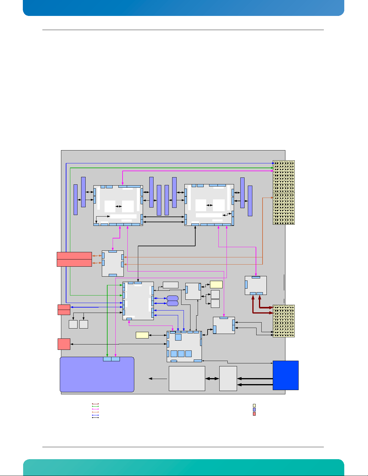
2.1 Block Diagram
Figure 2-1:Block Diagram
9 AT8060
Page 25

www.kontron.com
2.2 System Core
2.2.1 Processors (SandyBridge-EP Series)
• Built on 32 nanometer process technology.
• Six/Eight cores processor in 2011-land FCLGA.
• 32KB L1/core
• 256KB L2 / core
• Up to 20MB L3: Up to 2.5MB per core.
• Streaming SIMD Extension 4.1 and 4.2
• Integrated 4-channel DDR3 controller, DDR3-1600 memory with ECC
• Intel QuickPath interconnect links, 8.0/7.2 GT/s in each direction
• Intel 64 Bit Architecture
• Enhanced Intel SpeedStep Technology
• Intel Virtualization Technology (VT)
• Intel Hyper-Threading Technology (HT)
2.2.2 Intel Patsburg PCH
• Direct Media Interface (DMI) x4 lanes for communicating with CPU0
• SATA Gen3 up to 6Gbps, SAS Gen2 up to 3Gbps, USB
2.3 USB 2.0 Interfaces
The board embeds a USB controller in the PCH. This controller is compliant to USB 2.0. It provides two USB
ports on the face plate, two on the RTM and two ports are reserved for the eUSB SSD. Those ports can be used
for external storage and for booting.
USB supports Plug and Play and hot-swapping operations (OS level). These features allow USB devices to be
automatically attached, configured and detached, without reboot or running setup.
Signal Path:
- 2 USB 2.0 on front panel (J12, J13)
- 2 USB 2.0 on the RTM front panel
- 2 USB 2.0 onboard for the eUSB SSD
10 AT8060
Page 26
www.kontron.com
BIOS Settings:
Advanced -> USB Configuration
Chipset -> South Bridge -> USB Configuration
2.4 USB Flash Module
The AT8060 supports up to two Solid State Drives. It is a NAND flash disk module with a USB 2.0 interface. The
modules are socketed on two 2x5 headers attached to the AT8060. They are available in many sizes and
accessible only when removing the top cover. By default the USB devices are used as booting devices.
Signal Path:
USB Flash Module Connector are available on J10 and J11. See section 3.4 for more details.
BIOS Settings:
Advanced --> USB Configuration
Boot --> BBS
Note:
During the installation of an OS on a HDD, the USB Flash Module must be deactivated. If the USB
Flash Module remains active, the Master Boot Record will be installed on it by default. This can not
be avoided and will cause the OS to be unable to boot from the HDD.
2.5 Serial ATA/Serial Attached SCSI
2.5.1 Serial Attached SCSI
The PCH's SAS ports 0-3 are available in the RTM connector. It supports SATA GEN1 (1.5Gb/s), GEN2 (3Gb/s),
GEN3 (6Gb/s) and SAS 3Gb/s on the RTM storage interfaces.
2.5.2 Serial ATA (PCH)
The PCH SATA port 0 is connected to the AMC Port 2. It supports SATA GEN1 (1.5Gb/s), GEN2 (3Gb/s) and
GEN3 (6Gb/s) on the AMC storage interface.
11 AT8060
Page 27

www.kontron.com
2.6 Redundant BIOS Flash
Two redundant 64MBits, SPI EEPROMs are connected to PCH for the BIOS. Only one EEPROM at a time is
available for the PCH. If for some reason a BIOS update corrupts an EEPROM which prevents the CPU from
completing the boot sequence, the IPMC will swap the active SPI EEPROM and force a reboot.
2.7 Ethernet Interfaces
2.7.1 Fabric Interface
The fabric interface can be either 10GbE or 1GbE.
The AT8060 has boot from LAN capability (PXE) or iSCSI support on these ports. You can enable the option
from the BIOS Setup Program. Please refer to Section 5.1, AMI UEFI Setup Program.
The AT8060 has one dual port 10GbE controller (i82599EB) connected to the Fabric Interface. This controller
can also be used as a dual 1Gb. The controller auto-negociates between 10G-BASE-KX4 and 1G-BASE-KX.
Features high performance with TCP/IP and UDP/IP checksum offloading for IPv4 and IPv6, packet filtering,
and jumbo frame up to 15.5K.
See http://www.intel.com
Signal Path:
The two ports are available on the Fabric Interface.
BIOS Settings:
Advanced --> Legacy Expansion ROM Configuration -> FI: XE OpROM, Port 1 and 2
for additional details on the i82599EB.
2.7.2 Base Interface
An i82576EB dual port 1Gb Ethernet controller is connected on the Base Interface.
Boot from LAN capability (PXE) is supported on these ports. Enable the option from the BIOS Setup Program.
Please refer to Section 5.1, AMI UEFI Setup Program.
Features high performance with TCP/IP and UDP/IP checksum offloading for IPv4 and IPv6, packet filtering,
and jumbo frame up to 16K.
See http://www.intel.com
for additional details on the i82576EB.
12 AT8060
Page 28
www.kontron.com
Signal Path:
The two ports are available on the Base Interface.
BIOS Settings:
Advanced --> Legacy Expansion ROM Configuration -> BI: GE OpROM, Port 1 and 2
2.7.3 SFP
A Powerville quad 1000 Base-T / SerDes controller is installed onboard. Two ports are routed to the RTM and
two are routed to the front panel SFP connectors. The front SFP cages support multi-rate fiber SFP modules.
The SFP interfaces feature the following connectivity:
• front panel with a dual SFP cage
• two connections through the RTM connector
Signal Path:
The front panel and on the RTM.
BIOS Settings:
Advanced --> Legacy Expansion ROM Configuration -> FP: GE OpROM, Port 1 and 2 (front panel)->
RTM:
CAUTION LASER LIGHT!
Do not look into the laser beam!
The SFP module is fitted with a class 1 or 1M laser. To avoid possible exposure to
hazardous levels of invisible laser radiation, do not exceed maximum ratings.
The SFP port has a bi-color green/amber LED with the following signification:
Table 2-1: SFP LED Significations
LED Signification
Green on Link 1Gbit
Green blink Activity 1Gbit
Amber on Link 10/100Mbit
Amber blink Activity 10/100Mbit
13 AT8060
Page 29

www.kontron.com
2.8 Serial Interfaces
The AT8060 uses serial interfaces to manage the CPU, the only way to get visual information from the board
when used without a RTM806X. Serial ports are provided on the faceplate and on the RTM faceplate for
asynchronous serial communications. They are 16C550 high-speed UART compatible and support 16-byte
FIFO buffers for transfer rates from 9,6Kbps to 115,2Kbps.
Table 2-2:Serial Interface connector Pinout
Pin Signal
1 RTS
2 DTR
3 TX#
4 GND
5 GND
6 RX#
7 DSR
8 CTS
Note:
Standard product uses a RJ-45 8 pins connector. RI (ring indicator) and DCD (data carrier detect)
signals are not available.
The pinout is a custom one, not the same as RS-232D TIA/EIA-561.
Signal Path:
COM1 is routed to a RJ45 on the frontplate or to the IPMC for SOL.
COM2 is routed to the RTM serial interface.
BIOS Settings:
Advanced -> Serial Port Console Redirection -> Console Redirection Settings (COM0 and COM1)
2.9 AMC Mezzanine
The AMC slot supports AMC.1 (PCIe) and AMC.3 (SAS/SATA) in addition to the AMC.0 base specification. The
AMC is hot swappable according to PICMG 3.0 Rev. 2.0 and supports mid-size AMC units.
One AMC site is available. Characteristics of the AMC are as follow:
•Type B+
•Supports mid-size single width mechanical format
•PCI-Express X8 (GEN2 2.5GTs or 5.0GTs) with reference clock on AMC FCLKA
•Fully compliant PCI-Express hot plug support
14 AT8060
Page 30
www.kontron.com
•SATA link to the PCH
•Compliant to AMC.0, AMC.1 and AMC.3
•50W maximum power budget
Note:
The thermal solution needs to be validated by the integrator when AMC Thermal Design power
exceeds 20W.
As per AMC.1 R2.0, the carrier board is required to provide PCIe 100MHz reference clock to the AMC on FCLKA.
However, modules are not required to use it. Kontron recommends using AMC modules that use the reference
clock on FCLKA. If the module makes its own reference clock, then the spread spectrum of PCI-Express clock
synthetizer will be disabled by e-keying; otherwise the behavior of the PCI-Express link will be erratic.
Note:
All electromagnetic compatibility testing has been done with spread spectrum. Disabling the spread
spectrum can complicate EMC.
The SATA interface on port 2 allows to use a SATA AMC storage mezzanine on the AT8060. AMC SATA electrical
path is properly designed for Hot Swap operation but special care must be taken to ensure proper un-mount
sequence within the operating system.
BIOS Settings:
Advanced --> SATA Configuration
Advanced --> Legacy Expansion ROM Configuration -> AMC Slot OpROM(s)
Chipset -> IOH Configuration -> AMC Port Link Speed
Server Mgmt -> Managed FRU Deactivate Policies
Software Usage:
AMC serial port is available on port 15.
AMC serial port GUID : 471C5D14-2AE7-42B9-A9B0-0628546B42CC
Note:
The maximum power budget is 50W for an Advanced Mezzanine Card.
2.10 FPGA
The FPGA has many functions. One of them is to act as a companion chip to the IPMC. The states of all the
critical signals controlled by the IPMC are memorized in the FPGA and are preserved while the IPMC firmware
is being updated.
The FPGA is a RAM-based chip that is preloaded from a separate flash memory at power-up. Two such flash
memory devices are provided; one that can only be programmed in factory and the other one that can be
updated in the field. The factory flash is selected by inserting jumper JP2 pins 3-4. Field updates require to
cycle the power of the board. The IPMI LED2 will blink amber if the factory flash is being used to signal a fail
safe configuration.
The FPGA update complies to PICMG HPM.1 specification and is remotely updatable via any IPMC channel.
15 AT8060
Page 31

www.kontron.com
2.11 Redundant IPMC Firmware & BootBlock
The IPMC runs a firmware from SPI flash memory. The IPMC Boot Block saves the last two copies of the IPMC
firmware image in the same as it's boot block SPI flash memory. The Boot Block manages the IPMC
reprogrammation and can rollback to the previous firmware image in the IPMC internal flash in case of update
problem.
Note:
The IPMC has an external hardware watchdog.
2.12 LEDs Description
The following table lists the LED on the faceplate (excluding the SFP Ethernet LEDs).
Table 2-3:Faceplate LEDs
LED Name Color Controlled by Description
HDD activity Green Chipset/FPGA AMC & RTM HDD activity status
ATC A0 Blue IPMC Blade Hot Swap status
ATC A1 Amber/Red IPMC Blade OOS (out-of-service)
ATC A2 Amber/Green IPMC Healthy status
ATC A3 Amber/Green IPMC/CPU Application specific
B.I. 1 Amber/Green FPGA Base Interface Channel 1 Status
B.I. 2 Amber/Green FPGA Base Interface Channel 2 Status
F.I. 1 Amber/Green FPGA Fabric Interface Channel 1 Status
F.I. 2 Amber/Green FPGA Fabric Interface Channel 2 Status
RTM 1 Amber/Green FPGA
RTM 2 Amber/Green FPGA
FRONT 1 Amber/Green FPGA
FRONT 2 Amber/Green FPGA
Management LAN RTM Interface Channel
1 status
Management LAN RTM Interface Channel
2 status
Management LAN SFP Interface Channel
1 status
Management LAN SFP Interface Channel
2 status
2.12.1 Hot Swap LED (LED0)
The Blue / Hot Swap LED indicates the hot swap status of the unit. The LED is ON when it is safe to remove the
unit from the slot. During normal operation, this LED is OFF.
16 AT8060
Page 32

www.kontron.com
2.12.2 Out Of Service (LED1)
The AdvancedTCA LED1 is red or amber and indicates an Out-of-Service (OOS) condition. During normal
operation, the OOS LED is OFF. This LED is ON during firmware upgrade and is user configurable if needed by a
customer application.
2.12.3 Healthy LED (LED2)
The AdvancedTCA LED2 is green or amber and indicates a healthy condition. The healthy LED indicates if the
blade is powered up and all voltages and temperatures are within specifications. During normal operation,
this LED is ON (green). This LED is also ON (amber) when one of the RTM806X voltage or temperature fails.
17 AT8060
Page 33

www.kontron.com
Figure 2-2:Faceplate LEDs
Hot Swap (Blue)
Solid On (100 % on): FRU Inactive
Long Blink ( 90 % on): FRU Activation Request
Solid Off ( 0 % on): FRU Activation In Progress / FRU Active
Short Blink ( 10 % on): FRU Deactivation Request / FRU Deactivation In Progress
Out of service (Red/Amber) [ default : Red ]
Solid On : MMC in reset
Fast Blink (~50 % on) : MMC upgrade/rollback in progress
Application Defined : May be controlled by application using PICMG API
Health Led (Amber/Green) [ default : Green ]
Off : Payload power down
Green : Health Ok
Amber : Health Error (Critical)
Application Defined : May be controlled by application using PICMG API
Hard Disk Activity Led (Green)
Blink : Hard Disk Activity
FI Led (Green/Amber)
Green On : Link 10Gbit
Green Blink : Activity 10Gbit
Amber On : Link 1Gbit
Amber Blink : Activity 1Gbit
BI Led (Green/Amber)
Green On : Link 1Gbit
Green Blink : Activity 1Gbit
Amber On : Link 10-100Mbit
Amber Blink : Activity 10-100Mbit
SFP RTM Led (Green/Amber)
Green On : Link 1Gbit
Green Blink : Activity 1Gbit
Amber On : Link 10-100Mbit
Amber Blink : Activity 10-100Mbit
SFP Front Led (Green/Amber)
Green On : Link 1Gbit
Green Blink : Activity 1Gbit
Amber On : Link 10-100Mbit
Amber Blink : Activity 10-100Mbit
18 AT8060
Page 34

Chapter 3
Installing the Board
www.kontron.com
3.1 Setting Jumpers................................................ 20
3.2 Processor......................................................... 21
3.3 Memory........................................................... 21
3.4 Onboard Connectors and Headers ......................... 24
3.5 Board Hot Swap and Installation .......................... 25
Page 35

www.kontron.com
3. Installing the Board
3.1 Setting Jumpers
3.1.1 Jumper Description
Table 3-1:Jumper Description
Name Description Jumper
Reserved Reserved JP2 (1-2)
FPGA PROM Selection When On, it selects the factory prom JP2 (3-4)
Clear BIOS setup in flash When On, it clears the BIOS Setup JP2 (5-6)
Reserved Reserved JP2 (7-8)
Reserved Reserved JP2 (9-10)
Reserved Reserved JP2 (11-12)
Onboard video enable When On, it enables onboard video controller. JP2 (13-14)
Watchdogs When On, it disables the watchdogs JP1 (1-2)
Reserved Reserved JP1 (3-4)
Reserved Reserved JP1 (5-6)
AMC & RTM Activation When On, it overrides the AMC & RTM activation JP1 (7-8)
AMC PCIe Override When On, drives AMC/RTM PCIe clocks JP1 (9-10)
Reserved Reserved JP1 (11-12)
Reserved Reserved JP1 (13-14)
20 AT8060
Page 36

www.kontron.com
3.1.2 Jumper Setting & Locations
Watchdogs Disabled
Watchdogs Enabled
JP1 (1-2) Watchdogs
IN
OUT
Reserved
Normal
JP1 (3-4) Reserved
IN
OUT
Override (FPGA turn-on table)
Normal
JP1 (5-6) IPMI Override
IN
OUT
Override (turn-on FRUs)
Normal
JP1 (7-8) FRU Override
IN
OUT
Default Configuration
Override (drive FRUs clocks)
Normal
JP1 (9-10) FRU PCIe Override
IN
OUT
Factory Mode
Operation
JP1 (11-12) Factory Mode
IN
OUT
Reserved
Normal Normal Operation
JP1 (13-14) Reserved
IN
OUT
J1 J2 J3
J4 J5
J6
J7
J8
JP2
JP1
1
13
2
14
1
13
2
14
J30
J31
Reserved
Normal Operation
JP2 (1-2) Spare
IN
OUT
Factory Prom (Fail-Safe)
Normal (Auto)
JP2 (3-4) FPGA PROM Selection
IN
OUT
Reserved
Normal Operation
JP2 (5-6) Clear BIOS Setup In Flash
IN
OUT
Reserved
Normal Operation
JP2 (7-8) FPGA Reserved #0
IN
OUT
Reserved
Normal Operation
JP2 (9-10) FPGA Reserved #1
IN
OUT
Reserved
Normal Operation
JP2 (11-12) Reserved
IN
OUT
Reserved
Normal Operation
JP2 (13-14) IPMC Reserved
IN
OUT
Default Configuration
Figure 3-1:Jumper Settings and Locations
Note:
More details about the jumper settings can be found on the Quick Reference Sheet.
3.2 Processor
This product can be shipped with the CPUs and a thermal solution installed. The thermal solution is custom
and critical for passive cooling. Cooling performance can greatly be affected if heat sink is not handled
properly. Do not attempt any heat sink removal after installation.
3.3 Memory
The AT8060 has 4 memory channels connected to each CPU. There is one DIMM per memory channel for a total
of 4 per CPU. The AT8060 accepts DDR3, VLP(very low-profile) (0.72 inch; 18.29mm), 1.5V or 1.35V modules,
registered, ECC, x4 or x8 memory with up to 4 ranks per DIMM. The DDR3 memory channels run at 1333MHz or
1600MHz. The maximum DDR3 SDRAM size is 16GBytes per DIMM for a populated 128GBytes maximum.
Memory modules shall have a validated thermal solution (heatsink) and may necessitate a certain class of
chassis. It is recommended that modules have thermal sensors for accurate temperature monitoring and to
21 AT8060
Page 37

www.kontron.com
throttle the memory interface in case of overheating. Memory can perform double refresh rate to get higher
maximum operating temperature.
Kontron recommends the use of validated memory with this product. Thermal issues or other problems may
arise if you don’t use recommended modules. At the time of publication of this user guide, the following
memories memory list has been have been qualified and approved. As the memory market is volatile, this list
is subject to change, please consult your local technical support for an up to date list.
3.3.1 Memory List and Characteristics
Table 3-2:Approved Memory List
Manufacturer Part Number Description Company
M392B5273CH0-CK0 4GB VLP 1600 MHz RDIMM Samsung
M392B1K70CM0-CK0 8GB VLP 1600 MHz RDIMM Samsung
M392B5273CH0-YH904 8GB VLP 1333 MHz LV-RDIMM Samsung
VL33B5263E-K9S 4GB VLP 1333 MHz UDIMM Virtium
M392B2G70BM0-YK0 16GB VLP 1600 MHz RDIMM Samsung
SGU04G72H1BC2SA-BBRT 4GB VLP 1333 MHz UDIMM Swissbit
MT18JDF1G72PDZ-1G6 8GB VLP 1600 MHz RDIMM Micron
Memory should have the following characteristics:
• DDR3 1333 or DDR3 1600
• 1.35V or 1,5V
• Single or dual-rank modules are supported
• x4 or x8 memory with up to 4 ranks per DIMM
• Registered & ECC
• Only very low profiles (VLP) 0.72inches maximum heights (18.3mm)
WARNING
Because static electricity can cause damage to electronic devices, take the following
precautions:
Keep the board in its anti-static package, until you are ready to install memory.
Wear a grounding wrist strap before removing the board from its package; this will
discharge any static electricity that may have built up in your body.
Handle the board by the faceplate or its edges.
22 AT8060
Page 38

www.kontron.com
3.3.2 Installing Memory
On an anti-
static plane, place the board so that you
are facing the front plate connectors
Remove the memory protection top cover.
Insert the memory module into any available
socket, aligning the notches on the module with the
socket’s key inserts.
1- Insert the memory module in the connector
using
your thumbs.
2- Eject partially the memory module, using the
connector latches while applying some pressure on
the top to avoid the full removal of the modules.
3- Fully Reseat the modules in the connector
using
your thumbs.
4- Repeat steps 2 and 3 a second time.
5- Push down the memory module until the
retaining clips lock on each side.
Repeat these steps to populate the other socket.
To remove a memory module from a socket, push
sideway the retaining clips on each side of the
socket, to release the module. Pull out the memory
from the socket.
23 AT8060
Page 39

www.kontron.com
3.4 Onboard Connectors and Headers
P10
J1 J2 J3
J4 J5
J6
J7
J8
J10 J11
J12
J13
J15
J17
J19
JP2
JP1
1
13
2
14
1
13
2
14
J30
J31
J23
A
B
C
D
G
H
E
F
Table 3-3:Onboard Connectors and Headers
Description Connector Comments
Memory Sockets J1 -J8 DDR3 1333MHz or DDR3 1600 MHz Memory Sockets
USB Flash Connectors J10 & J11 USB Connectors for the USB SSD Modules
USB Connectors J12 Dual USB Connector
Management Console Port J13 RJ-45 Serial Port Connector
SFP Connectors J15 & J17 Faceplate SFP Connectors
AMC connector J19 AMC Connector
Base & Fabric Interface Connector J23 Base & Fabric Interface Connector
RTM Connectors J30 & J31 RTM Connectors
Power & IPMB P10 Power & IPMB
Figure 3-2:Onboard Connectors and Headers Locations
24 AT8060
Page 40

www.kontron.com
3.5 Board Hot Swap and Installation
Because of the high-density pinout of the hard-metric connector, some precautions must be taken when
connecting or disconnecting a board to/from a backplane:
1 Rail guides must be installed on the enclosure to slide the board to the backplane.
2 Do not force the board if there is mechanical resistance while inserting the board.
3 Screw the frontplate to the enclosure to firmly attach the board to its enclosure.
4 Use ejector handles to disconnect and extract the board from its enclosure.
WARNING
Always use a grounding wrist wrap before installing or removing the board from a
chassis.
3.5.1 Installing the Board in the Chassis
To install a board in a chassis:
1 Remove the filler panel of the slot or see "Removing the Board" below.
2 Ensure the board is configured properly.
3 Carefully align the PCB edges in the bottom and top card guide.
4 Insert the board in the system until it makes contact with the backplane connectors.
5 Using both ejector handles, engage the board in the backplane connectors until both ejectors are locked.
6 Fasten screws at the top and bottom of the faceplate.
3.5.2 Removing the Board
If you would like to remove a card from your chassis please follow carefully these steps:
1 Unscrew the top and the bottom screw of the front panel.
2 Unlock the lower handle latch, depending on the software step; this may initiate a clean shutdown of the
operating system.
3 Wait until the blue LED is fully ON, this mean that the hot swap sequence is ready for board removal.
4 Use both ejectors to disengage the board from the backplane.
5 Pull the board out of the chassis.
25 AT8060
Page 41

www.kontron.com
3.5.3 Installing an AMC
To install an AMC:
1 Remove the AMC filler panel.
2 Carefully engage the AMC into the card guide. Push the AMC until it fully mates with its connector. Secure
the AMC handle to the locking position.
3 In normal condition, the blue LED shall turn ON as soon as the AMC is fully inserted. It will turn OFF at the
end of the hot swap sequence.
3.5.4 Removing an AMC
To remove an AMC:
1 Pull out the handle to unlock the AMC.
2 Wait for the blue LED to turn on continuously.
3 Pull out the AMC using the handle.
3.5.5 Installing the (RTM806X or RTM8050)
To install the RTM:
1 Remove the filler panel of the slot.
2 Ensure the board is configured properly.
3 Carefully align the PCB edges in the bottom and top card guide.
4 Insert the board in the system until it makes contact with the CPU board.
5 Using both ejector handles, engage the board in the CPU board connectors until both ejectors are locked.
6 Fasten screws at the top and bottom of the faceplate.
3.5.6 Removing the (RTM806X or RTM8050)
To remove the RTM:
1 Unscrew the top and the bottom screw of the faceplate.
2 Unlock the lower handle latch.
3 Wait until the blue LED is fully ON, this mean that the hot swap sequence is ready for board removal.
4 Use both ejectors to disengage the board from the CPU board.
5 Pull the board out of the chassis.
26 AT8060
Page 42

Chapter 4
Management
www.kontron.com
4.1 Hardware Management Overview .......................... 28
4.2 Configuring LAN interface ................................... 28
4.3 Web Management Interface................................. 28
4.4 Hardware Management Functionality .................... 31
4.5 IPMC Specific Features........................................ 31
4.6 IPMC............................................................... 33
Page 43

www.kontron.com
4. Management
4.1 Hardware Management Overview
The purpose of the hardware management system is to monitor, control, ensure proper operation and
provide hot swap support of ATCA Boards. The hardware management system watches over the basic health of
the system, reports anomalies, and takes corrective action when needed. The hardware management system
can retrieve inventory information and sensor readings as well as receive event reports and failure
notifications from boards and other Intelligent FRUs. The hardware management system can also perform
basic recovery operations such as power cycle or reset of managed entities.
4.2 Configuring LAN interface
Before connecting to the Management Interface, the Management IP address needs to be confirmed. To
obtain the address or configure it:
• Enter the BIOS Setup.
• Go to Set BMC network configuration menu, which is located under “Server Mgmt”.
• Choose the LAN channel to be configured.
• Select state and IP source (static or dynamic).
• When selecting IP source static, select IP Address, Subnet Mask and Gateway Address.
• Set LAN channel IP Address source, IP Address, Subnet Mask and if required, the Gateway address on the
corresponding menu.
4.3 Web Management Interface
4.3.1 Connecting to the Web Management Interface
To have access to the Web Management Interface, at least one of the IPMC LAN interfaces must be configured
and accessible over the Base interface.
To access the Web Management Interface:
• From a remote system, open a web browser.
• Type the IP address of the management controller in the browser.
• Default username and password are admin / admin.
Note:
A maximum of 4 sessions can be opened simultaneously. Up to 5 users can be configured. An
automatic logout will be done after 5 minutes of inactivity.
28 AT8060
Page 44

www.kontron.com
4.3.2 System
4.3.2.1 System Information
Once connected to the Web Management Interface, the first page displayed is the System Information. The
current component versions and board information such as serial numbers and part numbers are displayed
on this page
4.3.2.2 LAN Info
This page displays information on the IPMC LAN interfaces configuration. This configuration can be updated
using this interface.
Note:
Configuration of the LAN interface being in use to access the Web Management Interface may lead
to loss of connection.
4.3.2.3 System Tree
This page list the IPMB addresses of the boards connected in the chassis.
4.3.3 Sensor
4.3.3.1 Reading
This page displays all board sensor readings. Values can be manually refreshed. Refer to Table 4-20 for a list
of sensors for this board.
4.3.4 Event Log
4.3.4.1 Reading
This page displays System Event Log (SEL) information and the event list. The SEL can have up to 5119
entries, and it can be cleared or refreshed manually. Using the arrows under the table allows browsing
through the event list.
4.3.5 Control
4.3.5.1 Remote Power / Reset
This page displays the current Hot-Swap state, Power state and power level of the board and its managed
FRUs. It also allows performing power down, graceful shutdown, power cycle, power up and reset of all the
FRUs.
Note:
Power up of FRU0 is not supported, as the Web Management Interface is not accessible when it is
powered down.
29 AT8060
Page 45

www.kontron.com
4.3.6 Maintenance
4.3.6.1 Component Info
This page displays HPM Upgrade information and current component versions.
4.3.6.2 Component Upgrade
This page allows upgrading the FPGA and / or the IPMI firmware from the Web Management Interface using a
HPM file. To proceed, here are the steps to follow:
• Click “Browse…” and select the HPM file to upload. Then, click on “File Upload”.
• When the file is uploaded, information on the HPM file is displayed. At this point, it is possible to select
the component to upgrade if the file covers more than one component.
• Start the firmware upgrade by clicking “Start Upgrade Component(s)”. A progress bar will display the
upgrade status for each component.
• If the upgrade is successful, the “Activate and Reboot Management” button will be displayed. Click on it to
activate the new firmware.
4.3.6.3 Documentation
This page give you access to the product "Quick Reference Sheet". Use the download button to save a copy of
the PDF document.
4.3.6.4 Users
This page is used to manage the authorized users. A maximum of five (5) users can be set. All users can be
enabled or disabled. Privilege levels are defined in the table below.
Table 4-1: Privilege Level Description
Privilege Levels Description
Administrator
Operator
User
Callback
No Access No access is given to this user.
The User ID 1 is a user without name and password. This user can be enabled or disabled and has a privilege
level set to “User” by default.
All BMC commands are allowed, including configuration settings. An Administrator can even execute
configuration commands that would disable the channel that the Administrator is working on.
All BMC commands are allowed, except for configuration settings which can change the behavior of the
out-of-band interfaces. For example, Operator privilege does not allow the capability to disable
individual channels, or change user access privileges.
Only “basic” commands are allowed. These are primarily commands that read data and retrieve status.
Commands that can be used to alter BMC configuration, write data to the management controllers, or
perform system actions such as resets, power on/off, and watchdog activation are locked.
This may be considered the lowest privilege level. Only commands necessary to support initiating a
callback are allowed.
The User ID2 is pre-configured like an admin user. It has the “Administrator” privileges.
30 AT8060
Page 46

www.kontron.com
The User ID3 to User ID5 are configurable. By default they are not set to “Enable”.
4.3.7 Logout
This button allows a safe logout of the management interface.
An automatic logout will be done after 5 minutes of inactivity.
4.4 Hardware Management Functionality
The Front Blade Unit supports an “intelligent” hardware management system, based on the Intelligent
Platform Management Interface Specification. The hardware management system of the Front Blade Unit
provides the ability to manage the power and interconnect needs of intelligent devices, to monitor events,
and to log events to a central repository.
4.5 IPMC Specific Features
4.5.0.1 IPMC - Interface
The principal management-oriented link within a Shelf is a two-way redundant implementation of the
Intelligent Platform Management Bus (IPMB). IPMB is based on the inter-integrated circuit (I2C) bus and is
part of the IPMI architecture. In AdvancedTCA Shelves, the main IPMB is called IPMB-0. Each entity attached
to IPMB-0 does so through an IPM Controller, the distributed management controller of the IPMI
architecture. Shelf Managers attach to IPMB-0 through a variant IPM Controller called the Shelf Management
Controller (ShMC). AdvancedTCA IPM Controllers, besides supporting dual redundant IPMBs, also have
responsibility for detecting and recovering from IPMB faults.
The reliability of the AdvancedTCA IPMB-0 is increased by using two IPMBs, with the two IPMBs referenced as
IPMB-A and IPMB-B. The aggregation of the two IPMBs is IPMB-0. The IPM Controllers aggregate the
information received on both IPMBs. An IPM Controller that has a message ready for transmit uses the IPMBs
in a round robin fashion. An IPM Controller tries to alternate the transmission of messages between IPMB-A
and IPMB-B.
If an IPM Controller is unable to transmit on the desired IPMB then it tries to send the message on the
alternate IPMB. By using this approach, an IPMB can become unavailable and then available without the IPM
Controller needing to take specific action.
4.5.0.2 IPMC - System Manager Interface
The Section 24 of [IPMI 2.0] describes how IPMI messages can be sent to and from the IPMC encapsulated in
RMCP (Remote Management Control Protocol) packets datagrams. This capability is also referred to as “IPMI
over LAN” (IOL). IPMI also defines the associated LAN-specific configuration interfaces for setting things
such as IP addresses and other options, as well as commands for discovering IPMI-based systems. The
Distributed Management Task Force (DMTF) specifies the RMCP format. This LAN communication path makes
the Front Blade Unit reachable to the System Manager for any management action (IPMC firmware upgrade,
query of all FRU Data, CPU reset etc.) without the need to go through the ShMC.
31 AT8060
Page 47

www.kontron.com
4.5.0.3 IPMC - System Event Log
The Kontron IPMC implementation includes a Local System Event Log device as specified in the Section 31 of
[IPMI 2.0]. The local System Event Log is a nonvolatile repository for the front board and all managed FRU
events (AMC/RTM). The local SEL provides space for more than 5000 entries. However, even if blade events
are logged into the local SEL, the IPMI platform event messages are still generated by the IPMC's Event
Generator and sent to the centralized SEL hosted by the Shelf Manager through the IPMB-0 communication
path - [PICMG 3.0] chapter 3.5; [IPMI 2.0] Section 29. Local SEL is useful for maintenance purposes and
provides access to the events when the FRU is extracted from the Shelf.
4.5.1 Sensors
For more details about onboard sensors consult the application note: Product Sensor User Guide. This
application note is available from the Kontron web site at: www.kontron.com
32 AT8060
Page 48

www.kontron.com
4.6 IPMC
4.6.1 Supported Commands
The table below lists the IPMI commands supported by the IPMC. This table is identical as the one provided by
AMC.0 and PICMG 3.0. The last column states the Kontron support for the specific command.
Table 4-2:IPM Device Supported Commands for IPMC
IPMI Spec. section NetFn CMD IPMI BMC req. Carrier IPMC req. Kontron support
on IPMC
IPM Device “Global”
Commands
Get Device ID 20.1 App 01h M M Yes
Cold Reset 20.2 App 02h O O Ye s
Warm Reset 20.3 App 03h O O No
Get Self Test Results 20.4 App 04h M M Ye s
Manufacturing Test On 20.5 App 05h O O Ye s
Set ACPI Power State 20.6 App 06h O O Yes
Get ACPI Power State 20.7 App 07h O O Ye s
Get Device GUID 20.8 App 08h O O Yes
M M
Table 4-3:Watchdog Timer Supported Commands for IPMC
IPMI Spec. section NetFn CMD IPMI BMC req. Carrier IPMC
req.
BMC Watchdog Timer
Commands
Reset Watchdog Timer 27.5 App 22h M M Yes
Set Watchdog Timer 27.6 App 24h M M Yes
Get Watchdog Timer 27.7 App 25h M M Yes
M M
Table 4-4:Device Messaging Supported Commands for IPMC
IPMI Spec. section NetFn CMD IPMI BMC req. Carrier IPMC
req.
BMC Device and
Messaging
Commands[5]
Set BMC Global Enables 22.1 App 2Eh M O/M Yes
Get BMC Global Enables 22.2 App 2Fh M O/M Ye s
Clear Message Flags 22.3 App 30h M O/M Yes
Get Message Flags 224 App 31h M O/M Yes
M O
Kontron support
on IPMC
Kontron support
on IPMC
33 AT8060
Page 49

www.kontron.com
IPMI Spec. section NetFn CMD IPMI BMC req. Carrier IPMC
req.
Enable Message Channel
Receive
Get Message 22.6 App 33h M O/M Yes
Send Message 22.7 App 34h M M Yes
Read Event Message
Buffer
Get BT Interface
Capabilities
Get System GUID 22.14 App 37h O O Ye s
Get Channel
Authentication
Capabilities
Get Session Challenge 22.15 App 39h O O Ye s
Activate Session 22.17 App 3Ah O O Ye s
Set Session Privilege
Level
Close Session 22.19 App 3Ch O O Ye s
Get Session Info 22.20 App 3Dh O O Yes
Get AuthCode 22.21 App 3Fh O O No
Set Channel Access 22.22 App 40h O O Ye s
Get Channel Access 22.23 App 41h O O Ye s
Get Channel Info 22.24 App 42h O O Ye s
Set User Access 22.26 App 43h O O Yes
Get User Access 22.27 App 44h O O Yes
Set User Name 22.28 App 45h O O Yes
Get User Name 22.29 App 46h O O Yes
Set User Password 22.30 App 47h O O Yes
Activate Payload 24.1 App 48h Yes
Deactivate Payload 24.2 App 49h Yes
Get Payload Activation
Status
Get Payload Instance
Info
Set User Payload Access 24.6 App 4Ch Ye s
Get User Payload Access 24.7 App 4Dh Yes
Get Channel Payload
Support
Get Channel Payload
Version
Get Channel OEM
Payload Info
Master Write-Read 22.11 App 52h Yes
22.5 App 32h O O Ye s
22.8 App 35h O O Ye s
22.10 App 36h M O/M No
22.13 App 38h O O Yes
22.18 App 3Bh O O Ye s
24.4 App 4Ah Yes
24.5 App 4Bh Yes
24.8 App 4Eh Yes
24.9 App 4Fh Yes
24.10 App 50h No
Kontron support
on IPMC
34 AT8060
Page 50

www.kontron.com
IPMI Spec. section NetFn CMD IPMI BMC req. Carrier IPMC
Get Channel Cipher
Suites
Suspend/Resume
Payload Encryption
Set Channel Security
Keys
Get System Interface
Capabilities
22.15 App 54h Ye s
24.3 App 55h Ye s
22.25 App 56h Ye s
22.9 App 57h Yes
Table 4-5:Chassis Device Supported Commands for IPMC
req.
Kontron support
on IPMC
IPMI Spec. section NetFn CMD IPMI BMC req. Carrier IPMC
req.
Chassis Device
Commands
Get Chassis Capabilities 28.1 Chassis 00h M O Ye s
Get Chassis Status 28.2 Chassis 01h O/M O Yes
Chassis Control 28.3 Chassis 02h O/M O Yes
Chassis Reset 28.4 Chassis 03h O O No
Chassis Identify 28.5 Chassis 04h O O No
Set Chassis Capabilities 28.7 Chassis 05h O O No
Set Power Restore Policy 28.8 Chassis 06h O O No
Get System Restart
Cause
Set System Boot Options 28.12 Chassis 08h No
Get System Boot Options 28.13 Chassis 09h No
Get POH Counter 22.12 Chassis 0Fh O O No
28.11 Chassis 07h O O No
O O
Table 4-6:Event Supported Commands for IPMC
IPMI Spec. section NetFn CMD IPMI BMC req. Carrier IPMC
req.
Event Commands M M
Set Event Receiver 29.1 S/E 01h M M Yes
Get Event Receiver 29.2 S/E 02h M M Yes
Platform Event 29.3 S/E 03h M M Yes
Kontron support
on IPMC
Kontron support
on IPMC
35 AT8060
Page 51

www.kontron.com
Table 4-7:PEF and Alerting Supported Commands for IPMC
IPMI Spec. section NetFn CMD IPMI BMC req. Carrier IPMC
req.
PEF and Alerting
Commands
Get PEF Capabilities 30.1 S/E 10h M M Ye s
Arm PEF Postpone Timer 30.2 S/E 11 h M M Ye s
Set PEF Configuration
Parameters
Get PEF Configuration
Parameters
Set Last Processed Event
ID
Get Last Processed Event
ID
Alert Immediate 30.7 S/E 16h O O No
PET Acknowledge 30.8 S/E 17h O O No
30.3 S/E 12h M M Ye s
30.4 S/E 13h M M Ye s
30.5 S/E 14h M M Yes
30.6 S/E 15h M M Ye s
O O
Table 4-8:Sensor Device Supported Commands for IPMC
IPMI Spec. section NetFn CMD IPMI BMC req. Carrier IPMC
req.
Sensor Device
Commands
Get Device SDR Info 35.2 S/E 20h O M Yes
Get Device SDR 35.3 S/E 21h O M Ye s
Reserve Device SDR
Repository
Get Sensor Reading
Factors
Set Sensor Hysteresis 35.6 S/E 24 h O O Ye s
Get Sensor Hysteresis 35.7 S/E 25h O O Yes
Set Sensor Threshold 35.8 S/E 26h O O Ye s
Get Sensor Threshold 35.9 S/E 27h O O Yes
Set Sensor Event Enable 35.10 S/E 28h O O Ye s
Get Sensor Event Enable 35.11 S/E 29h O O Ye s
Re-arm Sensor Events 35.12 S/E 2Ah O O No
Get Sensor Event Status 35.13 S/E 2Bh O O No
Get Sensor Reading 35.14 S/E 2Dh M M Ye s
Set Sensor Type 35.15 S/E 2Eh O O No
Get Sensor Type 35.16 S/E 2Fh O O No
35.4 S/E 22h O M Yes
35.5 S/E 23h O M No
O M
Kontron support
on IPMC
Kontron support
on IPMC
36 AT8060
Page 52

www.kontron.com
Table 4-9:FRU Device Supported Commands for IPMC
IPMI Spec. section NetFn CMD IPMI BMC req. Carrier IPMC
req.
FRU Device Commands M M
Get FRU Inventory Area
Info
Read FRU Data 34.2 Storage 11h M M Yes
Write FRU Data 34.3 Storage 12h M M Ye s
34.1 Storage 10h M M Yes
Table 4-10:SDR Device Supported Commands for IPMC
IPMI Spec. section NetFn CMD IPMI BMC req. Carrier IPMC
req.
SDR Device Commands M O
Get SDR Repository Info 33.9 Storage 20h M M No
Get SDR Repository
Allocation Info
Reserve SDR Repository 33.11 Storage 22h M M No
Get SDR 33.12 Storage 23h M M No
Add SDR 33.13 Storage 24h M O/M No
Partial Add SDR 33.14 Storage 25h M O/M No
Delete SDR 33.15 Storage 26h O O No
Clear SDR Repository 33.16 Storage 27h M O/M No
Get SDR Repository Time 33.17 Storage 28h O/M O/M No
Set SDR Repository Time 33.18 Storage 29h O/M O/M No
Enter SDR Repository
Update Mode
Exit SDR Repository
Update Mode
Run Initialization Agent 33.21 Storage 2Ch O O No
33.10 Storage 21h O O No
33.19 Storage 2Ah O O No
33.20 Storage 2Bh M M No
Kontron support
on IPMC
Kontron support
on IPMC
Table 4-11:SEL Device Supported Commands for IPMC
IPMI Spec. section NetFn CMD IPMI BMC req. Carrier IPMC
req.
SEL Device Commands M O
Get SEL Info 31.2 Storage 40h M M Yes
Get SEL Allocation Info 31.3 Storage 41h O O Ye s
Reserve SEL 31.4 Storage 42h O O Yes
Get SEL Entry 31.5 Storage 43h M M Ye s
Add SEL Entry 31. 6 Storage 44h M M Yes
Partial Add SEL Entry 31.7 Storage 45h M M No
Delete SEL Entry 31.8 Storage 46h O O Ye s
37 AT8060
Kontron support
on IPMC
Page 53

www.kontron.com
IPMI Spec. section NetFn CMD IPMI BMC req. Carrier IPMC
req.
Clear SEL 31.9 Storage 47h M M Yes
Get SEL Time 31.10 Storage 48h M M Yes
Set SEL Time 31.11 Storage 49h M M Yes
Get Auxiliary Log Status 31.12 Storage 5Ah O O No
Set Auxiliary Log Status 31.13 Storage 5Bh O O No
Table 4-12:LAN Device Supported Commands for IPMC
Kontron support
on IPMC
IPMI Spec. section NetFn CMD IPMI BMC req. Carrier IPMC
req.
LAN Device Commands O O
Set LAN Configuration
Parameters
Get LAN Configuration
Parameters
Suspend BMC ARPs 23.3 Tran spo rt 03h O/M O/M Ye s
Get IP/UDP/RMCP
Statistics
23.1 Tr ans por t 01h O/M O/M Ye s
23.2 Tr ans por t 02h O/M O/M Ye s
23.4 Tr ans por t 04h O O Ye s
Table 4-13:Serial/Modem Device Supported Commands for IPMC
IPMI Spec. section NetFn CMD IPMI BMC req. Carrier IPMC
req.
Serial/Modem Device
Commands
Set Serial/Modem
Configuration
Get Serial/Modem
Configuration
Set Serial/Modem Mux 25.3 Tr ans por t 12h O O No
Get TAP Response Codes 25.4 Tr ansp or t 13h O O No
Set PPP UDP Proxy
Transmit Dat a
Get PPP UDP Proxy
Transmit Dat a
Send PPP UDP Proxy
Packet
Get PPP UDP Proxy
Receive Data
25.1 Tr ans por t 10h O/M O/M No
25.2 Tr ans por t 11 h O/M O/M No
25.5 Tr ans por t 14h O O No
25.6 Tr ans por t 15h O O No
25.7 Tr ans por t 16h O O No
25.8 Tr ans por t 17h O O No
O O
Kontron support on
IPMC
Kontron support on
IPMC
38 AT8060
Page 54

www.kontron.com
IPMI Spec. section NetFn CMD IPMI BMC req. Carrier IPMC
req.
Serial/Modem
Connection Active
Callback 25.10 Tr ansport 19h O O No
Set User Callback
Options
Get User Callback
Options
25.9 Tr ans por t 18h O/M O/M No
25.11 Tr ansp or t 1Ah O O No
25.12 Tr ansport 1Bh O O No
Table 4-14:SOL Commands
Kontron support on
IPMC
IPMI Spec. section NetFn CMD IPMI BMC req. Carrier IPMC
req.
SOL Commands O O
SOL Activating 26.1 Tra nsp ort 20h No
Set SOL Configuration
Params
Get SOL Configuration
Params
26.2 Tra nsp ort 21h Ye s
26.3 Tra nsp ort 22h Yes
Table 4-15:PICMG 3.0 Commands for IPMC
IPMI Spec. section NetFn CMD IPMI BMC req. Carrier IPMC
req.
AdvancedTCA® PICMG® 3.0 Table M
Get PICMG Properties 3-11 PICMG 00h M Yes
Get Address Info 3-10 PICMG 01h M Yes
Get Shelf Address Info 3-16 PICMG 02h O Ye s
Set Shelf Address Info 3-17 PICMG 03h O No
FRU Control 3-27 PICMG 04h M Ye s
Get FRU LED Properties 3-29 PICMG 05h M Ye s
Get LED Color
Capabilities
Set FRU LED State 3-31 PICMG 07h M Ye s
Get FRU LED State 3-32 PICMG 08h M Ye s
Set IPMB State 3-70 PICMG 09h M Yes
Set FRU Activation Policy 3-20 PICMG 0Ah M Yes
Get FRU Activation Policy 3-21 PICMG 0Bh M Yes
Set FRU Activation 3-19 PICMG 0Ch M Ye s
Get Device Locator
Record ID
Set Port State 3-59 PICMG 0Eh O/M Ye s
Get Port State 3-60 PICMG 0Fh O/M Ye s
3-30 PICMG 06h M Ye s
3-39 PICMG 0Dh M Ye s
Kontron support on
IPMC
Kontron support on
IPMC
39 AT8060
Page 55

www.kontron.com
IPMI Spec. section NetFn CMD IPMI BMC req. Carrier IPMC
req.
Compute Power
Properties
Set Power Level 3-84 PICMG 11h M Ye s
Get Power Level 3-83 PICMG 12h M Yes
Renegotiate Power 3-91 PICMG 13h O No
Get Fan Speed Properties 3-86 PICMG 14h O/M No
Set Fan Level 3-88 PICMG 15h O/M No
Get Fan Level 3-87 PICMG 16h O/M No
Bused Resource 3-62 PICMG 17h O/M Yes
Get IPMB Link Info 3-68 PICMG 18h O/M Yes
Get Shelf Manager IPMB
Address
Set Fan Policy 3-89 PICMG 1Ch M No
Get Fan Policy 3-90 PICMG 1Dh M No
FRU Control Capabilities 3-29 PICMG 1Eh M Ye s
FRU Inventory Device
Lock Control
FRU Inventory Device
Write
Get Shelf Manager IP
Addresses
Get Shelf Power
Allocation
Get Telco Alarm
Capability
Set Telco Alarm State 3-94 PICMG 2Ah O/M No
Get Telco Alarm State 3-95 PICMG 2Bh O/M No
Get Telco Alarm Location 3-95 PICMG 39h O/M No
Set FRU Extracted 3-25 PICMG 3Ah M No
3-82 PICMG 10h M Yes
3-38 PICMG 1Bh M No
3-42 PICMG 1Fh M No
3-43 PICMG 20h M No
3-36 PICMG 21h M No
3-85 PICMG 22h M No
3-93 PICMG 29h O/M No
Kontron support on
IPMC
Table 4-16:AMC.0 Carrier Commands for IPMC
IPMI Spec. section NetFn CMD IPMI BMC req. Carrier IPMC
req.
AMC AMC.0 Table
Set AMC Port State Table 3-27 PICMG 19h O/M Yes
Get AMC Port State Table 3-28 PICMG 1Ah O/M Ye s
Set Clock State Table 3-44 PICMG 2Ch O/M Yes
Get Clock State Table 3-45 PICMG 2Dh O/M Ye s
40 AT8060
Kontron support on
IPMC
Page 56

www.kontron.com
Table 4-17:HPM Commands
IPMI Spec. section NetFn CMD IPMI BMC req. Carrier IPMC
req.
HPM
Get Target Upgrade
Capabilities
Get Component
Properties
Abort Firmware Upgrade Yes
Initiate Upgrade Action Yes
Upload Firmware Block Yes
Finish Firmware Upload Yes
Get Upgrade Status Yes
Activate Firmware Yes
Query Self-Test Results Ye s
Query Rollback Status Yes
Initiate Manual Rollback Yes
Kontron support on
IPMC
Yes
Yes
4.6.2 Sensor Data Records
Information that describes the IPMC capabilities is provided through two mechanisms: capabilities
commands and Sensor Data Records (SDRs). Capabilities commands are commands within the IPMI command
set that return fields providing information on other commands and functions the controller can handle.
Sensor Data Records are data records containing information about the type and number of sensors in the
platform, sensor threshold support, event generation capabilities, and information on what types of
readings the sensor provides. The primary purpose of Sensor Data Records is to describe the sensor
configuration of the hardware management subsystem to system software.
The IPMC are required to maintain Device Sensor Data Records for the sensors and objects they manage.
Access methods for the Device SDR entries are described in the [IPMI 2.0] specification, Section 35, "Sensor
Device Commands."
After a FRU is inserted, the System Manager, using the Shelf Manager, may gather the various SDRs from the
FRU's IPM Controller to learn the various objects and how to use them. The System Manager uses the "Sensor
Device Commands" to gather this information. Thus, commands, such as "Get Device SDR Info" and "Get
Device SDR," which are optional in the IPMI specification, are mandatory in AdvancedTCA systems.
Most of the current Shelf Manager implementation gathers the individual Device Sensor Data Records of each
FRU into a centralized SDR Repository. This SDR Repository may exist in either the Shelf Manager or System
Manager. If the Shelf Manager implements the SDR Repository on-board, it shall also respond to "SDR
Repository" commands.
This duplication of SDR repository commands creates sometime some confusion among AdvancedTCA users.
This is mandatory for IPMC to support the Sensor Device Commands for IPMC built-in SDR as described in the
[IPMI 2.0] specification, Section 35, "Sensor Device Commands." For the ShMC, the same set of commands
for the centralized SDR Repository must be supported but they are described in the [IPMI 2.0] specification,
Section 33, "SDR Repository Commands."
41 AT8060
Page 57

www.kontron.com
4.6.2.1 IPMC Sensors
Table 4-18: IPMC Sensors
0 FRU0 Hot Swap Discrete
1 FRU1 Hot Swap Discrete
2 FRU2 Hot Swap Discrete
ATCA Board FRU Hot Swap Sensor for FRU 0 (Front Board)
Sensor type code = F0h PICMG Hot Swap
Event Reading type code = 6Fh Sensor specific
See PICMG 3.0 R3.0 Table 3-22, “FRU Hot Swap event message”
ATCA Board FRU Hot Swap Sensor for FRU 1 (AMC B1)
Available only when AMC is inserted
Sensor type code = F0h PICMG Hot Swap
Event Reading type code = 6Fh Sensor specific
See PICMG 3.0 R3.0 Table 3-22, “FRU Hot Swap event message”
ATCA Board FRU Hot Swap Sensor for FRU 2 (RTM)
Available only when RTM is inserted
Sensor type code = F0h PICMG Hot Swap
Event Reading type code = 6Fh Sensor specific
See PICMG 3.0 R3.0 Table 3-22, “FRU Hot Swap event message”
3 FRU3 Hot Swap Discrete
4 FRU4 Hot Swap Discrete
5 FRU0 Reconfig Discrete
6 Temp Board Inlet Threshold
ATCA Board FRU Hot Swap Sensor for FRU 3 (RTM Disk 1)
Available only when RTM and 1 disk is inserted
Sensor type code = F0h PICMG Hot Swap
Event Reading type code = 6Fh Sensor specific
See PICMG 3.0 R3.0 Table 3-22, “FRU Hot Swap event message”
ATCA Board FRU Hot Swap Sensor for FRU 4 (RTM Disk 2)
Available only when RTM and 2 disks are inserted
Sensor type code = F0h PICMG Hot Swap
Event Reading type code = 6Fh Sensor specific
See PICMG 3.0 R3.0 Table 3-22, “FRU Hot Swap event message”
Sensor Population Change on Carrier
Sensor type = 12h System Event
Event Reading type code = 6Fh Sensor specific, only offset 0 is
used
See AMC.0 R2.0 for event trigger
See IPMI v2.0 table 42-3, Sensor type code 12h for sensor
definition
Board Inlet Temperature (Degrees)
Sensor type = 01h temperature
Event Reading type code = 01h threshold based
See IPMI v2.0 table 42-2 for threshold based event
42 AT8060
Page 58

www.kontron.com
7 Temp AMC Outake Threshold
8 Temp CPU0 Threshold
9 Temp CPU1 Threshold
10 Temp Vcore0 Threshold
11 Temp Vcore1 Threshold
AMC Outake Temperature (Degrees)
Sensor type = 01h temperature
Event Reading type code = 01h threshold based
See IPMI v2.0 table 42-2 for threshold based event
CPU0 Temperature (Degrees)
Sensor type = 01h temperature
Event Reading type code = 01h threshold based
See IPMI v2.0 table 42-2 for threshold based event
CPU1 Temperature (Degrees)
Sensor type = 01h temperature
Event Reading type code = 01h threshold based
See IPMI v2.0 table 42-2 for threshold based event
CPU0 Vcore Switcher Temperature (Degrees)
Sensor type = 01h temperature
Event Reading type code = 01h threshold based
See IPMI v2.0 table 42-2 for threshold based event
CPU1 Vcore Switcher Temperature (Degrees)
Sensor type = 01h temperature
Event Reading type code = 01h threshold based
See IPMI v2.0 table 42-2 for threshold based event
12 Temp DIMM A Threshold
13 Temp DIMM B Threshold
14 Temp DIMM C Threshold
15 Temp DIMM D Threshold
16 Temp DIMM E Threshold
DIMM A Temperature (Degrees)
Sensor type = 01h temperature
Event Reading type code = 01h threshold based
See IPMI v2.0 table 42-2 for threshold based event
DIMM B Temperature (Degrees)
Sensor type = 01h temperature
Event Reading type code = 01h threshold based
See IPMI v2.0 table 42-2 for threshold based event
DIMM C Temperature (Degrees)
Sensor type = 01h temperature
Event Reading type code = 01h threshold based
See IPMI v2.0 table 42-2 for threshold based event
DIMM D Temperature (Degrees)
Sensor type = 01h temperature
Event Reading type code = 01h threshold based
See IPMI v2.0 table 42-2 for threshold based event
DIMM E Temperature (Degrees)
Sensor type = 01h temperature
Event Reading type code = 01h threshold based
See IPMI v2.0 table 42-2 for threshold based event
43 AT8060
Page 59

www.kontron.com
17 Temp DIMM F Threshold
18 Temp DIMM G Threshold
19 Temp DIMM H Threshold
20 Temp Disk Threshold
21 Temp Disk1 Threshold
DIMM F Temperature (Degrees)
Sensor type = 01h temperature
Event Reading type code = 01h threshold based
See IPMI v2.0 table 42-2 for threshold based event
DIMM G Temperature (Degrees)
Sensor type = 01h temperature
Event Reading type code = 01h threshold based
See IPMI v2.0 table 42-2 for threshold based event
DIMM H Temperature (Degrees)
Sensor type = 01h temperature
Event Reading type code = 01h threshold based
See IPMI v2.0 table 42-2 for threshold based event
Disk Temperature (Degrees)
Sensor type = 01h temperature
Event Reading type code = 01h threshold based
See IPMI v2.0 table 42-2 for threshold based event
Disk 1 Temperature (Degrees)
Available only when RTM 5707 and at least 1 disk is inserted
Sensor type = 01h temperature
Event Reading type code = 01h threshold based
See IPMI v2.0 table 42-2 for threshold based event
22 Temp Disk2 Threshold
23 Brd Input Power Threshold
24 FRU0 Brd Power Threshold
25 FRU1 AMC Power Threshold
Disk 2 Temperature (Degrees)
Available only when RTM 5707 and at least 1 disk is inserted
Sensor type = 01h temperature
Event Reading type code = 01h threshold based
See IPMI v2.0 table 42-2 for threshold based event
Power consumption in watts of the complete blade (including
managed FRU) Sensor type = 0Bh Other Unit-Based Sensor (Watt)
Event Reading type code = 01h threshold base
See IPMI v2.0 table 42-2 for threshold based event
FRU 0 (ATCA Board) Power consumption in watts
Sensor type = 0Bh Other Unit-Based Sensor (Watt)
Event Reading type code = 01h threshold base
See IPMI v2.0 table 42-2 for threshold based event
FRU 1 (AMC B1) Power consumption in watts
Sensor type = 0Bh Other Unit-Based Sensor (Watt)
Event Reading type code = 01h threshold base
See IPMI v2.0 table 42-2 for threshold based event
44 AT8060
Page 60

www.kontron.com
26 FRU2+ RTM Power Threshold
27 Vcc -48V Feed Threshold
28 Vcc +12V SUS Threshold
29 Vcc +5V SUS Threshold
30 Vcc +3.3V SUS Threshold
FRU 2 (RTM) + FRU 3 (RTM's disk 1) + FRU 4 (RTM's disk 2)
Power consumption in watts
Sensor type = 0Bh Other Unit-Based Sensor (Watt)
Event Reading type code = 01h threshold base
See IPMI v2.0 table 42-2 for threshold based event
Voltage on -48v feed board input power supply (Volts)
Sensor type = 02h voltage
Event Reading type code = 01h threshold based
See IPMI v2.0 table 42-2 for threshold based event
Voltage on 12V suspend (management) power supply
Sensor type = 02h voltage
Event Reading type code = 01h threshold based
See IPMI v2.0 table 42-2 for threshold based event
Voltage on board 5.0V suspend (management) power supply
Sensor type = 02h voltage
Event Reading type code = 01h threshold based
See IPMI v2.0 table 42-2 for threshold based event
Voltage on board 3.3V suspend (management) power supply
(Volts)
Sensor type = 02h voltage
Event Reading type code = 01h threshold based
See IPMI v2.0 table 42-2 for threshold based event
31 Vcc +1.8V SUS Threshold
32 Vcc +1.5V SUS Threshold
33 Vcc +1.25V SUS Threshold
Voltage on board 1.8V suspend (management) power supply
(Volts)
Sensor type = 02h voltage
Event Reading type code = 01h threshold based
See IPMI v2.0 table 42-2 for threshold based event
Voltage on board 1.5V suspend (management) power supply
(Volts)
Sensor type = 02h voltage
Event Reading type code = 01h threshold based
See IPMI v2.0 table 42-2 for threshold based event
Voltage on board 1.25V suspend (management) power supply
(Volts)
Sensor type = 02h voltage
Event Reading type code = 01h threshold based
See IPMI v2.0 table 42-2 for threshold based event
45 AT8060
Page 61

www.kontron.com
34 Vcc +1.2V SUS Threshold
35 Vcc +1.0V SUS Threshold
36 Vcc +0.75V SUS Threshold
37 Vcc +1.5V Threshold
Voltage on board 1.2V suspend (management) power supply
(Volts)
Sensor type = 02h voltage
Event Reading type code = 01h threshold based
See IPMI v2.0 table 42-2 for threshold based event
Voltage on board 1.0V suspend (management) power supply
(Volts)
Sensor type = 02h voltage
Event Reading type code = 01h threshold based
See IPMI v2.0 table 42-2 for threshold based event
Voltage on board 0.75V suspend (management) power supply
(Volts)
Sensor type = 02h voltage
Event Reading type code = 01h threshold based
See IPMI v2.0 table 42-2 for threshold based event
Voltage on board 1.5V payload power supply (Volts)
Sensor type = 02h voltage
Event Reading type code = 01h threshold based
See IPMI v2.0 table 42-2 for threshold based event
38 Vcc +1.2V Threshold
39 Vcc +1.1V Threshold
40 Vcc VCORE 0 Threshold
41 Vcc VTT CPU 0 Threshold
42 Vcc VDDQ CPU 0 Threshold
Voltage on board 1.2V payload power supply (Volts)
Sensor type = 02h voltage
Event Reading type code = 01h threshold based
See IPMI v2.0 table 42-2 for threshold based event
Voltage on board 1.1V payload power supply (Volts)
Sensor type = 02h voltage
Event Reading type code = 01h threshold based
See IPMI v2.0 table 42-2 for threshold based event
Voltage on board CPU0 Vcore payload power supply (Volts)
Sensor type = 02h voltage
Event Reading type code = 01h threshold based
See IPMI v2.0 table 42-2 for threshold based event
Voltage on board CPU0 VTT payload power supply (Volts)
Sensor type = 02h voltage
Event Reading type code = 01h threshold based
See IPMI v2.0 table 42-2 for threshold based event
Voltage on board CPU0 VDDQ payload power supply (Volts)
Sensor type = 02h voltage
Event Reading type code = 01h threshold based
See IPMI v2.0 table 42-2 for threshold based event
46 AT8060
Page 62

www.kontron.com
43 Vcc VSA CPU 0 Threshold
44 Vcc PLL CPU 0 Threshold
45 Vcc VCORE 1 Threshold
46 Vcc VTT CPU 1 Threshold
47 Vcc VDDQ CPU 1 Threshold
Voltage on board CPU0 VSA payload power supply (Volts)
Sensor type = 02h voltage
Event Reading type code = 01h threshold based
See IPMI v2.0 table 42-2 for threshold based event
Voltage on board CPU0 PLL payload power supply (Volts)
Sensor type = 02h voltage
Event Reading type code = 01h threshold based
See IPMI v2.0 table 42-2 for threshold based event
Voltage on board CPU1 Vcore payload power supply (Volts)
Sensor type = 02h voltage
Event Reading type code = 01h threshold based
See IPMI v2.0 table 42-2 for threshold based event
Voltage on board CPU1 VTT payload power supply (Volts)
Sensor type = 02h voltage
Event Reading type code = 01h threshold based
See IPMI v2.0 table 42-2 for threshold based event
Voltage on board CPU1 VDDQ payload power supply (Volts)
Sensor type = 02h voltage
Event Reading type code = 01h threshold based
See IPMI v2.0 table 42-2 for threshold based event
48 Vcc VSA CPU 1 Threshold
49 Vcc PLL CPU 1 Discrete
50 Fuse-Pres A Feed Discrete
51 Fuse-Pres B Feed Discrete
Voltage on board CPU1 VSA payload power supply (Volts)
Sensor type = 02h voltage
Event Reading type code = 01h threshold based
See IPMI v2.0 table 42-2 for threshold based event
Voltage on board CPU1 VSA payload power supply (Volts)
Sensor type = 02h voltage
Event Reading type code = 01h threshold based
See IPMI v2.0 table 42-2 for threshold based event
Fuse presence and fault detection -48 V on supply A
Sensor type = 08h Power Supply
Event Reading type code = 6Fh Sensor specific
only offset 0,1 are used
See IPMI v2.0 table 42-3, Sensor type code 08h for sensor
definition
Fuse presence and fault detection -48 V on supply B
Sensor type = 08h Power Supply
Event Reading type code = 6Fh Sensor specific
only offset 0,1 are used
See IPMI v2.0 table 42-3, Sensor type code 08h for sensor
definition
47 AT8060
Page 63

www.kontron.com
52 Power State Discrete
53 Power Good Discrete
54 Power Good Event Discrete
55 Board Reset Discrete
Board Power State
Sensor type = D0h Kontron OEM Power State Sensor
Event Reading type code = 6Fh Sensor specific
See OEM sensor table, Sensor type code D1h for sensor definition
Actual power good status
Sensor type = 08h Power Supply
Event Reading type code = 77h OEM
See OEM sensor table, Event/Reading type code 77h for sensor
definition
Power good status event that occur since the last power on or
reset
Sensor type = 08h Power Supply
Event Reading type code = 77h OEM
See OEM sensor table, Event/Reading type code 77h for sensor
definition
Board reset type and sources
Sensor type = CFh OEM (Kontron Reset Sensor)
Event Reading type code = 03h Digital Discrete
Only offset 0,1 are used
See OEM sensor table, Sensor type code CFh for sensor definition
56 POST Value Discrete
57 Memory Err Discrete
Show current postcode value. No event generated by this sensor
Sensor type = C6h OEM (Kontron POST value sensor)
Event Reading type code = 6Fh Sensor specific
Only offset 0 to 7 and 14 are used
See OEM sensor table, Sensor type code C6h for sensor definition
Memory Error
Sensor type = 0Ch Memory
Event Reading type code = 6Fh Sensor specific
Only offset 0,1,7 are used
See IPMI v2.0 table 42-3, Sensor type code 0Ch for sensor
definition
48 AT8060
Page 64

www.kontron.com
58 DIMM A Status Discrete
59 DIMM B Status Discrete
60 DIMM C Status Discrete
61 DIMM D Status Discrete
DIMM A Status & Presence
Sensor type = 25h Entity Presence
Event Reading type code = 6Fh Sensor specific
Only offset 0,1,4,5,6,7 are used
See IPMI v2.0 table 42-3, Sensor type 25h (Entity Presence) for
sensor definition
DIMM B Status & Presence
Sensor type = 25h Entity Presence
Event Reading type code = 6Fh Sensor specific
Only offset 0,1,4,5,6,7 are used
See IPMI v2.0 table 42-3, Sensor type 25h (Entity Presence) for
sensor definition
DIMM C Status & Presence
Sensor type = 25h Entity Presence
Event Reading type code = 6Fh Sensor specific
Only offset 0,1,4,5,6,7 are used
See IPMI v2.0 table 42-3, Sensor type 25h (Entity Presence) for
sensor definition
DIMM D Status & Presence
Sensor type = 25h Entity Presence
Event Reading type code = 6Fh Sensor specific
Only offset0,1,4,5,6,7 are used
See IPMI v2.0 table 42-3, Sensor type 25h (Entity Presence) for
sensor definition
62 DIMM E Status Discrete
63 DIMM F Status Discrete
DIMM E Status & Presence
Sensor type = 25h Entity Presence
Event Reading type code = 6Fh Sensor specific
Only offset0,1,4,5,6,7 are used
See IPMI v2.0 table 42-3, Sensor type 25h (Entity Presence) for
sensor definition
DIMM F Status & Presence
Sensor type = 25h Entity Presence
Event Reading type code = 6Fh Sensor specific
Only offset 0,1,4,5,6,7 are used
See IPMI v2.0 table 42-3, Sensor type 25h (Entity Presence) for
sensor definition
49 AT8060
Page 65

www.kontron.com
64 DIMM G Status Discrete
65 DIMM H Status Discrete
66 Memory Resize Discrete
DIMM G Status & Presence
Sensor type = 25h Entity Presence
Event Reading type code = 6Fh Sensor specific
Only offset 0,1,4,5,6,7 are used
See IPMI v2.0 table 42-3, Sensor type 25h (Entity Presence) for
sensor definition
DIMM H Status & Presence
Sensor type = 25h Entity Presence
Event Reading type code = 6Fh Sensor specific
Only offset 0,1 are used
See IPMI v2.0 table 42-3, Sensor type 25h (Entity Presence) for
sensor definition
POST Memory Resize
Indicates if CMOS memory size has changed
Sensor type = 0Eh, POST Memory Resize
Event Reading type code = 03h Digital Discrete
Only offset 0,1 are used
See IPMI v2.0 table 42-3, Event/Reading type code 0Eh for sensor
definition
67 Boot Error Discrete
68 CMOS Passwd Discrete
69 PCIe Error Discrete
Boot Error
Sensor Type = 1Eh Boot Error
Reading type code = 6Fh Sensor Specific
Only offset 0 is used
See IPMI v2.0 table 42-3, Sensor type code 1Eh for sensor
definition
CMOS Password Failure
Sensor type = 06h Platform Security Violation Attempt
Event Reading type code = 6Fh Sensor Specific
Only offset 1 and 4 are used
See IPMI v2.0 table 42-3, Sensor type code 06h for sensor
definition
General PCIe Error
Sensor type = 13h Critical Interrupt
Event Reading type code = 6Fh Sensor Specific
Only offset 7 and 8 are used
See IPMI v2.0 table 42-3, Sensor type code 13h for sensor
definition
50 AT8060
Page 66

www.kontron.com
70 PCIe AMC Error Discrete
71 PCIe RTM Error Discrete
72 PCIe BI Error Discrete
73 PCIe FI Error Discrete
AMC PCIe Error
Sensor type = 13h Critical Interrupt
Event Reading type code = 6Fh Sensor Specific
Only offset 7 and 8 are used
See IPMI v2.0 table 42-3, Sensor type code 13h for sensor
definition
RTM PCIe Error
Sensor type = 13h Critical Interrupt
Event Reading type code = 6Fh Sensor Specific
Only offset 7 and 8 are used
See IPMI v2.0 table 42-3, Sensor type code 13h for sensor
definition
Base Interface PCIe Error
Sensor type = 13h Critical Interrupt
Event Reading type code = 6Fh Sensor Specific
Only offset 7 and 8 are used
See IPMI v2.0 table 42-3, Sensor type code 13h for sensor
definition
Fabric Interface PCIe Error
Sensor type = 13h Critical Interrupt
Event Reading type code = 6Fh Sensor Specific
Only offset 7 and 8 are used
See IPMI v2.0 table 42-3, Sensor type code 13h for sensor
definition
74 PCIe MI Error Discrete
75 Bios Flash 0 Discrete
Management Interface PCIe Error
Sensor type = 13h Critical Interrupt
Event Reading type code = 6Fh Sensor Specific
Only offset 7 and 8 are used
See IPMI v2.0 table 42-3, Sensor type code 13h for sensor
definition
Bios Flash 0
Sensor type = 1Eh Boot Error
Event Reading type code = 6Fh Sensor Specific
Only offset 3 is used
See IPMI v2.0 table 42-3, Sensor type code 1Eh for sensor
definition
51 AT8060
Page 67

www.kontron.com
76 Bios Flash 1 Discrete
77 ACPI State Discrete
78 IPMI Watchdog Discrete
79 Health Error Discrete
Bios Flash 1
Sensor type = 1Eh Boot Error
Event Reading type code = 6Fh Sensor Specific
Only offset 3 is used
See IPMI v2.0 table 42-3, Sensor type code 1Eh for sensor
definition
Advance Configuration and Power Interface State
Sensor type = 22h System ACPI Power State
Event Reading type code = 6Fh Sensor specific
Only offset 0,4,5,10,11,12,14 are used.
See IPMI v2.0 table 42-3, Sensor type code 22h (ACPI Power
State) for sensor definition
IPMI Watchdog (payload watchdog)
Sensor type = 23h Watchdog 2
Event Reading type code = 6Fh Sensor specific
Only offset 0,1,2,3,8 are used
See IPMI v2.0 table 42-3, Sensor type code 23h (Watchdog 2) for
sensor definition
General health status, Aggregation of critical sensor
This list is flexible and could be adjust based on customer
requirements
Sensor type = 24h Platform Alert
Event Reading type code = 03h Digital Discrete
Only offset 0,1 are used
See IPMI v2.0 table 42-3, Sensor type code 24h for sensor
definition
80 IPMB0 Link State Discrete
81 FRU0 IPMBL State Discrete
IPMB-0 fault detection sensor
Sensor type = F1h PICMG Physical IPMB-0
Event Reading type code = 6Fh Sensor specific
See PICMG 3.0 R3.0 Table 3-69, “Physical IPMB-0 event message”
IPMB-L branch from FRU0 fault detection sensor
Sensor type = C3h OEM (Kontron OEM IPMB-L link state)
Event Reading type code = 6Fh Sensor specific
Only offset 2 and 3 are used
See OEM table, Sensor type code C3h (Kontron OEM IPMB-L Link
State) for sensor definition
52 AT8060
Page 68

www.kontron.com
82 FRU1 IPMBL State Discrete
83 FRU2 IPMBL State Discrete
84 CPU0 Status Discrete
85 CPU1 Status Discrete
IPMB-L branch from FRU1 fault detection sensor
Sensor type = C3h OEM (Kontron OEM IPMB-L link state)
Event Reading type code = 6Fh Sensor specific
Only offset 2 and 3 are used
See OEM table, Sensor type code C3h (Kontron OEM IPMB-L Link
State) for sensor definition
IPMB-L branch from FRU2 fault detection sensor
Sensor type = C3h OEM (Kontron OEM IPMB-L link state)
Event Reading type code = 6Fh Sensor specific
Only offset 2 and 3 are used
See OEM table, Sensor type code C3h (Kontron OEM IPMB-L Link
State) for sensor definition
Processor 0 Status
Sensor type = 07h Processor
Event Reading type code = 6Fh Sensor Specific
Only offset 0,1,5 are used
See IPMI v2.0 table 42-3, Sensor type code 07h for sensor
definition
Processor 1 Status
Sensor type = 07h Processor
Event Reading type code = 6Fh Sensor Specific
Only offset 0,1,5 are used
See IPMI v2.0 table 42-3, Sensor type code 07h for sensor
definition
86 FRU Over Icc Discrete
87 FRU Sensor Error Discrete
FRU Over Current Sensor
Sensor type = CBh OEM (Kontron OEM FRU Over Current)
Event Reading type code = 03h Digital Discrete offset 0,1 are
used,
-see OEM table, Sensor type code CBh (Kontron OEM FRU
Overcurrent) for sensor definition
FRU Error during external FRU Sensor discovery
Sensor type = CCh OEM (Kontron OEM FRU sensor error)
Event Reading type code = 03h Digital Discrete offset 0,1 are
used,
-see OEM table, Sensor type code CCh (Kontron OEM FRU sensor
error) for sensor definition
53 AT8060
Page 69

www.kontron.com
88 FRU Pwr Denied Discrete
89 FRU MngtPwr Fail Discrete
90 FRU0 Agent Discrete
91 FRU1 Agent Discrete
FRU Power Denial Detection
Sensor type = CDh OEM (Kontron FRU Power denied)
Event Reading type code = 03h Digital Discrete offset 0,1 are used
-see OEM table, Sensor type code CDh (Kontron OEM FRU Power
Denied) for sensor definition
FRU Management Power Fail
Sensor type = D2h OEM (Kontron FRU Management Power Fail)
Event Reading type code = 03h Digital Discrete offset 0,1 are used
-see OEM table, Sensor type code D2h (Kontron OEM FRU
Management Power Fail) for sensor definition
FRU Information Agent - FRU0 Data Error Detection
Sensor type = C5h OEM (Kontron FRU Info Agent)
Event Reading type code = 0Ah Generic Discrete
Only offset 6,8 are used
See OEM table, Sensor type code C5h (Kontron OEM FRU
Information Agent) for sensor definition
FRU Information Agent - FRU1 Data Error Detection
Sensor type = C5h OEM (Kontron FRU Info Agent)
Event Reading type code = 0Ah Generic Discrete
Only offset 6,8 are used -see OEM table, Sensor type code C5h
(Kontron OEM FRU Information Agent) for sensor definition
92 FRU2 Agent Discrete
93 FRU3 Agent Discrete
94 FRU4 Agent Discrete
FRU Information Agent - FRU2 Data Error Detection
Sensor type = C5h OEM (Kontron FRU Info Agent)
Event Reading type code = 0Ah Generic Discrete
Only offset 6,8 are used -see OEM table, Sensor type code C5h
(Kontron OEM FRU Information Agent) for sensor definition
FRU Information Agent - FRU3 Data Error Detection
Sensor type = C5h OEM (Kontron FRU Info Agent)
Event Reading type code = 0Ah Generic Discrete
Only offset 6,8 are used -see OEM table, Sensor type code C5h
(Kontron OEM FRU Information Agent) for sensor definition
FRU Information Agent - FRU4 Data Error Detection
Sensor type = C5h OEM (Kontron FRU Info Agent)
Event Reading type code = 0Ah Generic Discrete
Only offset 6,8 are used -see OEM table, Sensor type code C5h
(Kontron OEM FRU Information Agent) for sensor definition
54 AT8060
Page 70

www.kontron.com
95 Ver Change IPMC Discrete
96 Ver Change FPGA Discrete
97 Ver Change BIOS Discrete
98 EventRcv ComLost Discrete
IPMC Firmware Change Detection
Sensor type = 2Bh Version Change
Event Reading type code = 6Fh Sensor specific
See IPMI v2.0 table 42-3, Sensor type code 2Bh for sensor
definition
FPGA Firmware Change Detection
Sensor type = 2Bh Version Change
Event Reading type code = 6Fh Sensor specific
See IPMI v2.0 table 42-3, Sensor type code 2B for sensor
definition
BIOS Firmware Change Detection
Sensor type = 2Bh Version Change
Event Reading type code = 6Fh Sensor specific
See IPMI v2.0 table 42-3, Sensor type code 2Bh for sensor
definition
Detects communication with the event receiver (ShMc)
Sensor type = 1Bh Cable/Interconnect
Event Reading type code = 03h Digital Discrete
See IPMI v1.5 table 36.2 and table 36.3 for sensor definition
99 IPMC Reboot Discrete
100 IPMC Storage Err Discrete
101 IPMC SEL State Discrete
IPMC reboot detection
Sensor type = 24h Platform Alert
Event Reading type code = 03h Digital Discrete
Only offset 0,1 are usedà
See IPMI v2.0 table 42-3, Sensor type code 24h for sensor
definition
Management sub-system health: non volatile memory error
Sensor type = 28h Management Subsystem Health
Event Reading type code = 6Fh Sensor specific
Only only offset 1 is used
See IPMI v2.0 table 42-3, Sensor type code 28h for sensor
definition
Specify if the status of the SEL (Cleared/Almost Full/Full)
Sensor type = 10h Event Logging Disable
Event Reading type code = 6Fh Sensor specific
Only offset 2,4,5 are used
See IPMI v2.0 table 42-3, Sensor type code 10h (Event Log
Disable) for sensor definition
55 AT8060
Page 71

www.kontron.com
102 SEL Time Set Discrete
103 Jumper Status
104 ME Availability Discrete
105 LAN Base 0 Link Discrete
Specify when SEL time change
Sensor type = 12h System Event
Event Reading type code = 6Fh Sensor specific
Only offset 5 is used
See IPMI v2.0 table 42-3, Sensor type code 12h for sensor
definition
Reflects on-board jumper presence
Sensor type = D3h OEM (Kontron OEM Jumper Status)
Event Reading type code = 6Fh Sensor specif ic, offsets 0 to 14 are
used
See OEM table, Sensor type code D3h (Kontron OEM Jumper
Status) for sensor definition
Provides status on the chipset Management Engine
Sensor type = 28h Management Subsystem Health
Event Reading type code = 0Ah Generic Discrete, offset 2,6,8 are
used
See IPMI v2.0 table 42-3, event reading type code 0Ah for sensor
definition
Base Interface 0 link status
Sensor type = 27h LAN
Reading type code = 6Fh Sensor Specific
Only offset 0,1 are used
See IPMI v2.0 table 42-3, Sensor type code 27h for sensor
definition
106 LAN Base 1 Link Discrete
Base Interface 1 link status
Sensor type = 27h LAN
Reading type code = 6Fh Sensor Specific
Only offset 0,1 are used
See IPMI v2.0 table 42-3, Sensor type code 27h for sensor
definition
56 AT8060
Page 72

www.kontron.com
107 LAN Fabric0 Link Discrete
108 LAN Fabric1 Link Discrete
109 IPMI Info-1 Discrete
Fabric Interface 0 link status
Sensor type = 27h LAN
Reading type code = 6Fh Sensor Specific
Only offset 0,1 are used
See IPMI v2.0 table 42-3, Sensor type code 27h for sensor
definition
Fabric Interface 1 link status
Sensor type = 27h LAN
Reading type code = 6Fh Sensor Specific
Only offset 0,1 are used
See IPMI v2.0 table 42-3, Sensor type code 27h for sensor
definition
Internal Management Controller firmware diagnostic
Sensor type = C0h Kontron OEM Firmware Info
Event Reading type code = 70h Kontron OEM Internal Diagnostic
See OEM table, Sensor type code C0h (Kontron OEM Firmware
Info) for sensor definition and Event/Reading type code 70h
(Kontron OEM Internal Diagnostic)
Internal Management Controller firmware diagnostic
Sensor type = C0h Kontron OEM Firmware Info
110 IPMI Info-2 Discrete
Event Reading type code = 75h Kontron OEM Internal Diagnostic
See OEM table, Sensor type code C0h (Kontron OEM Firmware
Info) for sensor definition and Event/Reading type code 70h
(Kontron OEM Internal Diagnostic)
4.6.2.2 IPMC Health Indicator Sensor Aggregation
The following table shows the sensors involved in the health sensor aggregation.
Table 4-19: IPMC Health Indicator Sensor Aggregation Table
IPMI sensor ID Sensor Name
06 Temp Board Inl et
07 Temp AMC Outake
08 Temp CPU 0
09 Temp CPU 1
10 Temp VCORE 0
11 Temp VCORE 1
23 Brd Input Power
30 Vcc +12V SUS
57 AT8060
Page 73

www.kontron.com
IPMI sensor ID Sensor Name
31 Vcc +5V SUS
32 Vcc +3.3V SUS
33 Vcc +1.8V SUS
34 Vcc +1.5V SUS
35 Vcc +1.25V SUS
36 Vcc +1.2V SUS
37 Vcc +1.0V SUS
38 Vcc +0.75V SUS
39 Vcc +1.5V
40 Vcc +1.2V
41 Vcc +1.1V
42 Vcc VCORE 0
43 Vcc VTT CPU 0
44 Vcc VDDQ CPU 0
45 Vcc VSA CPU 0
46 Vcc PLL CPU 0
47 Vcc VCORE 1
48 Vcc VTT CPU 1
49 Vcc VDDQ CPU 1
50 Vcc VSA CPU 1
51 Vcc PLL CPU 1
52 Fuse-Pres A Feed
53 Fuse-Pres B Feed
55 Power Good
56 Power Good Event
57 IPMI Watchdog
77 Bios Flash 0
78 Bios Flash 1
4.6.3 FRU Information
Table 4-20:Board Information Area
Board Information Area
Board Mfg Date Mon Jan 23 11:14:00 2012
Board Mfg Kontron
Board Product AT8060
Board Serial 0123456789
Manufacturing Date /
Time
Board Part Number T5008YYY_X-ZZZZZ
Program to mfg. date
58 AT8060
Page 74

www.kontron.com
Board Information Area
Board Manufacturer Kontron
Board FRU ID FRU5008-12
Board Extra BI1MAC=XX:XX:XX:XX:XX:XX
Board Extra BI2MAC=XX:XX:XX:XX:XX:XX
Board Extra CPUID=Á
Table 4-21:Product Information Area
Product Information Area
Product Manufacturer Kontron
Product Name AT8060
Product Part Number T5008YYY_X-ZZZZZ
Product Version X
Product Serial 0123456789
Product FRU ID FRU5008-12
* Variable X, may change on revisions.
59 AT8060
Page 75

www.kontron.com
4.6.3.1 E-Keying Section
The board e-keying information contains PICMG 3.0 R3.0 defined channel and link descriptors required for
matchmaking computation by the ShMC.
The following figure gives all E-Keying possibilities.
Figure 4-1:E-Keying possibilities.
60 AT8060
Page 76

www.kontron.com
Table 4-22: E-Keying capabilities of the board
Field Value
Record Type ID C0h
Record Format Version 02h
Record Length *Calculated
Record Checksum *Calculated
Header Checksum *Calculated
Record Type ID C0h
Record format version 02h
Manufacturer ID 00315Ah (PICMG Record ID)
PICMG Record ID 14h (Board Point-To-Point Connectivity Record)
Record Format Version 00h
OEM GUID Count 01h
OEM GUID [F0] OEM PCIe x4 + CLK Update Channel
Link Descriptor 00001101h
Link Grouping ID (Bits 31-24) 0h : Single-Channel link
Link Type Extension (Bits 23-20) 0h : None
Link Type (Bits 19-12) 01h : PICMG 3.0 Base Interface 10/100/1000 BASE-T
Link Designator (Bits 11-0) 101h : Base Interface, Channel 1, Port 0
Link Descriptor 00001102h
Link Grouping ID (Bits 31-24) 0h : Single-Channel link
Link Type Extension (Bits 23-20) 0h : None
Link Type (Bits 19-12) 01h : PICMG 3.0 Base Interface 10/100/1000 BASE-T
Link Designator (Bits 11-0) 102h : Base Interface, Channel 2, Port 0
Link Descriptor 00102F41h
Link Grouping ID (Bits 31-24) 0h : Single-Channel link
Link Type Extension (Bits 23-20) 1h : Fixed 10GBASE-BX4 [XAUI]
Link Type (Bits 19-12) 02h : PICMG 3.1 Ethernet Fabric Interface
Link Designator (Bits 11-0) F41h : Fabr ic Interface, Channel 1, Port 0, 1, 2, 3
Link Descriptor 00002341h
Link Grouping ID (Bits 31-24) 0h : Single-Channel link
Link Type Extension (Bits 23-20) 0h : Fixed 1000Base-BX
Link Type (Bits 19-12) 02h : PICMG 3.1 Ethernet Fabric Interface
Link Designator (Bits 11-0) 341h : Fabric Interface, Channel 1, Port 0,1
Link Descriptor 00002141h
Link Grouping ID (Bits 31-24) 0h : Single-Channel link
Link Type Extension (Bits 23-20) 0h : Fixed 1000Base-BX
Link Type (Bits 19-12) 02h : PICMG 3.1 Ethernet Fabric Interface
Link Designator (Bits 11-0) 141h : Fabric Interface, Channel 1, Port 0
Link Descriptor 00102F42h
Link Grouping ID (Bits 31-24) 0h : Single-Channel link
Link Type Extension (Bits 23-20) 1h : Fixed 10GBASE-BX4 [XAUI]
61 AT8060
Page 77

www.kontron.com
Field Value
Link Type (Bits 19-12) 02h : PICMG 3.1 Ethernet Fabric Interface
Link Designator (Bits 11-0) F42h : Fabric Interface, Channel 2, Port 0, 1, 2, 3
Link Descriptor 00002342h
Link Grouping ID (Bits 31-24) 0h : Single-Channel link
Link Type Extension (Bits 23-20) 0h : Fixed 1000Base-BX
Link Type (Bits 19-12) 02h : PICMG 3.1 Ethernet Fabric Interface
Link Designator (Bits 11-0) 342h : Fabric Interface, Channel 2, Port 0,1
Link Descriptor 00002142h
Link Grouping ID (Bits 31-24) 0h : Single-Channel link
Link Type Extension (Bits 23-20) 0h : Fixed 1000Base-BX
Link Type (Bits 19-12) 02h : PICMG 3.1 Ethernet Fabric Interface
Link Designator (Bits 11-0) 142h : Fabric Interface, Channel 2, Port 0
Link Descriptor 000F0181h
Link Grouping ID (Bits 31-24) 0h : Single-Channel link
Link Type Extension (Bits 23-20) 0h : None
Link Type (Bits 19-12) F0h : OEM PCIe x4 + CLK Update Channel
Link Designator (Bits 11-0) 181h : Update Channel Interface 1, Port 0 ( all ten pairs )
4.6.3.2 AMC Carrier Activation and Carrier Information Table
The AMC slot power budget is included in the following table.
Table 4-23:AMC Carrier Activation and Carrier Information Table
Field Value
Record Type ID C0h
Record format version 02h
Record Length *Calculated
Record Checksum *Calculated
Header Checksum *Calculated
Manufacturer ID 00315Ah
PICMG Record ID
Record Format Version 00h
Maximum Internal Current 2Ah (4.2 Amps at 12V =>50.4 Watts)
Allowance for Module Activation Readiness 002h
Module Activation and Power Descriptor Count 01h
Carrier Activation and Power Descriptors 7Ah,25h,FFh
Local IPMB Address 7Ah
Maximum Module Current 25h (3.7 Amps at 12V =>44.4 Watts)
Reserved FFh
17h
(Carrier Activation And Current Management)
The Carrier Information Table gives the Carrier AMC.0 specification version and the Carrier's AMC sites list.
62 AT8060
Page 78

www.kontron.com
Table 4-24: Carrier AMC.0
Field Value
Record Type ID C0h
Record format version 02h
Record Length *Calculated
Record Checksum *Calculated
Header Checksum *Calculated
Manufacturer ID 00315Ah (PICMG Record ID)
PICMG Record ID 0x1A (Carrier Information Table)
Record Format Version 00h
AMC.0 Extension Version 02h (AMC.0 R2.0)
Carrier Site Number Count 01h
Carrier Site Number 05h
4.6.4 Clock E-Keying Information
The clock E-Keying is used to find and activate matching clock pairs to/from available clock sources and clock
receivers.
The board has a clock generator used as the (PCIe) FCLKA of AMC B1.
63 AT8060
Page 79

Chapter 5
Chapter 5
Software Setup
www.kontron.com
5.1 AMI UEFI Setup Program..................................... 65
5.2 Boot Utilities.................................................... 107
5.3 Console Redirection (VT100 Mode)........................ 108
64 AT8060
Page 80

Software Setup
www.kontron.com
5. Software Setup
5.1 AMI UEFI Setup Program
All relevant information for operating the board and connected peripherals is stored in the main BIOS
section of the SPI.
5.1.1 Accessing the UEFI Setup Utility
The Unified Extensible Firmware Interface (hereafter known as UEFI) provides an interface between the
operating system and the hardware of the AT8060. It uses the AMI Setup program, a setup utility in flash
memory that is accessed by pressing the <F2> key at the appropriate time during board boot. This utility is
used to set configuration data in the SPI.
To run the AMI Setup program incorporated in the SPI:
• Turn on or reboot the board.
• When you get the following messages, hit <F2> key to enter SETUP.
The main menu of the AMI Aptio Setup Utility appears on the screen.
Setup Default values provide optimum performance settings for all devices and system features.
65 AT8060
Page 81

www.kontron.com
Note:
The setup options described in this section are based on BIOS Version 0.70. The options and default
settings may change in a new BIOS release.
These parameters have been provided to give control over the board. However, the
values for these options should be changed only if the user has a full understanding
of the timing relationships involved.
Note:
All options in Bold are the default settings.
BIOS V0.70 and higher is required to operate the board with a ES-2600 series
processor.
5.1.2 Menu Bar
Software Setup
CAUTION
WARNING
The Menu Bar at the top of the window lists these selections:
Menu Selection Description
Main Use this menu for basic board configuration.
Advanced Use this menu to set the Advanced Features available on your board.
Security Use this menu to configure Security features.
Boot Use this menu to determine the booting device order.
Server Management Use this menu to set and view the System Management on your board.
Exit Use this menu to choose Exit option.
Use the left and right arrows keys to make a selection.
5.1.2.1 Legend Bar
Use the keys listed in the legend bar on the bottom to make your selections or exit the current menu. The
chart on the following page describes the legend keys and their alternates.
Key Function
<F1> General Help windows.
<Esc> Exit this menu.
--> arrow keys Select a different menu.
<Home> or <End> Move cursor to top or bottom of menu.
<PgUp> or <PgDn> Move cursor to top or bottom of menu.
<-> Select the Previous Value for the field.
<+> Select the Next Value for the field.
66 AT8060
Page 82

Software Setup
www.kontron.com
Key Function
<F2> Discard the changes for all menus.
<F3> Load the Optimal Default Configuration values for all menus.
<F4> Save and exit.
<Enter> Execute Command, display possible values for this field or Select the sub-menu.
To select an item, use the arrow keys to move the cursor to the field you want. Then use the plus-and-minus
value keys to select a value for that field. To control setting defaults, saving and exiting Setup, use the Exit
Menu.
To display a submenu, use the arrow keys to move the cursor to the submenu you want. Then press <Enter>.
5.1.2.2 Field Help Window
The help window on the right side of each menu displays the help text for the selected field.
It updates as you move the cursor to each field.
5.1.2.3 General Help Windows
Pressing <F1>on any menu brings up the General Help window that describes the legend keys and their
alternates:
^v>< : Move
Enter : Select
+/- : Value
ESC : Exit
F1 : General Help
F2 : Previous Values
F3 : Optimized Defaults
F4 : Save & Exit Setup
[OK]
Note: The " ^v> <" represent the arrows up, down left, right
67 AT8060
Page 83

www.kontron.com
5.1.3 Main Menu
Feature Option Description Help text
BIOS Information
BIOS Vendor
Core Version
Compliancy
Project Version
Build Date and Time
Memory Information
Total Memory
System Language
System Date
System Time
Access Level
Total Memory in the
System.
Choose the system
default language
Set the Date. Use Tab to
switch between Data
elements.
Set the Time. Use Tab to
switch between Time
elements.
Software Setup
68 AT8060
Page 84

www.kontron.com
5.1.4 Advanced Menu
Feature Option Description Help text
Software Setup
Spread Spectrum
Configuration
Spread Spectrum Clocking
Mode
PCI Subsystem Settings Selects sub-menu.
ACPI Settings Selects sub-menu. System ACPI Parameters.
Trusted Computing Selects sub-menu.
WHEA Configuration Selects sub-menu.
CPU Configuration Selects sub-menu.
Runtime Error Logging Selects sub-menu.
Legacy Expansion ROM
Configuration
SATA Configuration Selects sub-menu.
SAS Configuration Selects sub-menu.
Disabled, Enabled
Title
Selects sub-menu.
Allows BIOS to Set Clock
Spread Spectrum for EMI
Control.
PCI, PCI-X and PCI
Express Settings.
Trusted Computing
Settings
General WHEA
Configuration settings.
CPU Configuration
Parameters
Runtime Error Logging
Support Setup Options
Control execution of
legacy Expansion ROMs.
SATA Devices
Configuration.
SAS Devices
Configuration.
Thermal Configuration Selects sub-menu. Thermal Configuration
USB Configuration Selects sub-menu.
COM Port Configuration Selects sub-menu. COM Port Parameters.
Serial Port Console
Redirection
Selects sub-menu.
USB Configuration
Parameters
Serial Port Console
Redirection
69 AT8060
Page 85

www.kontron.com
5.1.4.1 PCI Subsystem Settings sub-menu
Feature Option Description Help text
PCI Option ROM Handling Title
In case of multiple
PCI ROM Priority
Legacy ROM, EFI
Compatible ROM
Option ROMs (Legacy
and EFI Compatible),
specifies what PCI
Option ROM to launch.
Software Setup
PCI 64bit Resources
Handling
Above 4G Decoding Disabled, Enabled
PCI Common Settings
32 PCI Bus Clocks,
64 PCI Bus Clocks,
96 PCI Bus Clocks,
PCI Latency Timer
VGA Palette Snoop Disabled, Enabled
PERR# Generation Disabled, Enabled
128 PCI Bus Clocks,
160 PCI Bus Clocks,
192 PCI Bus Clocks,
224 PCI Bus Clocks,
248 PCI Bus Clocks
Title
Enables or Disables 64bit
capable Devices to be
Decoded in Above 4G
Address Space (Only if
System Supports 64 bit
PCI Decoding).
Value to be programmed
into PCI Latency Timer
Register
Enables or Disables VGA
Palette Registers
Snooping.
Enables or Disables PCI
Device to Generate
PERR#.
SERR# Generation Disabled, Enabled
PCI Express Settings Selects sub-menu.
PCI Express GEN 2 Settings Selects sub-menu.
70 AT8060
Enables or Disables PCI
Device to Generate
SERR#.
Change PCI Express
Devices Settings.
Change PCI Express GEN
Devices Settings.
Page 86

www.kontron.com
5.1.4.1.1 PCI Express Settings sub-menu
Feature Option Description Help text
Software Setup
PCI Express Device
Register Settings
Relaxed Ordering Disabled, Enabled
Extended Tag Disabled, Enabled
No Snoop Disabled, Enabled
Auto, 128 Bytes, 256
Maximum Payload
Bytes, 512 Bytes,
1024 Bytes, 2048
Bytes, 4096 Bytes
Title
Enables or Disables PCI
Express Device Relaxed
Ordering.
If ENABLED allows
Device to use 8-bit Tag
field as a requester.
Enables or Disables PCI
Express Device No Snoop
option.
Set Maximum Payload of
PCI Express Device or
allow System BIOS to
select the value.
Maximum Read Request
Auto, 128 Bytes, 256
Bytes, 512 Bytes,
1024 Bytes, 2048
Bytes, 4096 Bytes
Set Maximum Read
Request Size of PCI
Express Device or allow
System BIOS to select
the value.
71 AT8060
Page 87

www.kontron.com
Feature Option Description Help text
Software Setup
PCI Express Link Register
Settings
ASPM Support
Extended Synch Disabled, Enabled
Link Training Retry Disabled, 2, 3, 5
Link Training Timeout (uS)
Disabled, Auto,
Force L0s
Title
Set the ASPM Level:
Force L0s - Force all links
to L0s State : AUTO BIOS auto configure :
DISABLE - Disables ASPM
WARNING: Enabling
ASPM may cause some
PCI-E devices to fail
If ENABLED allows
generation of Extended
Synchronization
patterns.
Defines number of Retry
Attempts software will
take to retrain the link if
previous training
attempt was
unsuccessful.
Defines number of
Microseconds software
will wait before polling
'Link Training' bit in Link
Status register. Value
range from 10 to 1000
uS.
Unpopulated Links
Keep Link ON,
Disable Link
In order to save power,
software will disable
unpopulated PCI Express
links, if this option set
to 'Disable Link'.
72 AT8060
Page 88

www.kontron.com
5.1.4.1.2 PCI Express GEN 2 Settings sub-menu
Feature Option Description Help text
Software Setup
PCI Express GEN2 Device
Register Settings
Completion Timeout
ARI Forwarding Disabled, Enabled
AtomicOp Requester
Enable
AtomicOp Egress Blocking Disabled, Enabled
IDO Request Enable Disabled, Enabled
Default, Shorter,
Longer, Disabled
Disabled, Enabled
Title
In device Functions that
support Completion
Timeout
programmability, allows
system software to
modify the Completion
Timeout value. 'Default'
50us to 50ms. If
'Shorter' is selected,
software will use shorter
timeout ranges
supported by hardware.
If 'Longer' is selected,
software will use longer
timeout ranges.
If supported by
hardware and set to
'Enabled', the
Downstream Port
disables its traditional
Device Number field
being 0 enforcement
when turning a Type1
Configuration Request
into a Type0
Configuration Request,
permitting access to
Extended Functions in
an ARI Device
immediately below the
Port. Default value:
Disabled
If supported by
hardware and set to
'Enabled', this function
initiates AtomicOp
Requests only if Bus
Master Enable bit is in
the Command Register
Set.
If supported by
hardware and set to
'Enabled', outbound
AtomicOp Requests via
Egress Ports will be
blocked.
If supported by
hardware and set to
'Enabled', this permits
setting the number of
ID-Based Ordering (IDO)
bit (Attribute[2])
requests to be initiated.
73 AT8060
Page 89

www.kontron.com
Feature Option Description Help text
If supported by
hardware and set to
IDO Completion Enable Disabled, Enabled
LTR Mechanism Enable Disabled, Enabled
End-End TLP Prefix
Blocking
Disabled, Enabled
'Enabled', this permits
setting the number of
ID-Based Ordering (IDO)
bit (Attribute[2])
requests to be initiated.
If supported by
hardware and set to
'Enabled', this enables
the Latency Tolerance
Reporting (LTR)
Mechanism.
If supported by
hardware and set to
'Enabled', this function
will block forwarding of
TLPs containing End-End
TLP Prefixes.
Software Setup
PCI Express GEN2 Link
Register Settings
Target Link Speed
Auto, Force to 2.5
GT/s, Force to 5.0
GT/s
Title
If supported by
hardware and set to
'Force to 2.5 GT/s' for
Downstream Ports, this
sets an upper limit on
Link operational speed
by restricting the values
advertised by the
Upstream component in
its training sequences.
When 'Auto' is selected
HW initialized data will
be used.
74 AT8060
Page 90

www.kontron.com
Feature Option Description Help text
If supported by
hardware and set to
'Enabled', the device is
permitted to use
Clock Power Management Disabled, Enabled
Compliance SOS Disabled, Enabled
Hardware Autonomous
Width
Hardware Autonomous
Speed
Enabled, Disabled
Enabled, Disabled
CLKREQ# signal for
power management of
Link clock in accordance
to protocol def ined in
appropriate form factor
specification.
If supported by
hardware and set to
'Enabled', this will force
LTSSM to send SKP
Ordered Sets between
sequences when sending
Compliance Pattern or
Modified Compliance
Pattern.
If supported by
hardware and set to
'Disabled', this will
disable the hardware's
ability to change link
width except width size
reduction for the
purpose of correcting
unstable link operation.
If supported by
hardware and set to
'Disabled', this will
disable the hardware's
ability to change link
speed except speed rate
reduction for the
purpose of correcting
unstable link operation.
Software Setup
75 AT8060
Page 91

www.kontron.com
5.1.4.2 CPU Configuration sub-menu
Feature Option Description Help text
CPU Configuration Subtitle
Software Setup
Socket 0 CPU Information Selects sub-menu.
Socket 1 CPU Information Selects sub-menu.
CPU Speed Display only Displays the CPU Speed
64-bit Display only
Hyper-threading Disabled, Enabled
Active Processor Cores All, 1, 2, 4, 6
Limit CPUID Maximum Disabled, Enabled Disabled for Windows XP
Execute Disable Bit Disabled, Enabled
Hardware Prefetcher Disabled, Enabled
Adjacent Cache Line
Prefetch
Disabled, Enabled
Socket specif ic CPU
Information
Socket specif ic CPU
Information
Displays if 64-bit
supported
Enabled for Windows XP
and Linux (OS optimized
for Hyper-Threading
Technology) and
Disabled for other OS
(OS not optimized for
Hyper-Threading
Technology). When
Disabled only one thread
per enabled core is
enabled.
Number of cores to
enable in each processor
package.
XD can prevent certain
classes of malicious
buffer overflow attacks
when combined with a
supporting OS (Windows
Server 2003 SP1,
Windows XP SP2, SuSE
Linux 9.2, RedHat
Enterprise 3 Update 3.)
Enable the Mid Level
Cache (L2) streamer
prefetcher.
Enable the Mid Level
Cache (L2) prefetching
of adjacent cache lines.
76 AT8060
Page 92

www.kontron.com
Feature Option Description Help text
Enable prefetch of next
DCU Streamer Prefetcher Disabled, Enabled
DCU IP Prefetcher Disabled, Enabled
Intel Virtualization
Technology
Disabled, Enabled
L1 Data line based upon
multiple loads in same
cache line.
Enable prefetch of next
L1 line based upon
sequential load histor y.
When enabled, a VMM
can utilize the additional
hardware capabilities
provided by Vanderpool
Tec hnology
Software Setup
CPU Power Management
Configuration
Selects sub-menu.
CPU Power Management
Configuration
Parameters
5.1.4.2.1 Socket 0 CPU Information sub-menu
Feature Option Description Help text
Socket 0 CPU Information Subtitle
CPU Signature Display only Displays CPU Signature
Microcode Patch Display only
Max CPU Speed Display only
Min CPU Speed Display only
Processor Cores Display only
Intel HT Technology Display only
Intel VT-x Technology Display only
L1 Data Cache Display only L1 Data Cache Size
L1 Code Cache Display only L1 Code Cache Size
L2 Cache Display only L2 Cache Size
L3 Cache Display only L3 Cache Size
CPU Microcode Patch
Revision
Displays the Max CPU
Speed
Displays the Max CPU
Speed
Displays number of
cores.
When Hyper-threading is
enabled, 2 logical CPUS
per core is present.
CPU VMX hardware
support for virtual
machines.
77 AT8060
Page 93

Software Setup
www.kontron.com
5.1.4.2.2 Socket 1 CPU Information sub-menu
Feature Option Description Help text
Socket 1 CPU Information Subtitle
CPU Signature Display only Displays CPU Signature
Microcode Patch Display only
Max CPU Speed Display only
Min CPU Speed Display only
Processor Cores Display only
Intel HT Technology Display only
Intel VT-x Technology Display only
L1 Data Cache Display only L1 Data Cache Size
L1 Code Cache Display only L1 Code Cache Size
L2 Cache Display only L2 Cache Size
L3 Cache Display only L3 Cache Size
CPU Microcode Patch
Revision
Displays the Max CPU
Speed
Displays the Max CPU
Speed
Displays number of
cores.
When Hyper-threading is
enabled, 2 logical CPUS
per core is present.
CPU VMX hardware
support for virtual
machines.
5.1.4.3 Runtime Error Logging sub-menu
Feature Option Description Help text
Runtime Error Logging
Support
Memory Corr. Error
Threshold
PCI Error Logging Support Disabled, Enabled
Poison Support Disabled, Enabled
Poison Support in IOH Disabled, Enabled
Disabled, Enabled
Numeric
Enable/Disable Runtime
Error Logging Support.
Enter the Memory
Correctable Error
Threshold value
Enable/Disable PCI Error
Logging
Enable/Disable Poison
Support. When
poisoning is enabled,
CPU does not signal the
uncorrectable error via
MCERR but may signal
CMCI if CMCI is enabled
Enable/Disable IOH
Poison Support. When
Poison is enabled, no
signaling or logging is
done at IIO. Logging and
signaling is responsibilty
of the Data consumer.
78 AT8060
Page 94

www.kontron.com
5.1.4.4 Legacy Expansion ROM Configuration sub-menu
Feature Option Description Help text
Enabled: initializes BI
GbE port 1 Expansion
BI : GE OpROM, Port 1 Disabled, Enabled
BI : GE OpROM, Port 2 Disabled, Enabled
FP : GE OpROM, Port 1 Disabled, Enabled
FP : GE OpROM, Port 2 Disabled, Enabled
RTM: GE OpROM, Port 1 Disabled, Enabled
RTM: GE OpROM, Port 2 Disabled, Enabled
ROM.
Disabled: PCI Expansion
ROM not used to boot
the system.
Enabled: initializes BI
GbE port 2 Expansion
ROM.
Disabled: PCI Expansion
ROM not used to boot
the system.
Enabled: init ializes Front
Panel Management GbE
port 1 Expansion ROM.
Disabled: PCI Expansion
ROM not used to boot
the system.
Enabled: init ializes Front
Panel Management GbE
port 2 Expansion ROM.
Disabled: PCI Expansion
ROM not used to boot
the system.
Enabled: initializes RTM
Management GbE port 1
Expansion ROM.
Disabled: PCI Expansion
ROM not used to boot
the system.
Enabled: initializes RTM
Management GbE port 2
Expansion ROM.
Disabled: PCI Expansion
ROM not used to boot
the system.
Software Setup
79 AT8060
Page 95

www.kontron.com
Feature Option Description Help text
PXE: Initializes FI XGbE
port 1 PXE Expansion
FI : XE OpROM, Port 1 Disabled, PXE, iSCSI
FI : XE OpROM, Port 2 Disabled, PXE, iSCSI
AMC Slot OpROM(s) Disabled, Enabled
RTM Slot OpROM(s) Disabled, Enabled
ROM.
iSCSI: Initializes iSCSI
Interface Expansion
ROM.
PXE: Initializes FI XGbE
port 2 PXE Expansion
ROM.
iSCSI: Initializes iSCSI
Interface Expansion
ROM.
Enabled: initializes all
AMC Slot Expansion
ROMs.
Disabled: no PCI Slot
expansion ROM used to
boot the system.
Enabled: initializes all
RTM Slot Expansion
ROMs.
Disabled: no PCI Slot
expansion ROM used to
boot the system.
Software Setup
5.1.4.5 SATA Configuration sub-menu
Feature Option Description Help text
SATA Configuration Subtitle
SATA Port0 Display only
SATA Mode
Serial-ATA Controller 0
Aggressive Link Power
Management
Port 0 Hot Plug Disabled, Enabled
External SATA Port 0 Disabled, Enabled Only present when "AHC Mode" is selected. eSATA Ports Support
Disabled, IDE Mode,
AHCI Mode, RAID
Mode
Disabled, Enhanced,
Compatible
Disabled, Enabled Only present when "AHC Mode" is selected.
Only present when "IDE Mode" is selected.
Only present when "AHC Mode" or "RAID
Mode" is selected.
SATA Ports (0-5) Device
Names if Present and
Enabled.
(1) IDE Mode. (2) AHCI
Mode. (3) RAID Mode.
Enabled/Disabled Serial
ATA Controller 0.
Aggressive Link Power
Management Suppor t.
For Cougar Point B0
stepping onwards.
SATA Ports Hot Plug
Support
80 AT8060
Page 96

www.kontron.com
5.1.4.6 SAS Configuration sub-menu
Feature Option Description Help text
SAS Configuration Subtitle
SAS Port 0 Display only
SAS Port 1 Display only
SAS Port 2 Display only
SAS Port 3 Display only
Displays SAS Device
Names if Present
Displays SAS Device
Names if Present
Displays SAS Device
Names if Present
Displays SAS Device
Names if Present
5.1.4.7 Thermal Configuration sub-menu
Feature Option Description Help text
Thermal Configuration Subtitle
Software Setup
Thermal Management
Enable/Disable. If
Thermal Management Disabled, Enabled
ME SMBus Thermal
Reporting
PCH Temp Read Disabled, Enabled
CPU Energy Read Disabled, Enabled CPU Energy Read Enable
CPU Temp Read Disabled, Enabled
Alert Enable Lock Disabled, Enabled
PCH Alert Disabled, Enabled PCH Alert pin enable
DIMM Alert Disabled, Enabled DIMM Alert pin enable
Disabled, Enabled
Enabled will initilaize
the PCH Thermal
susbsystem device,
D31:F6.
Enabled/Disabled ME
SMBus Thermal
Reporting Configuration
PCH Temperature Read
Enable
CPU Temperature Read
Enable
Lock all Alert Enable
settings
81 AT8060
Page 97

www.kontron.com
5.1.4.8 USB Configuration sub-menu
Feature Option Description Help text
USB Configuration Subtitle
USB Devices: Display only
Enables Legacy USB
support. AUTO option
disables legacy support
Legacy USB Support
EHCI Hand-of f Disabled, Enabled
Port 60/64 Emulation Disabled, Enabled
Enabled, Disabled,
Auto
if no USB devices are
connected. DISABLE
option will keep USB
devices available only
for EFI applications.
This is a workaround for
OSes without EHCI handoff support. The EHCI
ownership change
should be claimed by
EHCI driver.
Enables I/O port 60h/
64h emulation support.
This should be enabled
for the complete USB
keyboard legacy support
for non-USB aware OSes.
Software Setup
USB hardware delays and
time-outs:
USB transfer time-out
Device reset time-out
1 sec, 5 sec, 10 sec,
20 sec
10 sec, 20 sec, 30
sec, 40 sec
Subtitle
The time-out value for
Control, Bulk, and
Interrupt transfers.
USB mass storage device
Start Unit command
time-out.
82 AT8060
Page 98

www.kontron.com
Feature Option Description Help text
Maximum time the
device will take before it
properly reports itself to
Device power-up delay Auto, Manual
Device power-up delay in
seconds
Mass Storage Devices: Display only
USB Device X
Auto, Floppy, Forced
FDD, Hard Disk, CDROM
Numeric
Available on detected device
the Host Controller.
'Auto' uses default
value: for a Root port it
is 100 ms, for a Hub port
the delay is taken from
Hub descriptor.
Delay range is 1..40
seconds, in one second
increments
Mass storage device
emulation type. 'AUTO'
enumerates devices
according to their media
format. Optical drives
are emulated as
'CDROM', drives with no
media will be emulated
according to a drive
type.
Software Setup
5.1.4.9 COM Port Configuration sub-menu
Feature Option Description Help text
COM Port Configuration Subtitle
COM Port Chip Display only COM Port Parameters.
COM Port A Configuration Selects sub-menu.
COM Port B Configuration Selects sub-menu.
Set Parameters of COM
port A
Set Parameters of COM
port B
83 AT8060
Page 99

www.kontron.com
5.1.4.9.1 COM Port A Configuration sub-menu
Feature Option Description Help text
COM Port A Configuration Subtitle
Serial Port Disabled, Enabled
Device Settings Display only
Auto, IO=3F8h;
IRQ=4;, IO=3F8h;
IRQ=3,4,5,6,7,10,11,
12;, IO=2F8h;
Change Settings
IRQ=3,4,5,6,7,10,11,
12;, IO=3E8h;
IRQ=3,4,5,6,7,10,11,
12;, IO=2E8h;
IRQ=3,4,5,6,7,10,11,
12;
Enable or Disable Serial
Port (COM)
Enable or Disable Serial
Port (COM)
Select an optimal setting
for IO device.
Software Setup
5.1.4.9.2 COM Port B Configuration sub-menu
Feature Option Description Help text
COM Port B Configuration Subtitle
Serial Port Disabled, Enabled
Device Settings Display only
Auto, IO=2F8h;
IRQ=3;, IO=3F8h;
IRQ=3,4,5,6,7,10,11,
12;, IO=2F8h;
Change Settings
IRQ=3,4,5,6,7,10,11,
12;, IO=3E8h;
IRQ=3,4,5,6,7,10,11,
12;, IO=2E8h;
IRQ=3,4,5,6,7,10,11,
12;
Enable or Disable Serial
Port (COM)
Enable or Disable Serial
Port (COM)
Select an optimal setting
for IO device.
84 AT8060
Page 100

www.kontron.com
5.1.4.10 Serial Port Console Redirection sub-menu
Feature Option Description Help text
COM0 Subtitle
Console Redirection Disabled, Enabled
Console Redirection
Settings
COM1 Subtitle
Console Redirection Disabled, Enabled
Console Redirection
Settings
Selects sub-menu.
Selects sub-menu.
Console Redirection
Enable or Disable.
The settings specify how
the host computer and
the remote computer
(which the user is using)
will exchange data. Both
computers should have
the same or compatible
settings.
Console Redirection
Enable or Disable.
The settings specify how
the host computer and
the remote computer
(which the user is using)
will exchange data. Both
computers should have
the same or compatible
settings.
Software Setup
Serial Port for Out-ofBand Management/
Windows Emergency
Management Services
(EMS)
Console Redirection Disabled, Enabled
Console Redirection
Settings
Subtitle
Subtitle
Selects sub-menu.
Console Redirection
Enable or Disable.
The settings specify how
the host computer and
the remote computer
(which the user is using)
will exchange data. Both
computers should have
the same or compatible
settings.
85 AT8060
 Loading...