

Page 1
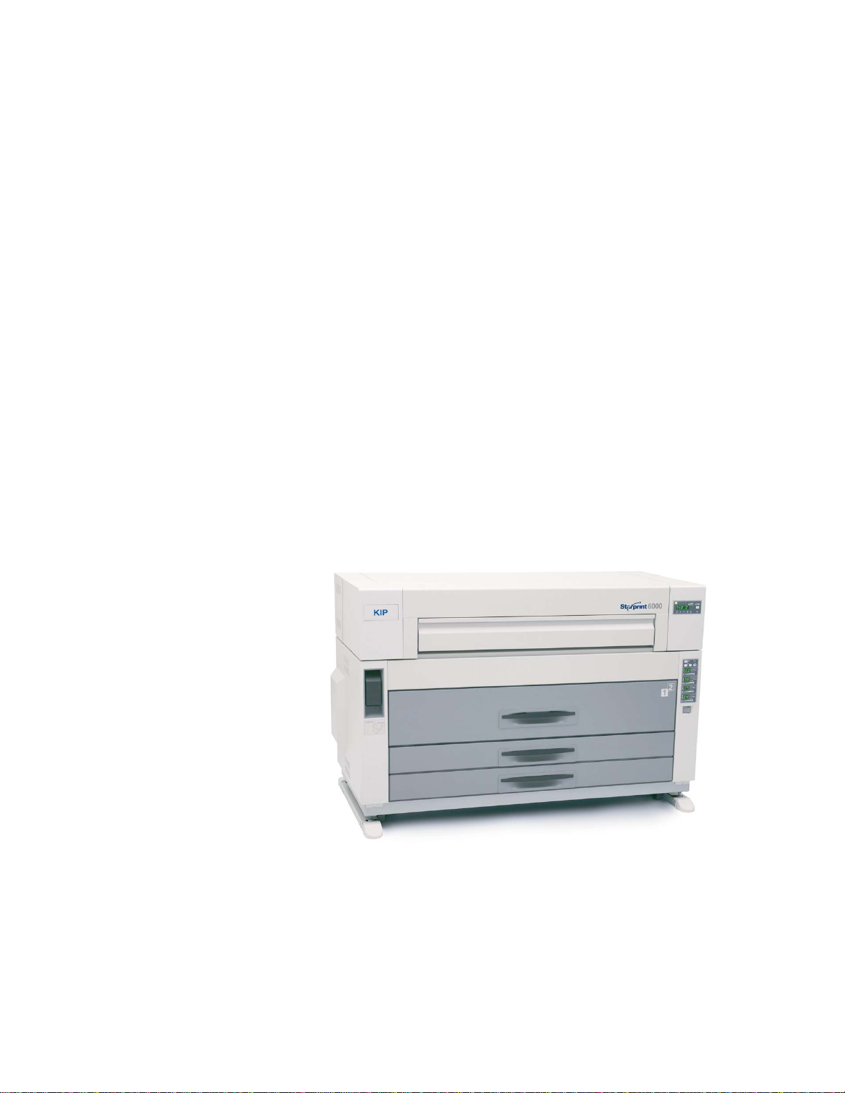
KIP Starprint 6000
User Guide
Version C.06
Page 2

Thank you for purchasing the Starprint 6000.
This USER'S MANUAL contains functional and operational explanations for the Starprint 6000.
Please read this USER'S MANUAL carefully before using the Printer.
Please keep this USER'S MANUAL for future reference.
This device complies with part 15 of the FCC Rules. Operation is subject to the following two
conditons.
(1) This device may not cause harmful interference
(2) This device must accept any interference received, including interference that may cause
undesired operation.
Do not install Machine around other electronic equipment or other precision instruments.
Other devices may be effected by electrical noise during operation.
If the Machine is installed near other electronic equipment, such as a TV or a radio,
interference to said equipment, such as noise or flickering, may occur.
Use a separate power line and install the PRINTER as far as possible from said equipment.
As an ENERGY STAR ® Partner, Katsuragawa Electric Co., Ltd. has
determined that this product meets the
energy efficiency.
The International
promotes energy saving through the penetration of energy efficient computers and other office
equipment. The program backs the development and dissemination of products with functions that
effectively reduce energy consumption. It is an open system in which business proprietors can
participate voluntarily. The targeted products are office equipment such as computers, monitors,
printers, facsimiles, copiers, scanners, and multifunction devices. Their standards and logos are
uniform among participating nations.
ENERGY STAR ® Office Equipment Program is an international program that
ENERGY STAR ® guidelines for
(1)
Page 3

Safety Warnings
The following warnings are very important in order to safely use this product.
These notes are important in preventing danger to the operator or operation of the printer.
The following symbols are found throughout the USERS Manual and have the following meaning:
WARNING
This WARNING mark means that there is a possibility of death or serious
injury if you ignore or do not follow the said instruction.
CAUTION
This CAUTION mark means that there is a possibility of injury or physical
damage if you ignore or do not follow the said instruction.
When marked with this symbol, “ DO NOT ATTEMPT”
When marked with this symbol, “pay close attention to”
(2)
Page 4
WARNING
Ground the product with a correct ground source or you may be electrically
shocked.
1. The Power source should be as follows:
2. Use a circuit with a dedicated breaker.
3. Install the product as close to the wall outlet as possible.
4. If you wish to move the printer, please contact your service personnel.
1. Do not remove the screw and do not open the cover if not instructed to
do so in this User’s Manual. If you ignore this warning, you may be burnt
or receive an electric shock due to a hot item or electrically charged part
inside of the printer.
2. Do not disassemble or tamper with the printer.
It may result in a fire or an electrical shock.
1. Do not plug in the printer into a multi-wire connector in which some other
equipment is plugged into.
It may cause a fire due to outlet overheating.
2. Do not damage the Power Cord by stepping on or placing heavy items
on it.
If the Power Cord is damaged, it may cause a fire or you may receive
an electric shock. REPLACE THE CORD IF DAMAGED!
1. Do not put a flower vase, a flowerpot or any water-filled item on the
product.
Spilt water could cause a fire or an electric shock.
2. If the product generates an abnormal smell or noise, turn it off and
unplug it from the wall electrical outlet immediately.
Do not throw the toner into a fire or other sources of heat, as it can
explode.
120V plus or minus 10%, 16A and 50/60Hz
(3)
Page 5
CAUTION
Do not install the printer in a humidified room or a dusty room.
Also, do not install the printer on an unstable floor as injuries may occur.
1. Unplug the printer before you move it.
The power cord may be damaged and it may result in a fire or electric
shock.
Do not pull the cord when you unplug the printer as you may damage the
Power Cord.
There are hot items inside of the printer.
Take great care not to touch these items when you remove mis-fed media.
Ventilate the room well if you print in a small area.
2. If you do not use the printer for a long duration (holidays, company
shutdown) turn off and unplug the printer from the outlet for safety.
(4)
Page 6

TABLE OF CONTENTS
Chapter 1 Before Printer Use
Page
1.1 Installation Requirements 1- 2
1.2 Originals Prohibited from Duplication 1- 3
1.3 Features 1- 4
1.4 Specifications 1- 5
1.5 Available Print Sizes 1- 7
1.5.1 Available widths 1- 7
1.5.2 Available lengths 1- 7
1.6 Appearance 1- 8
1.6.1 Front view 1- 8
1.6.2 Rear view 1- 9
1.6.3 Operation Panel 1-10
1.6.4 Media Indicator 1-12
1.6.5 Counter Indication Method 1-14
1.7 Indications during Normal Use 1-15
Chapter 2 Basic Operations
Page
2.1 Turning on the Printer 2- 2
2.2 Turning off the Printer 2- 4
2.3 Installing Roll Media into a Roll Deck 2- 5
2.4 Installing Toner 2-13
Chapter 3 Advanced Operations
3.1 Changing the Density Level 3- 2
3.2 Dehumidifying the Roll Media 3- 3
3.3 User Mode 3- 5
3.3. 1 User Mode 0 3- 6
3.3. 2 User Mode 1: Image Enhancement Setting Mode 3- 7
3.3. 3 User Mode 2: Auto Power Off Timer Setting Mode 3- 9
3.3. 4 User Mode 3: Auto Power Off Setting Mode 3-10
3.3. 5 User Mode 4: Cold Sleep Timer Setting Mode 3-11
3.3. 6 User Mode 5: Cold Sleep Setting Mode 3-13
3.3. 7 User Mode 6: Warm Sleep Timer Setting Mode 3-14
3.3. 8 User Mode 7: Warm Sleep Setting Mode 3-16
3.3. 9 User Mode 8 3-17
(5)
Page 7

Page
3.3.10 User Mode 9: Low Temperature Environment Setting Mode 3-18
3.3.11 User Mode A: H/H Environment Setting Mode 3-19
Chapter 4 Error Indications and Correction
Page
4.1 Paper Mis-feed Errors 4- 2
4.1.1 Paper mis-feed in Roll Deck Section (J-01, J-02, J-03 and J-04) 4- 3
4.1.2 Paper mis-feed in Manual Feeder Section (J-05) 4- 5
4.1.3 Paper mis-feed in Paper Feeder Section (J-10, J-11 and J-12) 4- 6
4.1.4 Paper mis-feed in Fuser Section (J-13 and J-14) 4- 8
4.2 Open Cover Errors 4-11
4.2.1 Roll Deck Open (U-01, U-02 and U-03) 4-11
4.2.2 Lever / Toner Cover Open (U-05) 4-12
4.2.3 Exit Cover Open (U-06) 4-13
4.3 Other Errors 4-14
4.3.1 Toner Low 4-14
4.3.2 Roll Empty 4-15
4.3.3 No Manual Paper 4-16
4.4 Call Service Errors 4-17
(6)
Page 8

Chapter 1
Before Printer Use
Page
1.1 Installation Requirements 1- 2
1.2 Originals Prohibited from Duplication 1- 3
1.3 Features 1- 4
1.4 Specifications 1- 5
1.5 Available Print Sizes 1- 7
1.5.1 Available widths 1- 7
1.5.2 Available lengths 1- 7
1.6 Appearance 1- 8
1.6.1 Front view 1- 8
1.6.2 Rear view 1- 9
1.6.3 Operation Panel 1-10
1.6.4 Media Indicator 1-12
1.6.5 Counter Indication Method 1-14
1.7 Indications during Normal Use 1-15
Chapter 1 Before Use 1-1
Page 9
1. 1 Installation Requirements
The following conditions are required for installation of the equipment.
1. Power source should be rated as follows.
120V plus or minus 10%, 16A and 50/60Hz
2. The equipment must be on an exclusive circuit.
3. The outlet must be near the equipment and easily accessible.
1. Make sure to connect this equipment to a grounded outlet.
2. For PLUGGABLE EQUIPMENT, the socket-outlet shall be installed near
the equipment and shall be easily accessible.
The site temperature range = 10 to 32 degrees centigrade, with the humidity between
15% to 85% RH. (NON CONDENSING)
Keep the printer away from water sources, boilers, humidifiers or refrigerators.
1. The installation site must not have open flames, dust or ammonia gases.
2. The equipment must not be exposed to the air vents from air conditioners.
It may affect the image quality.
3. The equipment should not be exposed to the direct sunlight.
Please draw curtains to block any sunlight.
When you open the Upper Unit to remove a mis-feed, do not expose the
Photoconductive Drum to strong (intense) light as this will damage the Drum.
Ozone will be generated while this equipment is use, although the quantity generated
is within safe levels. (see certifications)
Ventilate the room, if required.
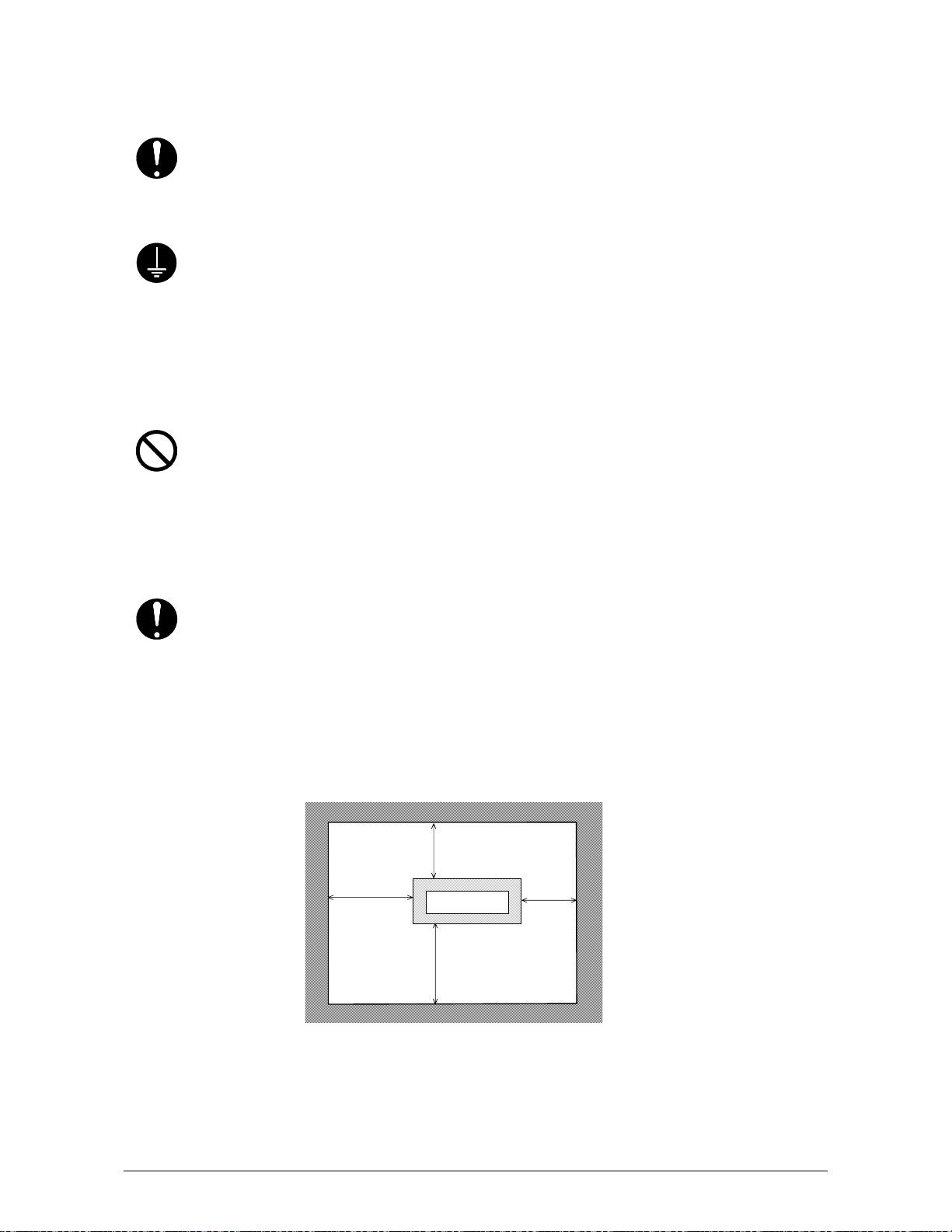
Keep ample room around the equipment to ensure comfortable operation.
(Refer to the following figure.)
The equipment must be levelled and the floor strength must be ample to sustain the
weight of the equipment.
100cm or
wider
60cm or wider
Rear side
Printer
Front side
100cm or wider
60cm or
wider
Chapter 1 Before Use 1-2
Page 10
1. 2 Originals Prohibited to Copy
It is not necessarily allowed to copy every kind of original.
You may be punished by the law if only you possess the copy of some kind of original.
We recommend you to consider enough before you copy such original.
[Originals prohibited from copying by the law]
1. It is not allowed to copy Currency (Bill, Money, Bank Note, etc.), Government issued
Negotiable Instruments (National Bonds, Security, Local Debt Bonds, etc.).
2. It is not allowed to copy Foreign Currency or Foreign Negotiable Instruments.
3. It is not allowed to copy unused postal stamps or government postcards without permission
to make replica from Government,
4. It is not allowed to copy Government issued revenue stamps, certificate stamps which are
prescribed by Liquor Tax Act or the Commodity Tax Act.
[Special items to be cared]
1. It is warned by the government to copy private issued securities (stock certificate, draft,
check, goods ticket, etc.), commutation ticket or book of tickets, excluding that some specific
company copies such originals as many as it requires for its own business.
2. We recommend you not to copy freely such originals as government issued passport, public
or private issued licenses, automobile inspection certification, Ids and tickets like pass or
meal.
Reference Law Prohibited items to copy
Regulations to control fake currency and
Bond.
Control Law against Forged & faked
Foreign Currency, Bill, Bank Note and Bond
Forged postal stamps control law Unused postal stamps or government postcards
Forged revenue stamps control law Government issued revenue stamps, and
Currency similarity securities Control Law Private issued securities (stock, draft, check,
[Originals protected by the copyright]
It is prohibited to copy such originals as book, music, paintings, printed copy, maps, drawings,
movie and pictures which are protected by the copyright, except for personnel or family use or
similar purpose.
Currency (Bill, Money, Bank Note, etc.),
Government issued Negotiable Instruments
(National Bonds, Security, Local Debt Bonds,
etc.)
Foreign Currency or Foreign Negotiable
Instruments
certificate stamps prescribed by Liquor Tax Act
or Commodity Tax Act
goods ticket, etc.), commutation or book tickets
Chapter 1 Before Use 1-3
Page 11

1. 3 Features
(1) Starprint 6000 Digital Printer can make a print in a speed of 100mm per second.
The maximum print width is 36 inches, and the minimum is 8.5 inches.
(2) The print image is more stabilized than before since we adopt a minute toner with a
mono-component non magnetic development system.
(3) High quality print image is achieved using the HDP Process.
(4) No Waste Toner
Chapter 1 Before Use 1-4
Page 12
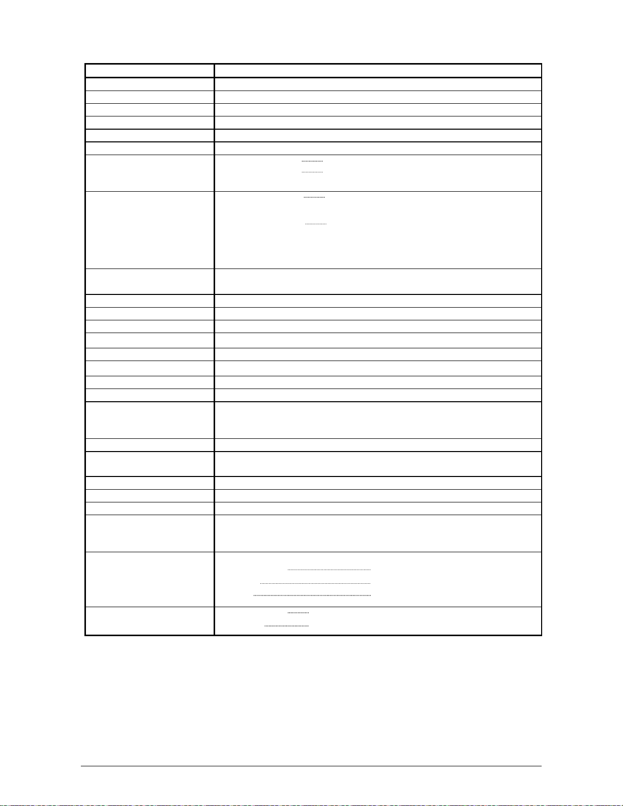
1. 4 Specifications
Item Specification
Model Starprint 6000
Configuration Console
Printing method LED Array Electro Photography
Photoconductor Organic Photoconductive Drum
Print speed 100mm per second (4 E per minute)
Resolution 600dpi
Print width Maximum width 36 inches
Minimum width 11 inches (Roll Media)
8.5 inches (Cut Sheet )
Print length Maximum length 19.2 ft ( 6m ) (Standard)
24m or unlimited (Optional)
Minimum length 8.5 inches
NOTE : If the print is longer than 6m, we do not guarantee image
quality or the reliability of media feeding systems.
Cassette(Option) 8.5” x 11”, 11” x 8.5”, 11” x 17”, 17” x 11”, 22” x 17”, 24” x 18”
200 sheets / Cassette (Plain Paper)
Warm up time 120V = less than 8 minutes
First print time 24 seconds (E print from 1st Roll Deck)
Fusing method Roll Fuser
Development method Dry type with non-magnetic mono-component toner
Exposure method LED
Charging method Corona
Transfer method Corona
Separation method Corona
Media feeding method 1. Automatic (2 Roll Decks) + Manual
2. Automatic (4 Roll Decks) + Manual
3. Automatic (2 Roll Decks) + Manual + Cassette (Option)
Input power 120V plus or minus 10%, 16A and 50/60Hz
Maximum power
consumption
Acoustic noise Less than 55db (Stand by) / Less than 60db (Printing)
Ozone Smaller than 0.1ppm (Average)
Dimensions 1420mm (Width) x 625mm (Depth) x 900mm (Height)
Weight 230kg (In case of 2 Roll Decks Model)
Media (Recommended Media)
Dehumidify Heater is ON
0.45kwh (Stand by) / 1.54kwh (Printing)
270kg (In case of 4 Roll Decks Model)
280kg (In case of 2 Roll Decks + 2 Cassettes Model)
Plain Paper US Bond (PB-20)
Vellum US Vellum (XV-20)
Film 4MIL (XPD-4X)
Environmental condition
for usage
NOTE :
1. The above specifications may change without notice.
2. Due to the characteristics of Vellum, it is easy to be affected to the temperature or
humidity.
Under the extreme environment, such as high temperature / high humidity or low
temperature / low humidity, it may have a case of wrinkling problem if you use the
loaded Vellum Roll.
In case of this, adjust the room environment to the normal condition.
Temperature 10 to 32 degrees centigrade
Humidity 15 to 85% RH
Chapter 1 Before Use 1-5
Page 13

3. [Storage of Consumables]
Media Wrap the media surely to shut out the humidity.
Toner Toner cartridge Store the cartridge within the temperature range from
0 to 35 degrees centigrade and within the humidity range from 10 to
85% RH.
Chapter 1 Before Use 1-6
Page 14
1. 5 Available Print Sizes
1. 5. 1 Available widths
Available widths are from 8.5 inches to 36 inches.
It is possible to use the any of the following widths of media.
36, 34, 30, 24, 22, 18, 17, 12, 11, 9 and 8.5 inches
1. 5. 2 Available lengths
Available lengths are from 8.5 inches to 6 meters.
NOTE
It is possible to print longer than 6 meters as an option.
You can choose either “24m” or “unlimited” as a maximum print length.
Call your service personnel if you would like to print over 6m as the user can not
change this setting in the printer.
Important !
If you print longer than 6 meters, we are unable to guarantee image quality or the
reliability of media feeding system.
Chapter 1 Before Use 1-7
Page 15
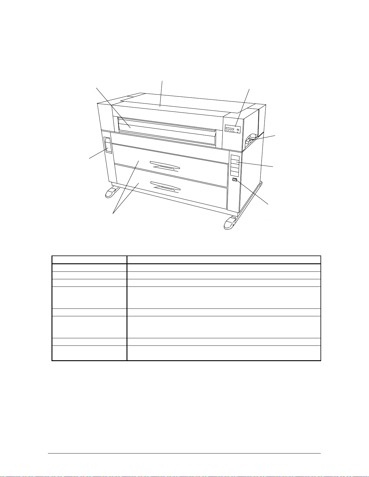
1. 6 Appearance
1. 6. 1 Front view
Toner Cover
Manual Table
Lever
Operation Panel
Dehumidify
Heater Switch
Media Indicator
Power Switch
Roll Decks
Name of part Function
Manual Table Open to insert a sheet of paper, or to pull the Upper Frame Unit.
Toner Cover Open the Toner Cover when you replace the Toner Cartridge.
Lever Pull the Lever forward to release the Internal Paper Feeder.
Roll Decks Each Roll Deck holds 2 rolls of print media, and the bottom Deck
is possible to replace to Cassette.
(Cassette Deck is the option.)
Operation Panel Printer information and error codes are indicated on this panel.
Media Indicator Change the indication of paper size and the kind of Media.
And such information and the remaining volume of individual deck
is indicated here.
Power Switch Press “ON” to turn on the printer, and press “OFF” to turn it off.
Dehumidify Heater
Switch
Press “H” to turn on the Dehumidify Heater, and press “L” to turn it
off.
Chapter 1 Before Use 1-8
Page 16
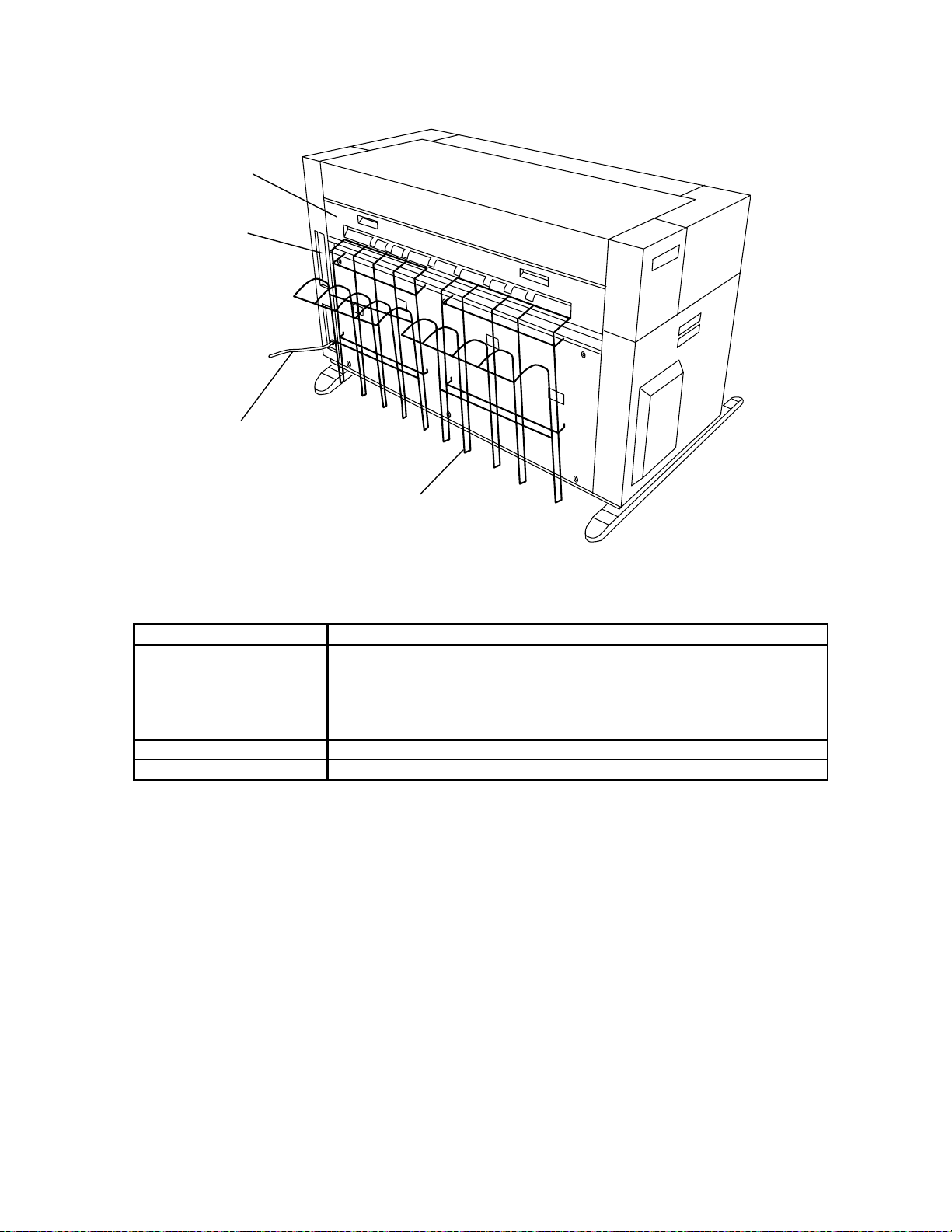
1. 6. 2 Rear view
Exit Cover
Interface
Terminal
Power Cable
Tray
Name of part Function
Exit Cover Open the Exit Cover when you remove jammed media.
Interface Terminal Connect the COPY cable to this terminal, which is included with the
KIP 2000 Series Scanners
D-Sub Connector, 37pin: max.5Vdc(large)
(D-Sub Connector, 9pin: max.12Vdc(small))
Tray Prints which exit from the Printer are stacked by the standard Tray.
Power Cable Connect to the outlet.
Chapter 1 Before Use 1-9
Page 17
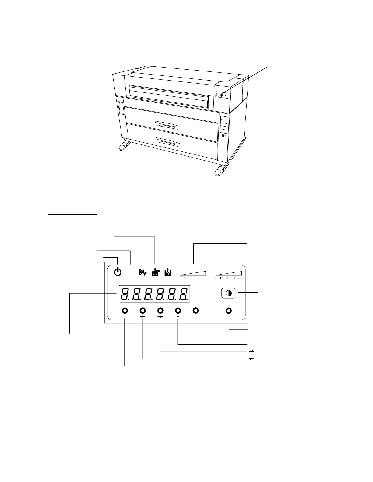
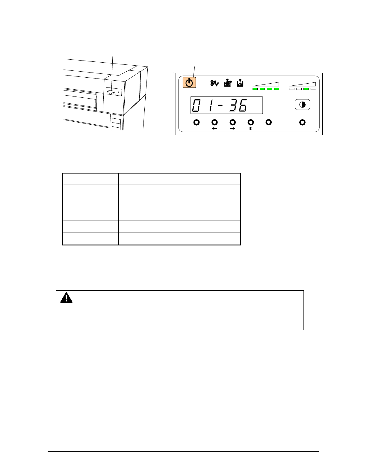
1. 6. 3 Operation Panel
There is an Operation Panel on the top of the printer.
Refer to the following page for indicators and key functions.
Operation Panel
Operation Panel
Toner Low Indicator
Roll Empty Indicator
Paper Mis-feed Indicator
Job Indicator
Ready Indicator
Displ ay
Toner Remaining Indicator
Image Density Indicator
Density Selection Key
job
TONER REMAI N IMAGE DENSI TY
MENU ENTER TEST
Test Print Switch
Enter Key
*(Asterisk) Key
(Arrow) Key
(Arrow) Key
Menu K ey
Chapter 1 Before Use 1-10
Page 18
Name of part Function
Toner Low Indicator Toner Low Indicator lights red when there is not enough toner in the
Developer Unit.
In case dark image is continuously printed, printing may be held
temporarily and this indicator flashes red.
Roll Empty Indicator Roll Empty Indicator lights red when the roll media in the selected
Roll Deck is empty.
It may also light when the roll media is not correctly installed.
Paper Mis-feed Indicator Paper Mis-feed Indicator lights red when the printer or accessory
fails to feed the media.
A mis-feed code is indicated on the Display if this occurs.
Job Indicator Job Indicator lights green when the printer receives a print job from
the scanner or controller.
Ready Indicator Ready Indicator lights orange when the printer is warming up or
printing is prohibited.
It lights green when the printer is standby or during printing.
In case printing is continuously taken, and the temperature of the
fuser goes down to a certain level, printing may be held temporarily
and this indicator flashes green.
Display The Display normally shows green which Roll Deck is selected and
the width of the roll media in said Roll Deck.
It also indicates an error code if the printer has an error such as
“paper mis-feed” or “door open”.
Toner Remaining
Indicator
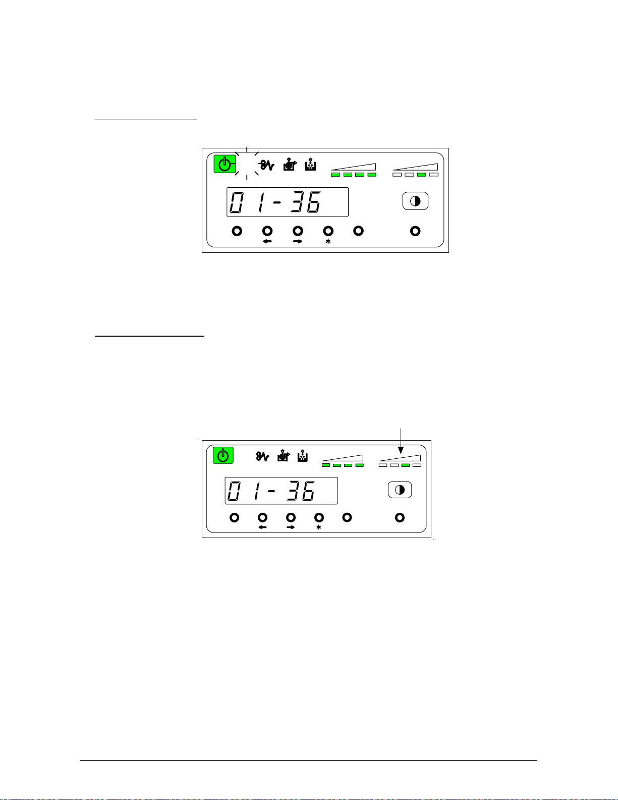
Image Density Indicator Image Density is indicated green with every 1/4 step.
Density Selection Key You may change the density level by pressing the Density Selection
Test Print Switch A test pattern will be printed out if you press the Test Print Switch.
Enter Key Selected job is defined. (User Mode)
* (Asterisk) Key Function selection ( User Mode )
(Right Arrow) Key Mode selection (Increment) ( User Mode )
(Left Arrow) Key Mode selection (Decrement) ( User Mode )
Menu Key Menu selection ( User Mode )
Note: In case a Cut Sheet Paper is inserted manually, size and media are not indicated on this
Operation Panel.
Toner Remaining Volume is indicated green with every 1/4 step.
: Toner remains more than 3/4.
: Toner remains more than 2/4.
: Toner remains more than 1/4.
: Toner remains less than 1/4.
(Strobe time is adjusted.)
: Darker
: Normal
: Lighter
: Lightest
Key.
(Service purpose only.)
Chapter 1 Before Use 1-11
Page 19
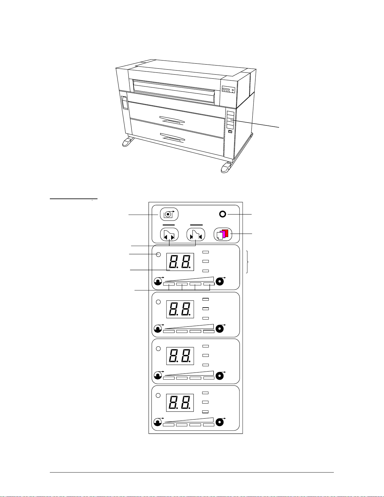
1. 6. 4 Media Indicator
There is a Media Indicator on the right side of the front of the printer.
Refer to the following page for indicators and key functions.
Media Indicator
Media Indicator
Roll Selector
Paper Width Sel ector
Roll Indicator
Size Indicator
Roll Remaining
Volume Indicator
1
2
3
4
PAPER TRIM
DECK
WIDT H MEDI A
PLAIN PAPAR
VELLUM /
TRACING
FILM
PLAIN PAPAR
VELLUM /
TRACING
FILM
PLAIN PAPAR
VELLUM /
TRACING
FILM
PLAIN PAPAR
VELLUM /
TRACING
FILM
Cut Key
Media Selector
Media Indicator
Chapter 1 Before Use 1-12
Page 20
Name of part Function
Roll Selector Press this Key when paper width or Media is changed.
Roll Indicator lights orange.
Paper Width Selectors Press and select the desired Paper Width.
Indication is changed as follows.
36 34 30 24 22 18 17 12 11
Roll Indicator Selected Roll lights orange.
In case of the Manual Paper is selected, no Roll Indicator is lit.
Size Indicator Selected paper width is indicated here.
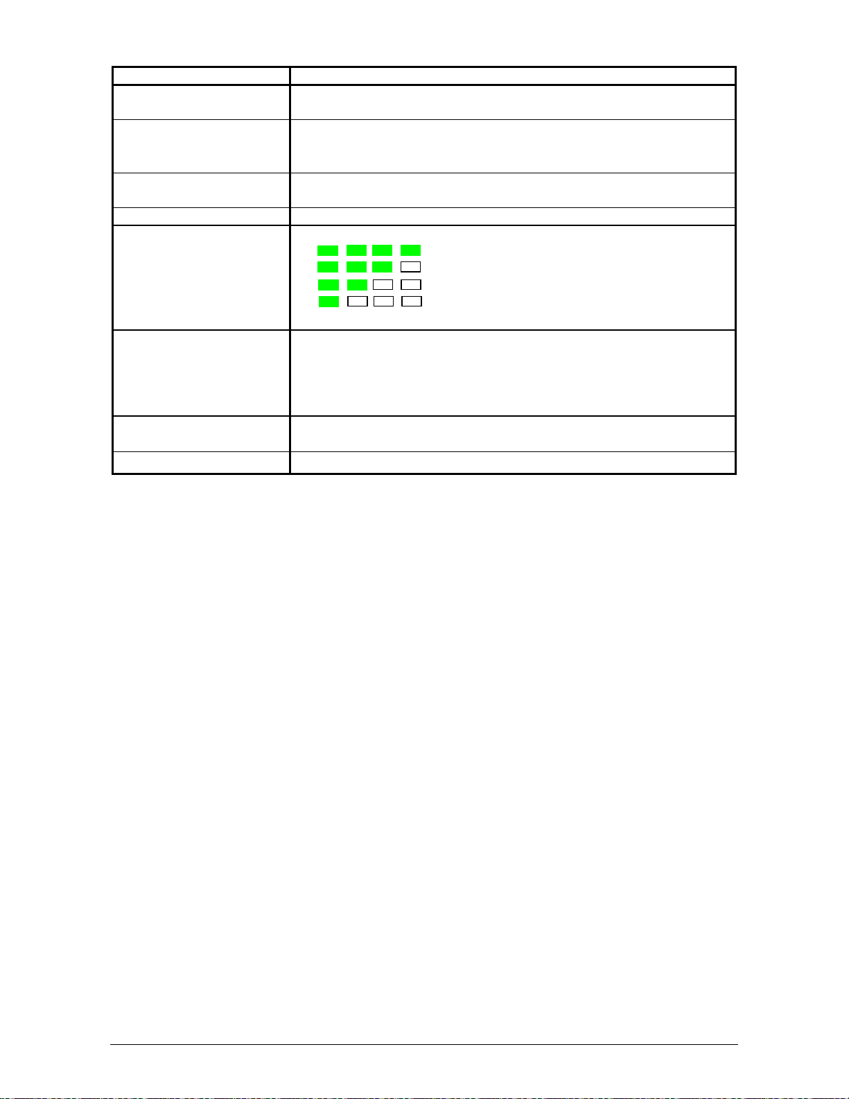
Roll Remaining Volume
Indicator
Cut Key (Trim) When JAM has occurred, and if the Roll is not cut yet at that
Media Selector Press and select the proper media, such as Plain Paper, Vellum
Media Indicator Selected Media lights.
Roll Remaining Volume lights green with every 1/4 step.
: Paper remains more than 3/4.
: Paper remains more than 2/4.
: Paper remains more than 1/4.
: Paper remains less than 1/4.
In case of “No Paper”, far left indicator turns on red.
moment, press this key to cut the Roll.
Cutter will work just once.
If the Cutter works once, it does not work any more even if this key
is pressed repeatedly.
or Film.
Chapter 1 Before Use 1-13
Page 21
1. 6. 5 Counter Indication Method
Hard Counter
1
2
3
4
PAPER TRIM
DECK
WIDT H MEDI A
PLAIN PAPAR
VELLUM /
TRACING
FILM
PLAIN PAPAR
VELLUM /
TRACING
FILM
PLAIN PAPAR
VELLUM /
TRACING
FILM
PLAIN PAPAR
VELLUM /
TRACING
FILM
The value of the Counter is displayed
during pressing the [TRIM] key,
under any deck is not selected,
(Example)
Counter = 0123456
NOTE
If [TRIM] key is pressed while [Roll
Indicator] lights orange (A certain deck
is selected.), the initial cut is performed
as usual.
Chapter 1 Before Use 1-14
Page 22
1. 7 Indications during Normal Use
The Operation Panel indicates the following information during normal use.
(1) Processing a print
The Job Indicator lights green when the printer receives a job.
(2) Image Density level
Any of the 4 LEDs of the Image Density Indicator will light according to the density level you
selected.
Image density becomes darker when you select LEDs further right.
Refer to [3.1 Changing the Density Level] on the page 3-2 as for the way to change
the Image Density Level.
job
TONER REMAIN IMAGE DENSI TY
MENU ENTER TEST
Image Density Indicator
job
TONER REMAIN IMAGE DENSITY
MENU ENTER TEST
Chapter 1 Before Use 1-15
Page 23
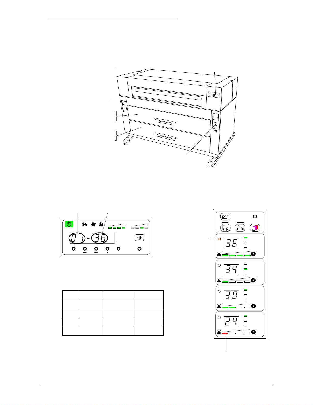
(3) Roll Deck, roll width and roll material currently used
Before printing, you can select on the controller or on the scanner which roll media is used
for printing.
The Display of the Operation Panel indicates the selected Roll Deck Number and the
media width.
The Media Indicator indicates the media width, the material of the roll (Plain paper,
Vellum or Film) and the remaining volume of individual deck.
Operation Panel
Roll 1 (Front Side)
Roll 2 (Rear Side)
Roll 3 (Front Side)
Roll 4 (Rear Side)
Media Indicator
Example : Roll media in the Roll 1 is selected.
Roll Deck No. Paper Wi dth
job
TONER REMAIN IMAGE DENSITY
MENU ENTER TEST
It li ghts
orange.
WIDTH MEDI A
1
2
PAPER TRIM
DECK
PLAIN PAPAR
VELLUM /
TRACING
FILM
PLAIN PAPAR
VELLUM /
TRACING
FILM
Other information:
PLAIN PAPAR
VELLUM /
TRACING
FILM
PLAIN PAPAR
VELLUM /
TRACING
FILM
Deck Width Material Remaining
1 36 Plain Full
2 34 Vellum 1/4
3 30 Plain 2/4
4 24 Plain Empty
3
4
Note: In case Roll of the deck is empty, far left
turns red while other 3 LEDs turn off.
In case of "No Paper",
this LED lights red.
Chapter 1 Before Use 1-16
Page 24

Chapter 2
Basic Operations
Page
2.1 Turning on the Printer 2- 1
2.2 Turning off the Printer 2- 4
2.3 Installing Roll Media into a Roll Deck 2- 5
2.4 Installing Toner 2-13
Chapter 2 Basic Operations 2-1
Page 25

2. 1 Turning on the Printer
1) Plug the printer into an exclusive wall outlet.
WARNING
(1) Do not handle the Power Plug with wet hands, or you may receive an electrical shock.
(2) Ground the printer for safety.
(3) Do not plug the printer into a multi-wiring connector in which other devices are
plugged into. It may overheat the outlet and may result in a fire.
(4) The outlet must satisfy the following rated power condition.
120V plus or minus 10%, 16A and 50/60Hz
2) There is a Power Switch (A) on the right-front of the printer.
Press “ON” to turn on the printer.
A
A
ON OFF
Chapter 2 Basic Operations 2-2
Page 26
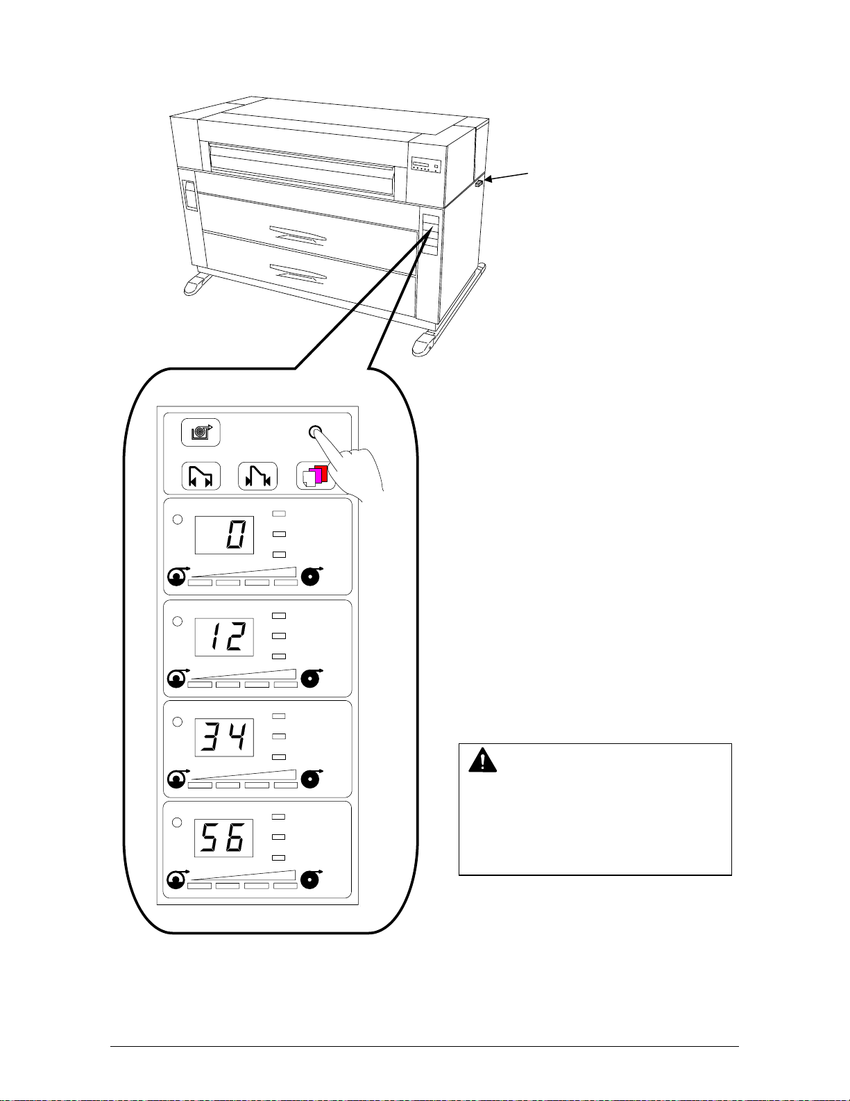
3) There is an Operation Panel (B) on the right-front of the printer.
The Ready Indicator (C) on the Operation Panel lights orange showing that the printer is now
warming up.
B
C
job
TONER R EMAIN I MAGE DENSIT Y
MENU ENTER TEST
Meaning of Ready Indicator (C)
Status Meaning
OFF Power is turned off
Orange lighting During warming up
Orange flashing This machine is in the sleep mode.
Green lighting Ready / Printing
Green flashing Down sequence mode caused by fuser.
4) When the printer has reached a certain temperature, the Ready Indicator will light green.
This may take up to 8 minutes from room temperature.
NOTE
It is impossible to make any prints when the Ready Indicator is orange.
Please wait until the light becomes green before prints will or can be produced.
5) Print from your computer or copy from the scanner.
Chapter 2 Basic Operations 2-3
Page 27
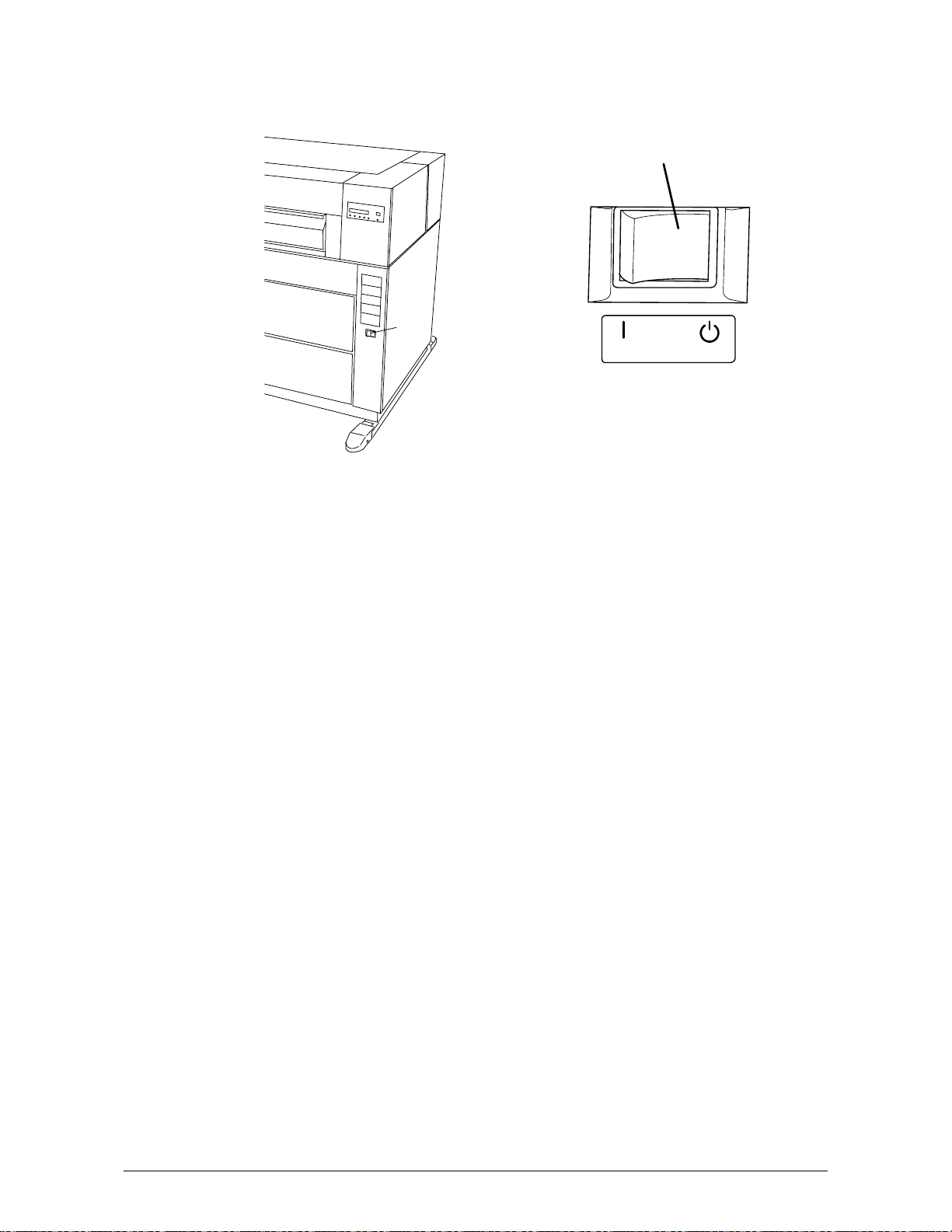
2. 2 Turning off the Printer
1) Press “OFF” on the Power Switch (A) to turn off the printer.
A
A
ON OFF
Chapter 2 Basic Operations 2-4
Page 28

2. 3 Installing Roll Media into a Roll Deck
NOTE
The printer indicates a “Roll Empty Error” by lighting up the Roll Empty Indicator on the
Operation Panel if the roll media currently used is consumed during printing.
Install a new roll media using the following directions:
Roll Empty Indicator
1) When the Roll Empty Indicator lights, check the Roll Deck Number on the Seven Segments
Indicator to see which Roll Deck is empty.
Example : Roll Deck Number is “01”.
This means the media in the Roll 1 is empty.
2) Open the Roll Deck (A).
Rewind the remaining paper around its core
as shown arrow.
job
TONER REMAIN IMAGE DENSITY
MENU ENTER TEST
Roll Deck Number
job
TONER REMAIN IMAGE DENSI TY
MENU ENTER TEST
A
Chapter 2 Basic Operations 2-5
Page 29
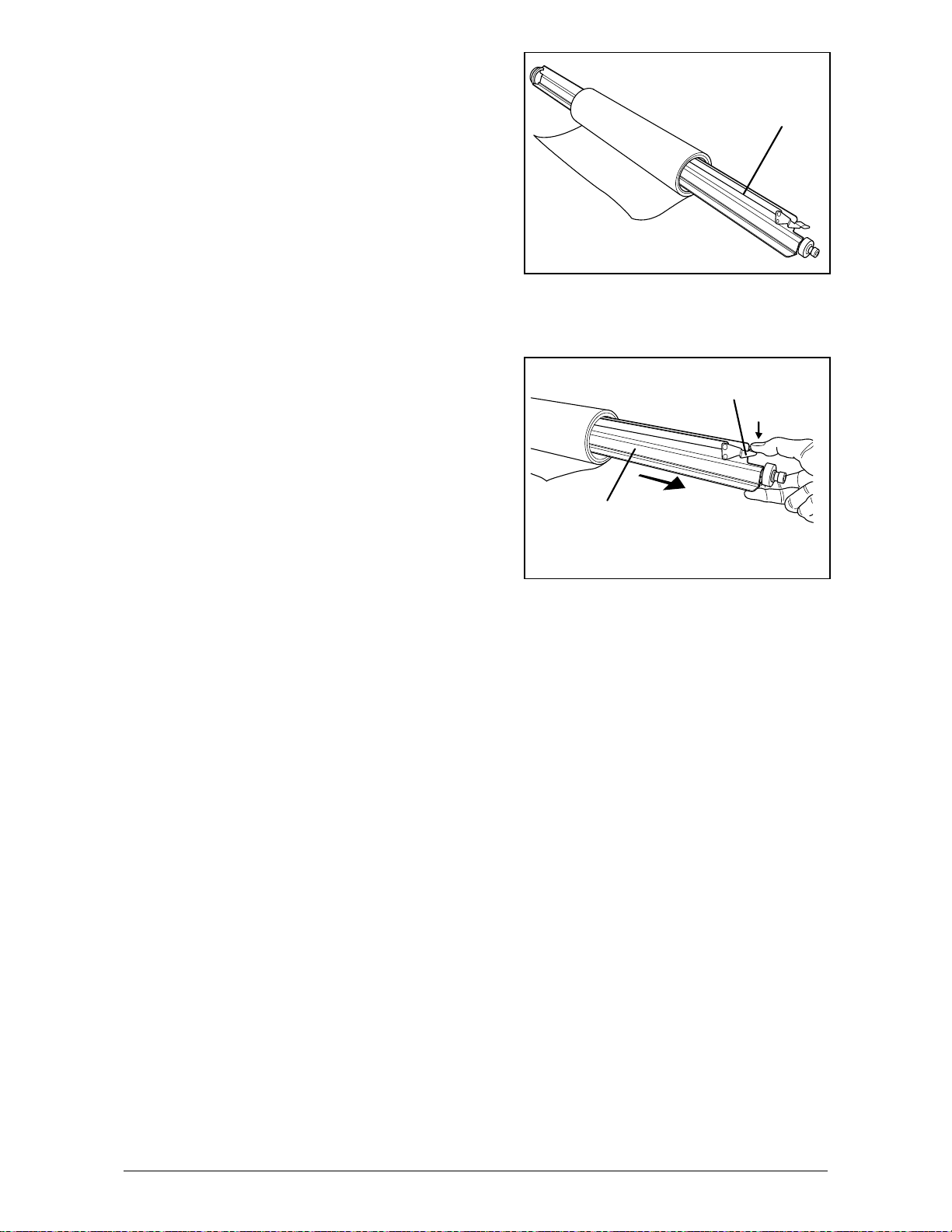
3) Remove the Roll Spool (B) from the Roll Deck.
4) Pressing down Lever (C), pull out the Roll Spool (B)
from the core of the roll.
B
C
B
Chapter 2 Basic Operations 2-6
Page 30

5) Loosen the Thumb Screw (D), and slide the Stopper (E) according to the width of the new roll
of media.
Tighten the Thumb Screw to fix the Stopper at the corresponding size mark.
E
D
NOTE
Align the top of triangle (F) of stopper and
the size mark (G).
G
F
A
0
Chapter 2 Basic Operations 2-7
Page 31
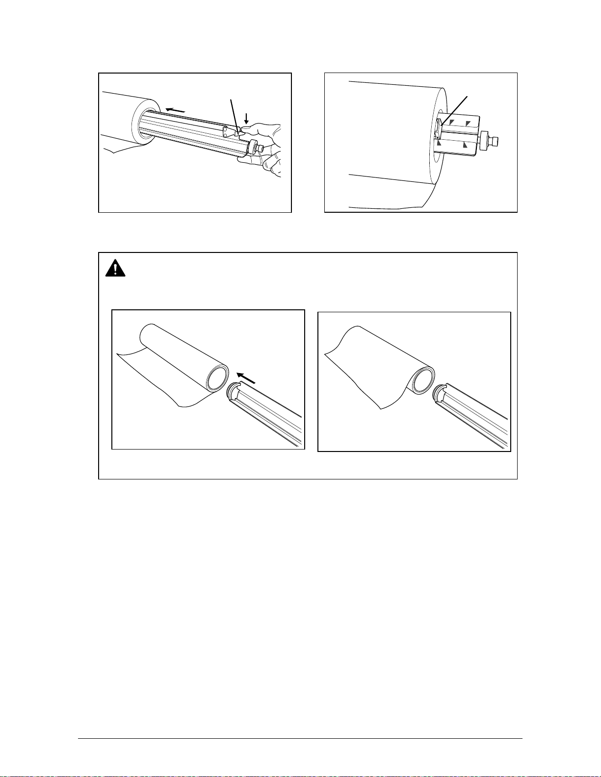
6) Pressing down the Lever (C), insert the Roll Spool fully into the core until the Stopper (E)
touches the roll media.
Then, release the Lever (C) to “catch” the roll media with the Roll Spool.
C
E
3
4
"
3
6
"
A
0
3
6
"
NOTE
Be careful of the winding direction of roll media.
Good
No good
Chapter 2 Basic Operations 2-8
Page 32

7) In case you load Roll 1 or Roll 3;
7-1) Put the Roll Spool into the Roll Deck.
(Gear side is on the left and Lever side
is on the right.)
Gear side
7-2) Rotate the green knob as shown arrow and feed
the leading edge of the media between Feeding
Rollers
Knob
Roll 1 Roll 2
Roll 3 Roll 4
Knob
Roll 1 Roll 2
Roll 3 Roll 4
Chapter 2 Basic Operations 2-9
Page 33

8) In case you load Roll 2 or Roll 4;
8-1) Put the Roll Spool onto the Operator aid Arm.
(Gear side is on the left and Lever side
is on the right.)
96um-78
8-2) Slide your right hand to deeper position, and
slide your left hand to deeper position,
not at the same time.
And then shift it to the far left.
NOTE “Operator aid Arm” was prepared to help the operator when you load
the roll paper on the deeper Deck.
Follow the above procedure for your safe.
8-3) Rotate the green knob as shown arrow and feed
the leading edge of the media between Feeding
Rollers
Knob
NOTE When you load the media, rotate the Paper Feeding Roller Knob.
the slit.
position.
Do not advance the media to the point where the leading edge is seen in
The media will fold, if you close the Roll Deck with the media in this
2
Knob
Roll 1 Roll 2
Roll 3 Roll 4
Arm
3
1
Chapter 2 Basic Operations 2-10
Page 34

9) Close the Deck and select the changed Roll Deck pressing [Roll Selector] on Media Indicator.
Set both the Media Width and the Media according to the width and the type of material.
Example : New Roll of 36 inches width plain paper is loaded in the Roll 1.
Roll Selector
PAPER TRIM
DECK
WID TH MEDI A
Media Selector
Paper Width Selector
1
PLAIN PAPAR
VELLUM /
TRACING
FILM
2
PLAIN PAPAR
VELLUM /
TRACING
FILM
3
PLAIN PAPAR
VELLUM /
TRACING
FILM
4
PLAIN PAPAR
VELLUM /
TRACING
FILM
Note: [Roll Selector] changes the Roll Deck.
1 Æ 2 Æ 3 Æ 4 Æ Manual (no LEDs turn on).
[Paper Width Selector] changes the paper width wider or narrower.
36 Æ 34 Æ 30 Æ 24 Æ 22 Æ 18 Æ 17 Æ 12 Æ 11
[Paper Width Selector] in case the Optional Cassette is selected.
8.5 Æ 9 Æ 11. Æ 11 Æ 12 Æ 17. Æ 18. Æ 22. Æ 24.
(If dot is appeared on the last digit, it means “landscape”.)
[Media Selector] changes the type of media.
PLAIN PAPER Æ VELLUM/TRACING Æ FILM
Chapter 2 Basic Operations 2-11
Page 35

NOTE
(1) Image may be removed from the sides of the print if you select a narrower size on the
Paper Width Selector than the actual roll media width.
If you select a narrower size than the installed width, the interior of the printer will
become dirty with toner.
And if you select a wider size than the installed width, the margin on both sides will
become wider.
Please set this correctly when installing a new roll of media.
(2) Each material type has the best temperature for fusing to fix the toner.
The printer controls the temperature based on the setting on the Media Selector.
The toner may easily removed from the media if you make a wrong media
selection and incorrect media information is sent to the scanner and controller.
Please set media information correctly when you install a new roll.
Printout with a proper setting
Wrong setting (Narrow)
Wrong setting (Wide)
Chapter 2 Basic Operations 2-12
Page 36

2. 4 Installing Toner
NOTE
The printer will indicate a “Toner Low Error” by lighting the Toner Low Indicator on the
Operation Panel.
Replace the Toner Cartridge with the new cartridge using the following procedure:
(Please use our regular consumable.)
Stay ON: Toner Low
Flashing: Down Sequence caused
by toner consumption.
job
MENU ENTER TEST
1) Open the Manual Table, and then open the Toner Cover.
Manual
Table
Toner
Cover
2) Push the Joint to rightward to make the Toner Cartridge free until the Joint is latched.
Joint
Toner Low Indicator
TONER REMAIN IMAGE DENSITY
Chapter 2 Basic Operations 2-13
Page 37

3) Press the Lever to left, and then rotate the Toner Cartridge (not the Cap of Cartridge) to the
arrow diretion to close the opening.
Approximately two rotations make the opening close, but turn the Toner Cartridge until it stops.
1
2
4) Keep pressing the Lever to left, and lift up the Toner Cartridge.
2
1
5) Shake a new Toner Cartridge several times left and right to make the toner smooth.
Chapter 2 Basic Operations 2-14
Page 38

6) Press the Lever to left, and put the new Toner Cartridge facing the opening downward. Insert
the far left Collar of the Toner Cartridge into the slot firmly.
2
3
1
7) Pull the Toner Cartridge to rightward a little, and insert the swelling in the slot.
1
8) Rotate the Toner Cartridge to backward at least 90 degrees.
(The new Toner Cartridge is closed firmly for the transportation)
NOTE
Even if the Joint is not fit to the Toner
Cartridge, when you turn on the power,
it is automatically fit properly.
9) Close the Toner Cover, and then close the Manual Table.
2
Chapter 2 Basic Operations 2-15
Page 39

Chapter 3
Advanced Operations
Page
3.1 Changing the Density Level 3- 2
3.2 Dehumidifying the Roll Media 3- 3
3.3 User Mode 3- 5
3.3. 1 User Mode 0: Image Area Expanded Mode 3- 6
3.3. 2 User Mode 1: Image Enhancement Setting Mode 3- 7
3.3. 3 User Mode 2: Auto Power Off Timer Setting Mode 3- 9
3.3. 4 User Mode 3: Auto Power Off Setting Mode 3-10
3.3. 5 User Mode 4: Cold Sleep Timer Setting Mode 3-11
3.3. 6 User Mode 5: Cold Sleep Setting Mode 3-13
3.3. 7 User Mode 6: Warm Sleep Timer Setting Mode 3-14
3.3. 8 User Mode 7: Warm Sleep Setting Mode 3-16
3.3. 9 User Mode 8: Short Interval Setting Mode 3-17
3.3.10 User Mode 9: Low Temperature Environment Setting Mode 3-18
3.3.11 User Mode A: H/H Environment Setting Mode 3-19
Chapter 3 Advanced Operations 3-1
Page 40

3. 1 Changing the Density Level
If you would like to make the image darker or lighter, you will change the density level on the
scanner or controller.
After specifying the density level on the scanner or controller, it is also possible to compensate the
image density on the printer, if needed.
job
MENU ENTER TEST
When density level 3 is selected (3rd from left lights), the density level specified on the scanner
or controller is used without any compensation.
To make the image darker, select the density level 4.
To make it lighter, select the level 2.
To make it much lighter, select the level 1.
(Press the Density Selection Key to change the density level.)
NOTE
If you change the density level on the scanner or controller, you can make the image darker
or lighter without any compensation on the printer.
We strongly recommend you to adjust the density level on the scanner or controller rather
than on the printer.
Image Density Indicator
TONER REMAIN IMAGE DENSITY
Image Density Indicator
Level 1 Level 4
IMAGE DENSI TY
Density Select ion Key
Chapter 3 Advanced Operations 3-2
Page 41

3. 2 Dehumidifying the Roll Media
If the roll media has too much moisture, the toner may not be fixed correctly to the media.
It may be easily removed from the media.
If the room is much humidified, turn on the Dehumidify Heater to dehumidify the interior of the
printer.
There is a Dehumidify Heater Switch (A) inside of the machine.
Press “H” to turn on the Dehumidify Heater.
1) Lift up the Lever of the Internal Transportation Unit.
2) Open the Manual Table.
3) Pull out the Upper Frame Unit to your side.
(A) Dehumidify Heater Switch
Chapter 3 Advanced Operations 3-3
Page 42

NOTE
(1) There are several dehumidifying settings which can be set by the service personnel.
When these setting determine, the dehumidifier functions.
With any setting, the printer must be plugged in and the switch noted above must be
in the “ON” position.
Call your service personnel if you would like to change the switch setting.
Note that the user can not change the setting.
(2) To achieve the best image quality, we recommend that you use media that is unpacked
from the manufacture right before installing it into the printer.
If media is unpacked long before installation, poor image quality may occur.
(3) Re-appearance of image (solid black image especially) may occur if you print with a
humidified film.
When film is installed and the humidity is high (higher than 60%RH), we recommend
that you turn on the Dehumidify Heater.
Normal print Abnormal print
Re-appeared image
Chapter 3 Advanced Operations 3-4
Page 43
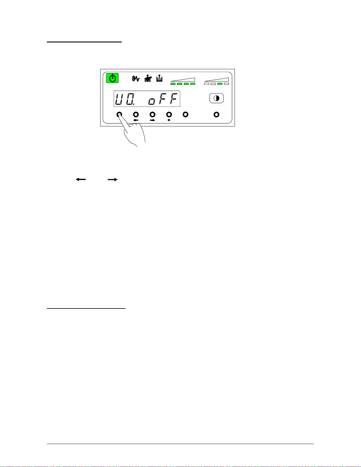
3. 3 User Mode
To enter in the User Mode
Press [Menu] key more than 3 seconds.
Then User Mode Number and its contents are displayed on the Display.
Pressing [ ] or [ ] key, you can change the User Mode.
U0. Image Area Expanded Mode p.3- 6
U1. Image Enhancement Setting Mode p.3- 7
U2. Auto Power Off Timer Setting Mode p.3- 9
U3. Auto Power Off Setting Mode p.3-10
U4. Cold Sleep Timer Setting Mode p.3-11
U5. Cold Sleep Setting Mode p.3-13
U6. Warm Sleep Timer Setting Mode p.3-14
U7. Warm Sleep Setting Mode p.3-16
U8. Short Interval Setting Mode p.3-17
U9. L/L Environment Setting Mode p.3-18
UA. H/H Environment Setting Mode p.3-19
To exit from the User Mode
Press [Menu] key again.
job
TONER REMAIN IMAGE DENSI TY
MENU ENTE R TEST
Chapter 3 Advanced Operations 3-5
Page 44

3. 3. 1 User Mode 0: Image Area Expanded Mode
Keep this mode always “oFF”. (Do not change this setting.)
In case this function is effective, Image Area may expand to right, left and trailing edge side.
However, this function does not guarantee about the image of trailing side.
In addition print ratio is reduced compare with the normal operation.
In order to select this function, press [Enter] key, then the selection is fixed.
U 0. o n : Image area is expanded.
U 0. o F F : Image area is not expanded.
Reference
In case you exit from this User Mode after you set this “Image Area Expanded Mode” ON,
a dot is displayed after hypen.
Dot after hypen
job
TONER REMAI N I MAGE DENSI TY
MENU ENTER TEST
job
TONER REMAI N IMAGE DENSITY
MENU ENTER TEST
Chapter 3 Advanced Operations 3-6
Page 45

3. 3. 2 User Mode 1: Image Enhancement Setting Mode
This mode allows you to select Image Enhancement function.
An isolated dot is enhanced and becomes visible much easier.
You can select the Image Enhancement Level for a scanner (A channel) and a controller
(B channel).
Also, it is possible to select whether the Smoothing Function is effective or not.
When the Smoothing Function is effetive, the image becomes much smoother and much clearer.
1) Select User Mode 1 “U1”, pressing [ ] or [ ] key.
Setting Value Contents
0 Dot Enhancement Level 0 : Not Enhanced
1 Dot Enhancement Level 1 : Isolated dot image is
enhanced.
2 Dot Enhancement Level 2 : Isolated dot image is
more enhanced.
3 Dot Enhancement Level 3 : Isolated dot image is
most enhanced.
4 Dot Enhancement Level 0 : Not Enhanced
5 Dot Enhancement Level 1 : Isolated dot image is
enhanced.
6 Dot Enhancement Level 2 : Isolated dot image is
more enhanced.
7 Dot Enhancement Level 3 : Isolated dot image is
most enhanced.
job
TONER REMAI N IMAGE DENSITY
MENU ENTER TEST
With
the Smoothing Function
Without
the Smoothing Function
Chapter 3 Advanced Operations 3-7
Page 46

2) Press [ * ] key to select the Dot Enhancement Level for a scanner (A channel) and
press [Enter] key to select the Dot Enhacement Level for a controller (B channel).
Then the selected data is fixed.
The Dot Enhancement Level for a controller (B channel)
The Dot Enhancement Level for a scanner (A channel)
job
トナー残量 印字濃度
MENU ENTER TEST
Press [ * ] key to change the Dot Enhancement Level for
a scanner (A channel)
Press [ENTER] key to change the Dot Enhancement Level for
a controller (B channel)
Chapter 3 Advanced Operations 3-8
Page 47

3. 3. 3 User Mode 2: Auto Power Off Timer Setting Mode
This mode allows you to set Auto Power Off Timer.
NOTE
To make this mode work, it is necessary to make the Cold Setting Mode (User Mode 3) ON.
(Refer to page 3-10)
1) Select User Mode 2 “U2”, pressing [ ] or [ ] key.
Then current setting timer is displayed.
2) Press [ * ] (increment) or [Enter] (decrement) key to select proper time, then the selected time
is fixed.
Timer is adjustable between 5 to 240 minutes (1 min. step).
job
TONER REMAI N IMAGE DENSITY
MENU ENTER TEST
job
TONER REMAI N IMAGE DENSITY
MENU ENTER TEST
Chapter 3 Advanced Operations 3-9
Page 48
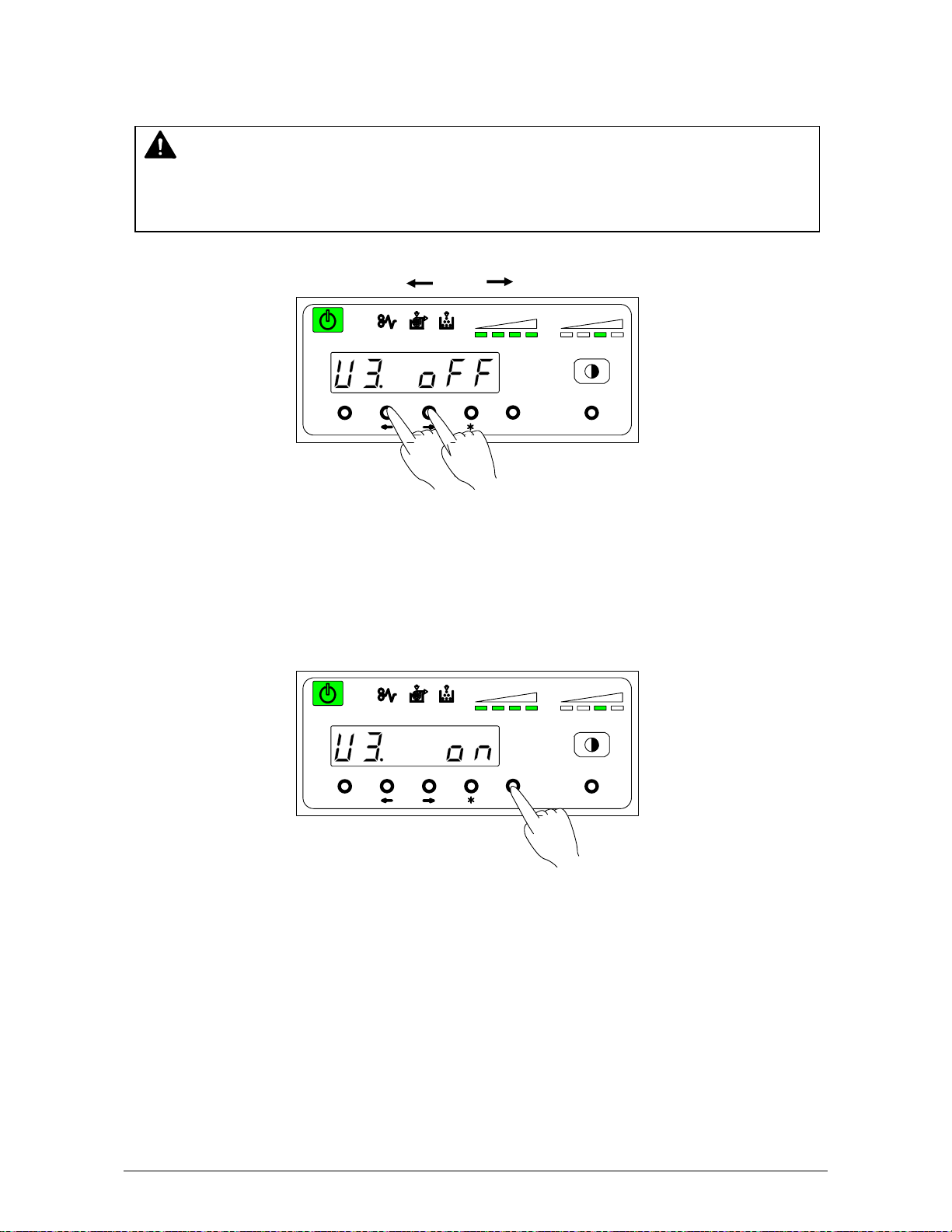
3. 3. 4 User Mode 3: Auto Power Off Setting Mode
This mode allows you to select Auto Power Off function.
NOTE
When “ON” is selected in this User Mode 3, the Auto Power OFF function can work obeying
the timer setting decided in the User Mode 2.
1) Select User Mode 3 “U3”, pressing [ ] or [ ] key.
U 3. o n : Auto Power Off function is selected.
U 3. o F F : Auto Power Off function is cancelled.
2) Press [Enter] key in order to make this function effective, then the selected setting is fixed.
(You can cancel this function with pressing [Enter] key again.)
job
TONER REMAI N IMAGE DENSITY
MENU ENTER T EST
job
TONER REMAI N IMAGE DENSITY
MENU ENTER T EST
Chapter 3 Advanced Operations 3-10
Page 49

3. 3. 5 User Mode 4: Cold Sleep Timer Setting Mode
This mode allows you to set Cold Sleep Timer.
Reference
The purpose of Cold Sleep Mode is to reduce the power consumption by shutting off to
supply the power to the heater unit.
It can save more power than Warm Sleep Mode.
The temperature of the heater unit is about 140 degrees centigrade when the Starprint 6000
is ready. But if no print job or copy job is sent for a long time, it is best for saving the power
to stop supplying the power to the heater unit completely.
The Cold Sleep Mode will be cancelled automatically if only you send a print job or a copy
job from the outer device.
However, please understand it takes a little long time to recover from the Cold Sleep Mode
because it is necessary to raise the temperature again up to about 140 degrees.
(Print does not start until the Starprint 6000 gets ready.)
Reference
When both the Cold Sleep Function and the Warm Sleep Function are effective, their
functions work as follows; (Both timers start simultaneously.)
As for the Warm Sleep Function, refer to page 3-14 to 3-16.
<Example 1>
In case that the Warm Sleep Timer sets 15 minutes and the Cold Sleep Timer sets 30
minutes, the printer will go into the warm sleep mode in 15 minutes after printing.
And the printer will go into the Cold Sleep Mode in 15 minutes after the printer goes into
the Warm Sleep Mode.
<Example 2>
In case that the Warm Sleep Timer sets 30 minutes and the Cold Sleep Timer sets 15
minutes, the printer will go into the Cold Sleep Mode in 15 minutes after printing.
In this case, the Warm Sleep Function is ineffective.
NOTE
To make this mode work, it is necessary to make the Cold Setting Mode (User Mode 5) ON.
(Refer to page 3-13)
Chapter 3 Advanced Operations 3-11
Page 50

1) Select User Mode 4 “U4”, pressing [ ] or [ ] key.
Then current setting timer is displayed.
job
TONER REMAI N IMAGE DENSITY
MENU ENTER TEST
2) Press [ * ] (increment) or [Enter] (decrement) key to select proper time, then the selected time
is fixed.
Timer is adjustable between 5 to 240 minutes (1 min. step).
job
TONER REMAI N IMAGE DENSITY
MENU ENTER TEST
Chapter 3 Advanced Operations 3-12
Page 51

3. 3. 6 User Mode 5: Cold Sleep Setting Mode
This mode allows you to select Cold Sleep function.
Reference
The purpose of Cold Sleep Mode is to reduce the power consumption by shutting off to
supply the power to the heater unit.
It can save more power than Warm Sleep Mode.
The temperature of the heater unit is about 140 degrees centigrade when the Starprint 6000
is ready. But if no print job or copy job is sent for a long time, it is best for saving the power
to stop supplying the power to the heater unit completely.
The Cold Sleep Mode will be cancelled automatically if only you send a print job or a copy
job from the outer device.
However, please understand it takes a little long time to recover from the Cold Sleep Mode
because it is necessary to raise the temperature again up to about 140 degrees.
(Print does not start until the Starprint 6000 gets ready.)
NOTE
When “ON” is selected in this User Mode 5, the Cold Sleep function can work obeying the
timer setting decided in the User Mode 4.
1) Select User Mode 5 “U5”, pressing [ ] or [ ] key.
job
TONER R EMAIN I MAGE DENSIT Y
MENU ENTER TEST
U 5. o n : Cold Sleep function is selected.
U 5. o F F : Cold Sleep function is cancelled.
2) Press [Enter] key in order to make this function effective, then the selected setting is fixed.
(You can cancel this function with pressing [Enter] key again.)
job
TONER R EMAIN I MAGE DENSIT Y
MENU ENTER TEST
Chapter 3 Advanced Operations 3-13
Page 52

3. 3. 7 User Mode 6: Warm Sleep Timer Setting Mode
This mode allows you to select Warm Sleep Timer.
Reference
The purpose of Warm Sleep Mode is to reduce the power consumption by falling down the
temperature of heater some degrees.
The temperature of the heater unit is about 140 degrees centigrade when the Starprint 6000
is ready. But if no print job or copy job is sent for a long time, it is better for saving the power
to fall down the temperature of heater. (Temperature is kept about 120 degrees centigrade.)
The Warm Sleep Mode will be cancelled automatically if only you send a print job or a copy
job from the outer device.
However, please understand it takes some minutes to recover from the Warm Sleep Mode
because it is necessary to raise the temperature again up to about 140 degrees.
(Print does not start until the Starprint 6000 gets ready.)
Reference
When both the Cold Sleep Function and the Warm Sleep Function are effective, their
functions work as follows; (Both timers start simultaneously.)
As for the Cold Sleep Function, refer to page 3-11 to 3-13.
<Example 1>
In case that the Warm Sleep Timer sets 15 minutes and the Cold Sleep Timer sets 30
minutes, the printer will go into the warm sleep mode in 15 minutes after printing.
And the printer will go into the Cold Sleep Mode in 15 minutes after the printer goes into
the Warm Sleep Mode.
<Example 2>
In case that the Warm Sleep Timer sets 30 minutes and the Cold Sleep Timer sets 15
minutes, the printer will go into the Cold Sleep Mode in 15 minutes after printing.
In this case, the Warm Sleep Function is ineffective.
NOTE
To make this mode work, it is necessary to make the Warm Sleep Setting Mode (User
Mode 7) ON. (Refer to page 3-16)
Chapter 3 Advanced Operations 3-14
Page 53
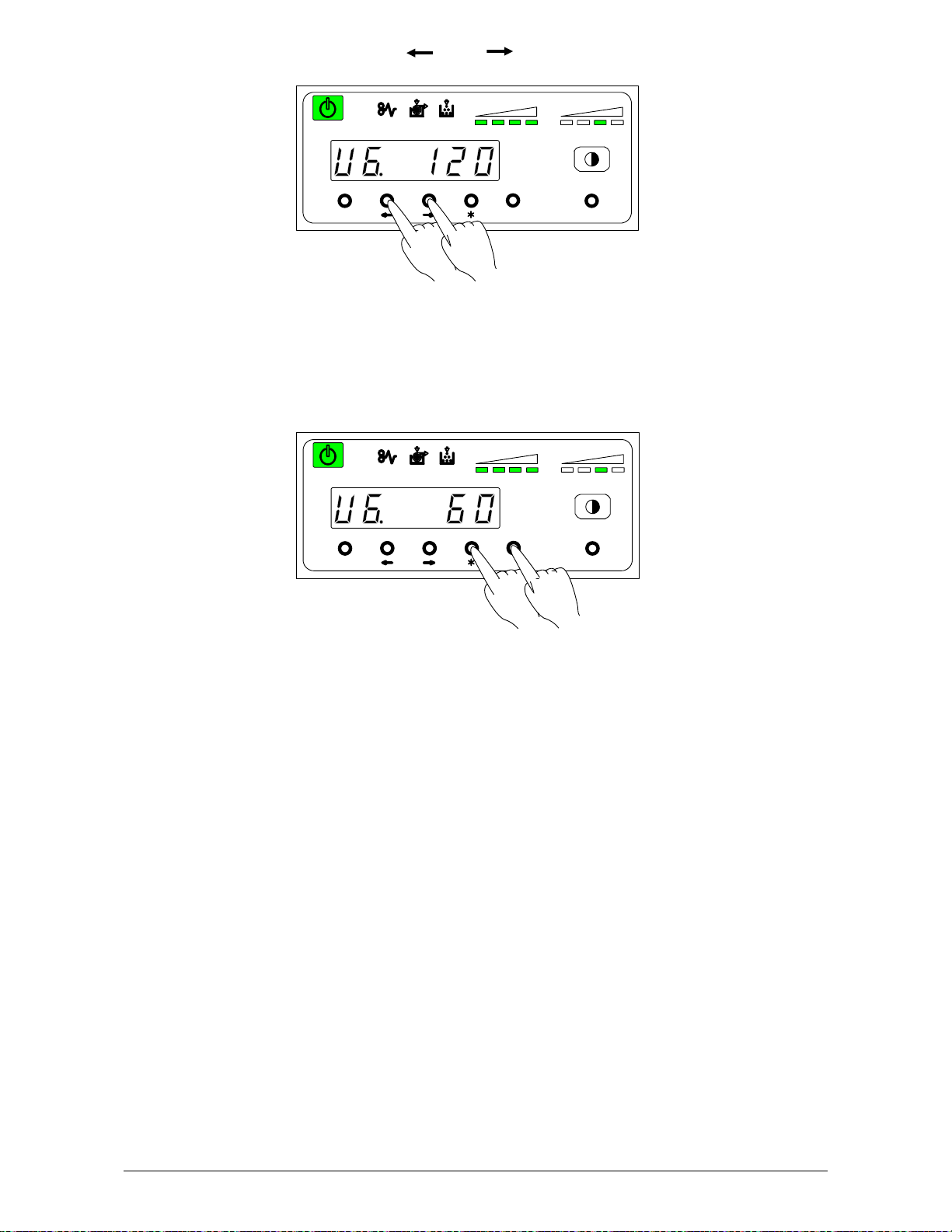
1) Select User Mode 6 “U6”, pressing [ ] or [ ] key.
Then current setting timer is displayed.
job
TONER REMAI N IMAGE DENSITY
MENU ENTER TEST
2) Press [ * ] (increment) or [Enter] (decrement) key to select proper time, then the selected time
is fixed.
Timer is adjustable between 5 to 240 minutes (1 min. step).
job
TONER R EMAIN I MAGE DENSIT Y
MENU ENTER TEST
Chapter 3 Advanced Operations 3-15
Page 54

3. 3. 8 User Mode 7: Warm Sleep Setting Mode
This mode allows you to select Warm Sleep function.
Reference
The purpose of Warm Sleep Mode is to reduce the power consumption by falling down the
temperature of heater some degrees.
The temperature of the heater unit is about 140 degrees centigrade when the Starprint 6000
is ready. But if no print job or copy job is sent for a long time, it is better for saving the power
to fall down the temperature of heater. (Temperature is kept about 120 degrees centigrade.)
The Warm Sleep Mode will be cancelled automatically if only you send a print job or a copy
job from the outer device.
However, please understand it takes some minutes to recover from the Warm Sleep Mode
because it is necessary to raise the temperature again up to about 140 degrees.
(Print does not start until the Starprint 6000 gets ready.)
NOTE
When “ON” is selected in this User Mode 7, the Warm Sleep function can work obeying the
timer setting decided in the User Mode 6.
1) Select User Mode 7 “U7”, pressing [ ] or [ ] key.
U 7. o n : Warm Sleep function is selected.
U 7. o F F : Warm Sleep function is cancelled.
2) Press [Enter] key in order to make this function effective then the selected setting is fixed.
(You can cancel this function with pressing [Enter] key again.)
job
TONER REMAI N IMAGE DENSITY
MENU ENTER TEST
job
TONER R EMAIN I MAGE DENSIT Y
MENU ENTER TEST
Chapter 3 Advanced Operations 3-16
Page 55
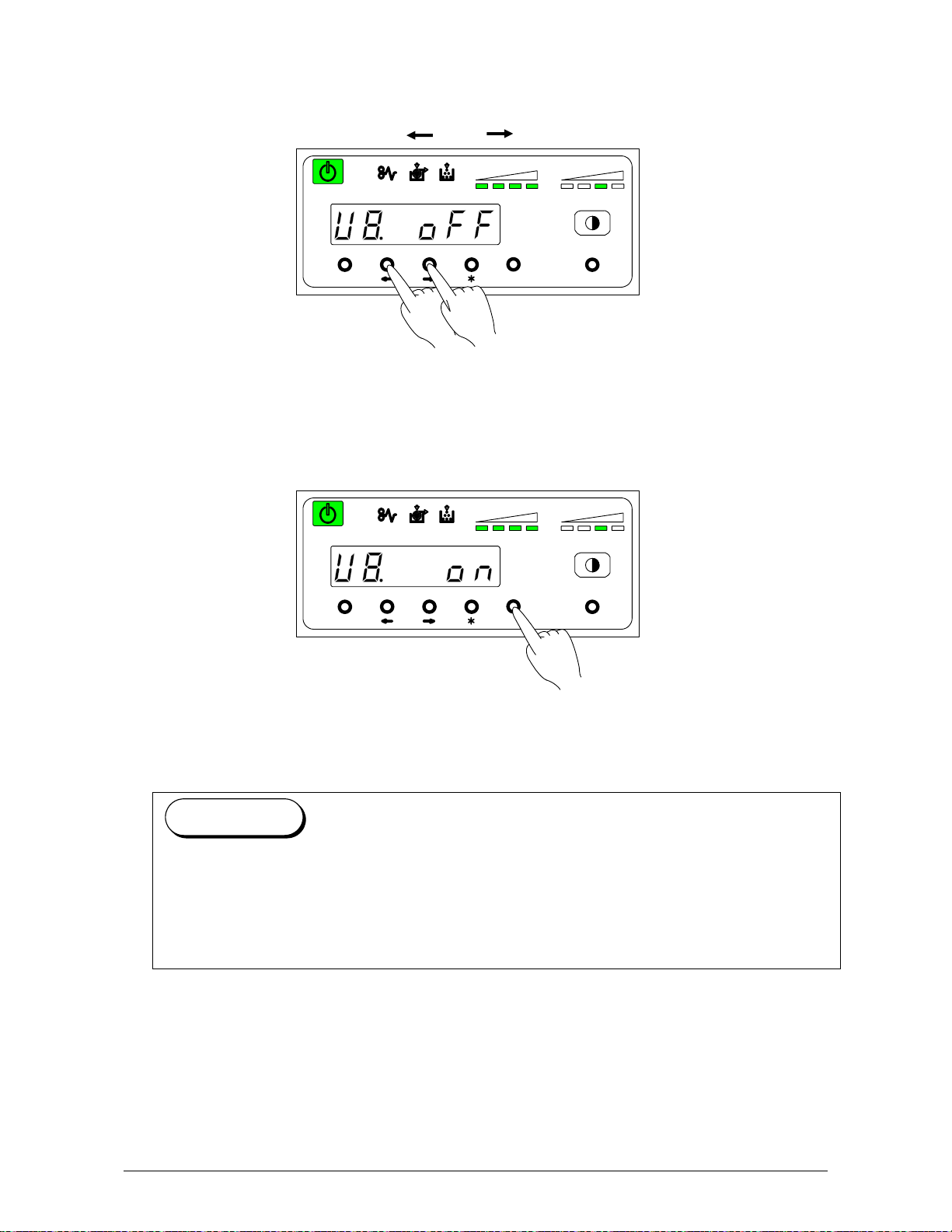
3. 3. 9 User Mode 8: Short Interval Setting Mode
This mode allows you to select function of Interval shortened.
1) Select User Mode 8 “U8”, pressing [ ] or [ ] key.
U 8. o n : Short Interval function is selected.
U 8. o F F : Short Interval function is cancelled. (Normal operation)
2) Press [Enter] key in order to make this function effective then the selected setting is fixed.
Reference
When this Short Interval Mode is selected, the interval between paper and next paper
become short. Therefore, print comes faster.
However, if “Image Area Expanded Mode” is selected at the same time, the possibility of
dirty image gets higher.
Even if “Image Area Expanded Mode” is not selected at the same time, dirty imgae might
happen due to improper adjustment of trailing edge margin.
job
TONER REMAI N I MAGE DENSI TY
MENU ENT ER TEST
job
TONER REMAI N I MAGE DENSI TY
MENU E NTER TEST
Chapter 3 Advanced Operations 3-17
Page 56

3. 3.10 User Mode 9: L/L Environment Setting Mode
If the wrinkling problem or fusing problem is found under the extreme environment of Low
Temperature / Low Humidity, set this User Mode 9.
Then the interval between papers becomes longer and print ratio becomes smaller.
A: In case continuous printing is done with 30” or wider roll, the interval between papers
becomes 6.5 seconds.
B: In case you select 22” or wider tracing roll, the interval between papers becomes 20 seconds
within the first 30 minutes in the morning after the printer turns to the ready condition.
1) Select User Mode 9 “U9”, pressing [ ] or [ ] key.
U 9. o n : Low Temperature / Low Humidity Environment Setting is selected.
U 9. o F F : Low Temperature / Low Humidity Environment Setting is cancelled.
(Normal operation)
2) Press [Enter] key in order to make this function effective then the selected setting is fixed.
(You can cancel this function with pressing [Enter] key again.)
job
TONER REMAI N IMAGE DENSITY
MENU ENTER TEST
job
TONER R EMAIN I MAGE DENSI TY
MENU ENT ER TEST
Chapter 3 Advanced Operations 3-18
Page 57

3. 3.11 User Mode A: H/H Environment Setting Mode
If the wrinkling problem is found under the extreme environment of High Temperature / High
Humidity, set this User Mode A.
When this mode is set, the waiting position of Roll 2 and Roll 4 changes much deeper position.
The first copy time gets longer, as a result.
Roll 1 Roll 2
Roll 3 Roll 4
1) Select User Mode A “UA”, pressing [ ] or [ ] key.
job
TONER REMAI N IMAGE DENSI TY
MENU ENTER TEST
U A. o n : H/H Environment Setting is selected.
U A. o F F : H/H Environment Setting is cancelled. (Normal operation)
2) Press [Enter] key in order to make this function effective then the selected setting is fixed.
(You can cancel this function with pressing [Enter] key again.)
job
TONER REMAIN IMAGE DENSITY
MENU ENTER TEST
Roll 1 Roll 2
Roll 3 Roll 4
Chapter 3 Advanced Operations 3-19
Page 58

Chapter 4
Error Indications and Correction
Page
4.1 Paper Mis-feed Errors 4- 2
4.1.1 Paper mis-feed in Roll Deck Section (J-01, J-02, J-03 and J-04) 4- 3
4.1.2 Paper mis-feed in Manual Feeder Section (J-05) 4- 5
4.1.3 Paper mis-feed in Paper Feeder Section (J-10, J-11 and J-12) 4- 6
4.1.4 Paper mis-feed in Fuser Section (J-13 and J-14) 4- 8
4.2 Open Cover Errors 4-11
4.2.1 Roll Deck Open (U-01, U-02 and U-03) 4-11
4.2.2 Lever / Toner Cover Open (U-05) 4-12
4.2.3 Exit Cover Open (U-06) 4-13
4.3 Other Errors 4-14
4.3.1 Toner Low 4-14
4.3.2 Roll Empty 4-15
4.3.3 No Manual Paper 4-16
4.4 Call Service Errors 4-17
Chapter 4 Error Indications and
Correction
4-1
Page 59
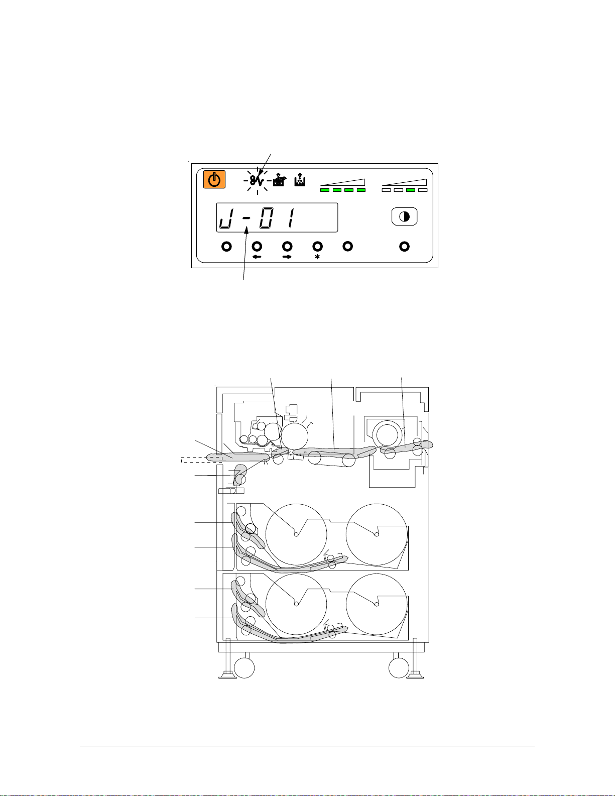
4. 1 Paper Mis-feed Errors
If a paper mis-feed occurs, the Paper Mis-feed Indicator on the Operation Panel lights to inform
you of the error.
The Operation Panel also indicates a mis-feed code ( J-XX ) to let you know where the paper is
mis-fed.
Example : J-01 (Paper mis-feed in the Roll 1)
Please check where the paper mis-feed has occurred referring to the following diagram.
(Greater detail on each code are on the following pages.)
J- 0 5
J- 1 0
J- 0 1
J- 0 2
J- 0 3
J- 0 4
Paper Mis- feed Indicator
job
TONER REMAIN IMAGE DENSITY
MENU ENT ER TEST
Paper Jam Code
J-11 J-12 J- 13,J- 14
Chapter 4 Error Indications and
4-2
Correction
Page 60

4. 1. 1 Paper mis-feed in Roll Deck Section
2
(J-01, J-02, J-03 and J-04)
When a paper mis-feed occurs in a Roll Deck, the Operation Panel indicates a “J-01”, “J-02”,
“J-03” or “J-04”.
J-01 : In the Roll 1
J-02 : In the Roll 2
J-03 : In the Roll 3 (Upper Cassette in case of option)
J-04 : In the Roll 4 (Lower Cassette in case of option)
J- 0 1
J- 0 2
Roll 1 Roll
(Example : Roll 1)
J- 0 3
J- 0 4
Roll 3 Roll 4
Clear the mis-feed using the following procedure:
1) Open the Roll Deck in issue. And then rewind the roll onto the media core.
job
TONER REMAI N IMAGE DEN SITY
MENU ENT ER TEST
Chapter 4 Error Indications and
4-3
Correction
Page 61

2) If the leading edge of the media is torn or folded, straighten (cut).
3) Set the roll media correctly.
4) Close the Roll Deck.
Chapter 4 Error Indications and
Correction
4-4
Page 62
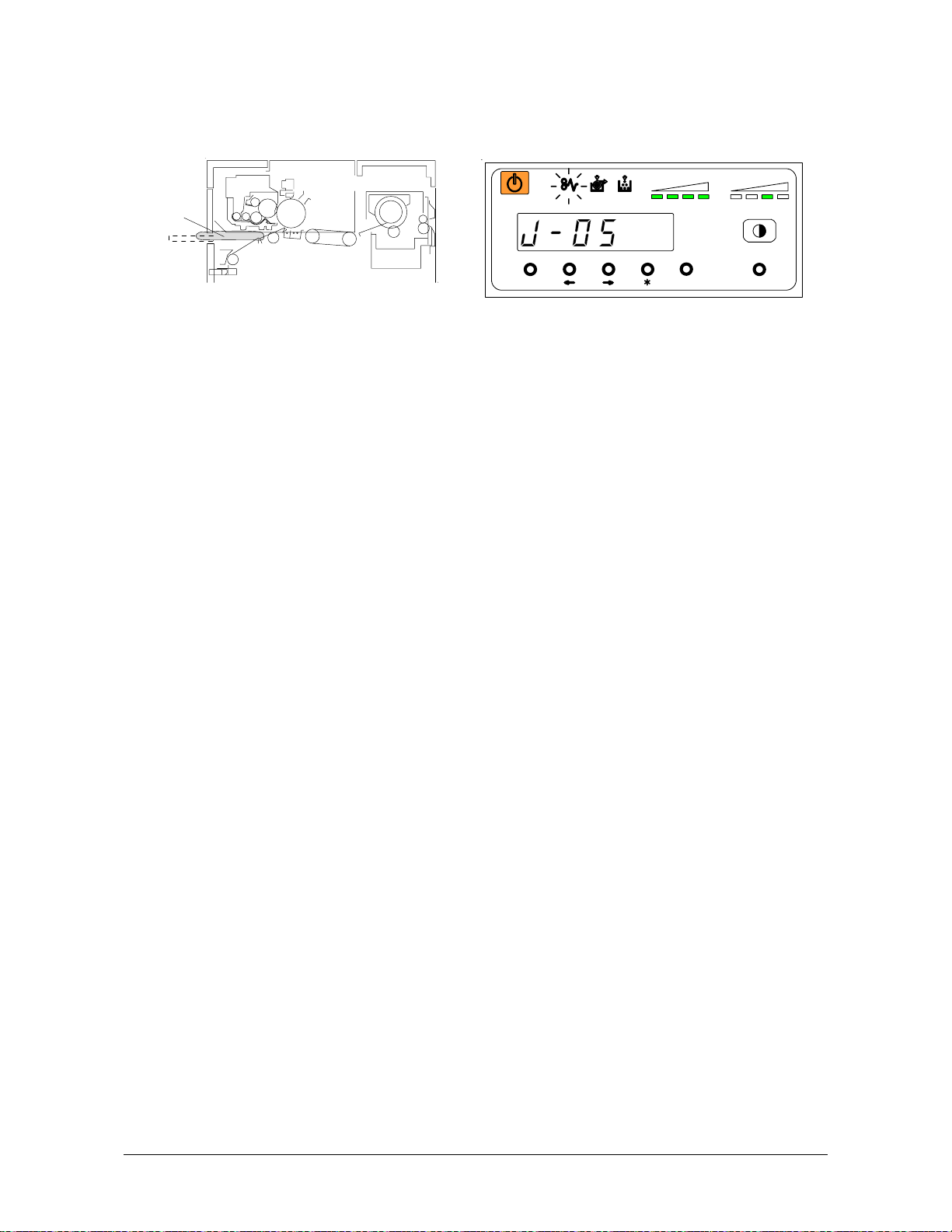
4. 1. 2 Paper mis-feed in Manual Feeder Section (J-05)
When a paper mis-feed occurs in a Manual Feeder, the Operation Panel indicates a “J-05”.
J- 0 5
Clear the mis-feed using the following procedure:
1) Pull the mis-feed paper, and if the leading edge of the paper is torn or folded, replace to the
new one.
job
TONER REMAIN I MAGE DENSITY
MENU ENTER TEST
Chapter 4 Error Indications and
4-5
Correction
Page 63
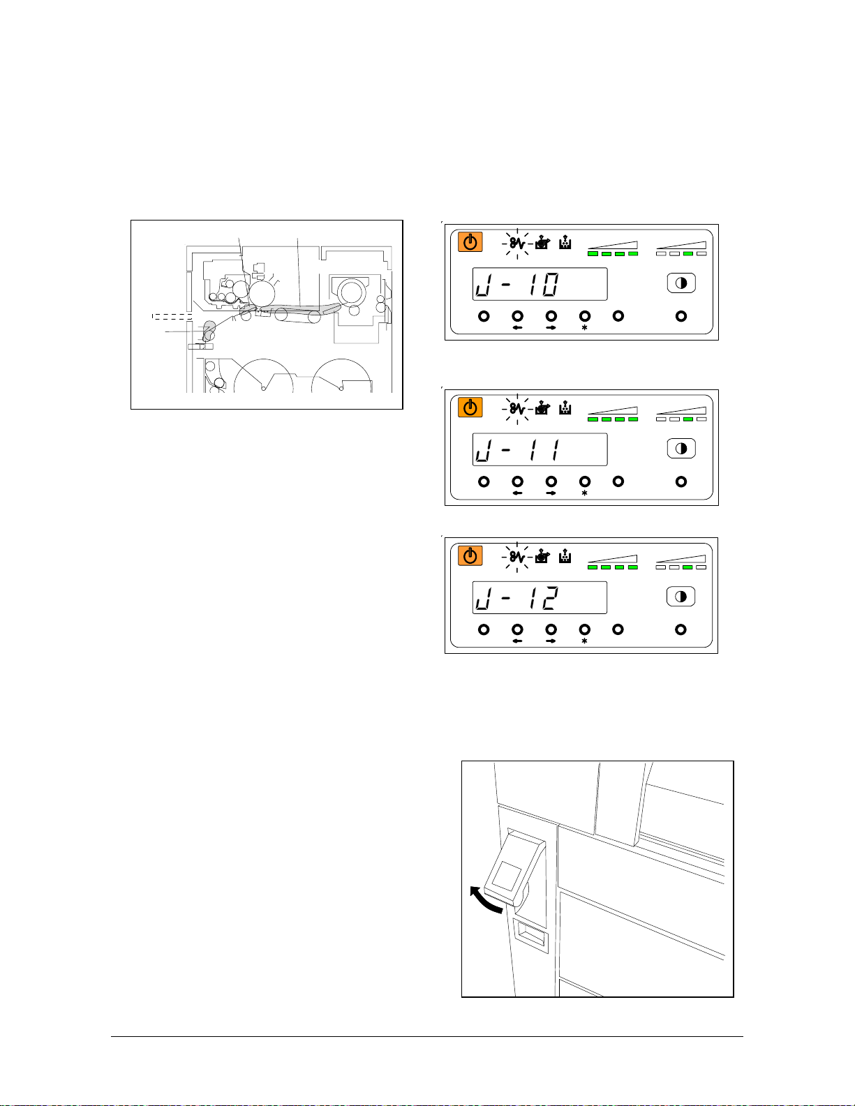
4. 1. 3 Paper mis-feed in Paper Feed Section
(J-10, J-11 and J-12)
When a paper mis-feed occurs in a Paper Feed Section, Operation Panel indicates a “J-10”,
“J-11” or “J-12”.
J-10 : In the Cutter Section
J-11 : In the Gate Roller Section
J-12 : In the Separation Section
J- 1 0
Clear the mis-feed using the following procedure:
1) Lift up the Lever of the Internal Transportation Unit.
J-11 J-12
job
TONER REMAIN I MAGE DENSITY
MENU ENTER TEST
job
TONER REMAIN I MAGE DENSITY
MENU ENTER TEST
job
TONER REMAIN IMAGE DENSIT Y
MENU EN TER T EST
Chapter 4 Error Indications and
4-6
Correction
Page 64

2) Open the Manual Table.
3) Pull out the Upper Frame Unit to your side.
4) Remove the jammed paper.
5) Push back the Upper Frame Unit.
6) Close the Manual Table.
7) Push down the Lever of the Internal
Transportation Unit.
Chapter 4 Error Indications and
Correction
4-7
Page 65

4. 1. 4 Paper mis-feed in Fuser Section (J-13 and J-14)
When a paper mis-feed occurs in the Fuser Section, the Operation Panel indicates either a “J-13”
or a “J-14”.
Clear the mis-feed using the following procedure:
1) Open the Exit Cover holding two handles.
WARNING
There are extremely hot parts inside the Heater Unit.
Do not touch any parts in the Heater Unit, or you will be burnt.
Also the mis-feed media can be very hot.
Be careful not to get burnt, when you remove it.
2) If it is possible to access the jammed paper, pull out the jammed paper backward gently.
J- 1 3 J- 1 4
job
TONER REMAIN IMAGE DENSIT Y
MENU EN TER TE ST
job
TONER REMAIN I MAGE DENSITY
MENU ENTER TEST
Chapter 4 Error Indications and
4-8
Correction
Page 66

Be careful not to tear the jammed paper.
3) If it is not possible to access the jammed paper
from the rear side, lift up the Lever of the Internal
Transportation Unit.
4) Open the Manual Table.
Chapter 4 Error Indications and
Correction
4-9
Page 67

5) Pull out the Upper Frame Unit to your side.
6) Remove the jammed paper.
7) Push back the Upper Frame Unit.
8) Close the Manual Table.
9) Push down the Lever of the Internal
Transportation Unit.
10) Rewind the jammed Roll manually.
Chapter 4 Error Indications and
Correction
4-10
Page 68

4. 2 Open Cover Errors
The Operation Panel will indicate an error code (U-XX) if there are any open decks or open covers.
Close each deck (or cover) as it is not possible to print, if this error exists.
4. 2. 1 Roll Deck Open (U-01, U-02 and U-03)
The corresponding Roll Deck is opened when the Operation Panel indicates a “U-01”, “U-02” or
“U-03”.
U-01 : Upper Roll Deck is opened.
U-02 : Lower Roll Deck is opened. (Upper Cassette is opened in case of option)
U-03 : Lower Cassette is opened in case of option.
(Example : Upper Roll Deck is opened.)
Firmly push the Roll Deck close.
NOTE
This error code will be indicated if the Roll Deck is not locked correctly, although it may look
closed.
Open and close the Roll Deck again, pushing until locked. Ensure both sides of the roll deck
are in their correct position.
No Good
(Not Locked)
job
TONER RE MAIN IMAGE DENSIT Y
MENU ENTER TEST
Good
Chapter 4 Error Indications and
4-11
Correction
Page 69

4. 2. 2 Lever / Toner Cover Open (U-05)
When either the Lever or the Toner Cover is opened the Operation Panel indicates a “U-05”.
Check the Lever and push the Lever firmly, or check the Toner Cover if it is opened.
job
TONER R EMAIN IMAGE DENSITY
MENU ENTER TEST
Chapter 4 Error Indications and
4-12
Correction
Page 70

4. 2. 3 Exit Cover Open (U-06)
When the Exit Cover is opened, the Operation Panel indicates a “U-06”.
Close the Exit Cover.
job
TONER RE MAIN IMAGE DENSIT Y
MENU ENTER TEST
Chapter 4 Error Indications and
4-13
Correction
Page 71

4. 3 Other Errors
4. 3. 1 Toner Low
The machine indicates a “Toner Low” by lighting the Toner Low Indicator on the Operation Panel.
Toner Cartridge replacement is required.
However, if this indicator flashes, it means that this machine is in the down sequence caused by
toner consumption. Therefore, it is not necessary to replace the Toner Cartridge, yet.
Refer to [2. 4 Installing Toner] on page 2-13.
MENU ENTER TEST
Toner Low Indicator
job
TONER REMAIN IMAGE DENSITY
Chapter 4 Error Indications and
4-14
Correction
Page 72

4. 3. 2 Roll Empty
The machine indicates a “Roll Empty” by lighting the Roll Empty Indicator on the Operation Panel
if the roll media currently in use is consumed during printing.
Installation of a new roll is required.
Refer to [2.3 Installing Roll Media into a Roll Deck] on page 2-5.
MENU ENTER TEST
Roll Empty Indicator
job
TONER REMAIN IMAGE DENSI TY
Chapter 4 Error Indications and
4-15
Correction
Page 73
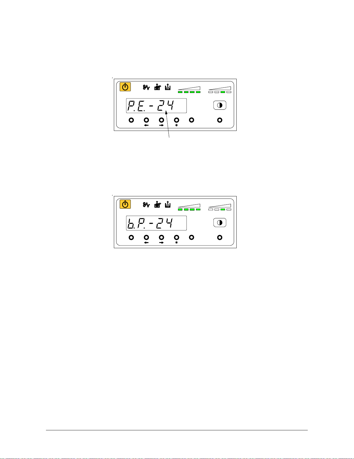
4. 3. 3 No Manual Paper
The machine indicates a “Paper Empty” on Display.
Insertion of an indicated size of paper is required.
[Roll Selector] changes the Roll Deck. ( Refer to page 2-11 )
1 Æ 2 Æ 3 Æ 4 Æ Manual (no LEDs turn on).
When the Manual Paper is inserted, indication is changed from [P.E.] to [b.p.].
job
TONER REMAIN IMAGE DENSITY
MENU ENTER TEST
Required paper size
job
TONER REMAIN IMAGE DENSITY
MENU ENTER TEST
Chapter 4 Error Indications and
4-16
Correction
Page 74
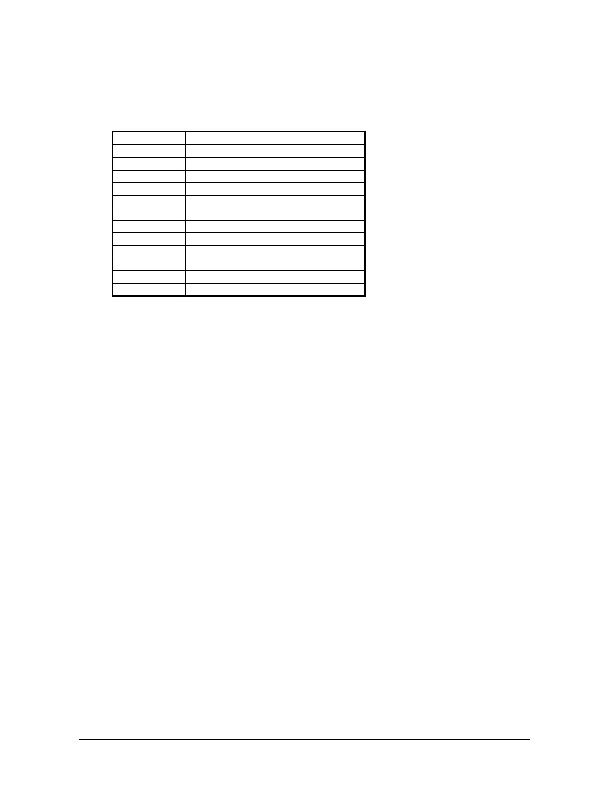
4. 4 Call Service Errors
You will note one of the following error codes on the Operation panel if the machine has a fatal
Error.
It is impossible for the user to cure these errors to resolve these issues.
PLEASE CALL YOUR TRAINED SERVICE PERSONNEL TO RESOLVE THESE ERRORS.
Error Code Name of the error
E - 01 Fuser Temperature Rising Error
E - 02 Fuser Over Temperature Error
E - 04 Developer Error
E - 06 Counter Error
E - 07 Cutter Error
E - 14 Fuser Motor Error
E - 16 Wire Cleaning Error
E - 21 Fuser Thermostat Error
E - 40 Folder Error
E - 41 Key Card Error
E - 50 Cassette Lift Error
E - 51 High Voltage Power Error
If one of the above errors is displayed:
1) Turn off the printer, wait approximately 30 seconds, and then turn on the printer again.
2) If the same error code is displayed, turn off the printer, and then unplug the printer from the wall
outlet.
Call your service personnel.
Chapter 4 Error Indications and
Correction
4-17
 Loading...