

Page 1

SERVICE MANUAL
Models
ST-723/724
FEBRUARY 1999
CSM-ST723/724
KONICA BUSINESS TECHNOLOGIES, INC.
Page 2

Page 3

ST-723/724
SERVICE MANUAL
FEBRUARY 1999
Used on Konica Model
7823
Page 4

IMPORTANT NOTICE
Because of the possible hazards to an inexperienced
person servicing this equipment, as well as the risk of
damage to the equipment, Konica Business Technologies strongly recommends that all servicing be performed by Konica-trained service technicians only.
Changes may have been made to this equipment to
improve its performance after this service manual was
printed. Accordingly, Konica Business Technologies,
Inc., makes no representations or warranties, either
expressed or implied, that the information contained in
this service manual is complete or accurate. It is understood that the user of this manual must assume all risks
or personal injury and/or damage to the equipment while
servicing the equipment for which this service manual
is intended.
Corporate Publications Department
© 2001, KONICA BUSINESS TECHNOLOGIES, INC.
All rights reserved.
Printed in U.S.A.
Page 5

CONTENTS
GENERAL, MECHANICAL/ELECTRICAL
1. SPECIFICATIONS. . . . . . . . . . . . . . . . . . . . . . . . . . . . . . . . . . . . . . M-1
2. PARTS IDENTIFICATION. . . . . . . . . . . . . . . . . . . . . . . . . . . . . . . . M-2
3. CROSS-SECTIONAL VIEW . . . . . . . . . . . . . . . . . . . . . . . . . . . . . . M-3
4. DRIVE SYSTEM . . . . . . . . . . . . . . . . . . . . . . . . . . . . . . . . . . . . . . . M-4
5. ELECTRICAL COMPONENTS LAYOUT. . . . . . . . . . . . . . . . . . . . M-5
6. OUTLINE OF OPERATION IN EACH MODE
6-1. INITIAL OPERATION. . . . . . . . . . . . . . . . . . . . . . . . . . . . . . . . M-6
6-2. NON-SORT MODE . . . . . . . . . . . . . . . . . . . . . . . . . . . . . . . . . M-6
6-3. SORT MODE . . . . . . . . . . . . . . . . . . . . . . . . . . . . . . . . . . . . . . M-7
6-4. GROUP MODE. . . . . . . . . . . . . . . . . . . . . . . . . . . . . . . . . . . . . M-9
6-5. SORT STAPLE MODE. . . . . . . . . . . . . . . . . . . . . . . . . . . . . . . M-10
6-6. MANUAL STAPLE MODE . . . . . . . . . . . . . . . . . . . . . . . . . . . . M-11
6-7. BIN MOVEMENT AT END OF COPY CYCLE . . . . . . . . . . . . M-11
7. OPERATION OF EACH MECHANISM
7-1. PAPER TRANSPORT MECHANISM . . . . . . . . . . . . . . . . . . . M-12
7-2. PAPER ALIGNING MECHANISM. . . . . . . . . . . . . . . . . . . . . . M-13
7-3. BIN MOVING MECHANISM . . . . . . . . . . . . . . . . . . . . . . . . . . M-17
7-4. PAPER CLAMPING MECHANISM . . . . . . . . . . . . . . . . . . . . . M-21
7-5. PAPER DETECTION AT STAPLING MECHANISM . . . . . . . M-25
7-6. STAPLING MECHANISM . . . . . . . . . . . . . . . . . . . . . . . . . . . . M-25
7-7. SORTER SET SWITCH. . . . . . . . . . . . . . . . . . . . . . . . . . . . . . M-35
7-8. BIN EMPTY DETECTION . . . . . . . . . . . . . . . . . . . . . . . . . . . . M-36
8. OPERATION IN EACH MODE
8-1. NON-SORT MODE . . . . . . . . . . . . . . . . . . . . . . . . . . . . . . . . . M-37
8-2. SORT MODE . . . . . . . . . . . . . . . . . . . . . . . . . . . . . . . . . . . . . . M-38
8-3. GROUP MODE. . . . . . . . . . . . . . . . . . . . . . . . . . . . . . . . . . . . . M-40
8-4. SORT STAPLE MODE. . . . . . . . . . . . . . . . . . . . . . . . . . . . . . . M-42
iii
Page 6

CONTENTS
. . . . . . . . . . . . . . . . . . . . . . . . . . . . . . . . . . . . . . . . . . . . . . . . . . . . . . . . . S-1
TEST MODE
DIS/REASSEMBLY, ADJUSTMENT
1. DISASSEMBLY/REASSEMBLY
1-1. REMOVAL OF EXTERIOR COVERS. . . . . . . . . . . . . . . . . . . D-1
1-2. REMOVAL OF THE TRANSPORT GUIDE PLATE ASSY . . D-2
1-3. REMOVAL OF THE BIN MOVING MOTOR M1 UNIT . . . . . . D-3
1-4. REMOVAL OF PAPER CLAMP SOLENOID SL1 . . . . . . . . . D-4
1-5. REMOVAL OF THE STAPLE UNIT . . . . . . . . . . . . . . . . . . . . D-4
1-6. REMOVAL OF THE SORTER LOCK RELEASE LEVER . . . D-5
1-7. REMOVAL OF THE BINS . . . . . . . . . . . . . . . . . . . . . . . . . . . . D-6
2. ADJUSTMENTS. . . . . . . . . . . . . . . . . . . . . . . . . . . . . . . . . . . . . . . . D-9
TROUBLESHOOTING
1. MISFEED DETECTION/TROUBLESHOOTING
PROCEDURES
1-1. MISFEED DETECTION . . . . . . . . . . . . . . . . . . . . . . . . . . . . . . T-1
1-2. TROUBLESHOOTING PROCEDURES . . . . . . . . . . . . . . . . . T-1
2. MALFUNCTION DETECTION/TROUBLESHOOTING
PROCEDURES
2-1. MALFUNCTION DETECTION. . . . . . . . . . . . . . . . . . . . . . . . . T-3
2-2. TROUBLESHOOTING PROCEDURES . . . . . . . . . . . . . . . . . T-5
◆ELECTRICAL WIRING DIAGRAM
◆ELECTRICAL CIRCUIT DIAGRAM
iv
Page 7

SAFETY PRECAUTIONS
SAFETY PRECAUTIONS
Installation Environment
Safety considerations usually are directed toward
machine design and the possibility of human error. In
addition, the environment in which a machine is operated must not be overlooked as a potential safety
hazard.
Most electrical equipment is safe when installed in a
normal environment. However, if the environment is
different from what most people consider to be normal, it is conceivable that the combination of the
machine and the room air could present a hazardous
combination. This is because heat (such as from
fusing units) and electrical arcs (which can occur
inside switches) have the ability to ignite flammable
substances, including air.
When installing a machine, check to see if there
is anything nearby which suggests that a poten-
tial hazard might exist. For example, a laboratory
might use organic compounds which, when they
evaporate, make the room air volatile. Potentially dangerous conditions might be seen or smelled. The
presence of substances such as cleaners, paint thinners, gasoline, alcohol, solvents, explosives, or similar items should be cause for concern.
If conditions such as these exist, take appropriate
action, such as one of the following suggestions.
effect may be caused by altering any aspect of the
machine’s design. Such changes have the potential
of degrading product performance and reducing
safety margins.
For these reasons, installation of any modification not
specifically authorized by Konica Business Machines
U.S.A., Inc., is strictly prohibited.
The following list of prohibited actions is not all-inclusive, but demonstrates the intent of this policy.
• Using an extension cord or any unauthorized
power cord adapter.
• Installing any fuse whose rating and physical size
differs from that originally installed.
• Using wire, paper clips, solder, etc., to replace or
eliminate any fuse (including temperature fuses).
• Removing (except for replacement) any air filter.
• Defeating the operation of relays by any means
(such as wedging paper between contacts).
• Causing the machine to operate in a fashion other
than as it was designed.
• Making any change which might have a chance
of defeating built-in safety features.
• Using any unspecified replacement parts.
• Determine that the environment is controlled
(such as through the use of an exhaust hood) so
that an offending substance or its fumes cannot
reach the machine.
• Remove the offending substance.
• Install the machine in a different location.
The specific remedy will vary from site to site, but the
principles remain the same. To avoid the risk of injury
or damage, be alert for changes in the environment
when performing subsequent service on any machine, and take appropriate action.
Unauthorized Modifications
Konica copiers have gained a reputation for being
reliable products. This has been attained by a combination of outstanding design and a knowledgeable
service force.
The design of the copier is extremely important. It is
the design process that determines tolerances and
safety margins for mechanical, electrical, and electronic aspects. It is not reasonable to expect individuals not involved in product engineering to know what
General Safety Guidelines
This copier has been examined in accordance with
the laws pertaining to various product safety regulations prior to leaving the manufacturing facility to
protect the operators and service personnel from
injury. However, as with any operating device, components will break down through the wear-and-tear of
everyday use, as will additional safety discrepancies
be discovered. For this reason, it is important that the
technician periodically performs safety checks on the
copier to maintain optimum reliability and safety.
The following checks, not all-inclusive, should be
made during each service call:
CAUTION: Avoid injury. Ensure that the copier is
disconnected from its power source before continuing.
• Look for sharp edges, burrs, and damage on all
external covers and copier frame.
• Inspect all cover hinges for wear (loose or broken).
• Inspect cables for wear, frays, or pinched areas.
v
Page 8

SAFETY PRECAUTIONS
• Ensure that the power cord insulation is not damaged (no exposed electrical conductors).
• Ensure that the power cord is properly mounted
to the frame by cord clamps.
• Check the continuity from the round lug (GND) of
the power cord to the frame of the copier -- ensure
continuity. An improperly grounded machine can
cause an electrically-charged machine frame.
Safeguards During Service Calls
Confirm that all screws, parts, and wiring which are
removed during maintenance are installed in their
original positions.
• When disconnecting connectors, do not pull the
wiring, particularly on AC line wiring and high
voltage parts.
• Do not route the power cord where it is likely to
be stepped on or crushed.
• Carefully remove all toner and dirt adhering to any
electrical units or electrodes.
• After part replacement or repair work, route the
wiring in such a way that it does not contact any
burrs or sharp edges.
• Do not make any adjustments outside of the
specified range.
Applying Isopropyl Alcohol
Care should be exercised when using isopropyl alcohol, due to its flammability. When using alcohol to
clean parts, observe the following precautions:
• Remove power from the equipment.
• Use alcohol in small quantities to avoid spillage
or puddling. Any spillage should be cleaned up
with rags and disposed of properly.
• Be sure that there is adequate ventilation.
• Allow a surface which has been in contact with
alcohol to dry for a few minutes to ensure that the
alcohol has evaporated completely before applying power or installing covers.
Summary
It is the responsibility of every technician to use professional skills when servicing Konica products. There
are no short cuts to high-quality service. Each copier
must be thoroughly inspected with respect to safety
considerations as part of every routine service call.
The operability of the copier, and more importantly,
the safety of those who operate or service the copier,
are directly dependent upon the conscientious effort
of each and every technician.
Remember...when performing service calls, use good
judgement (have a watchful eye) to identify safety
hazards or potential safety hazards that may be present, and correct these problem areas as they are
identified -- the safety of those who operate the copier
as well as those who service the copier depend on it!
vi
Page 9

GENERAL,
MECHANICAL/
ELECTRICAL
Page 10

Page 11

SPECIFICATIONS
1
Type : 10-Moving-Bin Sorter (ST-723)
10-Moving-Bin Sorter with Automatic Stapler (ST-724)
Installation : Appendant to copier
No. of Bins : 11
Modes : Non-Sort
Sort
Group
Sort Staple ST-724 only
*1
*2
Manual Staple ST-724 only
*1: Not available for an ST-724 mounted together with
an DF-723.
*2: Available only for a system equipped also with an
DF-723.
In the Non-Sort Mode
Copy Medium : Recommended paper weighing 60 to 90 g/m
24 lbs., translucent paper, transparencies, heavy paper
(91 to 157 g/m
2
or 25 to 41 lbs.).
Size : A5 lengthwise to A3, and A3 Wide or 5-1/2"
× 17" and Full Bleed
Max. Capacity : Recommended paper : 1st Bin - 50
11"
(80 g/m
2
or 22 lb.) : 2nd to 10th Bin - 25/Bin
: Transparencies: 10 (max. size: A4 or 8-1/2"
: Other special paper: 10
2
or 16 to
× 8-1/2" to
× 11")
In the Sort/Group Mode
Copy Medium : Recommended paper weighing 60 to 80 g/m
2
or 16 to
22 lbs.
Size : A5 lengthwise to A3, 5-1/2"
Max. Capacity : 25 sheets of 80 g/m
In the Sort Staple Mode
Copy Medium : Recommended paper weighing 60 to 80 g/m
× 8-1/2" to 11" × 17"
2
or 22 lb. paper per Bin
2
or 16 to
22 lbs.
Size : A4 to A3, 8-1/2"
Max. Capacity : 25 sheets of 80 g/m
No. of Copies That Can
: 2 to 25 copies of 80 g/m
× 11" to 11" × 17"
2
or 22 lb. paper per Bin
2
or 22 lb. paper
be Stapled
Power Requirement : DC24V (supplied from copier)
Power Consumption : 72W or less
Dimensions : Width - 400 mm or 15-3/4"
Depth - 562 mm or 22-1/4"
Height - 404 mm or 16"
Weight : ST-723 - 15.8 kg or 34-3/4 lbs. (excl. Mounting Bracket)
ST-724 - 18.1 kg or 40 lbs. (excl. Mounting Bracket)
Environmental
: Same as copier
Requirements
M-1
Page 12
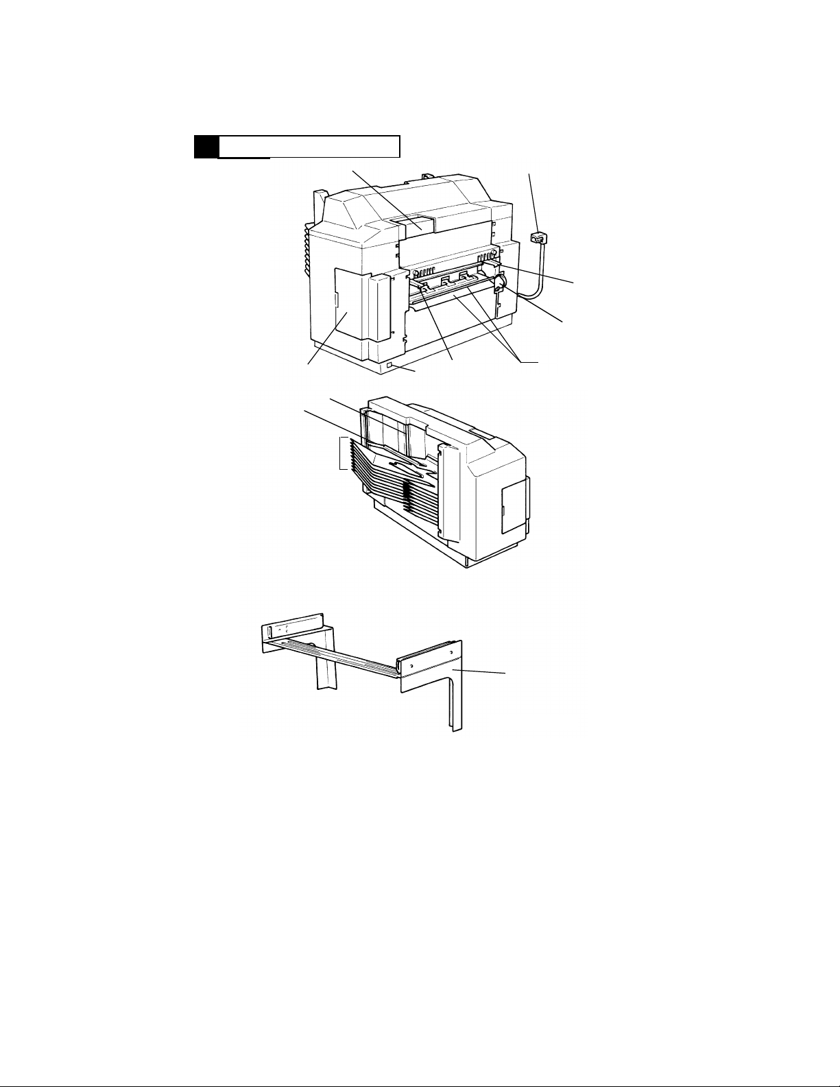
PARTS IDENTIFICATION
2
1
2
3
4
7
10
9
8
1. Sorter Lock Release Lever
2. Hookup Connector
3. Sorter Lock Lever
4. Drive Coupling Gear
5. Transport Guide Plates
6. Sorter Set Detector
7. Stapler Cover
(Cannot be opened on ST-723)
3
6
4428M060AA
11
4428M061AA
8. 1st to 10th Bins
9. Top Bin
10. Paper Aligning Bar
(ST-724 only)
11. Mounting Bracket
5
M-2
Page 13
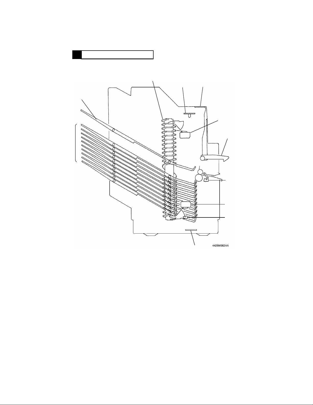
CROSS-SECTIONAL VIEW
3
3
4
2
1
5
6
7
8
9
10
1. 1st to 10th Bins
2. Top Bin
3. Spiral Cam
4. Bin Empty Sensor LED Board
PWB-B
5. Sorter Lock Release Lever
6. Bin Upper Limit Interlock
Switch S1
11
7. Sorter Lock Lever
8. Sorter Exit Sensor PC2
9. Bin Lower Limit Interlock
Switch S2
10. Bin Lower Limit Position
Sensor PC4
11. Bin Empty Sensor PQ Board
PWB-C
M-3
Page 14
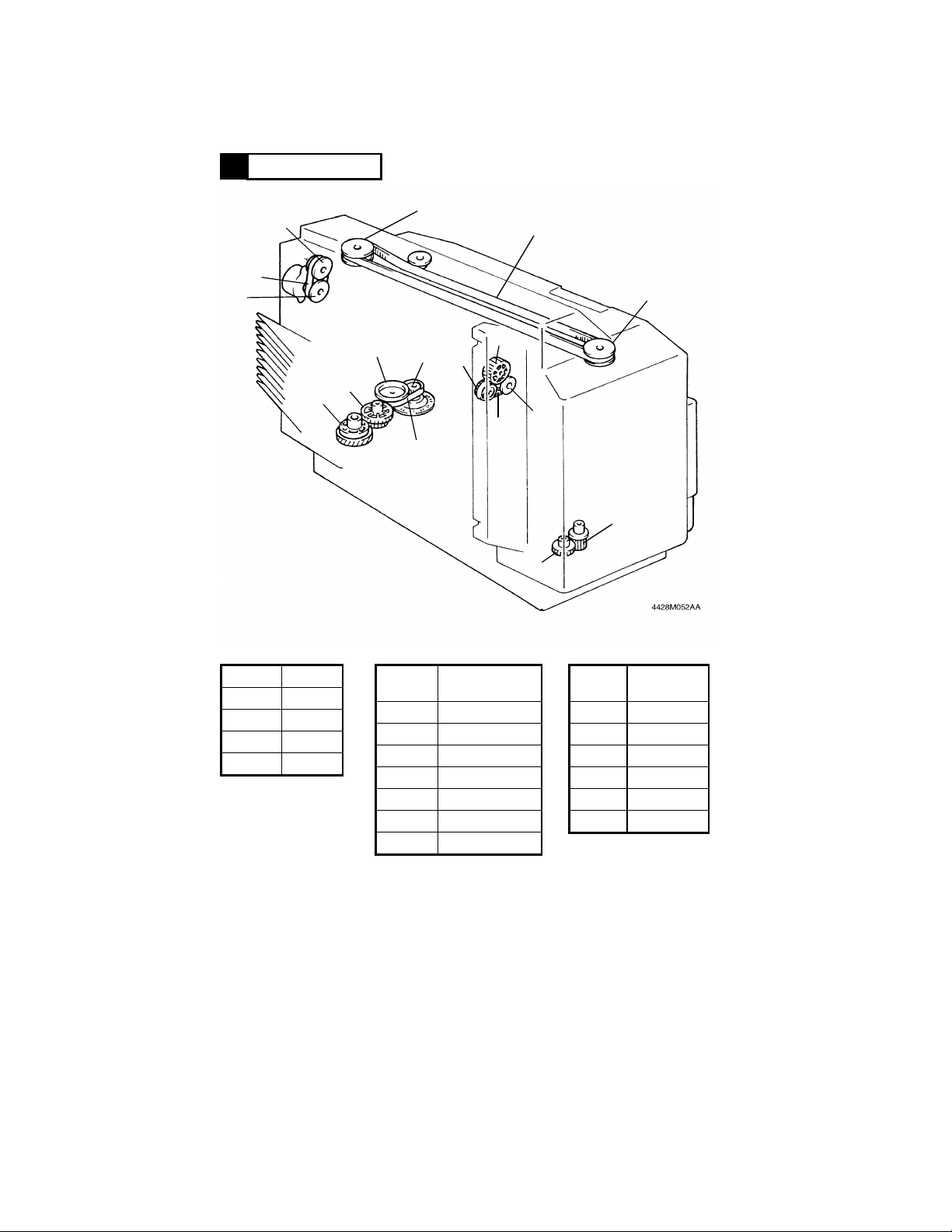
DRIVE SYSTEM
4
Belt 1
P1
P2
G3
G4
GP1
P5
Belt 3
P3
P6
G5
Belt 4
Belt 2
P4
GP2
G1
G2
Symbol Length
Belt 1 150 mm
Belt 2 918 mm
Belt 3 160 mm
Belt 4 150 mm
Symbol
G1 25/15
G2 36
G3 37
G4 34/16
G5 30
GP1 12/60
GP2 23/19
Gear/Pulley:
No. of Teeth
M-4
Symbol
Pulley: No.
of Teeth
P1 22
P2 22
P3 28
P4 28
P5 20
P6 20
Page 15
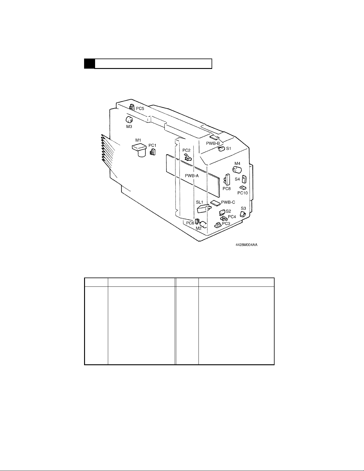
ELECTRICAL COMPONENTS LAYOUT
5
SYMBOL PARTS NAME SYMBOL PARTS NAME
PWB-A
PWB-B
PWB-C
M1
∗M2
∗M3
∗M4
∗SL1
PC1
PC2
PC3
PC4
∗ ... ST-724 Only
Control Board
Bin Empty Sensor LED
Board
Bin Empty Sensor PQ Board
Bin Moving Motor
Paper Clamp Motor
Paper Aligning Motor
Stapling Motor
Paper Clamp Solenoid
Bin Moving Pulse Sensor
Sorter Exit Sensor
Bin Positioning Sensor
Bin Lower Limit Position
Sensor
∗PC5
∗PC6
∗PC8
∗PC10
S1
S2
S3
∗S4
Paper Aligning Home Position
Sensor
Paper Clamp Home Position
Sensor
Paper Clamping Sensor
Staple Empty Detecting Sensor
Bin Upper Limit Interlock Switch
Bin Lower Limit Interlock Switch
Sorter Set Switch
Stapler Home Position
Detecting Switch
M-5
Page 16
OUTLINE OF OPERATION IN EACH MODE
Repeats for the no. of
copies set to be made.
6
6-1. INITIAL OPERATION
The following operations are performed sequentially when Sorter Set Switch
S3 is first actuated after the Power Switch of the copier has been turned ON.
ST-723 performs step
➃ only.
➀ The Paper Aligning Bar is detected at its home position.
(For details, see p. M-14.)
➁ The Paper Clamp Unit is detected at its home position.
(For details, see p. M-22.)
➂ A check is made to ensure that the Stapler Arm is at its home
position.
* If not at the home position, the Stapler Arm is moved to the home
* position. (For details, see p. M-27.)
➃ The 1st Bin is detected at the reference position.
(For details, see p. M-19.)
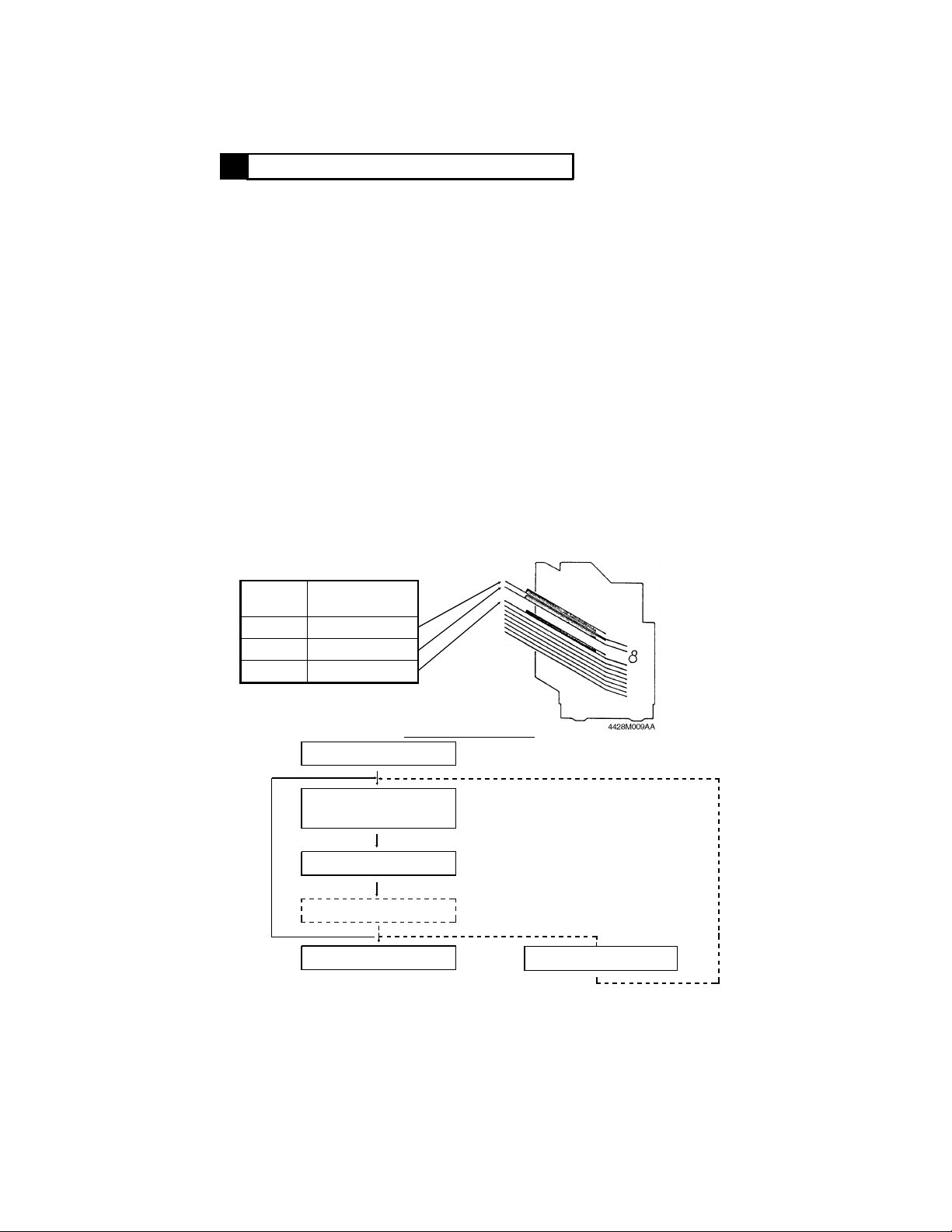
6-2. NON-SORT MODE
When in the Non-Sort Mode, the ST-724/ST-723 feeds all copies out onto
the 1st Bin. It feeds copies into the subsequent Bin as soon as the capacity
of the current Bin is exceeded. (As soon as 25 copies have been fed into the
10th Bin, the Remove Copies Indicator on the copier control panel lights up
and the copier inhibits the initiation of a new copy cycle.)
Example: Making 80 copies
No. of Copies
Bin
Fed In
1st 50
2nd 25
3rd 5
Outline of Operation
Out of Copier
Through
ST-724/ST-723
Fed into 1st Bin
Aligning
End of Operation
…ST-724 only
M-6
When the capacity of the
current Bin is exceeded
Bin Moving
Page 17
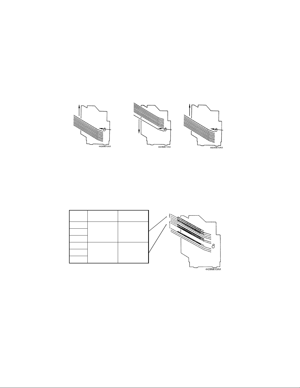
6-3. SORT MODE
● When in the Sort Mode, the ST-724/ST-723 sorts copies into complete
sets of originals, each set being fed out onto a Bin. Sorting is
bi-directional: the copies of the odd-numbered originals are sorted in the
sequence from the 1st Bin to 10th Bin (the Bins moving upward). Copies
of the even-numbered originals are sorted in the sequence from the 10th
Bin to 1st Bin (the Bins moving downward).
Example: Making 10 Copies Each from 3 Different Originals
Direction of Bin Moving for
Copies of 1st Original
Copy
Direction of Bin
Moving for
Copies of 2nd
Original
● When 25 copies have been fed out into the last Bin, the Remove Copies
Direction of Bin Moving for
Copies of 3rd Original
Indicator lights up on the copier control panel and the copier inhibits the
initiation of a new copy cycle. If, however, the 6th and subsequent Bins
are not used in the Sort Mode (i.e., the number of copies to be made has
been set to 5 or less), the Remove Copies Indicator does not light up.
Instead, the ST-724/ST-723 is automatically switched to the Auto Dual
Mode and copying continues using the 6th and subsequent Bins until the
Remove Copies Indicator lights up or the copy cycle is completed.
Example: Making 3 Copies Each from 30 Different Originals
Bin Original
1st
2nd
3rd
6th
7th
8th
1st to 25th 25
26th to 30th 5
No. of Copies
Fed Out
M-7
Page 18

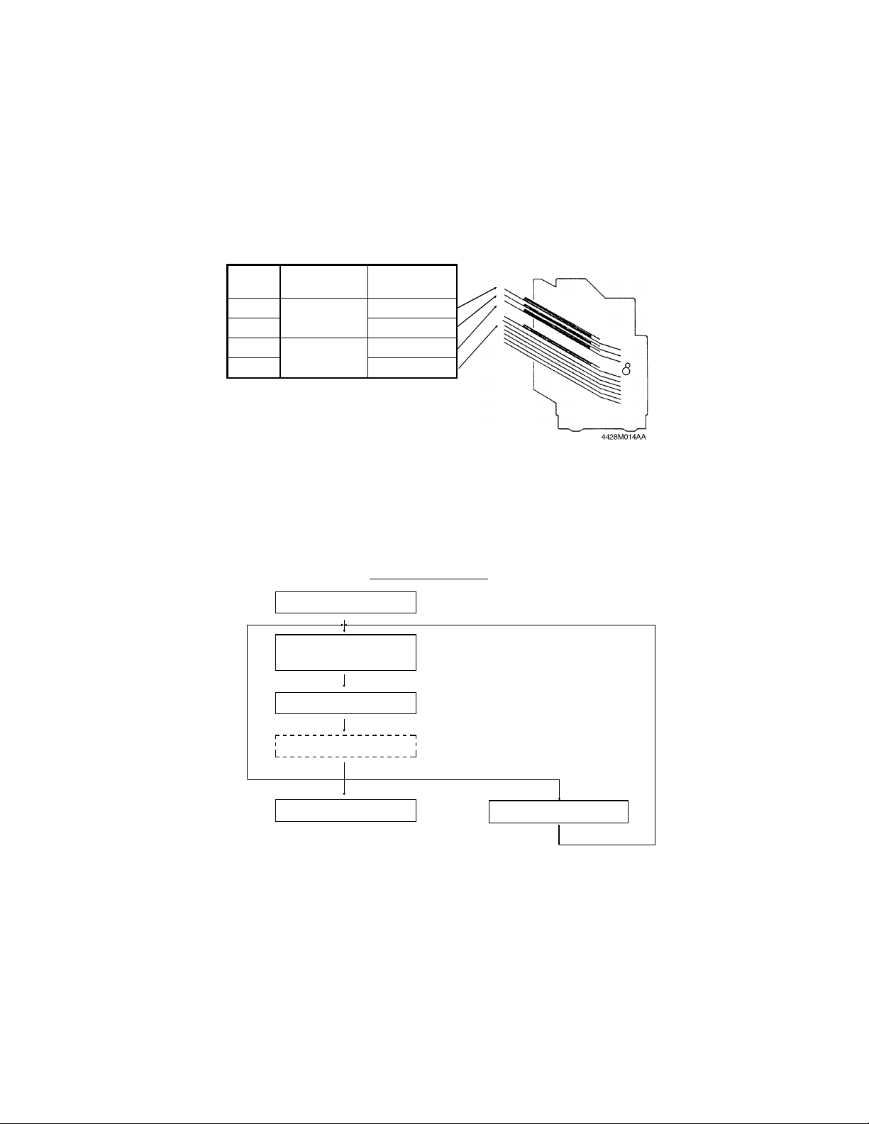
● When the Start Key is pressed with 11 or more set for the number of
Repeats for the no. of
copies set to be made.
copies to be made, the number on the Multi-Copy Display is automatically
changed to 10 and the ST-724/ST-723 operates in the Sort Mode.
Outline of Operation
Out of Copier
Through
ST-724/ST-723
Fed into Bin
Aligning
Bin Moving
…ST-724 only
After the last copy
has been aligned
End of Operation
M-8
Page 19
6-4. GROUP MODE
Repeats for the no. of
copies set to be made.
● When in the Group Mode, the ST-724/ST-723 separates copies made
from a single original into groups, each group containing the same, or a
different, number of copies.
Example: Making 25 Copies Each from 3 Different Originals
Bin Original
1st
2nd 5
3rd
4th 5
● If the settings on the copier control panel and other conditions require
1st
2nd
No. of Copies
Fed Out
25
25
more than 10 Bins, during execution of the copy job, the copier stops the
initiation of a new copy cycle and the Remove Copies Indicator lights up.
If space remains available in the 10th Bin, the Start Key can be pressed
again. All copies of the subsequent original or originals are now fed into
the 10th Bin. However, as soon as the capacity of the 10th Bin is
exceeded, the copier inhibits the initiation of the new copy cycle.
Outline of Operation
Out of Copier
Through
ST-724/ST-723
Fed into Bin
Aligning
End of Operation
…ST-724 only
At the end of the copy
cycle for one original
Bin Moving
M-9
Page 20
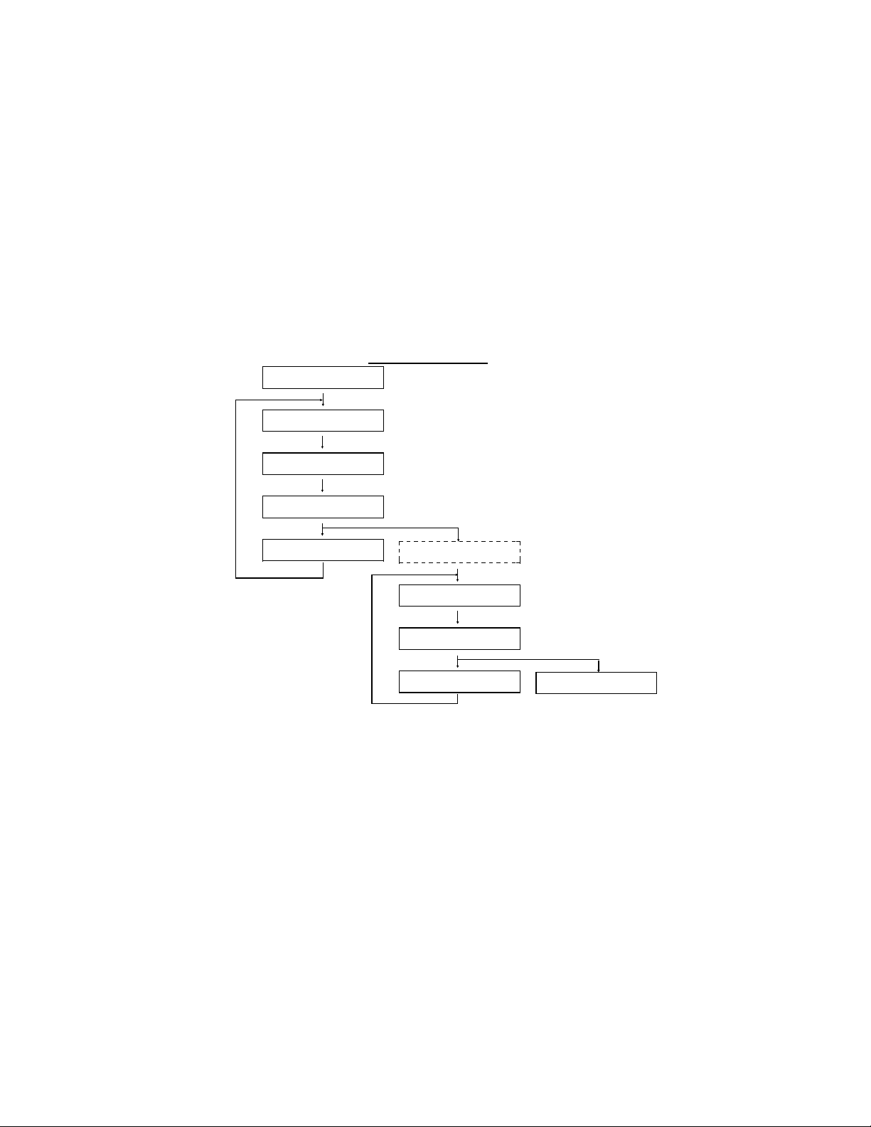
6-5. SORT STAPLE MODE (ST-724 ONLY)
Repeats for the no. of
copies set to be made.
● When in the Sort Staple Mode, the ST-724 automatically staples each of
the copy sets sorted into each Bin (the sorting operation is the same as in
the Sort Mode).
● Stapling action occurs starting with the lowest Bin in use. (For instance, if
1st to 4th Bins are in use, the copy sets are stapled starting with the 4th
Bin.)
● If copies are to be sorted only into the 1st Bin (i.e., when making one copy
each of two different originals), after both copies have been fed into the
1st Bin, the ST-724 moves the Bins to the 2nd Bin position and then back
to the 1st Bin position before initiating the stapling action.
● If the ST-724 is switched to the Auto Dual Mode during sorting, it cancels
the stapling action and sets the ST-724 into the Sort Mode.
Outline of Operation
Out of Copier
Through ST-724
Fed into Bin
Aligning
Bin Moving
● Stapling action is inhibited under any of the following conditions even if
the copy cycle has been initiated in the Sort Staple Mode:
After the last copy
has been aligned
Bin Moving
Clamping
Stapling
Bin Moving
…If the lowest Bin in
…use is not located to
…receive copies
End of Operation
➀ There is a copy or copies present in any of the Bins when the Power
Switch is turned ON and the copy cycle is initiated without having
removed it.
➁ The copy cycle is initiated with copies made in a preceding Non-Sort
cycle still in the Bins.
➂ The copy cycle is initiated with paper inserted into the Bin externally.
➃ There is only one copy in the Bin after sorting.
➄ Copies with different crosswise lengths are in the Bins.
➅ The copy set is not properly conveyed to the stapling position because of
a clamping or other failure (in which case, the ST-724 goes on to staple
the copy set in the next Bin).
M-10
Page 21

6-6. MANUAL STAPLE MODE (ST-724 ONLY)
The following two different operations are possible in the Manual Staple
Mode.
• When the Manual Staple Key on the copier control panel is pressed after
copies have been made in the Sort or Group Mode, the ST-724 staples
together two or more copies in a Bin. (The stapling action and stapling
inhibiting conditions are the same as those in the Sort Staple Mode.)
• When there are no copies in any of the Bins, the ST-724 can staple
together sheets of paper inserted into the 1st Bin by hand when the Manual
Staple Key on the copier control panel is pressed. At this time, the ST-724
performs no aligning action.
Operation
Press the Manual Staple Key.
Clamping
Stapling
End of Operation
No stapling action occurs if the sheets of paper have not properly been
conveyed to the stapling position because of a clamping or other failure.
6-7. BIN MOVEMENT AT END OF COPY CYCLE
If the 1st Bin is not located to receive copies at the end of a copy cycle, the
Bins are moved so that the 1st Bin will be located to receive copies 2 sec.
after copies have been removed from the Bins. This sets the ST-724/ST-723
M-11
Page 22
OPERATION OF EACH MECHANISM
7
7-1. PAPER TRANSPORT MECHANISM
● Paper Path
The paper fed out of the Copier by the Exit Roller in the copier is fed
directly onto the Transport Roller in the ST-724/ST-723. The Transport
Roller turns to feed the paper almost straight into the Bin. During this
time, Sorter Exit Sensor PC2 is unblocked ( ) as the leading edge of
the paper moves past it and blocked ( ) as the trailing edge of the
H
L
paper moves past it. The paper path is constant, as shown below,
regardless of the operating mode selected for use.
Light Blocking Plate
Paper
PC2
Copier
Transport Roller
PC2
● Transport Roller Drive
Exit Roller in Copier
The Transport Roller is driven by the Drive Coupling Gear Assy which
receives drive from the Exit Roller Drive Gear inside the copier (or Duplex
Unit). This means that the Transport Roller turns in phase with the paper
take-up drive of the copier.
= Viewed from Rear of System =
Transport
Roller Pulley
Drive Coupling
Gear Assy
Timing Belt
Copier
or
Duplex
Unit
Exit Roller
Drive Gear
ST-724/ST-723
Drive Coupling
Gear Assy
Transport
Roller Pulley
M-12
Page 23
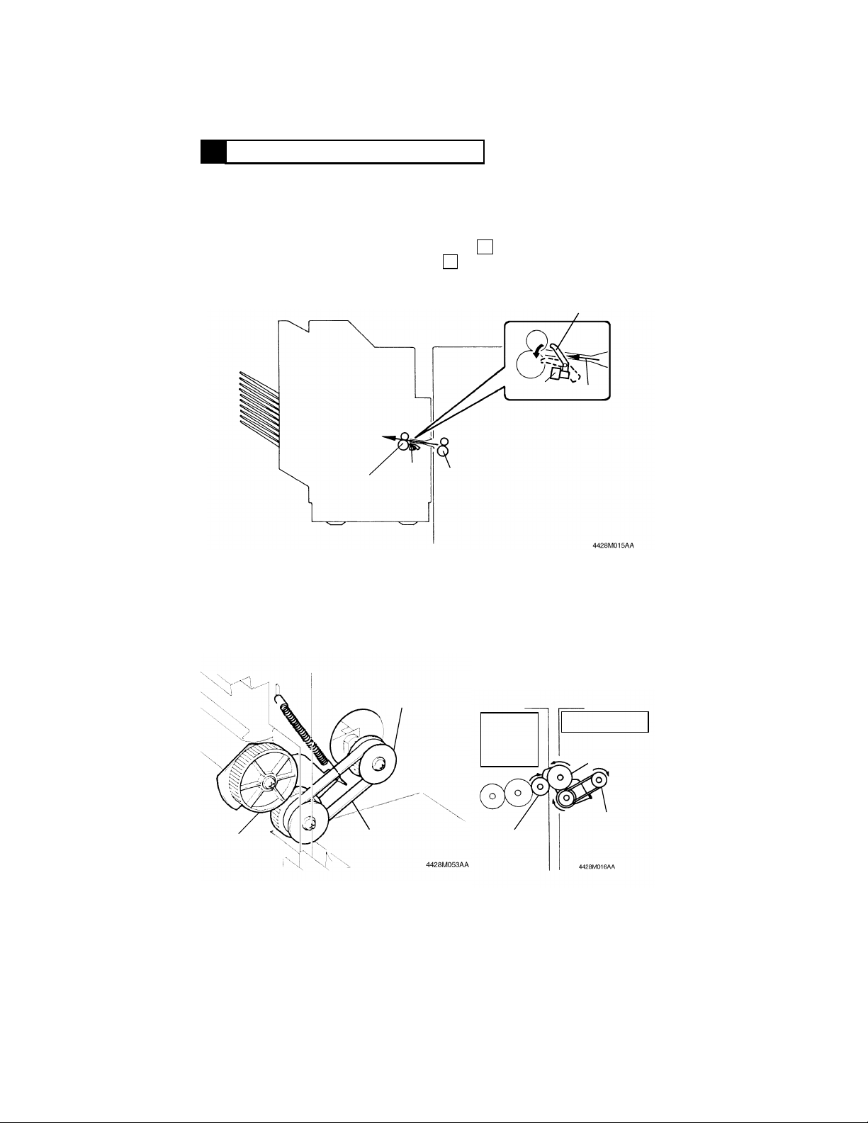
7-2. PAPER ALIGNING MECHANISM (ST-724 ONLY)
● The Paper Aligning Mechanism presses the copies fed into the Bins up
against the Aligning Reference Plate so that they can be aligned in the
crosswise direction. This mechanism will operate only with B5
Lengthwise, 8"
● The copies are aligned by the Paper Aligning Bar which is moved by
× 10" Lengthwise or greater size.
Paper Aligning Motor M3 turning forward or backward. The movement of
the Paper Aligning Bar differs depending on the paper size.
Paper Aligning Home
Position Sensor PC5
Spiral Shaft
M3
M3 Turning
Forward
Paper Aligning
Bar
● Paper Aligning Motor M3
M3 Turning
Backward
Aligning
Reference
Plate
Paper Aligning Motor M3 is a two-phase stepping motor. The output
pulses from pins 12 to 15 of IC1A are applied via IC6A and IC9A to M3 to
control the direction and distance of movement of the Paper Aligning Bar.
Each output pulse from IC1A turns M3 one angular increment, or a step,
which is 7.5°. This is equivalent in the movement of the Paper Aligning
Bar to approx. 0.3 mm. The number of output pulses from IC1A therefore
controls the distance of movement of the Paper Aligning Bar. The output
sequence of pulse signals (steps 1, 2, 3, and 4 or steps 4, 3, 2, and 1), on
the other hand, determines the direction of rotation of M3.
IC1A (Pin No.)
1 2 3 4
12 L L H H
13 H H L L
14 H L L H
15 L H H L
Step
Output Sequence M3 Turning Forward
M3 Turning Backward
M-13
Page 24
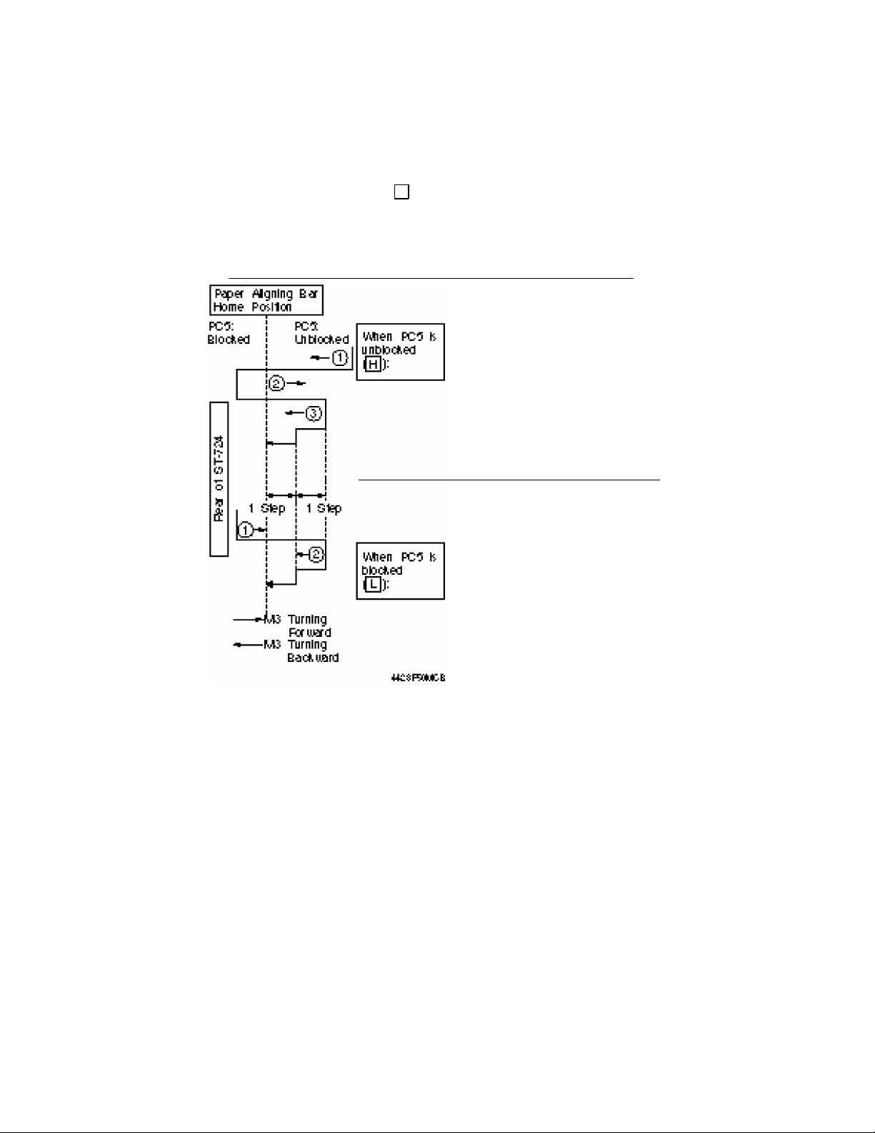
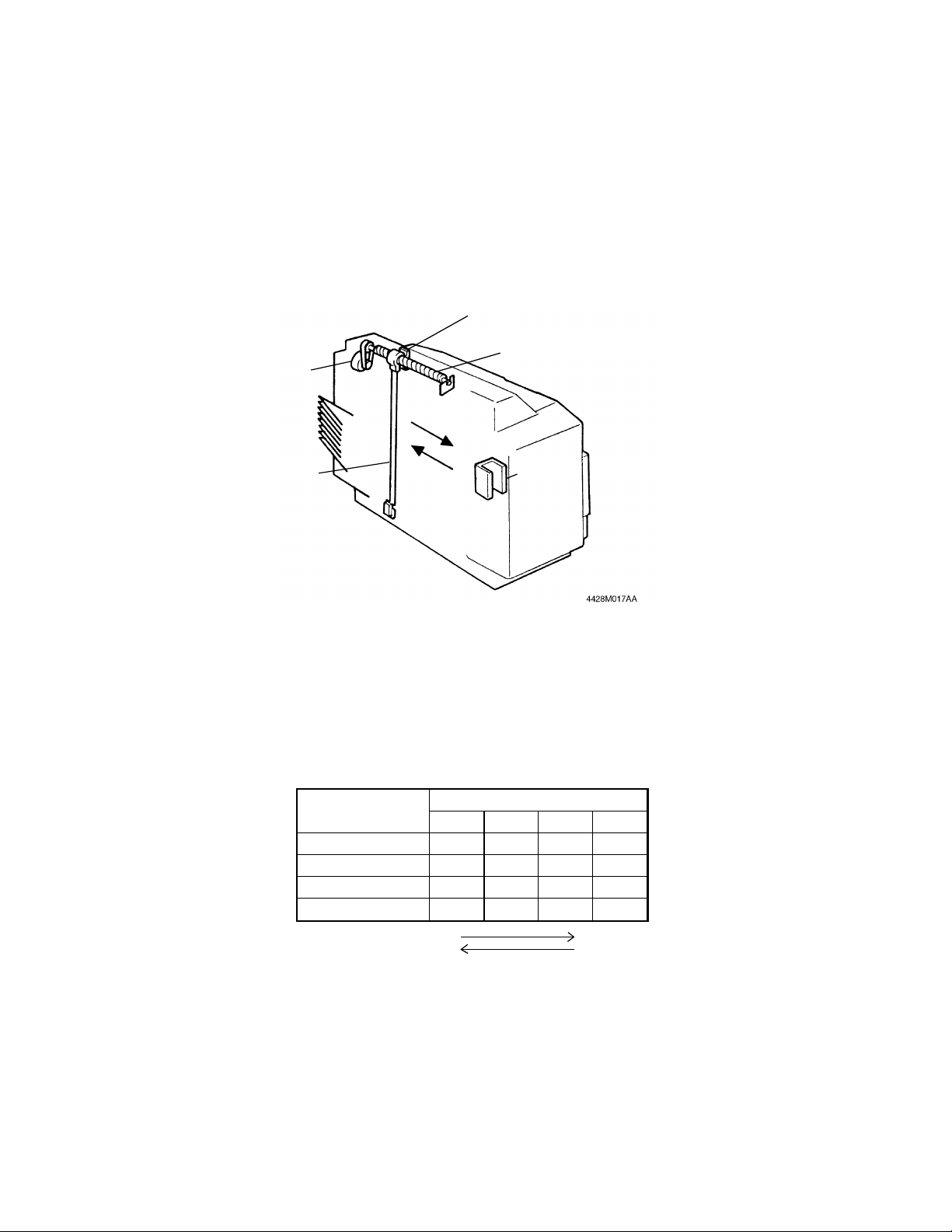
● Paper Aligning Bar Home Position Detection
The home position of the Paper Aligning Bar is where the Light Blocking
Plate fitted to the Paper Aligning Bar has just blocked Paper Aligning
Home Position Sensor PC5 ( ). This position serves as the reference
point, based on which the number of output pulses from IC1A is
calculated for different paper sizes.
Operation When Paper Aligning Bar is Detected at its Home Position
L
➀ M3 is turned backward until
PC5 is blocked.
➁ M3 is turned forward until
PC5 is unblocked.
➂ M3 is turned backward by one
pulse until PC5 is blocked, at
which time M3 is
deenergized. (See NOTE
below.)
➀ M3 is turned forward until
PC5 is unblocked.
➁ M3 is turned backward by one
pulse until PC5 is blocked, at
which time M3 is
deenergized. (See NOTE
below.)
NOTE: CPU checks whether PC5 is blocked or unblocked each time M3 is
The home position of the Paper Aligning Bar is detected under any of the
following timings:
energized for one pulse.
• When Sorter Set Switch S3 is turned ON.
• At the end of each mode (when the last copy has been aligned).
M-14
Page 25
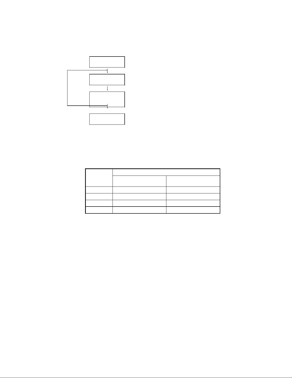
● Outline of Paper Aligning Bar Operation
Home Position
…… The Bar is located near, but not in contact
with, the copy. (See NOTE below.)
…… The Bar presses the copy up against the
Aligning Reference Plate. (See NOTE
below.)
NOTE: Varies for different paper sizes.
➀
Standby Position
Aligning Position
➁
Home Position
➀ During a multi-copy cycle, the Paper Aligning Bar repeatedly
moves between the standby and aligning position until it
completes aligning the last copy.
➁ The Paper Aligning Bar returns to the home position when it
has completed aligning the last copy.
● Number of Pulses (Paper Aligning Bar Movement) for Different Paper
Sizes
Predetermined No. of Pulses
Paper Size
A3 0 51
× 17" 11 62
11"
8-1/2"
A4L 139 190
From Home to
Standby Position
× 11"L 137 188
From Standby to
Aligning Position
L: Lengthwise
M-15
Page 26

● Aligning Operation
Paper Aligning Bar at home position
60 msec. after Sorter Exit Sensor PC2 has
been unblocked ( ) as the leading edge
of the copy fed out of the copier reaches it
H
Paper Aligning Motor M3 turns forward for the predetermined number of
pulses corresponding to the paper size, thereby moving the Paper Aligning
Bar to the standby position.
270 msec. after PC2 has been blocked
( ) as the trailing edge of the copy
L
moves past it
M3 turns forward for the predetermined number of pulses, which moves the
Paper Aligning Bar to the aligning position to align the copy.
60 msec. later
In a multi-copy cycle
M3 turns backward for the
predetermined number of pulses
to return the Paper Aligning Bar to
In a single-copy cycle or at the end
of aligning the last copy
M3 turns backward and the Paper
Aligning Bar is detected at its home
position.
the standby position.
M-16
Page 27
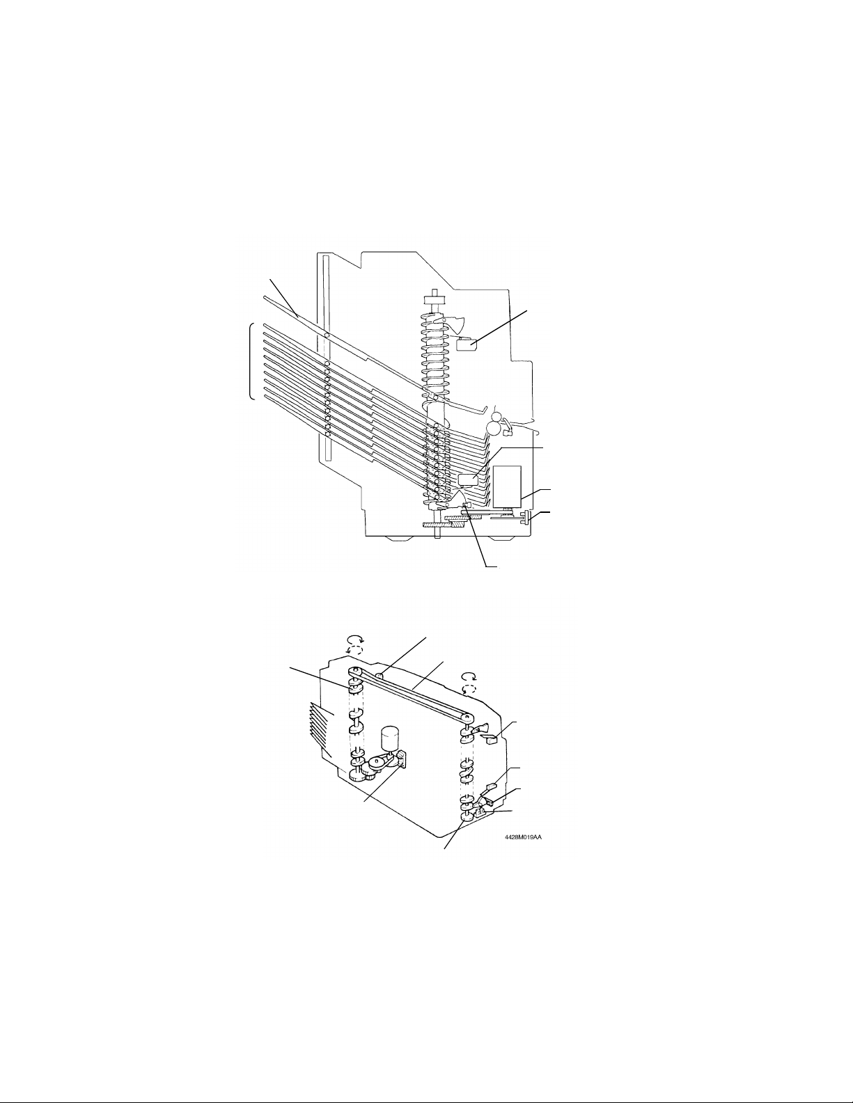
7-3. BIN MOVING MECHANISM
● The Top Bin and 1st to 10th Bin are all held in position by the grooves in
the Side Plate and those in the Spiral Cams. When the Spiral Cams are
turned one complete turn by Bin Moving Motor M1, all Bins and Top Bin
are at once moved up or down (depending on the turning direction of the
Spiral Cam) one Bin position along the grooves in the Spiral Cams.
Top Bin
Bin Upper Limit
Interlock Switch S1
1st to
10th Bin
Bin Lower Limit
Interlock Switch
S2
M1
Bin Moving Pulse
Sensor PC1
Bins Moving Up
Bins Moving Down
Spiral Cam
M1
PC1
Light Blocking Plate
M-17
4428M063AA
Bin Lower Limit Position
Sensor PC4
Pressure Roll
Drive Transmitting Belt
S1
S2
PC4
Bin Positioning
Sensor PC3
Page 28
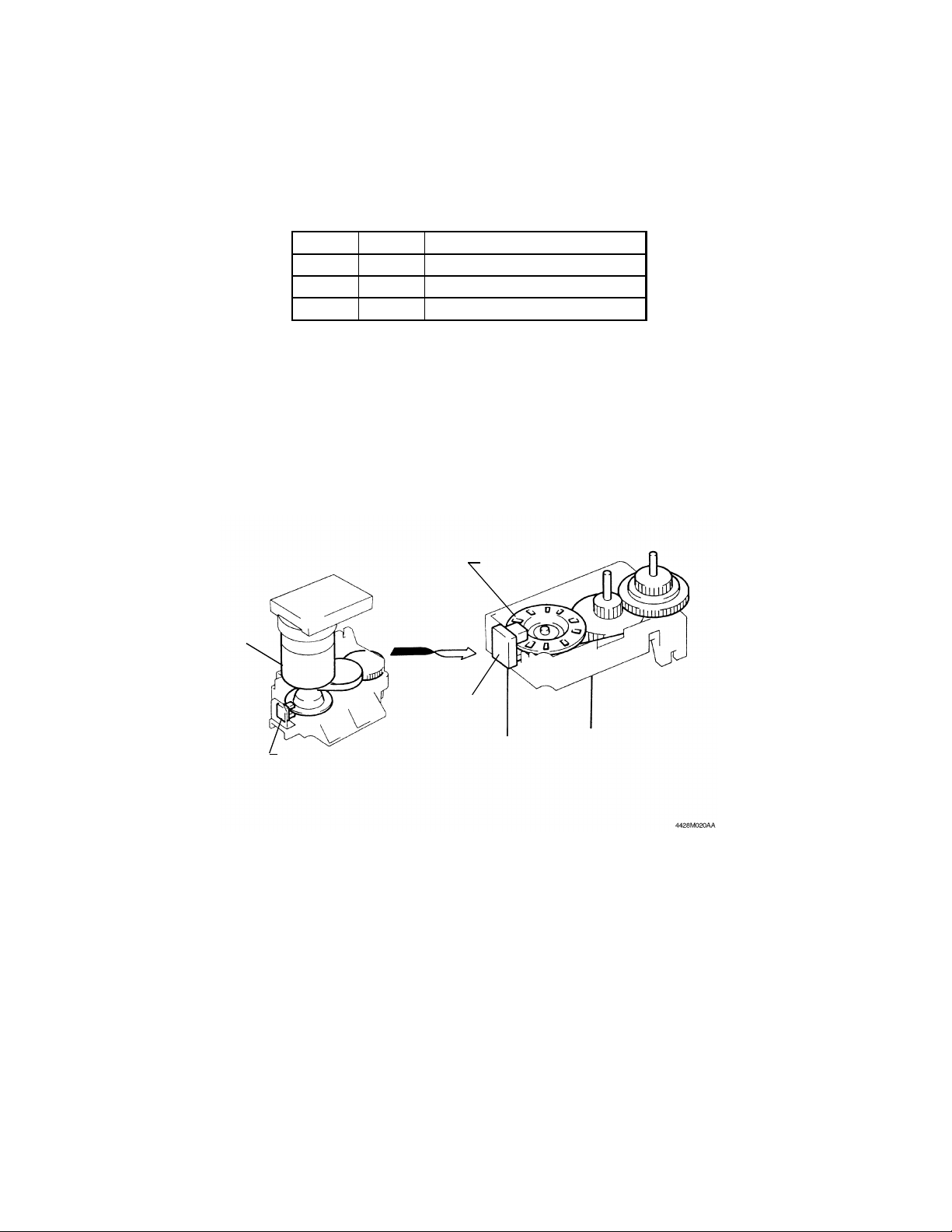
● Bin Moving Motor M1
Bin Moving Motor M1 is a DC motor. The outputs from pins 5 and 6 of
IC1A are applied via IC7A and IC10A to M1. This energizes or
deenergizes M1 and controls the direction of M1 rotation.
IC1A-5 IC1A-6 Direction of M1 Rotation
L H Forward (Bins Moving Up)
H L Backward (Bins Moving Down)
H H Deenergized
If M1 is turned at its maximum speed, Bins vibrate heavily as they move,
resulting in a greater noise. M1 speed is controlled by pulse width
modulation, or PWM, which varies the width of pulses applied to M1,
thereby changing the average voltage applied to M1. The M1 shaft is
fitted with a Pulse Disk and Bin Moving Pulse Sensor PC1 is used to
convert the M1 shaft speed to pulse signals. The CPU knows the shaft
speed by means of the pulse frequency. Based on the output from PC1,
the M1 drive pulses are controlled, thereby minimizing vibration as it
occurs during Bin moving. This contributes to quieter operation.
Pulse Disk
M1
PC1
PC1
M-18
Page 29
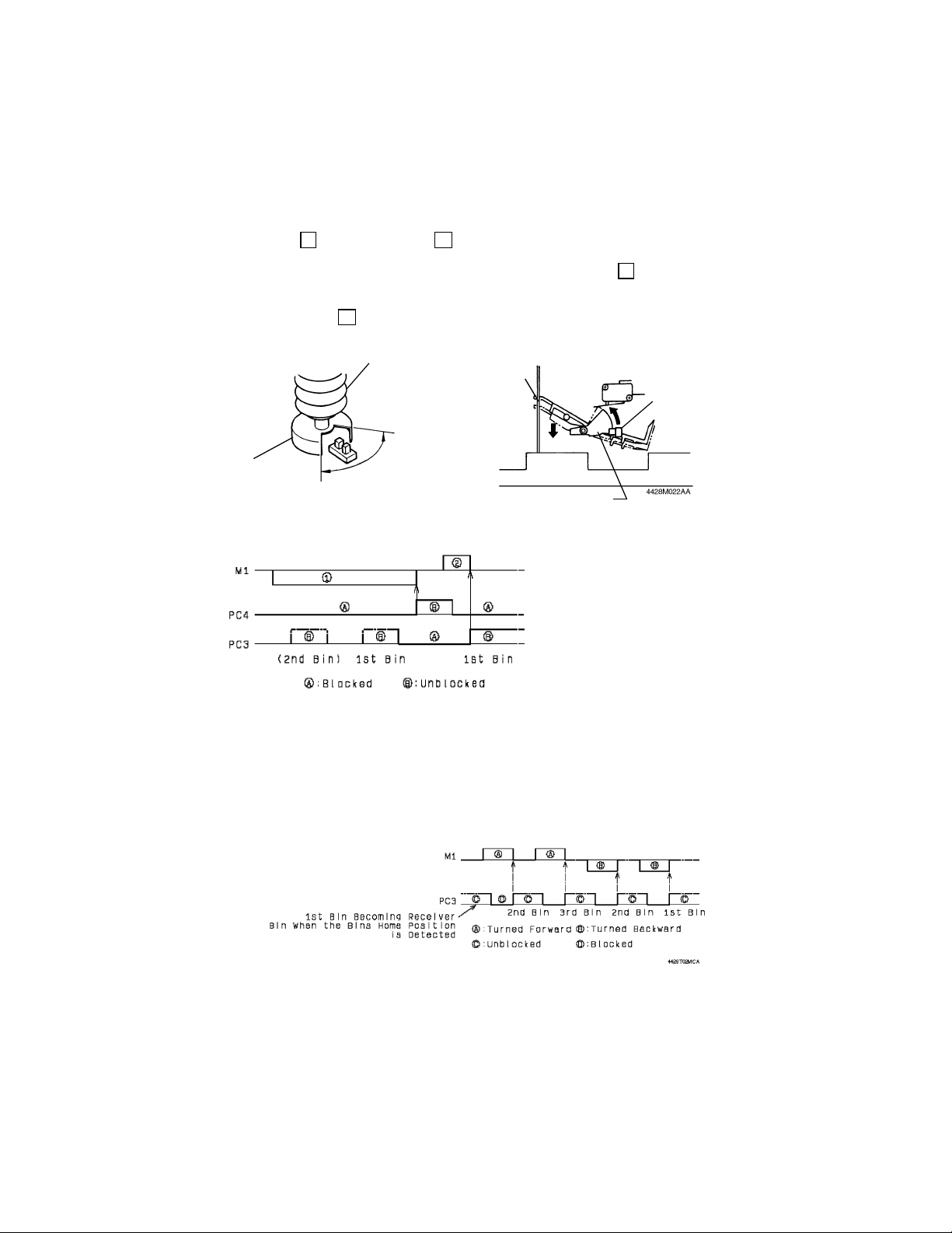
●
Bin Home Position Detection
The home position of the Bins is where the 1st Bin is located to receive
copies fed out of the copier. Movement of each Bin is controlled with this
position as the reference. The Bin home position is detected by Bin
Positioning Sensor PC3 and Bin Lower Limit Position Sensor PC4. PC3 is
blocked ( ) and unblocked ( ) by a Light Blocking Plate which turns
L
H
in phase with the Spiral Cam. It is unblocked when any of the Bins is
located to receive the copy. PC4 is normally kept blocked ( ) by a Light
L
Blocking Plate. However, when the 1st Bin is located lower than the level
to receive the copy, the 10th Bin pushes the Light Blocking Plate, which
unblocks PC4 ( ).
H
Spiral Cam
10th Bin
PC4
Light Blocking
Plate
PC3
Senses that any of
the Bins is located to
receive a copy.
4428M021AA
Light Blocking Plate
Operation at Bin Home Position Detection
➀ M1 is turned backward
until PC4 is unblocked.
➁ M1 is turned forward and
is deenergized as soon
as PC3 is unblocked.
(This is where the 1st Bin
4428T01MCA
The Bin home position is detected under the following timing:
• Sorter Set Switch S3 is turned ON for the first time after the Power
Switch of the copier has been turned ON.
● Bin Moving Control
After the Bin home position is detected, at which time the 1st Bin is
located to receive the copy, movement of the Bins is controlled by the
direction of M1 rotation and the number of times PC3 is blocked and
unblocked.
receives the copy.)
M-19
Page 30
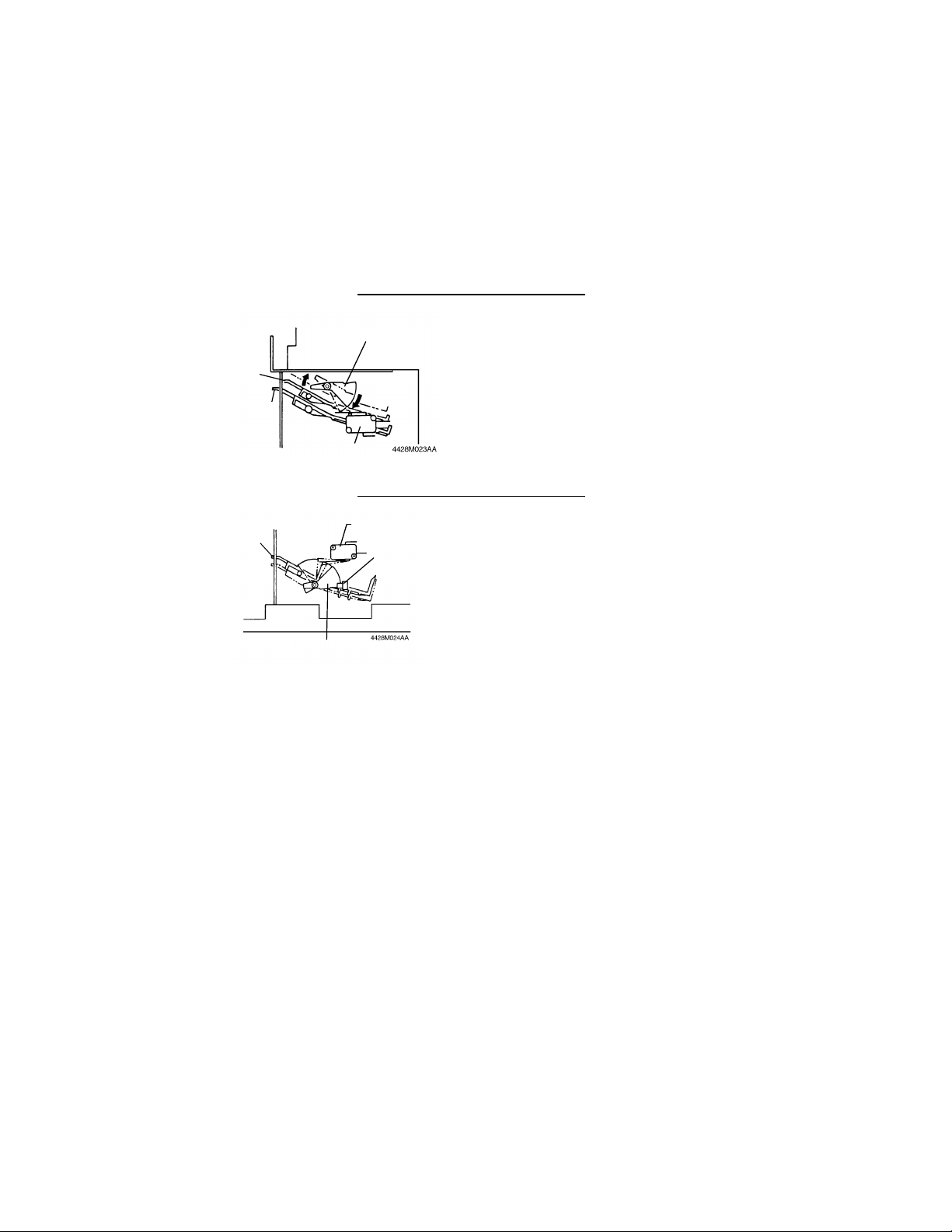
● Bin Upper Limit Interlock Switch S1 and Bin Lower Limit Interlock Switch
S2
For a mechanical or electrical failure, Bin Moving Motor M1 can keep on
turning even when it should remain stationary. Bin Upper Limit Interlock
Switch S1 and Bin Lower Limit Interlock Switch S2 are installed to shut
down the DC24V power supply to M1, thereby bringing it to a stop if such
trouble occurs.
Bin Upper Limit Interlock Switch S1
If, during the upward motion of the Bins,
Actuator
Top Bin
the Bins continue moving upward above
the upper limit position (which is where
the 10th Bin is located to receive the
copy), the Actuator is swung by the Top
1st Bin
S1
Bin Lower Limit Interlock Switch S2
Bin as shown on the left, actuating S1 to
cut off the power supply to M1.
If, during the downward motion of the
Bins, the Bins continue moving
downward, having moved past the level
which unblocks Bin Lower Limit Position
10th Bin
S2
PC4
Sensor PC4, the Light Blocking Plate of
PC4 actuates S2 as shown on the left,
thus shutting down the power supply to
M1.
Light Blocking Plate
● Purpose of Installation of Top Bin
The paper this machine handles is mainly colored copies. Colored copies
tend to develop a slight face curl and, as a result, the copies fed out into
the1st Bin in the Sort mode can be misaligned with each other in the bin.
(With the 2nd Bin and lower, the copies fed into each bin are held by the
immediately upper bin and therefore the curl is minimized in the copies.)
The Top Bin in this machine therefore functions to keep the copies down
as they are fed into the 1st Bin.
M-20
Page 31

7-4. PAPER CLAMPING MECHANISM (ST-724 ONLY)
● The Paper Clamp Unit uses its jaws to clamp the copy set in the Bin and
moves it to the stapling position. After the copy set has been stapled
together, the jaws return it back to the Bin.
Jaws
Paper Clamp
Solenoid SL1
Paper Clamp
Motor M2
Paper Clamp Home
Position Sensor PC6
● The paper clamping operation consists of, (1) the Paper Clamp Unit being
moved between the home position (which is the stapling position) and the
clamping position by Paper Clamp Motor M2, and (2) the Jaws of the
Paper Clamp Unit clamping and unclamping the copy set as Paper Clamp
Solenoid SL1 is energized and deenergized.
● Paper Clamp Motor M2
A DC motor is used as Paper Clamp Motor M2. The output from pin 17 of
IC1A energizes or deenergizes M2 which turns in one direction only.
IC1A-17 M2
L Energized
H Deenergized
M-21
Page 32

● Moving Mechanism and Position Detection of Paper Clamp Unit
The Paper Clamp Unit is supported by four Rolls which run along the
Rails fitted to the Front Frame. Installed under the Paper Clamp Unit is a
Cam Slider, in which a Cam coupled to the drive shaft of M2 is fitted.
When M2 is energized to turn the Cam one turn, the Paper Clamp Unit
moves from home to the clamping position and then back to home
position.
Cam Slider
Cam
PC6
Cam Slider
Cam
Light Blocking
Plate
M2
Rail
Rolls
Rail
4428M026AA
Paper Clamp Home Position Sensor PC6 detects the Paper Clamp Unit at its
home (stapling) position and clamping position. PC6 is blocked ( ) and
unblocked ( ) by a semicircular Light Blocking Plate that turns in phase
H
L
with the Cam. The home position and clamping position are detected by the
Blocking Edge and Unblocking Edge of the Plate.
The Blocking Edge is where PC6 is just blocked, which is the home
position.
The Unblocking Edge is where PC6 is just unblocked, which is the
clamping position.
Paper Clamp Unit
Moving from Clamping
to Home Position
Home Position
Paper Clamp Unit
Moving from Home
to Clamping Position
Clamping Position
PC6
4428M028AA
Blocking Edge
4428M029AA
Being Blocked
4428M030AA
Unblocking Edge
Being Unblocked
4428M031AA
M2 is energized under the following timing to detect the home position of the
Paper Clamp Unit:
• Sorter Set Switch S3 is turned ON for the first time after the Power Switch
of the copier has been turned ON.
M-22
Page 33

● Paper Clamping Mechanism
As Paper Clamp Motor M2 turns, the Paper Clamp Unit moves to the
paper clamping position. Paper Clamp Solenoid SL1 is then energized.
When SL1 is energized, it moves the Lower Jaw upward by way of the
Lower Arm. At the same time, the Upper Arm which is in gear with the
Lower Arm pushes the Upper Jaw down. This results in the Upper and
Lower Jaws clamping the copy set. In addition, Pin A of the Lower Jaw
hooks catch B of the Aligning Reference Plate. This is done to move the
Aligning Reference Plate, together with the copy set, to the stapling
position.
SL1 is deenergized when the Paper Clamp Unit moves back again to the
clamping position after stapling. When SL1 is deenergized, the Jaws are
returned back to the original position via the Upper and Lower Arms by
the torsion spring fitted to the Lower Arm. (The Aligning Reference Plate
is returned to the original position by torsion springs C and D fitted to it,
as the Paper Clamp Unit moves to the paper clamping position.)
Home Position (Before Operation)
C
Upper Jaw
Aligning
Reference
Plate
Lower Jaw
D
Upper Arm
Gear
Coupling
Lower Arm
Torsion
Spring
SL1
At Clamping
A
B
M-23
Page 34

● Paper Clamping Operation
Paper Clamp Unit at home position
Paper Clamp Motor M2 is energized to move the Paper Clamp Unit
toward the clamping position.
M2 is deenergized as the Unblocking Edge of the Light Blocking Plate
reaches Paper Clamp Home Position Sensor PC6.
70 msec. later
Paper Clamp Solenoid SL1 is energized and the Jaws clamp the copy set.
70 msec. later
M2 is energized to move the Paper Clamp Unit toward the stapling
position.
M2 is deenergized as the Blocking Edge of the Light Blocking Plate
reaches PC6.
70 msec. later
(The copy set is stapled together. ... See 7-6. STAPLING MECHANISM.)
75 msec. later
M2 is energized to move the Paper Clamp Unit toward the clamping
position.
M2 is deenergized as the Unblocking Edge of the Light Blocking Plate
reaches PC6.
70 msec. later
SL1 is deenergized and the Jaws open to unclamp the stapled copy set.
70 msec. later
M2 remains energized until the Blocking Edge of the Light Blocking Plate
reaches PC6, allowing the Paper Clamp Unit to return to the home
position.
M-24
Page 35

7-5. PAPER DETECTION AT STAPLING MECHANISM (ST-724 ONLY)
In the beginning of a stapling sequence, the copy set in the Bin is moved to
the stapling position by the Paper Clamp Unit. Paper Clamping Sensor PC8
is used to check to see whether the copy set has been properly moved to
the stapling position before each stapling action occurs. If PC8 is not
blocked (
H ) by the copy set even when the Paper Clamp Unit has moved
to the stapling position because of a clamp failure or other reason, the
stapling action for that particular Bin is canceled and the sequence is started
for the stapling action for the next Bin.
PC8
Copy Set
7-6. STAPLING MECHANISM (ST-724 ONLY)
● The Staple Unit has a Stapler Arm that is moved up and down by Stapling
Motor M4 to drive a staple into the copy set.
Stapler Home Position
Detecting Switch S4
Plunger Guide
Staple Forming
Mechanism
Stapling Table
M4
Knob
Stapler Arm
Paper Clamping Sensor
PC8
Staple Cartridge
Reverse Feed Check
4428M034AA
M-25
Page 36

● Stapling Motor M4
Stapling Motor M4, a DC motor, is energized or deenergized by the output
from pin 20 of IC1A. It turns in one direction only.
IC1A-20 M4
L Energized
H Deenergized
Stapler Arm Moving Mechanism
●
A cam slot is cut into the Stapler Arm, which the Roll on Gear D fits in.
When Stapling Motor M4 is energized to turn Gear D one complete turn
through a gear train of Gears A, B, and C, the Roll on Gear D causes the
Stapler Arm to move through the upper and lower limit positions once.
Upper Limit Position (Home Position)
Stapler Arm
M4
Roll
Cam slot
In Upward Stroke
Gear A
Gear B
Gear C
Gear D
In Downward Stroke
Lower Limit Position
M-26
Page 37

● Stapler Arm Home Position Detection
The home position of the Stapler Arm is detected by Stapler Home
Position Detecting Switch S4 which is actuated and deactuated by part A
of the Plunger Guide fitted to the Stapler Arm. The output from S4 is
applied to pin 1 of IC1A.
S4 IC1A-1
At Home Position ON L
When Arm Moves OFF H
At Home Position
Stapler Arm
S4
S4
A
Plunger Guide
Plunger
Guide
S4: ON
When Arm Moves
S4
Pushbutton
S4 Pushbutton
S4: OFF
A check is made to make sure if the Stapler Arm is at the home position
under the following timing. If the Stapler Arm is not detected at its home
position (S4 is deactuated), Stapling Motor M4 is energized and, when S4 is
actuated, is deenergized. (This is the sequence of operation to detect the
home position of the Stapler Arm.)
• Sorter Set Switch S3 is turned ON for the first time after the Power Switch
of the copier has been turned ON.
M-27
Page 38

● Staple Forming Mechanism
The staple forming mechanism consists of the Guide Plate, Former,
Driver, and Face Plate.
Guide Plate
(Front Sheath)
Former
Bending
Block
• The Guide Plate functions as a guide to hold the Former and Driver. The
A
Staple Sheet
Plunger Guide
Body
Driver
Face Plate
4428M037AA
Bending Block of the Guide Plate serves as a stopper for the staple sheet
being fed. The groove at A in the Bending Block holds the first, or front
staple of the staple sheet.
• The Former forms the front staple of the staple sheet held by the Bending
Block into an inverted-U shape.
• The Driver, fixed onto the Plunger Guide, separates the formed staple from
the staple sheet and drives it into the copy set.
• The Face Plate is fixed to the Body and presses the copy set down when
the staple is driven into it.
M-28
Page 39

● Operation of the Staple Forming Mechanism
1. As Stapling Motor M4 turns,
Body
Copy
Set
2. The Body reaches the copy set
the Stapler Arm moves
downward. At this time the
Body is pushed downward by
the Plunger Guide.
and stops moving. At this time,
the Face Plate presses the
copy set downward.
Driver
A
Former
Guide
Plate
Copy
Set
B
Bending
Block
Plunger Guide
Bending Block
Driver
A
Staple Sheet
Former
Former
4428M039AA
Driver
4428M040AA
Driver
Former
Stapling
Table
4428M041AA
3. As the Stapler Arm (i.e.
Plunger Guide) moves further
downward, the Former is
pushed by Claws A of the
Driver and moves downward to
form into an inverted-U the
first staple of the staple sheet
held in position by the Bending
Block.
4. Claws A of the Driver slide
along protrusions B of the
Guide Plate, slipping behind
the Former. The tip of the
Driver then reaches the first
staple of the staple sheet.
(At this time, the Bending
Block is pushed in the
direction of the arrow by the tip
of the Driver, releasing the first
staple.)
5. The Former reaches the copy
set and stops moving. The
Driver, on the other hand,
moves further downward to
separate the formed staple
from the staple sheet and
drives it into the copy set.
(The staple driven into the
copy set is bent by the
Stapling Table. This completes
the stapling action.)
M-29
Page 40

Former Moves
Upward As Driver
Does So.
Former
C
Driver
Plunger
Guide
6. The Stapler Arm (i.e. Plunger
Guide) moves upward from the
lower limit position. At this
time, the Driver moves upward.
7. Since the protrusion of the
Former fits into slot C in the
Driver, the Former is moved
upward as the Driver moves
upward.
Plunger Guide
Body Moves Upward As
Driver and Former Do So.
Face Plate
S4
8. Since the protrusion of the
Former fits into rectangular
hole D in the Face Plate, the
Body also moves upward.
D
Body
9. The Plunger Guide actuates
Stapler Home Position
Detecting Switch S4, which
deenergizes M4. This
completes the stapling action.
M-30
Page 41

● Moving Stapler Arm Pivot Axis
More Sheets of Paper
Less Sheets of Paper
The lower limit position of the Stapler Arm varies depending on the
number of sheets of paper to be stapled together. Since the Roll on Gear
D fits into the cam slot in the Stapler Arm, however, the Stapler Arm at its
cam slot end can move along only a given trajectory.
The pivot axis of the Arm is therefore made movable, thereby
compensating for the varying lower limit positions of the Arm depending
on the number of sheets of paper to be stapled together.
Pivot Axis
More Sheets of
Paper
Less
Sheets of
Paper
Stapler Arm
M-31
Page 42

● Staple Feed Mechanism
The staple sheet is fed one staple at a time onto the Bending Block by the
Feed Spring fitted to the Feeder.
Staple Feeding
When a Staple Cartridge is placed in position, tension is applied to the
Feeder in the direction of the arrow by the Cartridge, meaning that the
Feeder is pressed against the Driver.
Driver
Bending Block
Feeder
Cartridge
Staple Sheet
Feed Spring
When the Driver and Former move down as the Stapler Arm moves down,
the protrusion of the Former pushes the Feeder back in the direction of
the arrow, moving the Feed Spring one staple backward. (Because of the
Reverse Feed Check of the Staple Cartridge, the staple sheet is not
moved backward by the Feed Spring at this time.)
Former
Reverse Feed Check
When the Stapler Arm moves up after a staple has been driven into the
copy set, the Driver and Former move up. As a result, the Feeder is no
longer pushed by the protrusion of the Former and, instead, it is again
pushed toward the Driver. Since the Feed Spring moves in the direction of
the arrow at this time, the staple sheet is fed one staple to the Bending
Block.
M-32
Page 43

● Staple Sheet Empty Detection
Staple Empty Detecting Sensor PC10 is used to detect whether there is a
staple sheet or not in the Staple Cartridge. PC10 is a reflector-type
photosensor. When there is a staple sheet, the light from PC10 LED is
reflected by the staple sheet, turning ON the PC10 phototransistor. This
results in a LOW signal being input to pin 62 of IC1A. If there is no staple
sheet, the LED light is not reflected, which turns OFF the phototransistor.
At this time, a HIGH signal is input to pin 62 of IC1A and the Add Staple
Indicator lights up on the copier control panel.
Staple Sheet IC1A-62
Present L
Not Present H
Staple Sheet
Body
PC10
• A staple-sheet-empty condition is detected when there are about 60
staples remaining in the Staple Cartridge.
• If a staple-sheet-empty condition is detected during a stapling action, that
particular stapling sequence is continued until it is completed. After the
sequence has been completed, the Add Staple Indicator lights up.
• Immediately after a new Staple Cartridge has been installed, the Stapler is
operated to complete four consecutive stapling sequences (it is stopped
when Stapler Home Position Detecting Switch S4 is actuated a fourth
time). This is done to prevent a "dummy run" (an operation of the Stapler
without actually driving a staple into the paper) immediately following the
replacement of the Cartridge.
M-33
Page 44

● Stapling Operation Sequence
The Paper Clamp Unit moves the copy set in the Bin to the stapling
position.
Paper Clamping Sensor PC8 is blocked (
the stapling position.
A LOW signal is output from pin 20 of IC1A to energize Stapling Motor M4.
The Stapler Arm moves down and then up. (This completes the stapling of
the copy set.)
Stapler Home Position Detecting Switch S4 is actuated.
A HIGH signal is output from pin 20 of IC1A to deenergize M4.
The Paper Clamp Unit returns the stapled copy set back into the Bin.
L ) by the copy set moved into
M-34
Page 45

7-7. SORTER SET SWITCH
● Sorter Set Switch S3 is used to detect whether or not the ST-724/ST-723
is locked to the copier. When the ST-724/ST-723 is locked to the copier,
the protrusion of the mounting bracket actuates S3. The output from S3 is
detected by pin 2 of IC1A.
● When S3 is turned ON, the DC24V power of the copier is supplied to the
ST-724/ST-723.
S3 IC1A-2
When Connected ON L
S3
Protrusion of
Mounting Bracket
M-35
Page 46

7-8. BIN EMPTY DETECTION
● Bin Empty Sensor LED Board PWB-B and Bin Empty Sensor PQ Board
PWB-C work as a pair to detect a sheet of paper present in any of the
Bins. Depending on whether there is a sheet of paper present in the Bin,
PWB-B is blocked or unblocked, changing the output from pin 2 of IC1C
on PWB-C as follows.
● Pulses are output from pin 4 of IC1C on PWB-C and these pulses turn ON
and OFF LD1 on PWB-B repeatedly. IC1C on PWB-C determines if a
sheet of paper is present in the bin based on a light beam that strikes it in
synchronism with these pulses. This prevents erroneous detection of a
paper-empty condition caused by extraneous light.
Paper in Bin IC1C-2
Present H
Not Present L
PWB-B
M-36
PWB-C
Page 47

OPERATION IN EACH MODE
8
8-1. NON-SORT MODE
When the Fusing Motor begins in the copier, the Transport Roller is
turned by the Drive Coupling Gear Assy.
∗
... ST-724 Only.
Sorter Exit Sensor PC2 is unblocked (
copy moves past it.
60 msec. later
Paper Aligning Motor M3 turns forward for the specified number of pulses
(which varies depending on the paper size) to move the Paper Aligning
Bar to the standby position.
PC2 is blocked (
M3 turns forward for the specified
number of pulses, causing the Paper
Aligning Bar to align the copy fed into
the Bin.
M3 turns backward for the specified
number of pulses to move the Paper
Aligning Bar to the standby position.
PC2 is unblocked as the leading edge of the next copy moves past it.
PC2 is blocked as the trailing edge of the last copy moves past it.
M3 turns forward for the specified
number of pulses, causing the Paper
Aligning Bar to align the copy fed into
the Bin.
M3 turns backward, then the Paper
Aligning Bar is detected at its home
position.
L ) as the trailing edge of the copy moves past it.
270 msec. later
60 msec. later
270 msec. later
60 msec. later
H ) as the leading edge of the
When the capacity of
the current Bin is
exceeded: 480 msec.
later
Bin Moving Motor M1 is turned
forward until Bin Positioning
Sensor PC3 (in an unblocked
state,
H ) is blocked ( L ) and
then unblocked to move the Bins
so that the 2nd Bin, instead of the
previous 1st Bin, receives the
copy.
When the Fusing Motor stops
turning in the copier, the
Transport Roller stops turning.
M-37
Page 48

8-2. SORT MODE
Example: Making 2 copies each of 2 different originals in the Sort Mode
When the Fusing Motor begins in the copier, the Transport Roller is turned
by the Drive Coupling Gear Assy.
∗ ... ST-724 Only.
Sorter Exit Sensor PC2 is unblocked (
copy moves past it.
60 msec. later
Paper Aligning Motor M3 turns forward for the specified number of pulses
(which varies depending on the paper size) to move the Paper Aligning Bar
to the standby position.
PC2 is blocked (
M3 turns forward for the specified
number of pulses, causing the Paper
Aligning Bar to align the copy fed into
the Bin.
M3 turns backward for the specified
number of pulses to move the Paper
Aligning Bar to the standby position.
PC2 is unblocked as the leading edge of the second copy moves past it.
PC2 is blocked as the trailing edge of the second copy moves past it.
M3 turns forward for the specified number of pulses, causing the Paper
Aligning Bar to align the copy fed into the Bin.
M3 turns backward for the specified number of pulses to move the Paper
Aligning Bar to the standby position.
L ) as the trailing edge of the first copy moves past it.
270 msec. later
60 msec. later
270 msec. later
60 msec. later
H ) as the leading edge of the first
480 msec. later
Bin Moving Motor M1 is turned
forward until Bin Positioning
Sensor PC3 (in an unblocked
state,
H ) is blocked ( L ) and
then unblocked to move the
Bins so that the 2nd Bin,
instead of the previous 1st Bin,
receives the copy.
PC2 is unblocked as the leading edge of the first copy of the second original
moves past it.
PC2 is blocked as the trailing edge of the first copy of the second original
moves past it.
To ➀ on next page
To
➁ on next page
M-38
Page 49

➀
270 msec. later
M3 turns forward for the specified
number of pulses, causing the Paper
Aligning Bar to align the copy fed into
the Bin.
60 msec. later
M3 turns backward for the specified
number of pulses to move the Paper
Aligning Bar to the standby position.
PC2 is unblocked as the leading edge of the second copy of the second
original moves past it.
PC2 is blocked as the trailing edge of the second copy of the second original
moves past it.
270 msec. later
M3 turns forward for the specified
number of pulses, causing the Paper
Aligning Bar to align the copy fed into
the Bin.
60 msec. later
M3 turns backward, then the Paper
Aligning Bar is detected at its home
position.
M1 is turned backward until
PC3 (in an unblocked state,
H ) is blocked ( L ) and
then unblocked to move the
Bins so that the 1st Bin,
instead of the previous 2nd
Bin, receives the copy.
When the Fusing Motor stops
turning in the copier, the
Transport Roller stops turning.
➁
480 msec. later
M-39
Page 50

8-3. GROUP MODE
Example: Making 2 copies each of 2 different originals in the Group Mode
When the Fusing Motor begins in the copier, the Transport Roller is turned
by the Drive Coupling Gear Assy.
∗ ... ST-724 Only.
Sorter Exit Sensor PC2 is unblocked (
copy moves past it.
60 msec. later
Paper Aligning Motor M3 turns forward for the specified number of pulses
(which varies depending on the paper size) to move the Paper Aligning Bar
to the standby position.
PC2 is blocked (
M3 turns forward for the specified number of pulses, causing the Paper
Aligning Bar to align the copy fed into the Bin.
M3 turns backward for the specified number of pulses to move the Paper
Aligning Bar to the standby position.
PC2 is unblocked as the leading edge of the second copy moves past it.
PC2 is blocked as the trailing edge of the second copy moves past it.
M3 turns forward for the specified
number of pulses, causing the Paper
Aligning Bar to align the copy fed into
the Bin.
M3 turns backward for the specified
number of pulses to move the Paper
Aligning Bar to the standby position.
L ) as the trailing edge of the first copy moves past it.
270 msec. later
60 msec. later
270 msec. later
60 msec. later
H ) as the leading edge of the first
480 msec. later
Bin Moving Motor M1 is turned
forward until Bin Positioning
Sensor PC3 (in an unblocked
state,
H ) is blocked ( L ) and
then unblocked to move the
Bins so that the 2nd Bin,
instead of the previous 1st Bin,
receives the copy.
PC2 is unblocked as the leading edge of the first copy of the second original
moves past it.
PC2 is blocked as the trailing edge of the first copy of the second original
moves past it.
270 msec. later
M3 turns forward for the specified number of pulses, causing the Paper
Aligning Bar to align the copy fed into the Bin.
To
➀ on next page
M-40
Page 51

➀
60 msec. later
M3 turns backward for the specified number of pulses to move the Paper
Aligning Bar to the standby position.
PC2 is unblocked as the leading edge of the second copy of the second
original moves past it.
PC2 is blocked as the trailing edge of the second copy of the second original
moves past it.
M3 turns forward for the specified
270 msec. later
number of pulses, causing the Paper
Aligning Bar to align the copy fed into
the Bin.
60 msec. later
M3 turns backward, then the Paper
Aligning Bar is detected at its home
When the Fusing Motor stops
turning in the copier, the
Transport Roller stops turning.
M-41
Page 52

8-4. SORT STAPLE MODE (ST-724 ONLY)
Example: Making 2 copies each of 2 different originals in the Sort Staple
Mode
All copies have been fed out into the Bins and the Paper Aligning Bar
returns to the home position. (The operation to feed copies into the Bins
is the same as in the Sort Mode.)
480 msec. after Sorter Exit Sensor PC2 has been blocked as the
trailing edge of the last copy moves past it
Bin Moving Motor M1 is turned forward until Bin Positioning Sensor PC3 (in
an unblocked state,
H ) is blocked ( L ) and then unblocked to move the
Bins so that the 2nd Bin, instead of the previous 1st Bin, receives the copy.
85 msec. later
Paper Clamp Motor M2 is energized to move the Paper Clamp Unit toward
the paper clamp position. ............................................................................(A)
M2 is deenergized as the Unblocking Edge of the Light Blocking Plate
reaches Paper Clamp Home Position Sensor PC6.
70 msec. later
Paper Clamp Solenoid SL1 is energized and the Jaws clamp the copy set.
70 msec. later
M2 is energized to move the Paper Clamp Unit which holds the copy set
toward the stapling position.
When the copy set is
successfully clamped
M2 is deenergized as the Blocking Edge
of the Light Blocking Plate reaches PC6.
70 msec. later
Paper Clamping Sensor PC8 is
blocked.
Stapling Motor M4 is energized and the stapling sequence is started (only if
PC8 is blocked).
M4 is deenergized when Stapler Home Position Detecting Switch S4 (in the
ON position) is turned OFF and then turned ON, completing the stapling
sequence.
75 msec. later
M2 is energized to move the Paper Clamp Unit toward the clamping position
(to return the stapled copy set back into the Bin).
M2 is deenergized as the Unblocking Edge of the Light Blocking Plate
reaches PC6.
70 msec. later
SL1 is deenergized and the Jaws open to unclamp the stapled copy set.
To ➀ on next page
M-42
Page 53

➀
70 msec. later
M2 remains energized until the Blocking Edge of the Light Blocking Plate
reaches PC6, allowing the Paper Clamp Unit to return to the home
position. .........................................................................................................(B)
205 msec. later
M1 is turned backward until PC3 (in an unblocked state,
(
L ) and then unblocked to move the Bins so that the 1st Bin, instead of the
previous 2nd Bin, receives the copy.
85 msec. later
Steps are performed between (A) and (B) to complete the stapling of the
copy set in the 1st Bin.
H ) is blocked
M-43
Page 54

M-44
Page 55

TEST MODE
* The ST-724/ST-723 requires no Test Mode Jig for performing the Test Mode
operations.
Page 56

Page 57

The ST-724/ST-723 can be checked for different operations by using the Test Mode as detailed
below. It can be set into each Test Mode operation sequentially by switch operation.
Initial Display Shows the setting of the ST-724/ST-723.
↓
Input Check Shows the input level from each Sensor to PWB-A.
↓
Type Setting Make the necessary setting so that the subsequent operations can be run
↓
Initial Operation Performs the initial operation.
↓
Paper Size Setting Moves the Paper Aligning Bar to the aligning position for the paper size to be
↓
Sorting Moves the Bins in the Sort Mode (for bi-directional sorting). (The ST-724
↓
Stapling Performs the stapling sequence for all Bins. (The ST-723 skips this operation
↓
Bin Moving Moves the Bins up and down one Bin Position at a time so that each Bin will
↓
Paper Clamping Moves the Paper Clamp Unit between the home and paper clamp positions.
properly.
set. (The ST-723 skips this operation and moves onto the next one.)
also performs the paper aligning motion.)
and moves onto the next one.)
be located to receive the copy.
(The ST-723 skips this operation.)
S-1
Page 58

* Switches S1 to S3 on PWB-A are used to set the ST-724/ST-723 into the Test Mode and select
each Test Mode operation. Be also sure to turn ON Sorter Set Switch S3 to ensure that power is
supplied to each Motor of the ST-724/ST-723. (For this purpose, the Front Cover and Lower Right
Cover must be removed.
➭ See p. D-1.)
S2
LED1
S3
S1
LED6
Sorter Set Switch S3
LED5
* A particular Test Mode operation can be identified by LED1 through LED5 on PWB-A which may
be lit up, blinking, or off. In the text that follows, the following symbols are used to represent a lit,
blinking, and off LED.
LED4
LED5
On
LED3
LED2
LED1
Off
Blinking
* Where a particular LED gives a different indication between ST-724 and ST-723, that for ST-723 is
shown in ( ).
S-2
Page 59

Setting ST-724/ST-723 into Test Mode
• Holding down S1, press S3 (on PWB-A) once, and keep pressing S1 for about 5 sec.
• To exit from the Test Mode, press S3 (PWB-A).
Initial Display
LED5
Press S1.
Input Check
The LEDs look like
( )
LED1
Press S2 to check for the state of inputs from the following Sensors and
Switches.
"●" if Sorter Set Switch S3 is OFF.
To ensure correct operation in the subsequent Test Mode
operations, be sure to keep Sorter Set Switch S3 in the
ON position.
Indicates by a lit or off LED the state of the input from
each Sensor or Switch to PWB-A. The following shows the
states when the corresponding LED lights up. The
indication given in ( ) for ST-723 is for all times.
( )
Paper Aligning Home Position Sensor PC5: Blocked ( L )
Bin Lower Limit Position Sensor PC4: Unblocked (
Bin Upper Limit Interlock Switch S1: ON
Bin Positioning Sensor PC3: Unblocked (
Bin Moving Pulse Sensor PC1: Blocked (
Press S2 to check for the state of inputs from the following Sensors
and Switches.
Sorter Exit Sensor PC2: Unblocked (
Bin empty detection: Empty (
Staple Unit connection (CN5): Connected
Sorter Set Switch S3: ON
Stapler Home Position Detecting Switch S4: ON
Press S2 to check for the state of inputs from the following Sensors.
Off at all times
Staple Empty Detecting Sensor PC10: Empty (
Paper Clamping Sensor PC8: Blocked (
On at all times
Paper Clamp Home Position Sensor PC6: Blocked (
H )
L )
H )
H )
H )
L )
H )
L )
( )( )
( )( )( )
➀
➁
S-3
Page 60

➀
Press S1.
Type Setting
The LEDs look like
Press S1.
Initial Operation
The LEDs look like
➁
Not used with ST-724/ST-723
Press S2, and the LEDs look like .
Press S2 to check for the following.
Be sure to make the following setting to ensure that the
subsequent operations run properly.
Press S2, and the LEDs look like .
Press S2 four more times, and the LEDs look like the following:
The ST-724/ST-723 must perform the following initial
operations before it can go to the subsequent operation.
Press S2, and the Paper Clamp Unit, Staple Unit (only when the
Stapler Arm is not at its home position), Paper Aligning Bar, and
Bins perform the initial operations, in that order. (At the end of the
initial operations, the LEDs look like .)
Press S1.
Paper Size Setting
The LEDs look like
➂
The ST-723 skips this operation and moves onto the next
one.
Each time S2 is pressed, the LEDs look like as shown below and
the Paper Aligning Bar moves to the corresponding aligning
position. What is stored in memory is the last setting before the
Test Mode operation is switched to the next one.
A4 Crosswise
A4 Lengthwise
B5 Crosswise
B5 Lengthwise
Letter Crosswise
Letter Lengthwise
S-4
Page 61

➂
Press S1.
Sorting
The LEDs look like
Use S2 to enable or disable the ST-724/ST-723 for sorting
and use S1 to start or stop the sorting operation.
Press S2 to enable the ST-724/ST-723 for sorting
( ).
Press S1 to set the ST-724/S-723 to the standby state
( ).
In the ST-724, the Paper Aligning Bar moves at this time to the
standby position for the paper size set in "Paper Size Setting."
Each time Sorter Exit Sensor PC2 is blocked and unblocked by a
sheet of paper, the Bins are moved one Bin position to locate a new
Bin for receiving the copy, bi-directionally from 1st to 10th Bins, and
from 10th to 1st Bins. With the ST-724, it also performs the paper
aligning motion (the Paper Aligning Bar moving between the
standby and paper aligning position).
PC2
Press S1 to stop the sorting operation ( ).
In the ST-724, the Paper Aligning Bar returns at this time to the
home position.
Press S1.
Stapling
The LEDs look like
Off at all times
Off at all times
When PC8 detects a sheet of paper
On at all times
When the Paper Clamp Unit is at the home position
➃
➄
Press S2 to disable the ST-724/ST-723 for sorting
( ).
The ST-723 skips this operation and moves onto the next
one.
Press S2 and the Bins are moved to locate the 10th Bin for
receiving the copy. The ST-724 performs the stapling sequence
sequentially from the 10th Bin upward to the 1st Bin (at this time,
stapling occurs only if PC8 is blocked). Here are the indications
given by LEDs during this operation.
At the end of the operation
S-5
Page 62

➃
Press S1.
Bin Moving
The LEDs look like
Holding down S2, press S1.
Paper Clamping
The LEDs look like
Press S1, and the Paper Clamp Unit is detected at its home position
before the ST-724 returns to:
Initial Display
➄
Press S1, and the LEDs look like .
Each time S1 is pressed, the Bins are moved up one Bin to locate a
new Bin for receiving the copy. Each time S2 is pressed, the Bins
are moved downward one Bin to locate a new Bin for receiving the
copy.
The ST-723 skips this operation and goes back to "Initial
Display."
Each time S2 is pressed, the following operation is repeated.
1. (After the Bins are moved to locate the 1st Bin for receiving
the copy if they are located otherwise,)
The Paper Clamp Unit is moved to the paper clamp position.
2. The Paper Clamp Unit is moved to the home position.
S-6
Page 63

DIS/REASSEMBLY,
ADJUSTMENT
* The text contained herein is based on the ST-724. In the text, there may appear
some parts which you will not find in the ST-723.
* Precautions for Disassembly, Reassembly, and Adjustments
CAUTION
1. Before attempting to disassemble the ST-724/ST-723, always make sure that
no power is being supplied from the copier.
2. While power is being supplied to the ST-724/ST-723, do not attempt to
remove/install the print jacks from/to the PWBs or unplug/plug in the
connectors.
3. If the ST-724/ST-723 is run with its Covers removed, use care not to allow
your clothing to be caught in revolving parts such as the Timing Belt.
4. The basic rule is do not run the ST-724/ST-723 any time during
dis/reassembly.
Important
1. To reassemble the ST-724/ST-723, reverse the order of disassembly unless
otherwise specified.
2. Do not attempt to loosen or remove the screws to which red paint has been
Purpose of Applying Red Paint
Red paint is applied to those screws that cannot be readjusted or reinstalled
in the field.
Page 64

Page 65

DISASSEMBLY/REASSEMBLY
1
1-1. REMOVAL OF EXTERIOR COVERS
2
1
3
4
Front Cover: Remove four screws and slide the Cover to the front to remove it
1
Upper Cover: Remove the Front and Rear Covers and then lift the Upper Cover up
2
Rear cover: Remove four screws and slide the Cover to the rear to remove it
3
Lower Right Cover: Remove four screws and lift the Cover up to remove it from the main
4
from the main body.
to remove it from the main body.
from the main body.
body.
D-1
4428D001AA
Page 66

1-2. REMOVAL OF THE TRANSPORT GUIDE PLATE ASSY
1. Remove the Front, Rear, and Lower Right Covers.
Spring
PC2
PWB-A
2. Remove the spring for the Drive Coupling Gear Assy.
3. Remove two screws and the Gear Assy and Belt.
* At reinstallation, adjust the tension of the Belt. (See
p. D-9.)
4. Remove one screw and the Mounting Bracket for
Sorter Exit Sensor PC2.
(Front)
(Rear)
5. Remove two shoulder screws from the front of the unit
and two screws from the rear of the unit. Pull the
Transport Guide Plate Assy to the front as shown.
D-2
Page 67

1-3. REMOVAL OF THE BIN MOVING MOTOR M1 UNIT
1. Remove the Rear Cover.
2. Remove one screw and the Hookup Support.
3. Unplug PJ1 (M1) and remove three screws.
PJ1
4. Slide out the M1 Unit to the front and unplug PJ2
(PC1) to free the M1 Unit.
PJ2
M1 Unit
* At reinstallation, mate the two Pitch Rings with each
other as shown and, at the same time, tighten the
screws.
Pitch Ring
0
D-3
Page 68

1-4. REMOVAL OF PAPER CLAMP SOLENOID SL1 (ST-724 ONLY)
1. Remove the Front Cover.
2. Remove one screw and the Mounting Bracket for
Paper Clamp Home Position Sensor PC6.
3. Unplug CN1 and remove two screws to remove the
Paper Clamp Motor M2 Assy.
CN1
4. Unplug CN4 and slide the Paper Clamp Unit to the
front to remove it from the main body.
CN4
5. Remove two screws and SL1.
* At reinstallation, adjust the stroke of SL1. (See p.
D-9.)
1-5. REMOVAL OF THE STAPLE UNIT (ST-724 ONLY)
A
CN3
CN5
CN6
1. Remove the Front Cover.
2. Unplug CN3, CN5, and CN6.
3. Remove the CN3 Cord on the Staple Unit end from
Cord Clamps A.
D-4
Page 69

4. Remove two screws and the Staple Unit.
PC8
1-6. REMOVAL OF THE SORTER LOCK RELEASE LEVER
1. Remove the Front, Rear, and Upper Covers.
2. Remove four screws and the Upper Right Cover.
Lock Lever Spring Hook
3. Unhook the Lock Lever Spring in the rear of the unit
and snap off the E-ring from the Lock Lever Shaft.
4. Slide and remove the Lock Lever Shaft. Remove one
screw and one of the two Lock Levers.
5. Remove two screws and the Lock Release Lever.
* At reinstallation, press the screw up against the
cutout in the Lock Release Lever as shown at A on
the left.
Press Screw
Against Cutout.
D-5
Page 70

1-7. REMOVAL OF THE BINS (Omit steps marked with ✩ for ST-723.)
1. Remove the Front, Rear, and Upper Covers.
PJ6
CN2
✩2. Go to the rear of the unit and unplug CN2 (Paper
Aligning Motor M3) and PJ6 (Paper Aligning Home
Position Sensor PC5).
Belt
✩3. Remove two screws and the M3 Assy and Belt.
* At reinstallation, adjust the tension of the Belt. (See
p. D-9.)
✩4. Remove one screw and the Paper Aligning Bar.
5. Remove four screws and the Upper Aligning Frame.
S1
PJ1B
6. Unplug PJ1B (Bin Empty Sensor LED Board PWB-B)
from the top of the unit and remove one screw to
remove the Mounting Bracket for Bin Upper Limit
Interlock Switch S1.
D-6
Page 71

7. Turn the Spiral Cam Drive Transmitting Belt to move
the Bins to the upper limit position.
8. Remove one screw and the Pressure Roll of the Drive
Transmitting Belt.
Shaft
Belt
Pressure
Roll
Shaft
Collar
Pulley
Bin
* At reinstallation, adjust the tension of the Belt. (See
p. D-9.)
9. Snap off the E-ring from the Spiral Cam (either the
front or rear one) and remove the Collar, Belt, and
Pulley.
* Precaution at Reinstallation
When the Belt has been reinstalled, check that each
Bin is level and that the D-shaped Shafts for the
front and rear Spiral Cams are oriented as shown.
10.Remove six screws and the Upper Frame.
D-7
Page 72

Top Bin
Bin
11.Turn the front and rear Spiral Cams one complete turn
each and remove the Top Bin, and then Bins 1-10,
one Bin at a time.
* At reinstallation, first check that the D-shaped Shafts
of the front and rear Spiral Cams are oriented as
shown. With that position as a reference, turn front
and rear Spiral Cams each one complete turn
whenever one Bin has been reinstalled.
12.Check that each Bin is installed in each cam groove
as shown.
D-8
Page 73

ADJUSTMENTS
2
2-1. COUPLING BELT (AT DRIVE COUPLING GEAR) TENSION
ADJUSTMENT
1. Remove the Rear Cover.
2. Loosen the two screws that secure the Drive Coupling
Gear Assy. Press (with a force of 100 g) the Coupling
Belt by hand and obtain a Belt deflection of 4
When this deflection is obtained, tighten the two
screws.
2-2. PAPER CLAMP SOLENOID SL1 STROKE ADJUSTMENT
(ST-724 ONLY)
1. Remove the Paper Clamp Unit. (See p. D-4.)
2. Loosen the two screws that secure SL1 and, when
dimension A measures 8.0 to 8.5 mm, tighten the two
screws.
A
2-3. PAPER ALIGNING MOTOR M3 DRIVE TRANSMITTING BELT
TENSION ADJUSTMENT (ST-724 ONLY)
1. Remove the Rear Cover.
2. Loosen the two screws that secure the M3 Assy.
When the Belt is tight due to the weight of the M3
Assy, tighten the two screws.
± 1 mm.
2-4. SPIRAL CAM DRIVE TRANSMITTING BELT TENSION ADJUSTMENT
1. Remove the Front, Rear, and Upper Covers.
2. Loosen the screw that secures the Pressure Roll for
the Drive Transmitting Belt. Press the Pressure Roll
against the Belt (with a force of about 120 g) and, at
120 ± 20g
the same time, tighten the screw.
D-9
Page 74

D-10
Page 75

TROUBLESHOOTING
Page 76

Page 77

MISFEED DETECTION/TROUBLESHOOTING PROCEDURES
1
1-1. MISFEED DETECTION
A misfeed in the ST-724/ST-723 is detected at any of the following timings and, when one is
detected, the Misfeed Indicator lights up on the copier control panel.
Type Detection Timing
Paper left in ST-724/ST-723 The output from Sorter Exit Sensor PC2 is HIGH (unblocked) when
Transport misfeed The output from PC2 remains LOW approx. 1700 msec. after the
Exit misfeed The output from PC2 is HIGH even after the lapse of approx. 2,000
the copier Power Switch is turned ON or a malfunction condition
reset.
leading edge of the paper has moved past the Paper Exit Sensor
of the copier.
to 4,500 msec. (varying depending on the paper size) after PC2
has been unblocked (HIGH) by the leading edge of the paper.
1-2. TROUBLESHOOTING PROCEDURES
1 Paper Left in ST-724/ST-723
Step Check Item Result Action
Is there a sheet of paper present at the
Transport Section of the
1
ST-724/ST-723 and is Sorter Exit
Sensor PC2 unblocked by that sheet of
paper?
Does the Actuator of PC2 operate
2
properly? NO
Is the PC2 output signal input correctly
to PWB-A?
* Is the voltage across PJ7A-2 and
3
GND DC0V or does it change to
DC5V when PC2 is unblocked by a
sheet of paper?
Remove the sheet of paper from the
YES
inside of the ST-724/ST-723.
Check PC2 for its installed position
and check to see if its Actuator is
deformed or contaminated.
YES Replace PWB-A.
Check wiring between PWB-A and
NO
PC2 and, if it is intact, replace PC2.
T-1
Page 78

2 Transport/Exit Misfeed
Step Check Item Result Action
Does the paper being used meet
1
production specifications?
Is the paper curled, waved, or damp?
2
Is there a foreign object on the
3
Transport Guide Plate or is it
contaminated or deformed?
Does the Drive Coupling Gear turn
smoothly when turned by hand? Does
the Drive Coupling Gear mesh
4
correctly with the Exit Roller of the
copier when the ST-724/ST-723 is
locked to the copier?
Is the Transport Roller deformed or
5
worn?
Does the Actuator of Sorter Exit
6
Sensor PC2 operate properly? NO
Is the PC2 output signal input correctly
to PWB-A?
* Does the voltage across PJ7A-2 and
7
GND change from DC0V to DC5V
when PC2 is unblocked by a sheet of
paper?
Instruct the user to use paper that
NO
meets product specifications.
Replace the paper.
YES
Instruct the user on the better storage
of paper.
Remove foreign object from, or clean,
YES
the Transport Guide Plate. Correct or
replace the Plate (see p. D-2).
Check the Gear for chipped tooth,
deformation, and foreign object. Check
also the tension spring and gear
NO
mounting bracket of the Drive Coupling
Gear Assy, and check tension of the
Drive Transmitting Belt.
Replace the Transport Roller.
YES
Check PC2 for its installed position
and check to see if its Actuator is
deformed or contaminated.
Replace PWB-A.
YES
Check wiring between PWB-A and
PC2 and, if it is intact, replace PC2.
NO
T-2
4428C01TAB
Page 79

MALFUNCTION DETECTION/TROUBLESHOOTING PROCEDURES
Staple Unit and Related Mechanism
Paper Aligning Mechanism
Paper Clamp Unit
Commu-
nications
2
2-1. MALFUNCTION DETECTION
The following malfunctions are detected and, when any is detected, the corresponding malfunction
code is shown on the copier display. Note that, with the ST-723, only the malfunctions coded under
"Communications" (C0b40) and "Bin Moving Mechanism" (C0b60 to 64) are applicable.
Mecha-
nism
Malfunction Code
C0b10
C0b11
C0b30
C0b31
C0b40
C0b50
C0b51
C0b52
(for prevention of
dummy stapling
action, that is, a
stapling sequence
without actually
driving a staple into
paper)
Possible
Malfunctioning
Components
• Paper Clamp
Motor M2
• Paper Clamp
Home Position
Sensor PC6
• Paper Clamp
Motor M2
• Paper Clamp
Home Position
Sensor PC6
• Paper Aligning
Motor M3
• Paper Aligning
Home Position
Sensor PC5
• Paper Aligning
Motor M3
• Paper Aligning
Home Position
Sensor PC5
• Control Board
PWB-A
• Stapling Motor
M4
• Stapler Home
Position
Detecting
Switch S4
• Stapling Motor
M4
• Stapler Home
Position
Detecting
Switch S4
• Paper Clamping
Sensor PC8
Detection Timing
The Unblocking/Blocking Edge of the Light
Blocking Plate for PC6 is not detected with the
PC6 output remaining LOW (blocked) even
after the lapse of approx. 1,000 msec. after M2
has been energized.
The Unblocking/Blocking Edge of the Light
Blocking Plate for PC6 is not detected with the
PC6 output remaining HIGH (unblocked) even
after the lapse of approx. 1,000 msec. after M2
has been energized.
The PC5 output does not go HIGH (unblocked)
(i.e., it remains LOW) even when M3 turns
forward for approx. 1,000 msec. during a
motion to detect the home position of the
Paper Aligning Bar.
The PC5 output does not go LOW (blocked)
(i.e., it remains HIGH) even when M3 turns
backward for approx. 3,000 msec. during a
motion to detect the home position of the
Paper Aligning Bar.
There is a communications failure between the
copier and Sorter under normal operating
conditions.
S4 is not deactuated (i.e., it remains actuated)
even after the lapse of approx. 250 msec. after
M4 has been energized.
S4 is not actuated (i.e., it remains deactuated)
even after the lapse of approx. 750 msec. after
M4 has been energized.
• The PC8 output is HIGH (blocked) when the
sequence of operation is completed to detect
the home position of the Paper Clamp Unit.
• The PC8 output is HIGH immediately before
the initiation of a paper clamp motion in the
Sort Staple or Manual Staple Mode.
T-3
Page 80

Mecha-
Bin Moving Mechanism
nism
Malfunction Code
C0b60
C0b61
C0b62
C0b63
C0b64
Possible
Malfunctioning
Components
• Bin Moving
Motor M1
• Bins overloaded
(Bins do not
move at all.)
Bin Positioning Sensor PC3 is not blocked L
(from the unblocked state) or unblocked H
(from the blocked state) and no pulses are
output from Bin Moving Pulse Sensor PC1 even
after the lapse of approx. 500 msec. after a
signal has been output to turn M1 forward or
backward.
Detection Timing
• Bins overloaded PC3 is not blocked (from the unblocked state)
• Bin Moving
Motor M1
• Bin Positioning
Sensor PC3
• Bin Lower Limit
Position Sensor
PC4
• Bin Moving
Pulse Sensor
PC1
or unblocked (from the blocked state) even
after the lapse of approx. 500 msec. and even
with the maximum width of drive pulses input
to M1 after M1 has started turning forward or
backward. (PC1 does output pulses, but they
are longer in cycle.)
The PC3 output does not go LOW or HIGH,
though M1 has turned forward or backward for
approx. 500 msec. and pulses have been
output properly from PC1.
The PC4 output is not switched to LOW
(blocked) (i.e., remains HIGH) when the
sequence of operations to detect the Bin home
position is completed.
No pulses have been output from PC1 when a
sequence of operations to detect the Bin home
position is completed.
T-4
Page 81

2-2. TROUBLESHOOTING PROCEDURES
The initial operations (see p. M-6) cited in the "Check Item" column are performed only when
Sorter Set Switch S3 is first actuated after the Power Switch of the copier has been turned ON. If
repeated initial operations are necessary, therefore, the copier Power Switch must be turned ON
for each time.
1 C0b10, C0b11
Step Check Item Result Action
Does the Paper Clamp Unit move in
1
the initial operations?
Does the Paper Clamp Unit slide
smoothly along the rails when the
Paper Clamp Motor M2 Assy has been
2
removed (see p. D-4)?
Is the M2 Assy intact?
Is a signal being sent from PWB-A to
M2? YES
3
* Does the voltage across PJ9A-2 and
GND become DC24V when the initial
operations are performed?
Is there a foreign object on Paper
Clamp Home Position Sensor PC6 or
its Light Blocking Plate, or is it
contaminated?
* Make the check with the PC6
mounting bracket removed.
4
Is a signal from PC6 being properly
input to PWB-A?
* Does the voltage across PJ7A-14
and GND change from DC5V to
DC0V when PC6 is blocked by a
sheet of paper?
YES Check step 4.
Check the rails for deformation,
NO
installation, and foreign object.
Check the gears for chipped tooth,
NO
deformation, and foreign object.
Check wiring between PWB-A and M2,
and connector CN1; if they are intact,
replace M2.
NO Replace PWB-A.
Remove foreign object from, or clean,
YES
PC6 or its Light Blocking Plate.
YES Replace PWB-A.
Check wiring between PWB-A and
NO
PC6 and, if it is intact, replace PC6.
T-5
Page 82

Screw Securing the
PC6 Mounting Bracket
4428C02TAA
T-6
Page 83

2 C0b30, C0b31
Step Check Item Result Action
Is the Paper Aligning Bar deformed or
1
off the rail at the bottom?
Does the Drive Coupling Pulley turn
smoothly when turned manually and, at
that time, does the Paper Aligning Bar
move smoothly?
2
Is there a foreign object on Paper
Aligning Home Position Sensor PC5 or
is it contaminated?
Does the Paper Aligning Bar move
3
each time Sorter Set Switch S3 is
actuated?
Is the connection between PWB-A and
4
Paper Aligning Motor M3 correct?
Is a signal from PC5 being properly
input to PWB-A?
* Does the voltage across PJ8A-2 and
5
GND change from DC5V to DC0V
when PC5 is blocked by a sheet of
paper?
Replace or reinstall the Paper Aligning
YES
Bar. (See p. D-6.)
Check the Spiral Shaft for deformation,
scratches, and foreign object. Check
NO
also the Drive Transmitting Belt and
Pulley.
Remove the foreign object from, or
YES
clean, PC5.
YES Check step 5.
First, replace M3.
YES
If problem persists, replace PWB-A.
YES Replace PWB-A.
Check wiring between PWB-A and
NO
PC5 and, if it is intact, replace PC5.
T-7
4428C03TAA
Page 84

Drive Coupling Pulley
Belt
PC5
M3
CN2
3 C0b40
Step Check Item Result Action
Is the Sorter connected properly to the
copier? YES
1
Replace PWB-A on the Sorter and
Master Board PWB-I on the copier, in
that order.
NO Correct the connection.
T-8
Page 85

4 C0b50
Step Check Item Result Action
Is the Stapler motion smooth when the
1
knob of the Stapler Unit is turned
manually?
Turn OFF the copier Power Switch and
unplug connector CN3. Does the circuit
across CN3-3 and 4 on the Stapler end
become nonconductive when the
Stapler Unit Knob is turned to
2
deactuate Stapler Home Position
Detecting Switch S4?
Is the circuit across PJ6A-2 and 6
conductive in this condition?
Is a signal being sent from PWB-A to
Stapling Motor M4? YES
* Does the voltage across PJ3A-4 and
3
GND become DC24V when letting
the ST-103/S-105 perform the initial
operations with CN3 connected and
S4 deactuated?
Check the gears for deformation and
NO
foreign objects.
Check wiring between CN3 and S4
NO
and, if it is intact, replace the Staple
Unit (S4).
Check wiring between PWB-A and
YES
CN3 and, if it is intact, replace PWB-A.
Check wiring between PWB-A and M4,
and check CN3. If they are intact,
replace the Staple Unit (M4).
NO Replace PWB-A.
5 C0b51
Step Check Item Result Action
Is S4 in the deactuated position as
1
checked visually?
Does the Stapler operate in the initial
2
operations?
Is the Stapler motion smooth when the
3
Knob of the Stapler Unit is turned
manually?
Is a signal being sent from PWB-A to
M4? YES
4
* Does the voltage across PJ3A-4 and
GND become DC24V when the initial
operations are performed?
Is the circuit across PJ6A-2 and 6
conductive when the Staple Unit Knob
5
is turned to actuate S4 with the copier
Power Switch in the OFF position?
NO Check step 5.
YES Check step 5.
Check the gears for deformation and
NO
foreign objects.
Check wiring between PWB-A and M4,
and check CN3. If they are intact,
replace the Staple Unit (M4).
NO Replace PWB-A.
YES Replace PWB-A.
Check wiring between PWB-A and S4,
NO
and check CN3. If they are intact,
replace the Staple Unit (S4).
T-9
Page 86

Knob
Connector CN3
On Stapler End
CN3-3: Yellow
CN3-4: Blue
T-10
4428C04TAA
Page 87

6 C0b52
Step Check Item Result Action
Is there a foreign object on Paper
1
Clamping Sensor PC8 or is it
contaminated?
Is the PC8 output signal properly input
to PWB-A?
* Is the voltage across PJ6A-9 and
2
GND DC0V? Does that voltage
change to DC5V when PC8 is
blocked by a sheet of paper?
Remove the foreign object from, or
YES
clean, PC8.
YES Replace PWB-A.
Check wiring between PWB-A and
NO
PC8, and check connector CN6. If they
are intact, replace PC8.
T-11
4428C05TAA
Page 88

7 C0b60
Step Check Item Result Action
Is any of the Bins out of position or
1
damaged, hampering proper
movement of the Bins?
Is Bin Upper Limit Interlock Switch S1
or Bin Lower Limit Interlock Switch S2
in the actuated position as checked
2
visually?
Does the Spiral Cam turn smoothly
3
when the Spiral Cam Drive
Transmitting Belt is turned manually?
With Sorter Set Switch S3 in the
actuated position:
Is the voltage across PJ3A-1 and GND
DC24V?
4
Is the voltage across PJ3A-2 and GND
DC24V?
Is the voltage across PJ3A-6 and GND
DC24V?
Does the voltage across PJ11A-1 and
GND become DC24V when the initial
operations are performed with Bin
5
Lower Limit Position Sensor PC4 in the
blocked state (if PC4 is unblocked, turn
the Spiral Cam Drive Transmitting Belt
to block it)?
Reinstall or replace the Bins. (See p.
YES
D-6.)
Check the Actuator and Light Blocking
Plate for operation. If S1 or S2 is in the
actuated position by the Bins at their
YES
upper or lower limit position, turn the
Spiral Cam Drive Transmitting Belt to
deactuate it.
Check the drive train from Bin Moving
NO
Motor M1 for foreign object,
deformation, and damage.
Check wiring between PWB-A and S1
NO
and, if it is intact, replace S1.
NO Replace PWB-A.
Check wiring between PWB-A and S2
NO
and, if it is intact, replace S2.
Check wiring between PWB-A and M1
YES
and, if it is intact, replace M1.
NO Replace PWB-A.
T-12
4428C06TAA
Page 89

8 C0b61
Step Check Item Result Action
Does the Spiral Cam turn smoothly
when the Spiral Cam Drive
1
Transmitting Belt is turned manually?
YES Replace Bin Moving Motor M1.
Check the drive train from M1 for
NO
foreign object, deformation, and
damage.
9 C0b62
Step Check Item Result Action
Is there a foreign object on Bin
1
Positioning Sensor PC3 or is it
contaminated?
Is the PC3 output signal properly input
to PWB-A?
Remove the foreign object from, or
YES
clean, PC3.
YES Replace PWB-A.
* Does the voltage across PJ7A-8 and
GND change from DC5V to DC0V
2
when PC3 is blocked by a sheet of
paper? (If PC3 is blocked by the
Light Blocking Plate, turn the Spiral
Cam Drive Transmitting Belt to move
the Light Blocking Plate.)
Check wiring between PWB-A and
NO
PC3 and, if it is intact, replace PC3.
10 C0b63
Step Check Item Result Action
Does the Light Blocking Plate for Bin
Lower Limit Position Sensor PC4
operate properly?
1
Is there a foreign object on PC4 or is it
contaminated?
Is the PC4 output signal properly input
to PWB-A?
* Does the voltage across PJ7A-11
2
and GND change from DC5V to
DC0V when PC4 is blocked by the
Light Blocking Plate?
Check the Light Blocking Plate for
NO
deformation, installation, and foreign
object.
Remove the foreign object from, or
YES
clean, PC4.
YES Replace PWB-A.
Check wiring between PWB-A and
NO
PC4 and, if it is intact, replace PC4.
T-13
Page 90

PC3
4428C07TAA
T-14
Page 91

11 C0b64
Step Check Item Result Action
Is there a foreign object on Bin Moving
Pulse Sensor PC1 or is it
contaminated? Is there a foreign object
1
on the Pulse Disk?
Remove the foreign object from, or
YES
clean, PC1 and/or the Pulse Disk.
* Remove the Bin Moving Motor M1
Unit (see p. D-3) and remove PC1
from the Unit for a close check.
Is the PC1 output signal properly input
to PWB-A?
* Does the voltage across PJ8A-5 and
2
GND change from DC5V to DC0V
when PC1 is blocked by a sheet of
paper?
YES Replace PWB-A.
Check wiring between PWB-A and
NO
PC1 and, if it is intact, replace PC1.
Bin Moving Motor (M1) Unit
PC1 Mounting Screw
T-15
PC1
Page 92

12 Erroneous Bin Empty Detection
Step Check Item Result Action
Is the Bin empty detection holes in the
Bins and/or the hole in the lower frame
1
for Bin Empty Sensor PQ Board
PWB-C plugged by a foreign object?
VR1
YES Remove the foreign object.
NO Turn VR1 on PWB-A fully clockwise.
4428C08TAA
T-16
Page 93

WIRING DIAGRAMS
Page 94

Page 95

WIRING DIAGRAMS
NOT AVAILABLE IN
PDF FORMAT
Page 96

Page 97

PARTS CATALOG
Model
ST-723/724
FEBRUARY 1999
KONICA BUSINESS TECHNOLOGIES, INC.
Page 98

Page 99

How to use this catalog
This parts catalog includes illustrations and part numbers for all replacement parts and assemblies used in this model.
Model-specific parts are identified in the illustrations with reference
numbers. Use the reference number to locate the corresponding part
number on the facing page.
Common hardware items, such as screws, nuts, washers, and pins,
are identified in the illustrations with reference letters. Use the reference
letter to locate the corresponding part number on the hardware listing in
the lower right hand corner of the facing page.
If you know a part number, but don’t know where the part is used, use
the numerical index to determine the page number and reference number for that part. Because some common parts are used in several
places, there may be more than one entry. Refer to the illustrations to
see where the part may be used.
If you know a part’s description, but don’t know where to look to find
the part number, use the alphabetical index to determine likely page and
reference numbers. Then look at the illustrations to determine that you
have identified the correct part. Locate the part number using the listing
on the opposite page.
Retail pricing that appears with the numerical index, while valid when
this catalog was printed, is subject to change without notice. The prices
are only suggested prices and are provided only for reference. Dealers
may determine their own selling prices. For up-to-date pricing, refer to
current Konica price lists or contact the Konica Parts Distribution Center.
How to order parts
Use standard Konica parts ordering procedures to obtain these parts.
For ordering options, contact Konica’s Parts Distribution Center.
When ordering parts, be sure to specify part numbers exactly as listed in
this catalog.
NOTE: Electrical parts may include previously used components.
Model ST-723/724 Konica Business Technologies, Inc. Page iii
1st Edition February, 1999
Page 100

This page left blank intentionally.
Page iv Konica Business Technologies, Inc. Model ST-723/724
February, 1999 1st Edition
 Loading...