

Page 1
Service Manual
1
2
4
6
7
8
9
3
5
Contents
EN
REGIUS
Σ / Σ
II
Contents
Safety Warnings & Precautions
Before Repairing
Troubleshooting
Using a Service Tool to Confirm Behavior
Disassembly & Assembly
Adjustments
Maintenance & Inspection
Appendix
Revision History
1-1
Page 2

Blank Sheet
Page 3

Contents
Contents
Introduction.................................................................................... i
Cautions .............................................................................. i
Trademarks......................................................................... i
How to Read this Manual ............................................................. i
Structure of This Manual..................................................... i
Difference between REGIUS and REGIUS II.......................ii
Parts changed.....................................................................ii
Board Compatibility.............................................................ii
Chapter 1 Safety Warnings & Precautions....... 1-1
1.1 Symbols relating to Safety ...........................................1-2
1.1.1 Safety Alert Symbol.............................................. 1-2
1.1.2 Warning Notice (Signal Words)........................... 1-2
1.1.3 Description of Graphic Symbols.......................... 1-2
1.2 Warning Labels.............................................................1-3
1.3 Safety Precautions .......................................................1-4
1.3.1 Precautions Necessary to Follow Legal and
Regulatory Requirements..................................... 1-4
1.3.2 General Precautions .............................................. 1-4
1.3.3 Handling Precautions............................................ 1-4
1.3.4 Precautions Relating to Handling
Cassettes/Plates...................................................... 1-4
1.3.5 Servicing Precautions............................................ 1-5
1.3.6 Disposal Cautions.................................................. 1-5
Chapter 2 Before Repairing............................... 2-1
2.1 Names of Parts.............................................................2-2
2.1.1 External View of the device.................................. 2-2
2.1.2 Status lamps........................................................... 2-3
2.2 Configuration ................................................................2-4
2.3 Main Specifications.......................................................2-5
2.3.1 Device Specifications............................................ 2-5
2.3.2 Image Reading & Erasing .................................... 2-5
2.3.3 Control Part Functions.......................................... 2-7
2.4 Block Diagram ..............................................................2-8
2.5 Main Part Locations .....................................................2-9
2.5.1 Frame...................................................................... 2-9
2.5.2 Upper Insertion Unit ...........................................2-10
2.5.3 Lower Insertion Unit........................................... 2-11
2.5.4 Sub-scan Unit ......................................................2-12
2.5.5 Exposure Unit...................................................... 2-13
2.5.6 Light Collection Unit .......................................... 2-13
2.5.7 Eraser Unit ........................................................... 2-14
2.6 Behavior Explained ....................................................2-15
2.6.1 State Transition Diagram.................................... 2-15
2.6.2 Normal Operation (Image Reading).................. 2-16
2.6.3 Initialization Operation ....................................... 2-19
2.6.4 Erase Operation ................................................... 2-21
2.7 Cassette/Plate Handling ............................................2-22
2.8 Tools, Instruments, Jigs, etc. Needed for Service ....2-22
Chapter 3 Troubleshooting ................................ 3-1
3.1 Work Flow.....................................................................3-2
3.2 Recovery Operation .....................................................3-2
3.3 How to Retrieve Logs...................................................3-3
3.4 Error Message Content & Countermeasures.............3-4
3.4.1 70xx: Initialization Errors......................................3-4
3.4.2 71xx: Sensor Errors............................................. 3-12
3.4.3 72xx: Single Unit Operation Initialization
Errors.................................................................... 3-29
3.4.4 73xx: Single Unit Operation Sensor Errors ...... 3-35
3.4.5 74xx: Image Read Related Errors...................... 3-52
3.4.6 76xx: Single Unit Operation Image Read
Related Errors...................................................... 3-55
3.4.7 77xx: FPGA, SDRAM Related Errors.............. 3-59
3.4.8 780x: Other.......................................................... 3-65
3.4.9 781x: Door status ................................................ 3-65
3.4.10 782x: Warnings ................................................... 3-66
3.4.11 7999: Reader Program Destroyed ..................... 3-66
3.4.12 14xxx: Sensitivity Correction Error................... 3-66
3.4.13 24xxx: JM Communication Errors.................... 3-67
3.4.14 25xxx: ImagePilot Connection Error ................ 3-67
3.4.15 26xxx: the service tool Error.............................. 3-68
3.4.16 27xxx: USB Related Errors................................ 3-68
3.5 Countermeasures for dealing with problems not
displayed as error messages.................................... 3-70
3.5.1 Device Sound ...................................................... 3-70
3.5.2 If power cannot be turned ON............................ 3-70
3.5.3 Plate related.......................................................... 3-70
3.5.4 Defective image .................................................. 3-70
Chapter 4 Using a Service Tool to Confirm
Behavior............................................. 4-1
4.1 Behavior Confirmation Summary ................................4-2
4.2 [Unit Test] (Check) Screen Display..............................4-2
4.2.1 The [Unit test] Screen & Function Summary......4-2
4.2.2 The [Unit Test] Screen & Function Summary.....4-3
4.3 Confirming behavior of a single device .......................4-3
4.4 Sensor status Check ....................................................4-5
4.4.1 Sensor status Confirmation Process .....................4-5
4.4.2 Cassette size & sensor status.................................4-5
4.4.3 Insertion site sensor status .....................................4-6
Chapter 5 Disassembly & Assembly.................5-1
5.1 Before Disassembly .....................................................5-2
5.1.1 Disassembly/Assembly Cautions .........................5-2
5.1.2 Checking & adjustments needed after
assembly..................................................................5-2
5.1.3 Problems that often occur after assembly ............5-3
5.2 Fundamental Steps ......................................................5-3
5.2.1 Power OFF/ON......................................................5-3
5.2.2 Removing the external panel & parts ...................5-4
5.2.3 Removing & attaching the upper cover assy .......5-5
5.2.4 Removing & attaching the upper insertion unit...5-6
5.2.5 Removing & attaching the left side panel ............5-7
Contents
Contents
REGIUS /II Service Manual 1
Page 4

Contents
Contents
Contents
5.2.6 Removing & attaching the right side panel......... 5-8
5.2.7 Removing & attaching the rear panel patch assy.5-9
5.2.8 Removing & attaching the lower insertion unit.. 5-9
5.2.9 Removing/attaching the front panel assy .......... 5-11
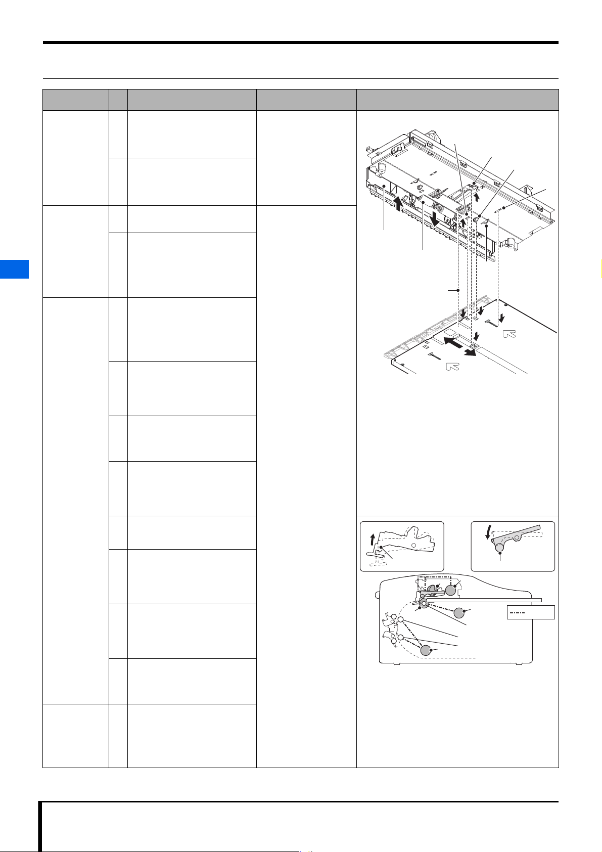
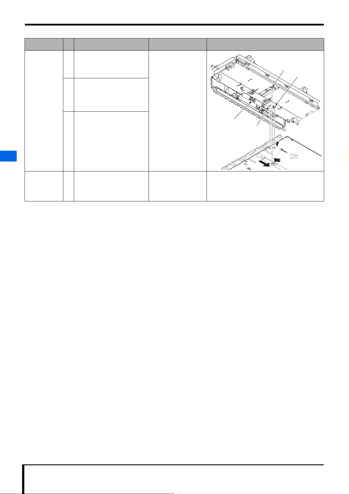
5.2.10 Removing & attaching the Sub-scan unit.......... 5-12
5.2.11 Removing and attaching the eraser unit ............ 5-17
5.2.12 Removing & attaching the exposure unit.......... 5-20
5.2.13 Removing & attaching light collection unit...... 5-21
5.2.14 Removing & attaching the upper door assy...... 5-23
5.3 Changing electrical parts............................................5-25
5.3.1 Changing the status LED board ......................... 5-25
5.3.2 Changing the LED drive2 board........................ 5-25
5.3.3 Changing the Eraser Unit Assy (Eraser LED).. 5-27
5.3.4 Changing the main board.................................... 5-28
5.3.5 Changing the SW power supply ........................5-30
5.3.6 Changing the power supply circuit breaker....... 5-31
5.3.7 Changing the Inlet-NF wiring Assy................... 5-32
5.3.8 Changing size detection sensors 1 and 2 ........... 5-33
5.3.9 Changing the cassette sensor.............................. 5-34
5.3.10 Changing the plate sensor (light receiving)....... 5-34
5.3.11 Changing the plate sensor (light emitting) ........5-35
5.3.12 Changing the V-SYNC sensor and V-SYNC
assembly............................................................... 5-37
5.3.13 Changing the entrance NIP sensor..................... 5-38
5.3.14 Changing the exit NIP sensor............................. 5-39
5.4 Changing mechanical parts.......................................5-40
5.4.1 Changing the loading/feeding motor ................. 5-40
5.4.2 Changing the sub-scan NIP motor and
sub-scan drive Assy............................................. 5-41
5.4.3 Changing the sub-scan feeding motor ............... 5-43
5.4.4 Changing the Eraser LED cooling fan............... 5-44
5.4.5 Changing the magnetic clutch............................ 5-45
5.4.6 Changing the upper door guide.......................... 5-46
5.4.7 Changing the link assemblies............................. 5-47
5.4.8 Changing the entrance guide.............................. 5-48
5.4.9 Changing the drive rollers................................... 5-49
5.5 Changing cassette parts ............................................5-51
5.5.1 Disassembling a cassette..................................... 5-51
8.2 Device Wiring Diagram ................................................8-9
8.2.1 REGIUS Device Wiring Diagram..............8-9
8.2.2 REGIUS II Device Wiring Diagram......... 8-10
Chapter 9 Revision History ................................ 9-1
9.1 Manual revision history.................................................9-2
Chapter 6 Adjustments ...................................... 6-1
6.1 Oblique adjustments ....................................................6-2
Chapter 7 Maintenance & Inspection................ 7-1
7.1 Maintenance/Inspection Schedule..............................7-2
7.2 Plate feeding path cleaning .........................................7-2
Chapter 8 Appendix ........................................... 8-1
8.1 Service Tool Screen (Unit test) ....................................8-2
8.1.1 [Unit test] Screen................................................... 8-2
8.1.2 [Unit Test] (Check) Screen................................... 8-3
8.1.3 [Error Hist] Screen ................................................ 8-7
8.1.4 [Warning setting] Screen....................................... 8-8
8.1.5 [Report of reader] Screen...................................... 8-8
2REGIUS /II Service Manual
Page 5

IMPORTANT
Introduction
The Direct Digitizer REGIUS and/or REGIUS II (called the
"device" hereinafter) is an X-ray image cassette reading device that
uses photostimulable phosphor as an X-ray detector.
This manual states the cautions and steps for service engineers to
perform repair or maintenance of this device (or a system including
this device).
After reading through this manual, make sure it is readily
accessible for future reference.
How to Read this Manual
Structure of This Manual
This manual is divided into the following 9 chapters describing
device repair and maintenance methods, as well as safety
precautions and operation.
Chapter 1: Safety Warnings & Cautions
An explanation of the safety warnings and cautions to follow while
repairing or maintaining this device.
Chapter 2: Before Repairing
An explanation of device fundamentals that need to be understood
before attempting to repair or maintain this device.
Chapter 3: Troubleshooting
An explanation of the various methods for dealing with devicerelated troubles.
Chapter 4: Using a Service Tool to Confirm Behavior
An explanation of how to confirm device operation.
Chapter 5: Disassembly & Assembly
An explanation of the steps needed to disassemble and assemble
the device.
Cautions
1) Unauthorized reproduction of any part of this manual is
prohibited.
2) The contents of this manual are subject to change without
notice.
3) Any discrepancies, errors or omissions noted should be
communicated to the manufacturer.
4) Notwithstanding item 3) above, the manufacturer accepts no
responsibility whatsoever for any loss or decrease in profi ts
arising from usage of the product.
Chapter 6: Making Adjustments
An explanation of part adjustments necessary for repair and
maintenance.
Chapter 7: Maintenance & Inspection
An explanation of how to maintain and inspect the device.
Chapter 8: Appendix
A list of technical information for reference during device repair or
maintenance.
Chapter 9: Revision History
Settings and behavior confirmation of the device are
performed with the service tools of REGIUS ImagePilot
(hereinafter ImagePilot).Service tool operation details
can be found in the ImagePilot Installation & Service
Manual, so you are recommended to refer to it when
necessary.
Trademarks
Company names and product names in this manual are trademarks
or registered trademarks of their respective owners.
©, ® and ™, representing these ownerships, are omitted in the
following pages.
Copyright © 2011 Konica Minolta Medical & Graphic, Inc. All
Rights Reserved.
REGIUS /II Service Manual i
Page 6
Difference between REGIUS and
REGIUS II
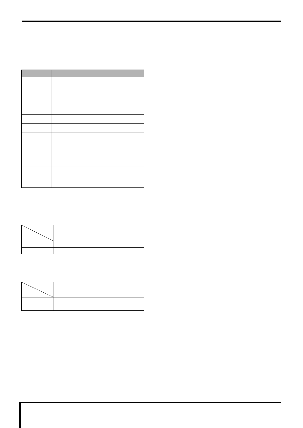
Parts changed
The following REGIUS parts are replaced in the REGIUS II.
Category Name Outline of the change
No.
1 Parts Front panel Logo (REGIUS II) is
2 Parts Rating plate -
printed
3 Parts Sensor on each
part_relay Assy
4 Parts LED_BOARD LED2_BOARD
5 Parts LED_DRIVE_BOARD LED_DRIVE2_BOARD
6 Parts FFC cable_Assy Number of pins,
7 Parts SW power supply -
MAIN_BOARD_Assy
8 Unit Eraser Unit
Pin-out
Connector connection
method
With a ferrite core
• LED2_BOARD
• LED_DRIVE2_BOARD
• FFC cable_Assy
Board Compatibility
Equipment and Board
• REGIUS can use both new and old boards.
• REGIUS is also be planned to be integrated in the new board.
Equipment
REGIUS
REGIUS II
Board
• LED_BOARD
• LED_DRIVE_BOARD
Old
• LED2_BOARD
• LED_DRIVE2_BOARD
New
LED and Drive Board
• The new and old boards are not compatible with each other when
combined.
Drive Board
LED
REGIUS
REGIUS II
ii REGIUS /II Service Manual
LED_DRIVE_BOARD LED_DRIVE2_BOARD
Page 7

1
Chapter
Chapter 1 Safety Warnings &
1
Precautions
An explanation of the safety warnings and cautions to follow while
repairing or maintaining this device.
1.1 Symbols relating to Safety ....................................................... 1-2
1.1.1 Safety Alert Symbol...................................................1-2
1.1.2 Warning Notice (Signal Words) ................................1-2
1.1.3 Description of Graphic Symbols ............................... 1-2
1.2 Warning Labels......................................................................... 1-3
1.3 Safety Precautions ................................................................... 1-4
1.3.1 Precautions Necessary to Follow Legal and
Regulatory Requirements ......................................... 1-4
1.3.2 General Precautions..................................................1-4
1.3.3 Handling Precautions................................................ 1-4
1.3.4 Precautions Relating to Handling
Cassettes/Plates........................................................1-4
1.3.5 Servicing Precautions................................................ 1-5
1.3.6 Disposal Cautions......................................................1-5
Safety Warnings & Precautions
Page 8
Chapter 1 Safety Warnings & Precautions
1.1 Symbols relating to Safety
1.1.1 Safety Alert Symbol
This is the "safety alert symbol." This symbol alerts
you to matters and/or operation potentially
hazardous to yourself and other people. Read these
messages and follow the instructions carefully.
1.1.2 Warning Notice (Signal Words)
Signal words indicate the degree of potential hazards in the use of
1
the product.
Signal words include the following three types, which are used
according to risk of damage caused by danger and the severity of
damage.
DANGER
Indicates a imminently hazardous situation which, if not avoided,
will result in death or serious injury.
WARNING
Indicates a potentially hazardous situation which, if not avoided,
could result in death or serious injury.
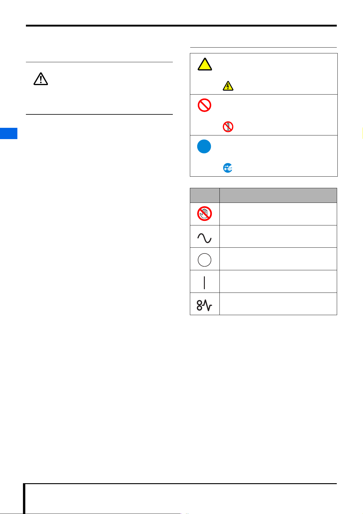
1.1.3 Description of Graphic Symbols
A triangle indicates a danger against which you
should take precaution.
e.g.)
This symbol warns against "Danger of
Electrical Shocks".
A diagonal line indicates a prohibited course of
action.
e.g.)
This symbol indicates you "Do Not
Disassemble".
A solid circle indicates an imperative course of
action.
e.g.)
This symbol indicates you must "Remove
Plug from Power Outlet".
Graphic
symbols
Indicates items that cannnot be touched.
Explanation
CAUTION
Indicates a potentially hazardous situation which, if not avoided,
could result in minor or moderate injury. It may also be used to
1.1 Symbols relating to Safety
indicate hazardous situation where only physical damage is likely
to occur.
Indicates that AC power is being used.
Indicates the off position for the main power switch
of this device.
Indicates the on position for the main power switch
of this device.
Indicates that a plate is jammed inside the device.
1-2 REGIUS /II Service Manual
Page 9
Chapter 1 Safety Warnings & Precautions
CAUTIONCAUTION
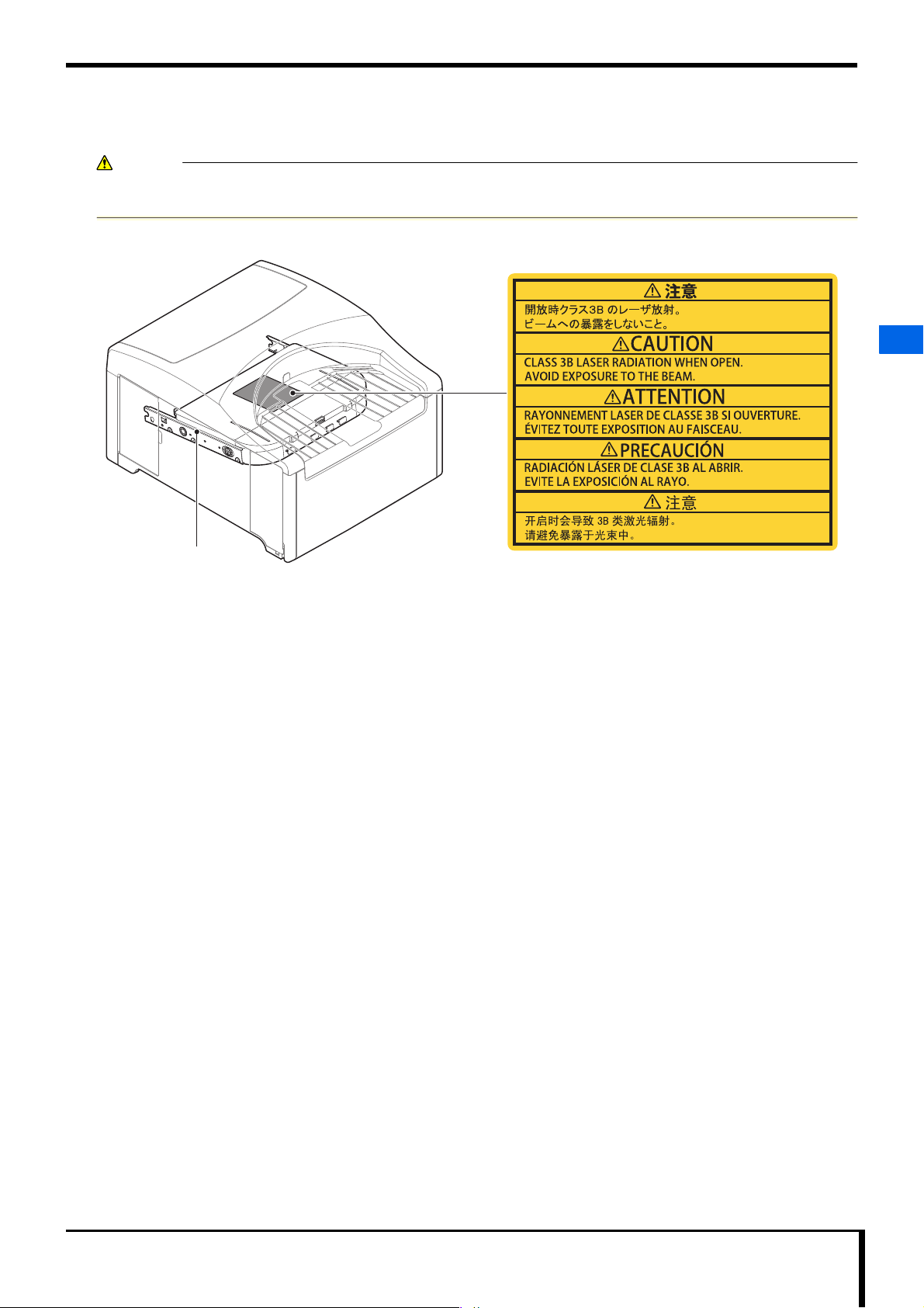
1.2 Warning Labels
Warning labels are attached to the following areas of the device.
Before performing maintenance such as installation or repair, make sure to fully understand the meaning of each warning
label, and how to handle each section they are located in.
Laser warning label
1
Exposure Unit
1.2 Warning Labels
REGIUS /II Service Manual 1-3
Page 10
Chapter 1 Safety Warnings & Precautions
1
1.3 Safety Precautions
1.3 Safety Precautions
Read all safety precautions thoroughly before using the device.
Be sure to observe the safety precautions described in this section.
1.3.1 Precautions Necessary to Follow Legal and Regulatory Requirements
CAUTION
Caution as to laser control
To prevent danger, make sure that only service engineers who
received proper formal training will remove the exterior cover or
touch the inside of the equipment.
Specifications of laser unit
Item Specifications
Class 3B
Medium Semiconductor laser
Wavelength 659 nm
Maximum output 130 mW
This device is a Class 1 laser product.
1.3.2 General Precautions
WARNING
Do not perform any work or operations that are not
•
described in this manual.
If you do accidentally conduct work not described in this
manual, you may suffer from burns or electric shock due to
touching a hot section or high voltage component of this
machine.
• Be sure to follow safety precautions for warning labels.
Be sure to follow the safety precautions contained in this
manual and shown on warning labels attached to this machine.
Failure to observe these precautions may result in personal
injury or damage to this machine.
• This device is equipped with a laser generator (class 3B).
Avoid exposing the eyes or skin to direct laser, as it could cause
a serious injury.
• Removing exterior covers
To prevent danger, make sure that only service engineers who
received proper formal training will remove the exterior cover
or touch the inside of the device.
1.3.3 Handling Precautions
WARNING
If unusual noises, odor, or smoke comes from this device,
•
stop operation.
If unusual noises, odor, or smoke coming from this device is
detected, immediately stop operation. If you continue to
operate it with the abnormal condition left as it is, it could
cause an electric shock, fire, or damage to the device.
• Be careful not to trip over or trample on the power cable.
If you continue to use the damaged cable, it could cause an
electric shock, heat generation or fire.
• Do not remove the power plug by pulling on the power
cable.
Doing so may cause the power cable to break, resulting in heat
generation or fire.
• Do not put drinks or foreign objects on the device.
Do not put drinks such as juice or foreign objects such as clips
and pins on this machine. If you use this device after liquids or
foreign objects such as metals have entered the machine, it can
cause a short in the internal circuit, resulting in fire.
CAUTION
Do not block air intakes or outlets of the device.
•
If air intakes or outlets of the device are blocked, it can cause
the device to fail or reduce the accuracy of image reading.
• Do not leave objects standing on the device or do not
step on it.
Doing so may lead to the risk of injury due to falling, or
damage the device.
• Do not use equipment such as mobile phones that emit
electromagnetic waves.
If you use equipment such as mobile phones that emit
electromagnetic waves near the device, it can have a negative
effect on the device.
1.3.4 Precautions Relating to Handling Cassettes/Plates
WARNING
Do not scratch the plate.
•
The photostimulable luminescent material used on the plate can
cause problems if it enters the human body. If the protective
layer on the plate surface has been severely damaged and the
photostimulable luminescent material is exposed, take the
following actions.
- If swallowed, consult a physician immediately.
- If the eyes are exposed to it, flush them with clean
water and consult a physician immediately.
- If the skin is exposed to it, rinse with clean water
immediately.
- Even if the photostimulable luminescent material does
not enter the human body, take preventive measures
against contact and dispose of the plate immediately in
accordance with the applicable standards.
1-4 REGIUS /II Service Manual
Page 11
1.3.5 Servicing Precautions
WARNING
Do not insert a piece of wire or metal.
•
Do not insert foreign objects such as metal strip or wire through
vent or gap in the main device. Doing so may result in electric
shock.
• Be sure to turn OFF when servicing.
Pulling the circuit board out of this machine or removing
connectors and cables while the power is turned on may result
in a serious accident. Make sure to turn off the power supply
circuit breaker before starting these operations.
CAUTION
When handling internal electronic components of the
•
device, wear a wristband.
When handling internal electronic components, wear an
antistatic wristband.
If you touch an electronic component such as circuit board with
an electrostaticallycharged hand, it can cause damage.
• Before cleaning, make sure to unplug the power supply,
or switch OFF the power supply circuit breaker.
Be sure to unplug or turn OFF the power switch before cleaning
this machine.
You could get your finger caught in sliding or rotating parts.
Chapter 1 Safety Warnings & Precautions
1
1.3 Safety Precautions
1.3.6 Disposal Cautions
CAUTION
Please follow the rules and regulations of your relevant
•
authorities in the disposal of this device, accessories,
options, consumables, media and their packing materials.
REGIUS /II Service Manual 1-5
Page 12

Blank Sheet
Page 13

Chapter
Chapter 2 Before Repairing
2
An explanation of device fundamentals that need to be understood before
attempting to repair or maintain this device.
2.1 Names of Parts......................................................................... 2-2
2.1.1 External View of the device....................................... 2-2
2.1.2 Status lamps............................................................... 2-3
2.2 Configuration............................................................................. 2-4
2.3 Main Specifications................................................................... 2-5
2.3.1 Device Specifications................................................. 2-5
2.3.2 Image Reading & Erasing......................................... 2-5
2.3.3 Control Part Functions...............................................2-7
2.4 Block Diagram ..........................................................................2-8
2.5 Main Part Locations.................................................................. 2-9
2.5.1 Frame......................................................................... 2-9
2.5.2 Upper Insertion Unit................................................. 2-10
2.5.3 Lower Insertion Unit................................................. 2-11
2.5.4 Sub-scan Unit ..........................................................2-12
2.5.5 Exposure Unit ..........................................................2-13
2.5.6 Light Collection Unit.................................................2-13
2.5.7 Eraser Unit ...............................................................2-14
2.6 Behavior Explained ................................................................2-15
2.6.1 State Transition Diagram.........................................2-15
2.6.2 Normal Operation (Image Reading).......................2-16
2.6.3 Initialization Operation.............................................2-19
2.6.4 Erase Operation.......................................................2-21
2.7 Cassette/Plate Handling ........................................................2-22
2.8 Tools, Instruments, Jigs, etc. Needed for Service ................2-22
2
Before Repairing
Page 14
Chapter 2 Before Repairing
3
2
6 7 98
12
1
11
10
5
4
15
16
13
8 14
1
1
17 18
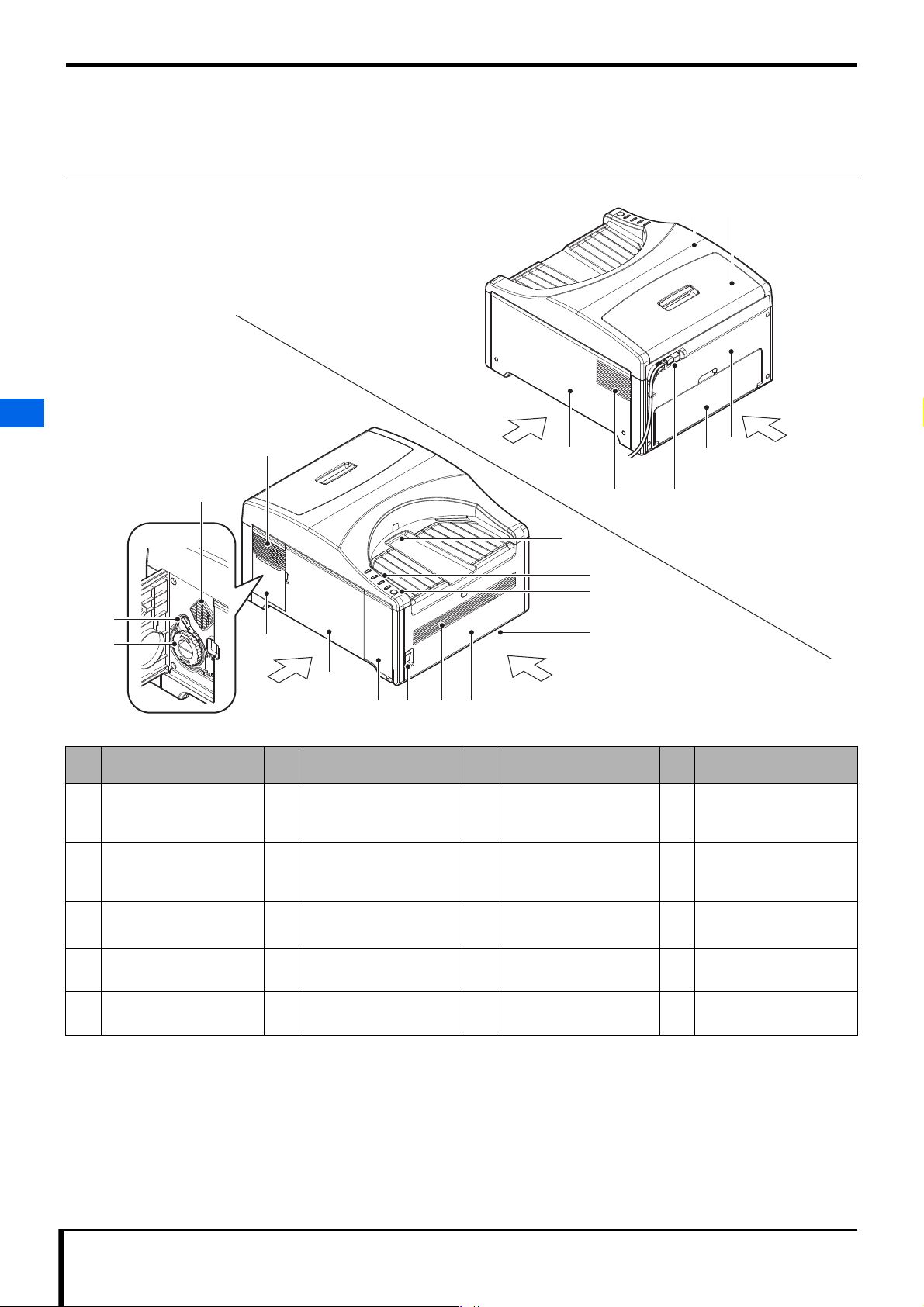
FrontLeft
RearRight
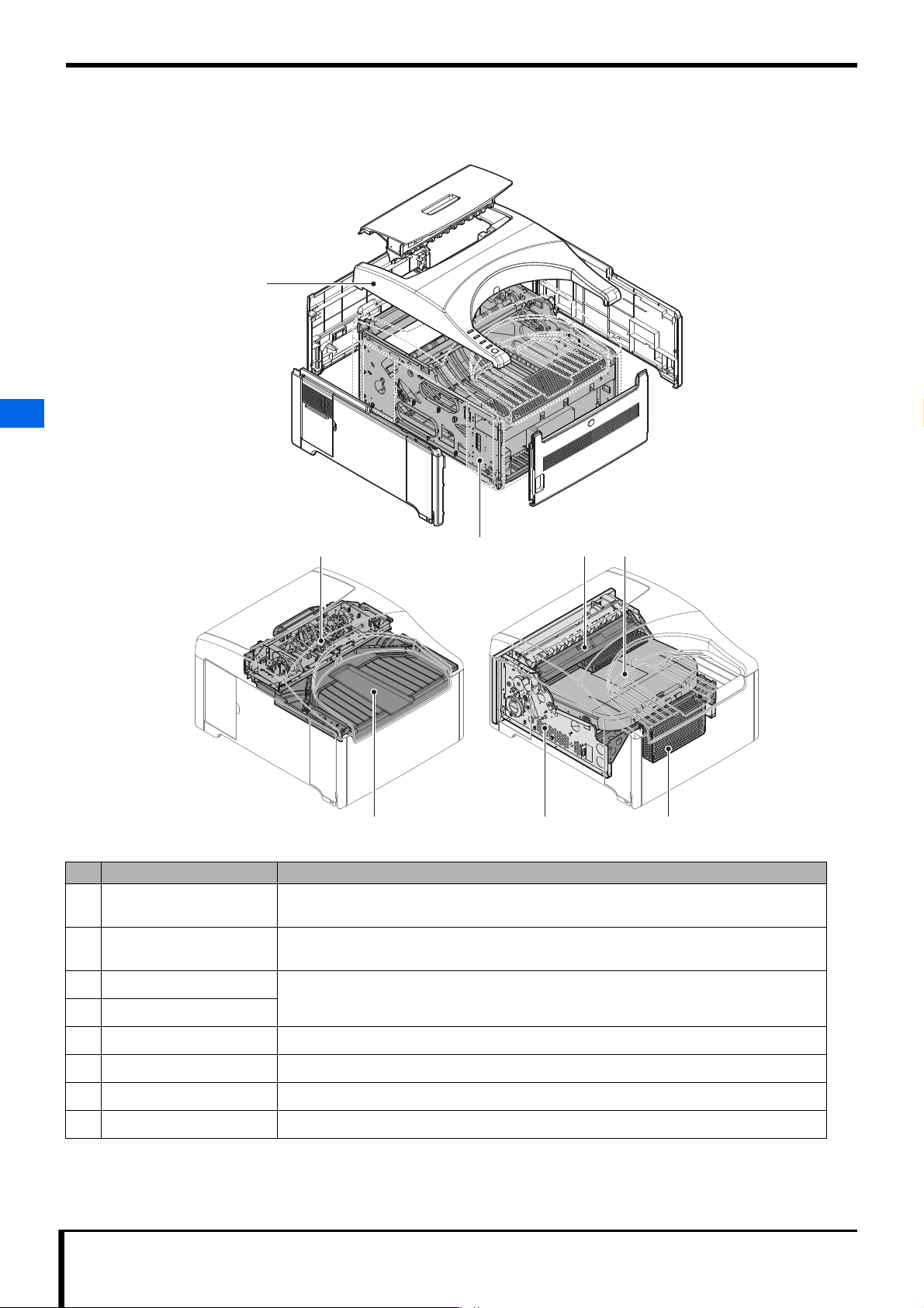
2.1 Names of Parts
Part names are indicated here that should be known in order to repair the device.
2.1.1 External View of the device
2
2.1 Names of Parts
No.
1 Intake vent 2 Light Collection Unit
5 Left side panel
9 Front panel
13 Right side panel
17 Upper cover
Common Name
(Part Name)
(Left side panel)
(Front panel Assy)
(Right side panel)
(Upper cover Assy)
No.
6 USB Cover
10 Cassette insertion slot 11 Status lamps
14 Power supply port
18 Upper Door
Common Name
(Part Name)
Cleaning Handle
(Handle)
(USB cover)
(Inlet-NF wiring Assy)
(Upper door Assy)
No.
3 Unjamming dial
7 Power supply circuit
Common Name
(Part Name)
(Handle)
breaker
(Circuit protector)
• Refer to Page 2-3.
15 Rear door
(Rear Assy)
No.
4 Left Door
8 Exhaust outlet
12 Erase button
16 Rear panel
Common Name
(Part Name)
(Left door Assy)
(Erase button)
(Rear panel patch Assy)
2-2 REGIUS /II Service Manual
Page 15
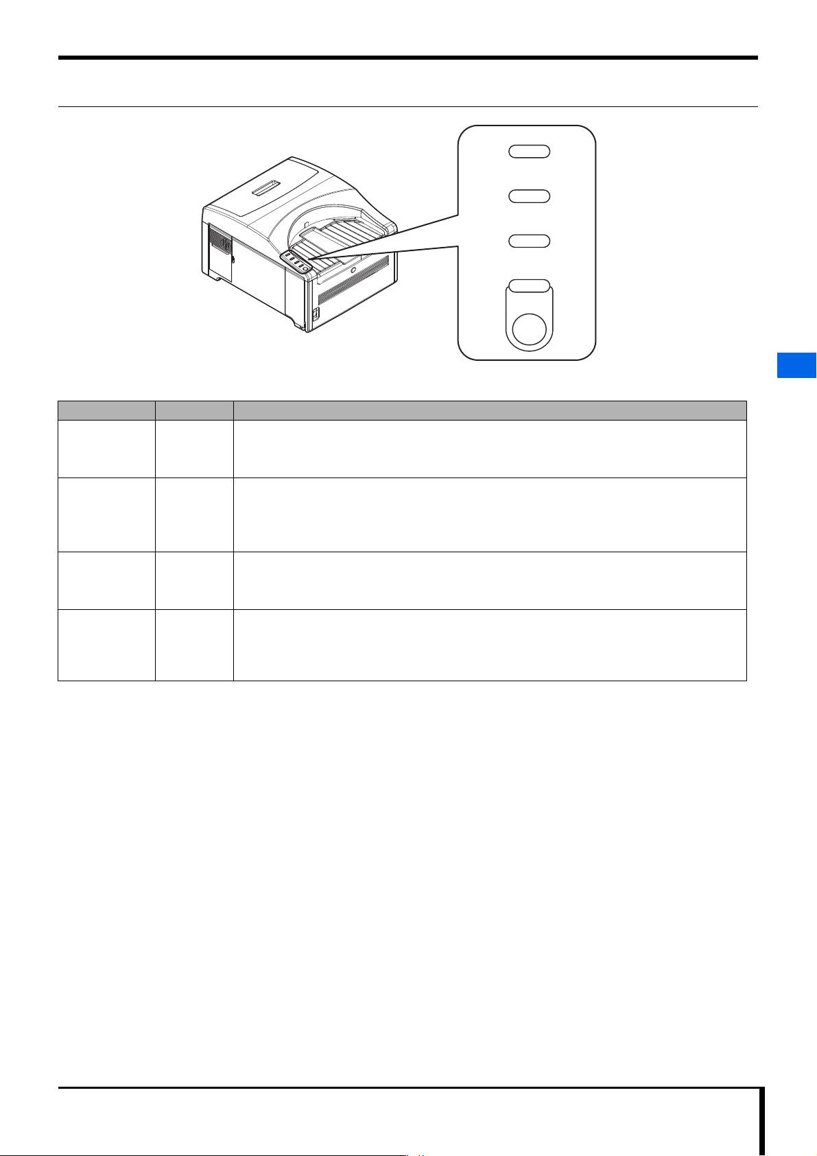
2.1.2 Status lamps
The 4 LEDs that indicate this device's current status are called "Status Lamps."
Name Color Function
Ready Lamp Green Indicates when a cassette is loaded or ejected.
• Lit: The cassette can be loaded.
• Blinking: The process has finished, and the cassette can be ejected.
Chapter 2 Before Repairing
Ready
Busy
Error
Erase
2
Busy Lamp Blue Indicates the process status.
• Lit: Process in progress.
• Blinking: Preparing to start process (inspection questions during image reading)
• Unlit: The process has stopped.
Error Lamp Yellow Indicates error and warning status.
• Lit: Warning status alert, or connection with ImagePilot not established.
• Blinking: Error status alert
Erase Lamp Orange Indicates Erase Mode status.
• Lit: Image erase in progress, or the Erase switch is being pressed.
• Blinking: Image erase mode is selected, and device is in standby mode for cassette loading (5
seconds).
2.1 Names of Parts
REGIUS /II Service Manual 2-3
Page 16
Chapter 2 Before Repairing
2.2 Configuration
A description of how the device is configured.
1
2
2.2 Configuration
3
4 85
No. Name Function
1 External Unit Protects the device's interior parts from light, vibration, and other outside influences.
2 Frame Make up the device's frame.
3 Upper Insertion Unit Has a mechanism to release the loaded cassette's lock, and to eject or return the plate to normal.
4 Lower Insertion Unit
It is made up of a upper panel, side panels, and a door for accessing interior parts of the device.
Control parts, an inlet for power supply, and power sources are also included.
Display and operational parts are also included.
2
76
5 Sub-scan Unit Feeds the plate (with sub scan).
6 Eraser Unit Erases any image information remaining on the plate.
7 Exposure Unit Scan excited laser light for the plate.
8 Light Collection Unit Gathers phosphor light generated from the plate and converts it into electric signals.
2-4 REGIUS /II Service Manual
Page 17
Chapter 2 Before Repairing
IMPORTANT
IMPORTANT
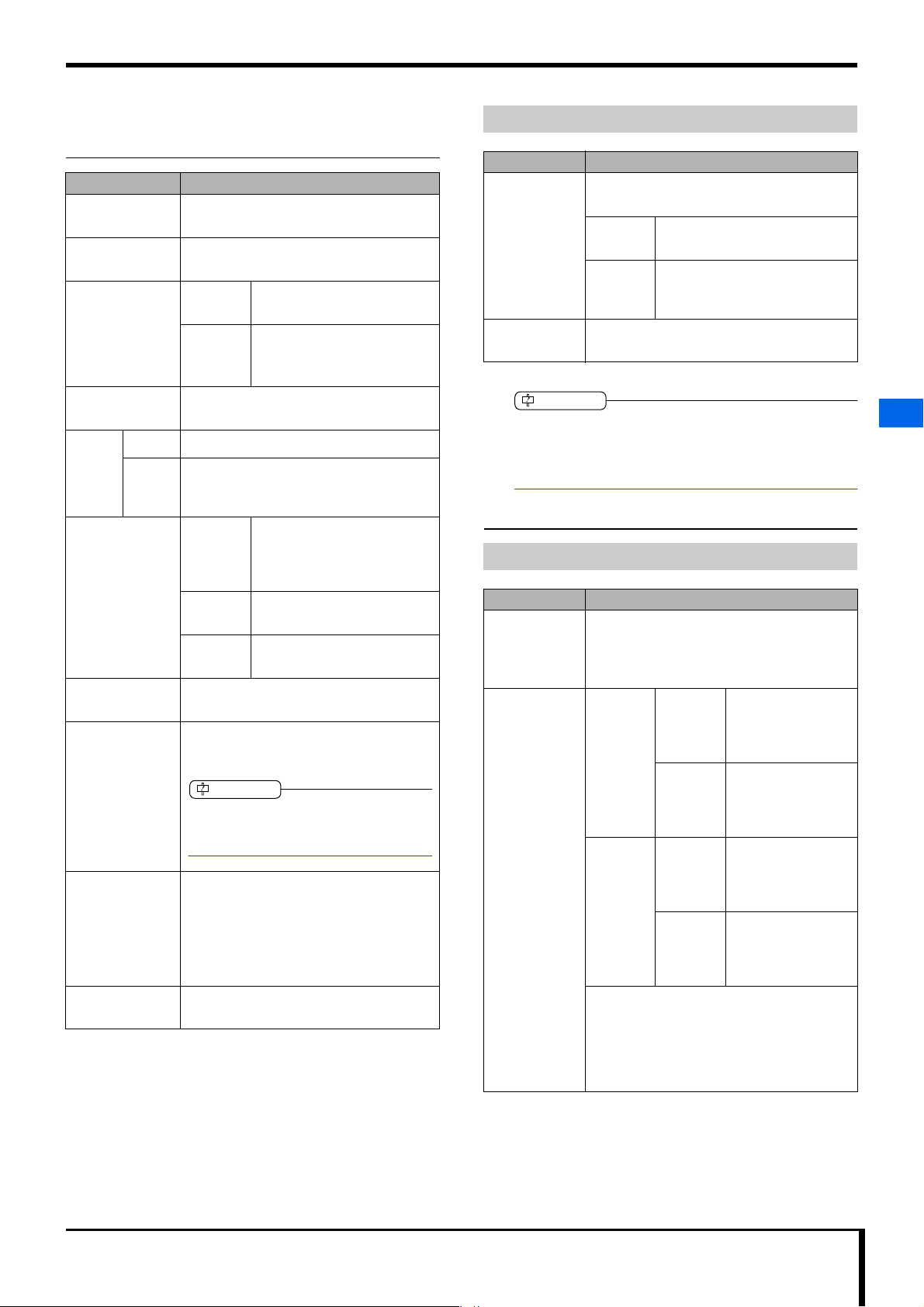
2.3 Main Specifications
2.3.1 Device Specifications
Item Content
External
dimensions
Mass Approximately 28 kg (excluding cassette
Noise level
(Excluding noise
originating from
user operation
(such as cassette
loading).)
Maximum power
consumption
Power
source
Hygrothermal
environment
External
connection
Service life 7 years (10 cassettes per day × 25 days per
Accessories • Power cable (length: 3 m)
Japan 100 V ± 10% (50/60 Hz)
Other
areas
510 (W) × 610 (D) × 355 (H) mm
and plate)
During
operation
During
standby
100 VA or less (100 V, 1 A or less)
115/120 V ± 10% (60 Hz)
110/220/230/240 V ± 10%(50/60 Hz)
200 V ± 10% (50 Hz)
Transport
packing
status
During
operation
When not
operating
USB 2.0 (Konica Minolta independent
communications specifications)
month × 12 months per year × 7 years =
21,000 cassettes)
User should consider service life 6 years. (A 6year service life is also mentioned in the
operation manual.)
Average = 53 dB or less
Maximum = 61 dB or less
Average = 25 dB or less
-20 to 60 ℃ / 90% RH or less
(no condensation)
0.7 to 1.0 atmospheric pressure
(= 709 to 1013 (hPa))
10 to 30 ℃ / 15 to 80% RH
(no condensation)
-10 to 40 ℃ / 90% RH or less
(no condensation)
• USB Cable
(length: 5 m, USB 2.0 High Speed
compatible)
• Operation manual
• Opening tools for cassette
Compatible Cassettes & Plates
Item Content
Readable
cassette
types
Readable plate
types
RC-300 cassettes with isolated open/close
structures and equivalent
Japan 14" × 17", 14" × 14", 11" × 14",
10" × 12", 8" × 10", 15cm × 30 cm
Other
areas
Regius Plate FP-1S or equivalent
14" × 17", 14" × 14", 11" × 14",
10" × 12", 8" × 10", 24cm × 30 cm,
18cm × 24 cm, 15cm × 30 cm
Cassettes/plates that can be used with this device are
device exclusive. Rigid type cassettes used with the
REGIUS MODEL 110, etc. cannot be used for this
device.
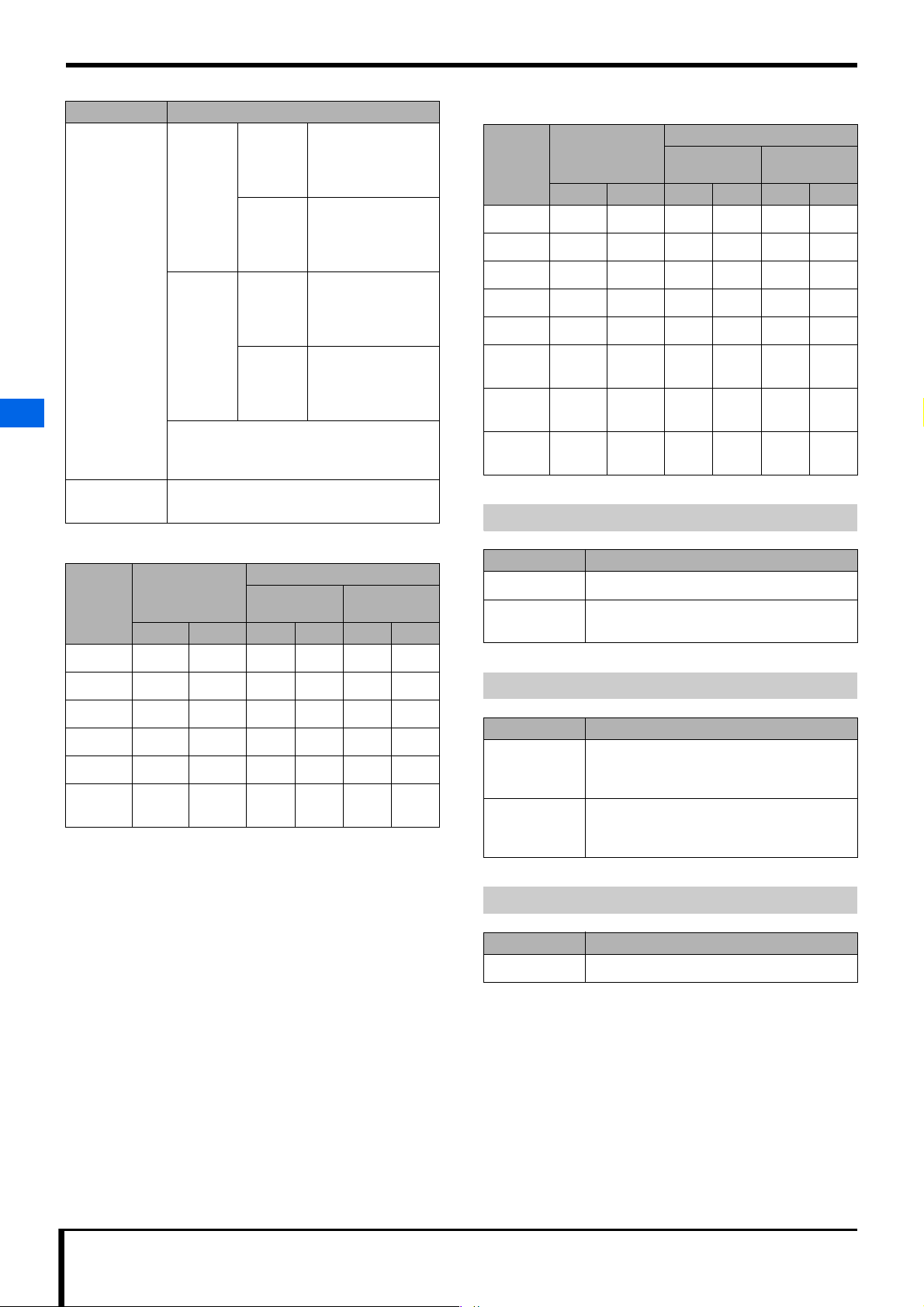
2.3.2 Image Reading & Erasing
Processing Ability
Item Content
Reading
resolution
Cycle time REGIUS Japan Up to 75 seconds
Normal read mode (175 µm)
High-definition read mode (87.5 µm)
• According to ImagePilot licensing. There
are no resolution settings for this unit.
per cassette
(14" × 14" / normal
read mode)
REGIUS
II
Other
areas
Japan Up to 54 seconds
Other
areas
Up to 80 seconds
per cassette
(14" × 17" / normal
read mode)
per cassette
(14" × 14" / normal
read mode)
Up to 60 seconds
per cassette
(14" × 17" / normal
read mode)
2
2.3 Main Specifications
Parts requiring
periodic change
None
• The fastest time from the cassette being
loaded and locked, to the end of the reading
process when the cassette is removed. The
fastest erase speed for standard dose
exposure. Cassette replacement time = 0
seconds.
REGIUS /II Service Manual 2-5
Page 18
Chapter 2 Before Repairing
Item Content
Processing
Ability
2
REGIUS Japan About 48 cassettes
Other
areas
REGIUS
II
Japan About 66 cassettes
Other
areas
per hour
(14" × 14" / normal
read mode)
About 45 cassettes
per hour
(14" × 17" / normal
read mode)
per hour
(14" × 14" / normal
read mode)
About 60 cassettes
per hour
(14" × 17" / normal
read mode)
• When continuous cassette loading, for the
number of cassettes going through the
process per hour.
Digital
gradation level
12-bit (4096 gradation)
Read image size (Other areas)
Cassette
type
14" 17" 365.75 442.05 2090 2526 4180 5052
14" 14" 365.75 365.75 2090 2090 4180 4180
11" 14" 289.10 365.75 1652 2090 3304 4180
10" 12" 264.25 315.35 1510 1802 3020 3604
8" 10" 213.50 264.25 1220 1510 2440 3020
24 cm
30 cm
18 cm
24 cm
15 cm
30 cm
Read capacity
(mm)
X way Y way X way Y way X way Y way
250.25 310.10 1430 1772 2860 3544
190.40 250.25 1088 1430 2176 2860
310.45 160.30 1774 916 3548 1832
Read pixel count
Normal read
mode
High-definition
read mode
Exposure Unit
Read image size (Japan)
Cassette
type
2.3 Main Specifications
14" 17" 365.75 442.05 2090 2526 4180 5052
X way Y way X way Y way X way Y way
Read capacity
(mm)
Read pixel count
Normal read
mode
High-definition
read mode
Item Content
Method Laser scanning by polygon mirror
Laser
wavelength
659 5 nm
14" 14" 365.75 365.75 2090 2090 4180 4180
11" 14" 289.10 365.75 1652 2090 3304 4180
10" 12" 264.25 315.35 1510 1802 3020 3604
8" 10" 213.50 264.25 1220 1510 2440 3020
15 cm
30 cm
310.45 160.30 1774 916 3548 1832
Light Collection Unit
Item Content
Method Light collecting mirror + reed-shaped light
guide + angled excitation light cut filter +
rounded photomultiplier tube (PMT)
Excitation light
elimination
An angled excitation light cut filter is placed in
the light guide window to eliminate excitation
light.
Eraser Unit
Item Content
Method Erasing done by white LED.
2-6 REGIUS /II Service Manual
Page 19
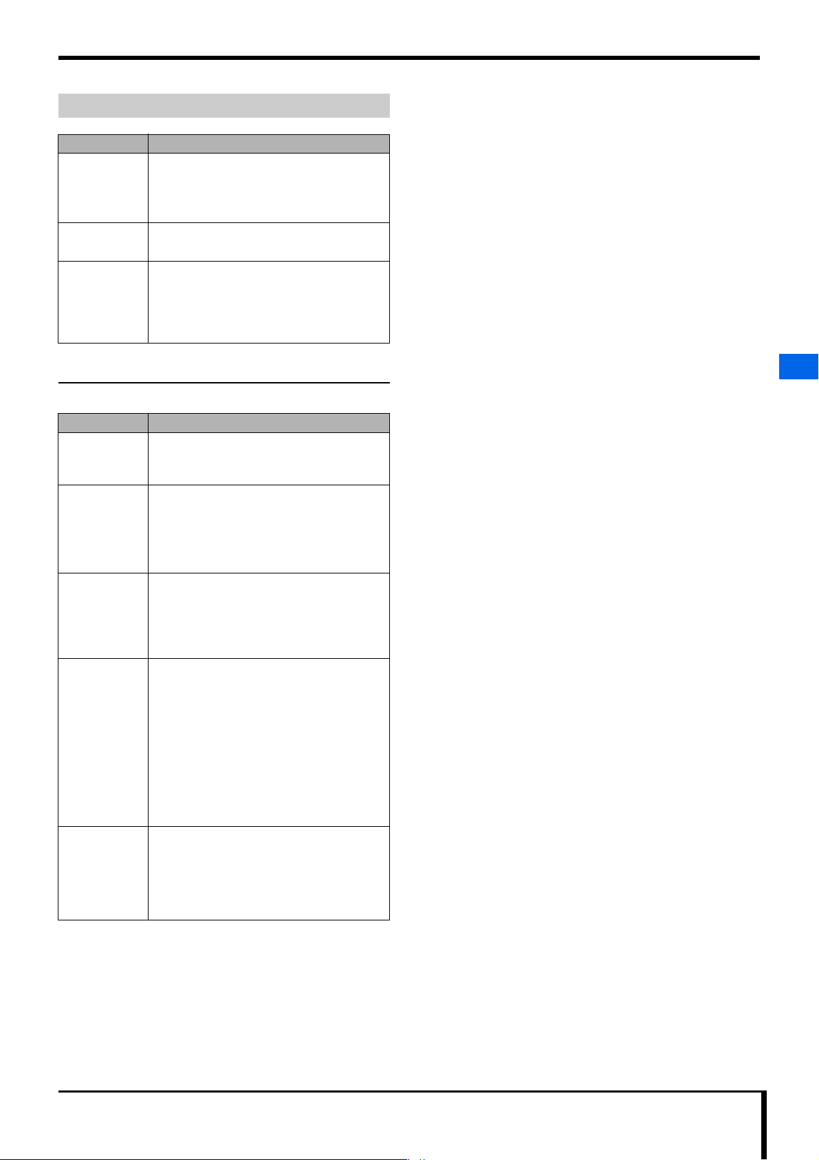
Sub-scan Unit
Item Content
Method Exposure unit fixed plate feed method
• Sub-scan (read/erase) of feeded
photostimulable phosphor plate by optical/
light collection unit.
Chapter 2 Before Repairing
Driving method The sheet-type plate roller feed method using
Operation
a 3-phase stepping motor.
• When reading:
reading is outward, erasing is out and back.
• When erasing:
reading is outward (max signal value
confirmation), erasing is out and back.
2.3.3 Control Part Functions
The main control part functions are as follows.
Function name Content
Image data
generation
function
Image data
revision/
calculation
function
Communication
function
• This function generates image data via laser
scanning.
• Moire elimination calculation
• Gain/offset revision calculation
• Shading irregularity correction, polygon
revision
• Erase speed calculation
• Command receiving function
• This function transmits read image data to a
console PC.
• This function provides a device status
notification.
2
2.3 Main Specifications
Control
function
Calibration
function
(during
maintenance/
shipment
settings)
• This function is triggered by cassette
loading, and performs a series of controls
including mechanical control, optical control,
signal processing control, communication
control, etc.
• This function performs the controls needed
to execute commands received via USB 2.0
interface communication.
• This function saves the base board serial
number to device memory which should
recognize the device's uniqueness.
Mainly the following functions are performed.
• Gain/offset function
• Irregularity calibration function
• Sensitivity calibration function
• Image position/size adjustment function
REGIUS /II Service Manual 2-7
Page 20
Chapter 2 Before Repairing
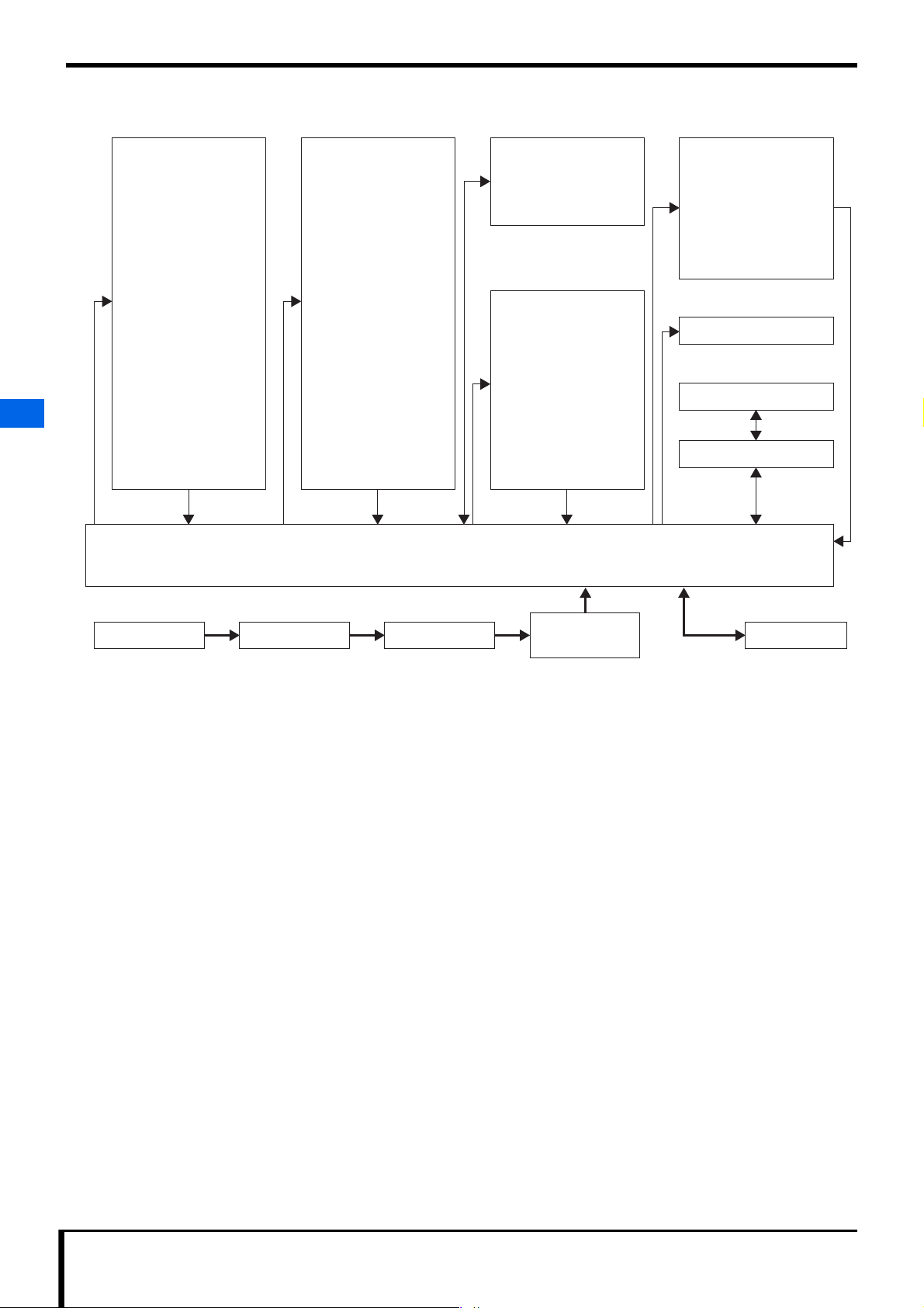
2.4 Block Diagram
2
2.4 Block Diagram
<Upper Insertion Unit>
Tray Moving Motor
Loading NIP Motor
Size Detecting Sensor 3
Size Detecting Sensor 4
Left Cassette Lock Sensor
Right Cassette Lock Sensor
Loading NIP HP Sensor
Loading NIP Open/Close Sensor
Tray Lock Release Sensor
Plate Sensor (light emitting)
Tray Sensor
Tray HP Sensor
Upper Door Interlock SW
AC100V to 240V
<Frame>
Eraser LED Cooling Fan
Magnetic Clutch
Loading/Feeding Motor
Left Door Open/Close Detection Sensor
Plate Sensor (light receiving)
Cassette Sensor
<Lower Insertion Unit>
Size Detecting Sensor 1
Size Detecting Sensor 2
MAIN_BOARD
LED_DRIVE2_BOARD
DC24/5V
Sub-scan NIP Motor
Sub-scan Feeding Motor
Entrance NIP Sensor
Rear Door Interlock SW
<Eraser Unit>
LED2_BOARD
<Sub-scan Unit>
V-SYNC Sensor
Exit NIP Sensor
SW power supply
<Exposure Unit>
LD_DRIVE_BOARD
LD_BOARD
H-SYNC_BOARD
Polygon
(DC24V)
STATUS_LED_BOARD
Photomultiplier Tube
ANALOG_BOARD
DC24V
External IF
USB24V
ImagePilot PCAC Power Source Inlet Noise Filter
Excluding what is listed in the diagram, motors are supplied 24V, and other devices are supplied 5V of electricity from the main board.
2-8 REGIUS /II Service Manual
Page 21
2.5 Main Part Locations
This is an explanation of where each device's main parts are positioned and how they function.
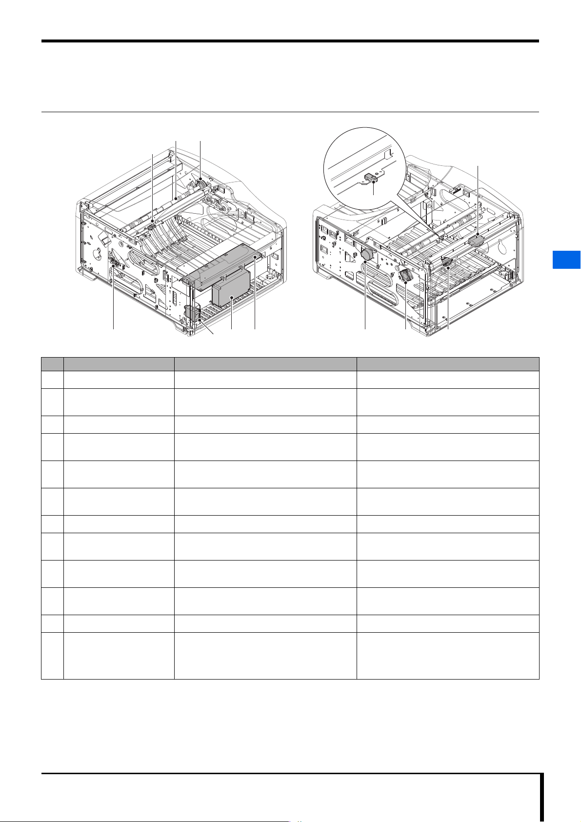
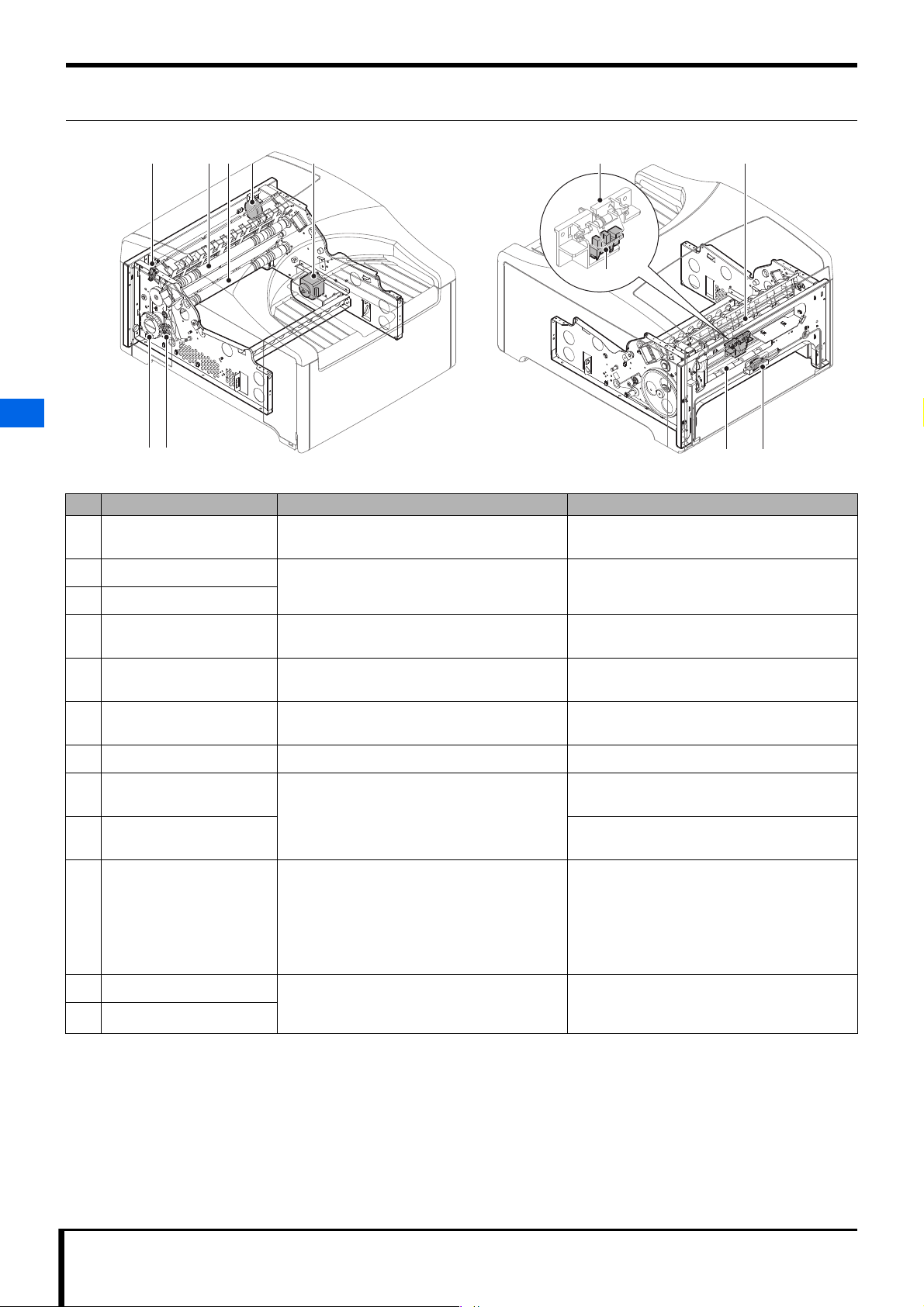
2.5.1 Frame
32
1
Chapter 2 Before Repairing
11
12
2
5 6 9 1084
No. Name Function Reference for how to change
1 Cassette Sensor Turned ON when the cassette is loaded. "5.3.9 Changing the cassette sensor (Page 5-34)"
2 Feeding Roller The loading/feeding motor operates to remove or
insert the plate from/into the cassette.
3 Magnetic Clutch Regulates power sent to feeding roller. "5.4.5 Changing the magnetic clutch (Page 5-45)"
4 Left Door Open/Close
Detection Sensor
5 Power supply circuit breaker Used to turn the device's power ON/OFF. "5.3.6 Changing the power supply circuit breaker
6 SW power supply - "5.3.5 Changing the SW power supply (Page 5-
7 MAIN_BOARD A base board that controls the device. "5.3.4 Changing the main board (Page 5-28)"
8 Insertion feed motor Removes or inserts the plate from/into the
9 Eraser LED Cooling Fan Takes in outside air to keep the eraser unit LED
10 Inlet-NF wiring Assy - "5.3.7 Changing the Inlet-NF wiring Assy (Page 5-
Turned ON when the left door is open. -
cassette.
cool.
7
"5.4.5 Changing the magnetic clutch (Page 5-45)"
(Page 5-31)"
30)"
"5.4.1 Changing the loading/feeding motor (Page
5-40)"
"5.4.4 Changing the Eraser LED cooling fan (Page
5-44)"
32)"
2.5 Main Part Locations
11 Noise filter - -
12 Plate Sensor (light receiving) Works together with the plate sensor (light
emitting) of the upper insertion unit to detect
whether a plate exists or not. Turns ON when a
plate exists.
"5.3.10 Changing the plate sensor (light receiving)
(Page 5-34)"
REGIUS /II Service Manual 2-9
Page 22
Chapter 2 Before Repairing
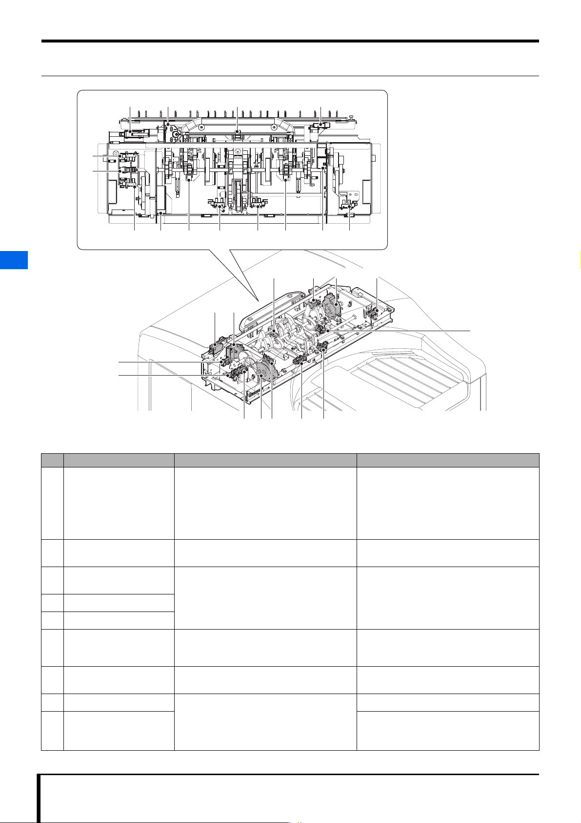
2.5.2 Upper Insertion Unit
1 2 10 11
3
4
5 7 13126 8 9 14
2
10
1 2
1311 14
2.5 Main Part Locations
12
3
4
65 9
No. Name Function Reference for how to change
1 Switch (interlock 1) Turned OFF when the upper door is open.
This is not a safety interlock, but when turned
OFF, power is disconnected from the following.
87
-
• Mechanical control power for motors, fans, etc.
• Eraser LED, power for high-voltage generation
• LD power
2 Adjusting cam, adjusting
board
3 Loading NIP Open/Close
Sensor
4 Tray Lock Release Sensor
5 Loading NIP HP Sensor
Used for oblique adjustments.
Refer to "6.1 Oblique adjustments (Page 6-2)".
Detects NIP status, the tray's lock status, etc.
when the plate is moving in and out of the
cassette.
Refer to "4.4.3 Insertion site sensor status (Page
4-6)".
Not changed as a single unit.
-
6 Insertion nip motor Performs NIP operation, or moves the tray's
abutment plate up and down when the image
plate is moving in and out of the cassette.
7 Left Cassette Lock Sensor Turned ON when the cassette is locked on the left
side.
8 Size Detection Sensor 4 Determines cassette size in a group of 4 sensors
9 Size Detection Sensor 3 Not changed as a single unit.
together with size detection sensors 1 and 2 of the
lower insertion unit.
Refer to "4.4.2 Cassette size & sensor status
(Page 4-5)".
Not changed as a single unit.
Not changed as a single unit.
Not changed as a single unit.
2-10 REGIUS /II Service Manual
Page 23
Chapter 2 Before Repairing
1
3
2
No. Name Function Reference for how to change
10 Plate Sensor (light emitting) Works together with the frame's plate sensor (light
receiving) to detect whether a plate exists or not.
"5.3.11 Changing the plate sensor (light emitting)
(Page 5-35)"
11 Tray Sensor Turned ON when the tray is outside of the
cassette.
12 Right Cassette Lock Sensor Turned ON when the cassette is locked on the
right side.
13 Casette tray move motor Moves the tray in and out, and corrects cassette
tilt.
14 Tray HP Sensor Turned ON when the notches used for moving the
tray in and out are in their home position.
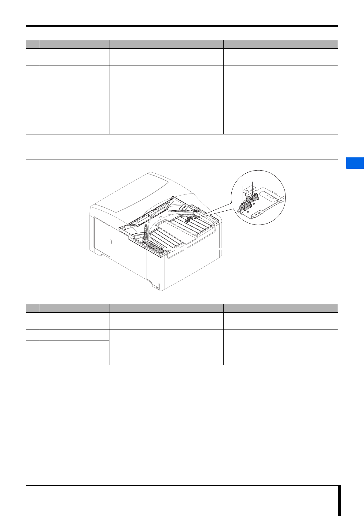
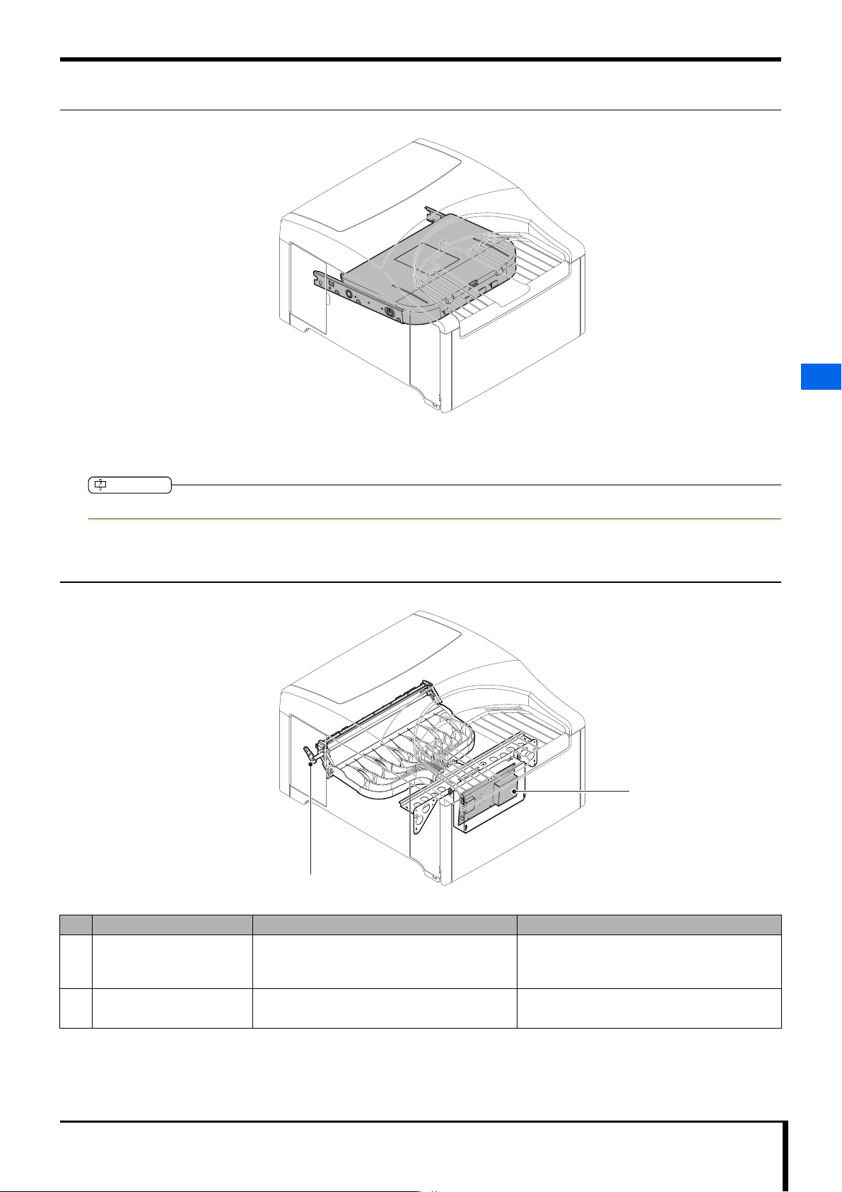
2.5.3 Lower Insertion Unit
Not changed as a single unit.
Not changed as a single unit.
Not changed as a single unit.
-
2
No. Name Function Reference for how to change
1 Status LED board A base board for status display (status lamps) and
operations (Erase switch).
2 Size Detection Sensor 1 Determines cassette size in a group of 4 sensors
3 Size Detection Sensor 2
together with size detection sensors 3 and 4 of the
upper insertion unit.
Refer to "4.4.2 Cassette size & sensor status
(Page 4-5)".
"5.3.1 Changing the status LED board (Page 5-
25)"
"5.3.8 Changing size detection sensors 1 and 2
(Page 5-33)"
2.5 Main Part Locations
REGIUS /II Service Manual 2-11
Page 24
Chapter 2 Before Repairing
2.5.4 Sub-scan Unit
5 8111 2 3 4
12
2
2.5 Main Part Locations
76
No. Name Function Reference for how to change
1 Entrance NIP Sensor Turned ON when Drive Roller U is in NIP status. "5.3.13 Changing the entrance NIP sensor (Page
5-38)"
2 Drive Roller U Feeds the plate via a Sub-scan Feeding Motor. "5.4.9 Changing the drive rollers (Page 5-49)"
3 Drive Roller D
4 Sub-scan NIP Motor Performs NIP for Drive Roller U and Drive Roller D."5.4.2 Changing the sub-scan NIP motor and sub-
scan drive Assy (Page 5-41)"
5 Sub-scan Feeding Motor Feeds the plate. "5.4.3 Changing the sub-scan feeding motor
6 Handle
(Unjamming dial)
7 Exit NIP Sensor Turned ON when Drive Roller D is in NIP status. "5.3.14 Changing the exit NIP sensor (Page 5-39)"
8 Driven entrance assembly -
driven roller
9 Driven exit assembly - driven
roller
10 Switch (interlock 2) Turned OFF when the rear door is open.
Used to rotate Drive Rollers U and D when a plate
jam occurs.
Operates via Sub-scan NIP motor to perform NIP
for Drive Roller U and Drive Roller D.
This is not a safety interlock, but when turned
OFF, power is disconnected from the following.
(Page 5-43)"
9 10
-
-
-
-
• Mechanical control power for motors, fans, etc.
• Eraser LED, power for high-voltage generation
• LD power
11 V-SYNC assembly Detects when passage is available for the plate in
12 V-SYNC Sensor
a reading area.
Sensor is ON when a plate exists.
2-12 REGIUS /II Service Manual
"5.3.12 Changing the V-SYNC sensor and VSYNC assembly (Page 5-37)"
Page 25
Chapter 2 Before Repairing
IMPORTANT
2.5.5 Exposure Unit
Parts within the exposure unit cannot be changed individually. If a problem occurs within the exposure unit, the entire exposure unit must be
changed.
2
Do not disassemble the exposure unit.
2.5.6 Light Collection Unit
2.5 Main Part Locations
2
1
No. Name Function Reference for how to change
1 Handle
(Light Collection Unit
Cleaning Handle)
2 Analog board A base board that takes in analog signals from the
Activates a cleaning mechanism to keep the light
guide and laser scanning line of the light collection
unit free of dust.
photomultiplier tube and converts them.
REGIUS /II Service Manual 2-13
"5.2.10 Removing & attaching the Sub-scan unit
(Page 5-12)"
Not changed as a single unit.
Page 26
Chapter 2 Before Repairing
1
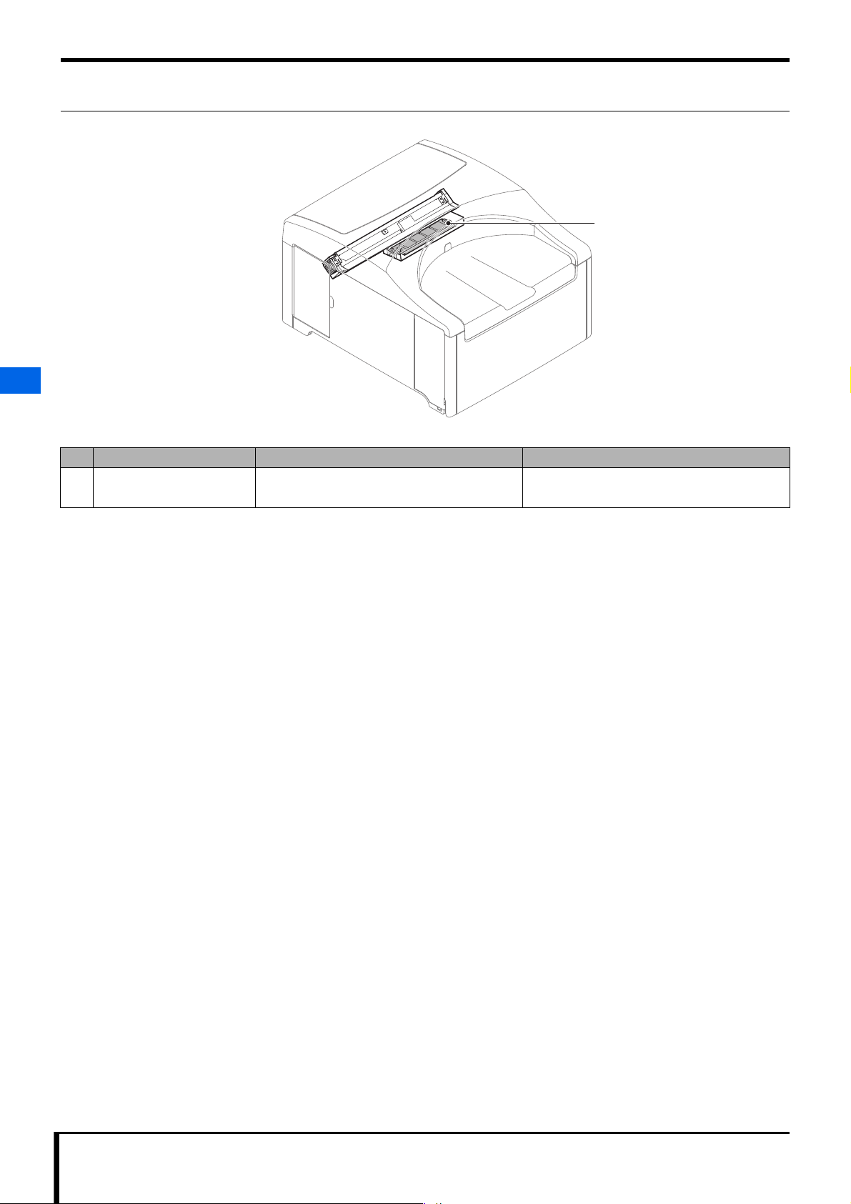
2.5.7 Eraser Unit
2
No. Name Function Reference for how to change
1 LED_DRIVE2_BOARD A base board that controls the Eraser LED. "5.3.2 Changing the LED drive2 board (Page 5-
25)"
2.5 Main Part Locations
2-14 REGIUS /II Service Manual
Page 27
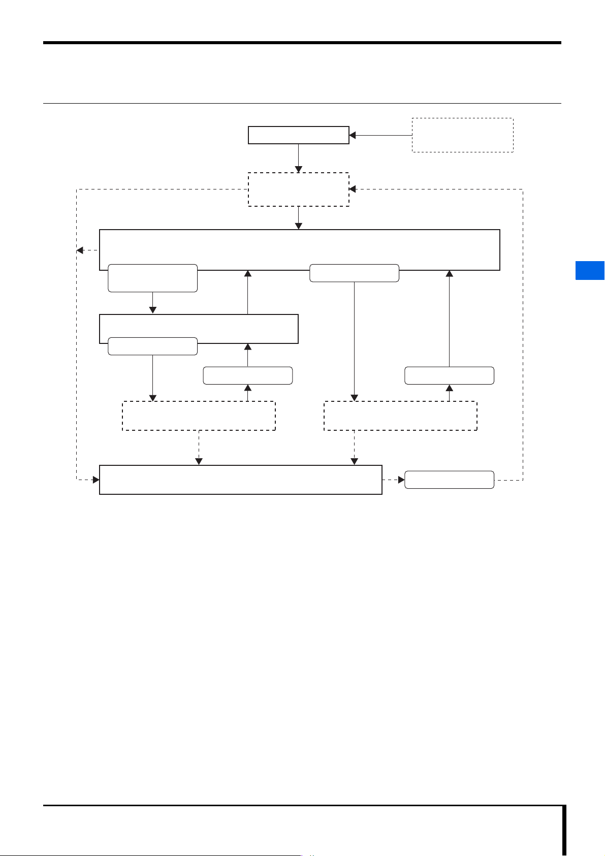
2.6 Behavior Explained
Power Supply Circuit Breaker ON
Power Supply Circuit Breaker OFF
(Constant)
Cassette Ejected
Cassette Inserted
Erase Switch
pressed for 2 seconds
Cassette Inserted
Door Opened/Closed
Cassette Ejected
Routine Mode
Boot
Initialization Process
Erase Mode
Erase Process
Error Occurs
Image Reading
2.6.1 State Transition Diagram
Chapter 2 Before Repairing
2
No sleep mode as with REGIUS MODELS 110/210 is available. (No operation switch.)
2.6 Behavior Explained
REGIUS /II Service Manual 2-15
Page 28
Chapter 2 Before Repairing
B
C
D
A
E
Upper Insertion Unit
Cassette
8
10
11
6
12
4
1
22
7
3
5
Abutment Plate
NIP Roller
Size Detection Sensor 3
9 ON
13 ON
13 ON
10
11
Feeding Roller
Drive Roller U
Drive Roller D
J
I
H
NIP Roller
Abutment Plate
F
G
Power
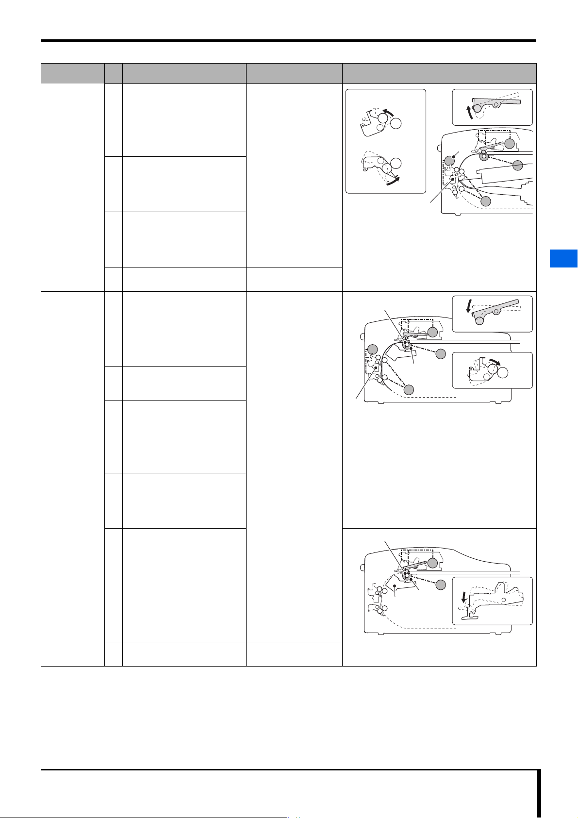
2.6.2 Normal Operation (Image Reading)
Operation/
Initialization
User loads
cassette
2
Plate is ejected
2.6 Behavior Explained
Plate is sent
(feed)
2-16 REGIUS /II Service Manual
control
No.
Feed (letters in parenthesis
correspond to the diagram)
1 Notch (A) for tray removal
retracts.
• Drive source: Tray moving
motor (F)
2 The tray's lock release Notch (B)
retracts.
• Drive source: Loading NIP
motor (G)
3 Notch (C) locks the cassette.
• No drive source
4 Notch (D) releases tray lock (bolt
mechanism). (For large
cassettes only)
• No drive sourcePart (E) is
pushed into operation by the
cassette.
5 Notch (A) is lowered, and
connects to the cassette's tray
ejection notch (cassette open/
close lever).
• Drive source: Loading NIP
motor (G)
6 Notch (A) moves in the tray's
return direction and corrects the
cassette's position.
• Drive source: Tray moving
motor (F)
7 Notch (B) is lowered, and the tray
lock is released.
• Drive source: Loading NIP
motor (G)
8 Notch (A) ejects the tray, and
bumps it against the abutment
plate.
• Drive source: Tray moving
motor (F)
9 Magnetic Clutch (H) is turned
ON. (Feeding roller connects to
drive source.)
10 The NIP roller is lowered, and
moves into NIP status with the
feeding roller.
• Drive source: Loading NIP
motor (G)
11 The abutment plate is raised with
the tray attached, and the image
plate is removed from the tray.
• Drive source: Loading NIP
motor (G)
12 Notch (A) slightly returns the tray
(to avoid tray and roller contact).
• Drive source: Tray moving
motor (F)
13 Loading/Feeding Motor (I) starts
the plate into send feed.
At the same time, Sub-scan
Feeding Motor (J) starts up.
• Drive source: Loading/
Feeding Motor (I)
Exposure / Optical /
Eraser
• Polygon starts to
rotate for cassette
detection.
• Seven seconds later,
the polygon lock is
confirmed, the laser
emits low level light,
and PMT high voltage
is turned ON. (PMT
voltage level rises until
V-SYNC detection)
Diagram (Numbers here correspond with the "No."
column)
Page 29
Chapter 2 Before Repairing
14
14 OFF
14 OFF
12 ON
12 ON
V-SYNC Detection
Driven Entrance Assembly
Driven Exit Assembly
K
14
16
15
19
18 ON18 ON18 ON
20 ON
20 ON
18 ON
21
18
20
Plate Detected
V-SYNC Detection
22 OFF
23 OFF
22
22
No Plate Detected
Operation/
control
(V-SYNC
detection)
Plate is returned
(feed)
(V-SYNC
detection)
(Plate
detected)
(No plate
detected)
No.
Feed (letters in parenthesis
correspond to the diagram)
14 Loading/Feeding Motor (I) stops.
Magnetic Clutch (H) is turned
OFF.
The feeding roller is released
from NIP status. (Otherwise the
plate will scrape against the
roller.)
15 Drive Roller D goes into NIP
status. (The timing is the same
regardless of cassette size.)
• Drive source: Sub-scan NIP
Motor (K)
16 Drive Roller U is released from
NIP status. (Timing differs
according to cassette size.)
• Drive source: Sub-scan NIP
Motor (K)
17 Send feed stops at 10 mm from
V-SYNC detection.
18 Sub-scan Feeding Motor (J)
begins the plate's return feed.
At the same time, an operation
begins in which Drive Roller U
moves into NIP status.
• Drive source: Sub-scan
Feeding Motor (J)
• From V-SYNC detection to 45
19
mm, feed speed gets faster,
then slows down.
20 When the plate sensor detects a
plate (at the front end of its return
direction), the Magnetic Clutch
turns ON, and the feeding roller
begins its return operation.
(Timing differs according to plate
size.)
21 The NIP roller is lowered, and
moves into NIP status with the
feeding roller.
• Drive source: Loading NIP
motor (G)
22 When the plate sensor does not
detect a plate (at the far end of its
return direction), the plate is
determined to be stored in the
cassette, and the tray's abutment
plate is lowered.
At the same time, Notch (B) is
enabled to release the tray lock
to take in tray storage.
• Drive source: Loading NIP
motor (G)
23 The Magnetic Clutch is turned
OFF.
Exposure / Optical /
Eraser
• When V-SYNC
detection has 42 line
counts (H-SYNC)
remaining, the laser
emits strong light, and
image reading begins.
• The Eraser LED lights
up.
• The Eraser LED shuts
down.
Diagram (Numbers here correspond with the "No."
column)
2
2.6 Behavior Explained
REGIUS /II Service Manual 2-17
Page 30
Chapter 2 Before Repairing
B
A
C
24
25
26
Plate Sensor
(light emitting)
Operation/
control
Plate storage
No.
Feed (letters in parenthesis
correspond to the diagram)
24 Notch (A) returns the tray to the
cassette. (Max send: Abutment)
Exposure / Optical /
Eraser
Diagram (Numbers here correspond with the "No."
column)
• Drive source: Tray moving
motor (F)
25 Notch (A) moves slightly in the
extraction direction. (To relieve
the tray of push stress.)
• Drive source: Tray moving
motor (F)
26 Notch (C) releases the cassette
lock.
• Drive source: Loading NIP
motor (G)
2
User ejects the
cassette
(and
initialization
begins).
27 Moves into standby mode to
prepare for the next image
reading.
2.6 Behavior Explained
2-18 REGIUS /II Service Manual
Page 31

Chapter 2 Before Repairing
Power ON/When door is closed
Initialization Operation
Normal Shutdown Abnormal Shutdown
Error Detection
Gain Offset Calculated
Eraser LED / Cooling Fan
Disconnection Check
Motor HP Eject Operation
Plate Residue Check
Sensor Check
Error Detection
Error Detection
Error Detection
Error Detection
Optic Device
Operation Check
2.6.3 Initialization Operation
By switching the power supply circuit breaker to ON, device operation will begin, starting with the initialization process.
After starting up, firmware initialization content is as follows.
1) CPU Initialization Process
2) OS Initialization Process
3) FPGA Configuration & Initialization
4) Generation of all resources, such as each firmware task, etc.
5) Kernel runs
Each task operation will begin from this point, and the device will start up. USB communication initialization, mechanical and optical
initialization etc. will also be performed simultaneously.
Mechanical Initialization Operation
Summary
Sensor Check
All sensors are checked, then checks are made of whether or not
there is a cassette in the Cassette Insertion Slot, and whether or not a
plate is inside the device. If one is detected, error notification is
provided.
For details, refer to " Sensor Check Flow (Page 2-20)".
Plate Residue Check
The Sub-scan Feeding Motor is rotated for a certain amount of
time, and if the V-SYNC sensor is turned ON (plate detected) at
that time, the following operation is performed.
1. After the Sub-scan Feeding Motor has stopped, it will turn a
determined number of revolutions, and the plate is sent to an area
where it can easily be ejected from the upper Door (unjamming
send process).
2. An error message is displayed.
Motor HP Eject Operation
The Tray Moving Motor, Loading NIP Motor, and Sub-scan NIP
Motor HP eject operation is performed. During each operation,
changes to the sensors attached to each motor are confirmed to
make sure that no errors have occurred in the sensors.
Tray Moving Motor: Tray HP Sensor
Loading NIP Motor: Lock Release Sensor
Sub-scan NIP Motor: Entrance NIP Sensor
Eraser LED/Cooling Fan Disconnection Check
The Eraser LED and Eraser LED Cooling Fan are turned ON for a
certain time, and if an Eraser LED error signal or Erase Fan error
signal is detected during that time, error notification is given.
For details, refer to " Moving into Eraser LED/Cooling Fan
Disconnection Check Status (Page 2-21)".
Optic Device Operation Check
Polygon is rotated, and confirmation is made that polygon lock
signal detection can be performed.
Laser is activated to emit light, while HSYNC updates and PID
(Polygon-ID) detection are confirmed. If HSYNC updates and PID
detection cannot be confirmed, error notification is provided.
For details, refer to " Moving into Optical Device Operation Check
Status (Page 2-20)".
Gain Offset Calculated
Pixel values are entered with two reference current source types,
and the gain offset is calculated from each average.
• Motor HP Eject Operation and Eraser LED/Cooling Fan Disconnection
Check will be performed in parallel.
Loading NIP HP Sensor
Loading NIP Open/Close Sensor
Exit NIP Sensor
2
2.6 Behavior Explained
REGIUS /II Service Manual 2-19
Page 32

Chapter 2 Before Repairing
Sensor Check
Normal Shutdown
Abnormal Shutdown
Error Notification to Status Management Task
(Error Code = E7413)
OFF
(High Voltage OFF)
High Voltage SW
Error Notification to Status Management Task
(Error Code = E7000)
ON
(Tray Ejection)
Tray Sensor
Error Notification to Status Management Task
(Error Code = E7001)
OFF
(Plate Attached)
Plate Sensor
Error Notification to Status Management Task
(Error Code = E7002)
Error Notification to Status Management Task
(Error Code = E7003)
ON
(Plate Attached)
ON
(Cassette Attached)
V-SYNC Sensor
Cassette Sensor
Cassette Status Monitor
notified that Cassette
Insertion Monitoring will
begin
Sensor Check Flow
2
2.6 Behavior Explained
Moving into Optical Device Operation Check Status
Polygon Rotation Begins
Polygon Rotation Stability Standby Timer Begins
Polygon Rotation
Check in Progress
Timeout
Polygon Lock Detected
Polygon Rotation Stability Standby Timer Stops
Laser ON (half size 87.5 μm setting)
PID Signal Detection
Standby
PID Signal Detection OK
Laser OFF
Polygon stopped
PID Signal Detection Failure
Laser OFF
Polygon stopped
2-20 REGIUS /II Service Manual
Page 33

Chapter 2 Before Repairing
Timeout
Eraser LED Error Detection
Error Signal Monitoring
Erase Fan Error Detection
Eraser LED ON
Eraser LED Cooling Fan ON
Error Monitor Timer Begins
Eraser LED OFF
Eraser LED Cooling Fan OFF
Eraser LED OFF
Eraser LED Cooling Fan OFF
Eraser LED OFF
Eraser LED Cooling Fan OFF
Moving into Eraser LED/Cooling Fan Disconnection Check Status
2.6.4 Erase Operation
When the device's status is READY, holding down the Erase switch for at least 2 seconds will put it into Erase Mode status. Loading a cassette
while the Erase Lamp is blinking will start the Erase operation.
The Erase operation adjusts to the plate status to perform at the optimal speed.
2
2.6 Behavior Explained
REGIUS /II Service Manual 2-21
Page 34

Chapter 2 Before Repairing
IMPORTANT
2.7 Cassette/Plate Handling
Carefully adhere to the following instructions when handling a
cassette or plate.
Maintaining image quality
Always make sure the plate's reading surface has not
•
been scratched or contaminated with foreign objects.
• If you find any foreign objects on the plate's reading
surface, immediately clean it off.
• When handling a plate, wear the proper type of gloves
according to film handling.
2
2.7 Cassette/Plate Handling
• Keep the plate away from sunlight.
• If the plate is exposed to fluorescent light during cleaning,
etc. make sure to complete the task as quickly as
possible and immediately load the plate into the cassette
when finished.
• Do not let the cassette get scratched or dirty.
Transport & storage
Follow the specifications below in regards to temperature
•
and humidity.
- Temperature: 10 to 30 °C
- Humidity: 15 to 80% RH (with no condensation)
• Do not expose it to X-rays, rays or any other sort of
radiation.
• A plate which has been unsealed must be loaded and
stored in the cassette.
• Do not drop or bump the cassette.
• Stand the cassette in a rack for storage during operation.
Things to confirm before insertion
To prevent trouble during feed of the plate, insert the cassette only
after confirming the following points.
• Make sure the cassette has not been altered in form or
damaged.If the cassette is found to have a problem, do
not insert it into the device.
• Confirm that no memo clips, paper, or other such objects
are caught inside.
• Confirm that the cassette is locked.
Disposal
Refer to "1.3.6 Disposal Cautions (Page 1-5)"
•
Only cassettes and plates exclusively produced for this
device can be used with it. Rigid cassettes that are
used with REGIUS MODEL 110 etc. cannot be used.
2.8 Tools, Instruments, Jigs, etc. Needed for Service
The following tools, instruments, jigs are needed to service this
device.
Jig / Tool Comment
Standard Tools
• Phillips-head screwdriver
(#1 bit): for cassette
• Phillips-head screwdriver
(#2 bit): for device
• Flathead screwdriver
• Hex wrench
• Wrench
• Nippers
• Tray
A static electricity
countermeasure type wristband
(for grounding)
Laser safety glasses Capable of protecting against
Te st e r
Gloves
Portable vacuum cleaner Used to clean the plate's
Cloth Used to clean the device's
Plastic sheet Use to cover light collection
Cloth, cardboard, etc.
Maintenance PC
USB Cable Used to connect a
A 14" × 17" size cassette and
plate
Supplies
Jig / Tool Comment
Alcohol
Zip ties
Snap bands
The tray is used to store
loose screws and parts.
659 nm laser wavelength
feeding path.
external parts after servicing.
unit when removing them to
keep dust out.
maintenance PC to the
device.
Used when performing
oblique light adjustment. (If
not possessed by the user)
2-22 REGIUS /II Service Manual
Page 35

Chapter
Chapter 3 Troubleshooting
3
An explanation of the various methods for dealing with device-related
troubles.
3
3.1 Work Flow................................................................................. 3-2
3.2 Recovery Operation ................................................................. 3-2
3.3 How to Retrieve Logs............................................................... 3-3
3.4 Error Message Content & Countermeasures.........................3-4
3.5 Countermeasures for dealing with problems not displayed
as error messages.................................................................. 3-70
Troubleshooting
Page 36

Chapter 3 Troubleshooting
CAUTIONCAUTION
HINT
3
3.1 Work Flow
The following flow provides countermeasures to various issues
that may occur with the device.
Problem Countermeasure Flow
1. If the plate is still inside the device,
remove it.
2. Restart the device.
- Refer to "3.2 Recovery
Operation (Page 3-2)".
3. Check if the error occurs again.
An error message is displayed
on the ImagePilot for this
problem.
An error message is not
displayed on the ImagePilot for
this problem.
3.1 Work Flow
Contact Information
When contacting our service window regarding a problem, provide
the following information with as much detail as possible.
Item Content
Log, etc.
Facility connection
format
Recovery information
System Information
Image Data If a defective image is created, make a backup of
Other Details
4. Refer to "3.4 Error Message
Content & Countermeasures (Page
3-4)" and perform the appropriate
countermeasure.
If unable to perform the
countermeasure.
Contact our service window with a
detailed explanation of the problem
(refer to " Contact Information").
Refer to "3.5 Countermeasures for
dealing with problems not displayed
as error messages (Page 3-70)" and
perform the appropriate
countermeasure.
If the plate is still inside the device,
remove it before doing anything else.
If unable to perform the
countermeasure.
Contact our service window with a
detailed explanation of the problem
(refer to " Contact Information").
• When trouble occurs with the device, extract a
device log etc. from the ImagePilot.
(refer to "3.3 How to Retrieve Logs")
• If a defective image is created, compile the
following log from the ImagePilot.
- App Log
- System Log
- Reader Log
- JM Log
• Did the device recover with the door opened/
closed?
• Did the breaker have to be switched OFF/
ON?
the defective image from the ImagePilot.
3.2 Recovery Operation
When an error occurs, restart this device and check if the error
occurs again. The following is an explanation on how to restart.
If the plate is still inside the device, remove it before
performing a recovery operation.
For details on how to eject a plate, refer to the operation
manual.
1. Open and close the upper door.
Opening and closing the upper Door triggers the device's
initialization process.
Opening/closing any other door on the device will also work.
The initialization process will be triggered in the same
fashion.
If a sensor, etc. has gone bad, the initialization process will be
halted, and the error will occur again.
Dealing with a Service Call Error
If a V-SYNC error occurs during the image read process, or a basic
operation failure occurs in the base board (RAM/ROM cannot be
accessed), the reader will be in Service Call Error status. Opening/
closing the door or turning the power OFF/ON will not correct the
error in this case.
If a Service Call Error (Error code 7118, 7125, 7318, etc.) occurs,
repair/replace the part that caused the error, then have a service
engineer perform the following steps for recovery.
1. Start up the Reader Settings Service Tool on an
ImagePilot connected to this device.
The [Service Tool] screen will be displayed for reader
settings.
2. Select [Reader Settings], then click the [Settings]
button for [Unit test].
3-2 REGIUS /II Service Manual
Page 37

Chapter 3 Troubleshooting
IMPORTANT
The [Unit test] screen is displayed.
3. Click the [Clear Service Call error] button.
The error will be cleared.
4. Turn the device power OFF and ON.
3.3 How to Retrieve Logs
This section describes how to retrieve logs.
Retrieve logs before powering ON/OFF.
1. Launch the reader setting service tool using Image
Pilot with this device connected.
The [Service Tool] screen for reader setting is displayed.
2. Select [Reader Setting] and click on the [Setting]
button of [Reader log].
The [Reader log] screen is displayed.
3. Click the [Get reader log] button.
The behavior depends on the Image Pilot version.
• For V1.50/1.51
The log is stored in the following location:
C:¥Konicaminolta¥kim¥Server¥ReaderSetting¥Prog¥
Pegasus¥ ~ Board Number ~ ¥Log¥
Board number example r170-0001_A1P5H1010-00050
• V1.52 or higher
Select the save destination folder from the [Browse for
Folder] screen, and click the [OK] button.
3
The log is saved in the selected folder.
3.3 How to Retrieve Logs
REGIUS /II Service Manual 3-3
Page 38

Chapter 3 Troubleshooting
3.4 Error Message Content & Countermeasures
3.4.1 70xx: Initialization Errors
Possible causes if solutions
Error
code
7000
Error Name/Description
Tray ejection detected during
initialization
When sensors are checked
upon initialization:
• Tray Sensor is OFF. (tray
ejection)
7001
3
Plate detection during
initialization
When sensors are checked
upon initialization:
• Plate Sensor is OFF.
(There is a plate.)
provided in Operation Manual
do not resolve the issue
(including reoccurrence)
• Sensor malfunction
• Deformation of detector
• Cassette not removed
• Foreign object
• No solid connection
• Disconnection
• MAIN_BOARD
malfunction
• Sensor malfunction
• Plate not removed
• Foreign object
• No solid connection
• Disconnection
• MAIN_BOARD
malfunction
(Please take the following steps to diagnose and the problem.)
1. Use the service tool to confim that the Tray Sensor is detecting the
tray.
If not, take the following steps and replace parts as required:
- Confirm that all connectors are secure, there is no deformation of
the detector, and that the spring is loaded.
Confirm that the Tray Sensor (JP26)-(JP28-1)(JP28-2)-(JP30-1)
(JP30-2)-(MCN6) is working.
- Confirm that all wires are firmly connected.
- Replace the upper insertion unit.(Sensors do not require
replacing)
2. Change the main board.
3. Replace the upper insertion unit.
1. Use the service tool to confirm that the Plate Sensor detects a plate.
If not, take the following steps and replace parts as required:
- Confirm that all connectors are secure.
Confirm that the Plate Sensor (light receiving) (JP12)-(JP11-1)
(JP11-2)-(MCN7) is working.
Confirm that the Plate Sensor (light emitting) (JP27)-(JP29-1)
(JP29-2)-(JP30-1)(JP30-2)-(MCN6) is working.
Confirm that all wires are firmly connected.
- Change the sensor.
2. Change the main board.
7002
Plate detection via V-SYNC
during initialization
When sensors are checked
upon initialization:
• V-SYNC Sensor is ON.
(There is a plate.)
• Sensor malfunction
• Deformation of detector
• Detector not securely
attached
• Plate not removed
• Foreign object
• No solid connection
• Disconnection
• MAIN_BOARD
malfunction
1. Use the service tool to confirm that the V-SYNC Sensor is working.
If not, take the following steps and replace parts as required:
- Confirm that all connectors are secure, there is no deformation of
detector, the spring is loaded, and the detector is securely
attached.
Confirm that the V-SYNC Sensor (JP32)-(JP31-1)(JP31-2)(JP36-1)(JP36-2)-(MCN5) is working.
Confirm that all wires are firmly connected.
- Change the sensor.
2. Change the main board.
Countermeasure
3.4 Error Message Content & Countermeasures
3-4 REGIUS /II Service Manual
Page 39

Error
code
7003
Error Name/Description
Cassette L/R lock detection
during initialization
When sensors are checked
upon initialization:
• Size Detection Sensors 1
to 4 are in any status other
than "no cassette
detected."
• Cassette Sensor is ON.
(There is a cassette.)
Possible causes if solutions
provided in Operation Manual
do not resolve the issue
(including reoccurrence)
• Sensor malfunction
• Deformation of detector
• Plate not removed
• Foreign object
• No solid connection
• Disconnection
• MAIN_BOARD
malfunction
Chapter 3 Troubleshooting
Countermeasure
(Please take the following steps to diagnose and the problem.)
1. Use the service tool to confirm that Size Detection Sensor 1 to 4,
Cassette Sensor and Right/Left Cassette Lock Sensor are working.
If any are not working, take the following steps and replace parts as
required:
- Confirm that all connectors are secure, there is no deformation of
the detector, and that the spring is loaded.
Confirm that Size Detection Sensor 1(JP14)-(JP16-1)(JP16-2)(MCN7) is working.
Confirm that Size Detection Sensor 2(JP15)-(JP16-1)(JP16-2)(MCN7) is working.
Confirm that Size Detection Sensor 3 (JP23)-(JP30-1)(JP30-2)(MCN6) is working.
Confirm that Size Detection Sensor 4(JP17)-(JP30-1)(JP30-2)(MCN6) is working.
Confirm that Right Cassette Lock Sensor (JP25)-(JP30-1)
(JP30-2)-(MCN6) is working.
Confirm that Left Cassette Lock Sensor (JP21)-(JP30-1)(JP30-2)(MCN6) is working.
Confirm that Cassette Sensor (JP10)-(MCN7) is working.
- Confirm that all wires are firmly connected.
- If Size Detection Sensor 1/2 is malfunctioning, replace the
sensor.
- If Size Detection Sensor 3/4, Cassette Sensor or Right/Left
Cassette Lock Sensor is malfunctioning, replace the upper
insertion unit.(Sensors do not require replacing)
2. Use the service tool to confirm that Loading NIP Motor is working.
If not, take the following steps and replace parts as required:
- Confirm that all connectors are secure.
Confirm that the Loading NIP Motor (JP2)-(JP3-1)(JP3-2)(MCN4) is working.
- Confirm that all wires are firmly connected.
- Replace the upper insertion unit.(No motor should be replaced.)
3. Change the main board.
4. Replace the upper insertion unit.
3
REGIUS /II Service Manual 3-5
3.4 Error Message Content & Countermeasures
Page 40

Chapter 3 Troubleshooting
Possible causes if solutions
Error
code
7004
Error Name/Description
Cassette L lock detection
during initialization
When sensors are checked
upon initialization:
• Size Detection Sensors 1
to 4 are in any status other
than "no cassette
detected."
• Cassette Sensor is OFF.
(There is no cassette.)
• Right Cassette Lock
Sensor is ON. (unlocked)
• Left Cassette Lock Sensor
is OFF. (locked)
provided in Operation Manual
do not resolve the issue
(including reoccurrence)
• Sensor malfunction
• Deformation of detector
• Plate not removed
• Foreign object
• No solid connection
• Disconnection
• MAIN_BOARD
malfunction
(Please take the following steps to diagnose and the problem.)
1. Use the service tool to confirm that Size Detection Sensor 1 to 4
and Cassette Sensor are working.
If any are not working, take the following steps and replace parts as
required:
- Confirm that all connectors are secure, there is no deformation of
the detector, and that the spring is loaded.
Confirm that Size Detection Sensor 1(JP14)-(JP16-1)(JP16-2)(MCN7) is working.
Confirm that Size Detection Sensor 2(JP15)-(JP16-1)(JP16-2)(MCN7) is working.
Confirm that Size Detection Sensor 3 (JP23)-(JP30-1)(JP30-2)(MCN6) is working.
Confirm that Size Detection Sensor 4(JP17)-(JP30-1)(JP30-2)(MCN6) is working.
Confirm that Cassette Sensor (JP10)-(MCN7) is working.
Countermeasure
- Confirm that all wires are firmly connected.
- If Size Detection Sensor 1/2 is malfunctioning, replace the
sensor.
3
- If Size Detection Sensor 3/4 or Cassette Sensor is
malfunctioning, replace the upper insertion unit.(Sensors do not
require replacing)
2. Use the service tool to confirm that Loading NIP Motor is working.
If not, take the following steps and replace parts as required:
- Confirm that all connectors are secure.
Confirm that the Loading NIP Motor (JP2)-(JP3-1)(JP3-2)(MCN4) is working.
- Confirm that all wires are firmly connected.
- Replace the upper insertion unit.(No motor should be replaced.)
3. Change the main board.
4. Replace the upper insertion unit.
7005
Cassette R lock detection
during initialization
When sensors are checked
upon initialization:
• Size Detection Sensors 1
to 4 are in any status other
than "no cassette
detected."
• Cassette Sensor is OFF.
(There is no cassette.)
• Sensor malfunction
• Deformation of detector
• Plate not removed
• Foreign object
• No solid connection
• Disconnection
• MAIN_BOARD
malfunction
• Left Cassette Lock Sensor
3.4 Error Message Content & Countermeasures
is ON. (unlocked)
• Right Cassette Lock
Sensor is OFF. (locked)
1. Use the service tool to confirm that Size Detection Sensor 1 to 4,
Cassette Sensor and Right/Left Cassette Lock Sensor are working.
If any are not working, take the following steps and replace parts as
required:
- Confirm that all connectors are secure, there is no deformation of
the detector, and that the spring is loaded.
Confirm that Size Detection Sensor 1(JP14)-(JP16-1)(JP16-2)(MCN7) is working.
Confirm that Size Detection Sensor 2(JP15)-(JP16-1)(JP16-2)(MCN7) is working.
Confirm that Size Detection Sensor 3 (JP23)-(JP30-1)(JP30-2)(MCN6) is working.
Confirm that Size Detection Sensor 4(JP17)-(JP30-1)(JP30-2)(MCN6) is working.
Confirm that Right Cassette Lock Sensor (JP25)-(JP30-1)
(JP30-2)-(MCN6) is working.
Confirm that Left Cassette Lock Sensor (JP21)-(JP30-1)(JP30-2)(MCN6) is working.
Confirm that Cassette Sensor (JP10)-(MCN7) is working.
- Confirm that all wires are firmly connected.
- If Size Detection Sensor 1/2 is malfunctioning, replace the
sensor.
- If Size Detection Sensor 3/4, Cassette Sensor or Right/Left
Cassette Lock Sensor is malfunctioning, replace the upper
insertion unit.(Sensors do not require replacing)
2. Change the main board.
3-6 REGIUS /II Service Manual
Page 41

HINT
Error
code
7006
7007
7008
7009
Error Name/Description
Plate remnant detection
during initialization
When the sensor searches for
a plate during initialization:
• A plate is detected.
Tray HP Sensor error during
initialization
When the tray is ejected from
HP during initialization:
• When Tray Motor moves
the tray from HP:
- Tray HP Sensor is OFF.
(light interception)
Tray HP Ejection Sensor error
during initialization
When the tray is ejected from
HP during initialization:
• When Tray Motor ejected
the tray from HP:
- Tray HP Sensor is ON.
(transparent)
Loose sub-scan connector
detection during initialization
During initialization:
• Sensor detected that a
sub-scan connecter is
loose.
Possible causes if solutions
provided in Operation Manual
do not resolve the issue
(including reoccurrence)
• Sensor malfunction
• Deformation of detector
• Detector not securely
attached
• Plate not removed
• Foreign object
• Sensor malfunction
• Deformation of detector
• Motor malfunction
• No solid connection
• Disconnection
• MAIN_BOARD
malfunction
• Sensor malfunction
• Deformation of detector
• Motor malfunction
• No solid connection
• Disconnection
• MAIN_BOARD
malfunction
• Old FPGA version.
• No solid connection
• Disconnection
• (Sensor malfunction)
• (MAIN_BOARD
malfunction)
Chapter 3 Troubleshooting
Countermeasure
(Please take the following steps to diagnose and the problem.)
This error code indicates that a plate has been detected.To correct
this error, remove the detected plate.
If this error code continues to be displayed, V-SYNC Sensor or
Plate Sensor may be malfunctioning.
1. Use the service tool to confirm that V-SYNC Sensor and Plate
Sensor are working.
If any are not working, take the following steps and replace parts as
required:
- Confirm that all connectors are secure, there is no deformation of
detector, the spring is loaded, and the detector is securely
attached.
Confirm that the V-SYNC Sensor (JP32)-(JP31-1)(JP31-2)(JP36-1)(JP36-2)-(MCN5) is working.
Confirm that the Plate Sensor (light receiving) (JP12)-(JP11-1)
(JP11-2)-(MCN7) is working.
Confirm that the Plate Sensor (light emitting) (JP27)-(JP29-1)
(JP29-2)-(JP30-1)(JP30-2)-(MCN6) is working.
- Confirm that all wires are firmly connected.
- Change the sensor.
1. Use the service tool to check if Tray Motor and Tray HP Sensor are
working.
If not, take the following steps for the malfunctioning motor or sensor
and replace parts as required:
- Confirm that all connectors are secure and there is no
deformation of detector.
Confirm that Tray Motor (JP1)-(JP3-1)(JP3-2)-(MCN4) is working.
Confirm that Tray HP Sensor (JP24)-(JP30-1)(JP30-2)-(MCN6) is
working.
- Confirm that all wires are firmly connected.
- Change the sensor.
- Replace the upper insertion unit.(No motor should be replaced.)
2. Change the main board.
1. Check the version of the FPGA and update it when the version is
older than V110R00001.
2. Check the wiring between main board and sub-scan unit.
- Confirm that all connectors are secure.
From (JP36-1)(JP36-2) to (MCN5)
- Confirm that all wires are firmly connected.
3. Change the main board.
3
3.4 Error Message Content & Countermeasures
This error code indicates that three connectors for sub-scan unit are
loose.Please make sure that all connections are secure after replacing
unit or taking other corrective actions.
REGIUS /II Service Manual 3-7
Page 42

Chapter 3 Troubleshooting
Possible causes if solutions
Error
code
7010
Error Name/Description
Loading NIP ejection from
HP error during initialization
When Loading NIP Motor
ejects NIP from HP during
initialization:
• Loading NIP HP Sensor
did not detect any change.
provided in Operation Manual
do not resolve the issue
(including reoccurrence)
• Sensor malfunction
• Deformation of detector
• Motor malfunction
• No solid connection
• Disconnection
• MAIN_BOARD
malfunction
(Please take the following steps to diagnose and the problem.)
1. Use the service tool to confirm that Loading NIP Motor and Loading
NIP HP Sensor are working.
If not, take the following steps for the malfunctioning motor or sensor
and replace parts as required:
- Confirm that all connectors are secure and there is no
deformation of detector.
Confirm that the Loading NIP Motor (JP2)-(JP3-1)(JP3-2)(MCN4) is working.
Confirm that Loading NIP HP Sensor (JP18)-(JP30-1)(JP30-2)(MCN6) is working.
Countermeasure
- Confirm that all wires are firmly connected.
- Change the sensor.
- Replace the upper insertion unit.(No motor should be replaced.)
2. Change the main board.
7011
3
Loading NIP HP ejection HP /
lock release sensor error
during initialization
When Loading NIP Motor
ejects NIP from HP during
initialization:
• Loading NIP HP Sensor
and Tray Lock Release
Sensor did not detect any
change.
• Sensor malfunction
• Deformation of detector
• Motor malfunction
• No solid connection
• Disconnection
• MAIN_BOARD
malfunction
1. Use the service tool to confirm that Loading NIP Motor and Loading
NIP HP Sensor and Tray Lock Release Sensor are working.
If not, take the following steps for the malfunctioning motor or sensor
and replace parts as required:
- Confirm that all connectors are secure and there is no
deformation of detector.
Confirm that the Loading NIP Motor (JP2)-(JP3-1)(JP3-2)(MCN4) is working.
Confirm that Loading NIP HP Sensor (JP18)-(JP30-1)(JP30-2)(MCN6) is working.
Confirm that Tray Lock Release Sensor (JP19)-(JP30-1)(JP30-2)(MCN6) is working.
- Confirm that all wires are firmly connected.
- Change the sensor.
- Replace the upper insertion unit.(No motor should be replaced.)
2. Change the main board.
7012
3.4 Error Message Content & Countermeasures
Loading NIP HP ejection HP /
lock release / open/close
sensor error during
initialization
When Loading NIP Motor
ejects NIP from HP during
initialization:
• Loading NIP HP Sensor,
Tray Lock Release Sensor
and Loading NIP Open/
Close Sensor did not
detect any change.
• Sensor malfunction
• Deformation of detector
• Motor malfunction
• No solid connection
• Disconnection
• MAIN_BOARD
malfunction
1. Use the service tool to confirm that Loading NIP Motor and Loading
NIP HP Sensor, Tray Lock Release Sensor and Loading NIP Open/
Close Sensor are working.
If not, take the following steps for the malfunctioning motor or sensor
and replace parts as required:
- Confirm that all connectors are secure and there is no
deformation of detector.
Confirm that the Loading NIP Motor (JP2)-(JP3-1)(JP3-2)(MCN4) is working.
Confirm that Loading NIP HP Sensor (JP18)-(JP30-1)(JP30-2)(MCN6) is working.
Confirm that Tray Lock Release Sensor (JP19)-(JP30-1)(JP30-2)(MCN6) is working.
Confirm that Loading NIP Open/Close Sensor (JP20)-(JP30-1)
(JP30-2)-(MCN6) is working.
- Confirm that all wires are firmly connected.
- Change the sensor.
- Replace the upper insertion unit.(No motor should be replaced.)
2. Change the main board.
3-8 REGIUS /II Service Manual
Page 43

Error
code
7013
7014
7015
Error Name/Description
Loading NIP HP ejection lock
release sensor error during
initialization
When Loading NIP Motor ejects
NIP from HP during initialization:
• Tray Lock Release Sensor
did not detect any change.
Loading NIP HP ejection lock
release / open/close sensor
error during initialization
When Loading NIP Motor ejects
NIP from HP during initialization:
• Tray Lock Release Sensor
and Loading NIP Open/
Close Sensor did not
detect any change.
Loading NIP HP ejection and
Loading NIP Open/Close
Sensor error during
initialization
When Loading NIP Motor ejects
NIP from HP during initialization:
• Loading NIP Open/Close
Sensor did not detect any
change.
Possible causes if solutions
provided in Operation Manual
do not resolve the issue
(including reoccurrence)
• Sensor malfunction
• Deformation of detector
• Motor malfunction
• No solid connection
• Disconnection
• MAIN_BOARD
malfunction
• Sensor malfunction
• Deformation of detector
• Motor malfunction
• No solid connection
• Disconnection
• MAIN_BOARD
malfunction
• Sensor malfunction
• Deformation of detector
• Motor malfunction
• No solid connection
• Disconnection
• MAIN_BOARD
malfunction
Chapter 3 Troubleshooting
Countermeasure
(Please take the following steps to diagnose and the problem.)
1. Use the service tool to confirm that Loading NIP Motor and Tray Lock
Release Sensor are working.
If not, take the following steps for the malfunctioning motor or sensor
and replace parts as required:
- Confirm that all connectors are secure and there is no
deformation of detector.
Confirm that the Loading NIP Motor (JP2)-(JP3-1)(JP3-2)(MCN4) is working.
Confirm that Tray Lock Release Sensor (JP19)-(JP30-1)(JP30-2)(MCN6) is working.
- Confirm that all wires are firmly connected.
- Change the sensor.
- Replace the upper insertion unit.(No motor should be replaced.)
2. Change the main board.
1. Use the service tool to confirm that Loading NIP Motor and Tray Lock
Release Sensor and Loading NIP Open/Close Sensor are working.
If not, take the following steps for the malfunctioning motor or sensor
and replace parts as required:
- Confirm that all connectors are secure and there is no
deformation of detector.
Confirm that the Loading NIP Motor (JP2)-(JP3-1)(JP3-2)(MCN4) is working.
Confirm that Tray Lock Release Sensor (JP19)-(JP30-1)(JP30-2)(MCN6) is working.
Confirm that Loading NIP Open/Close Sensor (JP20)-(JP30-1)
(JP30-2)-(MCN6) is working.
- Confirm that all wires are firmly connected.
- Change the sensor.
- Replace the upper insertion unit.(No motor should be replaced.)
2. Change the main board.
1. Use the service tool to confirm that Loading NIP Motor and Loading
NIP Open/Close Sensor are working.
If not, take the following steps for the malfunctioning motor or sensor
and replace parts as required:
- Confirm that all connectors are secure and there is no
deformation of detector.
Confirm that the Loading NIP Motor (JP2)-(JP3-1)(JP3-2)(MCN4) is working.
Confirm that Loading NIP Open/Close Sensor (JP20)-(JP30-1)
(JP30-2)-(MCN6) is working.
- Confirm that all wires are firmly connected.
- Change the sensor.
- Replace the upper insertion unit.(No motor should be replaced.)
2. Change the main board.
3
3.4 Error Message Content & Countermeasures
REGIUS /II Service Manual 3-9
Page 44

Chapter 3 Troubleshooting
Possible causes if solutions
Error
code
7016
Error Name/Description
Loading NIP HP ejection HP /
open/close sensor error
during initialization
When Loading NIP Motor
ejects NIP from HP during
initialization:
• Loading NIP HP Sensor
and Loading NIP Open/
Close Sensor did not
detect any change.
provided in Operation Manual
do not resolve the issue
(including reoccurrence)
• Sensor malfunction
• Deformation of detector
• Motor malfunction
• No solid connection
• Disconnection
• MAIN_BOARD
malfunction
(Please take the following steps to diagnose and the problem.)
1. Use the service tool to confirm that Loading NIP Motor and Loading
NIP HP Sensor and Loading NIP Open/Close Sensor are working.
If not, take the following steps for the malfunctioning motor or sensor
and replace parts as required:
- Confirm that all connectors are secure and there is no
deformation of detector.
Confirm that the Loading NIP Motor (JP2)-(JP3-1)(JP3-2)(MCN4) is working.
Confirm that Loading NIP HP Sensor (JP18)-(JP30-1)(JP30-2)(MCN6) is working.
Confirm that Loading NIP Open/Close Sensor (JP20)-(JP30-1)
(JP30-2)-(MCN6) is working.
Countermeasure
- Confirm that all wires are firmly connected.
- Change the sensor.
- Replace the upper insertion unit.(No motor should be replaced.)
2. Change the main board.
7017
3
Loading NIP HP Passing
Loading NIP HP error during
initialization
When scanning is re-erased:
• When Loading NIP Motor
has passed HP:
- Loading NIP HP Sensor
is OFF. (light interception)
• Sensor malfunction
• Deformation of detector
• Motor malfunction
• No solid connection
• Disconnection
• MAIN_BOARD
malfunction
1. Use the service tool to confirm that Loading NIP HP Sensor is
working.
If not, take the following steps and replace parts as required:
- Confirm that all connectors are secure and there is no
deformation of detector.
Confirm that Loading NIP HP Sensor (JP18)-(JP30-1)(JP30-2)(MCN6) is working.
- Confirm that all wires are firmly connected.
- Change the sensor.
2. Change the main board.
7018
Sub-scan NIP HP ejection
entrance NIP sensor error
during initialization
When the tray is ejected from
HP during initialization:
• When sub-scan NIP motor
completes HP ejection:
- Entrance NIP Sensor is
ON. (Entrance NIP is
open.)
• Sensor malfunction
• Deformation of detector
• Motor malfunction
• No solid connection
• Disconnection
• MAIN_BOARD
malfunction
1. Use the service tool to confirm that Sub-scan NIP Motor and
Entrance NIP Sensor are working.
If not, take the following steps for the malfunctioning motor or sensor
and replace parts as required:
- Confirm that all connectors are secure, there is no deformation of
detector, and spring is loaded. (The spring for the driven roller at
entrance may be loose.)
Confirm that Sub-scan NIP Motor (JP5)-(JP7-1)(JP7-2)-(MCN4)
is working.
Confirm that Entrance NIP Sensor (JP33)-(JP31-1)(JP31-2)(JP36-1)(JP36-2)-(MCN5) is working.
- Confirm that all wires are firmly connected.
- Replace the motor/sensor.
2. Change the main board.
3.4 Error Message Content & Countermeasures
7019
Sub-scan NIP HP ejection exit
NIP sensor error during
initialization
When the tray is ejected from
HP during initialization:
• When sub-scan NIP motor
completes HP ejection:
- Exit NIP Sensor is OFF.
(Exit NIP is closed.)
• Sensor malfunction
• Deformation of detector
• Motor malfunction
• No solid connection
• Disconnection
• MAIN_BOARD
malfunction
1. Use the service tool to confirm that Sub-scan NIP Motor and Exit NIP
Sensor are working.
If not, take the following steps for the malfunctioning motor or sensor
and replace parts as required:
- Confirm that all connectors are secure and there is no
deformation of detector.
Confirm that Sub-scan NIP Motor (JP5)-(JP7-1)(JP7-2)-(MCN4)
is working.
Confirm that Exit NIP Sensor (JP34)-(JP36-1)(JP36-2)-(MCN5) is
working.
- Confirm that all wires are firmly connected.
- Replace the motor/sensor.
2. Change the main board.
7020
Inerasable cassette detection
After the sensor detects
incomplete insertion of a
cassette during initialization:
- This error code indicates that a cassette is inserted during
initialization.To correct this error, remove the cassette.
• Cassette is locked inside
when it is being removed.
3-10 REGIUS /II Service Manual
Page 45

Error
code
7021
7022
7023
Error Name/Description
Tray HP Ejection Sensor
malfunction during
initialization
When the tray is ejected from
HP during initialization:
• When Tray Motor ejects a
tray from HP:
- Tray HP Sensor did not
detect any change.
Loading NIP Sensor error
when cassette lock release
When cassette is being
unlocked:
• Loading NIP HP Sensor is
ON (transparent) or Tray
Lock Release Sensor is
OFF (light interception).
Main unit/erase identification
error during initialization
During initialization
• The erase identification
detected it as the eraser
unit for , although the
main unit identification is
II.
Chapter 3 Troubleshooting
Possible causes if solutions
provided in Operation Manual
do not resolve the issue
(including reoccurrence)
• Sensor malfunction
• Deformation of detector
• Motor malfunction
• No solid connection
• Disconnection
• MAIN_BOARD
malfunction
(Please take the following steps to diagnose and the problem.)
1. Use the service tool to check if Tray Motor and Tray HP Sensor are
working.
If not, take the following steps for the malfunctioning motor or sensor
and replace parts as required:
- Confirm that all connectors are secure and there is no
deformation of detector.
Confirm that Tray Motor (JP1)-(JP3-1)(JP3-2)-(MCN4) is working.
Confirm that Tray HP Sensor (JP24)-(JP30-1)(JP30-2)-(MCN6) is
working.
Countermeasure
- Confirm that all wires are firmly connected.
- Change the sensor.
- Replace the upper insertion unit.(No motor should be replaced.)
2. Change the main board.
No cassette A cassette must be inserted in order to execute a feeding
command during a unit test.
• The eraser unit for is
installed.
• Eraser unit malfunction
(LED2_BOARD or
LED_DRIVE2_BOARD
malfunction)
• Disconnection
(disconnection of a bundle
wire, etc.)
• MAIN_BOARD
malfunction
1. Check the eraser unit.
If the eraser unit for (LED_BOARD, LED_DRIVE_BOARD) is
installed, replace it with the eraser unit for II (LED2_BOARD,
LED_DRIVE2_BOARD).
2. Change the eraser unit.
3. Confirm that all wires are firmly connected, and replace wires as
required:
Confirm that LED_DRIVE2_BOARD(CN1, CN2, CN3, CN4)
(LCN2)-(JP35-1)(JP35-2)-(JP36-1)(JP36-2)-(MCN5)
(LCN3)-(JP37)(JJ37)-(MCN2) is working.
4. Change the main board.
3
REGIUS /II Service Manual 3-11
3.4 Error Message Content & Countermeasures
Page 46

Chapter 3 Troubleshooting
3.4.2 71xx: Sensor Errors
For sensor errors, please take the following steps:
1. Check the sensor-side connector.
2. Check the relay connectors between main device and other devices.
3. Confirm that motor is working.
4. Check interaction between motor and detector.
in the SC (Service Call) error column indicates that error cannot be corrected by opening/closing the door or turning power on/off.In order to
clear error, use the service tool.Please refer to Section "3.2 Recovery Operation", " Dealing with a Service Call Error (Page 3-2)".
Possible causes if solutions
Error
code
7100
Error Name/Description
Tray HP Sensor error during
cassette insertion
When a cassette is being
inserted:
• Tray HP Sensor is ON.
(transparent)
provided in Operation Manual
do not resolve the issue
(including reoccurrence)
• Sensor malfunction
• Deformation of detector
• No solid connection
• Disconnection
• MAIN_BOARD
malfunction
(Please take the following steps to diagnose and the
1. Use the service tool to confirm that Tray HP Sensor is
working.
If not, take the following steps and replace parts as required:
- Confirm that all connectors are secure and there is no
deformation of detector.
Confirm that Tray HP Sensor (JP24)-(JP30-1)(JP30-2)(MCN6) is working.
- Confirm that all wires are firmly connected.
- Change the sensor.
3
7101
Tray Sensor error during
cassette insertion
When a cassette is being
inserted:
• Tray Sensor is OFF. (tray
ejection)
• Sensor malfunction
• Deformation of detector
• No solid connection
• Disconnection
• MAIN_BOARD
malfunction
2. Change the main board.
1. Use the service tool to confim that the Tray Sensor is
detecting the tray.
If not, take the following steps and replace parts as required:
- Confirm that all connectors are secure, there is no
deformation of the detector, and that the spring is loaded.
Confirm that the Tray Sensor (JP26)-(JP28-1)(JP28-2)(JP30-1)(JP30-2)-(MCN6) is working.
- Confirm that all wires are firmly connected.
- Replace the upper insertion unit.(Sensors do not require
replacing)
2. Change the main board.
7102
Loading NIP HP sensor error
during cassette insertion
When a cassette is being
inserted:
• Loading NIP HP Sensor is
ON. (transparent)
• Sensor malfunction
• Deformation of detector
• No solid connection
• Disconnection
• MAIN_BOARD
malfunction
1. Use the service tool to confirm that Loading NIP HP Sensor
is working.
If not, take the following steps and replace parts as required:
- Confirm that all connectors are secure, there is no
deformation of the detector, and that the spring is loaded.
Confirm that Loading NIP HP Sensor (JP18)-(JP30-
1)(JP30-2)-(MCN6) is working.
- Confirm that all wires are firmly connected.
- Change the sensor.
2. Change the main board.
3.4 Error Message Content & Countermeasures
7103
Lock release sensor error
during cassette insertion
When a cassette is being
inserted:
• Tray Lock Release Sensor
is OFF. (light interception)
• Sensor malfunction
• Deformation of detector
• Motor malfunction
• No solid connection
• Disconnection
• MAIN_BOARD
malfunction
1. Use the service tool to confirm that Loading NIP Motor and
Tray Lock Release Sensor are working.
If not, take the following steps for the malfunctioning motor or
sensor and replace parts as required:
- Confirm that all connectors are secure and there is no
deformation of detector.
Confirm that the Loading NIP Motor (JP2)-(JP3-1)(JP3-2)(MCN4) is working.
Confirm that Tray Lock Release Sensor (JP19)-(JP30-
1)(JP30-2)-(MCN6) is working.
- Confirm that all wires are firmly connected.
- Change the sensor.
- Replace the upper insertion unit.(No motor should be
replaced.)
2. Change the main board.
Countermeasure
problem.)
SC
Error
3-12 REGIUS /II Service Manual
Page 47

Chapter 3 Troubleshooting
Error
code
7104
7105
7106
7107
Error Name/Description
Loading NIP open/close
sensor error during cassette
insertion
When a cassette is being
inserted:
• Loading NIP Open/Close
Sensor is OFF. (light
interception)
Plate detection sensor error
during cassette insertion
When a cassette is being
inserted:
• Plate Sensor is OFF.
(There is a plate.)
V-SYNC sensor error during
cassette insertion
When a cassette is being
inserted:
• V-SYNC Sensor is ON.
(There is a plate.)
Loading NIP Sensor error
during scanning tray lock
release
When Loading NIP Motor
completes unlocking the tray
for scanning:
• Three loading NIP sensors
are malfunctioning.
Possible causes if solutions
provided in Operation Manual
do not resolve the issue
(including reoccurrence)
• Sensor malfunction
• Deformation of detector
• Motor malfunction
• No solid connection
• Disconnection
• MAIN_BOARD
malfunction
• Sensor malfunction
• No solid connection
• Disconnection
• MAIN_BOARD
malfunction
• Sensor malfunction
• Deformation of detector
• Detector not securely
attached
• No solid connection
• Disconnection
• MAIN_BOARD
malfunction
• Sensor malfunction
• Deformation of detector
• Motor malfunction
• No solid connection
• Disconnection
• MAIN_BOARD
malfunction
Countermeasure
(Please take the following steps to diagnose and the
problem.)
1. Use the service tool to confirm that Loading NIP Motor and
Loading NIP Open/Close Sensor are working.
If not, take the following steps for the malfunctioning motor or
sensor and replace parts as required:
- Confirm that all connectors are secure and there is no
deformation of detector.
Confirm that the Loading NIP Motor (JP2)-(JP3-1)(JP3-2)(MCN4) is working.
Confirm that Loading NIP Open/Close Sensor (JP20)(JP30-1)(JP30-2)-(MCN6) is working.
- Confirm that all wires are firmly connected.
- Change the sensor.
- Replace the upper insertion unit.(No motor should be
replaced.)
2. Change the main board.
1. Use the service tool to confirm that the Plate Sensor detects
a plate.
If not, take the following steps and replace parts as required:
- Confirm that all connectors are secure.
Confirm that the Plate Sensor (light receiving) (JP12)(JP11-1)(JP11-2)-(MCN7) is working.
Confirm that the Plate Sensor (light emitting) (JP27)(JP29-1)(JP29-2)-(JP30-1)(JP30-2)-(MCN6) is working.
- Confirm that all wires are firmly connected.
- Change the sensor.
2. Change the main board.
1. Use the service tool to confirm that the V-SYNC Sensor is
working.
If not, take the following steps and replace parts as required:
- Confirm that all connectors are secure, there is no
deformation of detector, the spring is loaded, and the
detector is securely attached.
Confirm that the V-SYNC Sensor (JP32)-(JP31-1)
(JP31-2)-(JP36-1)(JP36-2)-(MCN5) is working.
- Confirm that all wires are firmly connected.
- Change the sensor.
2. Change the main board.
1. Use the service tool to confirm that Loading NIP Motor and
Loading NIP HP Sensor, Tray Lock Release Sensor and
Loading NIP Open/Close Sensor are working.
If not, take the following steps for the malfunctioning motor or
sensor and replace parts as required:
- Confirm that all connectors are secure and there is no
deformation of detector.
Confirm that the Loading NIP Motor (JP2)-(JP3-1)
(JP3-2)-(MCN4) is working.
Confirm that Loading NIP HP Sensor (JP18)-(JP30-
1)(JP30-2)-(MCN6) is working.
Confirm that Tray Lock Release Sensor (JP19)-(JP30-
1)(JP30-2)-(MCN6) is working.
Confirm that Loading NIP Open/Close Sensor (JP20)(JP30-1)(JP30-2)-(MCN6) is working.
- Confirm that all wires are firmly connected.
- Change the sensor.
- Replace the upper insertion unit.(No motor should be
replaced.)
2. Change the main board.
SC
Error
3
3.4 Error Message Content & Countermeasures
REGIUS /II Service Manual 3-13
Page 48

Chapter 3 Troubleshooting
Error
code
7108
Error Name/Description
Tray detection sensor error
during read/lowering of NIP
When Loading NIP Motor
completes lowering the
loading NIP for scanning:
• Tray Sensor is ON. (no tray
ejection)
Possible causes if solutions
provided in Operation Manual
do not resolve the issue
(including reoccurrence)
• Sensor malfunction
• Deformation of detector
• Motor malfunction
• No solid connection
• Disconnection
• MAIN_BOARD
malfunction
(Please take the following steps to diagnose and the
1. Use the service tool to confirm that Loading NIP Motor and
Tray Sensor are working.
If not, take the following steps for the malfunctioning motor or
sensor and replace parts as required:
- Confirm that all connectors are secure and there is no
deformation of detector.
Confirm that the Loading NIP Motor (JP2)-(JP3-1)
(JP3-2)-(MCN4) is working.
Confirm that the Tray Sensor (JP26)-(JP28-1)(JP28-2)(JP30-1)(JP30-2)-(MCN6) is working.
Countermeasure
problem.)
SC
Error
- Confirm that all wires are firmly connected.
- Replace the upper insertion unit.(No motor/sensor should
be replaced.)
2. Change the main board.
7109
3
Tray HP Sensor error during
scanning tray ejection
When Tray Motor ejects the
tray for scanning:
• Tray HP Sensor is OFF.
(light interception)
• Sensor malfunction
• Deformation of detector
• Motor malfunction
• No solid connection
• Disconnection
• MAIN_BOARD
malfunction
1. Use the service tool to check if Tray Motor and Tray HP
Sensor are working.
If not, take the following steps for the malfunctioning motor or
sensor and replace parts as required:
- Confirm that all connectors are secure and there is no
deformation of detector.
Confirm that Tray Motor (JP1)-(JP3-1)(JP3-2)-(MCN4) is
working.
Confirm that Tray HP Sensor (JP24)-(JP30-1)(JP30-2)(MCN6) is working.
- Confirm that all wires are firmly connected.
- Change the sensor.
- Replace the upper insertion unit.(No motor should be
replaced.)
2. Change the main board.
7110
Plate Sensor error during
scanning tray ejection
When Tray Motor ejects the
tray for scanning:
• Plate Sensor is ON. (There
is no plate.)
• No plate in the cassette
• Sensor malfunction
• Motor malfunction
• No solid connection
• Disconnection
• MAIN_BOARD
malfunction
1. Use the service tool to check if Tray Motor and Plate Sensor
are working.
If not, take the following steps for the malfunctioning motor or
sensor and replace parts as required:
- Confirm that all connectors are secure.
Confirm that Tray Motor (JP1)-(JP3-1)(JP3-2)-(MCN4) is
working.
Confirm that the Plate Sensor (light receiving) (JP12)(JP11-1)(JP11-2)-(MCN7) is working.
Confirm that the Plate Sensor (light emitting) (JP27)(JP29-1)(JP29-2)-(JP30-1)(JP30-2)-(MCN6) is working.
- Confirm that all wires are firmly connected.
3.4 Error Message Content & Countermeasures
- Change the sensor.
- Replace the upper insertion unit.(No motor should be
replaced.)
2. Change the main board.
7111
Tray Sensor error during
scanning tray ejection
When Tray Motor ejects the
tray for scanning:
• Tray Sensor is ON. (no tray
ejection)
• Cassette jam
• Sensor malfunction
• Deformation of detector
• Motor malfunction
• No solid connection
• Disconnection
• MAIN_BOARD
malfunction
1. Use the service tool to check if Tray Motor and Tray Sensor
are working.
If not, take the following steps for the malfunctioning motor or
sensor and replace parts as required:
- Confirm that all connectors are secure and there is no
deformation of detector.
Confirm that Tray Motor (JP1)-(JP3-1)(JP3-2)-(MCN4) is
working.
Confirm that the Tray Sensor (JP26)-(JP28-1)(JP28-2)(JP30-1)(JP30-2)-(MCN6) is working.
- Confirm that all wires are firmly connected.
- Replace the upper insertion unit.(No motor/sensor should
be replaced.)
2. Change the main board.
3-14 REGIUS /II Service Manual
Page 49

Chapter 3 Troubleshooting
Error
code
7112
7113
7114
Error Name/Description
Loading NIP sensor error
during read/lowering of NIP
When Loading NIP Motor
completes lowering the
loading NIP for scanning:
• Three loading NIP sensors
are malfunctioning.
Loading NIP Sensor error
during raising scanning tray
When Loading NIP Motor
completes raising the tray for
scanning:
• Three loading NIP sensors
are malfunctioning.
Tray Sensor error during
scanning/loading/feeding
When Loading/Feeding Motor
completes feed a plate for
scanning:
• Tray Sensor is ON. (no tray
ejection)
Possible causes if solutions
provided in Operation Manual
do not resolve the issue
(including reoccurrence)
• Sensor malfunction
• Deformation of detector
• Motor malfunction
• No solid connection
• Disconnection
• MAIN_BOARD
malfunction
• Sensor malfunction
• Deformation of detector
• Motor malfunction
• No solid connection
• Disconnection
• MAIN_BOARD
malfunction
• Sensor malfunction
• Deformation of detector
• Motor malfunction
• No solid connection
• Disconnection
• MAIN_BOARD
malfunction
Countermeasure
(Please take the following steps to diagnose and the
problem.)
1. Use the service tool to confirm that Loading NIP Motor and
Loading NIP HP Sensor, Tray Lock Release Sensor,and
Loading NIP Open/Close Sensor are working.
If not, take the following steps for the malfunctioning motor or
sensor and replace parts as required:
- Confirm that all connectors are secure and there is no
deformation of detector.
Confirm that the Loading NIP Motor (JP2)-(JP3-1)
(JP3-2)-(MCN4) is working.
Confirm that Loading NIP HP Sensor (JP18)-(JP30-
1)(JP30-2)-(MCN6) is working.
Confirm that Tray Lock Release Sensor (JP19)-(JP30-
1)(JP30-2)-(MCN6) is working.
Confirm that Loading NIP Open/Close Sensor (JP20)(JP30-1)(JP30-2)-(MCN6) is working.
- Confirm that all wires are firmly connected.
- Change the sensor.
- Replace the upper insertion unit.(No motor should be
replaced.)
2. Change the main board.
1. Use the service tool to confirm that Loading NIP Motor and
Loading NIP HP Sensor, Tray Lock Release Sensor and
Loading NIP Open/Close Sensor are working.
If not, take the following steps for the malfunctioning motor or
sensor and replace parts as required:
- Confirm that all connectors are secure and there is no
deformation of detector.
Confirm that the Loading NIP Motor (JP2)-(JP3-1)
(JP3-2)-(MCN4) is working.
Confirm that Loading NIP HP Sensor (JP18)-(JP30-
1)(JP30-2)-(MCN6) is working.
Confirm that Tray Lock Release Sensor (JP19)-(JP30-
1)(JP30-2)-(MCN6) is working.
Confirm that Loading NIP Open/Close Sensor (JP20)(JP30-1)(JP30-2)-(MCN6) is working.
- Confirm that all wires are firmly connected.
- Change the sensor.
- Replace the upper insertion unit.(No motor should be
replaced.)
2. Change the main board.
1. Use the service tool to check if Loading/Feeding Motor and
Tray Sensor are working.
If not, take the following steps for the malfunctioning motor or
sensor and replace parts as required:
- Confirm that all connectors are secure and there is no
deformation of detector.
Confirm that Loading/Feeding Motor (JP4)-(MCN4) is
working.
Confirm that the Tray Sensor (JP26)-(JP28-1)(JP28-2)(JP30-1)(JP30-2)-(MCN6) is working.
- Confirm that all wires are firmly connected.
- Replace the motor/sensor.
2. Change the main board.
SC
Error
3
3.4 Error Message Content & Countermeasures
REGIUS /II Service Manual 3-15
Page 50

Chapter 3 Troubleshooting
Possible causes if solutions
Error
code
7115
Error Name/Description
Entrance NIP sensor error
during read/sub-scan/NIP HP
removal
When Sub-scan NIP Motor
completes HP ejection for
scanning:
• Entrance NIP Sensor is
ON (entrance NIP is open)
or OFF (entrance NIP is
closed).
This OFF state will soon be
turned to ON (entrance NIP
is open).
7116
3
Exit NIP sensor error during
read/sub-scan/NIP HP
removal
When Sub-scan NIP Motor
completes HP ejection for
scanning:
• Exit NIP Sensor is OFF.
(Exit NIP is closed.)
provided in Operation Manual
do not resolve the issue
(including reoccurrence)
• Sensor malfunction
• Deformation of detector
• Motor malfunction
• No solid connection
• Disconnection
• MAIN_BOARD
malfunction
• Sensor malfunction
• Deformation of detector
• Motor malfunction
• No solid connection
• Disconnection
• MAIN_BOARD
malfunction
(Please take the following steps to diagnose and the
1. Use the service tool to confirm that Sub-scan NIP Motor and
Entrance NIP Sensor are working.
If not, take the following steps for the malfunctioning motor or
sensor and replace parts as required:
- Confirm that all connectors are secure and there is no
deformation of detector.
Confirm that Sub-scan NIP Motor (JP5)-(JP7-1)
(JP7-2)-(MCN4) is working.
Confirm that Entrance NIP Sensor (JP33)-(JP31-1)
(JP31-2)-(JP36-1)(JP36-2)-(MCN5) is working.
- Confirm that all wires are firmly connected.
- Replace the motor/sensor.
2. Change the main board.
3. Replace sub-scan drive Assy.
1. Use the service tool to confirm that Sub-scan NIP Motor and
Exit NIP Sensor are working.
If not, take the following steps for the malfunctioning motor or
sensor and replace parts as required:
- Confirm that all connectors are secure and there is no
deformation of detector.
Confirm that Sub-scan NIP Motor (JP5)-(JP7-1)
(JP7-2)-(MCN4) is working.
Confirm that Exit NIP Sensor (JP34)-(JP36-1)(JP36-2)(MCN5) is working.
Countermeasure
problem.)
SC
Error
- Confirm that all wires are firmly connected.
- Replace the motor/sensor.
2. Change the main board.
3.4 Error Message Content & Countermeasures
3-16 REGIUS /II Service Manual
Page 51

Chapter 3 Troubleshooting
Error
code
7117
7118
Error Name/Description
Plate detection sensor error
during read/sub-scan/send
When Sub-scan Feeding
Motor completes feed a plate
for scanning:
• V-SYNC Sensor is OFF.
(There is no plate.)
• Plate Sensor is OFF.
(There is a plate.)
V-SYNC sensor error during
scanning/loading/feeding
When Loading/Feeding Motor
completes feed a plate for
scanning:
• V-SYNC Sensor is OFF.
(There is no plate.)
This OFF state will soon
change to ON (with a
plate).(remains OFF)
Possible causes if solutions
provided in Operation Manual
do not resolve the issue
(including reoccurrence)
• Plate jam
• Sensor malfunction
• Deformation of detector
• Detector not securely
attached
• Motor malfunction
• No solid connection
• Disconnection
• Upper Door not installed
properly
• MAIN_BOARD
malfunction
• Plate jam
• Sensor malfunction
• Deformation of detector
• Detector not securely
attached
• Motor malfunction
• No solid connection
• Disconnection
• MAIN_BOARD
malfunction
Countermeasure
(Please take the following steps to diagnose and the
problem.)
1. Use the service tool to check if Loading/Feeding Motor and
Magnetic Clutch are working.
Check the motor to see if it operates normally in both
directions.
If the motor runs fine, check belt tension.
If the motor does not run normally, take the following steps
and replace parts as required:
- Confirm that all connectors are secure.
Confirm that Loading/Feeding Motor (JP4)-(MCN4) is
working.
Confirm that Magnetic Clutch (JP9)-(MCN4) is working.
- Confirm that all wires are firmly connected.
- Replace motor/magnetic clutch.
2. Use the service tool to confirm that Sub-scan NIP Motor and
Check the motor to see if it operates normally in both
directions.
If the motor runs fine, check belt tension.
If the motor does not run normally, take the following steps
and replace parts as required:
- Confirm that all connectors are secure.
Confirm that Sub-scan NIP Motor (JP5)(JP7-1)(JP7-2)(MCN4) is working.
- Confirm that all wires are firmly connected.
- Replace motor.
3. Reinstall upper door.(Feeding guide may be out of
alignment.)
4. Use the service tool to check if Sub-scan Feeding Motor and
V-SYNC Sensor and Plate Sensor are working.
If not, take the following steps for the malfunctioning motor or
sensor and replace parts as required:
- Confirm that all connectors are secure, there is no
deformation of detector, the spring is loaded, and the
detector is securely attached.
Confirm that Sub-scan Feeding Motor (JP6)(JP7-1)(JP7-2)-(MCN4) is working.
Confirm that the V-SYNC Sensor (JP32)-(JP31-1)
(JP31-2)-(JP36-1)(JP36-2)-(MCN5) is working.
Confirm that the Plate Sensor (light receiving) (JP12)(JP11-1)(JP11-2)-(MCN7) is working.
Confirm that the Plate Sensor (light emitting) (JP27)(JP29-1)(JP29-2)-(JP30-1)(JP30-2)-(MCN6) is working.
- Confirm that all wires are firmly connected.
- Replace the motor/sensor.
5. Change the main board.
1. Use the service tool to check if Loading/Feeding Motor and
V-SYNC Sensor are working.
If not, take the following steps for the malfunctioning motor or
sensor and replace parts as required:
- Confirm that all connectors are secure, there is no
deformation of detector, the spring is loaded, and the
detector is securely attached.
Confirm that Loading/Feeding Motor (JP4)-(MCN4) is
working.
Confirm that the V-SYNC Sensor (JP32)-(JP31-1)
(JP31-2)-(JP36-1)(JP36-2)-(MCN5) is working.
- Confirm that all wires are firmly connected.
- Replace the motor/sensor.
2. Change the main board.
SC
Error
3
3.4 Error Message Content & Countermeasures
REGIUS /II Service Manual 3-17
Page 52

Chapter 3 Troubleshooting
Error
code
7119
Error Name/Description
Entrance NIP sensor error
during read/closing of exit NIP
When Sub-scan NIP Motor
completes closing exit NIP for
scanning:
• Entrance NIP Sensor is
ON. (Entrance NIP is
open.)
Possible causes if solutions
provided in Operation Manual
do not resolve the issue
(including reoccurrence)
• Sensor malfunction
• Deformation of detector
• Motor malfunction
• No solid connection
• Disconnection
• MAIN_BOARD
malfunction
(Please take the following steps to diagnose and the
1. Use the service tool to confirm that Sub-scan NIP Motor and
Entrance NIP Sensor are working.
If not, take the following steps for the malfunctioning motor or
sensor and replace parts as required:
- Confirm that all connectors are secure, there is no
deformation of detector, and spring is loaded. (The spring
for the driven roller at entrance may be loose.)
Confirm that Sub-scan NIP Motor (JP5)-(JP7-1)
(JP7-2)-(MCN4) is working.
Confirm that Entrance NIP Sensor (JP33)-(JP31-1)
(JP31-2)-(JP36-1)(JP36-2)-(MCN5) is working.
Countermeasure
problem.)
SC
Error
- Confirm that all wires are firmly connected.
- Replace the motor/sensor.
2. Change the main board.
7120
3
Exit NIP sensor error during
read/closing of exit NIP
When Sub-scan NIP Motor
completes closing exit NIP for
scanning:
• Exit NIP Sensor is ON.
(Exit NIP is open.)
• Sensor malfunction
• Deformation of detector
• Motor malfunction
• No solid connection
• Disconnection
• MAIN_BOARD
malfunction
1. Use the service tool to confirm that Sub-scan NIP Motor and
Exit NIP Sensor are working.
If not, take the following steps for the malfunctioning motor or
sensor and replace parts as required:
- Confirm that all connectors are secure, there is no
deformation of detector, and spring is loaded. (The spring
for the driven roller at exit may be loose.)
Confirm that Sub-scan NIP Motor (JP5)-(JP7-1)
(JP7-2)-(MCN4) is working.
Confirm that Exit NIP Sensor (JP34)-(JP36-1)(JP36-2)(MCN5) is working.
- Confirm that all wires are firmly connected.
- Replace the motor/sensor.
2. Change the main board.
7121
Entrance NIP sensor error
during read/opening of
entrance NIP
When Sub-scan NIP Motor
completes opening entrance
NIP for scanning:
• Entrance NIP Sensor is
OFF. (Entrance NIP is
closed.)
• Sensor malfunction
• Deformation of detector
• Motor malfunction
• No solid connection
• Disconnection
• MAIN_BOARD
malfunction
1. Use the service tool to confirm that Sub-scan NIP Motor and
Entrance NIP Sensor are working.
If not, take the following steps for the malfunctioning motor or
sensor and replace parts as required:
- Confirm that all connectors are secure and there is no
deformation of detector.
Confirm that Sub-scan NIP Motor (JP5)-(JP7-1)
(JP7-2)-(MCN4) is working.
Confirm that Entrance NIP Sensor (JP33)-(JP31-1)
(JP31-2)-(JP36-1)(JP36-2)-(MCN5) is working.
- Confirm that all wires are firmly connected.
- Replace the motor/sensor.
2. Change the main board.
3.4 Error Message Content & Countermeasures
7122
Exit NIP sensor error during
read/opening of entrance NIP
When Sub-scan NIP Motor
completes opening entrance
NIP for scanning:
• Exit NIP Sensor is ON.
(Exit NIP is open.)
• Sensor malfunction
• Deformation of detector
• Motor malfunction
• No solid connection
• Disconnection
• MAIN_BOARD
malfunction
1. Use the service tool to confirm that Sub-scan NIP Motor and
Exit NIP Sensor are working.
If not, take the following steps for the malfunctioning motor or
sensor and replace parts as required:
- Confirm that all connectors are secure, there is no
deformation of detector, and spring is loaded. (The spring
for the driven roller at exit may be loose.)
Confirm that Sub-scan NIP Motor (JP5)-(JP7-1)
(JP7-2)-(MCN4) is working.
Confirm that Exit NIP Sensor (JP34)-(JP36-1)(JP36-2)(MCN5) is working.
- Confirm that all wires are firmly connected.
- Replace the motor/sensor.
2. Change the main board.
3-18 REGIUS /II Service Manual
Page 53

Chapter 3 Troubleshooting
Error
code
7123
7124
7125
7126
Error Name/Description
Entrance NIP sensor error
during read/closing of
entrance NIP
When Sub-scan NIP Motor
completes closing entrance
NIP for scanning:
• Entrance NIP Sensor is
ON. (Entrance NIP is
open.)
Exit NIP sensor error during
read/closing of entrance NIP
When Sub-scan NIP Motor
completes closing entrance
NIP for scanning:
• Exit NIP Sensor is ON.
(Exit NIP is open.)
V-SYNC Sensor error as subscan returns
When Sub-scan Feeding
Motor completes return plate
for scanning:
• V-SYNC Sensor does not
come on (with a plate)
when Sub-scan Feeding
Motor is returning the
plate, or the sensor
remains ON after the
operation is complete.
Tray Sensor error 1 during
read/sub-scan/send
When Sub-scan Feeding
Motor completes feed a plate
for scanning:
• V-SYNC Sensor is ON.
(There is a plate.) and Tray
Sensor is ON. (no tray
ejection)
Possible causes if solutions
provided in Operation Manual
do not resolve the issue
(including reoccurrence)
• Sensor malfunction
• Deformation of detector
• Motor malfunction
• No solid connection
• Disconnection
• MAIN_BOARD
malfunction
• Sensor malfunction
• Deformation of detector
• Motor malfunction
• No solid connection
• Disconnection
• MAIN_BOARD
malfunction
• Plate jam
• Sensor malfunction
• Deformation of detector
• Detector not securely
attached
• Motor malfunction
• No solid connection
• Disconnection
• MAIN_BOARD
malfunction
• Slipping of the slowdown
pulley and drive belt.
• Sensor malfunction
• Deformation of detector
• Detector not securely
attached
• Motor malfunction
• No solid connection
• Disconnection
• MAIN_BOARD
malfunction
Countermeasure
(Please take the following steps to diagnose and the
problem.)
1. Use the service tool to confirm that Sub-scan NIP Motor and
Entrance NIP Sensor are working.
If not, take the following steps for the malfunctioning motor or
sensor and replace parts as required:
- Confirm that all connectors are secure, there is no
deformation of detector, and spring is loaded. (The spring
for the driven roller at entrance may be loose.)
Confirm that Sub-scan NIP Motor (JP5)-(JP7-1)
(JP7-2)-(MCN4) is working.
Confirm that Entrance NIP Sensor (JP33)-(JP31-1)
(JP31-2)-(JP36-1)(JP36-2)-(MCN5) is working.
- Confirm that all wires are firmly connected.
- Replace the motor/sensor.
2. Change the main board.
1. Use the service tool to confirm that Sub-scan NIP Motor and
Exit NIP Sensor are working.
If not, take the following steps for the malfunctioning motor or
sensor and replace parts as required:
- Confirm that all connectors are secure, there is no
deformation of detector, and spring is loaded. (The spring
for the driven roller at exit may be loose.)
Confirm that Sub-scan NIP Motor (JP5)-(JP7-1)
(JP7-2)-(MCN4) is working.
Confirm that Exit NIP Sensor (JP34)-(JP36-1)(JP36-2)(MCN5) is working.
- Confirm that all wires are firmly connected.
- Replace the motor/sensor.
2. Change the main board.
1. Use the service tool to check if Sub-scan Feeding Motor and
V-SYNC Sensor are working.
If not, take the following steps for the malfunctioning motor or
sensor and replace parts as required:
- Confirm that all connectors are secure, there is no
deformation of detector, the spring is loaded, and the
detector is securely attached.
Confirm that Sub-scan Feeding Motor (JP6)(JP7-1)(JP7-2)-(MCN4) is working.
Confirm that the V-SYNC Sensor (JP32)-(JP31-1)
(JP31-2)-(JP36-1)(JP36-2)-(MCN5) is working.
- Confirm that all wires are firmly connected.
- Replace the motor/sensor.
2. Change the main board.
3. Treat the slowdown pulley surface.
1. Use the service tool to check if Sub-scan Feeding Motor,
V-SYNC Sensor and Tray Sensor are working.
If not, take the following steps for the malfunctioning motor or
sensor and replace parts as required:
- Confirm that all connectors are secure, there is no
deformation of detector, the spring is loaded, and the
detector is securely attached.
Confirm that Sub-scan Feeding Motor (JP6)(JP7-1)(JP7-2)-(MCN4) is working.
Confirm that the V-SYNC Sensor (JP32)-(JP31-1)
(JP31-2)-(JP36-1)(JP36-2)-(MCN5) is working.
Confirm that the Tray Sensor (JP26)-(JP28-1)(JP28-2)(JP30-1)(JP30-2)-(MCN6) is working.
- Confirm that all wires are firmly connected.
- Replace the motor/sensor.
2. Change the main board.
SC
Error
3
3.4 Error Message Content & Countermeasures
REGIUS /II Service Manual 3-19
Page 54

Chapter 3 Troubleshooting
Error
code
7127
Error Name/Description
Tray Sensor error when
scanning NIP tray is being
lowered
When Loading NIP Motor
completes opening roller NIP
and tray is lowered for
scanning:
• Tray Sensor is ON. (no tray
ejection)
Possible causes if solutions
provided in Operation Manual
do not resolve the issue
(including reoccurrence)
• Plate jam
• Sensor malfunction
• Deformation of detector
• Motor malfunction
• No solid connection
• Disconnection
• MAIN_BOARD
malfunction
(Please take the following steps to diagnose and the
1. Use the service tool to confirm that Loading NIP Motor and
Tray Sensor are working.
If not, take the following steps for the malfunctioning motor or
sensor and replace parts as required:
- Confirm that all connectors are secure and there is no
deformation of detector.
Confirm that the Loading NIP Motor (JP2)-(JP3-1)
(JP3-2)-(MCN4) is working.
Confirm that the Tray Sensor (JP26)-(JP28-1)(JP28-2)(JP30-1)(JP30-2)-(MCN6) is working.
Countermeasure
problem.)
SC
Error
- Confirm that all wires are firmly connected.
- Change the sensor.
- Replace the upper insertion unit.(No motor should be
replaced.)
2. Change the main board.
7128
3
Loading NIP Sensor error
when scanning NIP tray is
lowered
When Loading NIP Motor
completes opening roller NIP
and tray is lowered for
scanning:
• Three loading NIP sensors
are malfunctioning.
• Sensor malfunction
• Deformation of detector
• Motor malfunction
• No solid connection
• Disconnection
• MAIN_BOARD
malfunction
1. Use the service tool to confirm that Loading NIP Motor and
Loading NIP HP Sensor, Tray Lock Release Sensor, and
Loading NIP Open/Close Sensor are working.
If not, take the following steps for the malfunctioning motor or
sensor and replace parts as required:
- Confirm that all connectors are secure and there is no
deformation of detector.
Confirm that the Loading NIP Motor (JP2)-(JP3-1)
(JP3-2)-(MCN4) is working.
Confirm that Loading NIP HP Sensor (JP18)-(JP30-
1)(JP30-2)-(MCN6) is working.
Confirm that Tray Lock Release Sensor (JP19)-(JP30-
1)(JP30-2)-(MCN6) is working.
Confirm that Loading NIP Open/Close Sensor (JP20)(JP30-1)(JP30-2)-(MCN6) is working.
- Confirm that all wires are firmly connected.
- Change the sensor.
- Replace the upper insertion unit.(No motor should be
replaced.)
2. Change the main board.
7129
3.4 Error Message Content & Countermeasures
Plate detection sensor error
during read/insertion/feed
(return)
When Loading/Feeding Motor
completes returning a plate for
scanning:
• Plate Sensor is OFF.
(There is a plate.)
• Plate jam
• Cassette defect
• Plate defect
• Sensor malfunction
• Motor malfunction
• No solid connection
• Disconnection
• MAIN_BOARD
malfunction
1. Check cassette and plate.
- Confirm that nonwoven fabric inside cassette is intact.
- Confirm that there is any deformation/damage to plate
slot.
- Confirm that there is any damage to plate.
2. Use the service tool to check if Loading/Feeding Motor and
Plate Sensor are working.
If not, take the following steps for the malfunctioning motor or
sensor and replace parts as required:
- Confirm that all connectors are secure.
Confirm that Loading/Feeding Motor (JP4)-(MCN4) is
working.
Confirm that the Plate Sensor (light receiving) (JP12)(JP11-1)(JP11-2)-(MCN7) is working.
Confirm that the Plate Sensor (light emitting) (JP27)(JP29-1)(JP29-2)-(JP30-1)(JP30-2)-(MCN6) is working.
- Confirm that all wires are firmly connected.
- Replace the motor/sensor.
3. Change the main board.
3-20 REGIUS /II Service Manual
Page 55

Chapter 3 Troubleshooting
Error
code
7130
7131
7132
Error Name/Description
Size detection error during
cassette insertion
After inserting a cassette and
position control operation is
launched:
• None of Size Detection
Sensor 1 to 4 matches any
cassette size.
Tray HP Sensor error when
scanning tray returns
When Tray Motor completes
returning the tray for
scanning:
• Tray HP Sensor is ON.
(transparent)
Tray Sensor error when
scanning tray returns
When Tray Motor completes
returning the tray for
scanning:
• Tray Sensor is OFF. (tray
ejection)
Possible causes if solutions
provided in Operation Manual
do not resolve the issue
(including reoccurrence)
• Wrong cassette (not
supported by this device)
• Sensor malfunction
• No solid connection
• Disconnection
• MAIN_BOARD
malfunction
• Cassette defect
• Deformation of detector
• Sensor malfunction
• Motor malfunction
• No solid connection
• Disconnection
• MAIN_BOARD
malfunction
• Cassette jam
• Sensor malfunction
• Deformation of detector
• Motor malfunction
• No solid connection
• Disconnection
• MAIN_BOARD
malfunction
Countermeasure
(Please take the following steps to diagnose and the
problem.)
1. Check to see that the link spring of lower insertion unit is
intact.
2. Use the service tool to confirm that Size Detection Sensor
1 to 4 are working.
If any are not working, take the following steps and replace
parts as required:
- Confirm that all connectors are secure.
Confirm that Size Detection Sensor 1(JP14)-(JP16-1)
(JP16-2)-(MCN7) is working.
Confirm that Size Detection Sensor 2(JP15)-(JP16-1)
(JP16-2)-(MCN7) is working.
Confirm that Size Detection Sensor 3 (JP23)-(JP30-1)
(JP30-2)-(MCN6) is working.
Confirm that Size Detection Sensor 4(JP17)-(JP30-1)
(JP30-2)-(MCN6) is working.
- Confirm that all wires are firmly connected.
- If Size Detection Sensor 1/2 is malfunctioning, replace
the sensor.
- If Size Detection Sensor 3/4 is malfunctioning, replace
the upper insertion unit.(Sensors do not require
replacing)
3. Change the main board.
1. Confirm that cassette tray can be inserted/ejected smoothly.
If not, replace the cassette.
2. Use the service tool to check if Tray Motor and Tray HP
Sensor are working.
If not, take the following steps for the malfunctioning motor or
sensor and replace parts as required:
- Confirm that all connectors are secure and there is no
deformation of detector.
Confirm that Tray Motor (JP1)-(JP3-1)(JP3-2)-(MCN4) is
working.
Confirm that Tray HP Sensor (JP24)-(JP30-1)(JP30-2)(MCN6) is working.
- Confirm that all wires are firmly connected.
- Change the sensor.
- Replace the upper insertion unit.(No motor should be
replaced.)
3. Change the main board.
1. Use the service tool to check if Tray Motor and Tray Sensor
are working.
If not, take the following steps for the malfunctioning motor or
sensor and replace parts as required:
- Confirm that all connectors are secure and there is no
deformation of detector.
Confirm that Tray Motor (JP1)-(JP3-1)(JP3-2)-(MCN4) is
working.
Confirm that the Tray Sensor (JP26)-(JP28-1)(JP28-2)(JP30-1)(JP30-2)-(MCN6) is working.
- Confirm that all wires are firmly connected.
- Replace the upper insertion unit.(No motor/sensor should
be replaced.)
2. Change the main board.
SC
Error
3
3.4 Error Message Content & Countermeasures
REGIUS /II Service Manual 3-21
Page 56

Chapter 3 Troubleshooting
Error
code
7133
Error Name/Description
Lock sensor error during
read/cassette lock release
When Loading NIP Motor
completes unlocking the
cassette for scanning:
• Either Left or Right
Cassette Lock Sensor is
OFF. (locked)
Possible causes if solutions
provided in Operation Manual
do not resolve the issue
(including reoccurrence)
• Cassette jam
• Sensor malfunction
• Deformation of detector
• Motor malfunction
• No solid connection
• Disconnection
• MAIN_BOARD
malfunction
(Please take the following steps to diagnose and the
1. Use the service tool to confirm that Loading NIP Motor and
Cassette Lock Sensor Left/Right are working.
If not, take the following steps for the malfunctioning motor or
sensor and replace parts as required:
- Confirm that all connectors are secure, there is no
deformation of the detector, and that the spring is loaded.
Confirm that the Loading NIP Motor (JP2)-(JP3-1)
(JP3-2)-(MCN4) is working.
Confirm that Left Cassette Lock Sensor (JP21)-(JP30-1)
(JP30-2)-(MCN6) is working.
Confirm that Right Cassette Lock Sensor (JP25)(JP30-1)(JP30-2)-(MCN6) is working.
Countermeasure
problem.)
SC
Error
- Confirm that all wires are firmly connected.
- Replace the upper insertion unit.(No motor/sensor should
be replaced.)
2. Change the main board.
7134
3
Tray Sensor error when
releasing scanning cassette
lock
When Loading NIP Motor
completes unlocking the
cassette for scanning:
• Tray Sensor is OFF. (tray
ejection)
• Sensor malfunction
• Deformation of detector
• Motor malfunction
• No solid connection
• Disconnection
• MAIN_BOARD
malfunction
1. Use the service tool to confirm that Loading NIP Motor and
Tray Sensor are working.
If not, take the following steps for the malfunctioning motor or
sensor and replace parts as required:
- Confirm that all connectors are secure and there is no
deformation of detector.
Confirm that the Loading NIP Motor (JP2)-(JP3-1)
(JP3-2)-(MCN4) is working.
Confirm that the Tray Sensor (JP26)-(JP28-1)(JP28-2)(JP30-1)(JP30-2)-(MCN6) is working.
- Confirm that all wires are firmly connected.
- Replace the upper insertion unit.(No motor/sensor should
be replaced.)
2. Change the main board.
7135
Loading NIP sensor error
during read/cassette lock
release
When Loading NIP Motor
completes unlocking the
cassette for scanning:
• Three loading NIP sensors
are malfunctioning.
• Sensor malfunction
• Deformation of detector
• Motor malfunction
• No solid connection
• Disconnection
• MAIN_BOARD
malfunction
3.4 Error Message Content & Countermeasures
1. Use the service tool to confirm that Loading NIP Motor and
Loading NIP HP Sensor, Tray Lock Release Sensor and
Loading NIP Open/Close Sensor are working.
If not, take the following steps for the malfunctioning motor or
sensor and replace parts as required:
- Confirm that all connectors are secure and there is no
deformation of detector.
Confirm that the Loading NIP Motor (JP2)-(JP3-1)
(JP3-2)-(MCN4) is working.
Confirm that Loading NIP HP Sensor (JP18)-(JP30-
1)(JP30-2)-(MCN6) is working.
Confirm that Tray Lock Release Sensor (JP19)-(JP30-
1)(JP30-2)-(MCN6) is working.
Confirm that Loading NIP Open/Close Sensor (JP20)(JP30-1)(JP30-2)-(MCN6) is working.
- Confirm that all wires are firmly connected.
- Change the sensor.
- Replace the upper insertion unit.(No motor should be
replaced.)
2. Change the main board.
3-22 REGIUS /II Service Manual
Page 57

Chapter 3 Troubleshooting
Error
code
7136
7137
Error Name/Description
Plate long check error during
read/sub-scan/send
When Sub-scan Feeding
Motor is feeding a plate for
scanning:
• The feeding distance by
Sub-scan Feeding Motor
(from V-SYNC Sensor is
ON to OFF) differs from
inserted cassette plate
length.
No cassette when controlling
cassette position and
releasing cassette lock
When cassette position
control and unlocking
operations are initiated:
• Either Cassette Sensor or
Cassette Lock Sensor Left/
Right is OFF.
Possible causes if solutions
provided in Operation Manual
do not resolve the issue
(including reoccurrence)
• Wrong length plate
inserted
• Plate jam
• Sensor malfunction
• Deformation of detector
• Detector not securely
attached
• Feeding guide malfunction
• Foreign object in feeding
path
• Feeding roller slippage
• Motor malfunction
• No solid connection
• Disconnection
• MAIN_BOARD
malfunction
(Please take the following steps to diagnose and the
1. Use the service tool to confirm that Size Detection Sensor
properly detects cassette size.
If any are not working, take the following steps and replace
parts as required:
- Confirm that all connectors are secure, there is no
deformation of the detector, and that the spring is loaded.
Confirm that Size Detection Sensor 1(JP14)-(JP16-1)
(JP16-2)-(MCN7) is working.
Confirm that Size Detection Sensor 2(JP15)-(JP16-1)
(JP16-2)-(MCN7) is working.
Confirm that Size Detection Sensor 3 (JP23)-(JP30-1)
(JP30-2)-(MCN6) is working.
Confirm that Size Detection Sensor 4(JP17)-(JP30-1)
(JP30-2)-(MCN6) is working.
- Confirm that all wires are firmly connected.
- If Size Detection Sensor 1/2 is malfunctioning, replace
the sensor.
Countermeasure
problem.)
- If Size Detection Sensor 3/4 is malfunctioning, replace
the upper insertion unit.(Sensors do not require
replacing)
2. Check detector of V-SYNC assembly.
- Confirm that spring is intact.
- Confirm that there is no deformation.
- Confirm that the plate moves smoothly.
3. Check feeding path.
- Confirm that there is a foreign object on feeding path.
- Confirm that there is no protrusion on feeding guide.
- Confirm that there is a foreign object on the roller.
- Confirm that roller has any condensation.
4. Use the service tool to check if Sub-scan Feeding Motor and
V-SYNC Sensor are working.
If not, take the following steps for the malfunctioning motor or
sensor and replace parts as required:
- Confirm that all connectors are secure.
Confirm that Sub-scan Feeding Motor (JP6)(JP7-1)(JP7-2)-(MCN4) is working.
Confirm that the V-SYNC Sensor (JP32)-(JP31-1)
(JP31-2)-(JP36-1)(JP36-2)-(MCN5) is working.
- Confirm that all wires are firmly connected.
- Replace the motor/sensor.
5. Change the main board.
No cassette A cassette must be inserted in order to execute a feeding
command during a unit test.
SC
Error
3
3.4 Error Message Content & Countermeasures
REGIUS /II Service Manual 3-23
Page 58

Chapter 3 Troubleshooting
Error
code
7138
Error Name/Description
Tray Sensor error 2 during
read/sub-scan/send
When Sub-scan Feeding
Motor completes feed a plate
for scanning:
• V-SYNC Sensor is OFF
(There is no plate.) and
Tray Sensor is ON. (no tray
ejection)
Possible causes if solutions
provided in Operation Manual
do not resolve the issue
(including reoccurrence)
• Sensor malfunction
• Deformation of detector
• Motor malfunction
• No solid connection
• Disconnection
• MAIN_BOARD
malfunction
(Please take the following steps to diagnose and the
1. Use the service tool to check if Sub-scan Feeding Motor and
Tray Sensor are working.
If not, take the following steps for the malfunctioning motor or
sensor and replace parts as required:
- Confirm that all connectors are secure, and there is no
deformation of detector.
Confirm that Sub-scan Feeding Motor (JP6)(JP7-1)(JP7-2)-(MCN4) is working.
Confirm that the Tray Sensor (JP26)-(JP28-1)(JP28-2)(JP30-1)(JP30-2)-(MCN6) is working.
Countermeasure
problem.)
SC
Error
- Confirm that all wires are firmly connected.
- Replace the motor/sensor.
2. Change the main board.
7139
3
V-SYNC Sensor error 2 during
scanning/loading/feeding/
returning
When Loading/Feeding Motor
completes returning a plate for
scanning:
• V-SYNC Sensor is ON.
(There is a plate.)
• Plate Sensor is ON. (There
is no plate.)
• Tray Sensor is ON. (no tray
ejection)
• Plate jam
• Deformation of detector
• Detector not securely
attached
• Feeding guide malfunction
• Foreign object in feeding
path
• Feeding roller slippage
• Cassette defect
• Plate defect
• Upper door not installed
properly
• Sensor malfunction
• Motor malfunction
• No solid connection
• Disconnection
• MAIN_BOARD
malfunction
1. Check detector of V-SYNC assembly.
- Confirm that spring is intact.
- Confirm that there is no deformation.
- Confirm that the plate moves smoothly.
2. Check feeding path.
- Confirm that there is a foreign object on feeding path.
- Confirm that there is no protrusion on feeding guide.
- Confirm that there is a foreign object on the roller.
- Confirm that roller has any condensation.
3. Check cassette and plate.
- Confirm that nonwoven fabric inside cassette is intact.
- Confirm that there is any deformation/damage to plate
slot.
- Confirm that there is any damage to plate.
4. Use the service tool to check if Loading/Feeding Motor,
Magnetic Clutch, V-SYNC Sensor and Tray Sensor are
working.
Check the motor to see if it operates normally in both
directions.
If not, take the following steps for the malfunctioning motor or
sensor and replace parts as required:
- Confirm that all connectors are secure.
Confirm that Loading/Feeding Motor (JP4)-(MCN4) is
working.
Confirm that Magnetic Clutch (JP9)-(MCN4) is working.
Confirm that the V-SYNC Sensor (JP32)-(JP31-1)
(JP31-2)-(JP36-1)(JP36-2)-(MCN5) is working.
3.4 Error Message Content & Countermeasures
Confirm that the Tray Sensor (JP26)-(JP28-1)(JP28-2)(JP30-1)(JP30-2)-(MCN6) is working.
- Confirm that all wires are firmly connected.
- Replace motor/magnetic clutch/sensor.
5. Reinstall upper door.(Feeding guide may be out of
alignment.)
6. Change the main board.
3-24 REGIUS /II Service Manual
Page 59

Chapter 3 Troubleshooting
Error
code
7143
Error Name/Description
V-SYNC sensor error 2 when
sub-scan
When Sub-scan Feeding
Motor completes feed a plate
for scanning:
• V-SYNC Sensor is ON.
(There is a plate.)
• Tray Sensor is OFF. (tray
ejection)
Possible causes if solutions
provided in Operation Manual
do not resolve the issue
(including reoccurrence)
• Plate jam
• Deformation of detector
• Detector not securely
attached
• Feeding guide malfunction
• Foreign object in feeding
path
• Feeding roller slippage
• Cassette defect
• Plate defect
• Upper door not installed
properly
• Sensor malfunction
• Motor malfunction
• No solid connection
• Disconnection
• MAIN_BOARD
malfunction
Countermeasure
(Please take the following steps to diagnose and the
problem.)
1. Check detector of V-SYNC assembly.
- Confirm that spring is intact.
- Confirm that there is no deformation.
- Confirm that the plate moves smoothly.
2. Check feeding path.
- Confirm that there is a foreign object on feeding path.
- Confirm that there is no protrusion on feeding guide.
- Confirm that there is a foreign object on the roller.
- Confirm that roller has any condensation.
3. Check cassette and plate.
- Confirm that nonwoven fabric inside cassette is intact.
- Confirm that there is any deformation/damage to plate
slot.
- Confirm that there is any damage to plate.
4. Use the service tool to check if Loading/Feeding Motor and
Magnetic Clutch are working.
Check the motor to see if it operates normally in both
directions.
If the motor runs fine, check belt tension.
If the motor does not run normally, take the following steps
and replace parts as required:
- Confirm that all connectors are secure.
Confirm that Loading/Feeding Motor (JP4)-(MCN4) is
working.
Confirm that Magnetic Clutch (JP9)-(MCN4) is working.
- Confirm that all wires are firmly connected.
- Replace motor/magnetic clutch.
5. Reinstall upper door.(Feeding guide may be out of
alignment.)
6. Use the service tool to check if Sub-scan Feeding Motor, VSYNC Sensor and Tray Sensor are working.
If not, take the following steps for the malfunctioning motor or
sensor and replace parts as required:
- Confirm that all connectors are secure.
Confirm that Sub-scan Feeding Motor (JP6)(JP7-1)(JP7-2)-(MCN4) is working.
Confirm that the V-SYNC Sensor (JP32)-(JP31-1)
(JP31-2)-(JP36-1)(JP36-2)-(MCN5) is working.
Confirm that the Tray Sensor (JP26)-(JP28-1)(JP28-2)(JP30-1)(JP30-2)-(MCN6) is working.
- Confirm that all wires are firmly connected.
- Replace the motor/sensor.
7. Change the main board.
SC
Error
3
3.4 Error Message Content & Countermeasures
REGIUS /II Service Manual 3-25
Page 60

Chapter 3 Troubleshooting
Possible causes if solutions
Error
code
7144
Error Name/Description
V-SYNC Sensor error 1 during
scanning/loading/feeding/
returning
When Loading/Feeding Motor
completes returning a plate for
scanning:
• V-SYNC Sensor is ON.
(There is a plate.)
• Plate Sensor is ON. (There
is no plate.)
• Tray Sensor is OFF. (tray
ejection)
3
provided in Operation Manual
do not resolve the issue
(including reoccurrence)
• Plate jam
• Deformation of detector
• Detector not securely
attached
• Feeding guide malfunction
• Foreign object in feeding
path
• Feeding roller slippage
• Cassette defect
• Plate defect
• Upper door not installed
properly
• Sensor malfunction
• Motor malfunction
• No solid connection
• Disconnection
• MAIN_BOARD
malfunction
(Please take the following steps to diagnose and the
1. Check detector of V-SYNC assembly.
- Confirm that spring is intact.
- Confirm that there is no deformation.
- Confirm that the plate moves smoothly.
2. Check feeding path.
- Confirm that there is a foreign object on feeding path.
- Confirm that there is no protrusion on feeding guide.
- Confirm that there is a foreign object on the roller.
- Confirm that roller has any condensation.
3. Check cassette and plate.
- Confirm that nonwoven fabric inside cassette is intact.
- Confirm that there is any deformation/damage to plate
slot.
- Confirm that there is any damage to plate.
4. Use the service tool to check if Loading/Feeding Motor and
Magnetic Clutch are working.V-SYNC Sensor are working.
Check the motor to see if it operates normally in both
directions.
If not, take the following steps for the malfunctioning motor or
sensor and replace parts as required:
Countermeasure
problem.)
SC
Error
- Confirm that all connectors are secure.
Confirm that Loading/Feeding Motor (JP4)-(MCN4) is
working.
Confirm that Magnetic Clutch (JP9)-(MCN4) is working.
Confirm that the V-SYNC Sensor (JP32)-(JP31-1)
(JP31-2)-(JP36-1)(JP36-2)-(MCN5) is working.
- Confirm that all wires are firmly connected.
- Replace the motor/magnetic clutch/sensor.
5. Reinstall upper door.(Feeding guide may be out of
alignment.)
6. Change the main board.
7145
Plate detection sensor error
during read/sub-scan/return
When Sub-scan Feeding
Motor completes returning a
plate for scanning:
• Plate Sensor is ON. (There
is no plate.)
• Plate jam
• Feeding guide malfunction
• Foreign object in feeding
path
• Feeding roller slippage
• Upper door not installed
properly
• Sensor malfunction
3.4 Error Message Content & Countermeasures
• Motor malfunction
• No solid connection
• Disconnection
• MAIN_BOARD
malfunction
1. Check feeding path.
- Confirm that there is a foreign object on feeding path.
- Confirm that there is no protrusion on feeding guide.
- Confirm that there is a foreign object on the roller.
- Confirm that roller has any condensation.
2. Reinstall upper door.(Feeding guide may be out of
alignment.)
3. Use the service tool to check if Sub-scan Feeding Motor and
Plate Sensor are working.
If not, take the following steps for the malfunctioning motor or
sensor and replace parts as required:
- Confirm that all connectors are secure.
Confirm that Sub-scan Feeding Motor (JP6)(JP7-1)(JP7-2)-(MCN4) is working.
Confirm that the Plate Sensor (light receiving) (JP12)(JP11-1)(JP11-2)-(MCN7) is working.
Confirm that the Plate Sensor (light emitting) (JP27)(JP29-1)(JP29-2)-(JP30-1)(JP30-2)-(MCN6) is working.
- Confirm that all wires are firmly connected.
- Replace the motor/sensor.
4. Change the main board.
3-26 REGIUS /II Service Manual
Page 61

Chapter 3 Troubleshooting
Error
code
7146
7147
7148
Error Name/Description
Loading NIP open/close
sensor error during read/subscan/send
When Sub-scan Feeding
Motor completes feed a plate
for scanning:
• Loading NIP Open/Close
Sensor is ON
(transparent).
Tray Sensor error during
scanning/loading/NIP closing
When Loading NIP Motor
completes closing the loading
NIP for scanning:
• Tray Sensor is ON. (no tray
ejection)
Loading NIP sensor error
during lowering of notch to
regulated position
After inserting a cassette and
position control operation is
launched:
• Three loading NIP sensors
are malfunctioning.
Possible causes if solutions
provided in Operation Manual
do not resolve the issue
(including reoccurrence)
• Sensor malfunction
• Deformation of detector
• Motor malfunction
• No solid connection
• Disconnection
• MAIN_BOARD
malfunction
• Sensor malfunction
• Deformation of detector
• Motor malfunction
• No solid connection
• Disconnection
• MAIN_BOARD
malfunction
• Cassette jam
• Sensor malfunction
• Deformation of detector
• Motor malfunction
• No solid connection
• Disconnection
• MAIN_BOARD
malfunction
Countermeasure
(Please take the following steps to diagnose and the
problem.)
1. Use the service tool to check if Sub-scan Feeding Motor and
Loading NIP Open/Close Sensor are working.
If not, take the following steps for the malfunctioning motor or
sensor and replace parts as required:
- Confirm that all connectors are secure and there is no
deformation of detector.
Confirm that Sub-scan Feeding Motor (JP6)(JP7-1)(JP7-2)-(MCN4) is working.
Confirm that Loading NIP Open/Close Sensor (JP20)(JP30-1)(JP30-2)-(MCN6) is working.
- Confirm that all wires are firmly connected.
- Replace the motor/sensor.
2. Change the main board.
1. Use the service tool to confirm that Loading NIP Motor and
Tray Sensor are working.
If not, take the following steps for the malfunctioning motor or
sensor and replace parts as required:
- Confirm that all connectors are secure and there is no
deformation of detector.
Confirm that the Loading NIP Motor (JP2)-(JP3-1)
(JP3-2)-(MCN4) is working.
Confirm that the Tray Sensor (JP26)-(JP28-1)(JP28-2)(JP30-1)(JP30-2)-(MCN6) is working.
- Confirm that all wires are firmly connected.
- Replace the motor/sensor.
2. Change the main board.
1. Use the service tool to confirm that Loading NIP Motor and
Loading NIP HP Sensor, Tray Lock Release Sensor and
Loading NIP Open/Close Sensor are working.
If not, take the following steps for the malfunctioning motor or
sensor and replace parts as required:
- Confirm that all connectors are secure and there is no
deformation of detector.
Confirm that the Loading NIP Motor (JP2)-(JP3-1)
(JP3-2)-(MCN4) is working.
Confirm that Loading NIP HP Sensor (JP18)-(JP30-
1)(JP30-2)-(MCN6) is working.
Confirm that Tray Lock Release Sensor (JP19)-(JP30-
1)(JP30-2)-(MCN6) is working.
Confirm that Loading NIP Open/Close Sensor (JP20)(JP30-1)(JP30-2)-(MCN6) is working.
- Confirm that all wires are firmly connected.
- Change the sensor.
- Replace the upper insertion unit.(No motor should be
replaced.)
2. Change the main board.
SC
Error
3
3.4 Error Message Content & Countermeasures
REGIUS /II Service Manual 3-27
Page 62

Chapter 3 Troubleshooting
Error
code
7149
Error Name/Description
Plate detection sensor error
during read/lowering of NIP
When Loading NIP Motor
completes lowering the
loading NIP for scanning:
• Plate Sensor is ON. (There
is no plate.)
Possible causes if solutions
provided in Operation Manual
do not resolve the issue
(including reoccurrence)
• No plate
• Cassette defect
• Sensor malfunction
• Motor malfunction
• No solid connection
• Disconnection
• MAIN_BOARD
malfunction
(Please take the following steps to diagnose and the
1. Check cassette.
- Confirm that there is a cassette.
- Confirm that there is any deformation/damage to
cassette plate loading lever.
- Check to see that tray can be inserted/ejected without
any problem.
2. Use the service tool to confirm that Loading NIP Motor and
Plate Sensor are working.
If not, take the following steps for the malfunctioning motor or
sensor and replace parts as required:
Countermeasure
problem.)
SC
Error
- Confirm that all connectors are secure.
Confirm that the Loading NIP Motor (JP2)-(JP3-1)
(JP3-2)-(MCN4) is working.
Confirm that the Plate Sensor (light receiving) (JP12)(JP11-1)(JP11-2)-(MCN7) is working.
Confirm that the Plate Sensor (light emitting) (JP27)(JP29-1)(JP29-2)-(JP30-1)(JP30-2)-(MCN6) is working.
- Confirm that all wires are firmly connected.
3
- Change the sensor.
- Replace the upper insertion unit.(No motor should be
replaced.)
3. Change the main board.
7150
Tray Sensor error while
raising tray for scanning
When Loading NIP Motor
completes raising the tray for
scanning:
• Tray Sensor is ON. (no tray
ejection)
• Sensor malfunction
• Deformation of detector
• Motor malfunction
• No solid connection
• Disconnection
• MAIN_BOARD
malfunction
1. Use the service tool to confirm that Loading NIP Motor and
Tray Sensor are working.
If not, take the following steps for the malfunctioning motor or
sensor and replace parts as required:
- Confirm that all connectors are secure and there is no
deformation of detector.
Confirm that the Loading NIP Motor (JP2)-(JP3-1)
(JP3-2)-(MCN4) is working.
Confirm that the Tray Sensor (JP26)-(JP28-1)(JP28-2)(JP30-1)(JP30-2)-(MCN6) is working.
- Confirm that all wires are firmly connected.
- Replace the motor/sensor.
2. Change the main board.
7151
3.4 Error Message Content & Countermeasures
Loading NIP sensor error
during read/insertion/opening
of NIP
When Loading NIP Motor
completes opening the
loading NIP for scanning:
• Three loading NIP sensors
are malfunctioning.
• Sensor malfunction
• Deformation of detector
• Motor malfunction
• No solid connection
• Disconnection
• MAIN_BOARD
malfunction
1. Use the service tool to confirm that Loading NIP Motor and
Loading NIP HP Sensor, Tray Lock Release Sensor and
Loading NIP Open/Close Sensor are working.
If not, take the following steps for the malfunctioning motor or
sensor and replace parts as required:
- Confirm that all connectors are secure and there is no
deformation of detector.
Confirm that the Loading NIP Motor (JP2)-(JP3-1)
(JP3-2)-(MCN4) is working.
Confirm that Loading NIP HP Sensor (JP18)-(JP30-
1)(JP30-2)-(MCN6) is working.
Confirm that Tray Lock Release Sensor (JP19)-(JP30-
1)(JP30-2)-(MCN6) is working.
Confirm that Loading NIP Open/Close Sensor (JP20)(JP30-1)(JP30-2)-(MCN6) is working.
- Confirm that all wires are firmly connected.
- Change the sensor.
- Replace the upper insertion unit.(No motor should be
replaced.)
2. Change the main board.
3-28 REGIUS /II Service Manual
Page 63

Chapter 3 Troubleshooting
Possible causes if solutions
Error
code
7152
Error Name/Description
Loading NIP sensor error
during read/insertion/closing
of NIP
When Loading NIP Motor
completes closing the loading
NIP for scanning:
• Three loading NIP sensors
are malfunctioning.
provided in Operation Manual
do not resolve the issue
(including reoccurrence)
• Sensor malfunction
• Deformation of detector
• Motor malfunction
• No solid connection
• Disconnection
• MAIN_BOARD
malfunction
1. Use the service tool to confirm that Loading NIP Motor and
2. Change the main board.
3.4.3 72xx: Single Unit Operation Initialization Errors
Countermeasure
(Please take the following steps to diagnose and the
problem.)
Loading NIP HP Sensor, Tray Lock Release Sensor and
Loading NIP Open/Close Sensor are working.
If not, take the following steps for the malfunctioning motor or
sensor and replace parts as required:
- Confirm that all connectors are secure and there is no
deformation of detector.
Confirm that the Loading NIP Motor (JP2)-(JP3-1)
(JP3-2)-(MCN4) is working.
Confirm that Loading NIP HP Sensor (JP18)-(JP30-
1)(JP30-2)-(MCN6) is working.
Confirm that Tray Lock Release Sensor (JP19)-(JP30-
1)(JP30-2)-(MCN6) is working.
Confirm that Loading NIP Open/Close Sensor (JP20)(JP30-1)(JP30-2)-(MCN6) is working.
- Confirm that all wires are firmly connected.
- Change the sensor.
- Replace the upper insertion unit.(No motor should be
replaced.)
SC
Error
3
Error
code
7200
7201
7202
Error Name/Description
Single unit operation: Tray
ejection detection during
initialization
When sensors are checked
upon initialization:
• Tray Sensor is OFF. (tray
ejection)
Single unit operation: Plate
detection during initialization
When sensors are checked
upon initialization:
• Plate Sensor is OFF.
(There is a plate.)
Single unit operation: Plate
detection via V-SYNC during
initialization
When sensors are checked
upon initialization:
• V-SYNC Sensor is ON.
(There is a plate.)
Possible causes if solutions
provided in Operation Manual
do not resolve the issue
(including reoccurrence)
• Sensor malfunction
• Deformation of detector
• Cassette not removed
• Foreign object
• No solid connection
• Disconnection
• MAIN_BOARD
malfunction
• Sensor malfunction
• Plate not removed
• Foreign object
• No solid connection
• Disconnection
• MAIN_BOARD
malfunction
• Sensor malfunction
• Deformation of detector
• Detector not securely
attached
• Plate not removed
• Foreign object
• No solid connection
• Disconnection
• MAIN_BOARD
malfunction
Countermeasure
(Please take the following steps to diagnose and the problem.)
1. Use the service tool to confim that the Tray Sensor is detecting the
tray.
If not, take the following steps and replace parts as required:
- Confirm that all connectors are secure, there is no deformation of
the detector, and that the spring is loaded.
Confirm that the Tray Sensor (JP26)-(JP28-1)(JP28-2)-(JP30-1)
(JP30-2)-(MCN6) is working.
- Confirm that all wires are firmly connected.
- Replace the upper insertion unit.(Sensors do not require
replacing)
2. Change the main board.
1. Use the service tool to confirm that the Plate Sensor detects a plate.
If not, take the following steps and replace parts as required:
- Confirm that all connectors are secure.
Confirm that the Plate Sensor (light receiving) (JP12)-(JP11-1)
(JP11-2)-(MCN7) is working.
Confirm that the Plate Sensor (light emitting) (JP27)-(JP29-1)
(JP29-2)-(JP30-1)(JP30-2)-(MCN6) is working.
- Confirm that all wires are firmly connected.
- Change the sensor.
2. Change the main board.
1. Use the service tool to confirm that the V-SYNC Sensor is working.
If not, take the following steps and replace parts as required:
- Confirm that all connectors are secure, there is no deformation of
detector, the spring is loaded, and the detector is securely
attached.
Confirm that the V-SYNC Sensor (JP32)-(JP31-1)(JP31-2)(JP36-1)(JP36-2)-(MCN5) is working.
- Confirm that all wires are firmly connected.
- Change the sensor.
2. Change the main board.
3.4 Error Message Content & Countermeasures
REGIUS /II Service Manual 3-29
Page 64

Chapter 3 Troubleshooting
Possible causes if solutions
Error
code
7203
Error Name/Description
Single unit operation:
Cassette L/R lock detection
during initialization
When sensors are checked
upon initialization:
• Size Detection Sensors 1
to 4 are in any status other
than "no cassette
detected."
• Cassette Sensor is ON.
(There is a cassette.)
provided in Operation Manual
do not resolve the issue
(including reoccurrence)
• Sensor malfunction
• Deformation of detector
• Plate not removed
• Foreign object
• No solid connection
• Disconnection
• MAIN_BOARD
malfunction
(Please take the following steps to diagnose and the problem.)
1. Use the service tool to confirm that Size Detection Sensor 1 to 4
and Cassette Sensor are working.
If any are not working, take the following steps and replace parts as
required:
- Confirm that all connectors are secure, there is no deformation of
the detector, and that the spring is loaded.
Confirm that Size Detection Sensor 1(JP14)-(JP16-1)(JP16-2)(MCN7) is working.
Confirm that Size Detection Sensor 2(JP15)-(JP16-1)(JP16-2)(MCN7) is working.
Confirm that Size Detection Sensor 3 (JP23)-(JP30-1)(JP30-2)(MCN6) is working.
Confirm that Size Detection Sensor 4(JP17)-(JP30-1)(JP30-2)(MCN6) is working.
Confirm that Cassette Sensor (JP10)-(MCN7) is working.
Countermeasure
- Confirm that all wires are firmly connected.
- If Size Detection Sensor 1/2 is malfunctioning, replace the
sensor.
3
7204
Single unit operation:
Cassette L lock detection
during initialization
When sensors are checked
upon initialization:
• Size Detection Sensors 1
to 4 are in any status other
than "no cassette
detected."
• Cassette Sensor is OFF.
(There is no cassette.)
• Right Cassette Lock
Sensor is ON. (unlocked)
• Left Cassette Lock Sensor
is OFF. (locked)
3.4 Error Message Content & Countermeasures
• Sensor malfunction
• Deformation of detector
• Plate not removed
• Foreign object
• No solid connection
• Disconnection
• MAIN_BOARD
malfunction
- If Size Detection Sensor 3/4 or Cassette Sensor is
malfunctioning, replace the upper insertion unit.(Sensors do not
require replacing)
2. Change the main board.
1. Use the service tool to confirm that Size Detection Sensor 1 to 4,
Cassette Sensor and Right/Left Cassette Lock Sensor are working.
If any are not working, take the following steps and replace parts as
required:
- Confirm that all connectors are secure, there is no deformation of
the detector, and that the spring is loaded.
Confirm that Size Detection Sensor 1(JP14)-(JP16-1)(JP16-2)(MCN7) is working.
Confirm that Size Detection Sensor 2(JP15)-(JP16-1)(JP16-2)(MCN7) is working.
Confirm that Size Detection Sensor 3 (JP23)-(JP30-1)(JP30-2)(MCN6) is working.
Confirm that Size Detection Sensor 4(JP17)-(JP30-1)(JP30-2)(MCN6) is working.
Confirm that Right Cassette Lock Sensor (JP25)-(JP30-1)
(JP30-2)-(MCN6) is working.
Confirm that Left Cassette Lock Sensor (JP21)-(JP30-1)(JP30-2)(MCN6) is working.
Confirm that Cassette Sensor (JP10)-(MCN7) is working.
- Confirm that all wires are firmly connected.
- If Size Detection Sensor 1/2 is malfunctioning, replace the
sensor.
- If Size Detection Sensor 3/4, Cassette Sensor or Right/Left
Cassette Lock Sensor is malfunctioning, replace the upper
insertion unit.(Sensors do not require replacing)
2. Change the main board.
3-30 REGIUS /II Service Manual
Page 65

Error
code
7205
7206
7207
7208
Error Name/Description
Single unit operation:
Cassette R lock detection
during initialization
When sensors are checked
upon initialization:
• Size Detection Sensors 1
to 4 are in any status other
than "no cassette
detected."
• Cassette Sensor is OFF.
(There is no cassette.)
• Left Cassette Lock Sensor
is ON. (unlocked)
• Right Cassette Lock
Sensor is OFF. (locked)
Single unit operation: Plate
remnant detection during
initialization
When the sensor searches for
a plate during initialization:
• A plate is detected.
Single unit operation: Tray HP
Sensor error during
initialization
When the tray is ejected from
HP during initialization:
• When Tray Motor moves
the tray from HP:
- Tray HP Sensor is OFF.
(light interception)
Single unit operation: Tray HP
Ejection Sensor error during
initialization
When the tray is ejected from
HP during initialization:
• When Tray Motor ejected
the tray from HP:
- Tray HP Sensor is ON.
(transparent)
Possible causes if solutions
provided in Operation Manual
do not resolve the issue
(including reoccurrence)
• Sensor malfunction
• Deformation of detector
• Plate not removed
• Foreign object
• No solid connection
• Disconnection
• MAIN_BOARD
malfunction
• Sensor malfunction
• Deformation of detector
• Plate not removed
• Foreign object
• Sensor malfunction
• Deformation of detector
• Motor malfunction
• No solid connection
• Disconnection
• MAIN_BOARD
malfunction
• Sensor malfunction
• Deformation of detector
• Motor malfunction
• No solid connection
• Disconnection
• MAIN_BOARD
malfunction
Chapter 3 Troubleshooting
Countermeasure
(Please take the following steps to diagnose and the problem.)
1. Use the service tool to confirm that Size Detection Sensor 1 to 4,
Cassette Sensor and Right/Left Cassette Lock Sensor are working.
If any are not working, take the following steps and replace parts as
required:
- Confirm that all connectors are secure, there is no deformation of
the detector, and that the spring is loaded.
Confirm that Size Detection Sensor 1(JP14)-(JP16-1)(JP16-2)(MCN7) is working.
Confirm that Size Detection Sensor 2(JP15)-(JP16-1)(JP16-2)(MCN7) is working.
Confirm that Size Detection Sensor 3 (JP23)-(JP30-1)(JP30-2)(MCN6) is working.
Confirm that Size Detection Sensor 4(JP17)-(JP30-1)(JP30-2)(MCN6) is working.
Confirm that Right Cassette Lock Sensor (JP25)-(JP30-1)
(JP30-2)-(MCN6) is working.
Confirm that Left Cassette Lock Sensor (JP21)-(JP30-1)(JP30-2)(MCN6) is working.
Confirm that Cassette Sensor (JP10)-(MCN7) is working.
- Confirm that all wires are firmly connected.
- If Size Detection Sensor 1/2 is malfunctioning, replace the
sensor.
- If Size Detection Sensor 3/4, Cassette Sensor or Right/Left
Cassette Lock Sensor is malfunctioning, replace the upper
insertion unit.(Sensors do not require replacing)
2. Change the main board.
This error code indicates that a plate has been detected.To correct
this error, remove the detected plate.
1. Use the service tool to check if Tray Motor and Tray HP Sensor are
working.
If not, take the following steps for the malfunctioning motor or sensor
and replace parts as required:
- Confirm that all connectors are secure and there is no
deformation of detector.
Confirm that Tray Motor (JP1)-(JP3-1)(JP3-2)-(MCN4) is working.
Confirm that Tray HP Sensor (JP24)-(JP30-1)(JP30-2)-(MCN6) is
working.
- Confirm that all wires are firmly connected.
- Change the sensor.
- Replace the upper insertion unit.(No motor should be replaced.)
2. Change the main board.
3
3.4 Error Message Content & Countermeasures
REGIUS /II Service Manual 3-31
Page 66

Chapter 3 Troubleshooting
Possible causes if solutions
Error
code
7209
7210
Error Name/Description
Single unit operation: Loose
sub-scan connector detection
during initialization
During initialization:
• Sensor detected that a
sub-scan connecter is
loose.
Single unit operation:
Loading NIP ejection from HP
error during initialization
When Loading NIP Motor
ejects NIP from HP during
initialization:
• Loading NIP HP Sensor
did not detect any change.
provided in Operation Manual
do not resolve the issue
(including reoccurrence)
• Old FPGA version.
• Sensor malfunction
• No solid connection
• Disconnection
• MAIN_BOARD
malfunction
• Sensor malfunction
• Deformation of detector
• Motor malfunction
• No solid connection
• Disconnection
• MAIN_BOARD
malfunction
(Please take the following steps to diagnose and the problem.)
1. Check the version of the FPGA and update it when the version is
older than V110R00001.
2. Check the wiring between main board and sub-scan unit.
- Confirm that all connectors are secure.
From (JP36-1)(JP36-2) to (MCN5)
- Confirm that all wires are firmly connected.
3. Change the main board.
1. Use the service tool to confirm that Loading NIP Motor and Loading
NIP HP Sensor are working.
If not, take the following steps for the malfunctioning motor or sensor
and replace parts as required:
- Confirm that all connectors are secure and there is no
deformation of detector.
Confirm that the Loading NIP Motor (JP2)-(JP3-1)(JP3-2)(MCN4) is working.
Confirm that Loading NIP HP Sensor (JP18)-(JP30-1)(JP30-2)(MCN6) is working.
Countermeasure
- Confirm that all wires are firmly connected.
3
- Change the sensor.
- Replace the upper insertion unit.(No motor should be replaced.)
2. Change the main board.
7211
Single unit operation:
Loading NIP HP ejection HP /
lock release sensor error
during initialization
When Loading NIP Motor
ejects NIP from HP during
initialization:
• Loading NIP HP Sensor
and Tray Lock Release
Sensor did not detect any
change.
• Sensor malfunction
• Deformation of detector
• Motor malfunction
• No solid connection
• Disconnection
• MAIN_BOARD
malfunction
1. Use the service tool to confirm that Loading NIP Motor and Loading
NIP HP Sensor and Tray Lock Release Sensor are working.
If not, take the following steps for the malfunctioning motor or sensor
and replace parts as required:
- Confirm that all connectors are secure and there is no
deformation of detector.
Confirm that the Loading NIP Motor (JP2)-(JP3-1)(JP3-2)(MCN4) is working.
Confirm that Loading NIP HP Sensor (JP18)-(JP30-1)(JP30-2)(MCN6) is working.
Confirm that Tray Lock Release Sensor (JP19)-(JP30-1)(JP30-2)(MCN6) is working.
- Confirm that all wires are firmly connected.
- Change the sensor.
- Replace the upper insertion unit.(No motor should be replaced.)
2. Change the main board.
7212
3.4 Error Message Content & Countermeasures
Single unit operation:
Loading NIP HP ejection HP /
lock release / open/close
sensor error during
initialization
When Loading NIP Motor
ejects NIP from HP during
initialization:
• Sensor malfunction
• Deformation of detector
• Motor malfunction
• No solid connection
• Disconnection
• MAIN_BOARD
malfunction
• Loading NIP HP Sensor,
Tray Lock Release Sensor
and Loading NIP Open/
Close Sensor did not
detect any change.
1. Use the service tool to confirm that Loading NIP Motor and Loading
NIP HP Sensor, Tray Lock Release Sensor and Loading NIP Open/
Close Sensor are working.
If not, take the following steps for the malfunctioning motor or sensor
and replace parts as required:
- Confirm that all connectors are secure and there is no
deformation of detector.
Confirm that the Loading NIP Motor (JP2)-(JP3-1)(JP3-2)(MCN4) is working.
Confirm that Loading NIP HP Sensor (JP18)-(JP30-1)(JP30-2)(MCN6) is working.
Confirm that Tray Lock Release Sensor (JP19)-(JP30-1)(JP30-2)(MCN6) is working.
Confirm that Loading NIP Open/Close Sensor (JP20)-(JP30-1)
(JP30-2)-(MCN6) is working.
- Confirm that all wires are firmly connected.
- Change the sensor.
- Replace the upper insertion unit.(No motor should be replaced.)
2. Change the main board.
3-32 REGIUS /II Service Manual
Page 67

Error
code
7213
7214
7215
Error Name/Description
Single unit operation:
Loading NIP HP ejection lock
release sensor error during
initialization
When Loading NIP Motor
ejects NIP from HP during
initialization:
• Tray Lock Release Sensor
did not detect any change.
Single unit operation:
Loading NIP HP ejection lock
release / open/close sensor
error during initialization
When Loading NIP Motor
ejects NIP from HP during
initialization:
• Tray Lock Release Sensor
and Loading NIP Open/
Close Sensor did not
detect any change.
Single unit operation:
Loading NIP HP ejection and
Loading NIP Open/Close
Sensor error during
initialization
When Loading NIP Motor
ejects NIP from HP during
initialization:
• Loading NIP Open/Close
Sensor did not detect any
change.
Possible causes if solutions
provided in Operation Manual
do not resolve the issue
(including reoccurrence)
• Sensor malfunction
• Deformation of detector
• Motor malfunction
• No solid connection
• Disconnection
• MAIN_BOARD
malfunction
• Sensor malfunction
• Deformation of detector
• Motor malfunction
• No solid connection
• Disconnection
• MAIN_BOARD
malfunction
• Sensor malfunction
• Deformation of detector
• Motor malfunction
• No solid connection
• Disconnection
• MAIN_BOARD
malfunction
Chapter 3 Troubleshooting
Countermeasure
(Please take the following steps to diagnose and the problem.)
1. Use the service tool to confirm that Loading NIP Motor and Tray Lock
Release Sensor are working.
If not, take the following steps for the malfunctioning motor or sensor
and replace parts as required:
- Confirm that all connectors are secure and there is no
deformation of detector.
Confirm that the Loading NIP Motor (JP2)-(JP3-1)(JP3-2)(MCN4) is working.
Confirm that Tray Lock Release Sensor (JP19)-(JP30-1)(JP30-2)(MCN6) is working.
- Confirm that all wires are firmly connected.
- Change the sensor.
- Replace the upper insertion unit.(No motor should be replaced.)
2. Change the main board.
1. Use the service tool to confirm that Loading NIP Motor and Tray Lock
Release Sensor and Loading NIP Open/Close Sensor are working.
If not, take the following steps for the malfunctioning motor or sensor
and replace parts as required:
- Confirm that all connectors are secure and there is no
deformation of detector.
Confirm that the Loading NIP Motor (JP2)-(JP3-1)(JP3-2)(MCN4) is working.
Confirm that Tray Lock Release Sensor (JP19)-(JP30-1)(JP30-2)(MCN6) is working.
Confirm that Loading NIP Open/Close Sensor (JP20)-(JP30-
1)(JP30-2)-(MCN6) is working.
- Confirm that all wires are firmly connected.
- Change the sensor.
- Replace the upper insertion unit.(No motor should be replaced.)
2. Change the main board.
1. Use the service tool to confirm that Loading NIP Motor and Loading
NIP Open/Close Sensor are working.
If not, take the following steps for the malfunctioning motor or sensor
and replace parts as required:
- Confirm that all connectors are secure and there is no
deformation of detector.
Confirm that the Loading NIP Motor (JP2)-(JP3-1)(JP3-2)(MCN4) is working.
Confirm that Loading NIP Open/Close Sensor (JP20)-(JP30-1)
(JP30-2)-(MCN6) is working.
- Confirm that all wires are firmly connected.
- Change the sensor.
- Replace the upper insertion unit.(No motor should be replaced.)
2. Change the main board.
3
3.4 Error Message Content & Countermeasures
REGIUS /II Service Manual 3-33
Page 68

Chapter 3 Troubleshooting
Possible causes if solutions
Error
code
7216
Error Name/Description
Single unit operation:
Loading NIP HP ejection HP /
open/close sensor error
during initialization
When Loading NIP Motor
ejects NIP from HP during
initialization:
• Loading NIP HP Sensor
and Loading NIP Open/
Close Sensor did not
detect any change.
provided in Operation Manual
do not resolve the issue
(including reoccurrence)
• Sensor malfunction
• Deformation of detector
• Motor malfunction
• No solid connection
• Disconnection
• MAIN_BOARD
malfunction
(Please take the following steps to diagnose and the problem.)
1. Use the service tool to confirm that Loading NIP Motor and Loading
NIP HP Sensor and Loading NIP Open/Close Sensor are working.
If not, take the following steps for the malfunctioning motor or sensor
and replace parts as required:
- Confirm that all connectors are secure and there is no
deformation of detector.
Confirm that the Loading NIP Motor (JP2)-(JP3-1)(JP3-2)(MCN4) is working.
Confirm that Loading NIP HP Sensor (JP18)-(JP30-1)(JP30-2)(MCN6) is working.
Confirm that Loading NIP Open/Close Sensor (JP20)-(JP30-1)
(JP30-2)-(MCN6) is working.
Countermeasure
- Confirm that all wires are firmly connected.
- Change the sensor.
- Replace the upper insertion unit.(No motor should be replaced.)
2. Change the main board.
7218
3
Single unit operation: Subscan NIP HP ejection entrance
NIP sensor error during
initialization
When the tray is ejected from
HP during initialization:
• When sub-scan NIP motor
completes HP ejection:
• Sensor malfunction
• Deformation of detector
• Motor malfunction
• No solid connection
• Disconnection
• MAIN_BOARD
malfunction
- Entrance NIP Sensor is
ON. (Entrance NIP is
open.)
1. Use the service tool to confirm that Sub-scan NIP Motor and
Entrance NIP Sensor are working.
If not, take the following steps for the malfunctioning motor or sensor
and replace parts as required:
- Confirm that all connectors are secure, there is no deformation of
detector, and spring is loaded. (The spring for the driven roller at
entrance may be loose.)
Confirm that Sub-scan NIP Motor (JP5)-(JP7-1)(JP7-2)-(MCN4)
is working.
Confirm that Entrance NIP Sensor (JP33)-(JP31-1)(JP31-2)(JP36-1)(JP36-2)-(MCN5) is working.
- Confirm that all wires are firmly connected.
- Replace the motor/sensor.
2. Change the main board.
7219
Single unit operation: Subscan NIP HP ejection exit NIP
sensor error during
initialization
When the tray is ejected from
HP during initialization:
• When sub-scan NIP motor
completes HP ejection:
- Exit NIP Sensor is OFF.
(Exit NIP is closed.)
• Sensor malfunction
• Deformation of detector
• Motor malfunction
• No solid connection
• Disconnection
• MAIN_BOARD
malfunction
1. Use the service tool to confirm that Sub-scan NIP Motor and Exit NIP
Sensor are working.
If not, take the following steps for the malfunctioning motor or sensor
and replace parts as required:
- Confirm that all connectors are secure and there is no
deformation of detector.
Confirm that Sub-scan NIP Motor (JP5)-(JP7-1)(JP7-2)-(MCN4)
is working.
Confirm that Exit NIP Sensor (JP34)-(JP36-1)(JP36-2)-(MCN5) is
working.
- Confirm that all wires are firmly connected.
3.4 Error Message Content & Countermeasures
7220
Single unit operation:
Inerasable cassette detection
After the sensor detects
incomplete insertion of a
cassette during initialization:
- This error code indicates that a cassette is inserted during
- Replace the motor/sensor.
2. Change the main board.
initialization.
1. Open the upper door and remove cassette while pulling the lever.
• Cassette is locked inside
when it is being removed.
7221
Single unit operation:
cassette tray ejection failure
Tray cannot be ejected due to
cassette bolt mechanism
failure to unlock.
No cassette A cassette must be inserted in order to execute a feeding
command during a unit test.
3-34 REGIUS /II Service Manual
Page 69

Error
code
7223
7224
Error Name/Description
Single unit operation: Main
unit/erase identification error
during initialization
During initialization
• The erase identification
detected it as the eraser
unit for , although the
main unit identification is
II.
Single unit operation: Main
unit/erase identification error
during initialization
During initialization
• The erase identification
detected it as the eraser
unit for II, although the
main unit identification is .
Possible causes if solutions
provided in Operation Manual
do not resolve the issue
(including reoccurrence)
• The eraser unit for is
installed.
• Eraser unit malfunction
(LED2_BOARD or
LED_DRIVE2_BOARD
malfunction)
• Disconnection
(disconnection of a bundle
wire, etc.)
• MAIN_BOARD
malfunction
• The eraser unit for II is
installed.
• Eraser unit malfunction
(LED2_BOARD or
LED_DRIVE2_BOARD
malfunction)
• Disconnection
(disconnection of a bundle
wire, etc.)
• MAIN_BOARD
malfunction
Chapter 3 Troubleshooting
Countermeasure
(Please take the following steps to diagnose and the problem.)
1. Check the eraser unit.
If the eraser unit for (LED_BOARD, LED_DRIVE_BOARD) is
installed, replace it with the eraser unit for II (LED2_BOARD,
LED_DRIVE2_BOARD).
2. Change the eraser unit.
3. Confirm that all wires are firmly connected, and replace wires as
required:
Confirm that LED_DRIVE2_BOARD(CN1, CN2, CN3, CN4)
(LCN2)-(JP35-1)(JP35-2)-(JP36-1)(JP36-2)-(MCN5)
(LCN3)-(JP37)(JJ37)-(MCN2) is working.
4. Change the main board.
1. Check the eraser unit.
If the eraser unit for II (LED2_BOARD, LED_DRIVE2_BOARD) is
installed, replace it with the eraser unit for (LED_BOARD,
LED_DRIVE_BOARD).
2. Change the eraser unit.
3. Confirm that all wires are firmly connected, and replace wires as
required:
Confirm that LED_DRIVE2_BOARD(CN1, CN2, CN3, CN4)
(LCN2)-(JP35-1)(JP35-2)-(JP36-1)(JP36-2)-(MCN5)
(LCN3)-(JP37)(JJ37)-(MCN2) is working.
4. Change the main board.
3
3.4.4 73xx: Single Unit Operation Sensor Errors
For sensor errors, please take the following steps:
1. Check the sensor-side connector.
2. Check the relay connectors between main device and other devices.
3. Confirm that motor is working.
4. Check interaction between motor and detector.
in the SC (Service Call) error column indicates that error cannot be corrected by opening/closing the door or turning power on/off. In order to
clear error, use the service tool.Please refer to Section "3.2 Recovery Operation", " Dealing with a Service Call Error (Page 3-2)".
Error
code
7300
7301
Error Name/Description
Single unit operation: Tray HP
sensor error during cassette
insertion
When a cassette is being
inserted:
• Tray HP Sensor is ON.
(transparent)
Single unit operation: Tray
Sensor error during cassette
insertion
When a cassette is being
inserted:
• Tray Sensor is OFF. (tray
ejection)
Possible causes if solutions
provided in Operation Manual
do not resolve the issue
(including reoccurrence)
• Sensor malfunction
• Deformation of detector
• No solid connection
• Disconnection
• MAIN_BOARD
malfunction
• Sensor malfunction
• Deformation of detector
• No solid connection
• Disconnection
• MAIN_BOARD
malfunction
(Please take the following steps to diagnose and the
1. Use the service tool to confirm that Tray HP Sensor is
working.
If not, take the following steps and replace parts as required:
- Confirm that all connectors are secure and there is no
deformation of detector.
Confirm that Tray HP Sensor (JP24)-(JP30-1)(JP30-2)(MCN6) is working.
- Confirm that all wires are firmly connected.
- Change the sensor.
2. Change the main board.
1. Use the service tool to confim that the Tray Sensor is
detecting the tray.
If not, take the following steps and replace parts as required:
- Confirm that all connectors are secure, there is no
deformation of the detector, and that the spring is loaded.
Confirm that the Tray Sensor (JP26)-(JP28-1)(JP28-2)(JP30-1)(JP30-2)-(MCN6) is working.
- Confirm that all wires are firmly connected.
- Replace the upper insertion unit.(Sensors do not require
replacing)
2. Change the main board.
Countermeasure
problem.)
SC
Error
3.4 Error Message Content & Countermeasures
REGIUS /II Service Manual 3-35
Page 70

Chapter 3 Troubleshooting
Error
code
7302
Error Name/Description
Single unit operation:
Loading NIP HP sensor error
during cassette insertion
When a cassette is being
inserted:
• Loading NIP HP Sensor is
ON. (transparent)
Possible causes if solutions
provided in Operation Manual
do not resolve the issue
(including reoccurrence)
• Sensor malfunction
• No solid connection
• Disconnection
• MAIN_BOARD
malfunction
(Please take the following steps to diagnose and the
1. Use the service tool to confirm that Loading NIP HP Sensor
is working.
If not, take the following steps and replace parts as required:
- Confirm that all connectors are secure, there is no
deformation of the detector, and that the spring is loaded.
Confirm that Loading NIP HP Sensor (JP18)-(JP30-
1)(JP30-2)-(MCN6) is working.
Countermeasure
problem.)
SC
Error
- Confirm that all wires are firmly connected.
- Change the sensor.
2. Change the main board.
7303
Single unit operation: Lock
release sensor error during
cassette insertion
When a cassette is being
inserted:
• Tray Lock Release Sensor
is OFF. (light interception)
• Sensor malfunction
• Deformation of detector
• Motor malfunction
• No solid connection
• Disconnection
• MAIN_BOARD
malfunction
3
1. Use the service tool to confirm that Loading NIP Motor and
Tray Lock Release Sensor are working.
If not, take the following steps for the malfunctioning motor or
sensor and replace parts as required:
- Confirm that all connectors are secure and there is no
deformation of detector.
Confirm that the Loading NIP Motor (JP2)-(JP3-1)
(JP3-2)-(MCN4) is working.
Confirm that Tray Lock Release Sensor (JP19)-(JP30-
1)(JP30-2)-(MCN6) is working.
- Confirm that all wires are firmly connected.
- Change the sensor.
- Replace the upper insertion unit.(No motor should be
replaced.)
2. Change the main board.
7304
Single unit operation:
Loading NIP open/close
sensor error during cassette
insertion
When a cassette is being
inserted:
• Loading NIP Open/Close
Sensor is OFF. (light
interception)
• Sensor malfunction
• Deformation of detector
• Motor malfunction
• No solid connection
• Disconnection
• MAIN_BOARD
malfunction
1. Use the service tool to confirm that Loading NIP Motor and
Loading NIP Open/Close Sensor are working.
If not, take the following steps for the malfunctioning motor or
sensor and replace parts as required:
- Confirm that all connectors are secure and there is no
deformation of detector.
Confirm that the Loading NIP Motor (JP2)-(JP3-1)
(JP3-2)-(MCN4) is working.
Confirm that Loading NIP Open/Close Sensor (JP20)(JP30-1)(JP30-2)-(MCN6) is working.
- Confirm that all wires are firmly connected.
- Change the sensor.
- Replace the upper insertion unit.(No motor should be
replaced.)
2. Change the main board.
3.4 Error Message Content & Countermeasures
7305
Single unit operation: Plate
detection sensor error during
cassette insertion
When a cassette is being
inserted:
• Plate Sensor is OFF.
(There is a plate.)
• Sensor malfunction
• No solid connection
• Disconnection
• MAIN_BOARD
malfunction
1. Use the service tool to confirm that the Plate Sensor detects
a plate.
If not, take the following steps and replace parts as required:
- Confirm that all connectors are secure.
Confirm that the Plate Sensor (light receiving) (JP12)(JP11-1)(JP11-2)-(MCN7) is working.
Confirm that the Plate Sensor (light emitting) (JP27)(JP29-1)(JP29-2)-(JP30-1)(JP30-2)-(MCN6) is working.
- Confirm that all wires are firmly connected.
- Change the sensor.
2. Change the main board.
3-36 REGIUS /II Service Manual
Page 71

Chapter 3 Troubleshooting
Error
code
7306
7307
7308
7309
Error Name/Description
Single unit operation: V-SYNC
Sensor error during cassette
insertion
When a cassette is being
inserted:
• V-SYNC Sensor is ON.
(There is a plate.)
Single unit operation:
Loading NIP Sensor error
during scanning tray lock
release
When plate is being feeded:
• When Loading NIP Motor
completes unlocking the
tray:
- Three loading NIP
sensors are
malfunctioning.
Single unit operation: Tray
Sensor error during lowering
the scanning NIP
When plate is being feeded:
• When Loading NIP Motor
completes lowering the
loading NIP:
- Tray Sensor is ON. (no
tray ejection)
Single unit operation: Tray HP
Sensor error during scanning
tray ejection
When plate is being feeded:
• When Tray Motor
completes tray ejection:
- Tray HP Sensor is OFF.
(light interception)
Possible causes if solutions
provided in Operation Manual
do not resolve the issue
(including reoccurrence)
• Sensor malfunction
• Deformation of detector
• Detector not securely
attached
• No solid connection
• Disconnection
• MAIN_BOARD
malfunction
• Sensor malfunction
• Deformation of detector
• Motor malfunction
• No solid connection
• Disconnection
• MAIN_BOARD
malfunction
• Sensor malfunction
• Deformation of detector
• Motor malfunction
• No solid connection
• Disconnection
• MAIN_BOARD
malfunction
• Sensor malfunction
• Deformation of detector
• Motor malfunction
• No solid connection
• Disconnection
• MAIN_BOARD
malfunction
Countermeasure
(Please take the following steps to diagnose and the
problem.)
1. Use the service tool to confirm that the V-SYNC Sensor is
working.
If not, take the following steps and replace parts as required:
- Confirm that all connectors are secure, there is no
deformation of detector, the spring is loaded, and the
detector is securely attached.
Confirm that the V-SYNC Sensor (JP32)-(JP31-1)
(JP31-2)-(JP36-1)(JP36-2)-(MCN5) is working.
- Confirm that all wires are firmly connected.
- Change the sensor.
2. Change the main board.
1. Use the service tool to confirm that Loading NIP Motor and
Loading NIP HP Sensor, Tray Lock Release Sensor and
Loading NIP Open/Close Sensor are working.
If not, take the following steps for the malfunctioning motor or
sensor and replace parts as required:
- Confirm that all connectors are secure and there is no
deformation of detector.
Confirm that the Loading NIP Motor (JP2)-(JP3-1)
(JP3-2)-(MCN4) is working.
Confirm that Loading NIP HP Sensor (JP18)-(JP30-
1)(JP30-2)-(MCN6) is working.
Confirm that Tray Lock Release Sensor (JP19)-(JP30-
1)(JP30-2)-(MCN6) is working.
Confirm that Loading NIP Open/Close Sensor (JP20)(JP30-1)(JP30-2)-(MCN6) is working.
- Confirm that all wires are firmly connected.
- Change the sensor.
- Replace the upper insertion unit.(No motor should be
replaced.)
2. Change the main board.
1. Use the service tool to confirm that Loading NIP Motor and
Tray Sensor are working.
If not, take the following steps for the malfunctioning motor or
sensor and replace parts as required:
- Confirm that all connectors are secure and there is no
deformation of detector.
Confirm that the Loading NIP Motor (JP2)-(JP3-1)
(JP3-2)-(MCN4) is working.
Confirm that the Tray Sensor (JP26)-(JP28-1)(JP28-2)(JP30-1)(JP30-2)-(MCN6) is working.
- Confirm that all wires are firmly connected.
- Replace the upper insertion unit.(No motor/sensor should
be replaced.)
2. Change the main board.
1. Use the service tool to check if Tray Motor and Tray HP
Sensor are working.
If not, take the following steps for the malfunctioning motor or
sensor and replace parts as required:
- Confirm that all connectors are secure and there is no
deformation of detector.
Confirm that Tray Motor (JP1)-(JP3-1)(JP3-2)-(MCN4) is
working.
Confirm that Tray HP Sensor (JP24)-(JP30-1)(JP30-2)(MCN6) is working.
- Confirm that all wires are firmly connected.
- Change the sensor.
- Replace the upper insertion unit.(No motor should be
replaced.)
2. Change the main board.
SC
Error
3
3.4 Error Message Content & Countermeasures
REGIUS /II Service Manual 3-37
Page 72

Chapter 3 Troubleshooting
Error
code
7310
Error Name/Description
Single unit operation: Plate
Sensor error during scanning
tray ejection
When plate is being feeded:
• When Tray Motor
completes tray ejection:
- Plate Sensor is ON.
(There is no plate.)
Possible causes if solutions
provided in Operation Manual
do not resolve the issue
(including reoccurrence)
• No plate in the cassette
• Sensor malfunction
• Motor malfunction
• No solid connection
• Disconnection
• MAIN_BOARD
malfunction
(Please take the following steps to diagnose and the
1. Use the service tool to check if Tray Motor and Plate Sensor
are working.
If not, take the following steps for the malfunctioning motor or
sensor and replace parts as required:
- Confirm that all connectors are secure.
Confirm that Tray Motor (JP1)-(JP3-1)(JP3-2)-(MCN4) is
working.
Confirm that the Plate Sensor (light receiving) (JP12)(JP11-1)(JP11-2)-(MCN7) is working.
Confirm that the Plate Sensor (light emitting) (JP27)(JP29-1)(JP29-2)-(JP30-1)(JP30-2)-(MCN6) is working.
Countermeasure
problem.)
SC
Error
- Confirm that all wires are firmly connected.
- Change the sensor.
- Replace the upper insertion unit.(No motor should be
replaced.)
2. Change the main board.
7311
3
Single unit operation: Tray
Sensor error during scanning
tray ejection
When plate is being feeded:
• When Tray Motor
completes tray ejection:
- Tray Sensor is ON. (no
tray ejection)
• Cassette jam
• Sensor malfunction
• Deformation of detector
• Motor malfunction
• No solid connection
• Disconnection
• MAIN_BOARD
malfunction
1. Use the service tool to check if Tray Motor and Tray Sensor
are working.
If not, take the following steps for the malfunctioning motor or
sensor and replace parts as required:
- Confirm that all connectors are secure and there is no
deformation of detector.
Confirm that Tray Motor (JP1)-(JP3-1)(JP3-2)-(MCN4) is
working.
Confirm that the Tray Sensor (JP26)-(JP28-1)(JP28-2)(JP30-1)(JP30-2)-(MCN6) is working.
- Confirm that all wires are firmly connected.
- Replace the upper insertion unit.(No motor/sensor should
be replaced.)
2. Change the main board.
7312
Single unit operation:
Loading NIP sensor error
during lowering of read/NIP
When plate is being feeded:
• When Loading NIP Motor
completes lowering the
loading NIP:
- Three loading NIP
sensors are
malfunctioning.
• Sensor malfunction
• Deformation of detector
• Motor malfunction
• No solid connection
• Disconnection
• MAIN_BOARD
malfunction
3.4 Error Message Content & Countermeasures
1. Use the service tool to confirm that Loading NIP Motor and
Loading NIP HP Sensor, Tray Lock Release Sensor and
Loading NIP Open/Close Sensor are working.
If not, take the following steps for the malfunctioning motor or
sensor and replace parts as required:
- Confirm that all connectors are secure and there is no
deformation of detector.
Confirm that the Loading NIP Motor (JP2)-(JP3-1)
(JP3-2)-(MCN4) is working.
Confirm that Loading NIP HP Sensor (JP18)-(JP30-
1)(JP30-2)-(MCN6) is working.
Confirm that Tray Lock Release Sensor (JP19)-(JP30-
1)(JP30-2)-(MCN6) is working.
Confirm that Loading NIP Open/Close Sensor (JP20)(JP30-1)(JP30-2)-(MCN6) is working.
- Confirm that all wires are firmly connected.
- Change the sensor.
- Replace the upper insertion unit.(No motor should be
replaced.)
2. Change the main board.
3-38 REGIUS /II Service Manual
Page 73

Chapter 3 Troubleshooting
Error
code
7313
7314
7315
Error Name/Description
Single unit operation:
Loading NIP Sensor error
while raising scanning tray
When plate is being feeded:
• When Loading NIP Motor
completes raising the tray:
- Three loading NIP
sensors are
malfunctioning.
Single unit operation: Tray
Sensor error during scanning/
loading/feeding
When Loading/Feeding Motor
completes feed a plate for
scanning:
• Tray Sensor is ON. (no tray
ejection)
Single unit operation:
Entrance NIP sensor error
during read/sub-scan/NIP HP
ejection
When plate is being feeded:
• When Sub-scan NIP Motor
completes tray ejection
from HP:
- Entrance NIP Sensor is
ON (entrance NIP is
open) or OFF (entrance
NIP is closed).
This OFF state will soon
be turned to ON
(entrance NIP is open).
Possible causes if solutions
provided in Operation Manual
do not resolve the issue
(including reoccurrence)
• Sensor malfunction
• Deformation of detector
• Motor malfunction
• No solid connection
• Disconnection
• MAIN_BOARD
malfunction
• Sensor malfunction
• Deformation of detector
• Motor malfunction
• No solid connection
• Disconnection
• MAIN_BOARD
malfunction
• Sensor malfunction
• Deformation of detector
• Motor malfunction
• No solid connection
• Disconnection
• MAIN_BOARD
malfunction
Countermeasure
(Please take the following steps to diagnose and the
problem.)
1. Use the service tool to confirm that Loading NIP Motor and
Loading NIP HP Sensor, Tray Lock Release Sensor and
Loading NIP Open/Close Sensor are working.
If not, take the following steps for the malfunctioning motor or
sensor and replace parts as required:
- Confirm that all connectors are secure and there is no
deformation of detector.
Confirm that the Loading NIP Motor (JP2)-(JP3-1)
(JP3-2)-(MCN4) is working.
Confirm that Loading NIP HP Sensor (JP18)-(JP30-
1)(JP30-2)-(MCN6) is working.
Confirm that Tray Lock Release Sensor (JP19)-(JP30-
1)(JP30-2)-(MCN6) is working.
Confirm that Loading NIP Open/Close Sensor (JP20)(JP30-1)(JP30-2)-(MCN6) is working.
- Confirm that all wires are firmly connected.
- Change the sensor.
- Replace the upper insertion unit.(No motor should be
replaced.)
2. Change the main board.
1. Use the service tool to check if Loading/Feeding Motor and
Tray Sensor are working.
If not, take the following steps for the malfunctioning motor or
sensor and replace parts as required:
- Confirm that all connectors are secure and there is no
deformation of detector.
Confirm that Loading/Feeding Motor (JP4)-(MCN4) is
working.
Confirm that the Tray Sensor (JP26)-(JP28-1)(JP28-2)(JP30-1)(JP30-2)-(MCN6) is working.
- Confirm that all wires are firmly connected.
- Replace the motor/sensor.
2. Change the main board.
1. Use the service tool to confirm that Sub-scan NIP Motor and
Entrance NIP Sensor are working.
If not, take the following steps for the malfunctioning motor or
sensor and replace parts as required:
- Confirm that all connectors are secure and there is no
deformation of detector.
Confirm that Sub-scan NIP Motor (JP5)-(JP7-1)
(JP7-2)-(MCN4) is working.
Confirm that Entrance NIP Sensor (JP33)-(JP31-1)
(JP31-2)-(JP36-1)(JP36-2)-(MCN5) is working.
- Confirm that all wires are firmly connected.
- Replace the motor/sensor.
2. Change the main board.
SC
Error
3
3.4 Error Message Content & Countermeasures
REGIUS /II Service Manual 3-39
Page 74

Chapter 3 Troubleshooting
Error
code
7316
Error Name/Description
Single unit operation: Exit NIP
sensor error during read/subscan/NIP HP ejection
When plate is being feeded:
• When Sub-scan NIP Motor
completes tray ejection
from HP:
- Exit NIP Sensor is OFF.
(Exit NIP is closed.)
Possible causes if solutions
provided in Operation Manual
do not resolve the issue
(including reoccurrence)
• Sensor malfunction
• Deformation of detector
• Motor malfunction
• No solid connection
• Disconnection
• MAIN_BOARD
malfunction
(Please take the following steps to diagnose and the
1. Use the service tool to confirm that Sub-scan NIP Motor and
Exit NIP Sensor are working.
If not, take the following steps for the malfunctioning motor or
sensor and replace parts as required:
- Confirm that all connectors are secure and there is no
deformation of detector.
Confirm that Sub-scan NIP Motor (JP5)-(JP7-1)
(JP7-2)-(MCN4) is working.
Confirm that Exit NIP Sensor (JP34)-(JP36-1)(JP36-2)(MCN5) is working.
Countermeasure
problem.)
SC
Error
- Confirm that all wires are firmly connected.
- Replace the motor/sensor.
2. Change the main board.
7317
Single unit operation: Plate
detection sensor error during
read/sub-scan/send
When plate is being feeded:
• When Sub-scan Feeding
3
Motor completes feed a
plate:
- V-SYNC Sensor is OFF.
(There is no plate.)
- Plate Sensor is OFF.
(There is a plate.)
• Plate jam
• Sensor malfunction
• Deformation of detector
• Detector not securely
attached
• Motor malfunction
• No solid connection
• Disconnection
• Upper door not installed
properly
• MAIN_BOARD
malfunction
1. Use the service tool to check if Loading/Feeding Motor and
Magnetic Clutch are working.
Check the motor to see if it operates normally in both
directions.
If the motor runs fine, check belt tension.
If the motor does not run normally, take the following steps
and replace parts as required:
- Confirm that all connectors are secure.
Confirm that Loading/Feeding Motor (JP4)-(MCN4) is
working.
Confirm that Magnetic Clutch (JP9)-(MCN4) is working.
- Confirm that all wires are firmly connected.
- Replace motor/magnetic clutch.
2. Use the service tool to confirm that Sub-scan NIP Motor and
Check the motor to see if it operates normally in both
directions.
If the motor runs fine, check belt tension.
If the motor does not run normally, take the following steps
and replace parts as required:
- Confirm that all connectors are secure.
Confirm that Sub-scan NIP Motor (JP5)(JP7-1)
(JP7-2)-(MCN4) is working.
- Confirm that all wires are firmly connected.
- Replace motor.
3. Reinstall upper door.(Feeding guide may be out of
alignment.)
4. Use the service tool to check if Sub-scan Feeding Motor and
V-SYNC Sensor and Plate Sensor are working.
3.4 Error Message Content & Countermeasures
If not, take the following steps for the malfunctioning motor or
sensor and replace parts as required:
- Confirm that all connectors are secure, there is no
deformation of detector, the spring is loaded, and the
detector is securely attached.
Confirm that Sub-scan Feeding Motor (JP6)(JP7-1)(JP7-2)-(MCN4) is working.
Confirm that the V-SYNC Sensor (JP32)-(JP31-1)
(JP31-2)-(JP36-1)(JP36-2)-(MCN5) is working.
Confirm that the Plate Sensor (light receiving) (JP12)(JP11-1)(JP11-2)-(MCN7) is working.
Confirm that the Plate Sensor (light emitting) (JP27)(JP29-1)(JP29-2)-(JP30-1)(JP30-2)-(MCN6) is working.
- Confirm that all wires are firmly connected.
- Replace the motor/sensor.
5. Change the main board.
3-40 REGIUS /II Service Manual
Page 75

Chapter 3 Troubleshooting
Error
code
7318
7319
7320
7321
Error Name/Description
Single unit operation: V-SYNC
Sensor error during scanning/
loading/feeding
When plate is being feeded:
• When Loading/Feeding
Motor completes feeding a
plate:
- V-SYNC Sensor is OFF.
(There is no plate.)
This OFF state will soon
change to ON (with a
plate).(remains OFF)
Single unit operation:
Entrance NIP sensor error
during read/closing of exit NIP
When plate is being feeded:
• When Sub-scan NIP Motor
completes closing exit NIP:
- Entrance NIP Sensor is
ON. (Entrance NIP is
open.)
Single unit operation: Exit NIP
sensor error during read/
closing of exit NIP
When plate is being feeded:
• When Sub-scan NIP Motor
completes closing exit NIP:
- Exit NIP Sensor is ON.
(Exit NIP is open.)
Single unit operation:
Entrance NIP sensor error
during read/opening of
entrance NIP
When plate is being feeded:
• When Sub-scan NIP Motor
completes opening
entrance NIP:
- Entrance NIP Sensor is
OFF. (Entrance NIP is
closed.)
Possible causes if solutions
provided in Operation Manual
do not resolve the issue
(including reoccurrence)
• Plate jam
• Sensor malfunction
• Deformation of detector
• Detector not securely
attached
• Motor malfunction
• No solid connection
• Disconnection
• MAIN_BOARD
malfunction
• Sensor malfunction
• Deformation of detector
• Motor malfunction
• No solid connection
• Disconnection
• MAIN_BOARD
malfunction
• Sensor malfunction
• Deformation of detector
• Motor malfunction
• No solid connection
• Disconnection
• MAIN_BOARD
malfunction
• Sensor malfunction
• Deformation of detector
• Motor malfunction
• No solid connection
• Disconnection
• MAIN_BOARD
malfunction
Countermeasure
(Please take the following steps to diagnose and the
problem.)
1. Use the service tool to check if Loading/Feeding Motor
andV-SYNC Sensor are working.
If not, take the following steps for the malfunctioning motor or
sensor and replace parts as required:
- Confirm that all connectors are secure, there is no
deformation of detector, the spring is loaded, and the
detector is securely attached.
Confirm that Loading/Feeding Motor (JP4)-(MCN4) is
working.
Confirm that the V-SYNC Sensor (JP32)-(JP31-1)
(JP31-2)-(JP36-1)(JP36-2)-(MCN5) is working.
- Confirm that all wires are firmly connected.
- Replace the motor/sensor.
2. Change the main board.
1. Use the service tool to confirm that Sub-scan NIP Motor and
Entrance NIP Sensor are working.
If not, take the following steps for the malfunctioning motor or
sensor and replace parts as required:
- Confirm that all connectors are secure, there is no
deformation of detector, and spring is loaded. (The spring
for the driven roller at entrance may be loose.)
Confirm that Sub-scan NIP Motor (JP5)-(JP7-1)
(JP7-2)-(MCN4) is working.
Confirm that Entrance NIP Sensor (JP33)-(JP31-1)
(JP31-2)-(JP36-1)(JP36-2)-(MCN5) is working.
- Confirm that all wires are firmly connected.
- Replace the motor/sensor.
2. Change the main board.
1. Use the service tool to confirm that Sub-scan NIP Motor and
Exit NIP Sensor are working.
If not, take the following steps for the malfunctioning motor or
sensor and replace parts as required:
- Confirm that all connectors are secure, there is no
deformation of detector, and spring is loaded. (The spring
for the driven roller at exit may be loose.)
Confirm that Sub-scan NIP Motor (JP5)-(JP7-1)
(JP7-2)-(MCN4) is working.
Confirm that Exit NIP Sensor (JP34)-(JP36-1)(JP36-2)(MCN5) is working.
- Confirm that all wires are firmly connected.
- Replace the motor/sensor.
2. Change the main board.
1. Use the service tool to confirm that Sub-scan NIP Motor and
Entrance NIP Sensor are working.
If not, take the following steps for the malfunctioning motor or
sensor and replace parts as required:
- Confirm that all connectors are secure and there is no
deformation of detector.
Confirm that Sub-scan NIP Motor (JP5)-(JP7-1)
(JP7-2)-(MCN4) is working.
Confirm that Entrance NIP Sensor (JP33)-(JP31-1)
(JP31-2)-(JP36-1)(JP36-2)-(MCN5) is working.
- Confirm that all wires are firmly connected.
- Replace the motor/sensor.
2. Change the main board.
SC
Error
3
3.4 Error Message Content & Countermeasures
REGIUS /II Service Manual 3-41
Page 76

Chapter 3 Troubleshooting
Error
code
7322
Error Name/Description
Single unit operation: Exit NIP
sensor error during read/
opening of entrance NIP
When plate is being feeded:
• When Sub-scan NIP Motor
completes opening
entrance NIP:
- Exit NIP Sensor is ON.
(Exit NIP is open.)
Possible causes if solutions
provided in Operation Manual
do not resolve the issue
(including reoccurrence)
• Sensor malfunction
• Deformation of detector
• Motor malfunction
• No solid connection
• Disconnection
• MAIN_BOARD
malfunction
(Please take the following steps to diagnose and the
1. Use the service tool to confirm that Sub-scan NIP Motor and
Exit NIP Sensor are working.
If not, take the following steps for the malfunctioning motor or
sensor and replace parts as required:
- Confirm that all connectors are secure, there is no
deformation of detector, and spring is loaded. (The spring
for the driven roller at exit may be loose.)
Confirm that Sub-scan NIP Motor (JP5)-(JP7-1)
(JP7-2)-(MCN4) is working.
Confirm that Exit NIP Sensor (JP34)-(JP36-1)(JP36-2)(MCN5) is working.
Countermeasure
problem.)
SC
Error
- Confirm that all wires are firmly connected.
- Replace the motor/sensor.
2. Change the main board.
7323
3
Single unit operation:
Entrance NIP sensor error
during read/closing of
entrance NIP
When plate is being feeded:
• When Sub-scan NIP Motor
completes closing
entrance NIP:
• Sensor malfunction
• Deformation of detector
• Motor malfunction
• No solid connection
• Disconnection
• MAIN_BOARD
malfunction
- Entrance NIP Sensor is
ON. (Entrance NIP is
open.)
1. Use the service tool to confirm that Sub-scan NIP Motor and
Entrance NIP Sensor are working.
If not, take the following steps for the malfunctioning motor or
sensor and replace parts as required:
- Confirm that all connectors are secure, there is no
deformation of detector, and spring is loaded. (The spring
for the driven roller at entrance may be loose.)
Confirm that Sub-scan NIP Motor (JP5)-(JP7-1)
(JP7-2)-(MCN4) is working.
Confirm that Entrance NIP Sensor (JP33)-(JP31-1)
(JP31-2)-(JP36-1)(JP36-2)-(MCN5) is working.
- Confirm that all wires are firmly connected.
- Replace the motor/sensor.
2. Change the main board.
7324
Single unit operation: Exit NIP
sensor error during read/
closing of entrance NIP
When plate is being feeded:
• When Sub-scan NIP Motor
completes closing
entrance NIP:
- Exit NIP Sensor is ON.
(Exit NIP is open.)
• Sensor malfunction
• Deformation of detector
• Motor malfunction
• No solid connection
• Disconnection
• MAIN_BOARD
malfunction
1. Use the service tool to confirm that Sub-scan NIP Motor and
Exit NIP Sensor are working.
If not, take the following steps for the malfunctioning motor or
sensor and replace parts as required:
- Confirm that all connectors are secure, there is no
deformation of detector, and spring is loaded. (The spring
for the driven roller at exit may be loose.)
Confirm that Sub-scan NIP Motor (JP5)-(JP7-1)
(JP7-2)-(MCN4) is working.
Confirm that Exit NIP Sensor (JP34)-(JP36-1)(JP36-2)(MCN5) is working.
- Confirm that all wires are firmly connected.
- Replace the motor/sensor.
3.4 Error Message Content & Countermeasures
7325
Single unit operation: V-SYNC
Sensor error during scanning/
sub-scan/returning
When plate is being feeded:
• V-SYNC Sensor does not
come on (with a plate)
when Sub-scan Feeding
Motor is returning the
plate, or the sensor
remains ON after the
operation is complete.
• Plate jam
• Sensor malfunction
• Deformation of detector
• Detector not securely
attached
• Motor malfunction
• No solid connection
• Disconnection
• MAIN_BOARD
malfunction
• Slipping of the slowdown
pulley and drive belt.
2. Change the main board.
1. Use the service tool to check if Sub-scan Feeding Motor and
V-SYNC Sensor are working.
If not, take the following steps for the malfunctioning motor or
sensor and replace parts as required:
- Confirm that all connectors are secure, there is no
deformation of detector, the spring is loaded, and the
detector is securely attached.
Confirm that Sub-scan Feeding Motor (JP6)(JP7-1)(JP7-2)-(MCN4) is working.
Confirm that the V-SYNC Sensor (JP32)-(JP31-1)
(JP31-2)-(JP36-1)(JP36-2)-(MCN5) is working.
- Confirm that all wires are firmly connected.
- Replace the motor/sensor.
2. Change the main board.
3. Treat the slowdown pulley surface.
3-42 REGIUS /II Service Manual
Page 77

Chapter 3 Troubleshooting
Error
code
7326
7327
7328
Error Name/Description
Single unit operation: Tray
Sensor error 1 during read/
sub-scan/send
When Sub-scan Feeding
Motor completes feed a plate
for scanning:
• V-SYNC Sensor is ON.
(There is a plate.) and Tray
Sensor is ON. (no tray
ejection)
Single unit operation: Tray
Sensor error when scanning
NIP tray is being lowered
When plate is being feeded:
• When Loading NIP Motor
completes opening roller
NIP and tray is lowered:
- Tray Sensor is ON. (no
tray ejection)
Single unit operation:
Loading NIP Sensor error
when scanning NIP tray is
lowered
When plate is being feeded:
• When Loading NIP Motor
completes opening roller
NIP and tray is lowered:
- Three loading NIP
sensors are
malfunctioning.
Possible causes if solutions
provided in Operation Manual
do not resolve the issue
(including reoccurrence)
• Sensor malfunction
• Deformation of detector
• Detector not securely
attached
• Motor malfunction
• No solid connection
• Disconnection
• MAIN_BOARD
malfunction
• Sensor malfunction
• Deformation of detector
• Motor malfunction
• No solid connection
• Disconnection
• MAIN_BOARD
malfunction
• Sensor malfunction
• Deformation of detector
• Motor malfunction
• No solid connection
• Disconnection
• MAIN_BOARD
malfunction
Countermeasure
(Please take the following steps to diagnose and the
problem.)
1. Use the service tool to check if Sub-scan Feeding Motor,
V-SYNC Sensor and Tray Sensor are working.
If not, take the following steps for the malfunctioning motor or
sensor and replace parts as required:
- Confirm that all connectors are secure, there is no
deformation of detector, the spring is loaded, and the
detector is securely attached.
Confirm that Sub-scan Feeding Motor (JP6)(JP7-1)(JP7-2)-(MCN4) is working.
Confirm that the V-SYNC Sensor (JP32)-(JP31-1)
(JP31-2)-(JP36-1)(JP36-2)-(MCN5) is working.
Confirm that the Tray Sensor (JP26)-(JP28-1)(JP28-2)(JP30-1)(JP30-2)-(MCN6) is working.
- Confirm that all wires are firmly connected.
- Replace the motor/sensor.
2. Change the main board.
1. Use the service tool to confirm that Loading NIP Motor and
Tray Sensor are working.
If not, take the following steps for the malfunctioning motor or
sensor and replace parts as required:
- Confirm that all connectors are secure and there is no
deformation of detector.
Confirm that the Loading NIP Motor (JP2)-(JP3-1)
(JP3-2)-(MCN4) is working.
Confirm that the Tray Sensor (JP26)-(JP28-1)(JP28-2)(JP30-1)(JP30-2)-(MCN6) is working.
- Confirm that all wires are firmly connected.
- Change the sensor.
- Replace the upper insertion unit.(No motor should be
replaced.)
2. Change the main board.
1. Use the service tool to confirm that Loading NIP Motor and
Loading NIP HP Sensor, Tray Lock Release Sensor and
Loading NIP Open/Close Sensor are working.
If not, take the following steps for the malfunctioning motor or
sensor and replace parts as required:
- Confirm that all connectors are secure and there is no
deformation of detector.
Confirm that the Loading NIP Motor (JP2)-(JP3-1)
(JP3-2)-(MCN4) is working.
Confirm that Loading NIP HP Sensor (JP18)-(JP30-
1)(JP30-2)-(MCN6) is working.
Confirm that Tray Lock Release Sensor (JP19)-(JP30-
1)(JP30-2)-(MCN6) is working.
Confirm that Loading NIP Open/Close Sensor (JP20)(JP30-1)(JP30-2)-(MCN6) is working.
- Confirm that all wires are firmly connected.
- Change the sensor.
- Replace the upper insertion unit.(No motor should be
replaced.)
2. Change the main board.
SC
Error
3
3.4 Error Message Content & Countermeasures
REGIUS /II Service Manual 3-43
Page 78

Chapter 3 Troubleshooting
Error
code
7329
Error Name/Description
Single unit operation: Plate
detection sensor error during
read/insertion/feed (return)
When plate is being feeded:
• When Loading/Feeding
Motor completes returning
a plate:
- Plate Sensor is OFF.
(There is a plate.)
Possible causes if solutions
provided in Operation Manual
do not resolve the issue
(including reoccurrence)
• Plate jam
• Cassette defect
• Plate defect
• Sensor malfunction
• Motor malfunction
• No solid connection
• Disconnection
• MAIN_BOARD
malfunction
(Please take the following steps to diagnose and the
1. Check cassette and plate.
- Confirm that nonwoven fabric inside cassette is intact.
- Confirm that there is any deformation/damage to plate
slot.
- Confirm that there is any damage to plate.
2. Use the service tool to check if Loading/Feeding Motor and
Plate Sensor are working.
If not, take the following steps for the malfunctioning motor or
sensor and replace parts as required:
- Confirm that all connectors are secure.
Confirm that Loading/Feeding Motor (JP4)-(MCN4) is
working.
Confirm that the Plate Sensor (light receiving) (JP12)(JP11-1)(JP11-2)-(MCN7) is working.
Confirm that the Plate Sensor (light emitting) (JP27)(JP29-1)(JP29-2)-(JP30-1)(JP30-2)-(MCN6) is working.
Countermeasure
problem.)
SC
Error
- Confirm that all wires are firmly connected.
- Replace the motor/sensor.
3
7330
Single unit operation: Size
detection error during
cassette insertion
After inserting a cassette and
position control operation is
launched:
• None of Size Detection
Sensor 1 to 4 matches any
cassette size.
• Wrong cassette (not
supported by this device)
• Sensor malfunction
• No solid connection
• Disconnection
• MAIN_BOARD
malfunction
3. Change the main board.
1. Check to see that the link spring of lower insertion unit is
intact.
2. Use the service tool to confirm that Size Detection Sensor
1 to 4 are working.
If any are not working, take the following steps and replace
parts as required:
- Confirm that all connectors are secure.
Confirm that Size Detection Sensor 1(JP14)-(JP16-1)
(JP16-2)-(MCN7) is working.
Confirm that Size Detection Sensor 2(JP15)-(JP16-1)
(JP16-2)-(MCN7) is working.
Confirm that Size Detection Sensor 3 (JP23)-(JP30-1)
(JP30-2)-(MCN6) is working.
Confirm that Size Detection Sensor 4(JP17)-(JP30-1)
(JP30-2)-(MCN6) is working.
- Confirm that all wires are firmly connected.
- If Size Detection Sensor 1/2 is malfunctioning, replace
the sensor.
- If Size Detection Sensor 3/4 is malfunctioning, replace
the upper insertion unit.(Sensors do not require
replacing)
3.4 Error Message Content & Countermeasures
7331
Single unit operation: Tray HP
Sensor error when scanning
tray returns
When plate is being feeded:
• When Tray Motor
completes returning the
tray:
- Tray HP Sensor is ON.
(transparent)
• Cassette defect
• Deformation of detector
• Sensor malfunction
• Motor malfunction
• No solid connection
• Disconnection
• MAIN_BOARD
malfunction
3. Change the main board.
1. Confirm that cassette tray can be inserted/ejected smoothly.
If not, replace the cassette.
2. Use the service tool to check if Tray Motor and Tray HP
Sensor are working.
If not, take the following steps for the malfunctioning motor or
sensor and replace parts as required:
- Confirm that all connectors are secure and there is no
deformation of detector.
Confirm that Tray Motor (JP1)-(JP3-1)(JP3-2)-(MCN4) is
working.
Confirm that Tray HP Sensor (JP24)-(JP30-1)(JP30-2)(MCN6) is working.
- Confirm that all wires are firmly connected.
- Change the sensor.
- Replace the upper insertion unit.(No motor should be
replaced.)
3. Change the main board.
3-44 REGIUS /II Service Manual
Page 79

Chapter 3 Troubleshooting
Error
code
7332
7333
7334
7335
Error Name/Description
Single unit operation: Tray
Sensor error when scanning
tray returns
When plate is being feeded:
• When Tray Motor
completes returning the
tray:
- Tray Sensor is OFF. (tray
ejection)
Single unit operation: Lock
sensor error during read/
cassette lock release
When plate is being feeded:
• When Loading NIP Motor
completes unlocking the
cassette:
- Either Left or Right
Cassette Lock Sensor is
OFF. (locked)
Single unit operation: Tray
Sensor error when releasing
scanning cassette lock
When plate is being feeded:
• When Loading NIP Motor
completes unlocking the
cassette:
- Tray Sensor is OFF. (tray
ejection)
Single unit operation:
Loading NIP sensor error
during read/cassette lock
release
When plate is being feeded:
• When Loading NIP Motor
completes unlocking the
cassette:
- Three loading NIP
sensors are
malfunctioning.
Possible causes if solutions
provided in Operation Manual
do not resolve the issue
(including reoccurrence)
• Cassette jam
• Sensor malfunction
• Deformation of detector
• Motor malfunction
• No solid connection
• Disconnection
• MAIN_BOARD
malfunction
• Cassette jam
• Sensor malfunction
• Deformation of detector
• Motor malfunction
• No solid connection
• Disconnection
• MAIN_BOARD
malfunction
• Sensor malfunction
• Deformation of detector
• Motor malfunction
• No solid connection
• Disconnection
• MAIN_BOARD
malfunction
• Sensor malfunction
• Deformation of detector
• Motor malfunction
• No solid connection
• Disconnection
• MAIN_BOARD
malfunction
Countermeasure
(Please take the following steps to diagnose and the
problem.)
1. Use the service tool to check if Tray Motor and Tray Sensor
are working.
If not, take the following steps for the malfunctioning motor or
sensor and replace parts as required:
- Confirm that all connectors are secure and there is no
deformation of detector.
Confirm that Tray Motor (JP1)-(JP3-1)(JP3-2)-(MCN4) is
working.
Confirm that the Tray Sensor (JP26)-(JP28-1)(JP28-2)(JP30-1)(JP30-2)-(MCN6) is working.
- Confirm that all wires are firmly connected.
- Replace the upper insertion unit.(No motor/sensor should
be replaced.)
2. Change the main board.
1. Use the service tool to confirm that Loading NIP Motor and
Cassette Lock Sensor Left/Right are working.
If not, take the following steps for the malfunctioning motor or
sensor and replace parts as required:
- Confirm that all connectors are secure, there is no
deformation of the detector, and that the spring is loaded.
Confirm that the Loading NIP Motor (JP2)-(JP3-1)
(JP3-2)-(MCN4) is working.
Confirm that Left Cassette Lock Sensor (JP21)-(JP30-1)
(JP30-2)-(MCN6) is working.
Confirm that Right Cassette Lock Sensor (JP25)(JP30-1)(JP30-2)-(MCN6) is working.
- Confirm that all wires are firmly connected.
- Replace the upper insertion unit.(No motor/sensor should
be replaced.)
2. Change the main board.
1. Use the service tool to confirm that Loading NIP Motor and
Tray Sensor are working.
If not, take the following steps for the malfunctioning motor or
sensor and replace parts as required:
- Confirm that all connectors are secure and there is no
deformation of detector.
Confirm that the Loading NIP Motor (JP2)-(JP3-1)
(JP3-2)-(MCN4) is working.
Confirm that the Tray Sensor (JP26)-(JP28-1)(JP28-2)(JP30-1)(JP30-2)-(MCN6) is working.
- Confirm that all wires are firmly connected.
- Replace the upper insertion unit.(No motor/sensor should
be replaced.)
2. Change the main board.
1. Use the service tool to confirm that Loading NIP Motor and
Loading NIP HP Sensor, Tray Lock Release Sensor and
Loading NIP Open/Close Sensor are working.
If not, take the following steps for the malfunctioning motor or
sensor and replace parts as required:
- Confirm that all connectors are secure and there is no
deformation of detector.
Confirm that the Loading NIP Motor (JP2)-(JP3-1)
(JP3-2)-(MCN4) is working.
Confirm that Loading NIP HP Sensor (JP18)-(JP30-
1)(JP30-2)-(MCN6) is working.
Confirm that Tray Lock Release Sensor (JP19)-(JP30-
1)(JP30-2)-(MCN6) is working.
Confirm that Loading NIP Open/Close Sensor (JP20)(JP30-1)(JP30-2)-(MCN6) is working.
- Confirm that all wires are firmly connected.
- Change the sensor.
- Replace the upper insertion unit.(No motor should be
replaced.)
2. Change the main board.
SC
Error
3
3.4 Error Message Content & Countermeasures
REGIUS /II Service Manual 3-45
Page 80

Chapter 3 Troubleshooting
Error
code
7336
Error Name/Description
Single unit operation: Plate
long check error during read/
sub-scan/send
When plate is being feeded:
• When Sub-scan Feeding
Motor is feeding a plate:
- The feeding distance by
Sub-scan Feeding Motor
(from V-SYNC Sensor is
ON to OFF) differs from
inserted cassette plate
length.
Possible causes if solutions
provided in Operation Manual
do not resolve the issue
(including reoccurrence)
• Wrong length plate
inserted
• Plate jam
• Sensor malfunction
• Deformation of detector
• Detector not securely
attached
• Feeding guide malfunction
• Foreign object in feeding
path
• Feeding roller slippage
• Motor malfunction
• No solid connection
• Disconnection
• MAIN_BOARD
malfunction
(Please take the following steps to diagnose and the
1. Use the service tool to confirm that Size Detection Sensor
properly detects cassette size.
If any are not working, take the following steps and replace
parts as required:
- Confirm that all connectors are secure, there is no
deformation of the detector, and that the spring is loaded.
Confirm that Size Detection Sensor 1(JP14)-(JP16-1)
(JP16-2)-(MCN7) is working.
Confirm that Size Detection Sensor 2(JP15)-(JP16-1)
(JP16-2)-(MCN7) is working.
Confirm that Size Detection Sensor 3 (JP23)-(JP30-1)
(JP30-2)-(MCN6) is working.
Confirm that Size Detection Sensor 4(JP17)-(JP30-1)
(JP30-2)-(MCN6) is working.
- Confirm that all wires are firmly connected.
- If Size Detection Sensor 1/2 is malfunctioning, replace
the sensor.
Countermeasure
problem.)
SC
Error
- If Size Detection Sensor 3/4 is malfunctioning, replace
3
the upper insertion unit.(Sensors do not require
replacing)
2. Check detector of V-SYNC assembly.
- Confirm that spring is intact.
- Confirm that there is no deformation.
- Confirm that the plate moves smoothly.
3. Check feeding path.
- Confirm that there is a foreign object on feeding path.
- Confirm that there is no protrusion on feeding guide.
- Confirm that there is a foreign object on the roller.
- Confirm that roller has any condensation.
4. Use the service tool to check if Sub-scan Feeding Motor and
V-SYNC Sensor are working.
If not, take the following steps for the malfunctioning motor or
sensor and replace parts as required:
- Confirm that all connectors are secure.
Confirm that Sub-scan Feeding Motor (JP6)(JP7-1)(JP7-2)-(MCN4) is working.
Confirm that the V-SYNC Sensor (JP32)-(JP31-1)
(JP31-2)-(JP36-1)(JP36-2)-(MCN5) is working.
- Confirm that all wires are firmly connected.
- Replace the motor/sensor.
3.4 Error Message Content & Countermeasures
7337
Single unit operation:
No cassette when controlling
cassette position and
releasing cassette lock
When cassette position
control and unlocking
operations are initiated:
No cassette A cassette must be inserted in order to execute a feeding
5. Change the main board.
command during a unit test.
• Either Cassette Sensor or
Cassette Lock Sensor Left/
Right is OFF.
3-46 REGIUS /II Service Manual
Page 81

Chapter 3 Troubleshooting
Error
code
7338
7339
Error Name/Description
Single unit operation: Tray
Sensor error 2 during read/
sub-scan/send
When Sub-scan Feeding
Motor completes feed a plate
for scanning:
• V-SYNC Sensor is OFF
(There is no plate.) and
Tray Sensor is ON. (no tray
ejection)
Single unit operation: V-SYNC
Sensor error 2 during
scanning/loading/feeding/
returning
When Loading/Feeding Motor
completes returning a plate for
scanning:
• V-SYNC Sensor is ON.
(There is a plate.)
• Plate Sensor is ON. (There
is no plate.)
• Tray Sensor is ON. (no tray
ejection)
Possible causes if solutions
provided in Operation Manual
do not resolve the issue
(including reoccurrence)
• Sensor malfunction
• Deformation of detector
• Motor malfunction
• No solid connection
• Disconnection
• MAIN_BOARD
malfunction
• Plate jam
• Deformation of detector
• Detector not securely
attached
• Feeding guide malfunction
• Foreign object in feeding
path
• Feeding roller slippage
• Cassette defect
• Plate defect
• Upper door not installed
properly
• Sensor malfunction
• Motor malfunction
• No solid connection
• Disconnection
• MAIN_BOARD
malfunction
Countermeasure
(Please take the following steps to diagnose and the
problem.)
1. Use the service tool to check if Sub-scan Feeding Motor and
Tray Sensor are working.
If not, take the following steps for the malfunctioning motor or
sensor and replace parts as required:
- Confirm that all connectors are secure, and there is no
deformation of detector.
Confirm that Sub-scan Feeding Motor (JP6)(JP7-1)(JP7-2)-(MCN4) is working.
Confirm that the Tray Sensor (JP26)-(JP28-1)(JP28-2)(JP30-1)(JP30-2)-(MCN6) is working.
- Confirm that all wires are firmly connected.
- Replace the motor/sensor.
2. Change the main board.
1. Check detector of V-SYNC assembly.
- Confirm that spring is intact.
- Confirm that there is no deformation.
- Confirm that the plate moves smoothly.
2. Check feeding path.
- Confirm that there is a foreign object on feeding path.
- Confirm that there is no protrusion on feeding guide.
- Confirm that there is a foreign object on the roller.
- Confirm that roller has any condensation.
3. Check cassette and plate.
- Confirm that nonwoven fabric inside cassette is intact.
- Confirm that there is any deformation/damage to plate
slot.
- Confirm that there is any damage to plate.
4. Use the service tool to check if Loading/Feeding Motor,
Magnetic Clutch, V-SYNC Sensor and Tray Sensor are
working.
Check the motor to see if it operates normally in both
directions.
If not, take the following steps for the malfunctioning motor or
sensor and replace parts as required:
- Confirm that all connectors are secure.
Confirm that Loading/Feeding Motor (JP4)-(MCN4) is
working.
Confirm that Magnetic Clutch (JP9)-(MCN4) is working.
Confirm that the V-SYNC Sensor (JP32)-(JP31-1)
(JP31-2)-(JP36-1)(JP36-2)-(MCN5) is working.
Confirm that the Tray Sensor (JP26)-(JP28-1)(JP28-2)(JP30-1)(JP30-2)-(MCN6) is working.
- Confirm that all wires are firmly connected.
- Replace motor/magnetic clutch/sensor.
5. Reinstall upper door.(Feeding guide may be out of
alignment.)
6. Change the main board.
SC
Error
3
3.4 Error Message Content & Countermeasures
REGIUS /II Service Manual 3-47
Page 82

Chapter 3 Troubleshooting
Possible causes if solutions
Error
code
7343
Error Name/Description
Single unit operation: V-SYNC
sensor error 2 when sub-scan
When plate is being feeded:
• When Sub-scan Feeding
Motor completes feed a
plate:
- V-SYNC Sensor is ON.
(There is a plate.)
- Tray Sensor is OFF. (tray
ejection)
3
provided in Operation Manual
do not resolve the issue
(including reoccurrence)
• Plate jam
• Deformation of detector
• Detector not securely
attached
• Feeding guide malfunction
• Foreign object in feeding
path
• Feeding roller slippage
• Cassette defect
• Plate defect
• Upper door not installed
properly
• Sensor malfunction
• Motor malfunction
• No solid connection
• Disconnection
• MAIN_BOARD
malfunction
(Please take the following steps to diagnose and the
1. Check detector of V-SYNC assembly.
- Confirm that spring is intact.
- Confirm that there is no deformation.
- Confirm that the plate moves smoothly.
2. Check feeding path.
- Confirm that there is a foreign object on feeding path.
- Confirm that there is no protrusion on feeding guide.
- Confirm that there is a foreign object on the roller.
- Confirm that roller has any condensation.
3. Check cassette and plate.
- Confirm that nonwoven fabric inside cassette is intact.
- Confirm that there is any deformation/damage to plate
slot.
- Confirm that there is any damage to plate.
4. Use the service tool to check if Loading/Feeding Motor and
Magnetic Clutch are working.
Check the motor to see if it operates normally in both
directions.
If the motor runs fine, check belt tension.
If the motor does not run normally, take the following steps
and replace parts as required:
Countermeasure
problem.)
SC
Error
- Confirm that all connectors are secure.
Confirm that Loading/Feeding Motor (JP4)-(MCN4) is
working.
Confirm that Magnetic Clutch (JP9)-(MCN4) is working.
- Confirm that all wires are firmly connected.
- Replace motor/magnetic clutch.
5. Reinstall upper door.(Feeding guide may be out of
alignment.)
6. Use the service tool to check if Sub-scan Feeding Motor, VSYNC Sensor and Tray Sensor are working.
If not, take the following steps for the malfunctioning motor or
sensor and replace parts as required:
- Confirm that all connectors are secure.
Confirm that Sub-scan Feeding Motor (JP6)(JP7-1)(JP7-2)-(MCN4) is working.
Confirm that the V-SYNC Sensor (JP32)-(JP31-1)
(JP31-2)-(JP36-1)(JP36-2)-(MCN5) is working.
Confirm that the Tray Sensor (JP26)-(JP28-1)(JP28-2)(JP30-1)(JP30-2)-(MCN6) is working.
3.4 Error Message Content & Countermeasures
- Confirm that all wires are firmly connected.
- Replace the motor/sensor.
7. Change the main board.
3-48 REGIUS /II Service Manual
Page 83

Chapter 3 Troubleshooting
Error
code
7344
7345
Error Name/Description
Single unit operation: V-SYNC
Sensor error 1 during
scanning/loading/feeding/
returning
When plate is being feeded:
• When Loading/Feeding
Motor completes returning
a plate:
- V-SYNC Sensor is ON.
(There is a plate.)
- Plate Sensor is ON.
(There is no plate.)
- Tray Sensor is OFF. (tray
ejection)
Single unit operation: Plate
detection sensor error during
read/sub-scan/return
When plate is being feeded:
• When Sub-scan Feeding
Motor completes returning
a plate:
- Plate Sensor is ON.
(There is no plate.)
Possible causes if solutions
provided in Operation Manual
do not resolve the issue
(including reoccurrence)
• Plate jam
• Deformation of detector
• Detector not securely
attached
• Feeding guide malfunction
• Foreign object in feeding
path
• Feeding roller slippage
• Cassette defect
• Plate defect
• Upper door not installed
properly
• Sensor malfunction
• Motor malfunction
• No solid connection
• Disconnection
• MAIN_BOARD
malfunction
• Plate jam
• Feeding guide malfunction
• Foreign object in feeding
path
• Feeding roller slippage
• Upper door not installed
properly
• Sensor malfunction
• Motor malfunction
• No solid connection
• Disconnection
• MAIN_BOARD
malfunction
Countermeasure
(Please take the following steps to diagnose and the
problem.)
1. Check detector of V-SYNC assembly.
- Confirm that spring is intact.
- Confirm that there is no deformation.
- Confirm that the plate moves smoothly.
2. Check feeding path.
- Confirm that there is a foreign object on feeding path.
- Confirm that there is no protrusion on feeding guide.
- Confirm that there is a foreign object on the roller.
- Confirm that roller has any condensation.
3. Check cassette and plate.
- Confirm that nonwoven fabric inside cassette is intact.
- Confirm that there is any deformation/damage to plate
slot.
- Confirm that there is any damage to plate.
4. Use the service tool to check if Loading/Feeding Motor and
Magnetic Clutch are working.V-SYNC Sensor are working.
Check the motor to see if it operates normally in both
directions.
If not, take the following steps for the malfunctioning motor or
sensor and replace parts as required:
- Confirm that all connectors are secure.
Confirm that Loading/Feeding Motor (JP4)-(MCN4) is
working.
Confirm that Magnetic Clutch (JP9)-(MCN4) is working.
Confirm that the V-SYNC Sensor (JP32)-(JP31-1)
(JP31-2)-(JP36-1)(JP36-2)-(MCN5) is working.
- Confirm that all wires are firmly connected.
- Replace the motor/magnetic clutch/sensor.
5. Reinstall upper door.(Feeding guide may be out of
alignment.)
6. Change the main board.
1. Check feeding path.
- Confirm that there is a foreign object on feeding path.
- Confirm that there is no protrusion on feeding guide.
- Confirm that there is a foreign object on the roller.
- Confirm that roller has any condensation.
2. Reinstall upper door.(Feeding guide may be out of
alignment.)
3. Use the service tool to check if Sub-scan Feeding Motor and
Plate Sensor are working.
If not, take the following steps for the malfunctioning motor or
sensor and replace parts as required:
- Confirm that all connectors are secure.
Confirm that Sub-scan Feeding Motor (JP6)(JP7-1)(JP7-2)-(MCN4) is working.
Confirm that the Plate Sensor (light receiving) (JP12)(JP11-1)(JP11-2)-(MCN7) is working.
Confirm that the Plate Sensor (light emitting) (JP27)(JP29-1)(JP29-2)-(JP30-1)(JP30-2)-(MCN6) is working.
- Confirm that all wires are firmly connected.
- Replace the motor/sensor.
4. Change the main board.
SC
Error
3
3.4 Error Message Content & Countermeasures
REGIUS /II Service Manual 3-49
Page 84

Chapter 3 Troubleshooting
Error
code
7346
Error Name/Description
Single unit operation:
Loading NIP open/close
sensor error during read/subscan/send
When plate is being feeded:
• When Sub-scan Feeding
Motor completes feed a
plate:
- Loading NIP Open/Close
Sensor is ON
(transparent).
Possible causes if solutions
provided in Operation Manual
do not resolve the issue
(including reoccurrence)
• Sensor malfunction
• Deformation of detector
• Motor malfunction
• No solid connection
• Disconnection
• MAIN_BOARD
malfunction
(Please take the following steps to diagnose and the
1. Use the service tool to check if Sub-scan Feeding Motor and
Loading NIP Open/Close Sensor are working.
If not, take the following steps for the malfunctioning motor or
sensor and replace parts as required:
- Confirm that all connectors are secure and there is no
deformation of detector.
Confirm that Sub-scan Feeding Motor (JP6)(JP7-1)(JP7-2)-(MCN4) is working.
Confirm that Loading NIP Open/Close Sensor (JP20)(JP30-1)(JP30-2)-(MCN6) is working.
- Confirm that all wires are firmly connected.
Countermeasure
problem.)
SC
Error
- Replace the motor/sensor.
2. Change the main board.
7347
Single unit operation: Tray
Sensor error during scanning/
loading/NIP closing
When plate is being feeded:
• When Loading NIP Motor
3
completes closing the
loading NIP:
- Tray Sensor is ON. (no
tray ejection)
• Sensor malfunction
• Deformation of detector
• Motor malfunction
• No solid connection
• Disconnection
• MAIN_BOARD
malfunction
1. Use the service tool to confirm that Loading NIP Motor and
Tray Sensor are working.
If not, take the following steps for the malfunctioning motor or
sensor and replace parts as required:
- Confirm that all connectors are secure and there is no
deformation of detector.
Confirm that the Loading NIP Motor (JP2)-(JP3-1)
(JP3-2)-(MCN4) is working.
Confirm that the Tray Sensor (JP26)-(JP28-1)(JP28-2)(JP30-1)(JP30-2)-(MCN6) is working.
- Confirm that all wires are firmly connected.
- Replace the motor/sensor.
2. Change the main board.
7348
Single unit operation:
Loading NIP sensor error
during lowering of notch to
regulated position
After inserting a cassette and
position control operation is
launched:
• Three loading NIP sensors
are malfunctioning.
• Cassette jam
• Sensor malfunction
• Deformation of detector
• Motor malfunction
• No solid connection
• Disconnection
• MAIN_BOARD
malfunction
3.4 Error Message Content & Countermeasures
1. Use the service tool to confirm that Loading NIP Motor and
Loading NIP HP Sensor, Tray Lock Release Sensor and
Loading NIP Open/Close Sensor are working.
If not, take the following steps for the malfunctioning motor or
sensor and replace parts as required:
- Confirm that all connectors are secure and there is no
deformation of detector.
Confirm that the Loading NIP Motor (JP2)-(JP3-1)
(JP3-2)-(MCN4) is working.
Confirm that Loading NIP HP Sensor (JP18)-(JP30-
1)(JP30-2)-(MCN6) is working.
Confirm that Tray Lock Release Sensor (JP19)-(JP30-
1)(JP30-2)-(MCN6) is working.
Confirm that Loading NIP Open/Close Sensor (JP20)(JP30-1)(JP30-2)-(MCN6) is working.
- Confirm that all wires are firmly connected.
- Change the sensor.
- Replace the upper insertion unit.(No motor should be
replaced.)
2. Change the main board.
3-50 REGIUS /II Service Manual
Page 85

Chapter 3 Troubleshooting
Error
code
7349
7350
7351
Error Name/Description
Single unit operation: Plate
detection sensor error during
read/lowering of NIP
When plate is being feeded:
• When Loading NIP Motor
completes lowering the
loading NIP:
- Plate Sensor is ON.
(There is no plate.)
Single unit operation: Tray
Sensor error while raising tray
for scanning
When plate is being feeded:
• When Loading NIP Motor
completes raising the tray:
- Tray Sensor is ON. (no
tray ejection)
Single unit operation:
Loading NIP sensor error
during read/insertion/opening
of NIP
When plate is being feeded:
• When Loading NIP Motor
completes opening the
loading NIP:
- Three loading NIP
sensors are
malfunctioning.
Possible causes if solutions
provided in Operation Manual
do not resolve the issue
(including reoccurrence)
• No plate
• Cassette defect
• Sensor malfunction
• Motor malfunction
• No solid connection
• Disconnection
• MAIN_BOARD
malfunction
• Sensor malfunction
• Deformation of detector
• Motor malfunction
• No solid connection
• Disconnection
• MAIN_BOARD
malfunction
• Sensor malfunction
• Deformation of detector
• Motor malfunction
• No solid connection
• Disconnection
• MAIN_BOARD
malfunction
Countermeasure
(Please take the following steps to diagnose and the
problem.)
1. Check cassette.
- Confirm that there is a cassette.
- Confirm that there is any deformation/damage to
cassette plate loading lever.
- Check to see that tray can be inserted/ejected without
any problem.
2. Use the service tool to confirm that Loading NIP Motor and
Plate Sensor are working.
If not, take the following steps for the malfunctioning motor or
sensor and replace parts as required:
- Confirm that all connectors are secure.
Confirm that the Loading NIP Motor (JP2)-(JP3-1)(JP3-
2)-(MCN4) is working.
Confirm that the Plate Sensor (light receiving) (JP12)(JP11-1)(JP11-2)-(MCN7) is working.
Confirm that the Plate Sensor (light emitting) (JP27)(JP29-1)(JP29-2)-(JP30-1)(JP30-2)-(MCN6) is working.
- Confirm that all wires are firmly connected.
- Change the sensor.
- Replace the upper insertion unit.(No motor should be
replaced.)
3. Change the main board.
1. Use the service tool to confirm that Loading NIP Motor and
Tray Sensor are working.
If not, take the following steps for the malfunctioning motor or
sensor and replace parts as required:
- Confirm that all connectors are secure and there is no
deformation of detector.
Confirm that the Loading NIP Motor (JP2)-(JP3-1)
(JP3-2)-(MCN4) is working.
Confirm that the Tray Sensor (JP26)-(JP28-1)(JP28-2)(JP30-1)(JP30-2)-(MCN6) is working.
- Confirm that all wires are firmly connected.
- Replace the motor/sensor.
2. Change the main board.
1. Use the service tool to confirm that Loading NIP Motor and
Loading NIP HP Sensor, Tray Lock Release Sensor and
Loading NIP Open/Close Sensor are working.
If not, take the following steps for the malfunctioning motor or
sensor and replace parts as required:
- Confirm that all connectors are secure and there is no
deformation of detector.
Confirm that the Loading NIP Motor (JP2)-(JP3-1)
(JP3-2)-(MCN4) is working.
Confirm that Loading NIP HP Sensor (JP18)-(JP30-
1)(JP30-2)-(MCN6) is working.
Confirm that Tray Lock Release Sensor (JP19)-(JP30-
1)(JP30-2)-(MCN6) is working.
Confirm that Loading NIP Open/Close Sensor (JP20)(JP30-1)(JP30-2)-(MCN6) is working.
- Confirm that all wires are firmly connected.
- Change the sensor.
- Replace the upper insertion unit.(No motor should be
replaced.)
2. Change the main board.
SC
Error
3
3.4 Error Message Content & Countermeasures
REGIUS /II Service Manual 3-51
Page 86

Chapter 3 Troubleshooting
Error
code
7352
Error Name/Description
Single unit operation:
Loading NIP sensor error
during read/insertion/closing
of NIP
When plate is being feeded:
• When Loading NIP Motor
completes closing the
loading NIP:
- Three loading NIP
sensors are
malfunctioning.
Possible causes if solutions
provided in Operation Manual
do not resolve the issue
(including reoccurrence)
• Sensor malfunction
• Deformation of detector
• Motor malfunction
• No solid connection
• Disconnection
• MAIN_BOARD
malfunction
(Please take the following steps to diagnose and the
1. Use the service tool to confirm that Loading NIP Motor and
Loading NIP HP Sensor, Tray Lock Release Sensor and
Loading NIP Open/Close Sensor are working.
If not, take the following steps for the malfunctioning motor or
sensor and replace parts as required:
- Confirm that all connectors are secure and there is no
deformation of detector.
Confirm that the Loading NIP Motor (JP2)-(JP3-1)
(JP3-2)-(MCN4) is working.
Confirm that Loading NIP HP Sensor (JP18)-(JP30-
1)(JP30-2)-(MCN6) is working.
Confirm that Tray Lock Release Sensor (JP19)-(JP30-
1)(JP30-2)-(MCN6) is working.
Confirm that Loading NIP Open/Close Sensor (JP20)(JP30-1)(JP30-2)-(MCN6) is working.
Countermeasure
problem.)
SC
Error
- Confirm that all wires are firmly connected.
- Change the sensor.
- Replace the upper insertion unit.(No motor should be
3
replaced.)
2. Change the main board.
3.4.5 74xx: Image Read Related Errors
Error
code
7400
7401
3.4 Error Message Content & Countermeasures
7402
Error Name/Description
Polygon lock timeout during
initialization
When optical device operation
is checked during initialization:
• Within a set time frame
after Polygon is turned on,
Polygon lock is not
detected.
HSYNC count error during
initialization
When optical device operation
is checked during initialization:
• Within a set time frame
after Laser is turned on,
HSync counter only goes
up to 7.
PID signal detection error
during initialization
When optical device operation
is checked during initialization:
• When HSync counter
exceeds 7 after Laser is
turned on, PID signal is not
ON.
Possible causes if solutions
provided in Operation Manual
do not resolve the issue
(including reoccurrence)
• No solid connection
• Polygon malfunction
• No solid connection
• Hsync Sensor malfunction
• Laser malfunction
• No solid connection
• Polygon malfunction
Countermeasure
(Please take the following steps to diagnose and the problem.)
1. Confirm that all connectors on MAIN_BOARD are secure.
(CN8, CN9)
2. Replace exposure unit.
1. Confirm that all connectors on MAIN_BOARD are secure.
(CN8, CN9)
2. Replace exposure unit.
1. Confirm that all connectors on MAIN_BOARD are secure.
(CN8, CN9)
2. Replace exposure unit.
3-52 REGIUS /II Service Manual
Page 87

CAUTIONCAUTION
IMPORTANT
Error
code
7403
Error Name/Description
Eraser LED error detected
during initialization
When Eraser LED cooling fan
connection is checked during
initialization:
• Eraser LED error is
detected.
Possible causes if solutions
provided in Operation Manual
do not resolve the issue
(including reoccurrence)
• No solid connection
• Disconnection
• Eraser LED malfunction
Chapter 3 Troubleshooting
Countermeasure
(Please take the following steps to diagnose and the problem.)
1. Use the service tool and confirm that the Eraser LED comes on with
the upper door open.
If not, take the following steps and replace parts as required:
- Confirm that all connectors are secure.
LED_DRIVE2_BOARD(CN1, CN2, CN3, CN4)
(LCN2)-(JP35-1)(JP35-2)-(JP36-1)(JP36-2)-(MCN5)
(LCN3)-(JP37)(JJ37)-(MCN2)
- Confirm that all wires are firmly connected.
- Replace Eraser Unit Assy.
The luminous intensity of LED is high. Do not look directly at the LED.
Even if the Eraser LED comes on when the service tool is used,
a connector may be loose or the Eraser LED malfunctioning.
7404
7405
7406
7407
7408
7409
Erase fan error detection
during initialization
When Eraser LED cooling fan
connection is checked during
initialization:
• Eraser LED cooling fan
error is detected.
Analog board disconnection
error
Gain Offset calculation during
initialization
• The difference between
average pixels at 10A
and 100A is smaller than
threshold value.
Gain overflow
Gain Offset calculation during
initialization
• Gain value is larger than
0x00020000.
Gain underflow
Gain Offset calculation during
initialization
• Gain value is smaller than
0x00000000.
Offset overflow
Gain Offset calculation during
initialization
• Off set value is larger than
0x30000000.
Offset underflow
Gain Offset calculation during
initialization
• Off set value is smaller
than 0xe0000000.
• No solid connection
• Disconnection
• Eraser LED cooling Fan
malfunction
• No solid connection
• Disconnection
• ANALOG_BOARD
malfunction
• No solid connection
• Disconnection
• ANALOG_BOARD
malfunction (AD Converter
malfunction)
• No solid connection
• Disconnection
• ANALOG_BOARD
malfunction (AD Converter
malfunction)
• No solid connection
• Disconnection
• ANALOG_BOARD
malfunction (AD Converter
malfunction)
• No solid connection
• Disconnection
• ANALOG_BOARD
malfunction (AD Converter
malfunction)
1. Use the service tool and confirm that Eraser LED cooling Fan is
working.
If not, take the following steps and replace parts as required:
- Confirm that all connectors are secure.
Eraser LED cooling Fan (JP8)-(MCN4)
- Replace Eraser LED cooling Fan.
1. Confirm that all connectors on MAIN_BOARD are secure.
(CN3, CN10, CN11, CN12)
2. Confirm that all connectors on ANALOG_BOARD are secure.
(CN1, CN2, CN3, CN4)
3. Confirm that all wires are firmly connected.
4. Replace light collection unit.
1. Confirm that all connectors on MAIN_BOARD are secure.
(CN3, CN10, CN11, CN12)
2. Confirm that all connectors on ANALOG_BOARD are secure.
(CN1, CN2, CN3, CN4)
3. Confirm that all wires are firmly connected.
4. Replace light collection unit.
1. Confirm that all connectors on MAIN_BOARD are secure.
(CN3, CN10, CN11, CN12)
2. Confirm that all connectors on ANALOG_BOARD are secure.
(CN1, CN2, CN3, CN4)
3. Confirm that all wires are firmly connected.
4. Replace light collection unit.
1. Confirm that all connectors on MAIN_BOARD are secure.
(CN3, CN10, CN11, CN12)
2. Confirm that all connectors on ANALOG_BOARD are secure.
(CN1, CN2, CN3, CN4)
3. Confirm that all wires are firmly connected.
4. Replace light collection unit.
1. Confirm that all connectors on MAIN_BOARD are secure.
(CN3, CN10, CN11, CN12)
2. Confirm that all connectors on ANALOG_BOARD are secure.
(CN1, CN2, CN3, CN4)
3. Confirm that all wires are firmly connected.
4. Replace light collection unit.
3
3.4 Error Message Content & Countermeasures
REGIUS /II Service Manual 3-53
Page 88

Chapter 3 Troubleshooting
CAUTIONCAUTION
IMPORTANT
Error
code
7410
Error Name/Description
Eraser LED error detected
during scanning
When plate is feeded:
• Eraser LED error is
detected while Eraser LED
lamp is on.
Possible causes if solutions
provided in Operation Manual
do not resolve the issue
(including reoccurrence)
• No solid connection
• Disconnection
• Eraser LED malfunction
(Please take the following steps to diagnose and the problem.)
Countermeasure
1. Use the service tool and confirm that the Eraser LED comes on with
the upper door open.
If not, take the following steps and replace parts as required:
- Confirm that all connectors are secure.
LED_DRIVE2_BOARD(CN1, CN2, CN3, CN4)
(LCN2)-(JP35-1)(JP35-2)-(JP36-1)(JP36-2)-(MCN5)
(LCN3)-(JP37)(JJ37)-(MCN2)
- Confirm that all wires are firmly connected.
- Replace Eraser Unit Assy.
The luminous intensity of LED is high. Do not look directly at the LED.
Even if the Eraser LED comes on when the service tool is used,
a connector may be loose or the Eraser LED malfunctioning.
3
7411
7412
7413
Erase fan error detected
during read
When plate is feeded:
• Eraser LED cooling fan
error is detected when
Eraser LED cooling Fan is
running.
Polygon lock error
After Polygon is turned on,
Polygon lock is not detected
until V-SYNC Sensor is turned
on.
High voltage switch OFF error
When sensors are checked
upon initialization:
• No solid connection
• Disconnection
• Eraser LED cooling Fan
malfunction
• No solid connection
• Polygon malfunction
DIPSW setting error Turn on HV (high voltage) switch on MAIN_BOARD.
1. Use the service tool and confirm that Eraser LED cooling Fan is
working.
If not, take the following steps and replace parts as required:
- Confirm that all connectors are secure.
Eraser LED cooling Fan (JP8)-(MCN4)
- Replace Eraser LED cooling Fan.
1. Confirm that all connectors on MAIN_BOARD are secure.
(CN8, CN9)
2. Replace exposure unit.
• High voltage switch is OFF.
7414
Read complete timeout
When plate is feeded:
MAIN_BOARD malfunction
(FPGA abnormality)
If this error reoccurs, replace MAIN_BOARD.
• Timeout occurs before
confirmation of completion
of image scanning.
7415
3.4 Error Message Content & Countermeasures
7416
7417
High voltage error detected
during initialization
When optical device operation
is checked during initialization:
• High voltage error is
detected while Laser is on.
High voltage error detected
during read
When plate is feeded:
• An error is detected during
high voltage output.
High voltage READY standby
timeout
Ready signal is not activated
and a timeout occurs when
high voltage value is being
specified.
• No solid connection
• Disconnection
• ANALOG_BOARD
malfunction (high voltage)
• No solid connection
• Disconnection
• ANALOG_BOARD
malfunction (high voltage)
• No solid connection
• Disconnection
• ANALOG_BOARD
malfunction (high voltage)
1. Confirm that all connectors on MAIN_BOARD are secure.
(CN3, CN10, CN11, CN12)
2. Confirm that all connectors on ANALOG_BOARD are secure.
(CN1, CN2, CN3, CN4)
3. Confirm that all wires are firmly connected.
4. Replace light collection unit.
1. Confirm that all connectors on MAIN_BOARD are secure.
(CN3, CN10, CN11, CN12)
2. Confirm that all connectors on ANALOG_BOARD are secure.
(CN1, CN2, CN3, CN4)
3. Confirm that all wires are firmly connected.
4. Replace light collection unit.
1. Confirm that all connectors on MAIN_BOARD are secure.
(CN3, CN10, CN11, CN12)
2. Confirm that all connectors on ANALOG_BOARD are secure.
(CN1, CN2, CN3, CN4)
3. Confirm that all wires are firmly connected.
4. Replace light collection unit.
3-54 REGIUS /II Service Manual
Page 89

Error
code
7418
7419
7420
7421
7422
Error Name/Description
HSYNC count error during
read
When plate is feeded:
• Within a set time frame
after Laser is turned on,
HSync counter only goes
up to 7.
PID signal detection error
during read
When plate is feeded:
• When HSync counter
exceeds 7 after Laser is
turned on, PID signal is not
ON.
AD converter error detected
during initialization
When Gain Offset is
calculated during initialization:
• AD converter error is
detected.
AD converter error detected
during read
When plate is feeded:
• AD converter error is
detected.
AD converter error detected
during reference current read
When reference current value
is being read:
• AD converter error is
detected.
Possible causes if solutions
provided in Operation Manual
do not resolve the issue
(including reoccurrence)
• No solid connection
• Hsync Sensor malfunction
• Laser malfunction
• No solid connection
• Polygon malfunction
• Hsync Sensor malfunction
• Laser malfunction
MAIN_BOARD malfunction
(AD converter abnormality)
MAIN_BOARD malfunction
(AD converter abnormality)
MAIN_BOARD malfunction
(AD converter abnormality)
Chapter 3 Troubleshooting
Countermeasure
(Please take the following steps to diagnose and the problem.)
1. Confirm that all connectors on MAIN_BOARD are secure.
(CN8, CN9)
2. Replace exposure unit.
1. Confirm that all connectors on MAIN_BOARD are secure.
(CN8, CN9)
2. Replace exposure unit.
1. Change the main board.
3
1. Change the main board.
1. Change the main board.
3.4.6 76xx: Single Unit Operation Image Read Related Errors
Possible causes if solutions
Error
code
7600
7601
Error Name/Description
Single unit operation:
Polygon lock timeout during
initialization
When optical device operation
is checked during initialization:
• Within a set time frame
after Polygon is turned on,
Polygon lock is not
detected.
Single unit operation: HSYNC
count error during
initialization
When optical device operation
is checked during initialization:
• Within a set time frame
after Laser is turned on,
HSync counter only goes
up to 7.
provided in Operation Manual
do not resolve the issue
(including reoccurrence)
• No solid connection
• Polygon malfunction
• No solid connection
• Hsync Sensor malfunction
• Laser malfunction
(Please take the following steps to diagnose and the problem.)
1. Confirm that all connectors on MAIN_BOARD are secure.
(CN8, CN9)
2. Replace exposure unit.
1. Confirm that all connectors on MAIN_BOARD are secure.
(CN8, CN9)
2. Replace exposure unit.
Countermeasure
3.4 Error Message Content & Countermeasures
REGIUS /II Service Manual 3-55
Page 90

Chapter 3 Troubleshooting
CAUTIONCAUTION
IMPORTANT
Possible causes if solutions
Error
code
7602
Error Name/Description
Single unit operation: PID
signal detection error during
initialization
When optical device operation
is checked during initialization:
provided in Operation Manual
do not resolve the issue
(including reoccurrence)
• No solid connection
• Polygon malfunction
(Please take the following steps to diagnose and the problem.)
1. Confirm that all connectors on MAIN_BOARD are secure.
(CN8, CN9)
2. Replace exposure unit.
Countermeasure
• When HSync counter
exceeds 7 after Laser is
turned on, PID signal is not
ON.
7603
Single unit operation: Eraser
LED error detected during
initialization
When Eraser LED cooling fan
connection is checked during
initialization:
• Eraser LED error is
detected.
• No solid connection
• Disconnection
• Eraser LED malfunction
1. Use the service tool and confirm that the Eraser LED comes on with
the upper door open.
If not, take the following steps and replace parts as required:
- Confirm that all connectors are secure.
LED_DRIVE2_BOARD(CN1, CN2, CN3, CN4)
(LCN2)-(JP35-1)(JP35-2)-(JP36-1)(JP36-2)-(MCN5)
(LCN3)-(JP37)(JJ37)-(MCN2)
- Confirm that all wires are firmly connected.
- Replace Eraser Unit Assy.
3
The luminous intensity of LED is high. Do not look directly at the LED.
Even if the Eraser LED comes on when the service tool is used,
a connector may be loose or the Eraser LED malfunctioning.
7604
Single unit operation: Erase
fan error detection during
initialization
When Eraser LED cooling fan
connection is checked during
initialization:
• No solid connection
• Disconnection
• Eraser LED cooling Fan
malfunction
• Eraser LED cooling fan
error is detected.
7605
3.4 Error Message Content & Countermeasures
7606
7607
7608
Single unit operation: Analog
board disconnection error
Gain Offset calculation during
initialization
• The difference between
average pixels at 10A
and 100A is smaller than
threshold value.
Single unit operation: Gain
overflow
Gain Offset calculation during
initialization
• Gain value is larger than
0x00020000.
Single unit operation: Gain
underflow
Gain Offset calculation during
initialization
• Gain value is smaller than
0x00000000.
Single unit operation: Offset
overflow
Gain Offset calculation during
initialization
• Off set value is larger than
0x30000000.
• No solid connection
• Disconnection
• ANALOG_BOARD
malfunction
• No solid connection
• Disconnection
• ANALOG_BOARD
malfunction (AD Converter
malfunction)
• No solid connection
• Disconnection
• ANALOG_BOARD
malfunction (AD Converter
malfunction)
• No solid connection
• Disconnection
• ANALOG_BOARD
malfunction (AD Converter
malfunction)
1. Use the service tool and confirm that Eraser LED cooling Fan is
working.
If not, take the following steps and replace parts as required:
- Confirm that all connectors are secure.
Eraser LED cooling Fan (JP8)-(MCN4)
- Replace Eraser LED cooling Fan.
1. Confirm that all connectors on MAIN_BOARD are secure.
(CN3, CN10, CN11, CN12)
2. Confirm that all connectors on ANALOG_BOARD are secure.
(CN1, CN2, CN3, CN4)
3. Confirm that all wires are firmly connected.
4. Replace light collection unit.
1. Confirm that all connectors on MAIN_BOARD are secure.
(CN3, CN10, CN11, CN12)
2. Confirm that all connectors on ANALOG_BOARD are secure.
(CN1, CN2, CN3, CN4)
3. Confirm that all wires are firmly connected.
4. Replace light collection unit.
1. Confirm that all connectors on MAIN_BOARD are secure.
(CN3, CN10, CN11, CN12)
2. Confirm that all connectors on ANALOG_BOARD are secure.
(CN1, CN2, CN3, CN4)
3. Confirm that all wires are firmly connected.
4. Replace light collection unit.
1. Confirm that all connectors on MAIN_BOARD are secure.
(CN3, CN10, CN11, CN12)
2. Confirm that all connectors on ANALOG_BOARD are secure.
(CN1, CN2, CN3, CN4)
3. Confirm that all wires are firmly connected.
4. Replace light collection unit.
3-56 REGIUS /II Service Manual
Page 91

CAUTIONCAUTION
IMPORTANT
Error
code
7609
7610
Error Name/Description
Single unit operation: Offset
underflow
Gain Offset calculation during
initialization
• Off set value is smaller
than 0xe0000000.
Single unit operation: Eraser
LED error detected during
scanning
When plate is feeded:
• Eraser LED error is
detected while Eraser LED
lamp is on.
Possible causes if solutions
provided in Operation Manual
do not resolve the issue
(including reoccurrence)
• No solid connection
• Disconnection
• ANALOG_BOARD
malfunction (AD Converter
malfunction)
• No solid connection
• Disconnection
• Eraser LED malfunction
Chapter 3 Troubleshooting
Countermeasure
(Please take the following steps to diagnose and the problem.)
1. Confirm that all connectors on MAIN_BOARD are secure.
(CN3, CN10, CN11, CN12)
2. Confirm that all connectors on ANALOG_BOARD are secure.
(CN1, CN2, CN3, CN4)
3. Confirm that all wires are firmly connected.
4. Replace light collection unit.
1. Use the service tool and confirm that the Eraser LED comes on with
the upper door open.
If not, take the following steps and replace parts as required:
- Confirm that all connectors are secure.
LED_DRIVE2_BOARD(CN1, CN2, CN3, CN4)
(LCN2)-(JP35-1)(JP35-2)-(JP36-1)(JP36-2)-(MCN5)
(LCN3)-(JP37)(JJ37)-(MCN2)
- Confirm that all wires are firmly connected.
- Replace Eraser Unit Assy.
The luminous intensity of LED is high. Do not look directly at the LED.
3
7611
7612
7613
7614
7615
7616
Single unit operation: Erase
fan error detected during read
When plate is feeded:
• Eraser LED cooling fan
error is detected when
Eraser LED cooling Fan is
running.
Single unit operation:
Polygon lock error
After Polygon is turned on,
Polygon lock is not detected
until V-SYNC Sensor is turned
on.
Single unit operation: High
voltage switch OFF error
When sensors are checked
upon initialization:
• High voltage switch is OFF.
Single unit operation: Read
complete timeout
When plate is feeded:
• Timeout occurs before
confirmation of completion
of image scanning.
Single unit operation: High
voltage error detected during
initialization
When optical device operation
is checked during initialization:
• High voltage error is
detected while Laser is on.
Single unit operation: High
voltage error detected during
read
When plate is feeded:
• An error is detected during
high voltage output.
Even if the Eraser LED comes on when the service tool is used,
a connector may be loose or the Eraser LED malfunctioning.
• No solid connection
• Disconnection
• Eraser LED cooling Fan
malfunction
1. Use the service tool and confirm that Eraser LED cooling Fan is
working.
If not, take the following steps and replace parts as required:
- Confirm that all connectors are secure.
Eraser LED cooling Fan (JP8)-(MCN4)
- Replace Eraser LED cooling Fan.
• No solid connection
• Polygon malfunction
DIPSW setting error Turn on HV (high voltage) switch on MAIN_BOARD.
MAIN_BOARD malfunction
(FPGA abnormality)
• No solid connection
• Disconnection
• ANALOG_BOARD
malfunction (high voltage)
• No solid connection
• Disconnection
• ANALOG_BOARD
malfunction (high voltage)
1. Confirm that all connectors on MAIN_BOARD are secure.
(CN8, CN9)
2. Replace exposure unit.
If this error reoccurs, replace MAIN_BOARD.
1. Confirm that all connectors on MAIN_BOARD are secure.
(CN3, CN10, CN11, CN12)
2. Confirm that all connectors on ANALOG_BOARD are secure.
(CN1, CN2, CN3, CN4)
3. Confirm that all wires are firmly connected.
4. Replace light collection unit.
1. Confirm that all connectors on MAIN_BOARD are secure.
(CN3, CN10, CN11, CN12)
2. Confirm that all connectors on ANALOG_BOARD are secure.
(CN1, CN2, CN3, CN4)
3. Confirm that all wires are firmly connected.
4. Replace light collection unit.
3.4 Error Message Content & Countermeasures
REGIUS /II Service Manual 3-57
Page 92

Chapter 3 Troubleshooting
Possible causes if solutions
Error
code
7617
7618
Error Name/Description
Single unit operation: High
voltage READY standby
timeout
Ready signal is not activated
and a timeout occurs when
high voltage value is being
specified.
Single unit operation: HSYNC
count error during read
When plate is feeded:
• Within a set time frame
after Laser is turned on,
HSync counter only goes
up to 7.
7619
3
7620
Single unit operation: PID
signal detection error during
read
When plate is feeded:
• When HSync counter
exceeds 7 after Laser is
turned on, PID signal is not
ON.
Single unit operation: AD
converter error detected
during initialization
When Gain Offset is
calculated during initialization:
provided in Operation Manual
do not resolve the issue
(including reoccurrence)
• No solid connection
• Disconnection
• ANALOG_BOARD
malfunction (high voltage)
• No solid connection
• Hsync Sensor malfunction
• Laser malfunction
• No solid connection
• Polygon malfunction
• Hsync Sensor malfunction
• Laser malfunction
MAIN_BOARD malfunction
(AD converter abnormality)
(Please take the following steps to diagnose and the problem.)
1. Confirm that all connectors on MAIN_BOARD are secure.
(CN3, CN10, CN11, CN12)
2. Confirm that all connectors on ANALOG_BOARD are secure.
(CN1, CN2, CN3, CN4)
3. Confirm that all wires are firmly connected.
4. Replace light collection unit.
1. Confirm that all connectors on MAIN_BOARD are secure.
(CN8, CN9)
2. Replace exposure unit.
1. Confirm that all connectors on MAIN_BOARD are secure.
(CN8, CN9)
2. Replace exposure unit.
1. Change the main board.
Countermeasure
• AD converter error is
detected.
7621
Single unit operation: AD
converter error detected
during read
When plate is feeded:
MAIN_BOARD malfunction
(AD converter abnormality)
1. Change the main board.
• AD converter error is
detected.
7622
Single unit operation: AD
converter error detected
during reference current read
When reference current value
is being read:
MAIN_BOARD malfunction
(AD converter abnormality)
1. Change the main board.
• AD converter error is
detected.
3.4 Error Message Content & Countermeasures
7650
Version inconsistency when
reading: Communication
control error
When reading
The communication control
version is for .
1. Use the REGIUS SIGMA update kit V1.10R00 or higher, to update it.
• Detected that the
communication control
version is for .
7651
Version inconsistency when
reading: Reader error
When reading
The reader version is for .
1. Use the REGIUS SIGMA update kit V1.10R00 or higher, to update it.
• Detected that the reader
version is for .
3-58 REGIUS /II Service Manual
Page 93

Chapter 3 Troubleshooting
3.4.7 77xx: FPGA, SDRAM Related Errors
in the SC (Service Call) error column indicates that error cannot be corrected by opening/closing the door or turning power on/off.In order to
clear error, use the service tool.Please refer to Section "3.2 Recovery Operation", " Dealing with a Service Call Error (Page 3-2)".
Error
code
7700
7701
7710
7711
7712
7713
7714
7715
Error Name/Description
FPGA configuration timeout
FPGA configuration timeout
occurs.
SDRAM initialization timeout
SDRAM initialization timeout
occurs.
Irregularity correction:
SDRAM write error during
startup process
During startup process:
• Irregularity correction data
is not transmitted to
SDRAM.
FPGA setting error when
image is being sent
When image is being sent:
• Clearing FPGA Out-FIFO
and setting up of DMA
transmission has failed.
FPGA setting error when
reference current/image is
being read
When reference current is
being read:
• Clearing FPGA Out-FIFO
and setting up of DMA
transmission has failed.
Flash ROM erase failure
during serial number change
When serial number is
changed:
• Flash ROM sector cannot
be erased.
Flash ROM write failure
during serial number process
When serial number is
changed:
• Data is not recorded on
Flash ROM.
Flash ROM erase failure
during mechanical counter
count up
When mechanical counter is
counting up:
• Flash ROM sector cannot
be erased.
Possible causes if solutions
provided in Operation Manual
do not resolve the issue
(including reoccurrence)
MAIN_BOARD malfunction
(FPGA abnormality)
• Firmware problem
• MAIN_BOARD
malfunction (SDRAM
abnormality)
MAIN_BOARD malfunction
(SDRAM abnormality)
MAIN_BOARD malfunction
(FPGA abnormality)
MAIN_BOARD malfunction
(FPGA abnormality)
MAIN_BOARD malfunction
(Flash ROM abnormality)
MAIN_BOARD malfunction
(Flash ROM abnormality)
MAIN_BOARD malfunction
(Flash ROM abnormality)
(Please take the following steps to diagnose and the
If power OFF/ON does not clear the error, there may be a
firmware problem. Upgrade the firmware and Confirm that
the same error reoccurs.
If reloading/upgrading firmware still does not clear the
error, that indicates the main board is
damaged.MAIN_BOARD needs to be replaced.
1. Upgrade the firmware.
2. Change the main board.
1. Change the main board.
1. Change the main board.
1. Change the main board.
1. Change the main board.
1. Change the main board.
1. Change the main board.
Countermeasure
problem.)
SC
Error
3
3.4 Error Message Content & Countermeasures
REGIUS /II Service Manual 3-59
Page 94

Chapter 3 Troubleshooting
Error
code
7716
Error Name/Description
Flash ROM write failure
during mechanical counter
count up
When mechanical counter is
counting up:
Possible causes if solutions
provided in Operation Manual
do not resolve the issue
(including reoccurrence)
MAIN_BOARD malfunction
(Flash ROM abnormality)
(Please take the following steps to diagnose and the
1. Change the main board.
Countermeasure
problem.)
SC
Error
• Data is not recorded on
Flash ROM.
7717
Flash ROM erase failure
during mechanical counter
clearing
When mechanical counter
clearing is running:
MAIN_BOARD malfunction
(Flash ROM abnormality)
1. Change the main board.
• Flash ROM sector cannot
be erased.
7718
3
7719
Sensitivity correction:
SDRAM write failure during
data transmission
When sensitivity correction
data is being transmitted:
• Data not recorded to
SRAM.
Sensitivity correction: FPGA
DMA transmission settings
failure during data
transmission
When sensitivity correction
data is being transmitted:
MAIN_BOARD malfunction
(SDRAM abnormality)
MAIN_BOARD malfunction
(FPGA abnormality)
1. Change the main board.
1. Change the main board.
• Clearing FPGA Out-FIFO
and setting up of DMA
transmission have failed.
7720
Unit setup: SDRAM write
failure during data
transmission
When unit setting data is
being transmitted:
MAIN_BOARD malfunction
(SDRAM abnormality)
1. Change the main board.
• Data not recorded to
SRAM.
7721
3.4 Error Message Content & Countermeasures
7722
Unit setup: FPGA DMA
transmission settings failure
during data transmission
When unit setting data is
being transmitted:
• Clearing FPGA Out-FIFO
and setting up of DMA
transmission have failed.
Irregularity correction:
SDRAM write failure during
data transmission
When irregularity correction
data is being transmitted:
MAIN_BOARD malfunction
(FPGA abnormality)
MAIN_BOARD malfunction
(SDRAM abnormality)
1. Change the main board.
1. Change the main board.
• Data not recorded to
SRAM.
7723
Irregularity correction: FPGA
DMA transmission settings
failure during data
transmission
When irregularity correction
data is being transmitted:
MAIN_BOARD malfunction
(FPGA abnormality)
1. Change the main board.
• Clearing FPGA Out-FIFO
and setting up of DMA
transmission have failed.
3-60 REGIUS /II Service Manual
Page 95

Chapter 3 Troubleshooting
Error
code
7724
7725
7726
7727
7728
7729
7730
7731
Error Name/Description
Log: SDRAM write failure
during data transmission
When log data is being
transmitted:
• Data not recorded to
SRAM.
Log: FPGA DMA transmission
settings failure during data
transmission
When log data is being
transmitted:
• Clearing FPGA Out-FIFO
and setting up of DMA
transmission have failed.
Counter: SDRAM write failure
during data transmission
When counter data is being
transmitted:
• Data not recorded to
SRAM.
Counter: FPGA DMA
transmission settings failure
during data transmission
When counter data is being
transmitted:
• Clearing FPGA Out-FIFO
and setting up of DMA
transmission have failed.
CC save data: SDRAM write
failure during data
transmission
When CC save data is being
transmitted:
• Data not recorded to
SRAM.
CC save data: FPGA DMA
transmission settings failure
during data transmission
When CC save data is being
transmitted:
• Clearing FPGA Out-FIFO
and setting up of DMA
transmission have failed.
Sensitivity correction:
SDRAM read failure during
data receiving
When sensitivity correction
data is being received:
• SDRAM readout fails.
Sensitivity correction: Flash
ROM erase failure during data
receiving
When sensitivity correction
data is being received:
• Flash ROM sector cannot
be erased.
Possible causes if solutions
provided in Operation Manual
do not resolve the issue
(including reoccurrence)
MAIN_BOARD malfunction
(SDRAM abnormality)
MAIN_BOARD malfunction
(FPGA abnormality)
MAIN_BOARD malfunction
(SDRAM abnormality)
MAIN_BOARD malfunction
(FPGA abnormality)
MAIN_BOARD malfunction
(SDRAM abnormality)
MAIN_BOARD malfunction
(FPGA abnormality)
MAIN_BOARD malfunction
(SDRAM abnormality)
MAIN_BOARD malfunction
(Flash ROM abnormality)
Countermeasure
(Please take the following steps to diagnose and the
problem.)
1. Change the main board.
1. Change the main board.
1. Change the main board.
1. Change the main board.
1. Change the main board.
1. Change the main board.
1. Change the main board.
1. Change the main board.
SC
Error
3
3.4 Error Message Content & Countermeasures
REGIUS /II Service Manual 3-61
Page 96

Chapter 3 Troubleshooting
Error
code
7732
Error Name/Description
Sensitivity correction: Flash
ROM write failure during data
receiving
When sensitivity correction
data is being received:
Possible causes if solutions
provided in Operation Manual
do not resolve the issue
(including reoccurrence)
MAIN_BOARD malfunction
(Flash ROM abnormality)
(Please take the following steps to diagnose and the
1. Change the main board.
Countermeasure
problem.)
SC
Error
• Data is not recorded on
Flash ROM.
7733
Unit setup: SDRAM read
failure during data receiving
When unit setting data is
being received:
MAIN_BOARD malfunction
(SDRAM abnormality)
1. Change the main board.
• SDRAM readout fails.
7734
Unit setup: Flash ROM erase
failure during data receiving
When unit setting data is
being received:
MAIN_BOARD malfunction
(Flash ROM abnormality)
1. Change the main board.
• Flash ROM sector cannot
be erased.
3
7735
Unit setup: Flash ROM write
failure during data receiving
When unit setting data is
being received:
MAIN_BOARD malfunction
(Flash ROM abnormality)
1. Change the main board.
• Data is not recorded on
Flash ROM.
7736
Irregularity correction:
SDRAM read failure during
data receiving
When irregularity correction
data is being received:
MAIN_BOARD malfunction
(SDRAM abnormality)
1. Change the main board.
• SDRAM readout fails.
7737
Irregularity correction:
SDRAM development failure
during data receiving
When irregularity correction
data is being received:
MAIN_BOARD malfunction
(SDRAM abnormality)
1. Change the main board.
• SDRAM development fails.
7738
3.4 Error Message Content & Countermeasures
7739
Irregularity correction: Flash
ROM erase failure during data
receiving
When irregularity correction
data is being received:
• Flash ROM sector cannot
be erased.
Irregularity correction: Flash
ROM write failure during data
receiving
When irregularity correction
data is being received:
MAIN_BOARD malfunction
(Flash ROM abnormality)
MAIN_BOARD malfunction
(Flash ROM abnormality)
1. Change the main board.
1. Change the main board.
• Data is not recorded on
Flash ROM.
7740
Firmware: SDRAM read
failure during data receiving
When firmware data is being
received:
MAIN_BOARD malfunction
(SDRAM abnormality)
1. Change the main board.
• SDRAM readout fails.
7741
Counter: SDRAM read failure
during data receiving
When counter data is being
received:
MAIN_BOARD malfunction
(SDRAM abnormality)
1. Change the main board.
• SDRAM readout fails.
3-62 REGIUS /II Service Manual
Page 97

Chapter 3 Troubleshooting
Error
code
7742
7743
7744
7745
7746
7750
7751
7752
7753
Error Name/Description
Counter: Flash ROM erase
failure during data receiving
When counter data is being
received:
• Flash ROM sector cannot
be erased.
Counter: Flash ROM write
failure during data receiving
When counter data is being
received:
• Data is not recorded on
Flash ROM.
CC save data: SDRAM read
failure during data receiving
When CC save data is being
received:
• SDRAM readout fails.
CC save data: Flash ROM
erase failure during data
receiving
When CC save data is being
received:
• Flash ROM sector cannot
be erased.
CC save data: Flash ROM
write failure during data
receiving
When CC save data is being
received:
• Data is not recorded on
Flash ROM.
Sensitivity correction:
Incoming data error during
data receiving
When sensitivity correction
data is being received:
• Problem is detected with
received data.
Unit setup: Incoming data
error during data receiving
When unit setting data is
being received:
• Problem is detected with
received data.
Irregularity correction:
Incoming data error during
data receiving
When irregularity correction
data is being received:
• Problem is detected with
received data.
Firmware: Incoming data
error during data receiving
(FPGA configuration data)
When firmware data is being
received:
• Problem is detected with
FPGA configuration data of
firmware data.
Possible causes if solutions
provided in Operation Manual
do not resolve the issue
(including reoccurrence)
MAIN_BOARD malfunction
(Flash ROM abnormality)
MAIN_BOARD malfunction
(Flash ROM abnormality)
MAIN_BOARD malfunction
(SDRAM abnormality)
MAIN_BOARD malfunction
(Flash ROM abnormality)
MAIN_BOARD malfunction
(Flash ROM abnormality)
Damage to the data restored
at the time of [PCB] (inside
ImagePilot)
Damage to the data restored
at the time of [PCB] (inside
ImagePilot)
Damage to the data restored
at the time of [PCB] (inside
ImagePilot)
Damage to firmware update
data (inside ImagePilot)
Countermeasure
(Please take the following steps to diagnose and the
problem.)
1. Change the main board.
1. Change the main board.
1. Change the main board.
1. Change the main board.
1. Change the main board.
1. Restore appropriate data.
1. Restore appropriate data.
1. Restore appropriate data.
1. Upgrade firmware using undamaged data.
SC
Error
3
3.4 Error Message Content & Countermeasures
REGIUS /II Service Manual 3-63
Page 98

Chapter 3 Troubleshooting
Error
code
7754
Error Name/Description
Firm: Incoming data error
during data receiving (boot
loader)
When firmware data is being
received:
Possible causes if solutions
provided in Operation Manual
do not resolve the issue
(including reoccurrence)
Damage to firmware update
data (inside ImagePilot)
(Please take the following steps to diagnose and the
1. Upgrade firmware using undamaged data.
Countermeasure
problem.)
SC
Error
• Problem is detected with
boot loader data of
firmware data.
7755
Firmware: Incoming data
error during data receiving
(main firm 1)
When firmware data is being
received:
Damage to firmware update
data (inside ImagePilot)
1. Upgrade firmware using undamaged data.
• Problem is detected with
main firm data 1 of
firmware data.
7756
3
Firmware: Incoming data
error during data receiving
(main firm 2)
When firmware data is being
received:
Damage to firmware update
data (inside ImagePilot)
1. Upgrade firmware using undamaged data.
• Problem is detected with
main firm data 2 of
firmware data.
7757
Firm: Incoming data error
during data receiving (update)
When firmware data is being
received:
Damage to firmware update
data (inside ImagePilot)
1. Upgrade firmware using undamaged data.
• Problem is detected with
upgrade data of firmware
data.
7758
7759
3.4 Error Message Content & Countermeasures
Firm: Incoming data error
during data receiving (type
code error)
When firmware data is being
received:
• Problem is detected with
model code of firmware
data.
Firm: Incoming data error
during data receiving (size
error)
When firmware data is being
received:
• USB connection was lost
during data transfer.
• Update data for firmware
is damaged. (data inside
ImagePilot)
Damage to the data restored
at the time of [PCB] (inside
ImagePilot)
1. Confirm that the USB cable connection is secure and update
again.
2. Update using undamaged data.
1. Restore appropriate data.
• Problem is detected with
size of firmware data.
3-64 REGIUS /II Service Manual
Page 99

3.4.8 780x: Other
HINT
Error
code
7800
7801
7802
7803
Error Name/Description
Cassette size inconsistency
Job search result and size of
the loaded cassette do not
match.
Irregularity correction data
error
Cassette size obtained when
irregularity correction data is
received is smaller than
cassette size for actual job.
Re-erase run error
At the time of re-erase:
• Abnormal value for erase
reference
Job parameter error
Parameter of job search result
is abnormal.
Possible causes if solutions
provided in Operation Manual
do not resolve the issue
(including reoccurrence)
Bugs
Irregularity calibration has
been conducted with the
cassette size smaller than
the size for actual job.
• MAIN_BOARD
malfunction
• Light Collection Unit
malfunction
• Plate defect
Settings beyond capability Review setting for ImagePilot.
(Please take the following steps to diagnose and the problem.)
1. Turn Reader power OFF/ON.
2. Turn both the ImagePilot and Reader OFF/ON.
Perform irregularity calibration using cassette in maximum size for
the facility.
1. Erase image for non-aeration plate and Confirm that this error occurs.
If this error still occurs, Reader may be malfunctioning.Then, Confirm
that image can be read.
- If so, replace MAIN_BOARD.
- If not, replace both light collection unit and MAIN_BOARD.
2. Change the plate.
(If the problem persists when the same plate is used, the plate may
be damaged.)
This device supports scanning only at 175/87.5m and standard
sensitivity.
Countermeasure
Chapter 3 Troubleshooting
3
3.4.9 781x: Door status
Error
code
7810
7811
7812
Error Name/Description
Upper door open
Upper door is open.Rear door
and left door are closed.
Rear Door: Open
Rear door is open.Left door is
closed.(It is unknown if upper
Door is open.)
Left door: open
Left door is open.(It is
unknown if upper door/rear
door is open.)
Possible causes if solutions
provided in Operation Manual
do not resolve the issue
(including reoccurrence)
• Sensor malfunction
• No solid connection
• Disconnection
• Sensor malfunction
• No solid connection
• Disconnection
• Sensor malfunction
• No solid connection
• Disconnection
(Please take the following steps to diagnose and the problem.)
Countermeasure
1. Use the service tool to confirm that Interlock 1 (Upper Door Sensor) is
working.
If not, take the following steps and replace parts as required:
- Confirm that all connectors are secure.
Interlock 1 -(JP22-1)(JP22-2)-(JP30-1)(JP30-2)-(MCN6)
- Confirm that all wires are firmly connected.
- Change the sensor.
1. Use the service tool to confirm that Interlock 2 (Lower Door Sensor) is
working.
If not, take the following steps and replace parts as required:
- Confirm that all connectors are secure.
Interlock2 - (JP31-1)(JP31-2)-(JP36-1)(JP36-2)-(MCN5)
- Confirm that all wires are firmly connected.
- Change the sensor.
1. Use the service tool to confirm that Left Door Open/Close Sensor is
working.
If not, take the following steps and replace parts as required:
- Confirm that all connectors are secure.
Left Door Open/Close Sensor (JP13)-(MCN7)
- Confirm that all wires are firmly connected.
- Change the sensor.
3.4 Error Message Content & Countermeasures
REGIUS /II Service Manual 3-65
Page 100

Chapter 3 Troubleshooting
IMPORTANT
3.4.10 782x: Warnings
These are warning messages. Error codes will not be displayed in message dialog window.
Possible causes if solutions
Error
code
7820
7821
7822
3
7823
Error Name/Description
Cassette not inserted
completely
Cassette is not locked (is not
properly inserted).
Cassette tray ejection failure
Tray cannot be ejected due to
cassette bolt mechanism
failure to unlock.
Temperature rise
Thermometer detects a value
that exceeds threshold when
cassette is inserted.
Eraser LED count
Eraser LED count exceeds
threshold value during
initialization.
provided in Operation Manual
do not resolve the issue
(including reoccurrence)
• Not properly inserted
• Sensor malfunction
• Lock mechanism damage
-
Sensor malfunction
(Eraser LED)
-
(Please take the following steps to diagnose and the problem.)
If warning message stays on after the cassette is properly inserted:
1. Check the cassette slot.
If this warning frequently appears:
1. Confirm that there is any damage to cassette.
1. Check device usage environment and take necessary steps if there is
any problem.
- Confirm that the temperature is within specifications.
- Confirm that the exhaust and intake vents are clear of
obstructions.
2. Replace the Eraser Unit Assy.
1. Replace Eraser Unit Assy.
After eraser unit assy is replaced, perform [LED drive board counter
clear.] on [Processing counter] screen of the service tool.
Countermeasure
3.4.11 7999: Reader Program Destroyed
Error
code
7999
3.4.12 14xxx: Sensitivity Correction Error
3.4 Error Message Content & Countermeasures
Error
code
14010
Error Name/Description
Reader program destroyed
Reader program is damaged
and cannot be started.
Retrieval function is running.(If
retrieval function is not active,
Reader cannot be detected.)
Error Name/Description
Sensitivity Correction Error
Result of sensitivity correction
exceeds prescribed value.
Possible causes if solutions
provided in Operation Manual
do not resolve the issue
(including reoccurrence)
• Reader power turned OFF
during update.
• MAIN_BOARD
malfunction (Flash ROM
abnormality)
Possible causes if solutions
provided in Operation Manual
do not resolve the issue
(including reoccurrence)
• Improper scanning dose at
the time of sensitivity
correction
• Wrong setting value for
sensitivity correction
• Plate defect
• ANALOG_BOARD
malfunction
Countermeasure
(Please take the following steps to diagnose and the problem.)
1. Upgrade the program.
2. Change the main board.
Countermeasure
(Please take the following steps to diagnose and the problem.)
1. Check X-ray dosage and "Exposure Dose" on [Sensitivity] screen
and perform sensitivity correction again.
2. Perform sensitivity correction using different plate.
3. Replace light collection unit.
3-66 REGIUS /II Service Manual
 Loading...