

Page 1

SERVICE MANUAL
Models
SF-101
(OT-101)
JANUARY 2004
CSM-SF101
KONICA MINOLTA BUSINESS SOLUTIONS U.S.A., INC.
Page 2

Page 3

SF-101 (OT-101)
SERVICE MANUAL
JANUARY 2004
Used on Konica Models
7255/7272
Page 4

IMPORTANT NOTICE
Because of the possible hazards to an inexperienced
person servicing this equipment, as well as the risk of
damage to the equipment, Konica Minolta Business
Solutions U.S.A., Inc. strongly recommends that all
servicing be performed by Konica-trained service technicians only.
Changes may have been made to this equipment to
improve its performance after this service manual was
printed. Accordingly, Konica Minolta Business Solutions U.S.A., Inc., makes no representations or warranties, either expressed or implied, that the information contained in this service manual is complete or
accurate. It is understood that the user of this manual
must assume all risks or personal injury and/or damage to the equipment while servicing the equipment for
which this service manual is intended.
Corporate Publishing Department
© 2004, KONICA MINOLTA BUSINESS SOLUTIONS U.S.A., INC.
All rights reserved.
Printed in U.S.A.
Page 5

SAFETY WARNINGS
[1] Modifications Not Authorized by
Konica Minolta
Konica Minolta equipment is renowned for their high
reliability. This reliability is achieved through high-quality
design and a solid service network.
Unauthorized modifications involve a high risk of degrading performance and safety. Such modifications are therefore strictly prohibited. The points listed below are not
exhaustive, but they illustrate the reasoning behind this
policy.
PROHIBITED ACTIONS :
(1) Using extension cables or a different power cord
than specified by Konica Minolta.
(2) Using other fuses than specified by Konica
Minolta. Safety will not be assured, leading to a
risk of fire and injury.
(3) Disabling fuses or bridging fuse terminals with
wire, metal clips, solder or similar. (This applies
also to thermal fuses.)
(4) Removing air filters (except for replacement).
(5) Disabling relay functions (such as wedging pa-
per between relay contacts, etc.).
(6) Disabling safety functions (interlocks, safety cir-
cuits, etc.). Safety will not be assured, leading to
a risk of fire and injury.
(7) Performing actions to equipment not described
in the instruction manual or the service hand-
book.
(8) Using parts other than specified by Konica
Minolta.
[2] Checkpoints When Performing On-
site Service
Konica Minolta equipment is extensively tested before
shipping, to ensure that all applicable safety standards
are met, in order to protect the customer and customer
engineer from the risk of injury. However, in daily use, any
electrical equipment may be subject to parts wear and
eventual failure. In order to maintain safety and reliability,
the customer engineer must perform regular safety checks.
(3) Be sure to disconnect the power cord of the
equipment from the AC outlet.
Simply turning off the power switch is not sufficient, because paper feed units or other electrical equipment may be powered also when the
power switch is turned off.
(4) Proceed with special care when performing op-
eration checks or adjustment while the unit is
powered. When carrying out operation checks or
adjustment while external covers are removed,
the risk of electrical shock exists when touching
parts which carry high voltage or electrical charge.
The risk of injury exists when touching moving
parts such as gears or chains.
2. Safety Checkpoints
The following list is not exhaustive, but it includes actions
which must be carried out at every on-site service.
CAUTION:
(1) Check external covers and the frame for sharp
edges, burrs, or nicks.
(2) Check external covers and hinges for loosening
or damage.
(3) Check wiring for squeezing or damage.
(4) Check power cord for insulation problems (con-
ductor must not be exposed).
(5) Check power cord and cable ties etc. for loosen-
ing from frame.
WARNING:
(1) Verify that the equipment is properly grounded. If
a problem is detected, establish a proper ground
connection.
(2) Connecting the ground lead to an improper point
such as listed below results in a risk of explosion
and electric shock.
Unsuitable ground points:
- Gas pipe
- Lightning rod
- Telephone line ground
- Plastic water pipe or water pipe or faucet that
has not been approved by authorities for
grounding use
1. Advance Preparation for Safety Checks
CAUTION:
(1) Wear clothing that facilitates work and is de-
signed for safety.
(2) Carry out all procedures carefully to prevent in-
jury.
3. Description of Safety Checks
CAUTION:
(1) Before performing safety check work, read all
relevant documentation (service handbook, technical notices, etc.) and proceed according to the
prescribed procedure, using only the prescribed
tools. Do not carry out any adjustments not
described in the documentation.
Page 6

(2) If the power cord is damaged, replace it only with
the specified power cord. If the power cord insulation has been damaged and there are exposed
sections, short- circuits and overheating may
occur, leading to a serious fire risk.
(3) Do not route the power cord so that it can be
stepped on or pinched. Otherwise overheating
may occur, leading to a serious fire risk.
(4) When disconnecting any cables, always grasp
the connector and not the cable (especially in the
case of AC and high-voltage leads).
(5) Carefully remove all toner remnants from electri-
cal parts, electrodes, etc.
(6) Make sure that wiring cannot come into contact
with sharp edges, burrs, or other pointed parts.
(7) Double-check to make sure that all screws, com-
ponents, wiring, connectors, etc. that were removed for safety check maintenance have been
reinstalled in the original location. (Pay special
attention to forgotten connectors, pinched cables,
forgotten screws, etc.)
(8) When installation and preventive maintenance,
verify that the power cord has been securely
plugged into the AC outlet. Contact problems
may lead to increased resistance, overheating,
and the risk of fire.
WARNING:
Before disassembling or adjusting the equipment, make sure that the power cord has been
disconnected.
[4] Measures to Take in Case of an
Accident
(1) If an accident has occurred, the distributor who has
been notified first must immediately take emergency
measures to provide relief to affected persons and to
prevent further damage.
(2) If a report of a serious accident has been received
from a customer, an on-site evaluation must be
carried out quickly and Konica Minolta must be
notified.
(3) To determine the cause of the accident, conditions
and materials must be recorded through direct onsite checks, in accordance with instructions issued
by Konica Minolta.
(4) For reports and measures concerning accidents,
consult your superior, and follow the regulations set
in "Standards for the Control Program for Measures
Against Electrical Equipment Accidents".
[5] Conclusion
(1) Safety of users and customer engineers depends
highly on accurate maintenance and administration.
Therefore, safety can be maintained by the appropriate by the proper daily service work conducted by the
customer engineer.
(2) When performing service, equipment on the site
must be tested for safety. The customer engineer
must verify the safety of parts and ensure appropriate management of the equipment.
[3]
Handling of Materials for Servicing
CAUTION: Alcohol-based and acetone- based
cleaners are highly flammable and
must be handled with care. When
using these materials for cleaning
parts, observe the following precau-
tions.
(1) Disconnect the power cord from the AC outlet.
(2) Use only a small amount of cleaner at a time and
take care not to spill any liquid. If this happens,
immediately wipe it off.
(3) Perform cleaning only in an environment where
sufficient ventilation is assured. Breathing large
quantities of organic solvents can lead to discomfort.
(4) Do not replace the cover or turn the unit on before
any solvent remnants on the cleaned parts have
fully evaporated.
Page 7

CONTENTS
CONTENTS
SAFETY AND IMPORTANT WARNING ITEMS
Refer to the 7155/7165/7255/7272 service manual on page . . . . . . . . . . . . . . . . . . . . . . . . . . . . . . . . . . . S-1
I OUTLINE
1. SF-101 PRODUCT SPECIFICATIONS . . . . . . . . . . . . . . . . . . . . . . . . . . . . . . . . . . . . . . . . . . . . . . . . 1-1
2. CENTER CROSS-SECTIONAL DRAWING . . . . . . . . . . . . . . . . . . . . . . . . . . . . . . . . . . . . . . . . . . . . . 1-3
3. DRIVE SYSTEM DIAGRAM . . . . . . . . . . . . . . . . . . . . . . . . . . . . . . . . . . . . . . . . . . . . . . . . . . . . . . . . . 1-4
3.1 Paper Conveyance Drive. . . . . . . . . . . . . . . . . . . . . . . . . . . . . . . . . . . . . . . . . . . . . . . . . . . . . . . . 1-4
3.2 Shift Drive . . . . . . . . . . . . . . . . . . . . . . . . . . . . . . . . . . . . . . . . . . . . . . . . . . . . . . . . . . . . . . . . . . . 1-4
3.3 Tray Drive . . . . . . . . . . . . . . . . . . . . . . . . . . . . . . . . . . . . . . . . . . . . . . . . . . . . . . . . . . . . . . . . . . . 1-5
4. PAPER CONVEYANCE PROCESS . . . . . . . . . . . . . . . . . . . . . . . . . . . . . . . . . . . . . . . . . . . . . . . . . . . 1-6
4.1 Non-Sort Mode . . . . . . . . . . . . . . . . . . . . . . . . . . . . . . . . . . . . . . . . . . . . . . . . . . . . . . . . . . . . . . . 1-6
4.2 Sort/Group Mode . . . . . . . . . . . . . . . . . . . . . . . . . . . . . . . . . . . . . . . . . . . . . . . . . . . . . . . . . . . . . . 1-6
II UNIT EXPLANATION
1. EXTERNAL SECTION . . . . . . . . . . . . . . . . . . . . . . . . . . . . . . . . . . . . . . . . . . . . . . . . . . . . . . . . . . . . . 2-1
1.1 Composition. . . . . . . . . . . . . . . . . . . . . . . . . . . . . . . . . . . . . . . . . . . . . . . . . . . . . . . . . . . . . . . . . . 2-1
1.2 Mechanisms . . . . . . . . . . . . . . . . . . . . . . . . . . . . . . . . . . . . . . . . . . . . . . . . . . . . . . . . . . . . . . . . . 2-1
2. PAPER CONVEYANCE SECTION . . . . . . . . . . . . . . . . . . . . . . . . . . . . . . . . . . . . . . . . . . . . . . . . . . . 2-2
2.1 Composition. . . . . . . . . . . . . . . . . . . . . . . . . . . . . . . . . . . . . . . . . . . . . . . . . . . . . . . . . . . . . . . . . . 2-2
2.2 Mechanisms . . . . . . . . . . . . . . . . . . . . . . . . . . . . . . . . . . . . . . . . . . . . . . . . . . . . . . . . . . . . . . . . . 2-2
2.3 Control of M701 (conveyance motor) . . . . . . . . . . . . . . . . . . . . . . . . . . . . . . . . . . . . . . . . . . . . . . 2-3
2.3.1 Operation . . . . . . . . . . . . . . . . . . . . . . . . . . . . . . . . . . . . . . . . . . . . . . . . . . . . . . . . . . . . . . . 2-3
2.3.2 Signals . . . . . . . . . . . . . . . . . . . . . . . . . . . . . . . . . . . . . . . . . . . . . . . . . . . . . . . . . . . . . . . . . 2-3
3. SHIFT SECTION . . . . . . . . . . . . . . . . . . . . . . . . . . . . . . . . . . . . . . . . . . . . . . . . . . . . . . . . . . . . . . . . . 2-5
3.1 Composition. . . . . . . . . . . . . . . . . . . . . . . . . . . . . . . . . . . . . . . . . . . . . . . . . . . . . . . . . . . . . . . . . . 2-5
3.2 Mechanisms . . . . . . . . . . . . . . . . . . . . . . . . . . . . . . . . . . . . . . . . . . . . . . . . . . . . . . . . . . . . . . . . . 2-5
3.3 Control of M703 (shift motor). . . . . . . . . . . . . . . . . . . . . . . . . . . . . . . . . . . . . . . . . . . . . . . . . . . . . 2-7
3.3.1 Operation . . . . . . . . . . . . . . . . . . . . . . . . . . . . . . . . . . . . . . . . . . . . . . . . . . . . . . . . . . . . . . . 2-7
3.3.2 Signals . . . . . . . . . . . . . . . . . . . . . . . . . . . . . . . . . . . . . . . . . . . . . . . . . . . . . . . . . . . . . . . . . 2-7
4. TRAY SECTION . . . . . . . . . . . . . . . . . . . . . . . . . . . . . . . . . . . . . . . . . . . . . . . . . . . . . . . . . . . . . . . . . . 2-8
4.1 Composition. . . . . . . . . . . . . . . . . . . . . . . . . . . . . . . . . . . . . . . . . . . . . . . . . . . . . . . . . . . . . . . . . . 2-8
4.2 Mechanisms . . . . . . . . . . . . . . . . . . . . . . . . . . . . . . . . . . . . . . . . . . . . . . . . . . . . . . . . . . . . . . . . . 2-8
4.3 Control of M702 (Tray up/down motor) . . . . . . . . . . . . . . . . . . . . . . . . . . . . . . . . . . . . . . . . . . . . . 2-9
4.3.1 Operation . . . . . . . . . . . . . . . . . . . . . . . . . . . . . . . . . . . . . . . . . . . . . . . . . . . . . . . . . . . . . . 2-10
4.3.2 Signals . . . . . . . . . . . . . . . . . . . . . . . . . . . . . . . . . . . . . . . . . . . . . . . . . . . . . . . . . . . . . . . . 2-10
I OUTLINEII UNIT EXPLANATIONIII DIS./ASSEMBLY
III DISASSEMBLY/ASSEMBLY
1. EXTERNAL . . . . . . . . . . . . . . . . . . . . . . . . . . . . . . . . . . . . . . . . . . . . . . . . . . . . . . . . . . . . . . . . . . . . . . 3-1
1.1 Removing/Reinstalling the Shift Tray . . . . . . . . . . . . . . . . . . . . . . . . . . . . . . . . . . . . . . . . . . . . . . 3-1
1.2 Removing/Reinstalling the Cover/F . . . . . . . . . . . . . . . . . . . . . . . . . . . . . . . . . . . . . . . . . . . . . . . . 3-3
1.3 Removing/Reinstalling the Cover/R. . . . . . . . . . . . . . . . . . . . . . . . . . . . . . . . . . . . . . . . . . . . . . . . 3-4
2. MAIN BODY . . . . . . . . . . . . . . . . . . . . . . . . . . . . . . . . . . . . . . . . . . . . . . . . . . . . . . . . . . . . . . . . . . . . . 3-7
2.1 Removing/Reinstalling the Main Body Unit . . . . . . . . . . . . . . . . . . . . . . . . . . . . . . . . . . . . . . . . . . 3-7
i
Page 8

CONTENTS
I OUTLINEII UNIT EXPLANATIONIII DIS./ASSEMBLY
Blank page
ii
Page 9

1
OUTLINE
1 OUTLINE
Page 10

1 OUTLINE
Blank page
Page 11
IOUTLINE
1. SF-101 PRODUCT SPECIFICATIONS
SF-101 PRODUCT SPECIFICATIONS
A. Type
Type: Delivery tray with offset functions
B. Functions
Straight paper ejection: Ejects papers to the shift tray without requiring any procedure
Offset paper ejection: Ejects papers to the shift tray, making it move 30mm for each copy
Type of paper: Same as the main body.
Paper size: AB series: A3/B4/A4/A4R/B5/B5R/A5/A5R/B6/A6
Inch series:12x18/11x17/8.5x14/8.5x11/8.5x11R/5.5x8.5/5.5x8.5R
Capacity of ejected papers: B5/B5R/A4/A4R/8.5x11/8.5x11R: 1250 sheets
A5R/B4/A3/8.5x14/11x17: 500 sheets
B6/A6: 100 sheets
Paper curling: Plain paper: 15mm or less
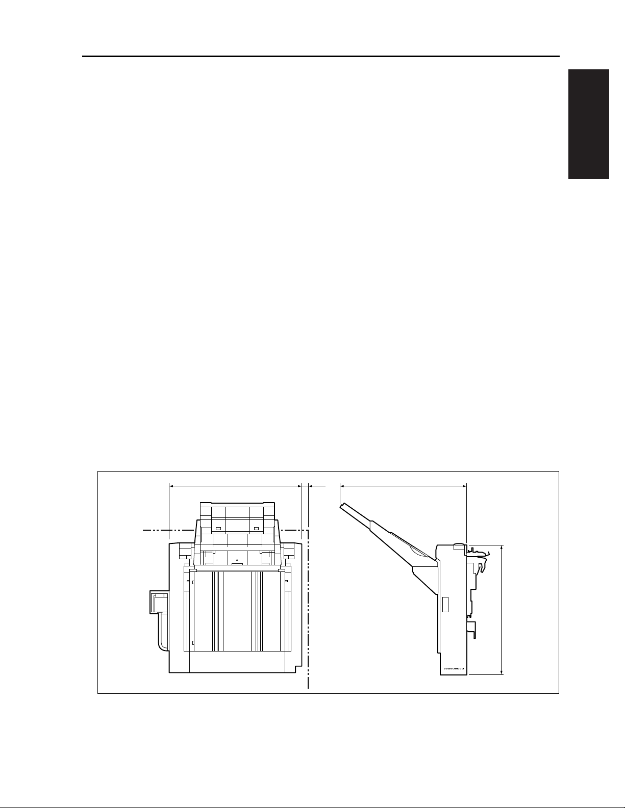
C. Machine Data
Power source: 24VDC (supplied from the main body)
Power consumption: 48VA or less
Weight: 31 lb or less
Machine dimensions:
I OUTLINE
500 483
25
1-1
470
sf1011001
Page 12

SF-101 PRODUCT SPECIFICATIONS
D. Maintenance
Maintenance: Same as the main body.
I OUTLINE
E. Operating Environment
Temperature: 50°F to 90°F
Humidity: 15 to 80%RH
Note:
• The information herein may be subject to change for improvement without notice.
1-2
Page 13

CENTER CROSS-SECTIONAL DRAWING
2. CENTER CROSS-SECTIONAL DRAWING
Shift tray
Exit roller
Reverse roller
I OUTLINE
Conveyance roller
Up/down belt
sf1011002
1-3
Page 14

DRIVE SYSTEM DIAGRAM
3. DRIVE SYSTEM DIAGRAM
3.1 Paper Conveyance Drive
I OUTLINE
3.2 Shift Drive
Exit follower roller
Exit roller
Reverse roller
Timing belt
Conveyance follower
roller
Conveyance roller
M701
(Conveyance motor)
sf1011003
Shift tray plate
Shift tray
Crankshaft
Worm wheel
Timing belt
M703 (Shift motor)
sf1011004
1-4
Page 15

3.3 Tray Drive
DRIVE SYSTEM DIAGRAM
Shift tray
M702 (Tray up/down motor)
I OUTLINE
Up/down belt
sf1011005
1-5
Page 16

PAPER CONVEYANCE PROCESS
4. PAPER CONVEYANCE PROCESS
4.1 Non-Sort Mode
Conveys and ejects the papers ejected from the main body to the shift tray.
I OUTLINE
4.2 Sort/Group Mode
Sets the shift tray to the position it is moved 30mm and conveys and ejects the papers ejected from the
main body.
30mm
Shift tray
sf1011006
1-6
Page 17

2
UNIT EXPLANATION
2 UNIT EXPLANATION
Page 18

2 UNIT EXPLANATION
Blank page
Page 19

II UNIT EXPLANATION
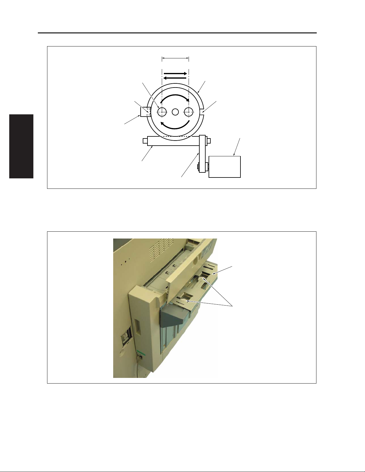
1. EXTERNAL SECTION
1.1 Composition
EXTERNAL SECTION
Cover / R
Shift tray
Conveyance cover
Cover /F
sf1012001
1.2 Mechanism
Mechanism Method
Clearing paper jam *1 Open/Close of conveyance cover
*1 For the paper jammed at the paper conveyance section, hold the knob and open the conveyance cover
to the direction of the arrow to remove the paper.
II UNIT EXPLANATION
Knob
Conveyance cover
sf1012002
2-1
Page 20

PAPER CONVEYANCE SECTION
2. PAPER CONVEYANCE SECTION
2.1 Composition
II UNIT EXPLANATION
SW701
Conveyance follower roller
M701
Exit roller
Reverse roller
Timing belt
Exit follower roller
PS701
2.2 Mechanism
Mechanism Method
Conveyance Belt-driven by conveyance motor
Reverse roller *1 Oscillating system driven by gear /sponge roller
Conveyance roller
sf1012003
*1 Reverse roller, made of sponge, aligns the paper stack in the vertical direction of the ejected papers by
rotating opposite in the direction to the ejection due to the gear drive from the exit roller.
To absorb the up/down movements during the ascent/descent operations of shift tray, up and down
oscillation is allowed mainly for the shaft of exit roller.
Reverse roller
Exit roller
Shift tray (bracket parts)
sf1012004
2-2
Page 21

2.3 Control of M701 (Conveyance Motor)
24V
24V
M701 DRV A
24V
PGND
PGND
FGND
24V IN
GND
GND
M701 DRV A
M701 DRV B
M701 DRV B
PAPER CONVEYANCE SECTION
M701
MTXD
SGND
MCTS
MRXD
SGND
MRTS1
MAIN BODY
RXD
GND
RTS
TXD
GND
CTS
GND
COVER SW
GND
PS701 IN
5V
SFCB
SW701
PS701
sf1012005
M701 (conveyance motor) uses DC stepping motor driven by 24V and is controlled by SFCB (SF control
board).
The related signals are PS701 (conveyance sensor) and SW701 (conveyance cover SW).
2.3.1 Operation
A. Open/Close detection for conveyance cover
The conveyance drive control of SF is started on the start ON signal of the main body, though, when
SW701 (Conveyance cover SW) is OFF, an error information is sent to the main body PRCB and the con-
trol is not started.
B. Control of M701 (conveyance motor)
During the single-sided copy, M701 starts to rotate at low speed on the start ON signal of the main body,
switches itself to high speed on the paper eject ON signal of the main body, and then switches itself to low
speed after a specified time has passed since the paper eject signal of the main body turns OFF.
During the two-sided copy, M701 starts to rotate at low speed on the start ON signal of the main body,
switches itself to medium speed on the paper eject ON signal of the main body, and switches itself to high
speed when the paper eject signal of the main body turns OFF, and then switches itself to low speed after
a specified time.
M701 stops after a specified time has passed since PS701 (conveyance sensor) detected the trailing edge
of final paper.
II UNIT EXPLANATION
2.3.2 Signals
A. SFCB input signals
(1) RXD (MAIN BODY → SFCB)
Serial data line to transmit the operating status of the main body CB to SFCB
(2) CTS (MAIN BODY → SFCB)
Signal permitting transmission from the main body to SF
2-3
Page 22

PAPER CONVEYANCE SECTION
(3) COVER SW (SW701 → SFCB)
(4) PS701 IN (PS701 → SFCB)
B. Output signals
(1) RTS (SFCB → MAIN BODY)
(2) TXD (SFCB → MAIN BODY)
(3) M701 DRV A, A
(4) M701 DRV B, B
II UNIT EXPLANATION
Open/Close detection for conveyance cover
[OPEN]: Conveyance cover is open
[CLOSE]: Conveyance cover is closed
Detection signal of paper passage
[H]: Detects paper
[L]: No paper
Signal permitting transmission from SF to the main body
Serial data line to transmit the operating status of SF to the main body CB
(M701 → SFCB)
Pulse signal for A-phase drive control of M701
(M701 → SFCB)
Pulse signal for B-phase drive control of M701
2-4
Page 23

3. SHIFT SECTION
3.1 Composition
SHIFT SECTION
HP2
Shift tray
Shift table
Shift tray plate
HP1
PS702
Worm gear
3.2 Mechanism
Mechanism Method
Shift *1 Cam-driven by shift motor
Shift table *2 Parallel roller
Crankshaft
Worm wheel
Timing belt
II UNIT EXPLANATION
M703
sf1012006
*1 The crankshaft attached to the worm wheel is driven via the timing belt and worm gear that are
installed to the shaft of M703 (shift motor), and the shift tray moves 30mm back and forth via the shift
tray plate. The worm wheel is integrated with the disk-shaped actuator, which has two home positions
(HP1 and HP2) detected by PS702 (shift HP sensor).
2-5
Page 24
SHIFT SECTION
30mm
II UNIT EXPLANATION
HP1
Shift cam shaft
PS702
Worm gear
Timing belt
HP2
Worm wheel
HP2HP1
M703
sf1012007
*2 Shift tray performs the tray up/down movements in addition to the shift movement by M703 (shift
motor). To facilitate the shift movement without being interfered with by the tray up/down movements,
the shift table, which moves freely to right/left and forward/backward directions, supports the weight of
the tray and the ejected papers. The shift tray is used with parallel rollers.
Shift table
Parallel roller
sf1012008
2-6
Page 25

3.3 Control of M703 (Shift Motor)
SHIFT SECTION
M703 DRV
M703 24V
GND
PS702 IN
5V
MAIN BODY
M703
PS702
sf1012009
During the Sort/Group mode, the offset of papers is performed by M703 (shift motor).
M703 is used with 24V driven DC motor and controlled by SFCB (SF control board).
The related signal is PS702 (shift HP sensor).
3.3.1 Operation
During the Sort/Group mode, M703 (shift motor) is turned ON due to the shift requiring signal from the
main body, makes the tray start performing the shift movement back (HP1) and forth (HP2), and then is
turned OFF due to the HP detection of PS702 (shift HP sensor).
After finishing the exit of final paper, M703 makes a final shift movement to the other HP position (HP1 or
HP2) and prepares itself for the next coping.
3.3.2 Signals
A. SFCB input signal
(1) PS702 IN (PS702 → SFCB)
Shift position detection signal
[H]: Detects HP
[L]: Other than HP
B. Output signal
(1) M703 DRV (SFCB → M702)
Drive control signal for M702
[L]: M702 ON
[H]: M702 OFF
II UNIT EXPLANATION
2-7
Page 26

TRAY SECTION
4. TRAY SECTION
4.1 Composition
II UNIT EXPLANATION
Shift tray
PS703
SW702
Up/down belt
PS704
M702
Up/down pulley /L
sf1012010
4.2 Mechanism
Mechanism Method
Tray up/down *1 Belt-driven by tray up/down motor
Paper detection *2 Photosensor / microswitch
*1 The up/down belt is driven by the worm gear installed to the shaft of M702 (tray up/down motor), which
hoists and lowers the tray. When the up/down pulley /L rotates clockwise viewed from the front, the
shift tray is raised, and when it rotates counterclockwise, it is lowered.
2-8
Page 27

TRAY SECTION
*2 Because of PS703 (tray upper limit sensor), the distance between the exit slot and the top surface of
the paper ejected onto the shift tray is maintained constant to prevent the papers from being ejected
unevenly.
SW702 (tray upper limit SW), of which actuator is integrated mechanically with PS702 actuator, stops
M702 (tray up/down motor) when the shift tray exceeds PS703and rises abnormally. PS704 (tray lower
limit sensor) detects the lowermost limit of the tray.
Shift tray
II UNIT EXPLANATION
PS703
4.3 Control of M702 (Tray Up/Down Motor)
M702 DRV-F
M702 DRV-R
TRAY SW1
TRAY SW2
PS703 IN
PS701 IN
SW702
sf1012011
M702
SW702
GND
PS703
5V
GND
PS704
5V
MAIN BODY
sf1012012
The up/down movements of the tray is performed by rotating M702 (tray up/down motor) normally or
reversely.
M702 is used with 24V driven DC motor and controlled by SFCB (SF control board).
The related signals are PS703 (tray upper limit sensor), PS704 (tray lower limit sensor), and SW 702 (tray
upper limit SW).
2-9
Page 28

TRAY SECTION
4.3.1 Operation
II UNIT EXPLANATION
4.3.2 Signals
A. Other than postcard
Because of the start ON signal of the main body, M702 (tray up/down motor) lowers the tray until PS703
(tray upper limit sensor) turns OFF, and, after a specified time, raises it until PS703 turns ON to stop it.
During copying, M702 is driven after an odd-numbered paper is ejected.
B. Postcard
Because of the start ON signal of the main body, M702 (tray up/down motor) lowers the tray until PS703
(tray upper limit sensor) turns OFF, and, after a specified time, raises it until PS703 turns ON to stop it.
Because of the paper eject signal from the main body for the first paper, M702 lowers the tray and stops it
after it has been driven for a specified time, setting it in its position 50mm down.
During copying, M702 is driven after an odd-numbered paper is ejected.
C. Full-load detection
PS704 (tray lower limit sensor) turns ON and stops M702 (tray up/down motor), producing the message
information to the main body PRCB.
D. Abnormal ascent detection
When SW702 (tray upper limit SW) turns OFF because of the abnormal ascent of the tray, M702 (tray up/
down motor) makes a stop.
A. SFCB input signals
(1) PS703 IN (PS703 → SFCB)
Detection signal of tray upper limit position
[H]: Other than upper limit position
[L]: Upper limit position is detected
(2) PS704 IN (PS704 → SFCB)
Detection signal of tray lower limit position
[H]: Lower limit position is detected
[L]: Other than lower limit position
(3) TRAY SW2 (SW702 → SFCB)
Detection signal of abnormal position exceeding the tray upper limit
[OPEN]: Upper limit abnormality is detected
[CLOSE]: Normal time
B. Output signals
(1) M702 DRV-F (SFCB → M702)
Forward-drive control signal for M702
(2) M702 DRV-R (SFCB → M702)
Reversed-drive control signal for M702
2-10
Page 29

3
DISASSEMBLY/ASSEMBLY
3 DIS./ASSEMBL Y
Page 30

This section explains how to disassemble and reassemble the machine.
When disassembling and reassembling the machine, follow the precautions given below.
3 DIS./ASSEMBL Y
1. Be sure the power cord has been unplugged from the wall outlet.
2. The di sassembled parts must be reassembled fol lowing the di sassembly procedure in reverse unless otherwise specified.
3. Care shoul d be taken not t o lose small parts. Care should also be
taken not to install small parts in wrong places.
4. Do not oper ate the machine before inst alling all the disassembled
parts co mpletely .
5. Removal of some screws is pr ohibited in this section. Never loosen
them.
Page 31

III DISASSEMBLY/ASSEMBLY
1. EXTERNAL
1.1 Removing/Reinstalling the Shift Tray
Caution:
• Make sure power cord of the main unit has
been unplugged from the wall outlet.
A. Procedure
1. Remove the screw [1] and detach the shift tray
[2] to the direction of the arrow so that its claw
[3] is unhooked through the attachment hole [4].
EXTERNAL
[2][1]
[4] [3]
III DIS./ASSEMBLY
sf1013001
3-1
Page 32

EXTERNAL
2. Reinstall the above parts following the removal
steps in reverse.
Caution:
• Make sure that the claw [2] of the shift tray is
inserted into the notch of the shift tray plate
[1] and they are securely engaged.
[2][1]
sf1013002
III DIS./ASSEMBLY
3-2
Page 33

1.2 Removing/Reinstalling the Cover/F
Caution:
• Make sure power cord of the main unit has
been unplugged from the wall outlet.
A. Procedure
1. Open the conveyance cover [1], remove the
screw [2], tilt the upper portion of the cover/F [3]
to the direction of the arrow, and then detach the
cover to the direction of the arrow so that its
claw [4] is unhooked through the attachment
hole [5].
2. Reinstall the above parts following the removal
steps in reverse.
[1]
EXTERNAL
[2]
[3]
III DIS./ASSEMBLY
[5]
[4]
sf1013003
3-3
Page 34

EXTERNAL
1.3 Removing/Reinstalling the Cover/R
Caution:
• Make sure power cord of the main unit has
been unplugged from the wall outlet.
A. Procedure
1. Remove the plastic cover (transparent) [1] and
two screws [2] to detach the connector cover [3].
[1][2]
[3]
III DIS./ASSEMBLY
sf1013004
3-4
Page 35

2. Remove the screw [1] and unhook the claw [2]
to remove the connector cover bracket [3].
EXTERNAL
[1][3]
[2]
III DIS./ASSEMBLY
sf1013005
3-5
Page 36

EXTERNAL
3. Open the conveyance cover [1], remove two
screws [2], tilt the upper portion of the cover/R
[3] to the direction of the arrow, and then detach
the cover to the direction of the arrow so that its
claw [4] is unhooked through the attachment
hole [5].
4. Reinstall the above parts following the removal
steps in reverse.
[1]
[3]
[2]
[5]
III DIS./ASSEMBLY
[4]
sf1013006
3-6
Page 37

2. MAIN BODY
2.1 Removing/Reinstalling the Main Body Unit
Caution:
• Make sure power cord of the main unit has
been unplugged from the wall outlet.
A. Procedure
1. Remove the shift tray.
2. Remove the plastic cover (transparent) [1] and
two screws [2] to detach the connector cover [3].
MAIN BODY
[1][2]
[3]
sf1013007
III DIS./ASSEMBLY
3-7
Page 38

MAIN BODY
3. Remove the screw [1], unhook the claw [2] to
remove the connector cover bracket [3], and
then disconnect the connectors CN200 [4] and
CN201 [5].
[1]
[3][5][2]
III DIS./ASSEMBLY
[4]
sf1013008
3-8
Page 39

4. Remove the screw [1], displace the unit [2]
upward slightly to release the hook [4] from the
hole [3], tilt the upper portion of the unit to the
direction of the arrow, and then detach the unit
[2] by unhooking the claw [6] through the lower
hole [5].
MAIN BODY
[3]
[4]
[2]
[1]
[5]
III DIS./ASSEMBLY
[6]
sf1013009
3-9
Page 40

MAIN BODY
III DIS./ASSEMBLY
Blank page
3-10
 Loading...