

Page 1

SERVICE MANUAL
Models
PZ-108/PZ-109
JANUARY 2004
CSM-PZ108/109
KONICA MINOLTA BUSINESS SOLUTIONS U.S.A., INC.
Page 2

Page 3

PZ-108/PZ-109
SERVICE MANUAL
JANUARY 2004
Used on Konica Models
7075/7085/7155/7165/7255/7272
FORCE 65/FORCE 75/FORCE 85
Page 4

IMPORTANT NOTICE
Because of the possible hazards to an inexperienced
person servicing this equipment, as well as the risk of
damage to the equipment, Konica Minolta Business
Solutions U.S.A., Inc. strongly recommends that all
servicing be performed by Konica-trained service technicians only.
Changes may have been made to this equipment to
improve its performance after this service manual was
printed. Accordingly, Konica Minolta Business Solutions U.S.A., Inc., makes no representations or warranties, either expressed or implied, that the information contained in this service manual is complete or
accurate. It is understood that the user of this manual
must assume all risks or personal injury and/or damage to the equipment while servicing the equipment for
which this service manual is intended.
Corporate Publishing Department
© 2004, KONICA MINOLTA BUSINESS SOLUTIONS U.S.A., INC.
All rights reserved.
Printed in U.S.A.
Page 5

CONTENTS
CONTENTS
SAFETY AND IMPORTANT WARNING ITEMS
Refer to the 7155/7165/7255/7272 Service Manual
1.OUTLINE
PZ-108/PZ-109 PRODUCT SPECIFICATIONS ...... 1-1
[1] Type ............................................................ 1-1
[2] Functions .................................................... 1-1
[3] Applicable Paper ......................................... 1-2
[4] Panch/Z-folding Prohibition Paper .............. 1-2
[5] Particulars of Machine ................................ 1-2
[6] Maintenance and Life.................................. 1-2
[7] Operating Environment ............................... 1-2
CENTER CROSS-SECTIONAL VIEW .................... 1-3
DRIVE SYSTEM DIAGRAM .................................... 1-4
[1] Conveyance Drive Section .......................... 1-4
[2] Punch Section ............................................. 1-5
[3] Punch Scraps Conveyance Section............ 1-6
[4] 1st Folding Stopper Section ........................ 1-7
[5] 2nd Folding Stopper Section ....................... 1-7
PUNCHING PROCESS ........................................... 1-8
[1] Number of punch holes switching
(PZ-109 only) ............................................. 1-9
[2] Switching Mechanism of Gate/L ............... 1-10
[3] Standby Position of Punch Unit ................ 1-11
[4] Formation of a Registration Loop.............. 1-11
[5] Conveyance .............................................. 1-12
[6] Adjustment of Punching Position .............. 1-12
[7] Punch ........................................................ 1-13
Z-FOLDING PROCESS ........................................ 1-14
[1]
Switching Mechanism of Gate/L and Gate/U ...
[2]
Positioning of 1st and 2nd Folding Stoppers ..
[3] 1st Folding ................................................ 1-17
[4] 2nd Folding ............................................... 1-18
1 OUTLINE
2 UNIT EXPLANATION
3 DIS./ASSEMBLY
1-15
1-15
2. UNIT EXPLANATION
EXTERNAL SECTION ............................................ 2-1
[1] Composition ................................................ 2-1
[2] Mechanisms ................................................ 2-1
[3] Interlock Control .......................................... 2-3
CONVEYANCE SECTION ...................................... 2-4
[1] Composition ................................................ 2-4
[2] Mechanisms ................................................ 2-4
[3] Conveyance Control ................................... 2-5
PUNCH SECTION ................................................... 2-7
[1] Composition ................................................ 2-7
[2] Mechanisms ................................................ 2-7
[3] Punch Control ............................................. 2-8
[4] Number of punch holes switching
control (PZ-109 only) .................................. 2-9
PUNCH SCRAPS CONVEYANCE SECTION ....... 2-10
[1] Composition .............................................. 2-10
[2] Mechanisms .............................................. 2-10
[3] Punch Scraps Conveyance Control .......... 2-11
Z-FOLDING SECTION .......................................... 2-12
[1] Composition .............................................. 2-12
[2] Mechanisms .............................................. 2-12
[3] 1st Folding Position Setting Control .......... 2-13
[4] 2nd Folding Position Setting Control ......... 2-13
Page 6

CONTENTS
1 OUTLINE
3. DISASSEMBLY/ASSEMBLY
EXTERNAL SECTION ............................................ 3-1
[1] Removing the PZ (Z-folding and Puncher) .. 3-1
PUNCH SECTION ................................................... 3-2
[1] Replacing the Punch unit ............................ 3-2
[2] Replacing the Punch Clutch (MC1) ............. 3-3
PUNCH SCRAPS CONVEYANCE SECTION ......... 3-5
[1] Replacing the Punch Scraps Conveyance
Motor (M7) .................................................. 3-5
Z-FOLDING SECTION ............................................ 3-6
[1] Removing and Iinstalling the Z-folding/Convey-
ance Unit ..................................................... 3-6
Page 7

SAFETY WARNINGS
[1] Modifications Not Authorized by
Konica Minolta
Konica Minolta equipment is renowned for their high
reliability. This reliability is achieved through high-quality
design and a solid service network.
Unauthorized modifications involve a high risk of degrading performance and safety. Such modifications are therefore strictly prohibited. The points listed below are not
exhaustive, but they illustrate the reasoning behind this
policy.
PROHIBITED ACTIONS :
(1) Using extension cables or a different power cord
than specified by Konica Minolta.
(2) Using other fuses than specified by Konica
Minolta. Safety will not be assured, leading to a
risk of fire and injury.
(3) Disabling fuses or bridging fuse terminals with
wire, metal clips, solder or similar. (This applies
also to thermal fuses.)
(4) Removing air filters (except for replacement).
(5) Disabling relay functions (such as wedging pa-
per between relay contacts, etc.).
(6) Disabling safety functions (interlocks, safety cir-
cuits, etc.). Safety will not be assured, leading to
a risk of fire and injury.
(7) Performing actions to equipment not described
in the instruction manual or the service hand-
book.
(8) Using parts other than specified by Konica
Minolta.
[2] Checkpoints When Performing On-
site Service
Konica Minolta equipment is extensively tested before
shipping, to ensure that all applicable safety standards
are met, in order to protect the customer and customer
engineer from the risk of injury. However, in daily use, any
electrical equipment may be subject to parts wear and
eventual failure. In order to maintain safety and reliability,
the customer engineer must perform regular safety checks.
(3) Be sure to disconnect the power cord of the
equipment from the AC outlet.
Simply turning off the power switch is not sufficient, because paper feed units or other electrical equipment may be powered also when the
power switch is turned off.
(4) Proceed with special care when performing op-
eration checks or adjustment while the unit is
powered. When carrying out operation checks or
adjustment while external covers are removed,
the risk of electrical shock exists when touching
parts which carry high voltage or electrical charge.
The risk of injury exists when touching moving
parts such as gears or chains.
2. Safety Checkpoints
The following list is not exhaustive, but it includes actions
which must be carried out at every on-site service.
CAUTION:
(1) Check external covers and the frame for sharp
edges, burrs, or nicks.
(2) Check external covers and hinges for loosening
or damage.
(3) Check wiring for squeezing or damage.
(4) Check power cord for insulation problems (con-
ductor must not be exposed).
(5) Check power cord and cable ties etc. for loosen-
ing from frame.
WARNING:
(1) Verify that the equipment is properly grounded. If
a problem is detected, establish a proper ground
connection.
(2) Connecting the ground lead to an improper point
such as listed below results in a risk of explosion
and electric shock.
Unsuitable ground points:
- Gas pipe
- Lightning rod
- Telephone line ground
- Plastic water pipe or water pipe or faucet that
has not been approved by authorities for
grounding use
1. Advance Preparation for Safety Checks
CAUTION:
(1) Wear clothing that facilitates work and is de-
signed for safety.
(2) Carry out all procedures carefully to prevent in-
jury.
3. Description of Safety Checks
CAUTION:
(1) Before performing safety check work, read all
relevant documentation (service handbook, technical notices, etc.) and proceed according to the
prescribed procedure, using only the prescribed
tools. Do not carry out any adjustments not
described in the documentation.
Page 8

(2) If the power cord is damaged, replace it only with
the specified power cord. If the power cord insulation has been damaged and there are exposed
sections, short- circuits and overheating may
occur, leading to a serious fire risk.
(3) Do not route the power cord so that it can be
stepped on or pinched. Otherwise overheating
may occur, leading to a serious fire risk.
(4) When disconnecting any cables, always grasp
the connector and not the cable (especially in the
case of AC and high-voltage leads).
(5) Carefully remove all toner remnants from electri-
cal parts, electrodes, etc.
(6) Make sure that wiring cannot come into contact
with sharp edges, burrs, or other pointed parts.
(7) Double-check to make sure that all screws, com-
ponents, wiring, connectors, etc. that were removed for safety check maintenance have been
reinstalled in the original location. (Pay special
attention to forgotten connectors, pinched cables,
forgotten screws, etc.)
(8) When installation and preventive maintenance,
verify that the power cord has been securely
plugged into the AC outlet. Contact problems
may lead to increased resistance, overheating,
and the risk of fire.
WARNING:
Before disassembling or adjusting the equipment, make sure that the power cord has been
disconnected.
[4] Measures to Take in Case of an
Accident
(1) If an accident has occurred, the distributor who has
been notified first must immediately take emergency
measures to provide relief to affected persons and to
prevent further damage.
(2) If a report of a serious accident has been received
from a customer, an on-site evaluation must be
carried out quickly and Konica Minolta must be
notified.
(3) To determine the cause of the accident, conditions
and materials must be recorded through direct onsite checks, in accordance with instructions issued
by Konica Minolta.
(4) For reports and measures concerning accidents,
consult your superior, and follow the regulations set
in "Standards for the Control Program for Measures
Against Electrical Equipment Accidents".
[5] Conclusion
(1) Safety of users and customer engineers depends
highly on accurate maintenance and administration.
Therefore, safety can be maintained by the appropriate by the proper daily service work conducted by the
customer engineer.
(2) When performing service, equipment on the site
must be tested for safety. The customer engineer
must verify the safety of parts and ensure appropriate management of the equipment.
[3]
Handling of Materials for Servicing
CAUTION: Alcohol-based and acetone- based
cleaners are highly flammable and
must be handled with care. When
using these materials for cleaning
parts, observe the following precau-
tions.
(1) Disconnect the power cord from the AC outlet.
(2) Use only a small amount of cleaner at a time and
take care not to spill any liquid. If this happens,
immediately wipe it off.
(3) Perform cleaning only in an environment where
sufficient ventilation is assured. Breathing large
quantities of organic solvents can lead to discomfort.
(4) Do not replace the cover or turn the unit on before
any solvent remnants on the cleaned parts have
fully evaporated.
Page 9

1
OUTLINE
1 OUTLINE
Page 10

1 OUTLINE
Blank page
Page 11
PZ-108/PZ-109 PRODUCT SPECIFICATIONS
PZ-108/PZ-109
[1] Type
Type:
Z-folding and punch machine
[2] Functions
Punching method:
Reciprocating-type punching
Number of holes:
PZ-108
Any of the punch units shown below is
selectively installed corresponding to the
shipping destination. (However, punch units
for other destinations *2 are also available.)
Metric-type 2 holes
Inch-type 2 holes *1
3 holes
4 holes
Swedish-type 4holes
*1 Punch unit for Inch-type 2 holes is not
available in models other than 7075.
*2 Available as spare parts
PZ-109
Any of the punch units shown below is
selectively installed corresponding to the
shipping destination. (However, punch units
for other destinations *2 are also available.)
Metric-type 2 holes and 4 holes (switched
automatically)
Inch-type 2 holes and 3 holes (switched
automatically)
*1 PZ-109 is not available in model 7075.
*2 Available as spare parts
Hole diameter:
6.5 mm (Metric area)
8.0 mm (Inch area)
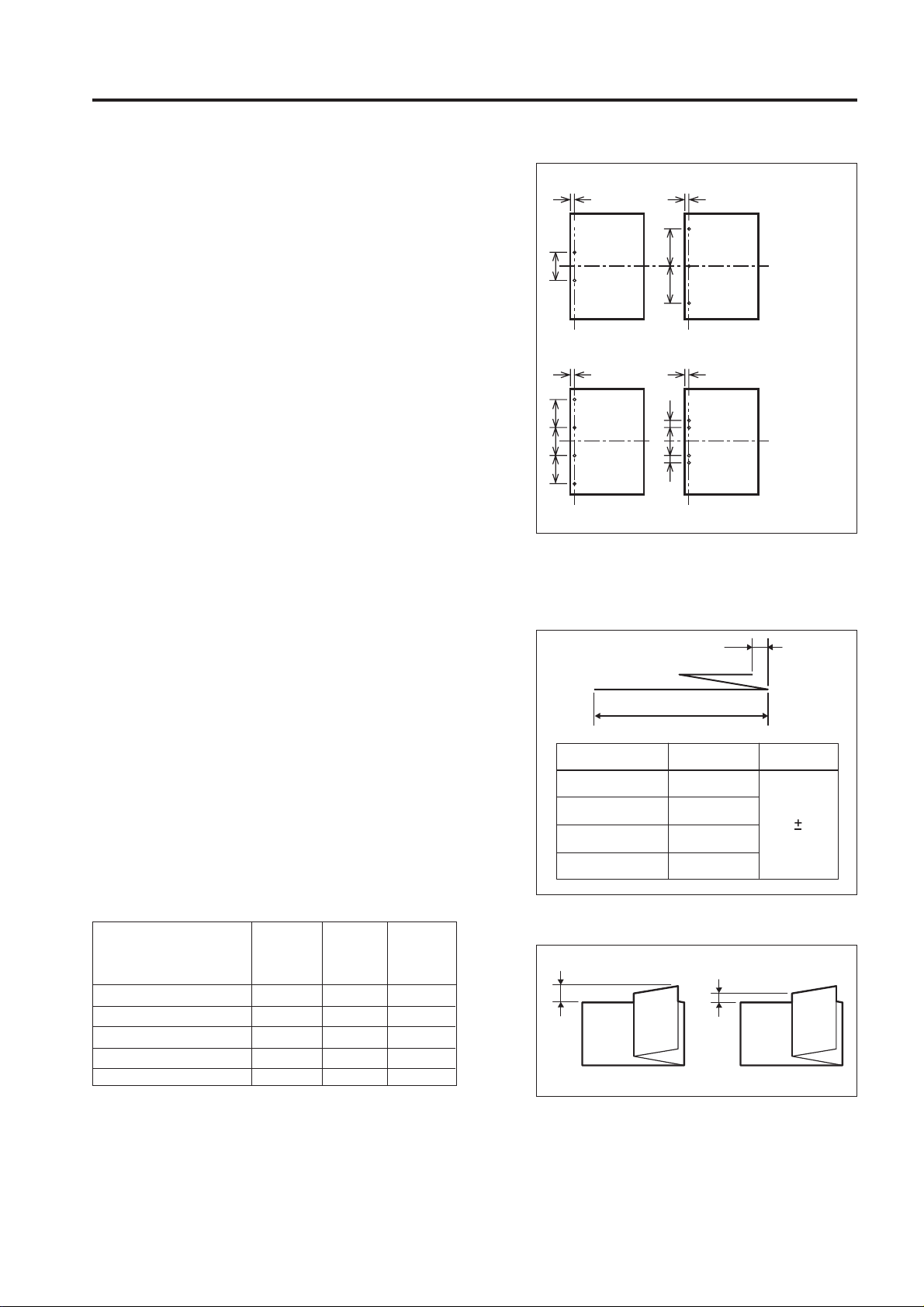
Hole positions and pitches:
Number of holes
Inch-type 2 holes 9.5 70
Metric-type 2 holes 10.5 80
3 holes 9.5 108
4 holes 10.5 80
Swedish-type 4 holes 10.5 70 21
*2 : Range within ± 5mm
A (mm)
Adjustable
*2
B (mm)
Not
adjustable
C (mm)
Not
adjustable
A
B
2 holes
A
B
B
B
4 holes
A
B
B
A
C
B
C
Folding method:
Buckle folding by roller pair
Folding length:
L
Paper size
A3
B4
11 x 17
8.5 x 14
L (mm)
209 or less
181 or less
215 or less
261.6 or less
Folding precision
a: 2mm or less
a
1st folding
1 OUTLINE
Longitudinal
positions
of holes:
Paper center
(adjustable)
3 holes
Longitudinal
positions
of holes:
Paper center
(adjustable)
4 holes (SW)
a
a (mm)
1.53.5
a
2nd folding
1 - 1
Page 12
PZ-108/PZ-109
1 OUTLINE
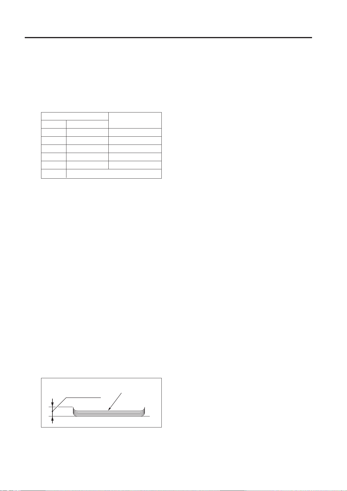
[3] Applicable Paper
Capasity of main tray (21lb.):
The numbers of sheets/sets stackable on the
main tray are shown below.
• Z-folding
30 sheets max.
• Z-folding and stapling
Number of sheets per a set
Folded Non-folded
1 1 to 40 sheet
2 0 to 30 sheet
3 0 to 20 sheet
4 0 to 10 sheet
5 0 Sheet
6 and more
Disable to staple
Maximum number of
sets on main tray (set)
20
10
4
3
2
Non-Punch mode:
Same as main body.
Punch mode:
A3, B4, A4, A4R, B5, B5R, A5, A5R (Metric
area)
11x7, 8.5x14, 8.5x11, 8.5x11R, 5.5x8.5,
5.5x8.5R (Inch area)
High quality paper of 16lb. to 24lb.
This mode cannot be used together with the
folding mode or the stapling and folding
mode.
Z-folding:
A3,B4 (Metric area)
11x17, 8.5x14 (Inch area)
High quality paper of 60g/m2 to 90g/m
The z-folding mode can be used with only
one of the two modes, stapling-andfolding or folding, at the same time.
When B4 paper is used (including mixed
paper loading), the z-folding mode cannot
be used with the staple mode.
Amount of paper curl:
Max. 10 mm
[4] Punch/Z-folding Prohibition Paper
OHP film, Label paper, Blueprint masters,
Holed paper, Tabs
[5] Particulars of Machine
Power source:
100 to 240 VAC (switched automatically)
5VDC (supplied from the main body)
Maximum power consumption:
70 W
Machine dimensions:
6.7(W) x 26(D) x 36.6(H) inch
Weight:
Approximately 84lb.
[6] Maintenance and Life
Maintenance:
Same as the main body
[7] Operating Environment
Temperature:
10 to 30 °C (50 to 86 °F)
Humidity:
10 to 80%RH
Note: The information herein may subject to
change for improvement without notice.
2
Amount of curl
Copied paper (5 sheets)
1 - 2
Page 13
CENTER CROSS-SECTIONAL VIEW
1st folding stopper section
1st folding roller
2nd folding roller
PZ-108/PZ-109
1 OUTLINE
Conveyance roller
2nd folding stopper
section
Exit conveyance roller
Registration section
Gate/U switching section
Conveyance drive roller
Gate/L switching section
Punch section
(Main body)
Punch scraps conveyance section
1 - 3
Punch scraps box
Page 14
PZ-108/PZ-109
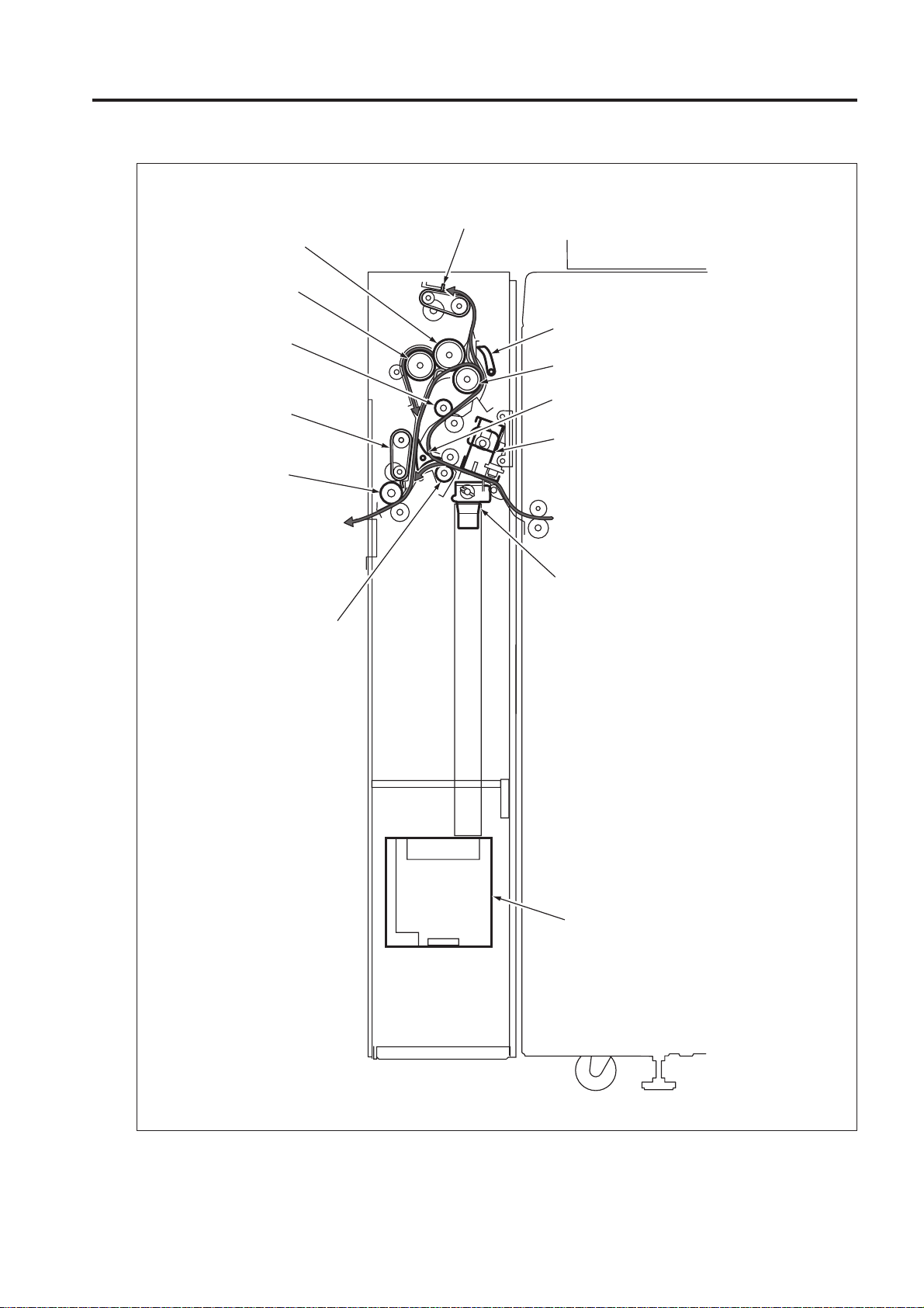
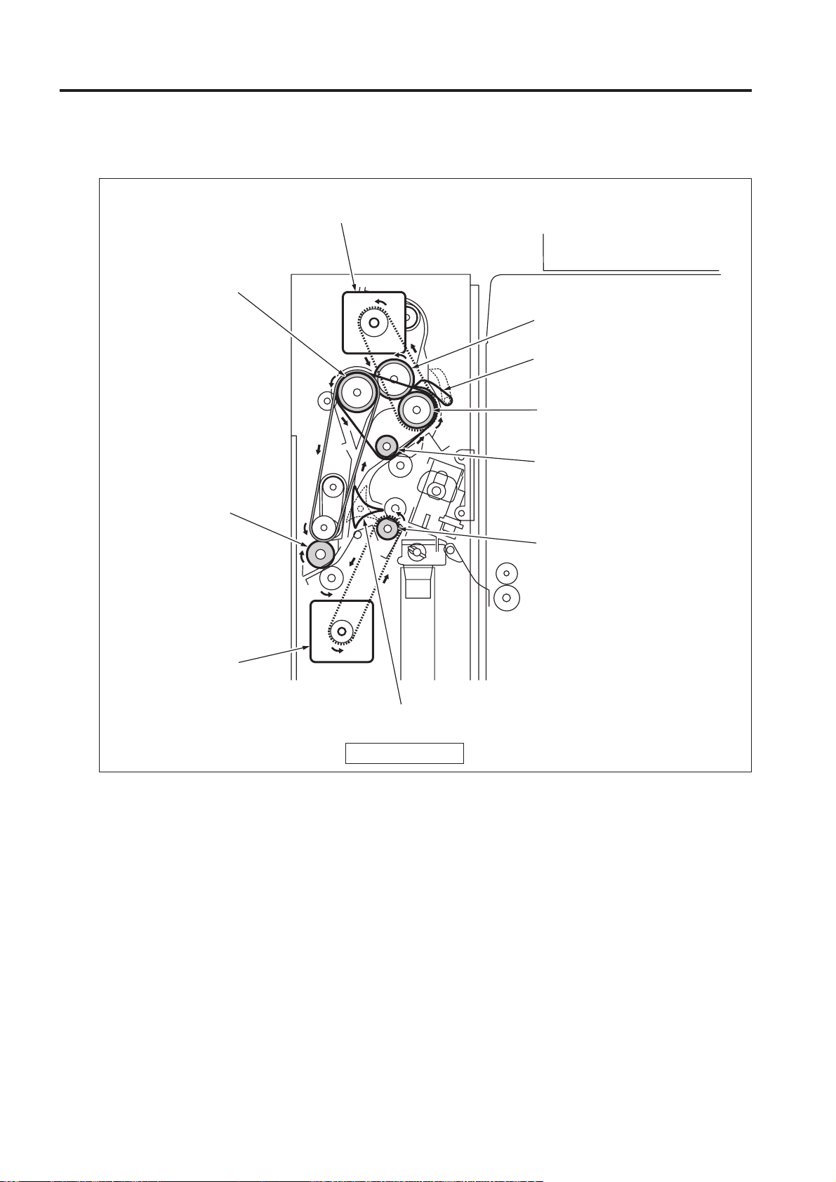
DRIVE SYSTEM DIAGRAM
1 OUTLINE
[1] Conveyance Drive Section
Conveyance motor (M6)
2nd folding roller
1st folding roller
Gate/U (paper path
switching for z-folding)
Conveyance drive roller
Conveyance roller
Exit conveyance roller
Registration motor (M1)
Registration roller
(Main body)
Gate/L (paper path switching)
FRONT VIEW
1 - 4
Page 15
PZ-108/PZ-109
[2] Punch Section
PZ-108
Eccentric cam
FRONT
RIGHT SIDE VIEW
Punch edges
Punch motor (M4)
REAR VIEW
Eccentric cam
Punch clutch (MC1)
1 OUTLINE
Punch clutch
(MC1)
Punch motor (M4)
Rack
Timing belt
Punch shift motor (M5)
PZ-109
Eccentric cam cover
Punch switching motor (M8)
Punch switching cam
Eccentric cam cover
Punch switching
motor (M8)
FRONT
RIGHT SIDE VIEW
Punch motor (M4)
TOP VIEW
Eccentric cam (Inch area: 5 pcs. /
Punch edges
(Inch area: 5 pcs. /
Metric area: 4 pcs.)
REAR VIEW
Metric area: 4 pcs.)
Punch clutch (MC1)
Rack
Timing belt
Punch clutch
(MC1)
Punch motor (M4)
Punch shift motor (M5)
1 - 5
Page 16
PZ-108/PZ-109
1 OUTLINE
[3] Punch Scraps Conveyance Section
Punch scrap conveyance gear
(punch scraps conveyance screw)
Idler gear
Worm gear
Punch scraps conveyance motor (M7)
FRONT VIEW
[4] 1st Folding Stopper Section
Paper stopper
FRONT
1st folding stopper
1st stopper motor (M2)
1 - 6
Page 17
PZ-108/PZ-109
[5] 2nd Folding Stopper Section
2nd folding stopper
1 OUTLINE
FRONT
2nd stopper motor (M3)
Paper
stopper
1 - 7
Page 18

PZ-108/PZ-109
PUNCHING PROCESS
The PZ-108/PZ-109 consists of a punch section, registration section, gate/L switching section, and conveyance
1 OUTLINE
section.
Gate/U switching section
Gate/L switching section
Punch section
Conveyance section
(Main body)
Registration section
Note: The punching process differs be-
tween the punch mode (holes are
made) and the non-punch mode
(no holes are made). Either of
these modes can be selected on
the operation panel of the main
body.When both the punch mode
and the Z folding mode (Z folding is on) are selected, the Z folding process as well as the punch
process will be performed.
Refer to the "Z folding process"
section for more information on
the Z folding action.
The following flowchart shows the flow of
operations performed by the above sections.
These operations are explained hereunder
according to this flowchart.
Punch start
Number of punch holes switching (PZ-109 only)
Gate switching
Movement of punch unit to standby position
Registration loop formation and paper conveyance
1 - 8
Movement of punch unit to the center of paper
Punch
Page 19

PZ-108/PZ-109
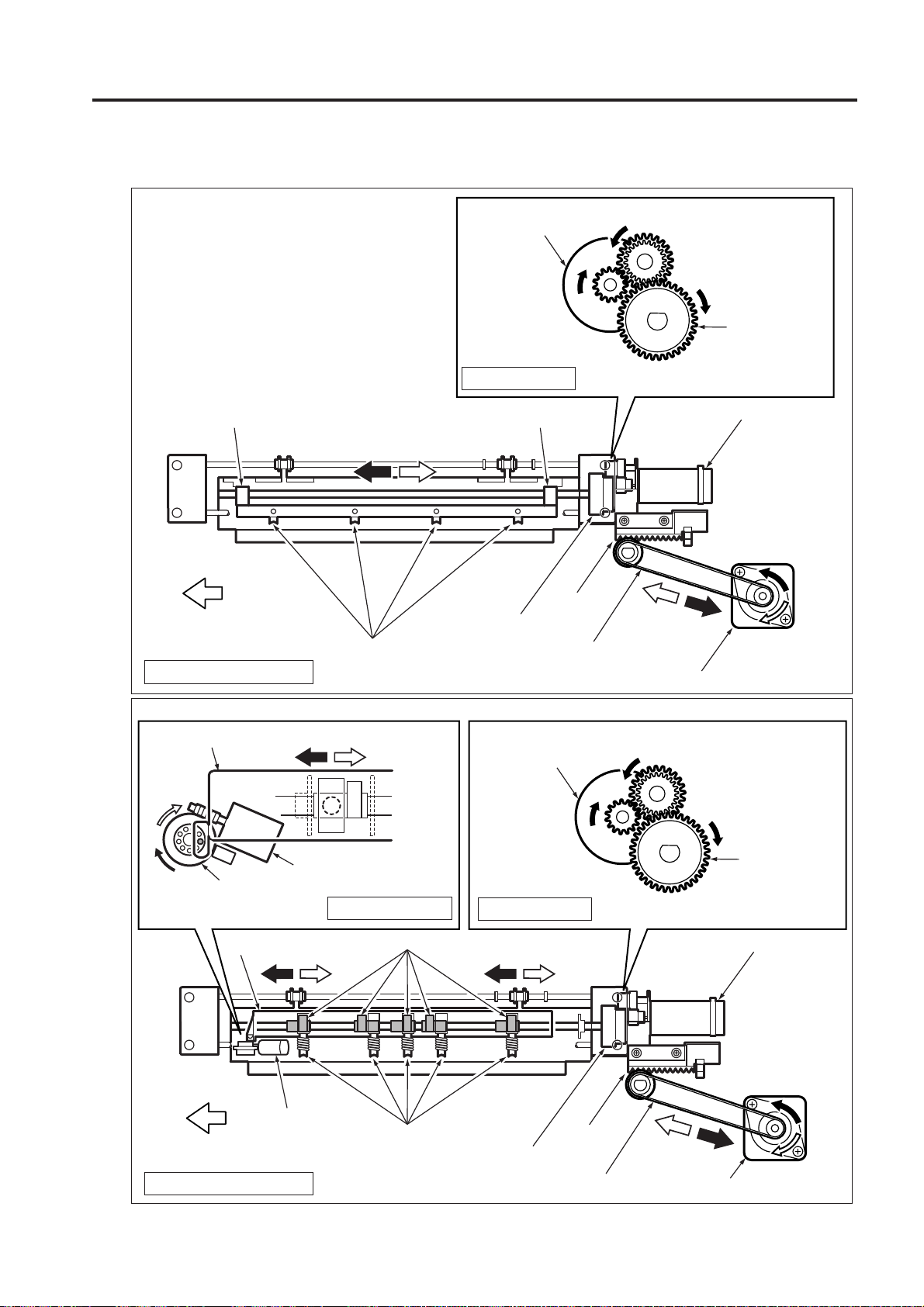
[1] Number of punch holes switching (PZ-109 only)
When the punch mode is active, turning ON START BUTTON of the main body enables the punch switching
motor (M8) to switch the number of punch holes.
When M8 is activated, the punch switching cam is rotated clockwise and the eccentric cams are shifted
forward and backward via the eccentric cam cover. When the eccentric cams are shifted forward, the
eccentric cams for 3 holes (4 holes for Metric area) are set in the eccentric cam bearings, the eccentric cams
for 2 holes come off the bearings. When the eccentric cams are shifted backward, these settings are
switched in reverse way. (For Metric area specification, since 2 holes in central position are also used as
part of 4 holes, the 2 holes are always set in the eccentric cam bearings.)
When the non-punch mode is active and when the number of punches are the same as in previous copying
time, this operation is not performed.
Eccentric cam (for 3 holes)
Eccentric cam cover
Eccentric cam bearing
Eccentric cam (for 2 holes)
1 OUTLINE
Punch
switching
cam
Punch switching cam
Punch switching
motor (M8)
FRONT
Punch switching
position SW (MS2)
Eccentric cam cover
Punch switching motor
(M8)
REAR
* Inch area specification is shown as example in this illustration.
Eccentric cam (for 3 holes /4 holes)
Eccentric cam bearing
Eccentric cam
(for inch area 2 holes)
* Inch area specification is shown as example in this illustration.
1 - 9
Page 20

PZ-108/PZ-109
1 OUTLINE
[2] Switching Mechanism of Gate/L
When the z-folding mode is on, all paper sheets
are conveyed to the upper conveyance path
section.
When the z-folding mode is off, the paper
conveyance path is switched between the upper
conveyance path section or the exit conveyance
roller section, depending on the size of paper and
the current setting of the punching process. This
switching action is performed by the gate/L, which
is driven by the gate SD/L (SD1). In the idling
mode, the gate/L is set toward the exit
conveyance roller (straight exit) section (SD1 is
off).
1. The punch mode is on:
When the punch mode is active, small size paper
sheets are carried to the straight exit section, and
large size paper sheets are carried to the upper
conveyance path section. The large size sheet
that is conveyed to the upper conveyance path
will be controlled by the gate/U, and fed through
the conveyance drive roller and the 1st folding
roller to the exit conveyance rollers.
Gate SD/L ON
(Upper conveyance path)
1st folding roller
Gate/U
Conveyance
drive roller
Gate/L
Exit conveyance
roller
Gate SD/L OFF
(Straight conveyance)
2. The punch mode is off:
When the punch mode is not active, all paper
sheets regardless of their sizes are conveyed to
the exit conveyance rollers.
*1 Refer to the "Z- folding process" section for more
information on the conveyance path and the gate/
U switching mechanism when the z-folding mode
is enabled.
*2 Small sizes
A4, B5, A5, A5R, 8.5 x 11, 5.5 x 8.5, 5.5 x 8.5R
*3 Large sizes
Sizes other than the above
Gate SD/L
Gate/L
Registration
roller
Exit conveyance
roller
FRONT VIEW
1 - 10
Page 21

PZ-108/PZ-109
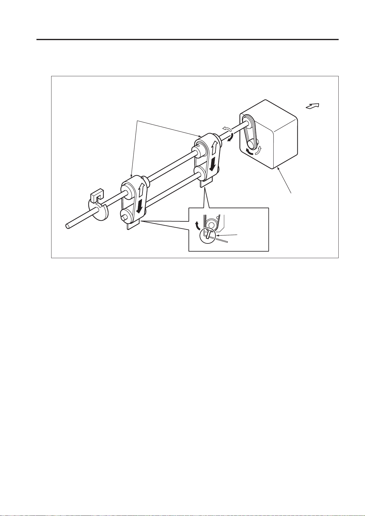
[3] Standby Position of Punch Unit
In the punch mode, the punch unit is moved by
the punch shift motor (M5) so that the paper edge
sensor corresponding to the paper size (the
rightmost sensor for the A4 paper printed in
landscape orientation) is positioned 5 mm inside
the paper edge. When the M5 rotates, its force
is transferred to the rack via the timing belt, thus
moving the punch unit.
In the non-punch mode, the above operation is
not performed.
Punch unit
[4] Formation of a Registration Loop
In the punch mode,the main motor (M1) turns
OFF temporarily to stop conveyance of paper
when the specified time has passed since the
paper edge sensor detected the leading edge of
the paper. Thus, the paper is pressed against
the registration roller forming a loop. When the
specified time passed, the M1 turns ON to restart
conveying the paper.
In the non-punch mode,the above operation is
not performed.
Conveyance motor (M6)
1 OUTLINE
Rack
Timing belt
Punch unit
Punch edge
(Main body)
Loop
Punch shift motor (M5)
Paper edge sensor
5 mm
Registration roller
Registration motor (M1)
Paper conveyance direction
Paper
1 - 11
Page 22

PZ-108/PZ-109
1 OUTLINE
[5] Conveyance
When small-size paper is used in the punch mode
or the non-punch mode is selected, paper is ejected
straight to the FNS via the exit conveyance roller.
When large-size paper is used, the gate is at the
down position and therefore paper is ejected via
the upper conveyance roller and conveyance drive
roller. When the z-folding mode is also selected
by the operation panel of the main body, the gate/
L and gate/U are switched. Thus, paper is carried
to the z-folding section for the z-folding process
via the conveyance roller and conveyance drive
roller irrespective of its size. Refer to “Z-FOLDING
PROCESS” section for more information on the zfolding action.
[6] Adjustment of Punching Position
The punch unit that has been positioned 5 mm
inside the paper edge moves to the center of
paper in the procedure described below.
The punching position is adjusted by moving the
punch unit back and forth during conveyance of
paper.
• The punch unit moves backward until the
specified side edge sensor on paper edge
sensor detects the side edge of paper.
• Next, the punch unit moves forward until the
side edge sensor detects the side edge of
paper again. (Detection of reference position)
• The punch unit moves forward again to position
the punch edges at the center of paper.
Conveyance motor (M6)
Registration motor (M1)
Exit conveyance roller
Gate/U (paper
path switching
for z-folding)
Conveyance
drive roller
Conveyance
roller
Gate/L (paper
path switching)
(Main body)
Punch unit
Punch edge
FRONT
Punch unit movement
direction
* Inch area specification is shown as example in
this illustration. In Metric area specification, 4
holes are provided.
Center of
punch edges
BACK
Paper conveyance
direction
Paper center
Page edge sensor
5 mm
Paper
1 - 12
Page 23

PZ-108/PZ-109
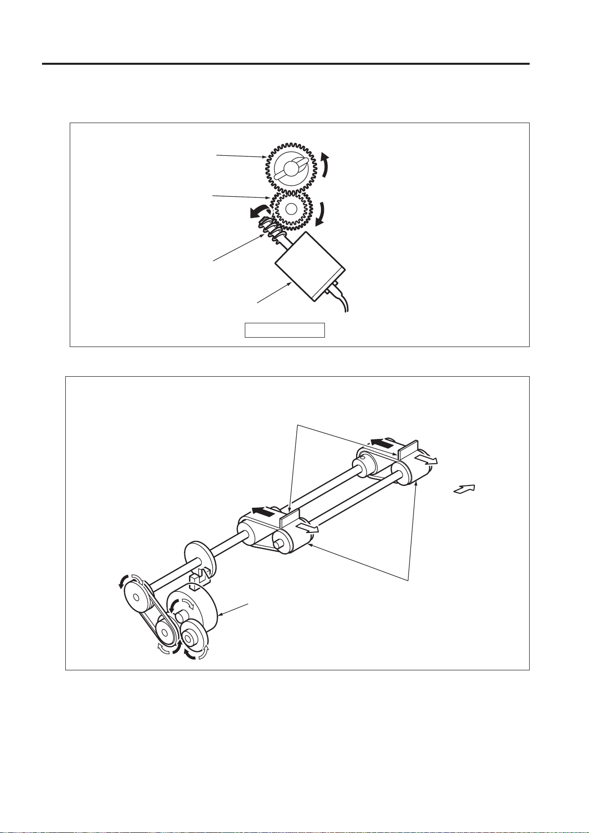
[7] Punch
Holes are punched when the specified time has
passed since the paper edge sensor detected
the trailing edge of the paper. The main motor
(M1) turns OFF to stop paper conveyance
temporarily.
During punching, the punch motor (M4) is rotating
clockwise when viewed from the rear side. When
the punch clutch (MC1) turns ON, the drive force
of the M4 is transferred to the shaft to rotate the
shaft once. As the shaft rotates, the eccentric
cams of the shaft rotate to lower the punch edges,
making holes in the paper. After punching, the
M1 turns ON to eject the paper.
Shaft
Eccentric cam
Punch motor (M4)
1 OUTLINE
Eccentric cam
Punch clutch (MC1)
Top position (HP) Bottom position
Eccentric cam
Paper
* Metric area specification for PZ-108 is shown
as example in this illustration.
Punch edge
FRONT
1 - 13
Page 24

PZ-108/PZ-109
Z-FOLDING PROCESS
The z-folding process of PZ-108 is performed using the gate/L switching, gate/U switching, 1st folding stopper,
1 OUTLINE
folding roller, and 2nd folding stopper sections as shown in the following figure.
1st folding stopper section
Gate/U (paper path switching for z-folding)
Gate/L (paper path switching for z-folding)
Z-folding roller section
2nd folding stopper section
Note: The action of the z-folding process is different depending on whether the current mode is the
z-folding or non z-folding mode. The current mode is selected on the operation panel of the
main body. When both the z-folding and punch (sheets are punched) modes are selected, the
z-folding and punch processes are performed at the same time. Refer to the "PUNCHING
PROCESS" section for more information on the punch action.
(Main body)
1 - 14
Page 25

PZ-108/PZ-109
[1] Switching Mechanisms of Gate/L
and Gate/U
1. The z-folding mode is active:
When the z-folding mode is active, paper sheets
are controlled by the gate/U controls and carried
to the upper conveyance path section regardless
of the sizes. The sheet conveyed to the upper
conveyance path section then will be carried to
the z-folding section by the gate/L. The gate/L
and the gate/U are driven by the gate SD/L (SD1)
and the gate SD/U (SD2) respectively.
2. The non z-folding mode is active:
When the non z-folding mode is active, the paper
(large size paper for the punching process) is
conveyed to the upper conveyance path section.
Then it is controlled by the gate/U, and fed
through the conveyance drive roller and the 1st
folding roller to the exit conveyance rollers.
Gate SD/U ON
(paper path for the z-folding process)
Gate SD/U
Gate/U
Gate SD/U OFF (non z-folding process)
1 OUTLINE
Gate SD/U
Gate/U
FRONT VIEW
1 - 15
Page 26

PZ-108/PZ-109
1 OUTLINE
[2] Positioning of 1st and 2nd Folding Stoppers
Both the 1st and 2nd folding stoppers have its own paper stopper, determining at which position the paper is
folded. The PZ operation start request signal is sent from the main body to rotate the 1st stopper motor (M2)
and the 2nd stopper motor (M3), which returns the 1st and 2nd folding stoppers to their waiting/home
positions (HP). The paper stopper of the 2nd folding stopper is positioned at the bottom to ensure a normal
paper conveyance.
When the paper size signal is received from the main body, the 1st stopper motor (M2) is activated to drive
the 1st folding stopper. This positions the paper stopper of the 1st folding stopper at a point matching the
current paper size. The 1st and 2nd folding stoppers return to their home positions when the FNS operation
end signal is received.
1st folding stopper section
2nd folding stopper section
2nd folding stopper
Paper stoppers
HP position
FRONT
HP position
1st folding stopper
1st stopper motor (M2)
FRONT
1 - 16
2nd stopper motor (M3)
Paper
stopper
HP position
Page 27

PZ-108/PZ-109
[3] 1st Folding
The paper is fed by the registration roller, the conveyance roller, and the conveyance drive roller and carried
to the 1st folding stopper through the gate/U. When the front end of the paper touches the 1st folding
stopper, the upper middle portion of the paper is curled toward the conveyance drive roller and the 1st
folding roller. The front end of the curled paper is pulled into the contact point between these rollers, and the
paper is folded. The folded paper is carried to the 2nd folding stopper section. Because the 1st folding roller
is driven by the conveyance drive roller through the gear, the rotation speed of both rollers is the same.
The 1st folding roller is pressed against the conveyance drive roller and the 2nd folding roller by a spring,
ensuring firm contact conditions between the rollers.
When the punch mode (sheets are punched) is also enabled in the conveyance section of the main body,
the registration motor (M1) and the conveyance motor (M6) temporarily stop upon completion of the 1st
folding process to perform the punch action. Then the M1 and M6 restart to resume the z-folding process.
(Refer to the "Punching process" section for more information on the punch action.)
(Surface)
1st folding stopper
1st folding roller
Loop
1 OUTLINE
2nd folding roller
2nd folding
stopper
Gate/U
Conveyance drive roller
Gate/L
(Main body)
Registration roller
1st folding
(Reverse
side)
2nd folding
1 - 17
Page 28

PZ-108/PZ-109
1 OUTLINE
[4] 2nd Folding
The paper is conveyed to the 2nd folding section and the front edge of it bumps into the 2nd folding stopper,
coming to halt. This makes a loop in the paper in the space between the contact face of the 1st and 2nd
rollers and the contact face of the 1st folding roller and the conveyance drive roller. The front portion of the
loop is pulled into the contact surface between the 1st and 2nd rollers and folded.
During folding operation, when the front edge of the paper have passed through the passage PS (PS1), the
2nd stopper motor (M3) operates to move the 2nd folding stopper to the escape position near the waiting
position (HP). This action makes sure that the paper is fed normally.
1st folding roller
2nd folding roller
Loop
Passage PS
(PS1)
2nd folding
stopper
Conveyance drive roller
(Main body)
(Surface)
1st folding
(Surface)
(Reverse
side)
2nd folding
1 - 18
Page 29

PZ-108/PZ-109
The paper is carried by the 1st and 2nd folding rollers along the route for the 2nd folding process toward the
exit. When the rear end of the paper passes through the exit PS (PS8), the 2nd folding stopper returns to the
position for the current paper size from the escape position to prepare for the next z-folding action.
1st folding roller
2nd folding roller
Conveyance drive roller
2nd folding stopper
Exit PS (PS8)
(Main body)
1 OUTLINE
1 - 19
Page 30

PZ-108/PZ-109
1 OUTLINE
Blank page
1 - 20
Page 31

2
UNIT EXPLANATION
2 UNIT EXPLANATION
Page 32

2 UNIT EXPLANATION
Blank page
Page 33

EXTERNAL SECTION
[1] Composition
PZ-108/PZ-109
Top cover
Front
cover
Front door MS (MS1)
[2] Mechanisms
Z-folding/conveyance unit
2 UNIT EXPLANATION
Punch unit
Rear cover
Mechanism
*1 Jam removal
*1 Jam removal
• To remove the paper jammed at the entrance
of the conveyance section.
Open the front door of the FNS and turn the
jam clear knob.
When removing the paper jammed at the exit
section of the main body, raise the paper
reception guide lever.
• To remove the paper jammed at the exit of
the conveyance section.
Open the front door of the FNS, move the jam
clear lever (1) in the direction of the arrow to
open the conveyance path, and remove the
jammed paper.
Front door (of FNS)
Jam clear knob (1),(2)
Paper reception guide
lever
Jam clear lever (1) to (4)
Method
Jam clear
knob (1)
Jam clear
lever (1)
Paper reception guide lever
2 - 1
Page 34

PZ-108/PZ-109
• Jam removal in the conveyance section
Large size papers in the punch mode,
or papers of any size in the z-folding
mode travel through the upper part in the
conveyance section. When a paper jam
occurs in these circumstances, open the front
door of the FNS and pull the handle to draw
out the z-folding/conveyance unit. Rotate the
jam clear lever (2) in the direction shown by
the arrow in the figure bellow to open the
conveyance path, and remove the jammed
2 UNIT EXPLANATION
paper. Or, pull the jam clear lever (3) in the
direction shown by the arrow in the figure
bellow to open the conveyance path for the
z-folding process, and remove the jammed
paper. Or, with the conveyance path for the
z-folding process kept open, move the jam
clear lever (4) in the direction shown by the
arrow in the figure bellow to open the
conveyance path, and remove the jammed
paper. The jammed paper can be removed by
rotating the jam clear knob (2).
Z-folding/conveyance unit
Handle
Jam clear knob (2)
Jam clear lever (2)
Jam clear
lever (4)
Jam clear lever (3)
Jam clear
knob (2)
Opening the front door of the FNS switches
the front door MS (MS1) off, stopping the AC
power supply to the PZ-108.
2 - 2
Page 35

[3] Interlock Control
PZ-108/PZ-109
AC INPUT
SECTION
PZCB
FRONT DOOR MS
MS1
24V P.G
24V P.G
FG
L
N
DCPS
The interlock control is performed by employing the
interlock switch that detects the FNS front door open
event.
1. Operation
a. Detection of the front door open
The MS1 (front door MS) is an interlock switch.
When the front door of the FNS is opened, the
MS1 switches off, blocking the AC input to the
DCPS (DC power unit). This terminates the 24V
power supply from the DCPS to the PZCB (PZ
control board).
2 UNIT EXPLANATION
2. Signals
a. Input signals
(1) 24V (DCPS to PZCB)
DC24V power input
2 - 3
Page 36

PZ-108/PZ-109
CONVEYANCE SECTION
[1] Composition
Conveyance motor (M6)
Gate SD/U (SD2)
1st folding roller
2 UNIT EXPLANATION
Gate SD/L (SD1)
Exit conveyance roller
Registration motor (M1)
[2] Mechanisms
Mechanism Method
Conveyance drive Registration motor (M1)
Entrance conveyance
Upper conveyance Conveyance roller
Exit conveyance Exit conveyance roller
Gate switching Conveyance path switching by gate solenoid/L (SD1)
Conveyance motor
step out detection
2nd folding roller
Gate/L
Exit PS (PS8)
Conveyance motor (M6)
Registration roller
Conveyance drive roller
1st folding roller (pressed against the conveyance roller and the 2nd folding roller
by means of a spring)
2nd folding roller
Small-size paper in the punch mode and any size paper in the non-punch mode (SD1 OFF):
Large-size paper in the punch mode or paper in the z-folding mode (SD1 ON):
Conveyance path switching by the gate solenoid/U (SD2)
In the non z-folding mode (SD2 OFF): The paper is ejected without the z-folding process.
In the z-folding mode (SD2 ON): The paper is fed through the 1st folding stopper
section and folded to be ejected.
The encoder disk with 40 slits (attached to the shaft of the conveyance motor (M6))
Gate/U
Conveyance drive roller
Conveyance roller
Punch edge
Paper edge sensor
(Main body)
Registration roller
The paper is conveyed under the gate to be ejected.
The paper is conveyed through the upper conveyance path to be ejected.
2 - 4
Page 37

PZ-108/PZ-109
[3] Conveyance Control
5V
PAPER
EDGE
SENSOR
M6
PS9
SD2
MAIN
BODY
PSS-IN1
PSS-IN2
PSS-IN3
PSS-IN4
PSS-IN5
GND
M6 A
M6 A
M6 B
M6 B
M6 24V
M6 24V
5V
M6 EN
GND
SD2-DRV1
SD2-DRV2
M-TXD-OUT
P-REQ-OUT
M-ACK-IN
M-RXD-IN
M-REQ-IN
M-ACK-OUT
PZCB
The paper output from the main body is carried by the
M1 (registration) and the M6 (conveyance). Both the
M1 and M6 are stepping motors, driven by the PZCB
(PZ control board). The M6 is cooled down by the M10
(conveyance motor fan). Related signals are paper
edge sensor, SD1 (gate/L), SD2 (gate/U), PS9
(conveyance encoder), PS1 (passage), and PS8 (exit).
1. Operation
The M1 (registration) and the M6 (conveyance)
are turned ON by the PZ operation request signal, and turned OFF when a predefined time has
elapsed since the paper was ejected.
The PS9 (conveyance encoder) detects the step
out condition of the M6 by monitoring the rotation of the encoder board attached to the shaft of
the M6.
The conveyance section consists of the registration and conveyance sections.
a. Registration section
The M1 is temporarily stopped when a predefined
time has elapsed since the paper edge sensor
detected the leading edge of the paper conveyed
from the main body. A loop is formed in the paper, helping correct paper skew.
The registration control may not be performed in
the non-punch mode.
M1 A
M1 A
M1 B
M1 B
M1 24V
M1 24V
PSS-IN
GND
EXT-PS
GND
SD1-DRV1
SD1-DRV2
M10 24V
M10 DRV
M10-EM
F-TXD-OUT
P-REQ-OUT
F-ACK-IN
F-RXD-IN
F-REQ-IN
P-ACK-OUT
M1
5V
PS1
5V
PS8
SD1
M10
FNS
The M1 is turned ON when a predefined time has
elapsed since the leading edge of the paper reached
the registration roller, resuming the conveyance action.
b. Conveyance section
(1) Punch mode (Large-size paper)
The SD1 (gate/L) is turned ON when the paper
edge sensor detects the leading edge of the
paper, and the paper is ejected through the upper
conveyance path. The PS1 (passage) and the
PS8 (exit) detect whether the paper is of large
size or not. The SD1 is turned OFF when a
predefined time has elapsed since the PS8 detected the paper.
(2) Punch mode (small-size paper) / Non-punch mode
Because the SD1 (gate/L) is in the OFF state, the
paper is ejected without any process.The PS8
(exit) detects the paper ejection.
(3) Z-folding mode
Regardless of paper size, the SD1 (gate/L) and
the SD2 (gate/U) are turned ON when the paper
edge sensor has detected the leading edge of the
paper. After the paper is conveyed through the
upper conveyance path, the 1st folding is performed in the 2nd stopper section, followed by the
2nd folding in the 2nd folding section and the
ejection. The PS1 (passage) and the PS8 (exit)
detect the paper. The SD1 and the SD2 are
turned OFF when a predefined time has elapsed
since the PS8 detected the paper.
2 UNIT EXPLANATION
2 - 5
Page 38

PZ-108/PZ-109
2. Signals
a. Input signals
(1) PS1 PSS-IN (PS1 to PZCB)
Paper conveyance detection signal at the upper
side of paper exit conveyance section.
[L]: Paper exists.
[H]: Paper does not exist.
(2) PS8 EXT-PS (PS8 to PZCB)
Paper conveyance detection signal at the paper
exist conveyance section.
[L]: Paper does not exist.
2 UNIT EXPLANATION
[H]: Paper exists
(3) PS9 M6 EN (PS9 to PZCB)
Step out detection signal of M6 (conveyance).
While the conveyance motor is operating normally, cyclic pulse signals are generated.
(4) Paper edge sensor PSS-IN1 (Paper edge sensor
to PZCB)
The frontmost PS on the paper edge sensor (five
PSs are installed). Detects the leading, rear, and
side edges of the paper.
[L]: Paper does not exist.
[H]: Paper exists.
(5) M10-EM (M10 to PZCB)
Abnornality detection signal of the M10.
The H signal indicates the anomaly.
(6) M-RXD-IN (Main body to PZCB)
Asynchronous serial data from the main body.
(7) M-REQ-IN (Main body to PZCB)
Transmission request signal from the main body
to the PZ.
(8) M-ACK-IN (Main body to PZCB)
Transmission acknowledgement signal from the
main body to the PZ.
(9) F-RXD-IN (FNS to PZCB)
Asynchronous serial data from the FNS.
(10) F-REQ-IN (FNS to PZCB)
Transmission request signal from the FNS to the
PZ.
(11) F-ACK-IN (FNS to PZCB)
Transmission acknowledgement signal from the
FNS to the PZ.
b. Output signals
(1) M1 A, A, B, B (PZCB to M1)
These signals are used to energize the M1 (phases
A and B).
Pulses are controlled to control the conveyance
speed.
(2) M1 A, A, B, B (PZCB to M6)
These signals are used to energize the M6 (phases
A and B).
Pulses are controlled to control the conveyance
speed.
(3) SD1-DRV2 (PZCB to SD1)
ON/OFF signal for the SD1.
[L]: SD1 ON (The magnet is energized)
[H]: SD1 OFF
(4) SD2-DRV2 (PZCB to SD2)
ON/OFF signal for the SD2.
[L]: SD2 ON (The magnet is energized)
[H]: SD2 OFF
(5) M10-DRV (PZCB to M10)
ON/OFF signal for the M10.
[L]: M10 ON
[H]: M10 OFF
(6) M-TXD-OUT (PZCB to Main body)
Asynchronous serial data to the main body.
(7) P-REQ-OUT (PZCB to Main body)
Transmission request signal from the PZ to the
main body.
(8) P-ACK-OUT (PZCB to Main body)
Transmission acknowledgement signal from the
PZ to the main body.
(9) F-TXD-OUT (PZCB to FNS)
Asynchronous serial data to the FNS.
(10) F-REQ-OUT (PZCB to FNS)
Transmission request signal from the PZ to the
FNS.
(11) P-ACK-OUT ((PZCB to FNS)
Transmission acknowledgement signal from the
PZS to the FNS.
2 - 6
Page 39

PUNCH SECTION
[1] Composition
PZ-108
Punch HP PS (PS5)
Eccentric cam
Paper edge sensor
Eccentric cam
Punch shift HP
PS (PS4)
PZ-108/PZ-109
Punch motor (M4)
2 UNIT EXPLANATION
FRONT
PZ-109
Eccentric cam
Punch switching
cam
Punch switching
position SW (MS2)
FRONT
Punch edges
RIGHT SIDE VIEW
Eccentric cam
(Inch area: 5pcs. /
Metric area: 4pcs.)
Punch edges(Inch area: 5pcs. /
Metric area: 4pcs.)
Punch switching motor
(M8)
RIGHT SIDE VIEW
Punch clutch(MC1)
Punch HP PS (PS5)
Paper edge sensor
Punch clutch(MC1)
Rack
Timing belt
Punch shift motor (M5)
Punch shift HP PS (PS4)
Punch motor (M4)
Rack
Timing belt
Punch shift motor (M5)
[2] Mechanisms
Mechanism Method
Back-and-forth Punch shift motor (M5)
movement of punch unit Rack
Reciprocating movement Punch motor (M4)
of punch Punch clutch (MC1)
Number of punch holes
switching
(PZ-109 only)
Eccentric cam (2 pcs.)
Punch edges
Punch switching motor (M8)
Punch switching position SW (MS2)
Punch switching cam
Eccentric cam cover
2 - 7
Page 40

PZ-108/PZ-109
[3] Punch Control
PAPER
EDGE
SENSOR
2 UNIT EXPLANATION
MAIN
BODY
5V
PSS-IN1
PSS-IN2
PSS-IN3
PSS-IN4
PSS-IN5
GND
PZCB
M-TXD-OUT
P-REQ-OUT
M-ACK-IN
M-RXD-IN
M-REQ-IN
M-ACK-OUT
M5 A
M5 A
M5 B
M5 B
M5 24V
M5 24V
M4-DRV
M4-24V
MC1-DRV
MC1-24V
P-HP1-IN
GND
P-HP2-IN
GND
F-TXD-OUT
P-REQ-OUT
F-ACK-IN
F-RXD-IN
F-REQ-IN
P-ACK-OUT
5V
5V
The back-and-forth movement of the punch unit is
driven by the M5 (punch shift). The M4 (punch) and
MC1 (punch clutch) are used for punch operation. M4
is DC motor and rotationg during punching. Related
signals are PS4 (punch shift HP) and PS5 (punch HP).
1. Operation
Punch operations are classified into two types:
back-and-forth movement of the punch unit and
hole punching. In the punch mode, punch operations are performed for each sheet of paper.
In the non-punch mode, punch operations are
not performed.
a. Back-and-forth movement of punch unit
Punch positioning operation
The M5 is turned ON when the specific time has
passed since the paper edge sensor detect the
leading edge of the paper, and turned OFF after
finished the punch positioning operation.
Paper edge sensor is used for punch positioning. This sensor includes the five PSs as follows.
The leftmost sensor is a leading/trailing/side edge
sensor. The remaining four sensors are side
edge sensors used to detect side edges of paper.
The side edge sensor to be used is determined
by the size of the paper used.
M5
M4
MC1
PS4
PS5
FNS
Paper edge sensor
(1) (2) (3) (4) (5)
Leading/trailing/
side edge sensor
Side edge sensors
b. Hole punching
The M4 is turned ON by PZ operation signal from
the main body. The MC1 turns ON when the
specified time has passed since the paper edge
sensor detected the training edge of the paper,
the hole punching operation is performed.
The PS5 detect the punch edge HP.
2. Signals
a. Input signals
(1) Paper edge sensor PSS-IN1 to IN5 (Paper edge
sensor to PZCB)
• PSS-IN1 (Leading/trailing/side edge sensor)
• PSS-IN4 to IN5 (Side edge sensors)
[L]: Paper does not exist.
[H]: Paper exists.
(2) PS4 P-HP1-IN (PS4 to PZCB)
Punch unit HP detection signal.
[L]: Other than HP
[H]: HP
(3) PS5 P-HP2-IN (PS5 to PZCB)
Punch HP detection signal.
[L]: Other than HP
[H]: HP
2 - 8
Page 41

PZ-108/PZ-109
b. Output signals
(1) M4 DRV (PZCB to M4)
M4 ON/OFF signal.
[L]: M4 ON
[H]: M4 OFF
(2) M5 A, A, B, B (PZCB to M5)
These signals are used to energize the M5 (phases
A and B).
Pulses are controlled to control the rotation speed
and the direction of rotation.
(3) MC1 DRV (PZCB to MC1)
MC1 drive signal (pulse signal).
[L]: MC1 ON
[H]: MC1 OFF
[4] Number of punch holes
switching control (PZ-109 only)
M8 DRV
M8 24V
MS2 CONT
GND
MAIN
BODY
M-TXD-OUT
P-REQ-OUT
M-ACK-IN
M-RXD-IN
M-REQ-IN
M-ACK-OUT
F-TXD-OUT
P-REQ-OUT
F-ACK-IN
F-RXD-IN
F-REQ-IN
P-ACK-OUT
The number of punch holes switching is performed by
M8 (Punch switching motor).
The related signal is MS2 (Punch switching position
SW).
1. Operation
M8 (Punch switching motor) is turned ON when
the number of holes contained as data in PZ
operation request signal sent from the main body
is different from actual number of holes presently
set. When the 3 punch holes positioning (4 punch
holes positioning for Metric area specification) is
selected by switching, MS2 (Punch switching
position SW) is switched from ON to OFF after a
specified time has passed. When the 2 punch
holes positioning is selected by switching, MS2
is switched from OFF to ON after a specified time
has passed.
M8
MS2
FNS
2 UNIT EXPLANATION
2. Signals
a. Input signals
(1) MS2 CONT (MS2 to PZCB)
Punch switching position detecting signal
[L]: 3 holes (4 holes for Metric area specification)
[H]: 2 holes
b. Output signals
(1) M8 DRV (PZCB to M8)
M8 ON/OFF signal
[L]: M8 ON
[H]: M8 OFF
2 - 9
Page 42

PZ-108/PZ-109
PUNCH SCRAPS CONVEYANCE SECTION
[1] Composition
2 UNIT EXPLANATION
Punch scraps collection duct
[2] Mechanisms
Mechanism Method
*1 Alarm clear Punch scraps box
Punch scraps conveyance drive Punch scraps conveyance motor (M7)
Punch scraps conveyance Punch scraps conveyance screw
Punch scraps box
Punch scraps conveyance
motor (M7)
Punch scraps conveyance screw
Punch scraps collection duct
*1 Alarm clear
Punch scraps are collected in the punch scraps
box.
When the punch scraps box is full or it is removed,
the related message appears on the operation
panel of the main body.
To remove the punch scraps box, open the front
door of the FNS and pull forward.
Punch scraps full
sensor (PS7)
Punch
scraps box
Punch scraps box
detect sensor (PS6)
2 - 10
Page 43

PZ-108/PZ-109
[3] Punch Scraps Conveyance Control
5V
BOX-IN
GND
P-FULL-IN
PZCB
M7-24V
M7-DRV
MAIN
BODY
M-TXD-OUT
P-REQ-OUT
M-ACK-IN
M-RXD-IN
M-REQ-IN
M-ACK-OUT
Punch scraps are conveyed by the driving forth of the
M7 (punch scraps conveyance). Conveyed punch
scraps are collected in the punch scraps box through
the punch scraps collection duct. Related signals are
PS6 (punch scraps box) and PS7 (punch scraps full).
PS6
PS7
M7
2. Signals
a. Input signals
(1) PS6 BOX-IN (PS6 to PZCB to Main body)
Punch scraps box existence detection signal.
[L]: Punch scraps box does not exists.
[H]: Punch scraps box exist.
(2) PS7 P-FULL-IN (PS7 to PZCB to Main body)
Punch scraps box full detection signal.
[L]: Punch scraps box is full.
[H]: Punch scraps box is not full.
b. Output signal
(1) M7 DRV (PZCB to M7)
M7 ON/OFF control signal.
[L]: M7 ON
[H]: M7 OFF
2 UNIT EXPLANATION
1. Operation
a. Punch scraps full detection
The PS7 (punch scraps full) detects whether the
punch scraps box is full. When the punch scraps
box becomes full, the PS7 turns ON to send the
"punch scraps full" signal to the main body. Upon
receipt of this signal, the main body displays a
related message on the operation panel.
b. Punch scraps box detection
The PS6 (punch scraps box) detects whether the
punch scraps box is attached. If the punch scraps
box is not attached, the PS6 turns ON to send
the "punch scraps box not attached" signal to
the main body. Upon receipt of this signal, the
main body displays a related message on the
operation panel.
c. Punch scraps conveyance
The M7 (punch scraps conveyance) is a DC motor and driving the punch scraps conveyance
screw. It turns ON when the specified time has
passed since the paper edge sensor detected
the training edge of the paper.
Punch scraps are fed forward by the punch
scraps conveyance screw and collected into the
punch scraps box through the punch scraps collection duct.
2 - 11
Page 44

PZ-108/PZ-109
Z-FOLDING SECTION
[1] Composition
1st folding section
2 UNIT EXPLANATION
2nd folding section
2nd folding stopper
Paper stopper
1st stopper HP (PS3)
1st stopper motor (M2)
FRONT
1st folding stopper
FRONT
2nd stopper HP (PS2)
[2] Mechanisms
Mechanism Method
1st folding position setting 1st stopper motor (M2)
1st folding stopper
2nd folding position setting 2nd stopper motor (M3)
2nd folding stopper
2 - 12
2nd stopper motor (M3)
Paper
stopper
Page 45

PZ-108/PZ-109
[3] 1st Folding Position Setting Control
M2 A
M2 A
M2 B
M2 B
M2 24V
M2 24V
5V
S-HP1-IN
GND
MAIN
BODY
M-TXD-OUT
P-REQ-OUT
M-ACK-IN
M-RXD-IN
M-REQ-IN
M-ACK-OUT
PZCB
F-TXD-OUT
P-REQ-OUT
F-ACK-IN
F-RXD-IN
F-REQ-IN
P-ACK-OUT
The M2 (1st stopper) sets the position of the paper for
the 1st folding. Related signal is PS3 (1st stopper HP).
1. Operation
a. 1st folding position setting
The position of the paper stopper on the 1st folding stopper sets the paper position for 1st folding.
The M2 (1st stopper) is activated by the PZ operation request signal to start searching for its
HP. When the PS3 (1st stopper HP) detects the
HP, the M2 stops. Then, upon receipt of the paper size signal from the main body, the M2 drives
the 1st folding stopper to the position where the
1st folding is performed for the paper of the specified size.
When the PZ operation end signal is received
from main body, the M2 starts searching for its
HP to return the 1st folding stopper there.
2. Signals
a. Input signals
(1) PS3 S-HP1-IN (PS3 to PZCB)
1st folding stopper HP detection signal
[L]: HP
[H]: Other then HP
b. Output signals
(1) M2 A, A, B, B (PZCB to M2)
M2 A, A, B, B (PZCB to M2)
These signals are used to energize the M2 (phases
A and B).
Pulses are controlled to control the rotation speed
and the direction of rotation.
M2
PS3
FNS
[4] 2nd Folding Position Setting Control
M3 A
M3 A
M3 B
M3 B
M3 24V
M3 24V
S-HP2-IN
5V
PSS-IN
GND
EXT-PS
PZCB
F-TXD-OUT
P-REQ-OUT
F-ACK-IN
F-RXD-IN
F-REQ-IN
P-ACK-OUT
MAIN
BODY
M-TXD-OUT
P-REQ-OUT
M-ACK-IN
M-RXD-IN
M-REQ-IN
M-ACK-OUT
The M3 (2nd stopper) sets the position of the paper
for the 2nd folding. Related signals are PS2 (2nd
stopper HP), PS1 (passage), and PS8 (exit).
1. Operation
a. 2nd folding position setting
The position of the paper stopper on the 2nd folding stopper sets the paper position for 2nd folding.
The M3 (2nd stopper) is activated by the PZ operation request signal to start searching for its
HP. When the PS2 (2nd stopper HP) detects the
HP, the M3 stops. Then, upon receipt of the paper size signal from the main body, the M3 drives
the 2nd folding stopper to the position where the
2nd folding is performed for the paper of the
specified size.
After the completion of the 2nd folding, the paper is carried forward. When the PS1 (passage)
detects the rear edge of the paper, the M3
counterrotates to drive the 2nd folding stopper in
the inverse direction, which makes the paper
stopper move to the escape position. With the
paper stopper at this position, the paper is fed
normally.
When the PS8 (exit) detects the end of the paper, the M3 is activated to move the paper stopper to the original position for the next z-folding
action.
When the PZ operation end signal is received
from main body, the M2 starts searching for its
HP again to return the 2nd stopper there.
M3
PS2
PS1
PS8
FNS
2 UNIT EXPLANATION
2 - 13
Page 46

PZ-108/PZ-109
2. Signals
a. Input signals
(1) PS2 S-HP2-IN (PS2 to PZCB)
2nd stopper HP detection signal
[L]: HP
[H]: Other then HP
b. Output signals
(1) M3 A, A, B, B (PZCB to M3)
These signals are used to energize the M3 (phases
A and B).
2 UNIT EXPLANATION
Pulses are controlled to control the rotation speed
and the direction of rotation.
2 - 14
Page 47

3
DISASSEMBLY/ASSEMBLY
3 DIS./ASSEMBLY
Page 48

3 DIS./ASSEMBLY
This section explains how to disassemble and reassemble the machine.
When disassembling and reassembling the machine, follow the precautions given below.
1. Be sure the power cord has been unplugged from the wall outlet.
2. The disassembled parts must be reassembled following the disassembly procedure in reverse unless otherwise specified.
3. Care should be taken not to lose small parts. Care should also be
taken not to install small parts in wrong places.
4. Do not operate the machine before installing all the disassembled
parts completely.
5. Removal of some screws is prohibited in this section. Never loosen
them.
Page 49

EXTERNAL SECTION
PZ-108/PZ-109
[1]
Removing the PZ (Z-folding and Puncher)
Caution: Be sure to unplug the power
cords of the main body and this
machine from the wall outlet.
a. Procedure
(1) Loosen the two screws in the lower part of the
rear cover of the PZ, then remove the two screws
in the upper part to remove the rear cover.
(2) Open the front door of the FNS and raise the
paper reception guide lever of the PZ to retract
the paper reception guide in the PZ.
(3) Remove the three screws securing the PZ to the
main body, draw out the PZ, and remove the two
relay connectors (CN95 and CN96) of the PZ
from the main body.
Relay connectors (CN96)
Relay connectors (CN95)
3 DIS./ASSEMBLY
Screws
Screws (loosen)
Paper reception guide lever
(4) Remove the two screws (front side) fixing the PZ
and the FNS, and remove two screws (rear side)
fixing the positioning plate.
(5) Pull the lever of the FNS installation stay to
release the fixing the PZ and the FNS, and detach
the PZ by lifting.
(6) Remove the two relay connectors of the FNS
from the PZ.
(7) Reinstall the above parts following the removal
steps in reverse.
Rear cover
3 - 1
Page 50

PZ-108/PZ-109
PUNCH SECTION
[1] Replacing the Punch unit
Caution: Be sure to unplug the power
cords of the main body and this
machine from the wall outlet.
Caution: The following screws should not be
removed. If you do, punching cannot
be done as designed.
PZ-108
Screws that should not
be removed
3 DIS./ASSEMBLY
PZ-109
Screws that should not be removed
Punch unit
Retaining ring
that should not
be removed
Screws that should not
be removed
Screws that should not be removed
Retaining ring
that should not
be removed
Screws that should not be removed
3 - 2
Page 51

PZ-108/PZ-109
a. Procedure
(1) Remove the sensor mounting stay by removing a
screw.
[2] Replacing the Punch Clutch (MC1)
Caution: Be sure to unplug the power
cords of the main body and this
machine from the wall outlet.
Caution: The punch unit gear rotates only in the
direction of the arrow.
Never turn it in the direction opposite
to the arrow direction. If you do so,
the MC1 (punch clutch) will break.
Caution:Never turn the gear in the
direction opposite to the
arrow direction.
3 DIS./ASSEMBLY
Sensor mounting stay
Screw
(2) Cut the wiring harness band and disconnect the
relay connector (1 pc. (2 pcs. for PZ-109)) upward.
(3) Remove the punch unit by removing four screws.
Punch unit
Wiring harness band
O K
N G
Screws
Relay connector
a. Procedure
(1) Remove the punch unit. See "[1] Replacing the
Punch unit."
(2) Remove the punch motor unit by removing two
screws.
(3) Cut the three wiring harness bands and discon-
nect the punch clutch relay connector (CN52).
Wiring harness bands
Relay connector
(CN52)
(4) Reinstall the above parts following the removal
steps in reverse.
Caution: When reinstalling, harnes the band in
same direction. (see the figure is step
(3))
3 - 3
Screw
Punch motor unit
Screw
Page 52

PZ-108/PZ-109
(4) Remove the punch clutch by removing the retain-
ing ring.
Stopper
Punch clutch
Retaining ring
(5) Reinstall the above parts following the removal
3 DIS./ASSEMBLY
steps in reverse.
Caution 1: Fasten all the three wiring harness
bands with the tightening part
oriented as shown in the illustration.
See the figure in step (3).
Caution 2: When installing the punch motor
unit, push the punch motor gear
against the punch clutch gear.
After installing the punch motor
unit, check for backlash.
Caution 3: When installing the punch clutch,
take care of the position of the
stopper.
3 - 4
Page 53

PUNCH SCRAPS CONVEYANCE SECTION
PZ-108/PZ-109
[1] Replacing the Punch Scraps
Conveyance Motor (M7)
Caution: Be sure to unplug the power
cords of the main body and this
machine from the wall outlet.
a. Procedure
(1) Disconnect the relay connector (CN47)
(2) Remove the punch scraps conveyance motor
unit by removing the two screw.
(3) Remove the punch scraps conveyance motor
from the bracket by removing the two screws.
Screws
Punch scraps conveyance motor
(4) Apply grease (Plus guard No.2) to the worm gear
of the new punch scraps conveyance worm gear.
(5) Reinstall the above parts following the removal
steps in reverse.
Caution: When installing the M7 (with a
bracket), provide backlash.
Installing the M7 too closely to the right
end will reduce backlash to zero.
3 DIS./ASSEMBLY
Punch scraps
conveyance motor unit
Screws
Relay connector (CN47)
3 - 5
Page 54

PZ-108/PZ-109
Z-FOLDING SECTION
[1]
Removing and Installing the Z-folding/
Conveyance Unit
Caution: Be sure to unplug the power
Caution 1: Take care of the z-folding/
Caution 2: The following screws should not be
3 DIS./ASSEMBLY
cords of the main body and this
machine from the wall outlet.
conveyance unit dropping since it
is heavy.
or removed. If you do z-folding
cannot be done as designed.
(3) Pull out the z-folding/conveyance unit.
(4) Disconnect three connectors (CN30, CN32,
CN36) at the arm joint section.
(5) Remove two screws to remove the arm.
Caution: The arm should be held by the hand
when removal, since it falls.
Z-folding/conveyance unit
Screw
Connector
(CN32)
Connector
(CN30)
Screw that should
not be removed
a. Procedure
(1) Remove the PZ from the main body and FNS.
(2) Remove four screws to remove the top cover.
Screw
Screw that should
not be removed
Top cover
Screw
Connector
(CN36)
Arm
(6) Return the z-folding/conveyance unit to the ba-
sis.
3 - 6
Page 55

(7) Remove two screws to remove the FNS jointing
plate.
(8) Remove four screws to remove the z-folding/
conveyance unit with the rails pulling out to the
front.
PZ-108/PZ-109
Screws
Screws
Rail
holder
Rail holder
FNS jointing plate
Rail holder
Screws
Rail holder
(9) Install the above parts following the removal
steps in reverse.
Caution: Put the z-folding/conveyance unit on
four rail holders certainly when
installing. (For fall prevention)
3 DIS./ASSEMBLY
3 - 7
Page 56

PZ-108/PZ-109
3 DIS./ASSEMBLY
Blank page
3 - 8
 Loading...