

Page 1

INSTALLATION MANUAL
FS-501
Finisher
for Product Code 4036
NOTES
• Before installing, be sure to unplug the power cord of the machine.
• Keep all packing materials out of the reach of children.
4684-7761-01 Printed in Japan
Page 2
FS-501
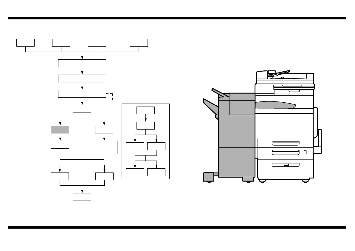
■ Outline of Installation Procedures for 4036 System
PC-101 PC-201 DK-501
Dehumidifier Heater 1C
Copier/Printer Machine
Electron System Options
FS-501
JS-601
DF-601
PC-401
✱ Electron System Options
AD-501
FS-601
PK-501/PK-4/
PK131
OC-501
WT-501
EM-301
HD-501
EK-501 VI-501
D-103DT-105
When installing the machine and associated options as a system, follow the order shown
on the left.
NOTE
For the detailed installation procedures for each option, follow the instructions given
in the corresponding Installation Manual and perform the procedures correctly.
4684U057AB
– 1 –
Page 3
FS-501
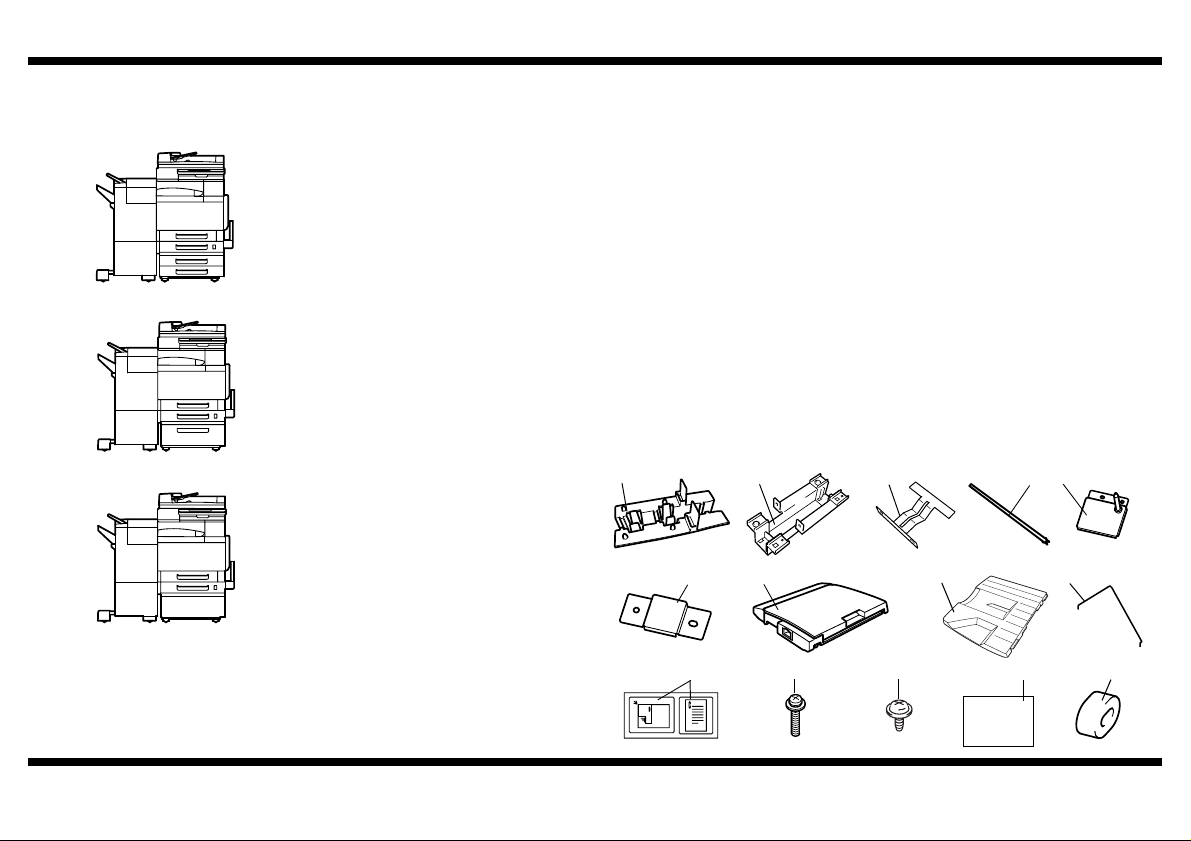
■ Before Installing the Finisher
In order to adjust the height of the machine to the height of the finisher, the Paper Feed
Cabinet PC-101, or PC-201, or PC-401, or Desk must be installed.
<Machine + Paper Feed Cabinet PC-101/PC201>
4684U058AA
<Machine + Paper Feed Cabinet PC-401>
4684U059AA
<Machine + Desk>
4684U060AA
■ Unpacking the Finisher
1. Check that the following accessories are available in the box.
1 Rail guide A............................................................................................1
2 Rail guide B............................................................................................1
3 Ground plate ..........................................................................................1
4 Rail .........................................................................................................1
5 Stabilizing pin .........................................................................................1
6 Magnet plate ..........................................................................................1
7 Horizontal transport unit .........................................................................1
8 Tray ........................................................................................................1
9 Protective guide .....................................................................................1
10 Label ......................................................................................................1
11 Screws A................................................................................................3
12 Screws B ................................................................................................2
13 Installation manual (this manual) ...........................................................1
14 Spacer ....................................................................................................1
* Rail Guide A is not used when the FS-501 is mounted on the machine (product code
4036).
1 4 5
4698U044AA 4698U045AB 4698U046AB
6 7 8
4698U047AA 4698U048AA 4684U075AA
10 11
2 3
4684U061AB 4684U062AA
9
4684U070AA
12
13
14
– 2 –
4684U072AA4684U076AA
9735U001AA
4583U018AA
Page 4

2. Remove all tape and packing brackets.
Ta pe
FS-501
Packing
bracket
NOTES
• Make sure that the installation site is flat and level.
• After the Finisher has been set up, avoid moving it unless it is absolutely neces-
sary.
When the Finisher needs to be moved, perform the steps by referring to “Removing
the Rail” on p. 7.
After the Finisher has been moved, perform the steps given in “Installing the Horizontal Transport Unit” on p. 5 and step 5, 6 on p. 4.
C4683U006AB
C4683U008AA
4643U003AA
4684U074AA
NOTE
Do not remove these parts.
Packing bracket
C4683U005AA
– 3 –
Page 5

FS-501
■ Installing the Accessories
4583U016AA
C4683U009AA
4684U063AB
4684U064AA
1. Peel off the seal covering the area where the
stabilizing pin and magnet plate will be
attached.
2. Attach the enclosed stabilizing pin and
magnet plate with the enclosed screws A to
the left side of the machine as shown.
3. Place the Ground Plate furnished with the kit
in Rail Guide B.
4. Attach the rail guide B to the left side of the
Paper Feed Unit as shown in the illustration
(two screws B furnished with the finisher).
NOTE
Fit Rail Guide B in the tab on the lower
portion of the Paper Feed Unit.
4684U065AA
4583U017AB
C4683U010AA
C4683U011AA
5. Insert the rail into the Rail Guide B.
6. Protrude the leading edge of the rail out
about 60 mm to the right from the right end of
the machine.
NOTE
If the rail is pulled out more than necessary,
it is caught by the flat spring fitted to the
machine as it is brought back into the
original position.
7. Insert the spacer that comes with the finisher
into the rail.
NOTE
Slide out the rail to the left and check that it
does not come off the Rail Guide B.
8. Slide the other end of the rail installed in step
5 into the rail guide on the finisher.
NOTE
Insert the rail until it snaps into place.
At this time, the finisher should stay
attached to the machine, even if you try to
pull it away.
– 4 –
Page 6

FS-501
■ Unpacking the Horizontal Transport Unit
Remove all packing materials and tape.
Ta pe
C4651U023AB
■ Installing the Horizontal Transport Unit
1. Place the horizontal transport unit on the
paper output section of the machine, and
make sure that the plastic guide pin on the
bottom of the horizontal transport unit hooks
into the bracket on the finisher.
C4683U023AA
2. Push the horizontal transport unit in.
NOTE
Make sure that the gears on the horizontal
transport unit and on the finisher are
correctly aligned.
C4683U014AA
3. Secure the horizontal transport unit with the
lock.
NOTE
Firmly secure the Horizontal Transport Unit
and the Finisher in position using the Lock
Lever.
■ Adjusting the Height and Tilt of the Finisher
1. If the finisher gradually tilts toward the
machine, check the following:
• Are the stabilizing pin and the hole in the finisher at the same height?
• Is the horizontal transport unit not extremely
tilted?
4684U066AA
4643U021AB
4643U020AA
* If the finisher is not at the same height as the
machine, adjust the machine as follows.
2. Slide the finisher away from the machine,
and then remove the lower-front cover (two
screws) of the finisher.
3. Lift the finisher’s two caster covers up, and
then pull them off.
C4683U013AA
– 5 –
Page 7

FS-501
Adjusting
bolt
4643U022AB
4684U067AA
Securing bolt
a
b
Securing bolt
Adjusting bolt
4. Without turning the adjusting bolt (lower bolt)
on the caster, loosen the securing bolt (upper
bolt), and then turn the adjusting bolt (lower
bolt) as indicated below to adjust the height
of the finisher.
<Two rear casters>
If the stabilizing pin is too high:
Turn the bolt clockwise
If the stabilizing pin is too low:
Turn the bolt counterclockwise
<Two front casters>
If the magnet plate is too high:
Turn the bolt clockwise
If the magnet plate is too low:
Turn the bolt counterclockwise
5. If the finisher tilts toward the machine, check
the following:
• Are distances a and b equal?
* If a and b are not equal, refer to step 4 above
and turn the adjusting bolt (lower bolt) as
indicated to adjust the tilt of the finisher.
6. After the adjustment is finished, without
turning any of the adjusting bolts (lower
bolts), tighten the four securing bolts (upper
bolts).
■ Connecting the Hookup Cord
1. Remove the connector covers from the
horizontal transport unit and the machine.
2. Connect the hookup cord to the horizontal
transport unit and the machine.
4684U068AA
3. Secure the hookup cord of the Horizontal
Transport Unit using the cord clamp (large) of
the finisher.
4684U069AA
4643U029AA
7. Re-install the caster covers and the lowerfront cover (two screws).
– 6 –
Page 8

FS-501
■ Installing the Tray and Protective Guide
Install the enclosed tray and protective guide at
the positions shown in the illustrations.
4643U024AA
4643U017AA
■ Removing the Rail
1. Pinch together the rail stoppers on the left
side of the finisher to release them.
2. Disconnect the two hookup cords.
3. Remove the horizontal transport unit from the
finisher, and then place it on top of the
C4651U020AA
machine.
4. Carefully pull the finisher away from the
machine.
■ Affixing the Labels
Affixing the enclosed operation labels.
Label for Machine Label for RADF
C4683U018BA
for Machine
for RADF
4684U076AA
4698U109AA
5. Slide the rail under the machine, and then
remove it from the right side of the machine.
– 7 –
 Loading...