

KONICA MINOLTA EP6000 Service Manual

EP6000
GENERAL,
MECHANICAL/
ELECTRICAL

CONTENTS
GENERAL
1. SAFETY INFORMATION . . . . . . . . . . . . . . . . . . . . . . . . . . . . . . . . G-1
2. TECHNICAL HIGHLIGHTS. . . . . . . . . . . . . . . . . . . . . . . . . . . . . . . G-2
3. SPECIFICA TIONS. . . . . . . . . . . . . . . . . . . . . . . . . . . . . . . . . . . . . . G-3
4. SPACE REQUIREMENTS . . . . . . . . . . . . . . . . . . . . . . . . . . . . . . . G-7
5. PRECAUTIONS FOR INSTALLATION . . . . . . . . . . . . . . . . . . . . . G-8
6. PRECAUTIONS FOR USE . . . . . . . . . . . . . . . . . . . . . . . . . . . . . . . G-9
7. HANDLING OF THE CONSUMABLES . . . . . . . . . . . . . . . . . . . . . G-10
8. SYSTEM OPTIONS. . . . . . . . . . . . . . . . . . . . . . . . . . . . . . . . . . . . . G-11
9. PARTS IDENTIFICATION. . . . . . . . . . . . . . . . . . . . . . . . . . . . . . . . G-12
MECHANICAL/ELECTRICAL
1. CROSS-SECTIONAL VIEW . . . . . . . . . . . . . . . . . . . . . . . . . . . . . . M-1
2. COPY PROCESS . . . . . . . . . . . . . . . . . . . . . . . . . . . . . . . . . . . . . . M-3
3. DRIVE SYSTEM . . . . . . . . . . . . . . . . . . . . . . . . . . . . . . . . . . . . . . . M-5
4. SEQUENTIAL EXPLANATION. . . . . . . . . . . . . . . . . . . . . . . . . . . . M-7
5. WATCHDOG (CPU OVERRU N MONITOR) FUNCT ION . . . . . . . M-11
6. MALFUNCTION BYPA SS FUNCT ION. . . . . . . . . . . . . . . . . . . . . . M-14
7. IMAGE STABILIZATION SYSTEM. . . . . . . . . . . . . . . . . . . . . . . . . M-16
8. PC DRUM. . . . . . . . . . . . . . . . . . . . . . . . . . . . . . . . . . . . . . . . . . . . . M-25
8-1. PC Drum . . . . . . . . . . . . . . . . . . . . . . . . . . . . . . . . . . . . . . . . . . M-25
8-2. PC Drum Drive Mechanism/Control . . . . . . . . . . . . . . . . . . . . M-25
8-3. Grounding of the PC Drum . . . . . . . . . . . . . . . . . . . . . . . . . . . M-27
8-4. Drum Dry Heater . . . . . . . . . . . . . . . . . . . . . . . . . . . . . . . . . . . M-27
9. DRUM CHARGING . . . . . . . . . . . . . . . . . . . . . . . . . . . . . . . . . . . . . M-28
9-1. PC Drum Charge Corona . . . . . . . . . . . . . . . . . . . . . . . . . . . . M-28
9-2. Control of the PC Drum Char ge Corona . . . . . . . . . . . . . . . . M- 30
9-3. PC Drum Charge Corona Wires Cleaning
Mechanism/Control . . . . . . . . . . . . . . . . . . . . . . . . . . . . . . . . . M-31
9-4. Ozone Filter . . . . . . . . . . . . . . . . . . . . . . . . . . . . . . . . . . . . . . . M-33
i

CONTENTS
10. OPTICAL SECTION. . . . . . . . . . . . . . . . . . . . . . . . . . . . . . . . . . . . . M-3 4
10-1. Construction . . . . . . . . . . . . . . . . . . . . . . . . . . . . . . . . . . . . . . M-34
10-2. Function of Exposure Components . . . . . . . . . . . . . . . . . . . M-36
10-3. Exposure Lamp LA1 Control. . . . . . . . . . . . . . . . . . . . . . . . . M-37
10-4. Intensity Correction . . . . . . . . . . . . . . . . . . . . . . . . . . . . . . . . M-42
10-5. Scanner and Mirrors Carr iage Moving Mechanism. . . . . . . M-43
10-6. Scanner Motor M11 Control . . . . . . . . . . . . . . . . . . . . . . . . . M-45
10-7. Lens Drive Mechanism/Control. . . . . . . . . . . . . . . . . . . . . . . M-47
10-8. Optical Section Cooling Fan Motor . . . . . . . . . . . . . . . . . . . . M-53
11. ORIGINAL SIZE DETECTING SYSTEM. . . . . . . . . . . . . . . . . . . . M-54
11-1. Construction . . . . . . . . . . . . . . . . . . . . . . . . . . . . . . . . . . . . . . M-54
11-2. Construction of the Original Size Detecting Sensor . . . . . . M-55
11-3. Original Detection Method. . . . . . . . . . . . . . . . . . . . . . . . . . . M-56
11-4. Sensor Locations . . . . . . . . . . . . . . . . . . . . . . . . . . . . . . . . . . M-58
11-5. Original Size Detection . . . . . . . . . . . . . . . . . . . . . . . . . . . . . M-5 9
11-6. Original Size Detection Processing . . . . . . . . . . . . . . . . . . . M-60
12. IMAGE ERASE LAMP . . . . . . . . . . . . . . . . . . . . . . . . . . . . . . . . . . . M-62
12-1. Image Erase Lamp LA3. . . . . . . . . . . . . . . . . . . . . . . . . . . . . M-62
12-2. Image Erase Lamp LA3 ON/OFF Control . . . . . . . . . . . . . . M-63
12-3. Control for Each Erase Function. . . . . . . . . . . . . . . . . . . . . . M-64
13. DEVELOPING UNIT . . . . . . . . . . . . . . . . . . . . . . . . . . . . . . . . . . . . M-69
13-1. Construction . . . . . . . . . . . . . . . . . . . . . . . . . . . . . . . . . . . . . . M-69
13-2. Developing Unit Drive Mechanism . . . . . . . . . . . . . . . . . . . . M-70
13-3. Developer Flow . . . . . . . . . . . . . . . . . . . . . . . . . . . . . . . . . . . M-71
13-4. Magnetic Pole Positioning. . . . . . . . . . . . . . . . . . . . . . . . . . . M-73
13-5. ATDC Sensor . . . . . . . . . . . . . . . . . . . . . . . . . . . . . . . . . . . . . M-75
13-6. Control for Abnormally Low T/C . . . . . . . . . . . . . . . . . . . . . . M-78
13-7. Sub Hopper Toner Replenishing Mechanism/Control. . . . . M-80
13-8. Sub Hopper Toner Empty Detecting Mechanism/Contro l. . M-82
13-9. Main Hopper Toner Replenishing Mechanism/Control . . . . M-85
13-10. Auxiliary Toner Replenishing . . . . . . . . . . . . . . . . . . . . . . . M-88
13-11. Developing Bias. . . . . . . . . . . . . . . . . . . . . . . . . . . . . . . . . . M-90
13-12. Developing Unit Dehumidifying Heater . . . . . . . . . . . . . . . M-91
13-13. Toner Suction Fan Motor. . . . . . . . . . . . . . . . . . . . . . . . . . . M-92
14. PRE-IMAGE TRANSFER ERASE LAMP. . . . . . . . . . . . . . . . . . . . M-93
14-1. Pre-Image Transfer Erase Lamp . . . . . . . . . . . . . . . . . . . . . M-93
14-2. Pre-Image Transfer Erase Lamp LA4 ON/OFF Control . . . M-93
ii

CONTENTS
15. PAPER TAKE-UP/F EED SECTION . . . . . . . . . . . . . . . . . . . . . . . . M-95
15-1. Construction . . . . . . . . . . . . . . . . . . . . . . . . . . . . . . . . . . . . . . M-95
15-2. Drawer-in-Position Detection . . . . . . . . . . . . . . . . . . . . . . . . M-96
15-3. Paper Empty Detection . . . . . . . . . . . . . . . . . . . . . . . . . . . . . M-97
15-4. Paper Lifting/Lowering Mechanism/Control. . . . . . . . . . . . . M-99
15-5. Paper Stack Lowering/Drawer Locking Mechanism/
Control (Inch Areas). . . . . . . . . . . . . . . . . . . . . . . . . . . . . . . . M-103
15-6. Paper Level Detection . . . . . . . . . . . . . . . . . . . . . . . . . . . . . . M-105
15-7. 3rd-Drawer-in-Position Detection . . . . . . . . . . . . . . . . . . . . . M-107
15-8. 3rd Drawer Paper Empty Detection . . . . . . . . . . . . . . . . . . . M-1 08
15-9. Main Tray Paper Stack Lifting/Lowering Mechanism/
Control . . . . . . . . . . . . . . . . . . . . . . . . . . . . . . . . . . . . . . . . . . M-110
15-10. 3rd D r awer Pap er Level Detect ing Mechanism . . . . . . . . . M-114
15-11. Shifter Drive Mechanism/Control . . . . . . . . . . . . . . . . . . . . M-115
15-12. 3rd Drawer Lock/Release . . . . . . . . . . . . . . . . . . . . . . . . . . M-1 18
15-13. Paper Dehumidifying Heaters. . . . . . . . . . . . . . . . . . . . . . . M-119
15-14. Drawer Paper Take-Up Mechanism/Control . . . . . . . . . . . M-120
15-15. Vertical Transport Drive Mechanism . . . . . . . . . . . . . . . . . M-126
15-16. Multi Bypass Table. . . . . . . . . . . . . . . . . . . . . . . . . . . . . . . . M-128
16. TRANSPORT/SYNCHRONIZING ROLLERS UNIT . . . . . . . . . . . M-136
16-1. Construction . . . . . . . . . . . . . . . . . . . . . . . . . . . . . . . . . . . . . . M-136
16-2. Paper Dust Remover . . . . . . . . . . . . . . . . . . . . . . . . . . . . . . . M-1 37
16-3. Transport Roller Drive Mechanism. . . . . . . . . . . . . . . . . . . . M-137
16-4. Transport Roller Drive Control . . . . . . . . . . . . . . . . . . . . . . . M-1 38
16-5. Synchronizing Roller Drive Mechanism . . . . . . . . . . . . . . . . M-139
16-6. Synchronizing Roller Drive Control. . . . . . . . . . . . . . . . . . . . M-140
16-7. Prevention of Low Image Density on Copy . . . . . . . . . . . . . M-142
17. IMAGE TRANSFE R/ PAP ER SEPARATOR CORONAS. . . . . . . . M-143
17-1. Image Transfer/Paper Separator Coronas. . . . . . . . . . . . . . M-143
17-2. Image Transfer/Paper Separator Coronas Control . . . . . . . M-144
17-3. Image Transfer/Paper Separator Corona Wires Cleaning
Mechanism/Control . . . . . . . . . . . . . . . . . . . . . . . . . . . . . . . . M-145
17-4. Image Transfer/Paper Separator Coronas Assy Retracting
Mechanism . . . . . . . . . . . . . . . . . . . . . . . . . . . . . . . . . . . . . . . M-148
17-5. Ozone Filter . . . . . . . . . . . . . . . . . . . . . . . . . . . . . . . . . . . . . . M-149
18. CLEANING UNIT. . . . . . . . . . . . . . . . . . . . . . . . . . . . . . . . . . . . . . . M-150
18-1. Construction of the Cleaning Unit. . . . . . . . . . . . . . . . . . . . . M-150
18-2. Cleaning Blade Moving Mechanism. . . . . . . . . . . . . . . . . . . M-151
iii

CONTENTS
18-3. Toner Conveying/Collecting Mechanism . . . . . . . . . . . . . . . M-152
18-4. Pre-Cleaning Erase Lamp LA5 ON/OFF Control. . . . . . . . . M-154
18-5. PC Drum Paper Se parator Fingers M oving Mechanism/
Control . . . . . . . . . . . . . . . . . . . . . . . . . . . . . . . . . . . . . . . . . . M-155
18-6. Cleaning Bias (Option) . . . . . . . . . . . . . . . . . . . . . . . . . . . . . M-159
19. MAIN ERASE LAMP . . . . . . . . . . . . . . . . . . . . . . . . . . . . . . . . . . . . M-160
19-1. Main Erase Lamp. . . . . . . . . . . . . . . . . . . . . . . . . . . . . . . . . . M-160
19-2. Main Erase Lamp LA2 ON/OFF Control. . . . . . . . . . . . . . . . M-160
20. TRANSPORT SECTION . . . . . . . . . . . . . . . . . . . . . . . . . . . . . . . . . M-162
20-1. Transport Section. . . . . . . . . . . . . . . . . . . . . . . . . . . . . . . . . . M-162
20-2. Suction Fan Motor M18 Control . . . . . . . . . . . . . . . . . . . . . . M-163
21. FUSING UNIT . . . . . . . . . . . . . . . . . . . . . . . . . . . . . . . . . . . . . . . . . M-164
21-1. Construction . . . . . . . . . . . . . . . . . . . . . . . . . . . . . . . . . . . . . . M-164
21-2. Fusing Rollers and Web Roller. . . . . . . . . . . . . . . . . . . . . . . M-166
21-3. Drive for the Fusing Unit . . . . . . . . . . . . . . . . . . . . . . . . . . . . M-167
21-4. Fusing Rollers Pressure Mechanism . . . . . . . . . . . . . . . . . . M-169
21-5. Oil Application Mechanism . . . . . . . . . . . . . . . . . . . . . . . . . . M-1 69
21-6. Cleaning Web Take-Up Mechanism/Control . . . . . . . . . . . . M-170
21-7. Fusing Temperature Control . . . . . . . . . . . . . . . . . . . . . . . . . M-172
21-8. CPM Control . . . . . . . . . . . . . . . . . . . . . . . . . . . . . . . . . . . . . M-176
22. EXIT/DUPLEX SWITCHING UNIT . . . . . . . . . . . . . . . . . . . . . . . . . M-178
22-1. Construction . . . . . . . . . . . . . . . . . . . . . . . . . . . . . . . . . . . . . . M-178
22-2. Exit/Duplex Switching Mechanism/Control . . . . . . . . . . . . . M-179
23. DUPLEX UNIT TURNOVER MECHANISM . . . . . . . . . . . . . . . . . . M-181
23-1. Construction . . . . . . . . . . . . . . . . . . . . . . . . . . . . . . . . . . . . . . M-181
23-2. Drive Mechanism . . . . . . . . . . . . . . . . . . . . . . . . . . . . . . . . . . M-182
23-3. Duplex Unit Turnover Mechanism . . . . . . . . . . . . . . . . . . . . M-183
24. DUPLEX UNIT . . . . . . . . . . . . . . . . . . . . . . . . . . . . . . . . . . . . . . . . . M-186
24-1. Construction . . . . . . . . . . . . . . . . . . . . . . . . . . . . . . . . . . . . . . M-186
24-2. Trailing Gate Unit Moving Mechanism/Control . . . . . . . . . . M-188
24-3. Gate Switching Mechanism/Control . . . . . . . . . . . . . . . . . . . M-189
24-4. Trailing Gate Unit Moving and Gate Switching
Operations . . . . . . . . . . . . . . . . . . . . . . . . . . . . . . . . . . . . . . . M-190
24-5. Front/Rear Edge Guide Plate Drive Mechanism/
Control . . . . . . . . . . . . . . . . . . . . . . . . . . . . . . . . . . . . . . . . . . M-191
24-6. Storing of Copies in Duplex Unit. . . . . . . . . . . . . . . . . . . . . . M-193
iv

CONTENTS
24-7. Leading Edge Guide Plate and Duplex Paper Take-Up
Drive Mechanism/Control . . . . . . . . . . . . . . . . . . . . . . . . . . . M-195
24-8. Duplex Paper Take-Up Operation . . . . . . . . . . . . . . . . . . . . M-197
25. POWER SUPPLY . . . . . . . . . . . . . . . . . . . . . . . . . . . . . . . . . . . . . . M-201
26. MEMORY BACKUP. . . . . . . . . . . . . . . . . . . . . . . . . . . . . . . . . . . . . M-204
v

SAFETY INFORMATION
1
(ALL Areas)
Danger of explosion if battery is incorrectly replaced.
(Denmark only)
Lithi umb at teri - Eksplosion sf a r e ved fej l a gt ig håndtering.
(Norway only)
(Sweden only)
CAUTION
Replace on l y wi th t he sa m e or eq ui v al e nt type
recommended by the manufacturer.
Dispose of used batteries according
to the manufacturer’s instructions.
ADVARSEL!
Udskiftning må kun ske med batteri
af samme fabrikat og type.
Levér de t brugte bat t eri til bage til leverandøren.
ADVARSEL
Eksplo sjonsfare ved feilaktig skifte av batteri.
Benytt samme batteritype eller en tilsvarende
type anbefalt av apparatfabrikanten.
Brukt e bat t erier ka sseres i henhold t i l f abrikantens
instruksjoner.
VARNING
Explosionsfara vid felaktigt batteribyte.
Använd samma batterityp eller en ekvivalent
typ som rekom m enderas av apparattillverkaren.
Kassera använt batteri enligt fabrikantens
instruktion.
(Finland only)
Paristo voi räjähtää, jos se on virheellisesti asennettu.
Vaihda paristo ainoastaan laitevalmistajan suosittelemaan
VAROITUS
tyyppiin. Hävitä Käytetty paristo valmistajan ohjeiden
mukaisesti.
G-1

TECHNICAL HIGHLIGHTS
2
This copier has the following mechanical features.
◆
The ori g i na l is a ligned at t he rear corner, while the copy paper i s fed
through the center of the copier.
◆
Three fusing heat er lamps are used, which enables the copier to
comple te wa r mi ng up i n less than 5 mi nu tes . (F or det a i ls, s ee p. M-164.)
◆
All or i ginal size de t ec ti ng se nsors ar e fix ed , en ha nc i ng mea suring
accuracy. (For details, see p. M-54.)
*
The copier becomes capable of detecting both the metric and inch
orig i na l si z es wh en eq ui p pe d wit h t he op ti on al o ri gi n al si ze de t ec t i ng
sensors.
◆
The paper take-up retry control minimizes the occurrence of paper
misfeeds. (For details, see p. M-124.)
The copier has the following control features.
◆
The watchdog (CPU overrun monitor) function monitors the operation of
the CPUs mounted in the copier and, if a CPU overrun is detected, it
automatically resets the faulty CPU, restarting the logic circuit and
mechanism. (For details, see p. M-11.)
◆
The malfunction bypass function minimizes downtime when the co pier
develops a malfunction. (For details, see p. M-14.)
◆
The image stabilization system stabilizes the copy image. (For details,
see p. M-16.)
G-2

SPECIFICATIONS
3
TYPE :Console
PLATEN : Stationary
PHOTOCONDUCTOR : Organic Photoconductor
COPYING SYSTEM : Electrostatic dry powdered image transfer to plain paper
PAPER FEEDING
SYSTEM
EXPOSURE SYSTEM : Mirror scanning, slit exposur e
DEVELOPING SYSTEM : New Micro-Toning syst em
CHARGING SYSTEM : Double-wire DC neg ative cor on a with S corotr on sy st em
IMAGE TRANSFER
SYSTEM
PAPER SEPARATING
SYSTEM
OZONE REMOVAL : By means of Ozone Filter
FUSING SYSTEM : Heat Roller
PAPER DISCHARGING
SYSTEM
TYPES OF ORIGINALS : Sheets, books, and other three-di mensional objects
MAXIMUM ORI GIN AL
SIZE
: 4-way system Multi Bypass Table: 50 sheets of
paper
1st and 2nd Drawer: Each h olding
up to 500 sheets of paper
3rd Drawer: Holding up to 2,500
sheets of paper
: Visible image transfer by means of a single-wire DC
negative corona with C or otro n system
: Single-wire AC corona with Corotron system (AC plus
DC positive bias vo lta ge) plus PC Drum Paper
Separator Fingers
: Charge Neutralizing Brush
weighing up to 3 kg or 6-1/2 lbs.
: A3 or 11" × 17" lengthwise
G-3
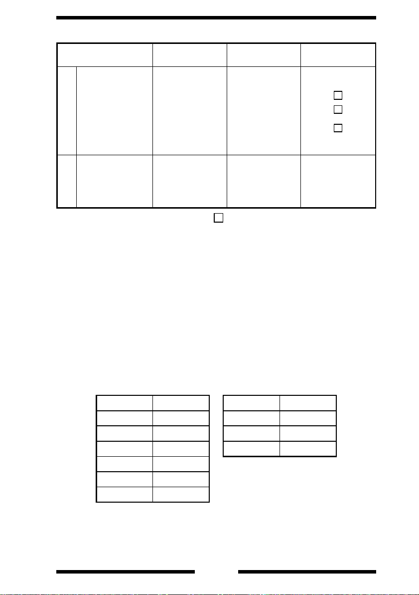
COPY MEDIUM :
Paper Source 1st to 2nd Drawer 3rd Drawer
Plain paper
(60 to 90 g/m
Translucent pap er — —
Transparencie s — —
MediumDimensions
Thick paper (90 to
157 g/m
Recycled paper O O O
Maximum
(Width × Length)
Minimum
(Width × Length)
2
)
2
)
OOO
——
297 × 432 mm A4C 297 × 432 mm
140 × 182 mm 8-1/2"×11"C 100 × 140 mm
Multi Bypass
Table
O: Permissible —: Not permissible : Conditionally permissible ... 20
sheets or less
L: Lengthwise, C: Crosswise
WARMING-UP TIME : 5 min. or less (with ambient temperature of 23°C or
WARMING-UP TIME
AFTER ENERGY
SAVER MODE
AUTO CLEAR TIME : Standard 1 mi n. (setting selectable from among 2 , 3,
FIRST COPY TIME : A4C or 8-1/2" × 11"C (Full s ize, fed from 1st Drawer ):
73°F and rated source voltage)
: 30 sec. or less (with ambient temperature of 23°C or
73°F and rated source voltage)
and 5 min.)
3.8 sec. or less
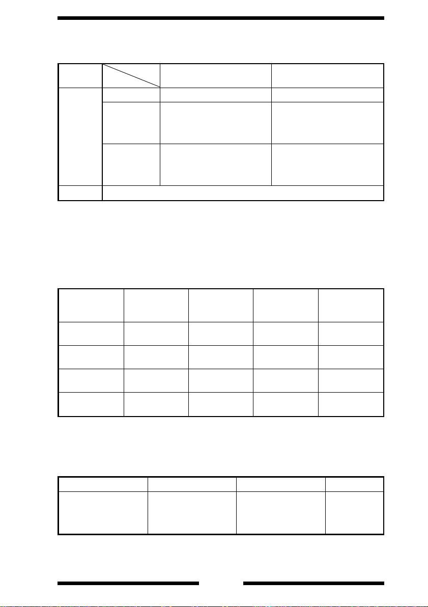
COPY SPEED : Full size
Metric Area Inch Area
Size copies/min. Size copies/min
A3L 31 11" × 17" 31
B4L 40 8-1/2" × 11"L 50
A4L 47 8-1/2" × 11"C 60
A4C 60
B5L 52
B5C 60
L: Lengthwise; C: Cro sswise
G-4
MULTIPLE COPIES : 1 to 999 cop ies ( coun t-do wn system)
ZOOM RATIOS
Area
Mode
Full Size ×1.000 ×1.000
Reduction
Fixed
Enlargement
Variable ×0.50 0 to ×2.000 (in 0.001 increme nts)
LENS : Through Lens (F=5.6, f=215 mm)
LIGHT SOURCE : Halogen frost tube lamp
FUSING
TEMPERATURE
POWER/CURRENT
CONSUMPTION
Voltage
115 V
120,127 V
200~220 V
220~240 V
::190°C (in copy cycle and standby)
180°C (in Energy Saver mode)
: Copier with full set of options
Exposure
Lamp (Rating)
90 V
220 W
90 V
220 W
160 V
250 W
160 V
250 W
Metric Inch
×0.816
×0.707
×0.500
×2.000
×1.414
×1.154
Fusing Roller
Heater Lamp
(Rating)
115 V
900 W
120,127 V
900W
200/220 V
1040 W
200/220 V
1040 W
Max. Power
Consumption
1320 W 1070 W
1370 W 1070 W
1620~1790 W 133 0 W
1590~1740 W 133 0 W
×0.785
×0.733
×0.647
×0.500
×2.000
×1.545
×1.294
×1.214
Power
Consumption
in Standby
POWER
REQUIREMENTS
ENVIRONMENTAL CONDITIONS :
Temperature Humidity Ambient Illumination Levelness
10 to 35°C
(50 to 95°F) with a
fluctuation of 10°C or
less per hour
: 115V, 120V, 127V, 200V, 220V, 230V, 240V; 50/60 H z
15 to 85% RH with a
fluctuation of 20% RH
or less per hour
3,000 lux or less
G-5
1°
(1.75/100)

DIMENSIONS : Copier only
WEIGHT : 195 kg or 430 lbs.
STANDARD
ACCESSORIES
OPTIONS : Large Capacity Cassette C-302
Width .... 746 mm or 29-1/4"
Depth .... 720 mm or 28-1/4"
Height ... 969 mm or 38-1/4"
(including the Duplexin g Do cum ent Feeder and PC Drum)
: Duplexing Document Feeder AFR-9, Toner Collecting
Bottle, Operator’s Manual, Starter , PC Drum
Exit Tray
20-Bin Sorter S-206
Staple Sorter ST-207
Data Controller DT-103
Data Controller D-102
Plug-In C ounter
Bias Seal
Original Cover
G-6
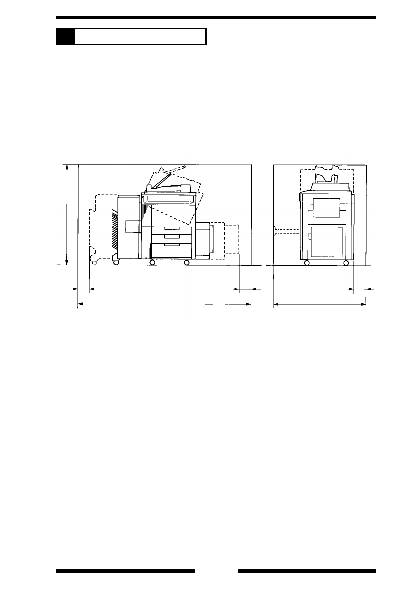
SPACE REQUIREMENTS
4
To ensure easy copier operation, supply replacement, and service
mainte nance, adh ere to the r ec omm e nd ed sp ace requirements det a i led
below.
*
Be sur e to allow a clearance of 150 mm (6") or mor e at the back of the
copier as t he re i s a ve nt i la t i on du ct.
1335 mm or 52-1/2"
200 mm or 7-3 /4 "
2844 mm or 112"
300 mm or 11-3/4"
150 mm or 6"
1342 mm or 52-3/4"
1075O127CA
G-7

PRECAUTIONS FOR INSTALLATION
5
Installation Site
To ensu re saf e t y and utm o st performa nc e of t he co pi e r, th e cop i er s ho ul d
NOT be us ed i n a pl a ce :
●
Where it will be subjected to extremely high or low temperature or
humidity.
●
Which is exposed to direct sunlight.
●
Which is in the direct air stream of an air conditioner, heater or
ventilator.
●
Which puts the operator in the direct stream of exhaust from the copier.
●
Which has poor ventilation.
●
Where ammonia gas might be generated.
●
Which does not have a stable, level floor.
●
Where it will be subject to sudden fluctuations in either temperature or
humidity. If a cold room is quickly heated, condensation forms inside
the copier, resulting in blank spots in the copy.
●
Which is ne ar any ki nd of h ea ti ng de vi c e.
●
Where it may be splashed with water.
●
Which is dirty or where it will receive undue vibration.
●
Which is near volatile flammables or curtains.
Power Source
Use an outlet with a capacity of 115/120/127V, 12A or more, or
200/220/230/240V, 8.5A or more.
●
If any ot her electrical equipm ent is sou r ced from t he same power
outlet, make sure that the capacity of the outlet is not exceeded.
●
Use a power source with lit tle voltage fluctuation.
●
Never connect b y means of a mu ltiple socket any other appli ances or
machines to the outlet being used for the copier.
●
Make the following checks at frequent intervals:
•
Is the po w er p lug abnorm a l ly h ot?
•
Are the r e an y cracks or sc rap es i n th e cor d?
•
Has the power plug been inserted fully into the outlet?
•
Does something, including the copier itself, ride on the power cord?
●
Ensur e that the copier does not ride on the po wer cord or
communications cable of other electrical equipment, and that it does
not become wedged into or underneath the mechanism.
Grounding
To preve nt r ec ei v i ng el e ct ri cal shocks in the ca se of elec tr i c al l eakage,
alwa ys ground the copier.
●
Connect the grounding wire to:
•
The gr ou nd t er mi n al o f t he ou t let .
•
A grounding contact which complies with the local electrical standards.
●
Never connect the grounding wire to a gas pipe, the grounding wire for
a telephone, or a water pipe.
G-8

PRECAUTIONS FOR USE
6
To ensure that the copier is used in an optimum condition, observe the
following precautions.
●
Never place a heavy object on the copier or subject the copier to
shocks.
●
Insert the power plug all the way into the outlet.
●
Do not attempt to remove any panel or cover which is secured while the
copier is making copies.
●
Do not turn OFF the Power Switch while the copier is making copies.
●
Provi de go od ve nt i la t i on w he n maki n g a l arge number of c op i es
continuously.
●
Never use f l amm a ble sprays ne ar th e cop i er .
●
If the copier becomes inordinately hot or produces abnormal noise, turn
it OFF and unplug it.
●
Do not turn ON the Power Switch at the same time when you plug the
power cord into the outlet.
●
When unplugging the power cord, do not pull on the cord; hold the plug
and pull it out.
●
Do not bri ng an y magnetized ob j ec t ne ar the copier .
●
Do not place a vase or ve ssel containing wate r on the copier.
●
Be sure to turn OFF the Power Switch at the end of the workday or
upon po we r fa i l ure.
●
Use ca r e n ot to dr op paper clips, s t aples, or other small p ieces of m etal
into the copier.
Operating Environment
The operating environmental requirements of the copier are as follows.
•
Temperature: 10°C to 35°C (50 to 95°F) with a fluctuation of 10°C per
hour
•
Humidity: 15% to 85% RH with a fluctuation of 20% RH per hour
Power Requirements
The power source voltage requirements are as follows.
•
Voltage Fluctuation: AC115/120/127/200/220/230/240V
±10% (Copying performance assured)
−15% (Paper feeding performance
assured)
•
Frequency Fluctuation: 50/60 Hz ±0.3%
G-9

HANDLING OF THE CONSUMABLES
7
Before using any consumabl e s, always read the label on its container
carefully.
●
Use the r i gh t toner. The applicabl e co pi e r model na m e is i nd i ca t ed on
the Toner Bottle.
●
Paper is apt to be easily damaged by dampness. To prevent
absorpt ion of moisture, store paper, which has been re m oved from i ts
wrapper but not loaded into the Drawer, in a sealed plastic bag in a
cool, dark place.
●
Keep consumables out of the reach of children.
●
Do not touch the PC Drum with bare hands.
●
Store the pa per, tone r , an d ot he r c on su m ab l es i n a place free f ro m
direct sunlight and away from a ny heati ng apparatus.
●
The same sized paper is of two kind s, short grain and long grain. Short
grain paper should only be fed through the copier crosswise, long grain
paper sh ou ld onl y be f ed l en gth w i se .
●
If your hands become soiled with toner, wash them with soap and
water immediately.
●
Do not throw away any used consumables (PC Drum, starter, toner,
etc.). They are to be collected.
NOTE
Do not burn, bury in the ground, or throw into the water any
consumables (PC Drum, starter, toner, etc.).
G-10
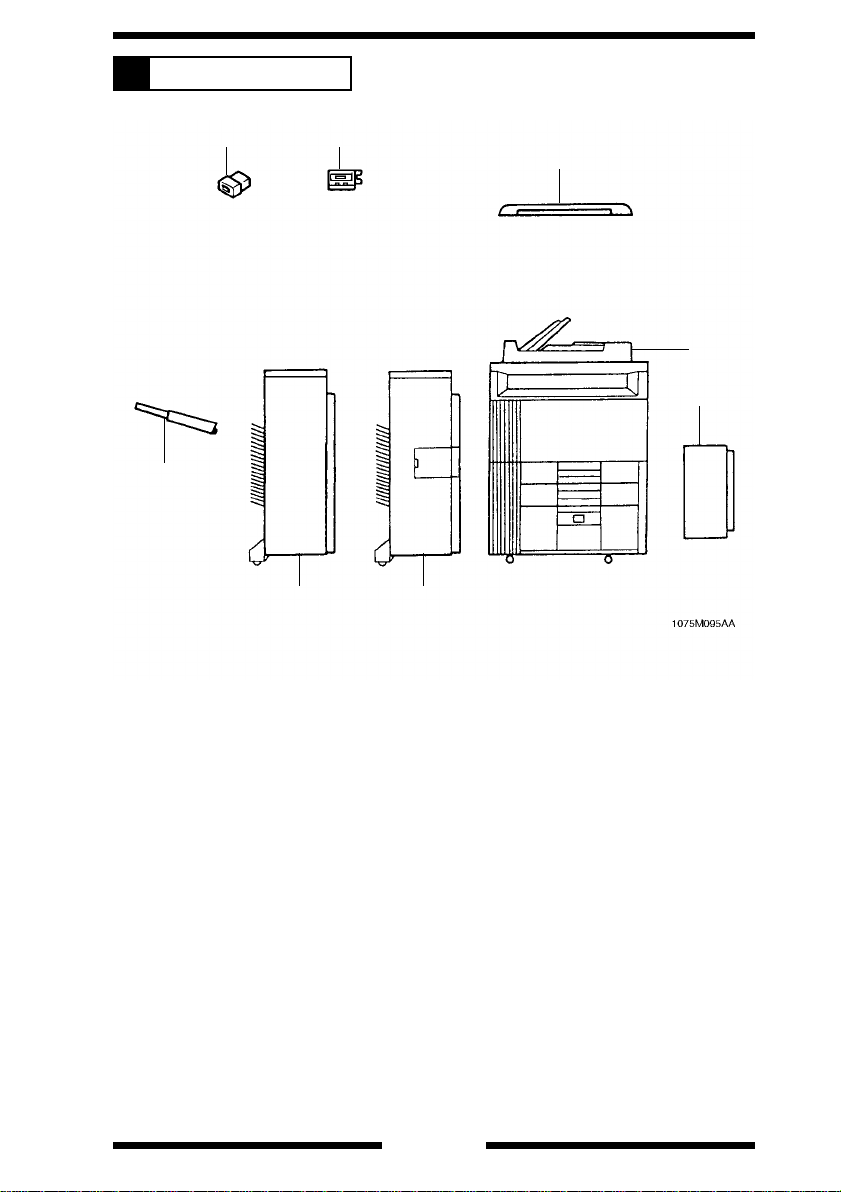
SYSTEM OPTIONS
8
1
8
1. Plug-In Counter
2. Data Controller D-102
3. Original Cover
4. Duplexing Document Feeder AFR-9 <Standard>
5. Large Capacity Cassette C-30 2
6. Staple Sorter ST-207
7. 20-Bin Sorter S-206
8. Exit Tray
2
76
3
4
5
G-11
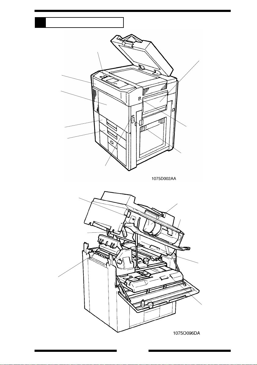
PARTS IDENTIFICATION
9
Control Panel
Upper Front Door
Lower Front Door
Manual Bypass Table
1st Drawer
2nd Drawer
Display Cont r ast
Control Knob
Lock Release Lever
Fusing Unit
Power Switch
Right Door Lock
Release Leve r
Total Counter
Toner Bottle
Toner Bottle Holder
PC Unit
G-12
Duplex Unit
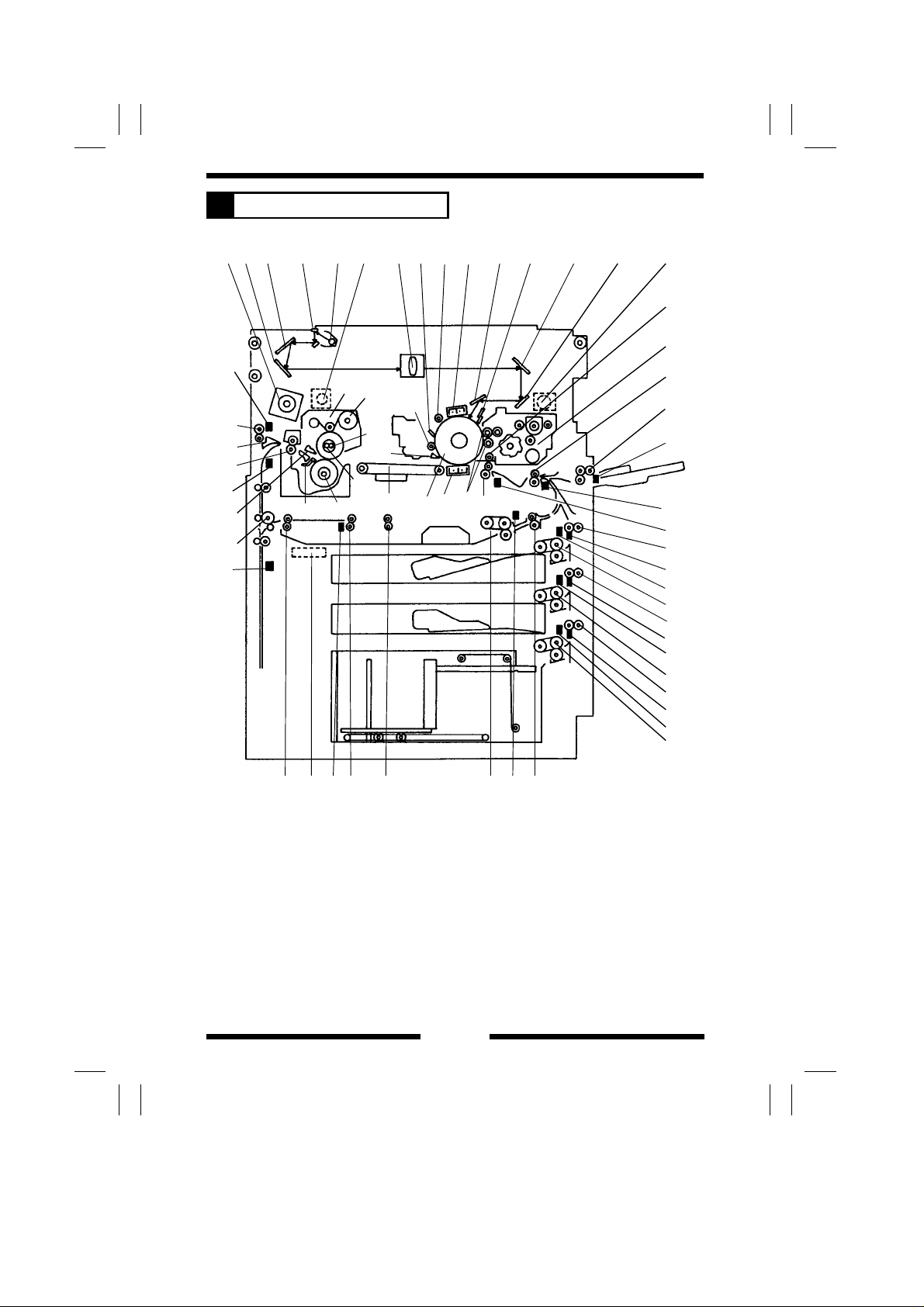
CROSS-SECTIONAL VIEW
1
36
35
34
E
33
37
F
32
56 7
27
28
29
25
30
31
26
10 11 12 1314
923 4 1615
8
22
23
24
20
21
17
19
18
A
B
C
44
I
J
45
46
K
L
47
48
M
N
49
1
D
G
4038 39 434241
H
1075M096AA
M-1

1. Optical Section Cooling Fan
Motor M17
2. 3rd Mirror
3. 2nd Mirror
4. 1st Mirror
5. Exposure Lamp LA1
6. Fusing Unit Ventilation Fan
Motor M8
7. Lens
8. Pre-Cleaning Erase Lamp LA5
9. Cleaning Blade
10. Main Erase Lamp LA2
11. PC Drum Charge Corona
12. 6th Mirror
13. 4th Mirror
14. Image Eras e Lamp LA 3
15. 5th Mirror
16. Toner Suction Fan Mot or M20
17. Developing Unit
18. Manual Bypass Take-Up Roll
19. Transport Roller
20. Synchroniz ing Roller
21. Pre-Image Transfer Erase
Lamp LA4
22. 1st and 2nd Sl eeve/Mag net
Rollers
23. Image Transfer/Paper
Separator Coronas
24. PC Drum
25. PC Drum Paper Separator
Finger
26. Suction Uni t
27. Fusing Unit
28. Web Roller
29. Upper Fusin g Rolle r Ma in
Heater La mp H1
30. Upper Fusin g Rolle r Sub
Heater La mp H2
31. Lower Fusing Roller Heater
Lamp H3
32. Lower Fusin g Paper Separator
Finger
33. Upper Fusin g Paper Se pa ra tor
Finger
34. Fusing Unit Transport Roller
35. Exit/Duplexing Switching Plate
36. Paper Exit Roller
37. Turnover/Paddles Roller
38. Turnover Drive Roller
39. Ventilation Fan Motor M19
40. Gate 2 Transport Roller
41. Gate 1 Transport Roller
42. Duplex Paper Take-Up Roll
43. Duplex Vertical Transport Roller
44. Vertical Transport Roller 1
45. 1st Drawer Paper Take-Up
Section
46. Vertical Transport Roller 2
47. 2nd Drawer Pa pe r Take-Up
Section
48. Vertical Transport Roller 3
49. 3 rd Drawer Pa per Take -Up
Section
- Misfeed Sensors -
A. Manual Feed P aper Empty
Sensor PC28
B. T ran spor t Roll er Sens or PC2 6
C. Paper Leading Edge Sensor
PC27
D. Paper Exit Sensor PC36
E. Transport Feed Sensor PC37
F. Duplex Unit Turnover Path
Sensor PC39
G. Duplex Unit Paper Entry
Sensor PC38
H. Duplex Unit Paper Take-Up
Sensor PC40
I. Vertical Transport Sensor 1
PC10
J. 1st Drawer Paper Take-Up
Sensor PC6
K. Vertical Transport Sensor 2
PC11
L. 2nd Drawer Paper Take-Up
Sensor PC7
M. Vertical Transport Sensor 3
PC12
N. 3 r d D r awer Pa per Take- Up
Sensor PC8
M-2
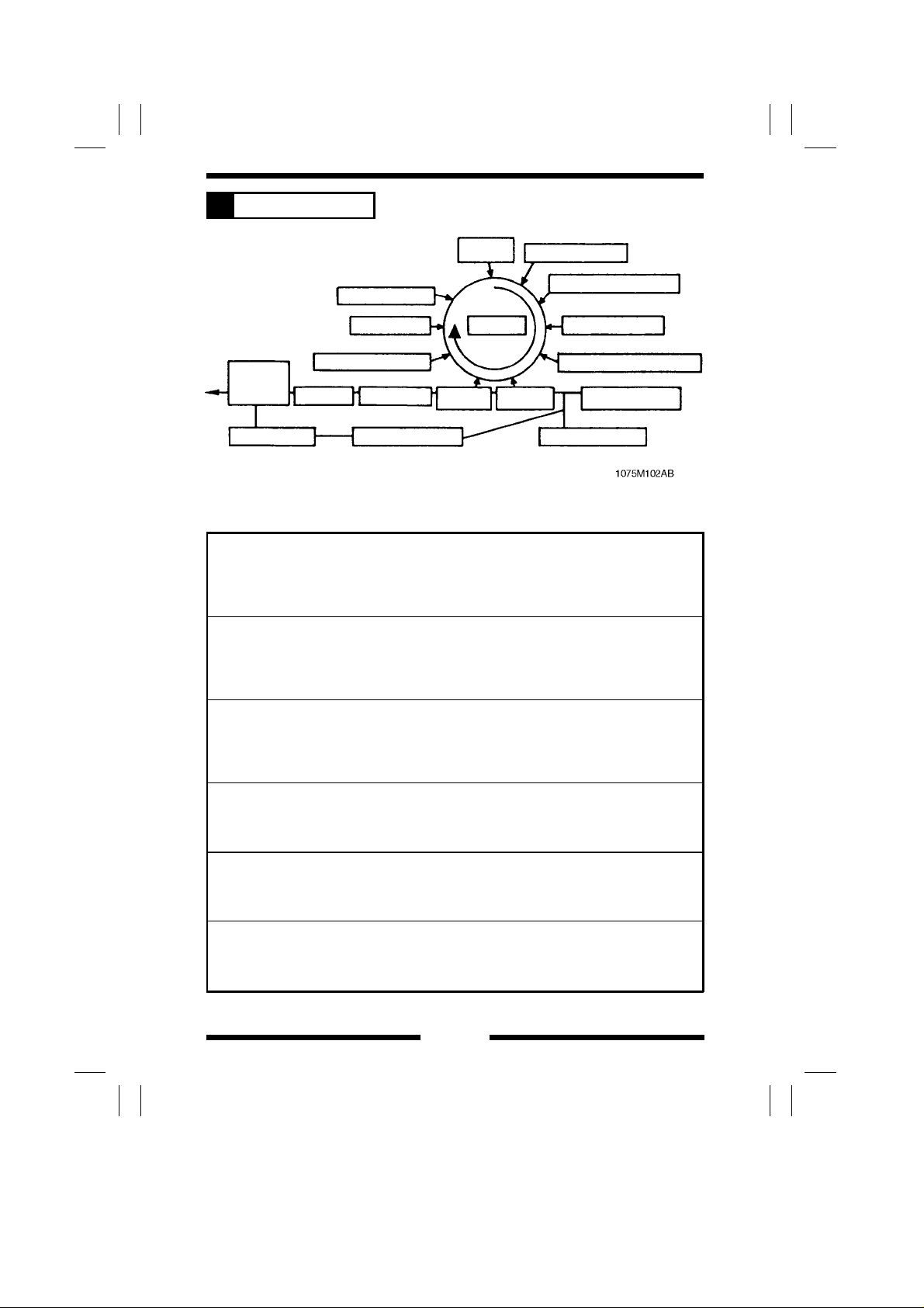
COPY PROCESS
2
15.
EXIT/DUPLEX
SWITCHING
16. TURNOVER
12. MAIN ERASE
11. CLEANING
10. PRE-CLE ANING ERASE
14. FUSING
13. TRANSPORT
17. DUPLEX UNIT
2. DRUM
CHARGING
1. PC DRUM
9. PAPER
SEPARATION
8. IMAGE
TRANSFER
3. EXPOSUR E
4. IMAGE ERASE
5. DEVELOPING
6. PRE-IMAGE TRANSFER ERASE
7. MULTI BYPASS
TABLE
7. PAPER FEEDING
1. PC Drum
The PC Drum is an aluminum cylinder coated with a photosensitive semiconductor.
It is used as the medium on which a visible developed image of the original is
formed.
(For more details, see p. M-25.)
2. Drum Charging
The PC Drum Charg e Co rona U nit is equipped with two corona wires a nd Scor otron
Grids to deposit a uniform negative charge across the entire surface of the PC
Drum.
(For more details, see p. M-28.)
3. Exposure
Light from the Exposure Lamp reflected off th e original is guided to the surface of
the PC Drum and reduce s the level of the negative charges, thereby forming an
electrostatic latent image.
(For more details, see p. M-34.)
4. Image Erase
Any areas of charge which are not to be developed are neutralized by lighting up
LEDs.
(For more details, see p. M-62.)
5. Developing
Toner positively charged in the Dev el oper Mixing Chamber is attracted ont o the
electrostatic latent image changing it to a visible, developed image.
(For more details, see p. M-69.)
6. Pre-Image Transfer Erase
Light from the Pre-Image Transfer Erase Lamp striking the surface of the PC Drum
improves image transfer and paper sep aration efficien cy.
(For more details, see p. M-93.)
M-3

7. Paper Feeding
Paper is fed from each drawer or Multi Bypas s Table.
(For more details, see p. M-95.)
8. Image Transf er
The single-wire Image Tr ans fer Corona Unit applies a DC negative corona e missio n
to the underside of the paper, thereby attracting toner onto the surface of the paper.
(For more details, see p. M-143.)
9. Paper Separation
The single-wire Paper Separator Corona Unit applies an AC corona emission [AC +
DC(+) bias voltage] to the underside of the paper to neutralize the paper.
(For more details, see p. M-143.)
In addition, mechanical paper separation is provided by the three PC Drum Paper
Separator Fingers.
(For more details, see p. M-155.)
10. Pr e-Cleani ng Erase
Light from the Pre-Cleaning Erase Lamp striking the surf ace of the PC D rum
reduces surface potential, thereby preventing toner accumulated on the back of the
Cleaning Blade fro m stickin g to the sur face of the PC Drum.
(For more details, see p. M-154.)
11. Cl eaning
Residual toner on the surface of the PC Drum is scraped off by the Cleaning Blade
and conveyed to the Tone r Collec ting Bottle.
(For more details, see p. M-150.)
12. Main Erase
Light from the Main Erase Lamp neutralizes any surface potential remaining on the
surface of the PC Drum after cleaning.
(For more details, see p. M-160.)
13. Tr ansport
The paper is fed to the Fusing Unit by the Suction Belts.
(For more details, see p. M-162.)
14. Fusi ng
The developed image is pe r manently fused to the paper by a combination of heat
and pressure applied by the Upper and Lower Fusing Rollers.
(For more details, see p. M-164.)
15. Exit/Duplex Switching
After the fusing process the paper is eit her fed out onto th e Exit Tray o r down into
the turnover mechanism of the Duplex Unit.
(For more details, see p. M-178.)
16. Tur nover
The 1-sided copy is turned over and fed into the Duplex Unit.
(For more details, see p. M-181.)
17. Dup l ex Unit
The 1-sided copies are stored and th en tak en up one by one for th e secon d copy
cycle.
(For more details, see p. M-186.)
M-4
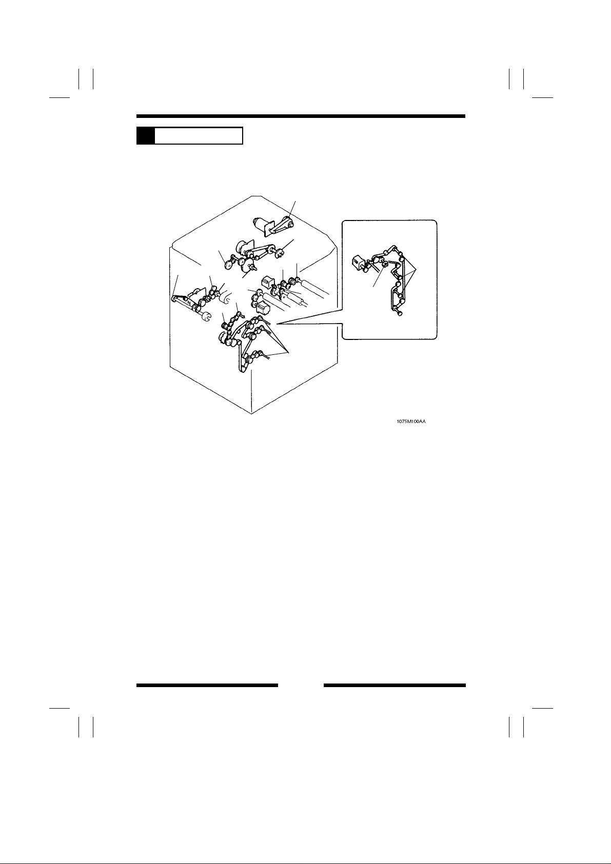
DRIVE SYSTEM
3
7
C
B
4
1
2
A
3
12
13
F
D
5
11
6
G
8
9
10
E
14
16
15
M-5

A = Fusing Motor M6: Drives the Fusing Unit, Paper Exit Roller, and Suction
Belts.
1. Paper Exit Roller drive pulley
2. Fusing Unit drive gear
3. Suction Belt drive gear
B = PC Drum Drive Motor M5: Drives the PC Drum, Developing Unit, and
Toner Conveying Screw.
4. Toner Conv eying S cr ew driv e g ear
5. PC Drum drive coupling pawl A
6. Devel op i ng Un i t dr i ve co upling ge ar 2
C = Scanner Motor M1 1: Dr ives the S ca nner and 2n d / 3 r d M i rr or s Carriage.
7. Scanner dr ive pul ley
D = Tra nsport Mo t or M3: Drives the Transport Ro ller and Multi Bypass
Take-Up mechanism.
8. Mult i By pass Take-Up drive gear
9. Mult i Feed Pape r Take-Up Clutch CL5
10. Tr ansport Roller d r ive gear
E = Sync hronizi n g Mo t or M 4 : D r ives t he Synchronizing Roller
11. Synchronizing Roller drive gear
F = Paper Take-Up Motor M1: Drivers the Paper Take-Up mechanism and
the Duplex Take-Up mechanism.
12. Dup lex Take-Up mech anism drive gear
13. Duplex Unit Paper Take-Up Clutch CL6
14. Paper Take-Up Clut ch for dr awers CL1 to 3
G = Vert i cal Tran sport Motor M2 = D r ives the Vertical Transport Rollers and
Duplex Vertical Transport Rollers.
15. Vertical Transport Roller drive gear
16. Dup lex Vert ical Tr ansport Ro ller dr ive gear
M-6
SEQUENTIAL EXPLANATION
4
A The power cord is plugged into the outlet.
ON
B Power Switc h S 1 i s turned ON .
OFF
ON
ON
ON
Approx. 1 sec.
DC Power Supply 1 PU2 outputs DC24V for dehumidifiers.
ON
Drum Dry Heater H4, Lower Paper
Dehumidifying Heater H5, and Upper
Paper D ehumidi fying Heater H7
ON
Developing Unit Dehumidifying Heater
H6
H4, H5, H7, H6
PU2 outputs DC24V and DC5V.
ON
DC Power Supply Board PWB-C outp uts
DC24V. (DC24V line: ON)
ON
Master Bo ar d PWB-A outpu ts DC4. 7 V and DC12V .
Control panel display
Suction Fan Motor M18 turns at half speed.
ON
Upper Fusing Roller Main/Sub Heater Lamp H1/H2
The Lens is detected at the home position.
The Mirror is detected at the
home position.
The Scanner makes its initial motion.
The Lens is detected at the
full size position.
The Mirror is detected at
ON
Approx.
24 sec.
the full size position.
PC Drum Charge Wire Cleaning Motor / Image
Transf er/Pap er Separat or Charge Wire Cleanin g Motor
M21/M22
OFF
*
Only when Drum
Dehumi dif y i ng S wi tch
S9 and Pape r
Dehumi dif y i ng S wi tch
S10 are ON.
For details, see
OPTICAL SECTION.
M21, M22: Cleaner makes one round tr ip to
clean the wire and stops.
One-Shot Correction mode (For details, see
p. M-24.)
The surface temperature of the Upper Fusing Roller reaches 170°C.
ON
Fusing Motor M6 starts predrive.
➀
M-7
➀
After 85 se c. or
40 sec. or 5 sec.
OFF
M6
ON
Fusing Unit Ventilation Fan Motor M8
= The following sequence is when making a single copy in full size on A4
crosswise fed from the 1st Drawer. =
The Start Key is pressed .
C
(A4 crosswise pape r fed from 1st Drawer , full size, single copy cycle)
ON
M6
Approx.
5 sec.
ON
Paper Take-Up Motor / Vertical Transport Motor / Transport
Motor M1/M2/M3
ON
1st Draw er Paper Take-Up Clutch CL1
*
Timing depends on the surface temperature of the
Upper Fusing Ro ller and the diff erence in surface
temperature between the Upper and Lower Fusing
Rollers when S1 is turned ON.
(For details, see p. M-175.)
ON
PC Drum Drive Motor M5
ON
Developing Bias
ON
Optical Section Cooling Fan Motor / Ventilation Fan
Motor / Toner Suction Fan Motor / Power Supply
Unit Cooling Fan Motor M17/M19/M20/M29
Suction Fan Motor M18 turns at full speed.
Approx. 250 msec.
Approx. 350 msec.
Approx. 400 msec.
Approx. 450 msec.
ON
Image Transfer/Paper
Separator Coronas
Exposure Lamp / Image
Erase Lamp LA1/LA3
ON
Main Erase Lamp LA2
ON
PC Drum Charge Corona
ON
Pre-Image Transfer Erase
Lamp / Pre-Cleaning Erase
Lamp LA4/LA5
Vertical Transport Sensor 1 PC10 is blocked ( L ).
Approx. 60 msec.
Paper Leading Edge Sensor PC27 is bl ocked ( L ).
Approx. 50 msec.
OFF
OFF
CL1, M1
M2, M3
M-8
PWB-A outputs a LOW SCAN signal to Scanner Control
D
Processor Board PWB-J.
The Scanner starts a scan motion.
A LOW Image Leading Edge signal is input to PWB-A.
ON
LA3
Approx. 65 msec.
E PWB-J outputs a LOW TRON signal to PWB-A.
ON
M3/M4
Approx. 120 msec.
OFF
LA3 ... Leading edge erase
ON
Sepa r ator Finger Sol enoid SL6
Approx. 280 msec.
F PWB-J outputs a LOW SCEND signal to PWB-A.
Approx. 200 msec., the SCEND signal goes HIGH.
SCAN signal: H ... The Scanner stops and starts a return motion.
Scanner Reference Position Sensor PC1 is blocked ( L ).
Approx. 50 msec.
Approx. 80 msec.
Approx. 570 msec.
Approx. 690 msec.
Approx. 1,050 m sec.
OFF
LA1
OFF
PC Drum Charge Corona
OFF
Image Transfer/Paper Separator Coronas
OFF
LA4/LA5
OFF
LA2/LA3
M5
Approx. 1,350 msec.
OFF
Developing Bias
OFF
SL6
M-9

The trailing edge of the paper moves past Transport Roller Sensor PC26
G
(unblocked: H ).
Approx. 144 msec.
The trailing edge of the paper moves past Paper Leading Edge Sensor
H
PC27 (unblocked: H ).
Approx. 90 msec.
The trailing edge of the paper moves past Paper Exit Sensor PC36
I
(unblocked: H ).
Approx. 600 msec.
Approx.
4,600 msec.
OFF
M3
OFF
Synchronizing Motor M4
OFF
M6
OFF
M17/M19/M20/M29
M18 turns at half speed.
M-10
WATCHDOG (CPU OVERRUN MONITOR) FUNCT ION
5
5-1. Overview
The wat c hd og f un ct ion monitor s wh et h er a ny of t h e CPU s mo un ted i n th e
copier overrun. If this function detects that a CPU overruns, the copier
automatically resets the CPU, thereby restarting the logic circuit and
mechanism.
Even if a cop ier CP U oper a tes errati c al l y du e to electri ca l noi se , the r efo r e ,
the copier is able to recover from the faulty condition so that the number of
visits made by the Technical Representati ve for CPU overrun can be
minimized.
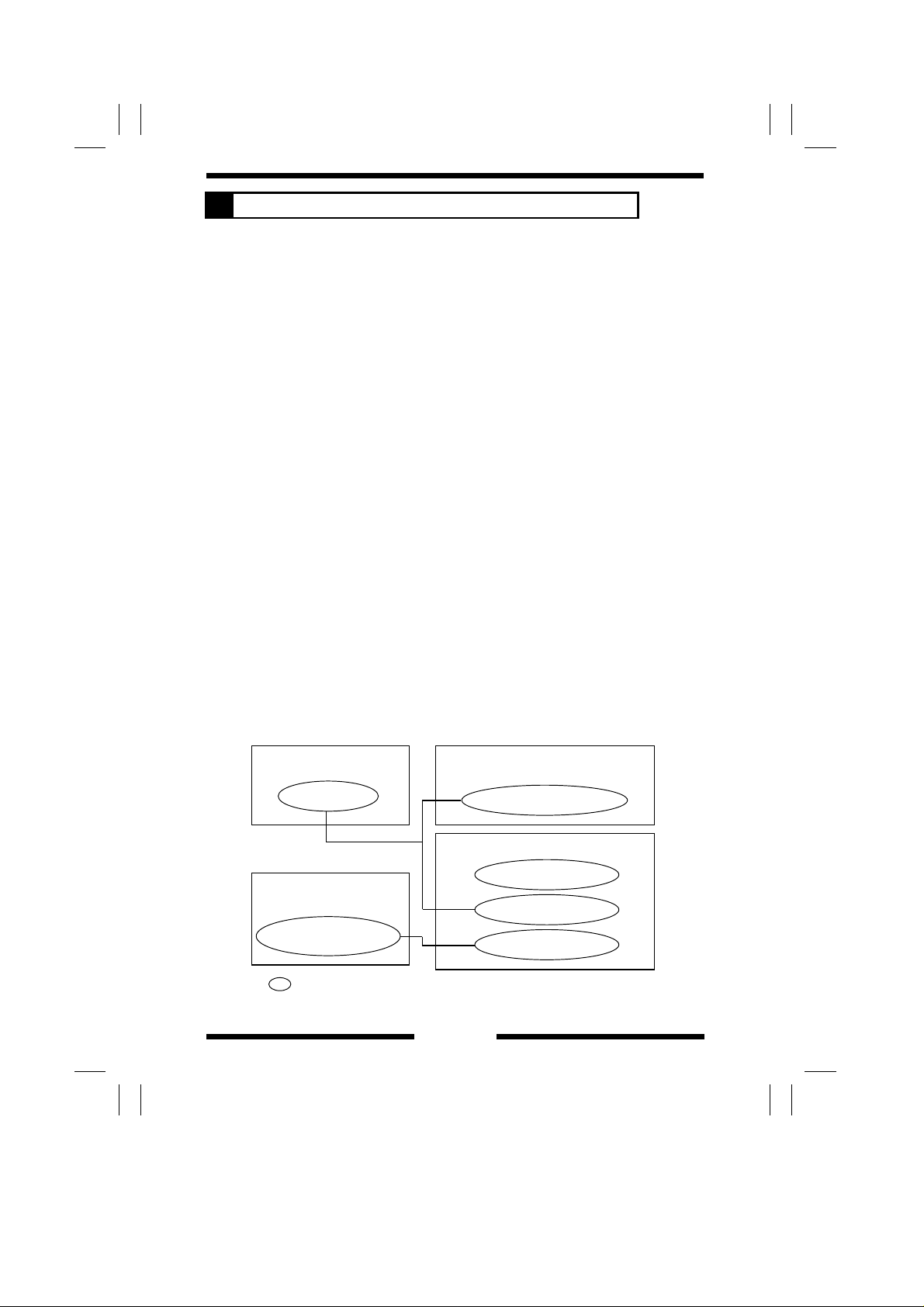
5-2. Configuration
The copier has three print ed-circuit boards each on which a CPU is mounted:
*
SCP (Scanner Control Processor) Board PWB-J that controls the optical
system;
*
MSC (Macro System Controller) Board PWB-B that controls the co ntr ol
panel and system ; and,
*
Master Bo ar d PWB-A .
In addition to these, each of the control boards for the Data Controller,
Duplexi ng Docum ent Feeder, and Sorter/Staple Sorter is equipped with a
CPU.
The watchdog functions are summarized as follows:
*
Each of t he copie r CPUs monitors whethe r or not i t overr uns.
*
The PWB-B monitors the communications conditions of the CPUs in the
Duplexing Document Feeder and Data Controller.
*
The PWB-A monitors the communications conditions of the CPUs in the
Sorter and Staple Sorter.
Data Controller
Control Board
Sorter, Staple Sorter
Control Board (PWB-A)
Board on which a
=
CPU is mounted
Duplexing
Document Feeder
Control Board (PWB-A)
Copier
SCP Board PWB-J
MSC Board PWB-B
Master Board PWB-A
M-11
5-3. Watchdog Funct i on Post-Processing
The following processing is performed if a faulty condition is detected in the
CPU. The Watchdog Counter available from the Tech. Rep. mode allows the
Techn i cal Represe ntati ve to check if any faulty condition has occurred in the
CPU. For details, see SWITCHES ON PWBs.
Faulty CPU Processing (in Standby)
Copier
Sorter,
Staple Sorter
1 : The CPU is autom atically r eset (i.e.,
shutting down power to all CPUs
including those in the op tio ns ) as
soon as a faulty CPU is detected.
1 : When the CPU malfun ct ions, t he
communication to Master Board
PWB-A of the copier is cut o ff or
faulty data is transmitted to the
PWB-A.
2 : The PWB-A detects that the CPU of
the Sorter or Staple Sorter is faulty.
3 : The PWB-A notifies MSC Board
PWB-B that the CPU of the Sorter or
Staple Sorter is faulty.
4 : As commanded by the PWB-B,
Option Relays RY3C and 4C are
turned OFF and ON t o rest art the
option.
5 : The communicat ion line fr om the
CPU of the Sorter or Staple Sorter to
PWB-A is recovered.
6 : PWB-A notifies PWB-B that the CPU
of the Sorter or Staple Sorter has
recovered from the faulty condition.
Processing
(during Copy Cycle)
1: Same as 1 on the left.
2: Since the paper is left
inside the copier, th e
copier detects a misfed
sheet of paper or two
when power is turned
ON again. If the MSC
CPU is faulty, however,
all paper in line f or the
exit will be ejecte d and
all paper headed to the
duplex will be stored,
before restarting the
CPU.
1 : Same as 1, 2, and 3 on
the left.
2 : The paper take-up
sequence is stopped.
3 : All sheets of paper
being fed through th e
copier are fed out of
the copier.
4 : Same as 4, 5, and 6 on
the left.
M-12
 Loading...