

Page 1
Electrical.fm Page 1 Thursday, September 19, 2002 8:44 AM
123456789101112131415
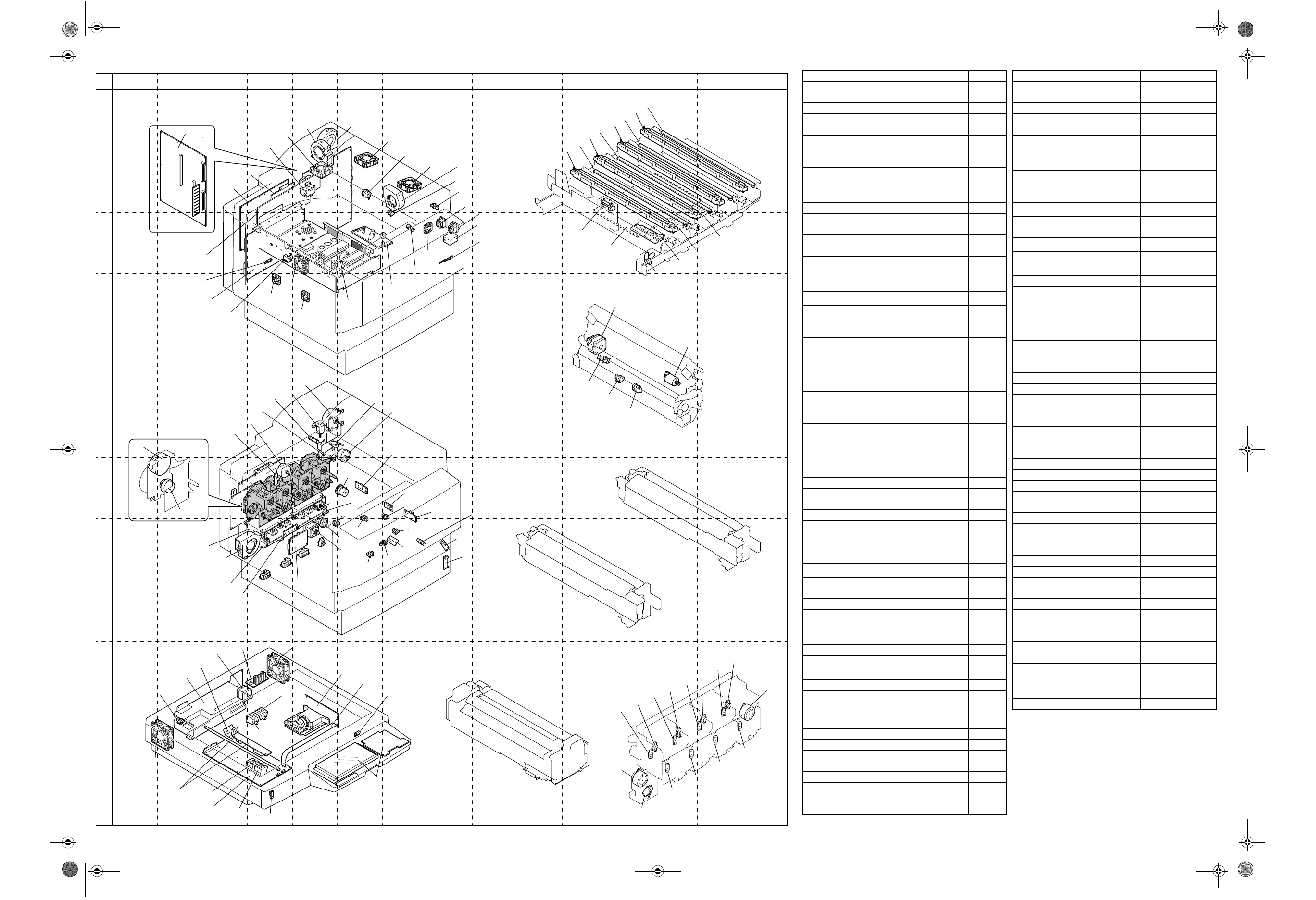
ELECTRICAL PARTS LAYOUT
A
B
C
D
E
F
G
H
J
K
L
PWB-F
M27
M26
RY1
PWB-G
PWB-IO
HV2
TH3
PWB-PIC
SW4
M21
M29
M28
M14
M8
PC8
M13
M11
PC28
M15~18
CL11~14
HV1
M22
SW D
SW C
SW B
HV3
SW A
PWB-A
PWB-I
I
M203
PC206
PC201
PC202
M202
Exposure Unit
PU201
PC203
PC205
PWB-C
M201
PWB-IC
PC204
PC207
PC4
PC104
CL101
M101
PWB-A
M24
M31
PU2
PU1
SW2
M19
UN21
CL1
PC3
PC103
PC6
PC5
PWB-B
SW201
UN201
4025D107AC
CL3
PC12
UN23
PC105
PC13
M30
M25
4025D100AC
UN20
PC102
4025D099AA
M23
PC15
PC10
SW9
SW1
CNT12
PWB-S1
PC101
PWB-S
UN101
Fusing Unit
LPH Unit
LA7
UN M
LA6
UN Y
PC29
PWB-LED
2nd Transfer Unit
PC23
PC14
Imaging Unit (Y, M, C)
4025D140AA
LA9
UN Bk
LA8
UN C
M20
PC19
Hopper Unit
PC48
PC40
M10
SW3
PC18
PC42
PWB-N1
M12
4025D101AA
PC44
PC49
PC41
PWB-N3
PWB-N2
4025D102AB
Imaging Unit (Bk)
4025D139AA
PC51
PC46
PC50
PC47
PC45
PC43
4025D105AA
M9
SYMBOL PART NAME LOCATION GRID
CL1 1st Drawer Paper Take-Up Clutch A-8 G-5~6
CL3 Manual Feed Paper Take-Up Clutch A-1~2 B-6
CL11 Developing Clu tch Y A~B-16 G-2
CL12 Developing Clu tch M B-18 G-2
CL13 Developing Clu tch C C-17 G-2
CL14 Developing Clut ch Bk C~D-18 G-2
CL101 2nd Drawer Paper Take-Up Clutch I-5 G~H-5
CNT12 Total Counter E-36 C-8
HV1 High Voltage Unit (PC Drum CH.) A~B-21~22 G~H-4~5
HV2
HV3 High Voltage Unit (Developing Bias) B~C-19~20 G~H-4~5
LA6 Main Erase Lamp Y B-10 B~C-11~13
LA7 Main Erase Lamp M B-10 B~C-12~14
LA8 Main Erase Lamp C B-10 A~B-12~14
LA9 Main Erase Lamp Bk B-10 A~B-13~15
M8 Fusing Pressure/Retraction Motor E-2 F-5
M9 Toner Replenishing Motor C/Bk A-10 K-14~15
M10 Toner Replenishing Motor Y/M A-10 L-12
M11
M12
M13 Main Motor A-35~36 F~G-5
M14 Fusing Drive Motor E-2 F-5~6
M15 IU Motor Y A~B-16 F~G-1~2
M16 IU Motor M B-17 F~G-1~2
M17 IU Motor C C-16 F~G-1~2
M18 IU Motor Bk C~D-18 F~G-1~2
M19 Synchronizing Roller Motor H-2 F~G-6
M20 Transport Roller Motor H-2 E-11
M21 Power Supply Cooling Fan Motor I-28~29 C~D-5
M22 Ozone Ventilation Fan Motor A-19 H-3~4
M23 Suction Fan Motor G~H-2 B-7
M24 Fusing Cooling Fan Motor F-2 A-5~6
M25 Cooling Fan Motor 1 A-35~36 C-7~8
M26 Cooling Fan Motor 2 B-35~36 B-5
M27 Cooling Fan Motor 3 B-35~36 A~B-5
M28 Cooling Fan Motor 4 B-35~36 D-5
M29 Cooling Fan Motor 5 B~C-35~36 D-4
M30 Fusing Roll Cooling Fan Motor 1 F-2 B-7
M31 Fusing Roll Cooling Fan Motor 2 F~G-2 B-6
M101 2nd Drawer Paper Take-Up Motor G-6 H-5
M201 Scanner Motor G-22 J-3~4
M202 IR Power Supply Cooling Fan Motor G-19~20 K-1~2
M203 IR Drive Board Cooling Fan Motor G~H-19~20 J-4
PC3 1st Drawer Set Sensor C-8 G-5
PC4
PC5 CD Paper Size Detecting Sensor B-8 H-6
PC6 1st Paper Empty Sensor A~B-8 H-6~7
PC8 Fusing Retraction Position Sensor G-2 F-5
PC10 Exit Sensor E~F-8 B-8
PC12
PC13 1st Drawer Double Feed Sensor C-8 H-7
PC14 Synchronizing Roller Sensor I-2 E-12
PC15
PC18 Waste Toner Bottle Set Sensor F-35 C-12
PC19 OHP Detecting Sensor H~I-2 E-12
PC23
PC28
PC29 Waste Toner Full Detecting Sensor F~G-35 B-11~12
PC40 Toner Near-Empty Sensor LED Y C-12 K-12
PC41 Toner Near-Empty Sensor PQ Y A-12 L-13
PC42 Toner Near-Empty Sensor LED M C-12 K-13
PC43 Toner Near-Empty Sensor PQ M A-12 K-13
PC44 Toner Near-Empty Sensor LED C B~C-12 K-14
PC45 Toner Near-Empty Sensor PQ C A-12 K-14
PC46 Toner Near-Empty Sensor LED Bk C-12 K-14
PC47 Toner Near-Empty Sensor PQ Bk A~B-12 K-14
High Voltage Unit (Image Transfer,
Neutralizing)
1st Image Transfer Pressure/
Retraction Motor
2nd Image Transfer Pressure/
Retraction Motor
1st Drawer Paper Near-Empty
Sensor
Image Transfer Belt Reference
Position Sensor
Manual Feed Paper Take-Up
Sensor
2nd Image Transfer Pressure
Position Sensor
1st Image Transfer Retraction
Position Sensor
A~C-5~6 B~C-4~5
D-5 G-4
D-5 E-13
B-8 G-5
D~E-5~6 C-7
A~B-1~2 B~C-7
E-5~6 E-11~12
E-5~6 G-4
SYMBOL PART NAME LOCATION GRID
PC48 TC Set Sensor Y D-12 K-13
PC49 TC Set Sensor M B-12 K-13
PC50 TC Set Sensor C B-12 K-14
PC51 TC Set Sensor Bk D-12 J~K-14
PC101 2nd Drawer Paper Take-Up Sensor H-6 H-7
PC102 2nd Drawer Paper Empty Sensor I-6 H-7
PC103
PC104 2nd Drawer Door Set Sensor H~I-5 H-5~6
PC105 2nd Drawer Double Feed Sensor H-6 G~H-7
PC201 Scanner Home Sensor G-26 L-4
PC202 Original Cover De tecting Sen sor H-19~20 K-2
PC203
PC204 Original Size Detectin g Sensor F D2 I-19~20 K-3~4
PC205 Original Size Detecting Sensor C D1 F-2 5~ 26 K~L-3~4
PC206
PC207
PU1 DC Power Supply 1 E~I-28~30 C-5~6
PU2 DC Power Supply 2 E~F-30~31 C-6~7
PU201 DC Power Supply 3 H~I-21~22 J~ K-2~3
PWB-A Control Board G~I-7~8 H-4~5
PWB-A CCD Sensor Board A-24~26 J~K-4~6
PWB-B Image Processing Interface Board – K~L-4~5
PWB-C I mage Pr ocessing Boa rd B~F-24~27 K~L-3~4
PWB-F Image Control Board A~C-30~31 A~C-2~3
PWB-G Option Interface Board B~E-28~30 B-4~5
PWB-I Paper Size Detecting Board D~E-7~8 H-4~5
PWB-IC Scanner Motor Drive Board F~G-21~22 J-3~4
PWB-IO IO Board E~I-10~18 B~C-3~4
PWB-LED LED Drive Board C~E-20~22 B~C-11~14
PWB-N1 ATDC Sensor Y B~C-10 C-12~13
PWB-N2 ATDC Sensor M C-10 C-13
PWB-N3 ATDC Sensor C C~D-10 B~C-13~14
PWB-PIC PIC Board B~D-32~33 A~D-4~6
PWB-S Paper Type Detection Board C~D-7~8 H-8
PWB-S1 Tech. Rep. Setting Switches Board E~F-35~36 C-8
RY1 Charge Neutralizing Relay A-4~5 B-5
SW A Paper Size Detecting Switch 1 H-9 H~I-4
SW B Paper Size Detecting Switch 2 H-9 H-4
SW C Paper Size Detecting Switch 3 I-5 H-5
SW D 2nd Drawer Set Switch H-5 H-5
SW1 Power Switch C-36 C-8
SW2 Right Door Switch D-36 F-5~6
SW3 Front Door Switch D-36 L-12~13
SW4 Left Door Switch C-36 C-4
SW9 Upper Right Door Switch D~E-23 C-8
SW201 Size Reset Switch G-26 K-6
TH3 Image T r ansfer Thermistor E~F-5~6 C-4
UN Bk LPH Assy Bk D-22 A~B-12~15
UN C LPH Assy C D-21 A~B-12~14
UN M LPH Assy M D-20~21 B~C-11~14
UN Y LPH Assy Y D-20 B~C-11~13
UN20 AIDC/Resist Sensor 1 C-5 G~H-7
UN21 AIDC/Resist Sensor 2 C-5 G-6
UN23 Temperature/humidity Sensor D-14 G-7
UN101
UN201 Control Panel F~G-23~25 K~L-5~7
2nd Drawer Paper Near-Empty
Sensor
Original Size Detecting Sensor FD 1
(OP:USA )
Original Size Detecting Sensor FD 3
(OP:Europe, USA, Taiwan)
Original Size Detecting Sensor CD2
(OP:Europe, USA, Taiwan)
2nd Drawer Paper Near-Empty
Board
– Exposure Unit G~I-24~27 K~L-3~4
H~I-6 G~H-6
H~I-19~20 K-3
G-19~20 K-4
F-19~20 K~L-4
G~H-6~7 H-8
4025-B301-1A
Page 2
Connect.fm Page 1 Thursday, September 19, 2002 8:44 AM
12345678910111213 1514
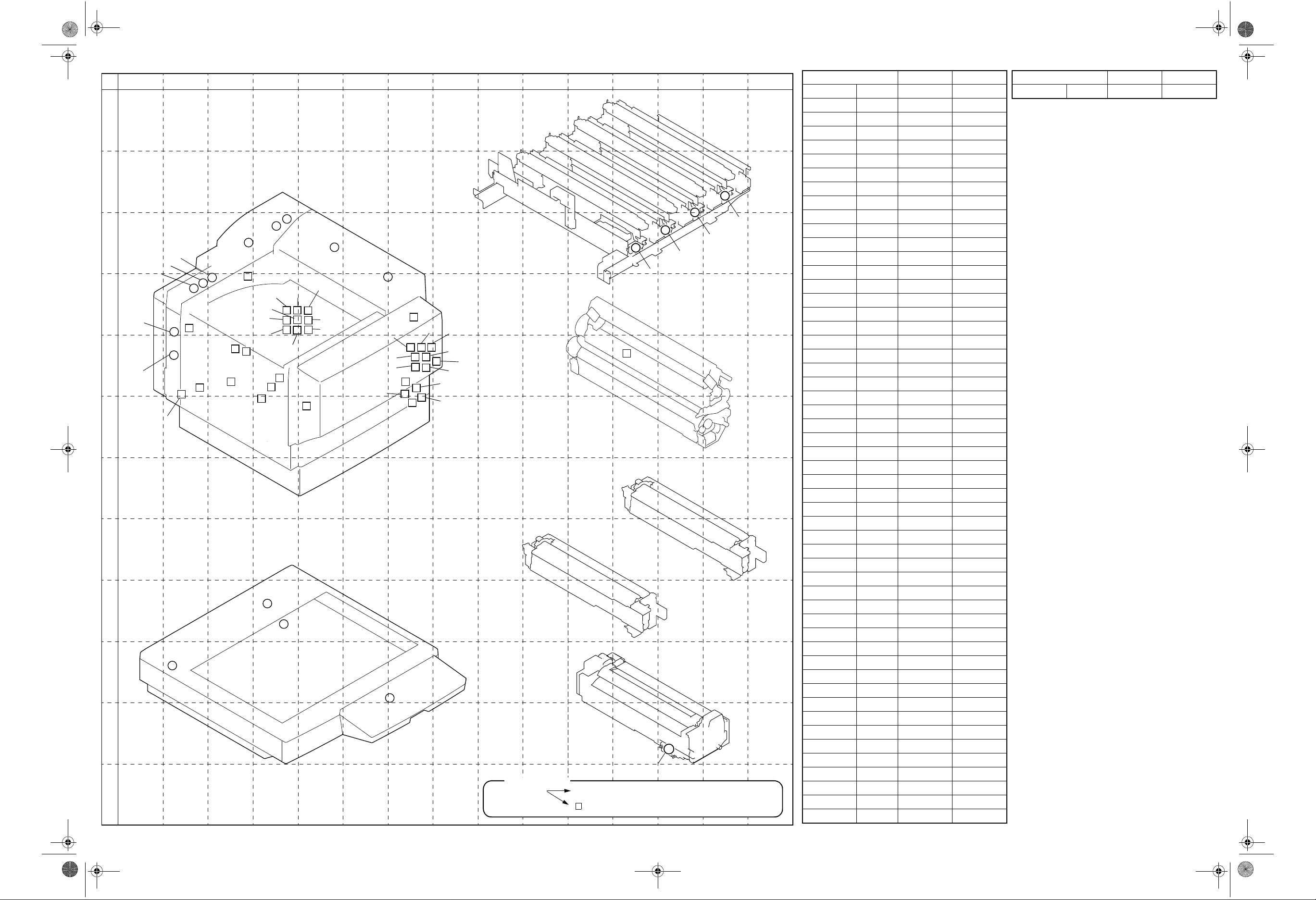
CONNECTORS LAYOUT
A
B
CN2
CN40
CN1
3
3
CN46
4
3
CN38
2
4
CN45
3
CN13
4
3
9
11
2
8
CN3
2
3
5
4
3
CN92
CN41
CN14
CN43
C
D
E
F
G
H
J
K
L
CN80
3
CN32
3
CN81
CN11
2
CN12
4
3
CN61
CN50
CN33
CN8
CN39
CN88
CN42
CN87
CN30
CN37
CN49
CN22
8
6
CN23
6
9
2
CN89
10
4
3
I
CN47
3
CN56
3
CN91
CN26
CN28
CN6
CN44
CN48
CN18
4
6
4025D094AC
2
3
14
4
4
10
4
CN54
CN27
14
3
CN21
2
CN31
5
2
3
CN17
CN29
CN35
4025D106AB
CN90
LPH Unit
8
8
8
CN15
CN16
2nd Transfer Unit
4
CN9
Imaging Unit (Bk)
Imaging Unit (Y, M, C)
Fusing Unit
24
CN4
Description
Number of Pin Possible to confirm by removing external cover.
➀
Not possible to confirm by removing external cover.
1
12
CN10
4025D096AB
4025D095AB
4025D139AA
4025D141AA
CN19
CN No. L OCATION GRID
CN1 2P I-5 E-4
CN2 3P F-2 C-4
CN3 4P A-10 F-5
CN4 24P C~D-3 K-13
CN6 4P A-11 E-7
CN8 3P H-2~3 D-4
CN9 4P H-2 E-12
CN10 8P C~D-23 B~C-13
CN11 3P B-35 C-3
CN12 3P I-28 E-3
CN13 2P A-9 D-4~5
CN14 3P H-2~3 D-5
CN15 8P A-23 C-12
CN16 8P B-23 C-13
CN17 3P F-9 E-7
CN18 3P A-35 D-7
CN19 12P B~C-13 B-14
CN21 2P E-35 E-7~8
CN22 10P E~F-35 D-3
CN23 2P E~F-6 D-2
CN26 14P A~B-13 E-7
CN27 14P C~D-13 E-7
CN28 4P A-11 E-7
CN29 10P C-6 E-7
CN30 4P G-34 D-2
CN31 5P D-35 E-7
CN32 2P C-35 E-3
CN33 8P A~B-2~3 D-4~5
CN35 3P D~E-6 E~F-7
CN37 9P D~E-34 D-2
CN38 11P G-8 D-4~5
CN39 9P H~I-3 D-4
CN40 4P H-2~3 D-4
CN41 2P A-2 D-5
CN42 8P F-34 D-2
CN43 5P D-6 D-5
CN44 4P D-13 E-7
CN45 4P A-26 I-4
CN46 3P G~H-20 I-4
CN47 3P G-20 J-2
CN48 2P G-26 J-6~7
CN49 6P D-19 E ~F-2
CN50 4P D-6 C~D-3
CN54 4P C-9 F-7
CN56 6P A~B-9 E~F-7
CN61 4P F~G-6~7 E-4
CN80 3P B-35 C-4
CN81 3P G-7~8 E-3
CN87 6P B-35 E-2
CN88 3P B-35 E~F-4
CN89 3P B~C-35 E-2
CN90 2P E-8 E-8
CN91 3P F-2 C~D-6~7
CN No. LOCATION GRID
CN92 3P F~G-2 C-5
4025-B401-1A
 Loading...