

Konica Minolta CF2001, CF1501 User Manual
UNIT REPLACEMENT
MANUAL
18605


CONTENTS
1. The Unit Life Manual ........................................................................................1
2. The Indication of Replacement for CRU/TFU/FRU ..........................................1
3. Unit Replacement Manual ...............................................................................1
3-1. Unit Layout ...............................................................................................1
3-2. Replacing the Units ..................................................................................2
(1) Replacing the Fusing Web Unit .......................................................2
(2) Replacing the Oil Coating Unit ........................................................ 6
(3) Replacing the Imaging Unit (C, M, Y) ..............................................11
(4) Replacing the Waste Toner Bottle ...................................................19
(5) Replacing the Imaging Unit Bk ........................................................21
(6) Replacing the Fusing Unit ...............................................................22
(7) Replacing the Paper Dust Remover, Image Transfer Roller Unit,
Image Transfer Belt Unit, and Ozone Filter ..................................... 26
i

Description Near Life Value Life Value
–40K
16K 17K
33K 34K
The life specifications value is based on A 4C or Letter C. A near life condition is
detected when a web empty condi tion is detected or a predeter mined number of
copies are made, whichever arrives earlie r.
A waste toner full condition i s detected when about 4.5K copies a re made after a
waste toner near-full condit ion has been detected.
The life specifications value is based on A4C or Letter C. A near life condition or a
1 102K
3 4562M
(17545M)
✽
✽
✽
(30K)
2 120K
3 4415M
(17400M)
✽
✽
life condition is detected when the Oil Coating Roller h as turned a predetermined
period of time or a predetermined number of copies are made, whichever arrives
earlier.
3 7112M
3 7112M
3 4562M
✽
✽
✽
(47K)
(50K)
(27K)
3 6972M
3 6972M
3 4415M
✽
✽
✽
The near life and life time values are detect ed when the PC Drum has turned or the
Developing Unit has been energized for a pred etermined period of time, whichever
arrives earlier.
M: minutes
(51K)
(48K)
(28K)
(31K)
2 121K
1
1. The Unit Life Manual
Code
Copying Condition
Unit Life Spec. Value
of each individual user.
NOTES
• The life specifications values represent the number of copies made or figures equivalent to it when given conditions are met. They can be more or less depending on the copier operating conditions
• The initiation of a new copy cycle is inhibited upon 1K after a near life condition has been detected for all units (except the Toner Bottle and Waste Toner Bottle).
Toner Bottle – B/E An approximate life value is 10 K under the specified conditions. – 10K
Waste Toner Bottle 40K B/C/D/E/F
Fusing Web Unit 17K B/C/D/F
A/B/C/D/F
20-cpm copier Oil Coating Un it 33K
15-cpm copier Oil Coating Un it 26K 26K 27K
Fusing Unit 101K B/C/D/F The life specifications value is based on A4C or Letter C. 101K
Transfer Belt Unit 120K A/B/C/D/F The life specifications value is based on A4C or Letter C.
A/B/C/D/F
Copying Condition CF2001 CF1501
will be a discrepancy in the replacement cycle, resulting in a near life and life value ranging between 90K and 110K.
1: As a rule, the Fusing Unit is to be replaced at the same time that the Fusing Web Unit is replaced a sixth time (17K × 6 = 102K). If the Fusing Web Unit is replaced before 17K is reached, there
15-cpm copier Imaging Unit ( Bk) 47k
20-cpm copier Imaging Unit ( Bk) 50K
20-cpm copier Imaging Unit ( C, M, and Y) 30K
15-cpm copier Imaging Unit ( C, M, and Y) 27K
2: The life of the Transfer Belt Unit is controlled based on the number of copies made. The life counter gives a time value display.✽3: The life of the Imaging Unit is controlled based on a time value. The life counter gives a time value display.
✽
✽
• Conditions for Life Specifications Values
Job Type A Making two copies per job
Paper Size B A4 or Letter
Color Ratio C C (color) : Bk (black) = 5 : 1 C (color) : Bk (black) = 2.5 : 1
CV/M D 6K 3.5K
Original Density E B/W = 5% for each color
No. of Operating Days per Month F 20 days (Power Switch turned ON and OFF 20 time s per month)

2. The Indication of Replacement for CRU/TFU/FRU
✽
K=1,000 copies
✽
The contents of the this list are subject to change without notice.
✽
For details, see the unit life manual about the PM cycle.
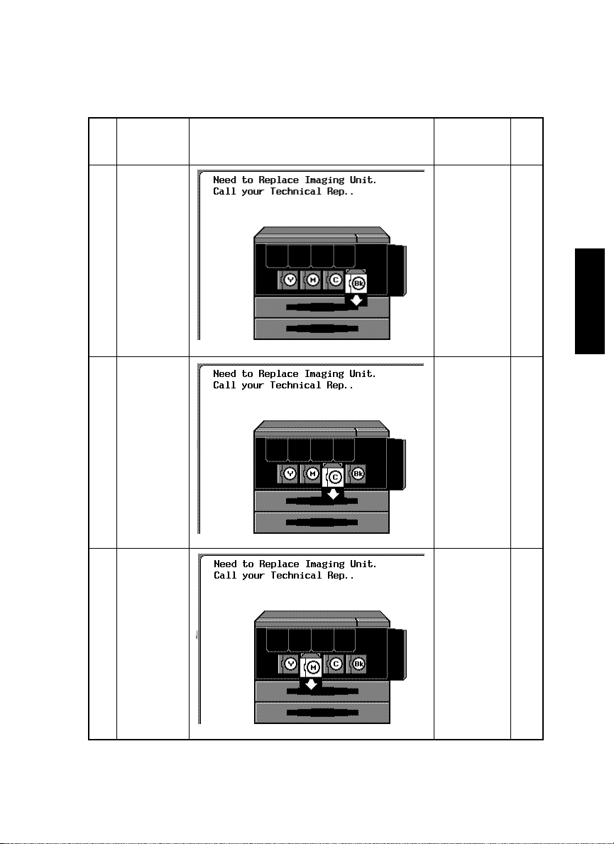
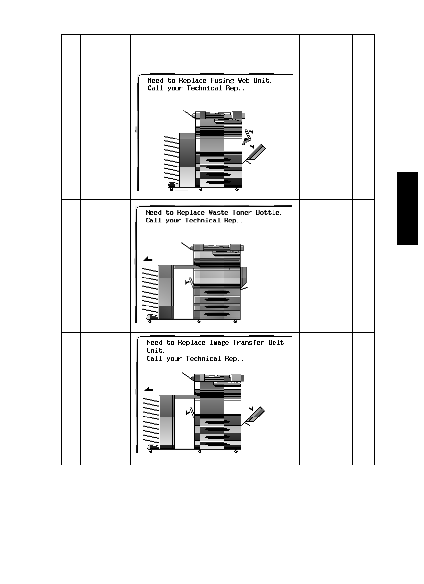
No. Unit Name Maintenance Message Display
Imaging Unit
1.
(Bk)
Imaging Unit
2.
(C)
PM Cycle
CF2001/
CF1501
7122 min
(51K/48K)
4562 min
(31K/28K)
Page
No.
P-21
P-11
Imaging Unit
3.
(M)
1
4562 min
(31K/28K)
P-11
No. Unit Name Maintenance Message Display
PM Cycle
CF2001/
CF1501
Page
No.
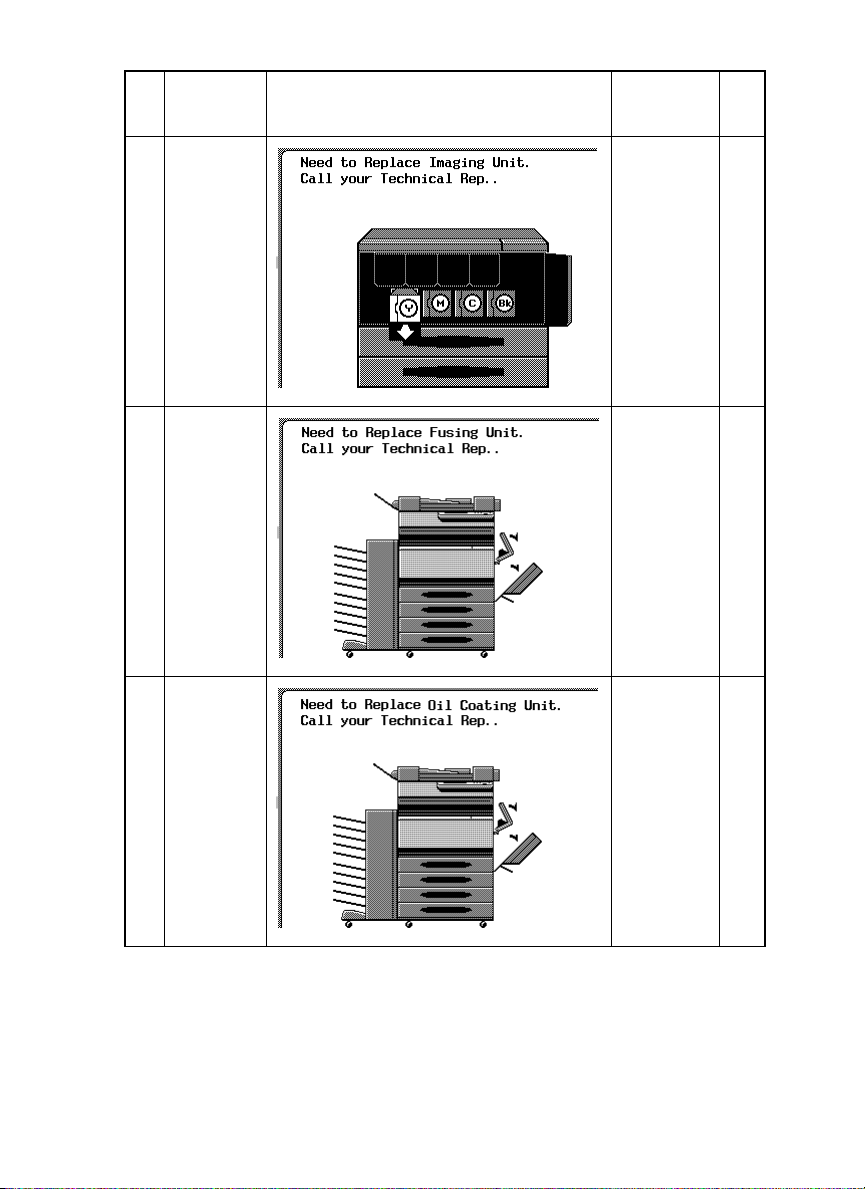
Imaging Unit
4.
(Y)
5. Fusing Unit 102K/102K P-22
Oil Coating
6.
Unit
4562 min
(31K/28K)
34K/27K P-6
P-11
2
No. Unit Name Maintenance Message Display
PM Cycle
CF2001/
CF1501
Page
No.
Fusing Web
7.
Unit
Waste Toner
8.
Bottle
Image
9.
Transfer Belt
Unit
17K/17K P-2
40K/40K P-19
17545 min
(121K/121K)
P-26
3

No. Unit Name Maintenance Message Display
Image
10.
Transfer
Roller Unit
Paper Dust
11.
Cleaner
12. Ozone Filter Nothing to indicate 121K/121K P-26
Nothing to indicate 121K/121K P-26
Nothing to indicate 121K/121K P-26
PM Cycle
CF2001/
CF1501
Page
No.
4
3. Unit Replacement Manual
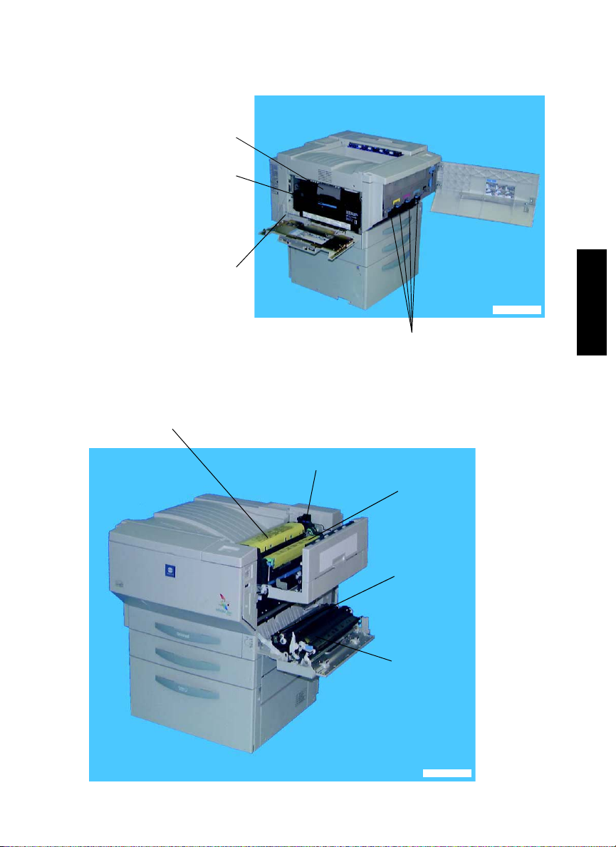
3-1. Unit Layout
Image Transfer Belt Unit
Replace every 121 K.
Replace the waste toner
bottle about 4.5 K prints
after WASTE TONER
BOTTLE NEARLY FULL
is detected.
Ozone Filter
Replace every 121 K.
Fusing Web Unit
Replace the web unit every 17 K prints,
or about 1 K prints after WEB UNIT
NEARLY EMPTY is detected.
Fusing Unit
Replace every 102 K.
4004D301AA
Imaging Unit
C, M, Y: Replace every 4,562 M.
Bk: Replace every 7,204 M.
Oil Coating Unit
Replace every 34 K or
325,000 sec.
1
Paper Dust Remover
Replace every 121 K.
Image Transfer Roller Unit
Replace every 121 K.
4004D302AA
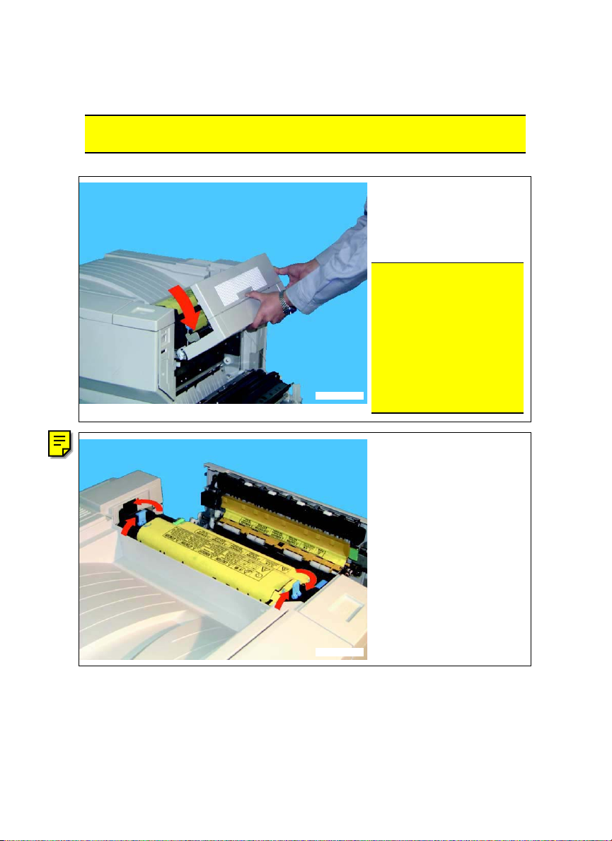
3-2. Replacing the Units
(1) Replacing the Fusing Web Unit
Removal method
NOTE
• Before replacing the fusing web unit, ensure that it is not hot.
1. Turn OFF the main switch,
2. Open the Upper Right
NOTE
• When opening the upper
4004D352CA
3. Release the two blue lock
➁
then wait for about 20 minutes.
Door.
right door, be sure to support it with your hand until it
is in the fully open position.
If you remove your hand
from the upper right door, it
may drop, and the resulting
impact may cause the
hinges to bend.
levers.
➀
(
: Push up, ➁: Rotate)
➀
➁
➀
4004D264AA
2
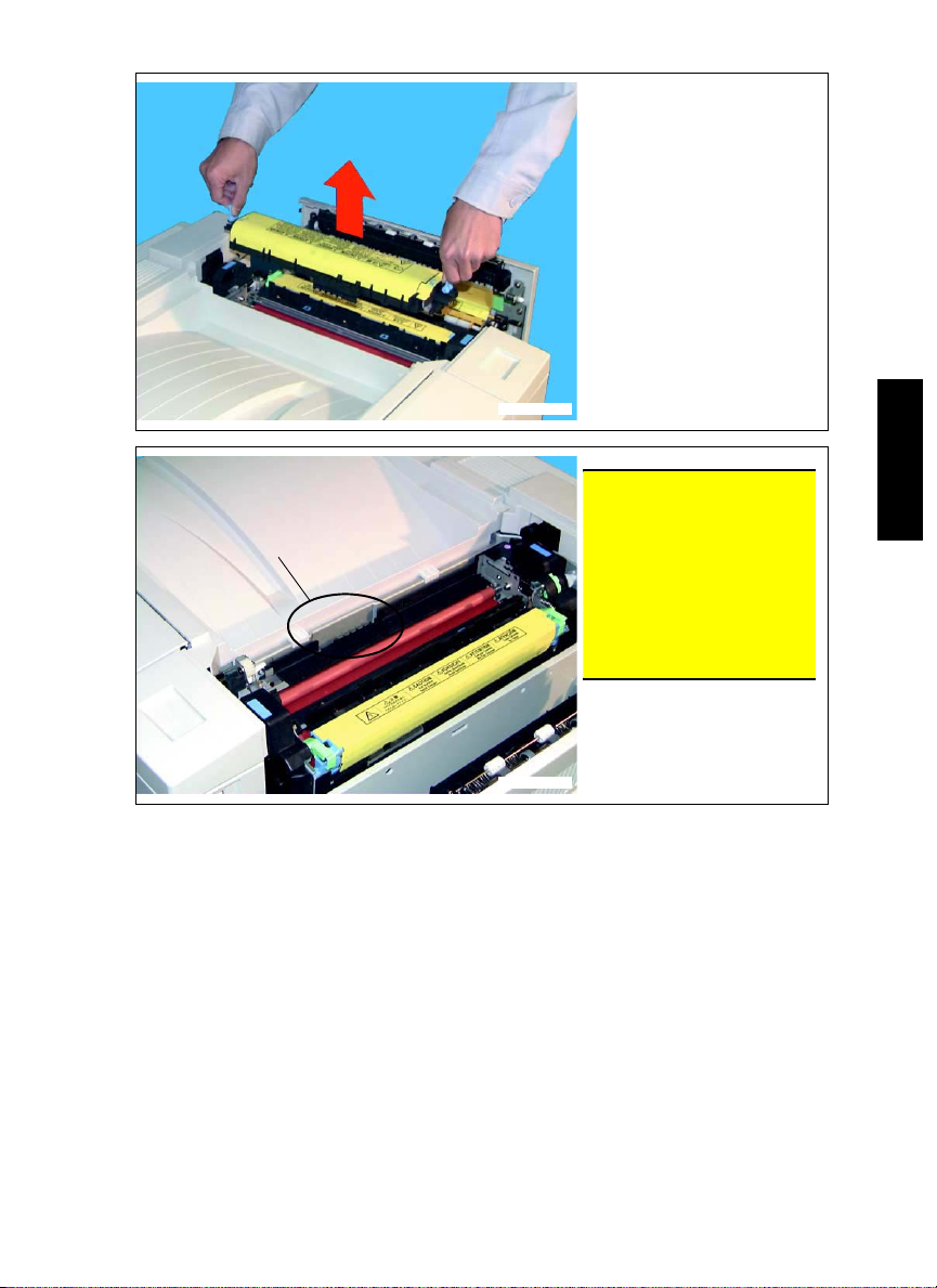
Terminals (metal)
4. Grasp the two blue lock
levers, and remove the
fusing web unit.
4004D306AA
NOTE
• Do not touch the metal ter-
minals beneath the fusing
web unit (on the fusing unit
side).
Failure to observe this precaution may cause an electrostatic discharge, resulting
in a breakdown.
3
4004D307AA
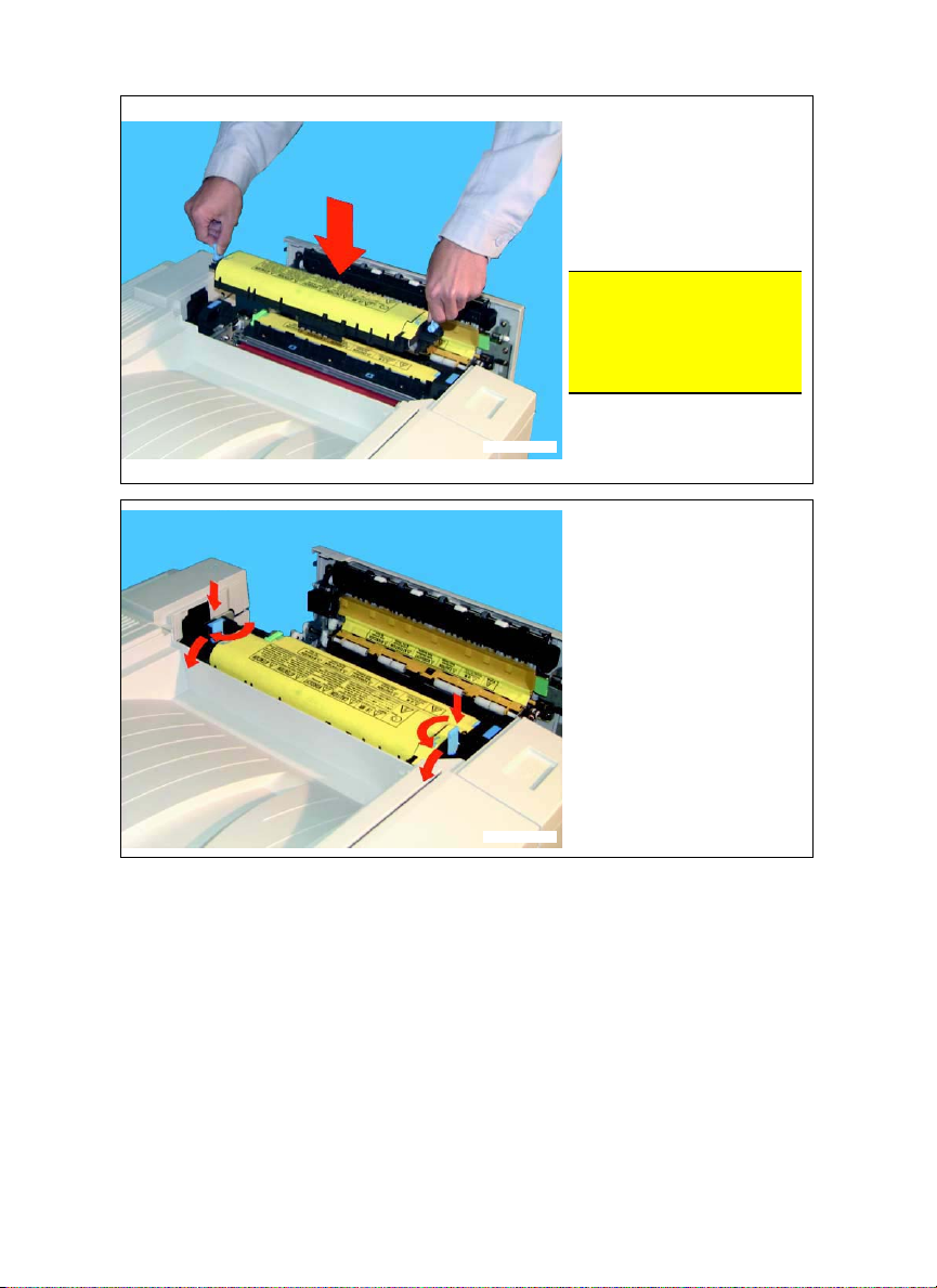
Installation method
➀
➁
➂
➁
➀
4004D308AA
1. Remove the fusing web
unit from its box, and
remove the packing material.
2. Grasp the two blue lock
levers, and set the fusing
web unit in place.
NOTE
• When setting the fusing web
unit, align the
the fusing web unit with the
▼
mark on the fusing unit.
3. Lock the two blue lock
levers.
➀
: Push, ➁: Rotate,
(
➂
: Push down)
▼
mark on
➂
4004D265AA
4
 Loading...