

Page 1

Display Color Analyzer
CA-310
INSTRUCTION MANUAL
Page 2
Safety Symbols
The following symbols are used in this manual to prevent accidents which may occur as result of incorrect
use of the instrument.
Denotes a sentence regarding safety warning or note.
Read the sentence carefully to ensure safe and correct use.
Denotes a sentence regarding safety precautions for risk of fire.
Read the sentence carefully to ensure safe and correct use.
Denotes a sentence regarding safety precautions for risk of electric shock.
Read the sentence carefully to ensure safe and correct use.
Denotes a prohibited operation.
The operation must never been performed.
Denotes an instruction.
The instruction must be strictly adhered to.
Denotes an instruction.
Disconnect the AC power cord from the AC outlet.
Denotes a prohibited operation.
The part must never be disassembled.
Denotes an instruction.
Connect the grounding terminal as instructed.
SIP/SOP Connections
• Accessories equipment connected the analog and digital interfaces must be certified to the respective
IEC standards (i.e. IEC 60950 for data processing equipment).
• Furthermore all configurations shall comply with the system standard IEC 61010-1. Everybody who
connects additional equipment to the signal input part or signal output part configures a electrical equipment for measurement system, and is therefore, responsible that the system complies with the requirements of the system standard (IEC 61010-1. If in doubt, consult the technical services department or your
local representative).
Notes on this Manual
• Copying or reproduction of all or any part of the contents of this manual without KONICA MlNOLTA’s
permission is strictly prohibited.
• The contents of this manual are subject to change without prior notice.
• Every effort has been made in the preparation of this manual to ensure the accuracy of its contents.
However, should you have any questions or find any errors, please contact a Konica Minolta authorized
service facility.
• KONICA MINOLTA will not accept any responsibility for consequences arising from the use of the
instrument.
Page 3
Safety Precautions
When using this hardware, the following points must be strictly observed to ensure correct and safe use.
After you have read this manual, keep it in a safe place so that it can be referred to easily whenever it is needed.
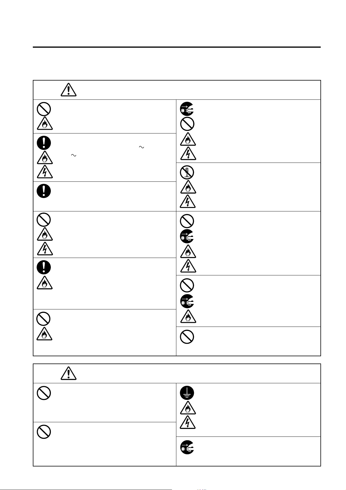
WARNING
Do not use the CA-Series in places where flam-
mable or combustible gases (gasoline etc.) are
present. Doing so may cause a fire.
Always use the AC power cord supplied as a
standard accessory (for 100-120V or for 200-
240V ) with the CA-Series, and connect it to
an AC outlet . Failure to do so may damage the
CA-Series, causing a fire or electric shock.
Securely insert the power plug as far as it will go.
If the plug is not fully inserted, fire or electric
shock may result.
Do not bend, twist or pull the AC power cord ex-
cessively. In addition, do not place heavy items
on the AC power cord, or damage or modify it in
any way. Doing so may cause damage to the AC
power cord, resulting in fire or electric shock.
If the CA-Series will not be used for a long time,
disconnect the AC power cord from the AC out-
let. Accumulated dirt or water on the prongs of
the AC power cord’s plug may cause a fire. If there
is any dirt or water on the prongs of the AC power
cord’s plug, remove it.
The CA-Series should not be operated if dirt or
dust has entered through the vent holes. Doing so
may result in a fire. For periodic inspection, con-
tact the nearest Konica Minolta authorized service
facility.
(Failure to adhere to the following points may result in death or
serious injury.)
When disconnecting the AC power cord’s plug,
always hold the plug and pull it to remove it. Never
pull the AC power cord itself. Doing so may dam-
age the AC power cord, causing a fire or electric
shock. In addition, do not insert or disconnect the
AC power cord’s plug with wet hands. Doing so
may cause electric shock.
Do not disassemble or modify the CA-Series. Do-
ing so may cause a fire or electric shock.
Take special care not to allow liquid or metal ob-
jects to enter the CA-Series. Doing so may cause a
fire or electric shock. Should liquid or metal ob-
jects enter the CA-Series, turn the power OFF im-
mediately, disconnect the AC power cord from the
AC outlet, and contact the nearest Konica Minolta
authorized service facility.
The CA-Series should not be operated if it is dam-
aged, or smoke or odd smells are detected. Doing
so may result in a fire. In such situations, turn the
power OFF immediately, disconnect the AC power
cord from the AC outlet, and contact the nearest
Konica Minolta authorized service facility.
Take care not to drop or overturn the CA-Series.
Failure to adhere to this precaution may result in
injury or your body being trapped.
Explanation Section
CAUTION
Do not place the instrument on an unstable or slop-
ing surface. Doing so may result in its dropping
or overturning, causing injury. Take care not to
drop the instrument when carrying it.
Do not block the vent. Doing so may cause fire.
(Failure to adhere to the following points may result in injury or
damage to the instrument or other property.)
Be sure to connect the AC power cord’s plug to an
AC outlet that has a protective grounding termi-
nal. Also make sure that peripheral devices (e.g.
PC) are connected to AC outlets that have a pro-
tective grounding terminal. Failure to do so may
result in electric shocks.
Unplug the power cord from the outlet before ser-
vicing the instrument. Failure to do so may cause
electric shock.
1
Page 4

Foreword
Thank you for purchasing the Display Color Analyzer CA-310. This instrument is designed for measurement of
color, and lumminance of various types of color displays with LED Universal Measuring Probe or color, lumminance
and flicker of color LCD displays with LED Flicker Measruing Probe. Before using this instrument, please read
this manual thoroughly.
Notes on Use
● This instrument is designed for indoor use only, and should not be used outside.
● The instrument must never be disassembled as it is composed of precision electric components.
● Always use the rated power voltage. Connect the AC power cord (for 100-120 V or for 200-240 V) to an AC
outlet. Make sure that main supply voltage fluctuates up to ±10 % of the nominal voltage.
● This instrument is classified as Pollution Degree 2(equipment which may cause temporary electrical hazards
due to contamination or condensation, or products which are used in such an environment).
● Do not use the instrument at altitudes of higher than 2000 m.
● The instrument must not be used if foreign matter such as water and metal objects enter it, doing so is very
dangerous.
● The instrument should not be used in certain environments, such as near a heater which will cause an excessive
rise in its temperature resulting in breakdown. Therefore it should not be used in such an environment. It should
be used in well-ventilated areas, and care should be taken not to allow the vent holes to become blocked.
● The instrument must not be used in areas subject to rapid changes of temperature, to avoid condensation.
● The instrument must not be used in areas where there is an excessive amount of dust or where the humidity is
excessively high.
● The instrument should be used at ambient temperatures of between 10 and 28˚C and humidity of 70 % relative
humidity or less. Be aware that to use it beyond this condition may make it degrade the performance.
● The instrument must not be exposed to excessive impact and vibrations.
● The AC power cord must not be pulled or bent excessively nor must excessive force be exerted on it. Doing so
may result in wire breakage.
● The AC power cord must not be connected to an AC line on which excessive noise is present.
● The instrument and personal computer must be grounded.
● If any irregularity or abnormality is found, turn OFF the power immediately, disconnect the AC power cord,
and refer to “Troubleshooting Guide” on page 107.
● Should the instrument break down, do not try to disassemble by yourself. Contact a Konica Minolta authorized
service facility.
● Zero Calibration shall be made only after duration of 30 minutes or more passed since the power supply switch
is turned ON if the luminance of the display to be measured is the following.
●
1.0 cd/m2 or less for LED Universal Measuring φ27 Probe (CA-PU32, CA-PU35) / LED Flicker Measuring
φ27 Probe (CA-P32, CA-P35)
●
3.0 cd/m2 or less for LED Universal Measuring φ10 Probe (CA-PSU32, CA-PSU35) / LED Flicker Measuring φ10 Probe (CA-PS32, CA-PS35)
2
Page 5
Notes on Storage
● The instrument should be stored at temperatures of between 0 and 28˚C (70 % relative humidity or less and no
condensation) or at temperatures of between 28 and 40˚C (40 % relative humidity or less and no condensation).
It is recommended that the instrument be stored at room temperature and humidity. Storing the instrument at a
higher temperature and humidity may dateriorate the performance of the instrument.
● Take care not to allow condensation to form on the instrument during storage. In addition, pay attention to rapid
temperature changes during transportation to the storage area to prevent condensation.
Cleaning
● If the instrument gets dirty, wipe it with a soft dry cloth. Never use solvents (e.g. benzene, thinner) or other
chemicals.
● If the optics of the probe gets dirty, wipe it with a soft dry cloth or lens cleaning paper.
● If it is not possible to remove dirt from the instrument, contact a Konica Minolta authorized service facility.
Notes on transfer
● Use packaging material supplied when purchased to minimize vibration or shock generated during transfer.
● Put all material including unit and accessories in original packaging material when returning this instrument
for service.
Maintenance
● Periodical checkup is recommended annually to maintain measurement accuracy of instrument. For details on
checkup, please contact the nearest KONICA MINOLTA SENSING authorized service facility.
Disposal Method
● Please dispose of this product according to the rules and regulations of the governing body of the respective
region.
● Contains Mercury in the backlighting of LCD used for display, Dispose According to Local, State or Federal
Laws.
About This Manual
This manual is designed for those who possess basic knowledge of LCD displays.
Before using this instrument, please read this manual thoroughly.
In some parts of the description about LED Universal Measuring φ27 Probe, LED Universal Measuring φ10Probe,
LED Flicker Measuring φ27 Probe and LED Flicker Measuring φ10 Probe on this manual where type of probe is
not specified, they are described as "Measuring Probe".
A quick summary of measurement methods is given in “Measurement/Quick Guide” (pages 114to 118), please
refer to it when you need a quick check.
Explanation Section
For Those Who Want to Purchase Optional Accessories for this Instrument
This manual also explains how to use optional accessories available for this instrument.
If an explanation of how to use an optional accessory is given in this manual, its product name is also given.
Please read the explanation together with the manual supplied with the accessory.
<Example> ● Location of the explanation regarding 4-Probe Expansion Board CA-B15
When the optional 4-Probe Expansion Board CA-B15 is used
3
Page 6
Contents
Safety Precautions ........................................................................................................................................................................ 1
Foreword ....................................................................................................................................................................................... 2
Notes on Use ................................................................................................................................................................................. 2
Notes on Storage ........................................................................................................................................................................... 2
Cleaning ........................................................................................................................................................................................ 3
Notes on transfer ........................................................................................................................................................................... 3
Maintenance ................................................................................................................................................................................. 3
Disposal Method ........................................................................................................................................................................... 3
About This Manual ....................................................................................................................................................................... 3
Manual Structure .......................................................................................................................................................................................... 6
Names and Functions of Parts .................................................................................................................................................................... 10
About Accessories ........................................................................................................................................................................................ 13
Standard Accessories .................................................................................................................................................................. 13
Optional Accessories ..................................................................................................................................................................13
About Measuring Probe .............................................................................................................................................................................. 14
Setting a Measuring Probe .......................................................................................................................................................... 14
Setting the Measuring Distance ..................................................................................................................................................14
About Pointing Ring ...................................................................................................................................................................15
Function of Each Key ..................................................................................................................................................................................16
About Display .............................................................................................................................................................................................. 19
Installation/Connection ___________________________________________23
About Installation ........................................................................................................................................................................................25
About Connection ........................................................................................................................................................................................26
1. Connecting a Measuring Probe .............................................................................................................................................. 26
2. Installing the 4-Probe Expansion Board CA-B15
3. Connecting the Power ............................................................................................................................................................. 28
4. Inputting the Vertical Synchronizing Signal ...........................................................................................................................28
Turning the Power ON ( | )/OFF (O) ..........................................................................................................................................................29
1. Turning the Power ON ( | )/OFF (O) ......................................................................................................................................29
2. Instrument Status at Power-ON ..............................................................................................................................................30
3. About the change of Luminance Unit.....................................................................................................................................32
When the optional 4-Probe Expansion Board CA-B15 is used
................ 27
Measurement Preparation _________________________________________33
Zero Calibration .......................................................................................................................................................................................... 34
1. Performing Zero Calibration ..................................................................................................................................................34
2. Zero Calibration Check Method .............................................................................................................................................35
Selecting, Measovement Speed, SYNC Mode, Display Mode
and the Number of Display Digits ..............................................................................................................................................................36
1. Selecting the Measurement Speed ..........................................................................................................................................36
2. Selecting SYNC Mode ........................................................................................................................................................... 38
3. Selecting the Measurement Mode .......................................................................................................................................... 40
4. Selecting the Number of Display Digits ................................................................................................................................. 42
Selecting Probe No.
When the optional 4-Probe Expansion Board CA-B15 is used
............................................................................ 43
Settings Section __________________________________________________45
Outline of the Settings Section ................................................................................................................................................................... 46
4
Page 7

Before Making Each Setting ....................................................................................................................................................................... 48
1. About Memory Channels........................................................................................................................................................48
2. About the Target Color ...........................................................................................................................................................49
3. Selecting the Calibration Standard (data) ...............................................................................................................................50
User Calibration ..........................................................................................................................................................................................51
1. About User Calibration ........................................................................................................................................................... 51
2. Performing White Calibration ................................................................................................................................................ 52
3. Performing Matrix Calibration ............................................................................................................................................... 54
Analyzer Mode .............................................................................................................................................................................................58
1. About Analyzer Mode ............................................................................................................................................................. 58
2. Inputting the RGB Emission Characteristic for Analyzer Mode ............................................................................................ 59
Setting/Changing the Target Color ............................................................................................................................................................ 62
1. Setting/Changing the Target Color by Measurement .............................................................................................................63
2. Setting/changing the target color by entering values ..............................................................................................................65
Other Settings ..............................................................................................................................................................................................67
1. Setting an ID Name ................................................................................................................................................................ 67
2. Setting the Analog Display Range..........................................................................................................................................69
Settings Checking Method ..........................................................................................................................................................................73
1. Checking the Set Values .........................................................................................................................................................73
2. Checking the Probe Serial No. when Making Settings ..........................................................................................................74
Measurement Section _____________________________________________75
Measurement ................................................................................................................................................................................................76
1. Performing Measurement ....................................................................................................................................................... 76
2. Holding the Measured Values .................................................................................................................................................77
3. Displaying the Measured Values ............................................................................................................................................ 78
White Balance Adjustment in Analyzer Mode ..........................................................................................................................................81
Communications Section __________________________________________85
Communicating with PC ............................................................................................................................................................................. 86
1. Communicating with PC via RS-232C ................................................................................................................................... 86
2. Selecting the RS-232C Baud Rate .......................................................................................................................................... 87
3. Communicating with PC via USB .......................................................................................................................................... 88
4. Remote Measurement .............................................................................................................................................................88
Explanation Section ______________________________________________89
Measuring Principle .................................................................................................................................................................................... 90
1. Measuring Principle ................................................................................................................................................................ 90
2. About T∆uvLv ........................................................................................................................................................................ 91
3. Principle of User Calibration ..................................................................................................................................................92
4. Principle of Analyzer Mode....................................................................................................................................................93
5. Optical System of Measuring Probe .......................................................................................................................................94
6. Principle of Flicker Mode ....................................................................................................................................................... 96
Maintenance ...............................................................................................................................................................................................101
1. Cleaning the Instrument ....................................................................................................................................................... 101
2. Storing the Instrument .......................................................................................................................................................... 101
Dimension Diagram ................................................................................................................................................................................... 102
Error Messages .......................................................................................................................................................................................... 103
Troubleshooting Guide ..............................................................................................................................................................................107
Specifications ............................................................................................................................................................................................. 110
Measurement/Quick Guide....................................................................................................................................................................... 114
5
Page 8
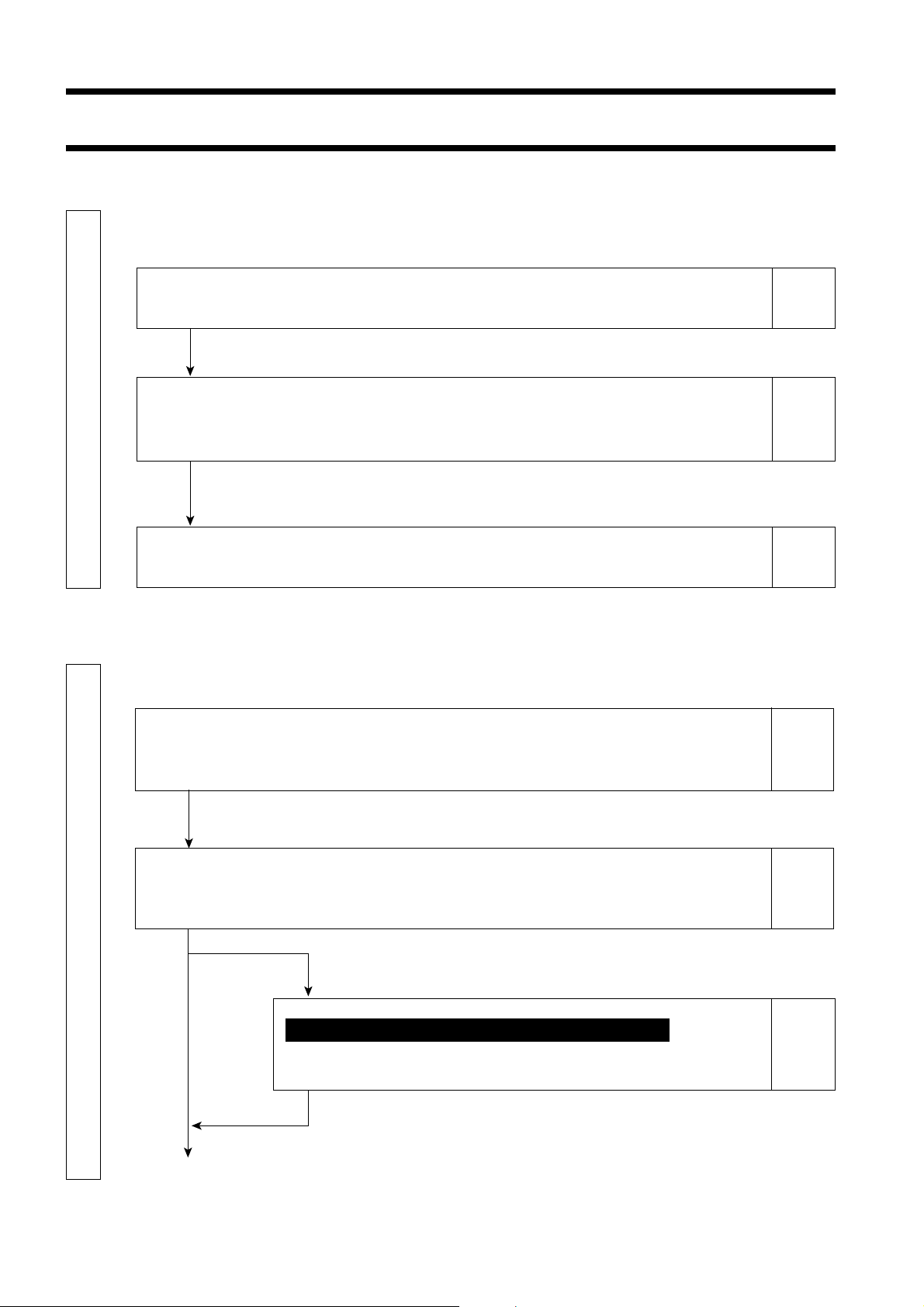
Manual Structure
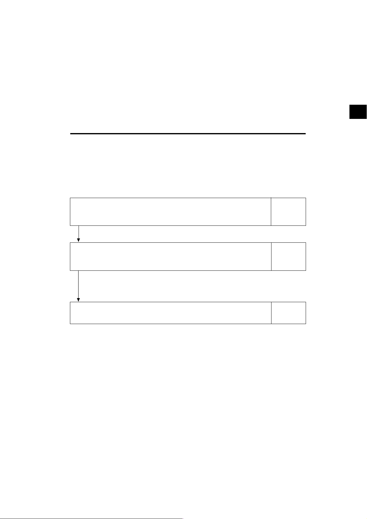
This manual is divided into sections as shown below according to the contents.
This section explains how to install the instrument, connect AC power, turn ON/OFF the power, and
input the vertical synchronizing signal.
About Installation
Provides operating environmental conditions for the instrument and notes on installation.
About Connection
Explains how to connect measuring probes and connect the power cord.
(Also explains installation method for the optional accessory “4-Probe Expansion Board”.)
* Before turning on the power: Refer to pages 86 to 88 if you are going to communicate the instru-
ment with the PC via RS-232C or USB.
Installation/Connection P. 23-32
Turning the Power ON/OFF
Explains how to turn ON/OFF the power.
● The Preparation/Setting/Measurement section explains the procedure up to measurement.
The Measurement Preparation section explains preparations (instrument setting, zero calibration) that
are required prior to measurement.
Zero Calibration
Explains the zero point adjustment method.
(Measurement cannot be performed if zero calibration is not completed.)
Page 25
Page 26
Page 29
Page 34
Selecting, Masurement Speed, SYNC Mode, Display Mode and the Number of Display Digits
Explains how to select SYNC mode, that selects measurement time according to the display’s vertical scanning frequency,
as well as explaining how to select measurement mode and the number of display digits.
Measurement Preparation P. 33-44
To the Setting section P. 45-74
When the optional 4-Probe Expansion Board CA-B15 is used
Selecting Probe No.
Explains how to select the measuring probe whose measured value is to be displayed.
* Go to the Measurement section if you are going to perform measurement using
Konica Minolta’s calibration standard and are not going to use analog display.
6
Page 36
Page 43
Page 9
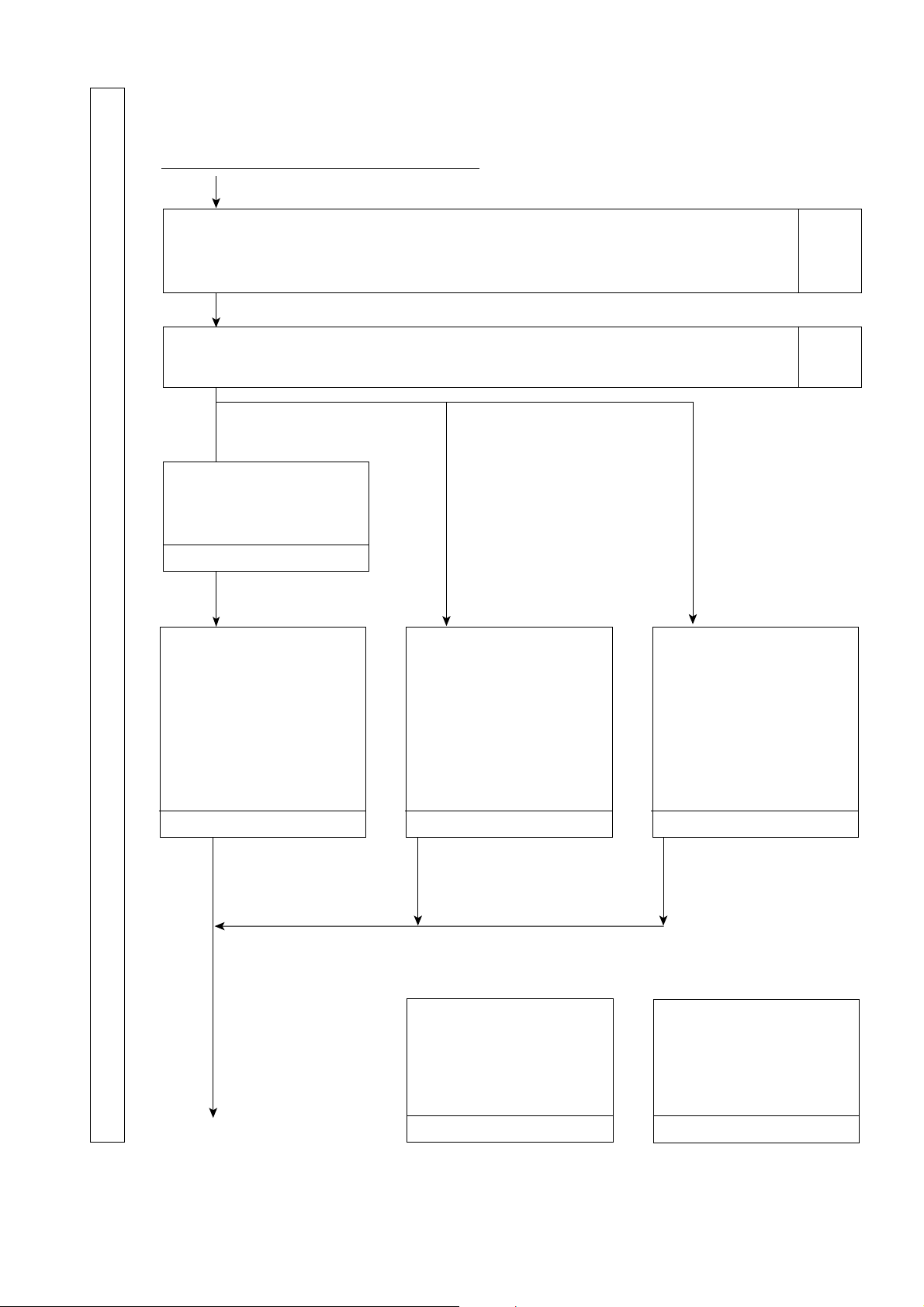
This section explains settings that must be made according to measurement method.
The setting method varies with measurement method.
From the Measurement Preparation section
Outline of the Settings Section
Explains measurement method types and settings that must be made.
(Check what settings you need to make.)
Page 46
Settings Section P. 45-74
Before Making Each Setting
Gives detailed explanations on memory channels common to each setting and target colors.
When performing measurement using
Konica Minolta’s calibration standard
Selecting the Calibration Standard
Select calibration data.
Select 6500K and 9300K.
P. 50
Setting/Changing the Target Color *1
Explains how to set/change the tar-
get color.
1. Setting/Changing the Target
Color by Measurement
2. Setting/Changing the Target
Color by Entering Values
When performing measurement using
user calibration
User Calibration
Gives detailed explanation of user
calibration and explains its execution
method.
(Target color is also set at this time.)
Page 48
When performing measurement in analyzer mode
Analyzer Mode
Gives detailed explanation of ana-
lyzer mode and explains how to input the display’s RGB emission char-
acteristic for Analyzer Mode.
(Target color is also set at this time.)
P. 62 P. 51 P. 58
•To set an ID name:
“Setting an ID Name”
(Page 67) *2
•To use the analog display
function:
“Setting the Analog
Display Range” (Page
69) *3
To the Measurement section
P. 75-84
•To change the target color after user
calibration:
“Setting/Changing the Target Color”
(Page 62) *1
Other Settings
Explains how to set an ID name *2
and analog display range *3.
P. 67 P. 73
7
•To change the target color
after inputting the display’s
RGB emission characteristic:
“Setting/Changing the Target
Color” (Page 62) *1
Settings Checking Method
Explains how to check the set values
and check the probe serial no. used
when the values are set.
Page 10
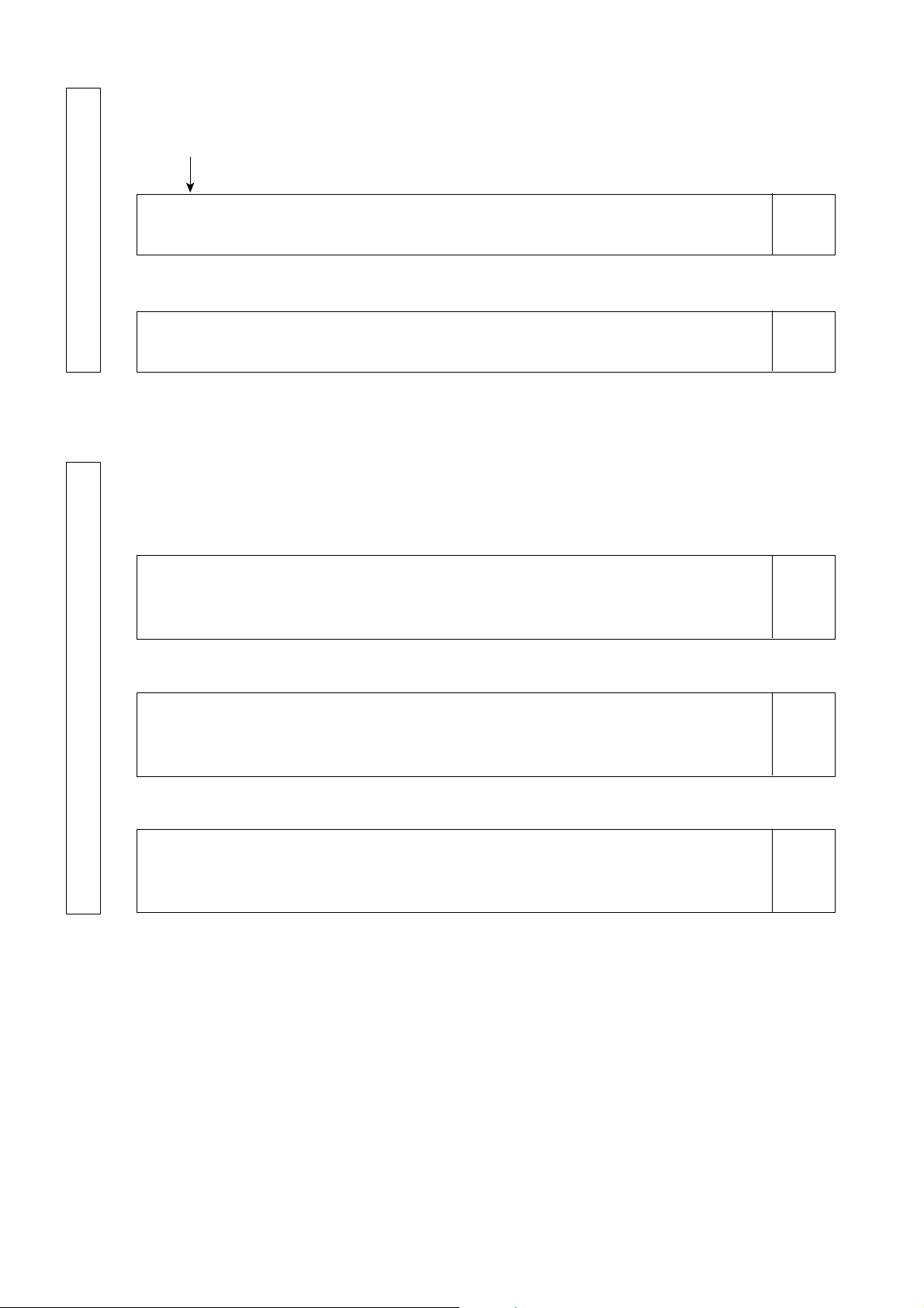
This section explains measuring methods.
From the Settings section
Measurement Section P. 75-84
Measurement
Explains measuring methods, how to hold the measured values and how to read them.
White Balance Adjustment in Analyzer Mode
Explains how to adjust white balance.
This section explains communication with PC via RS-232C or USB.
Communicating with PC via RS-232C
Explains how to connect the RS-232C cable and select the RS-232C baud rate to enable two-way communication with PC
via RS-232C.
Page 76
Page 81
Page 86
Communications Section P. 85-88
Communicating with PC via USB
Explains how to connect the USB cable to enable communication with PC via USB.
Remote Measurement
Explains how to perform measurement from the PC remotely.
Page 88
Page 88
8
Page 11
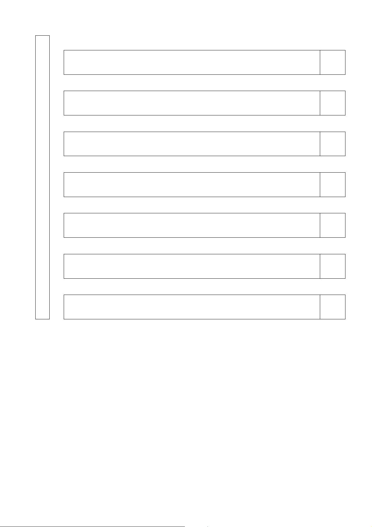
This section explains the following items.
Explanation Section P. 89-118
Measuring Principle
Maintenance
Dimension Diagram
Error Messages
Please read when an error message appears in the LCD display section.
Troubleshooting Guide
Please read when the instrument does not function correctly.
Page 90
Page 101
Page 102
Page 103
Page 107
Specifications
Measurement/Quick Guide
Provides an outline of operations explained in the previous sections (Measurement Preparation - Measurement).
Page 110
Page 114
Explanation Section
9
Page 12
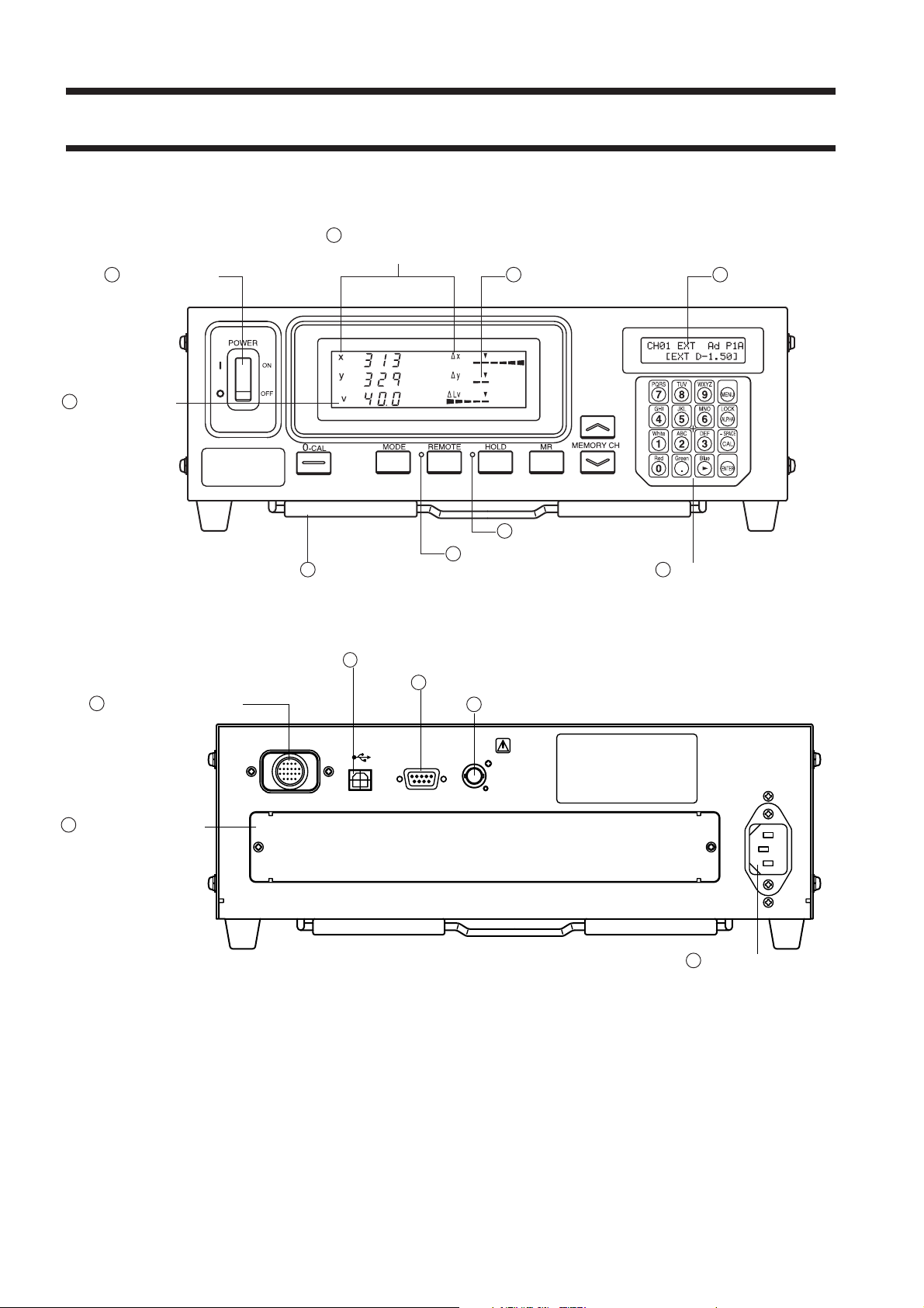
Names and Functions of Parts
Main Body
<Front>
4Measurement mode
indications
1 POWER switch
2 Digital display
6 HOLD LED
7 REMOTE LED
9 Tilt stand
5 LCD display3 Analog display
8 Key panel
<Rear>
10
Probe connector [P1]
15
4-Probe Expansion
Board slot
11
USB connector
12
RS-232C connector
13
Vertical synchronizing signal input terminal
14
AC power connector
10
Page 13
Main Body
<Front>
1 POWER switch........................................ • Used to turn ON and OFF the power to the instrument. (Page 29)
2 Digital display section ............................. • Displays the measured values.
3 Analog display section ............................ • Displays the difference (%) between the measured value and the
target color or the difference (%) between measured values.
Measured values are displayed in the case of flicker mode.
• The range for each dot can be set between 0.1 and 99%. (Page 69)
4 Measurement mode indications ............... • Displays the measurement mode in which the measured values
are displayed. (Page 40)
• The table below shows the relationship between measurement
modes and data displayed in the digital display section 2 and
analog display section 3.
Measurement mode
xyLv mode x, y, Lv ∆x, ∆y, ∆Lv
T∆uvLv mode T, ∆uv, Lv ∆x, ∆y, ∆Lv
Analyzer mode (G reference) R, B, G R/G, B/G, ∆G
Analyzer mode (R reference) R, B, G ∆R, B/G, G/R
u'v'Lv mode u', v', Lv ∆x, ∆y, ∆Lv
Flicker mode** Flicker value Flicker value
XYZ mode XYZ ∆x, ∆y, ∆Lv
**Only when LED Flicker Measuring ø27 Probe or LED Flicker Measuring ø10 Probe is connected.
2
Digital display
3
Analog display
Chapter_Title
5 LCD display ............................................ • Displays the memory channel, probe no., ID name, warning and
settings.
6 HOLD LED ............................................. • Lights up during hold.
7 REMOTE LED ........................................ • Lights up when the instrument is ready for communication with
the PC via RS-232C or USB interface.
8 Key panel ................................................. • Used to select/set probe no., SYNC mode, measurement speed,
analog display range and ID name, as well as entering values.
(Page 17)
9 Tilt stand
<Rear>
10
Probe connector [P1] ............................... • Used to connect a measuring probe. (Page 26)
11
USB connector ........................................ • USB interface for communication with the PC. (Page 88)
12
RS-232C connector ................................. • RS-232C compatible interface for communication with the PC.
(Page 86)
13
Vertical synchronizing signal .................. • Input the display’s vertical synchronizing signal into this terminal
input terminal when performing measurement in EXT SYNC mode. (Page 28)
SYNC: Terminal shall tread as class 3 accordance with IEC
610101-1 Annex-H.
14
AC power connector ................................. • Connect the AC power cord to this connector to supply power to
the instrument. (Page 28)
• The rating is 100-240V
15
4-Probe Expansion Board slot ................. • Used to install the optional 4-Probe Expansion Board (CA-B15).
(Page 27)
, 50-60 Hz, 50VA.
11
Page 14
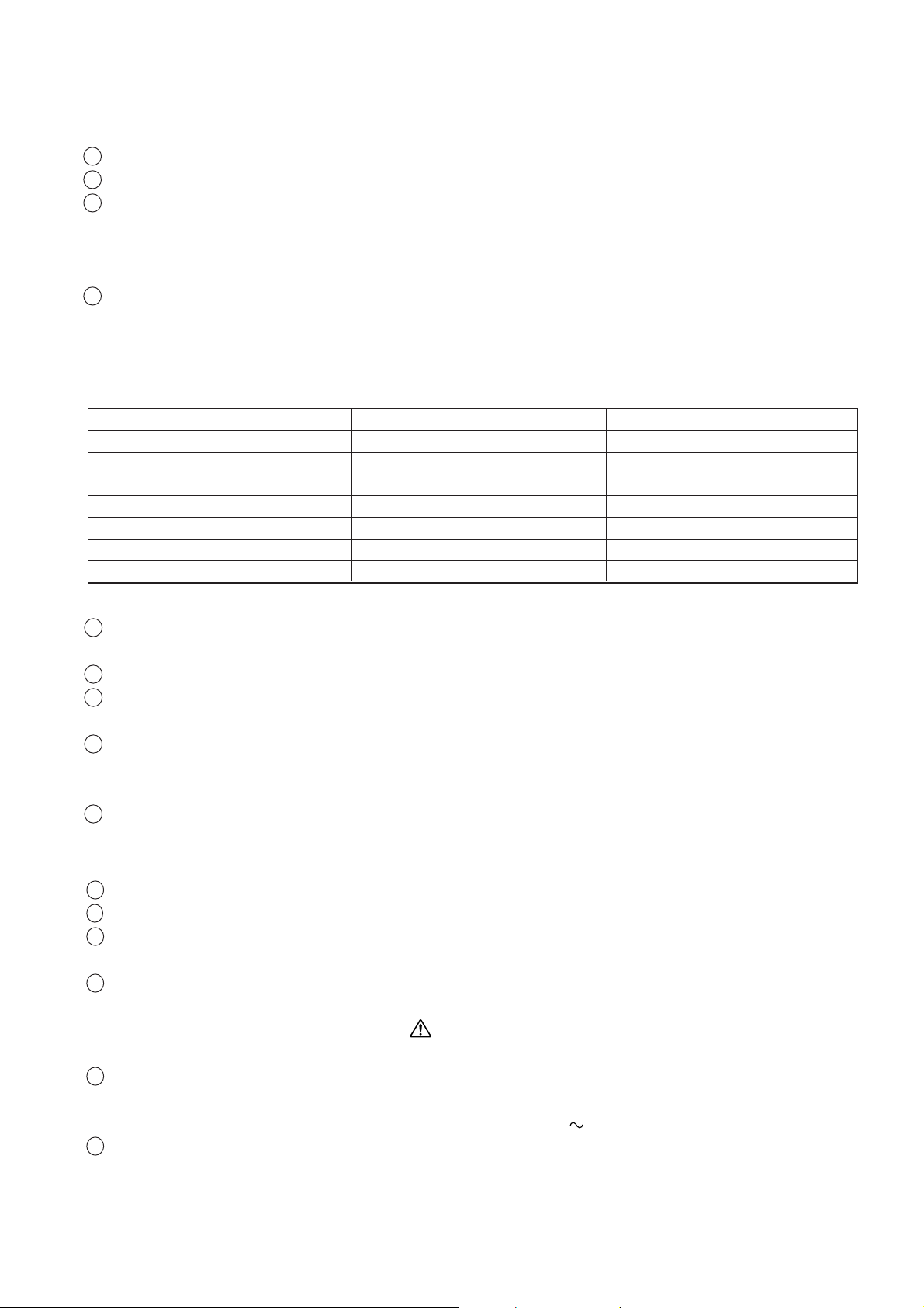
LED Universal Measuring ø27 Probe CA-PU32(2m) /CA-PU35(5m)
LED Universal Measuring ø10 Probe CA-PSU32(2m) /CA-PSU35(5m)
LED Flicker Measuring ø27 Probe CA-P32(2m) /CA-P35(5m)
LED Flicker Measuring ø10 Probe CA-PS32(2m) /CA-PS35(5m)
6 Standard Hood for CA-210/310 CA-H10/
Small Hood for CA-210/310 CA-HS10
4 Screw hole
2 Pointing ring
1 Receptor
5 Plug
7 Standard Lens cap for CA-210/310 CA-H11/
Small Lens cap for CA-210/310 CA-HS11
3 Ring stopper
Measuring is done with a probe in intimate contact with the surface of display in the measuring part of this equipment. There are 2 m(6.6ft.) and 5 m(16.4ft) long cord. There are 4 types of Measuring Probe.
Probe model Cord length Product name Probe model Cord length Product name
LED Universal Measuring ø27 Probe
LED Universal Measuring ø27 Probe
LED Universal Measuring ø10 Probe
LED Universal Measuring ø10 Probe
2m CA-PU32
5m CA-PU35
2m CA-PSU32
5m CA-PSU35
LED Flicker Measuring ø27 Probe
LED Flicker Measuring ø27 Probe
LED Flicker Measuring ø10 Probe
LED Flicker Measuring ø10 Probe
2m CA-P32
5m CA-P35
2m CA-PS32
5m CA-PS35
∗ Either of the accessories described above is included.
1 Receptor ................................................... • Place this receptor against the display’s screen surface and perform
measurement.
2 Pointing ring ............................................ • For zero calibration, set this ring to the “0–CAL” position to block
entry of light into the probe.
For measurement : Set the ring to the “MEAS” position to perform
measurement.
3 Ring stopper............................................. • Stops the ring at two positions.
4 Screw hole ............................................... • Used to secure the probe to a jig etc.
5 Plug .......................................................... • Connect this plug to the probe connector on the main unit or that
on the optional 4-Probe Expansion board (CA-B15).
6 Hood ........................................................ • Used to prevent entry of ambient light and help you place the probe
at the appropriate distance (30 mm) from the display and perpendicular to it.
7 Lens cap ................................................... • Used to protect the receptor.
1212
Page 15
About Accessories
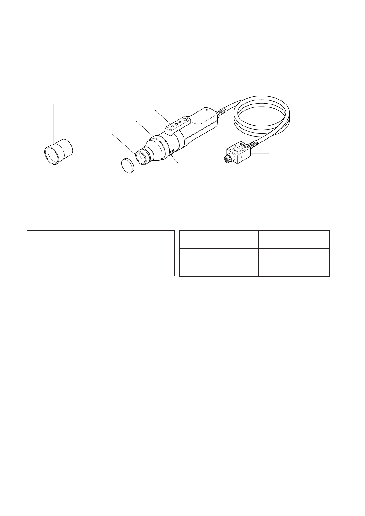
Standard Accessories
● AC power cord (For 100-120V or 200-240 V)
Connect this cord to the AC power connector to supply power to
the instrument.
For a description of how to connect, refer to page 28.
(For 100-120 V)
● Measuring probe(with a lens cap)
● Hood
● Color analyzer PC software CA-SDK
● Instruction manual
Read this manual before operating the instrument.
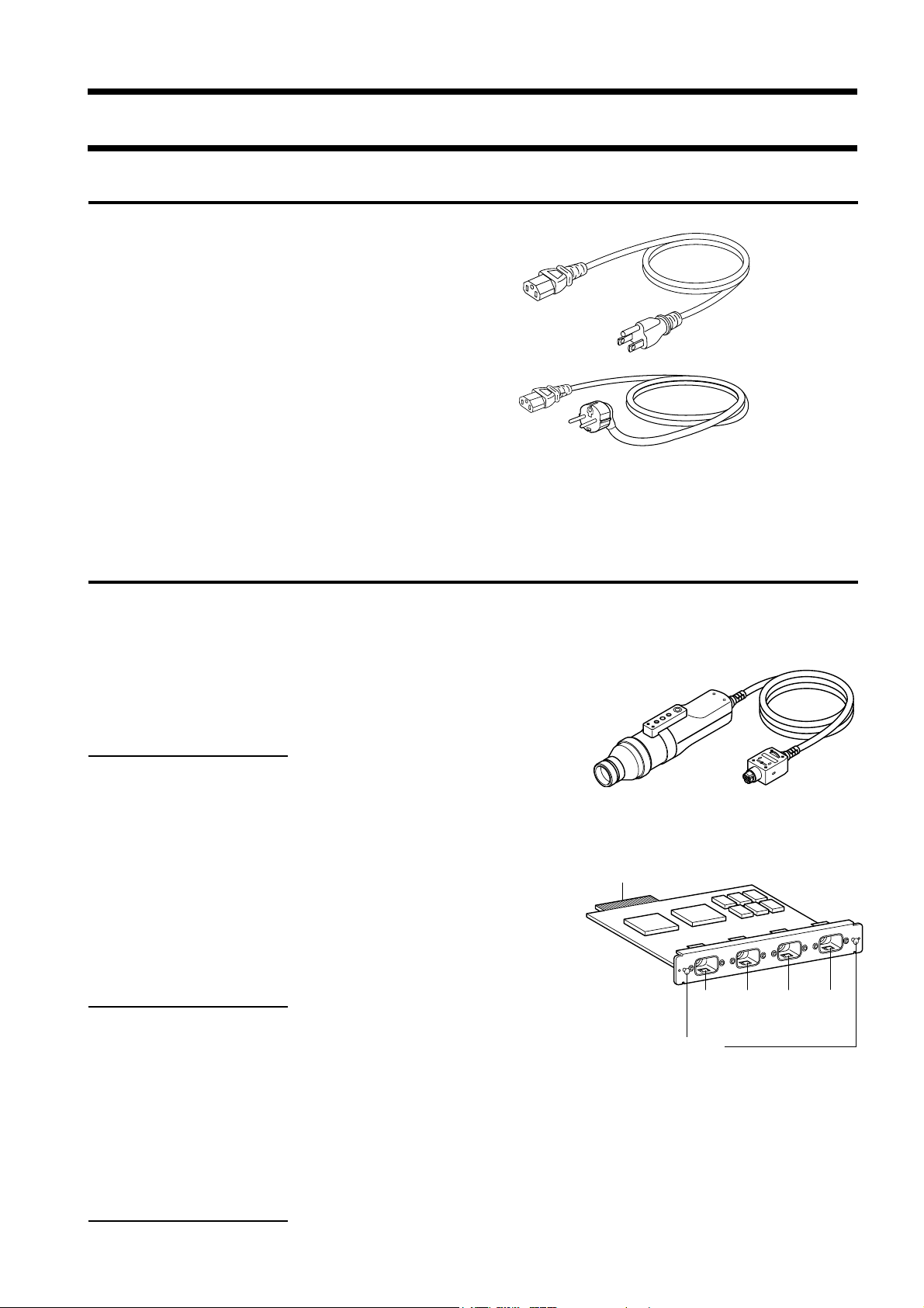
Optional Accessories
● LED Universal Measuring ø27 Probe CA-PU32/CA-PU35
● LED Universal Measuring ø10 Probe CA-PSU32/CA-PSU35
● LED Flicker Measuring ø27 Probe CA-P32/CA-P35
● LED Flicker Measuring ø10 Probe CA-PS32/CA-PS35 (Page 12)
Connect the probes to the main body or the probe connectors on the
4-Probe Expansion Board before measurement.
Location of the explanation
Connecting method: Page 26
Measuring method: Measurement Preparation,
Setting, Measurement sections
(For 200-240 V)
Installation/Connection
● 4-Probe Expansion Board CA-B15
Connect measuring probes to this board, to allow simultaneous
measurement of the colors at up to 5 points on the display’s
surface.It is possible to install Measuring Probes of all types to be
coresident.
Location of the explanation
Installation method: Page 27
Measuring method: Measurement Preparation, Setting, Measure-
ment sections
● Standard Hood for CA-210/310 CA-H10 / Small Hood for CA-210/310 CA-HS10
● Standard Lens cap for CA-210/310 CA-H11 / Small Lens cap for CA-210/310 CA-HS11
● USB cable IF-A18
(Used for communication between this instrument and PC.)
Location of the explanation
Connecting method: Page 86
1313
Connector
[P2]
Grip
[P3]
[P4]
Probe connector
[P5]
Page 16
About Measuring Probe
Setting a Measuring Probe
Two types of screws are provided to secure the measuring prove.
Tripod screw: Used to mount the prove to a tripod. The screw depth is 6 mm.
ISO screw: Used to mount the prove to a jig. An ISO screw (5 mm, depth: 6 mm) can be used.
ISO screw ISO screw
*( )Measuring Ø10 Probe
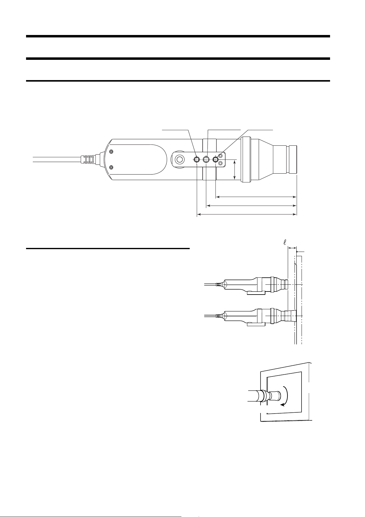
Setting the Measuring Distance
1. Secure the display to be measured.
2. Set the pointing ring to the MEAS position.
3. Make sure that the distance from the dis-
play surface to the tip of the probe is 30
mm, and secure the probe.
Make sure that the probe is placed perpendicular to the
display surface.
Tripod screw
22 mm
88 mm (116)
98 mm (126)
108 mm (136)
(When used without the hood)
(When used with the hood)
=30mm
Display’s
screen
surface
<Caution>
• Measurement reproducibility becomes [the way which does
not change the installation angle θ for every measurement] high in
measuring the high display of view angle dependability with the
Measuring probe.
• Use of the hood (standard accessory) not only prevents entry of environmental light but also makes it easy to place the instrument at the
specified distance and perpendicular to the object.
• LED Universal Measuring ø27 Probe(CA-PU32/35), LED Flicker
Measuring ø27 Probe(CA-P32/35)
: The stated accuracy remains valid when r is in the range of 30 mm
±10 mm.
• LED Universal Measuring ø10 Probe(CA-PSU32/35), LED Flicker
Measuring ø10 Probe(CA-PS32/35)
: The stated accuracy remains valid when r is in the range of 30 mm
±5 mm.
14
Measuring Probe
θ
Display
Page 17
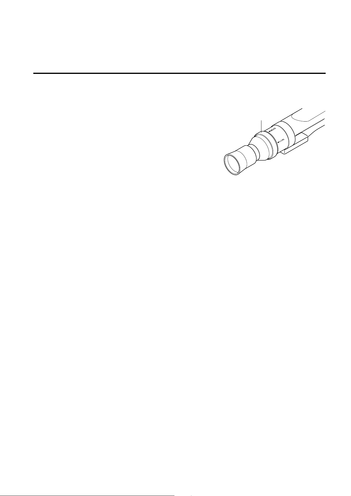
About Pointing Ring
When you turn the pointing ring, it stops at two positions (MEAS, 0-CAL). To turn the ring, the stopper must be
pulled toward you to unlock it.
MEAS : To perform measurement, the ring must be set in this posi-
tion.
0-CAL : To perform zero calibration, the ring must be set in this
position.
Take care not to direct the measuring probe to a high-intensity light source.
Pointing ring
Installation/Connection
15
Page 18
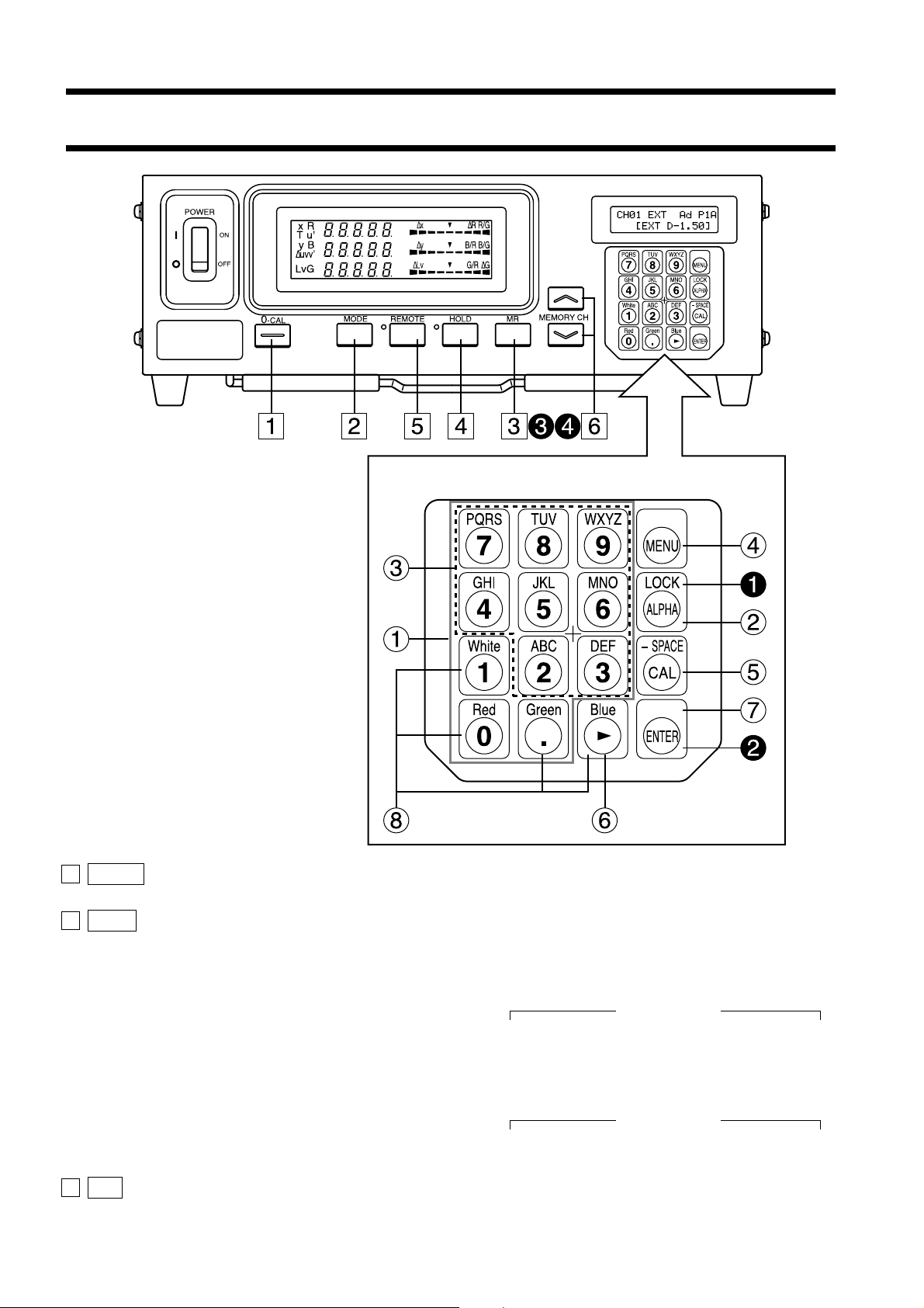
Function of Each Key
Key Panel
1 0-CAL key ............................................. • Performs zero calibration. Before pressing this key, make sure that
the measuring probe is blocked from light. (Page 34)
2 Mode key ............................................... • Select measurement mode. (Page 38)
Measurement mode changes in the following order.
When LED Universal Measuring ø27 Probe(CA-PU32/35) or LED
Universal Measuring ø10 Probe(CA-PSU32/35) is connected,
Analyzer mode
xyLv→T∆uvLv→RBG (R/G, B/G, ∆G)→RBG (∆R, B/G, G/R)→
u'v'Lv→XYZ →xyLv
When LED Flicker Measuring ø27 Probe(CA-P32/35) or LED
Flicker Measuring ø10 Probe(CA-PS32/35) is connected,
Analyzer mode
xyLv→T∆uvLv→RBG (R/G, B/G, ∆G)→RBG (∆R, B/G, G/R)→
u'v'Lv→Flicker**→XYZ →xyLv
3 MR key .................................................. • Displays the specified target color in the LCD display section. (Page
74) (For long depression of this key, refer to page 17.)
16
Page 19
4 HOLD key ............................................. • Holds the display of the measured value. (The HOLD LED will
light up.)
• Pressing this key while the HOLD LED is lit will cancel hold mode.
(The HOLD LED will go out.)
5 REMOTE key ....................................... • Sets the instrument in remote mode (i.e. communication with the
PC is possible via RS-232C or USB).
(The REMOTE LED will light up. See page 88)
• Pressing this key while the REMOTE key is lit will cancel remote
mode. (The REMOTE LED will go out.)
(Note) Remote mode should not be activated unless you are going to communi-
cate with the PC.
Otherwise, the other keys will be inoperative.
6 MEMORY CH key ........................ • Used to select a memory channel (CH00 to 99).
key Pressing the key will switch memory channel in the order
“00→01→02
Pressing the
“00→99→98
…
98→99→00…”.
key will switch memory channel in the order
…
01→00→99…”.
The memory channel switches from one to another each time the
key is pressed, and switches continuously if the key is left held
down.
<Keys on Key Panel>
1 Number-key ( ~ , ) .................. • Used to enter calibration data for user calibration (page 51), target
color (page 62), ID name (page 67) and analog display range (page 69).
2 ALPHA key ( ) ................................... • Used to enter alphabets. This key enables you to use the number-
key as alphabet keys. Pressing this key again will restore the original function of the ten-key.
3 Alphabet keys ( ~ , ) ................ • Used to enter alphabets for the ID name.
Installation/Connection
4 MENU key ( ) ..................................... • Switches the LCD display section to the menu selection screen.
Pressing this key again will restore the original function of the LCD
display section.
5 CAL key ( ) ........................................ Normal Screen
• When CH00 is selected as the memory channel
You can enter a value for the target color. (Page 65)
• When the memory channel other than CH00 is selected as the memory
channel
You can set CA-310 for input of WRGB data for user calibration.
(Page 51)
• When an analyzer measurement mode is selected
You can set CA-310 for input of RGB emission characteristic and
target color (W). (Page 59)
This does not apply in the case of flicker mode**.
Menu Selection Screen
• Pressing the
to switch as follows.
PROBE selection → SYNC selection → ID Name input → RANGE
setting → Measurement Speed selection → Number of Digits setting → Calibration Standard selection→ RS232C Baud Rate selection → PROBE selection
key in the menu selection screen causes the screen
**Flicker Mode is a function which can be used only when LED Flicker Measuring ø27 Probe(CA-P32/35) or LED Flicker Measuring ø10
Probe (CA-PS32/35) is connected.
17
Page 20
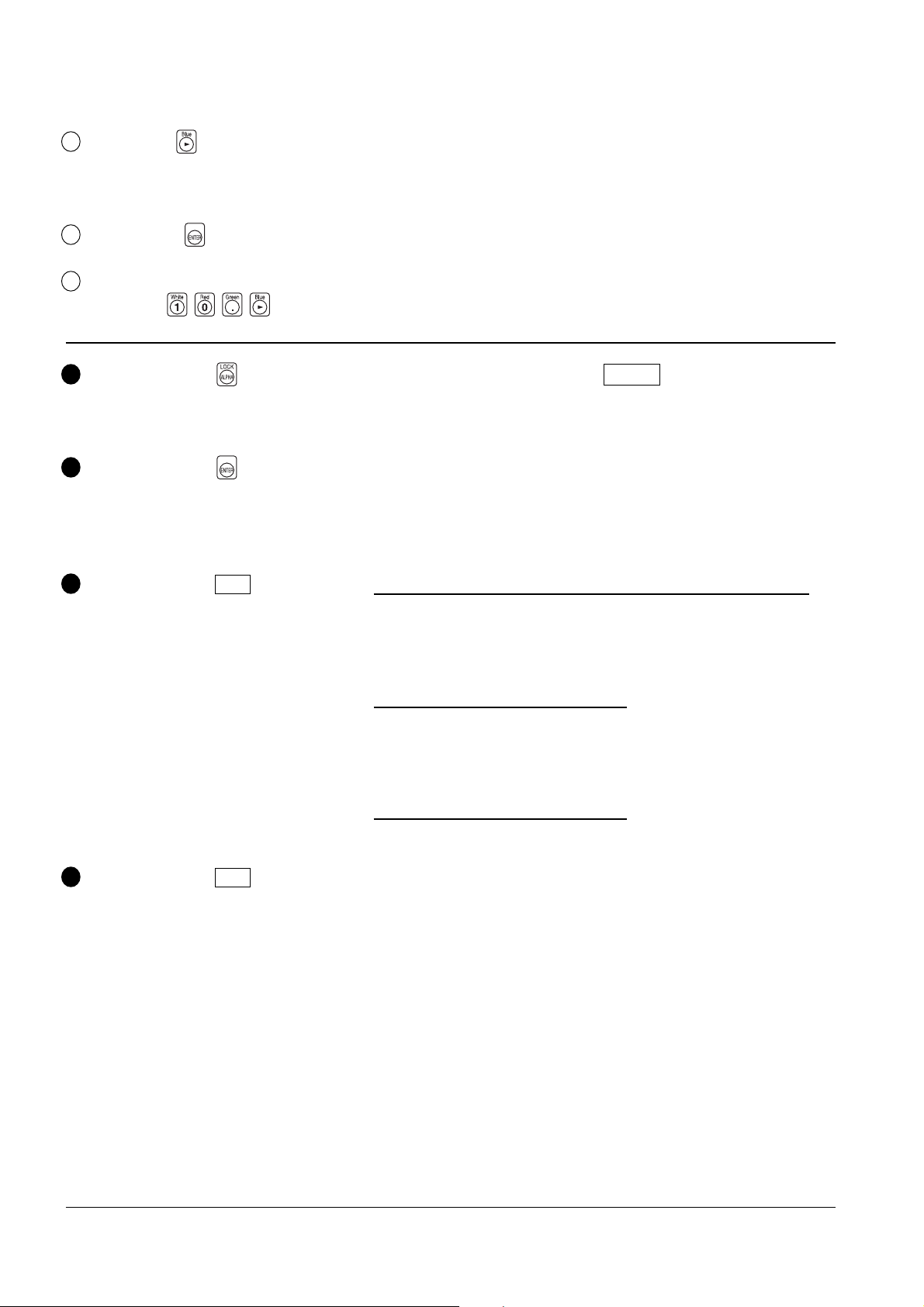
6 Cursor key ( ) ..................................... • Used to switch from one option to another in the PROBE, SYNC,
Measurement Speed, Number of Digits, and RS232C baud rate
screens, which are opened from the menu selection screen.
7 ENTER key ( ) ................................... • Used to confirm each setting/selection you have made.
8 White, Red, Green, .................................. • Used to set RGB emission characteristics of the display.
Blue keys (
)
1 Holding down the key ....................... Locks all the keys except for the 0-CAL key. Holding down this
for two seconds or more key again for two seconds or more will unlock the keys.
(Whistling sound.)
2 Holding down the key .......................
for five seconds or more
(Bleeping sound. A whistling sound
Stores the current settings (probe, SYNC, memory channel, measurement
mode) to the instrument. The settings will be effective when the power
turned on next time.
is heard when the setting is saved.)
3 Holding down the MR key .................... When xyLv, T
∆∆
∆uvLv or XYZ measurement mode is selected
∆∆
for two to four seconds Displays serial number of the probe in use at the time calibration to
(Bleeping sound.) a user selected reference was performed and the target color were
set. (Page 74)
When an analyzer mode is selected
Displays serial number of the probe in use at the time RGB emission
characteristics of the display and the target color (W) were set. (Page
74)
When flicker mode** is selected
“00000000” will be displayed. (Page 74)
4 Holding down the MR key .................... The unit of luminance will be displayed. (cd/m
2
or fL)
for four seconds or more
(Bleep sounds two seconds later and
then four seconds later.)
is
**Flicker Mode is a function which can be used only when LED Flicker Measuring ø27 Probe(CA-P32/35) or LED Flicker Measuring ø10
Probe(CA-PS32/35) is connected.
1818
Page 21
About Display
1Measurement mode
indications
4 LCD display section:
CH00 EXT P1A
[MINOLTA ]
2 Digital display section 3 Analog display section
* This shows when the entire display area is lit. (The LCD display section is not shown.)
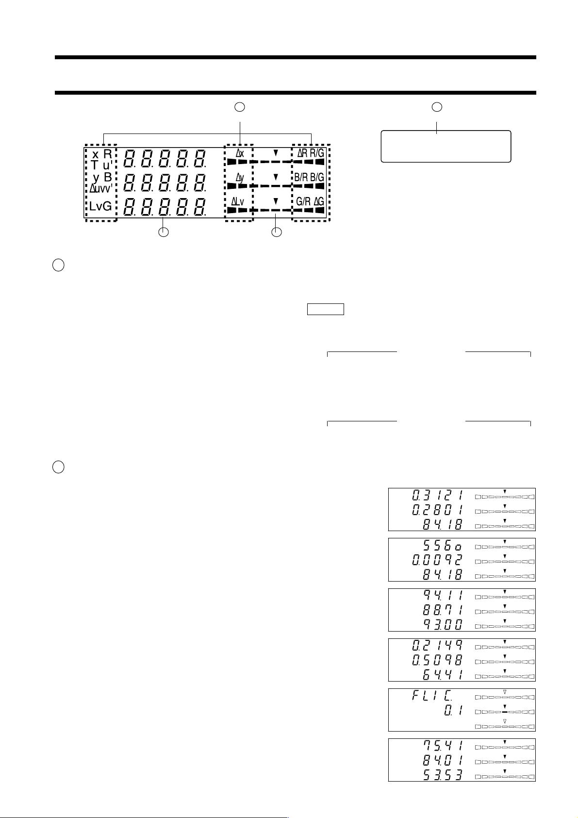
1 Measurement mode ................................. Displays the measurement mode in which the measured values are
displayed.
Measurement mode switches from one to another as shown below
each time the MODE key is pressed. (Page 40)
When LED Universal Measuring ø27 Probe(CA-PU32/35) or LED
Universal Measuring ø10 Probe(CA-PSU32/35) is connected,
Analyzer mode
xyLv→T∆uvLv→RBG (R/G, B/G, ∆G)→RBG (∆R, B/G, G/R)→
u'v'Lv→XYZ →xyLv
When LED Flicker Measuring ø27 Probe(CA-P32/35) or LED Flicker
Measuring ø10 Probe(CA-PS32/35) is connected,
Analyzer mode
xyLv→T∆uvLv→RBG (R/G, B/G, ∆G)→RBG (∆R, B/G, G/R)→
u'v'Lv→Flicker**→XYZ →xyLv
Installation/Connection
2 Digital display section ............................. Displays the measured values.
● When xyLv measurement mode is selected
x, y and Lv are displayed.
● When T∆uvLv measurement mode is selected
T, ∆uv and Lv are displayed.
T (correlated color temperature) is displayed in three significant digits.
● When an analyzer measurement mode is selected
R, B and G are displayed. R-reference and G-reference are available.
(The same contents are displayed in the digital display area, whether
R-reference or G-reference.)
● When u'v'Lv measurement mode is selected
u', v' and Lv are displayed.
● When flicker measurement mode** is selected
Flicker** is displayed. The display range is from 0.0 to 999.9%.
● When XYZ measurement mode is selected
X, Y and Z are displayed. (X, Y and Z from top to bottom)
Lv
∆uv
Lv
Lv
x
y
T
R
B
G
u'
v'
∆x
∆y
∆Lv
∆x
∆y
∆Lv
R/G
B/G
∆G
∆x
∆y
∆Lv
∆x
∆y
∆Lv
1919
Page 22
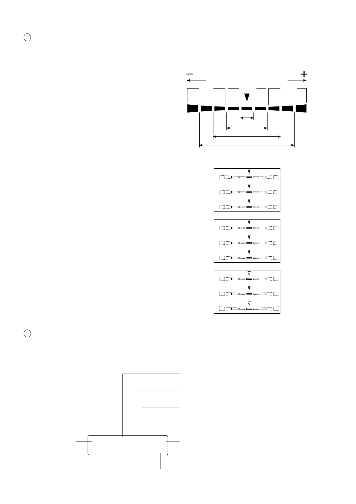
3 Analog display section ............................ Displays the difference (%) between the measured value and the tar-
∆x
∆y
∆Lv
R/G
B/G
∆G
get color or the difference (%) between measured values.
The range for each dot can be set between 0.1 and 99%. (Page 69)
● How to read/when the range is set in “n” %
except flicker mode
For a description of flicker mode refer to page 69.
Red Green Red
The range has been set to 10% prior to factory shipment.
● When xylv, T∆uvLv, u'v'Lv or XYZ measurement
mode is selected
∆x, ∆y and ∆Lv are displayed.
● When an analyzer measurement mode is selected
For G-reference R/G, B/G and ∆G are displayed.
For R-reference ∆R, B/R and G/R are displayed
● When flicker mode* *is selected Flicker is dis-
played.
-
n×8%
or lower
Below ±n%
Below ±n×2%
Below ±n×4%
Below ±n×8%
+n×8% or
higher
4 LCD display section ................................ Displays the memory channel, probe no., ID name, warning and set-
tings.
In case of error, an error message will appear.
(For a description of what to do in case of error, refer to page 103.)
Displays the currently selected SYNC mode. (NTSC,
PAL, EXT, UNIV, INT) (Page 38)
Displays the currently selected measurement speed.
(A.F.S) (Page 36)
Displays the calibration mode for the currently selected memory channel. (d.h.a.m) (Page 57)
Probe no. (Page 43)
Memory channel
(Page 48)
CH00 EXT Ad P1A
[MINOLTA ]
Probe type (A, B, C, D) (Page 43)
ID name display area (Page 67)
20
Page 23

<Out of Measurement Range>
[For xylv, T
● When the measurement range is exceeded Digital display : “– – – – –”
[For T
● T or ∆uv are out of Digital display : “– – – – –”
the display range (T and ∆uv)
∆∆
∆uvLv, u'v'Lv or XYZ,Analyzer Mode]
∆∆
∆∆
∆uvLv Mode]
∆∆
Analog display : Not lit
LCD display : “OVER”
[For Flicker Mode**]
● When the measured value has Digital display : “– – – – –”
exceeded 999.9% Analog display : Not lit
LCD display : “FLICKER ERROR OVER”
● When Lv(luminance) is the following Digital display : “– – – – –”
under 0.1cd/m2 for LED Flicker Measuring ø27 Probe
(CA-P32/35)
under 0.3cd/m2 for LED Flicker Measuring ø10 Probe
(CA-PS32/35)
Analog display : Not lit
LCD display :
FLICKER ERROR UNDER
“
Installation/Connection
”
**Flicker Mode is a function which can be used only when LED Flicker Measuring ø27 Probe(CA-P32/35) or LED Flicker Measuring ø10
Probe(CA-PS32/35) is connected.
21
Page 24

22
Page 25
Installation/Connection
This section explains how to install the instrument, connect
AC power, turn ON ( | )/OFF(●●) the power, and input the ver-
tical synchronizing signal.
About Installation
Provides operating environmental conditions for the instrument and notes
on installation.
About Connection
Explains how to connect measuring probes and connect the power cord.
(It also explains installation method of the optional 4-Probe Expansion Board.)
* Before turning on the power : Refer to pages 85 to 88 if you are going to communicate the instrument with the
PC via RS-232C or USB.
Page 25
Page 26
Installation/Connection
Turning the Power ON ( | )/OFF(●● )
Explains how to turn ON ( | )/OFF(●● ) the power.
Page 29
23
Page 26
SAFETY WARNING
(Failure to adhere to the following points may re-
sult in death or serious injury.)
Do not use the instrument in areas where flam-
mable or combustible gases (gasoline fumes etc.)
are present.
Doing so may result in a fire.
If dust has entered through the vents and collected
inside the instrument, do not use the instrument.
Doing so may result in a fire.
For periodic inspection, contact a Konica Minolta
authorized service facility.
Always use the AC power cord supplied as a stan-
dard accessory with the instrument, and connect
it to an AC outlet (100-240V , 50-60 Hz).
Connecting to a voltage other than that specified
may result in damage to the instrument, fire or
electric shock.
• Do not bend, twist or pull the AC power cord
excessively.
• Do not place heavy items on the AC power cord
or scratch it.
• Do not modify the AC power cord.
Doing so may damage it, resulting in fire or elec-
tric shock.
When disconnecting the AC power cord’s plug, al-
ways hold the plug and pull it to remove it. Never
pull the AC power cord itself as it may be dam-
aged, resulting in fire or electric shock.
Also do not insert or disconnect the AC power cord’s
plug with wet hands. Doing so may cause electric
shock.
If you are not going to use the instrument for a long
time, disconnect the AC power cord from the AC
outlet. Dirt or water may accumulate on the prongs
of the AC power cord’s plug and it may cause a
fire. If there is any dirt or water on the prongs, it
must be removed.
SAFETY PRECAUTIONS
• Do not place the instrument on an unstable or
sloping surface.
• When you carry the product, take care not to let
it drop.
Doing so may result in its dropping or overturn-
ing, causing injury.
(Failure to adhere to the following points
may result in injury or damage to the in-
strument or other property.)
Be sure to connect the AC power cord’s plug to an
AC outlet that has a protective grounding terminal.
Also make sure that peripheral devices (e.g. PC)
are connected to AC outlets that have a protective
grounding terminal. Failure to do so may result in
electric shocks.
2424
Page 27

About Installation
The operating environmental requirements are given in the “Specifications” of this manual. The instrument must
be installed in a place that completely meets these requirements. (Page 110-113)
<Notes on Installation>
● Using the instrument in direct sunshine in midsummer or near a heater will cause a rapid rise in its temperature
resulting in breakdown.
Special care must be taken when handling the instrument in such an environment. In addition, take care not to
allow the vents to become blocked. Do not use the instrument in poorly ventilated areas.
● Do not use the instrument in a place where the temperature changes rapidly, since measured values will be
incorrect.
● The instrument must not be used in areas where there is an excessive amount of dust or where the humidity is
excessively high.
● The instrument must not be used if foreign matter such as water and metal objects enter it, doing so is very
dangerous.
● The AC power cord must not be pulled or bent excessively nor must excessive force be exerted on it. Doing so
may result in wire breakage.
● The AC power cord must not be connected to an AC line on which excessive noise is present.
● If any irregularity or abnormality is found, turn OFF(●●) the power immediately, disconnect the AC power
cord, and refer to “Troubleshooting Guide” on page 107.
Installation/Connection
2525
Page 28
About Connection
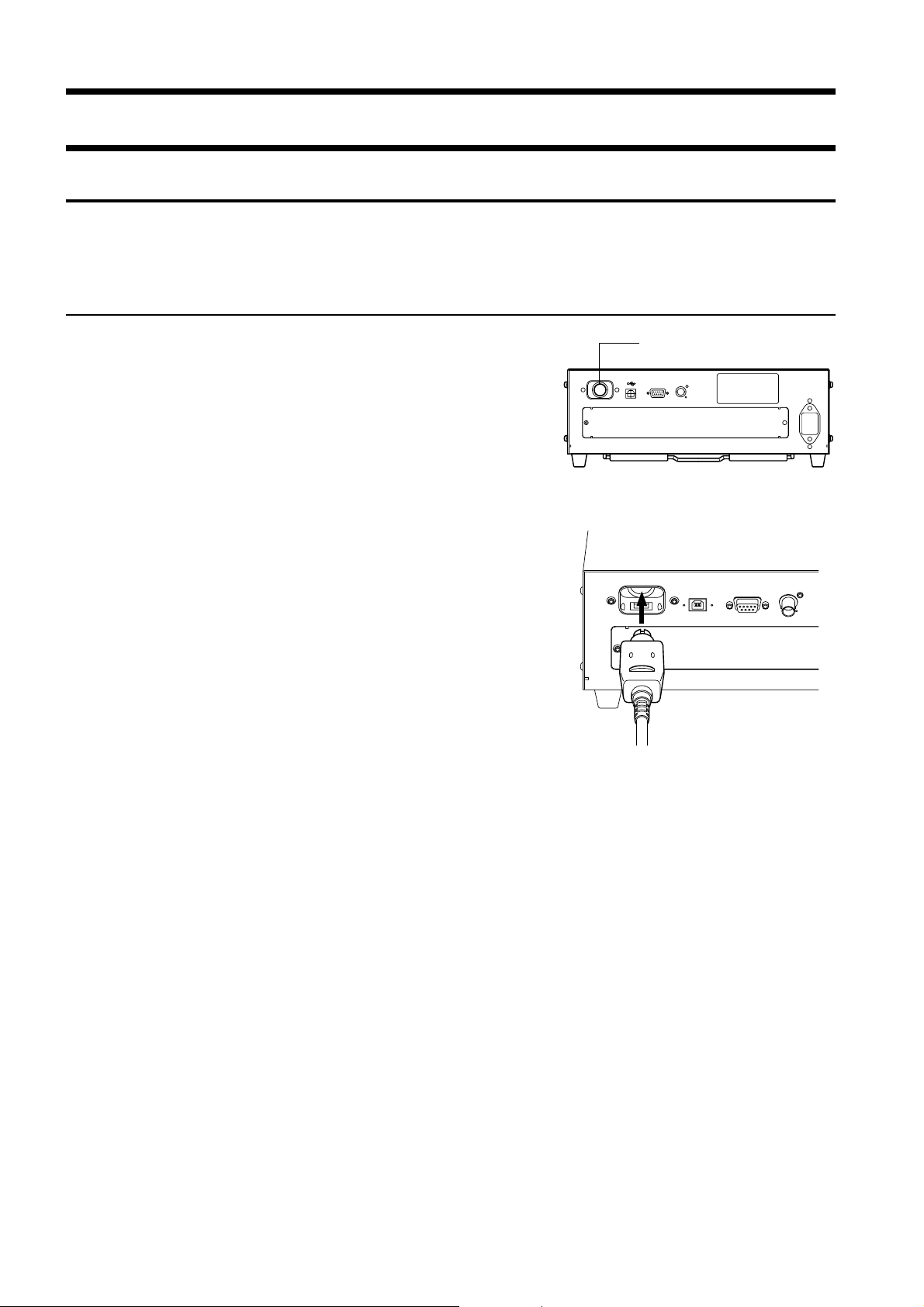
1. Connecting a Measuring Probe
Before setting the POWER switch to ON ( | ), a measuring probe must be connected to the probe connector [P1] on
the instrument.
[Connecting Method]
1. Set the POWER switch to OFF (“O” position).
2. Insert the probe’s plug into the probe connector
[P1], with the probe serial no. facing down.
3. Check that the plug is inserted all the way and
connected firmly
• When disconnecting the measuring probe, set the POWER
switch to OFF(●● ) first, and pull the probe by holding the
plug. Never pull the probe by its cord.
Probe connector [P1]
<Notes when Connecting the Probe>
● Never connect or remove the measuring probe while the POWER
switch is ON ( | ).
● When connecting/disconnecting the measuring probe, always hold
the plug and connect/disconnect it. In addition, do not pull or bend
the cord excessively or exert excessive force on it. Doing so may
result in wire breakage.
● The Measuring Luminance Range will vary according to the type
of Measuring Probe.
● When measurement is implemented, the same Measuring Probe
to be used for the User Calibration is necessary. If measurement
is carried out by connecting the different Measuring Probe, error
message E1 will be displayed.
26
Page 29
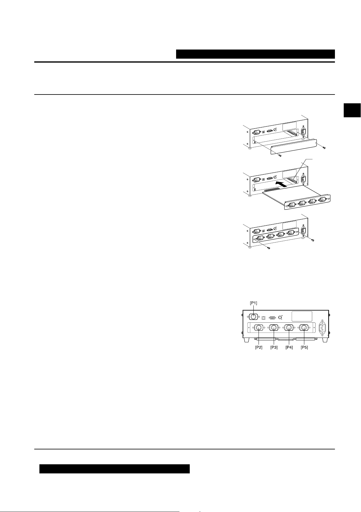
2. Installing the 4-Probe Expansion Board CA-B15
When the optional 4-Probe Expansion Board CA-B15 is used
Installing the optional 4-Probe Expansion Board CA-B15 in the instrument allows simultaneous measurement of
the colors or flicker** at up to 5 points on the display’s surface. Install the expansion board as shown below.
[Installation Method]
1. Remove the cover of the 4-Probe Expansion Board slot.
1 Set the POWER switch on the instrument to OFF(●●).
2 Remove the two screws from the slot cover, and remove the cover.
2. Install the 4-Probe Expansion Board.
1 Place the 4-Probe Expansion Board along the right- and left-
side guides in the slot.
2 Push the board all the way and make sure that the board is con-
nected properly.
3 Secure the board with the two screws that were removed previ-
ously.
• Repeatability of the measurement value becomes worse when
the fixation by the screw is incomplete.
• To remove the board, remove the two screws first, then hold the
grip of the board and pull it out. After the board is removed,
attach the cover to the slot.
Guide
Installation/Connection
<Notes on Installation>
● When installing/removing the 4-Probe Expansion Board, always set the POWER switch to OFF(●● ) and pull
the AC power cord from the AC outlet first.
● Do not touch the connectors (gold plated parts) or ICs on the 4-Probe Expansion Board with your hands. If oil
or similar matter adheres to the connectors, wipe them with a soft, dry cloth.
<Connecting Measuring Probes>
The following 8 types of measuring probes can be connected.
●
LED Universal Measuring ø27 Probe CA-PU32 /CA-PU35
●LED Universal Measuring ø10 Probe CA-PSU32/CA-PSU35
●
LED Flicker Measuring ø27 Probe CA-P32 /CA-P35
●
LED Flicker Measuring ø10 Probe CA-PS32 /CA-PS35
A total of five probes can be connected. When connecting two or more probes, always make sure that one of them
is connected to the probe connector [P1].
Connect necessary number of probes to the probe connectors [P2] to [P5] on the 4-Probe Expansion Board. You do not
have to connect any probes to those connectors ([P2] to [P5]). Probes can be connected to any connectors ([P2] to [P5]).
The Measuring Luminance Range will vary according to the type of Measuring Probe.
6 types of optionally available Measuring Probes can be connected.
As a display model to be measured and the Measuring Luminance Range of Measuring Probe will vary according
to the type, please install one that is fit for your use. Also, different types can be coresident.
● The connecting method for connectors [P2] to [P5] is the same as that for [P1]. (Refer to page 26.)
Notes when connecting probes: Probe connectors on the 4-Probe Expansion Board where no probe is connected must be capped.
**Flicker Mode is a function which can be used only when LED Flicker Measuring ø27 Probe(CA-P32/35) or LED Flicker Measuring ø10
Probe(CA-PS32/35) is connected.
When the optional 4-Probe Expansion Board CA-B15 is used
In Flicker Mode with LED Flicker Measuring ø27 Probe(CA-P32/35) or LED Flicker Measuring ø10 Probe(CA-PS32/35) connected, a
selected probe cannot be changed to LED Universal Measuring ø27 Probe(CA-PU32/35) or LED Universal Measuring ø10 Probe(CA-
PSU32/35).
27
Page 30
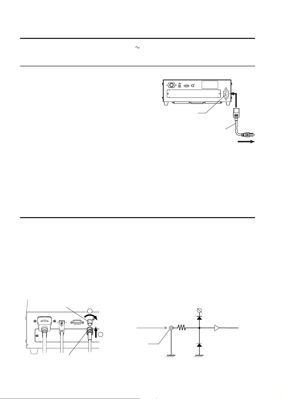
3. Connecting the Power
Power voltage range for the instrument — 100 to 240V
[Connection Method]
1. Set the POWER switch to OFF (“O” posi-
Main body
tion).
2. Connect the AC power cord’s connector to
2
the AC power connector on the instrument.
The AC power cord must be connected as shown in the
figure.
3. Insert the AC power cord’s plug to an AC outlet.
AC power connector
AC power cord
3
To an AC outlet
<Notes on Power Connection>
● Never connect or remove the AC power cord while the POWER switch is ON.
● When connecting/disconnecting the AC power cord, always hold the plug and connect/disconnect it. In addi-
tion, do not pull or bend the cord excessively or exert excessive force on it. Doing so may result in wire
breakage.
● Be sure to connect the AC power cord's plug to an AC outlet that has a protective grounding terminal.
4. Inputting the Vertical Synchronizing Signal
The vertical synchronizing signal from the display can be input to the instrument to allow synchronous measurement (when EXT SYNC mode is selected).
However, if another SYNC mode is selected, it is not necessary to input the vertical synchronizing signal.
Connect the BNC cable of the vertical synchronizing signal (frequency: 40 to 200 Hz) used for the display to the
connector on the rear panel of the instrument as shown below. Before connecting, make sure that the power to both
the instrument and display is turned OFF.
In the case of flicker mode, a vertical synchronizing signal of 40 to 130 Hz must be input.
(Only when LED Flicker Measuring ø27 Probe(CA-P32/35) or LED Flicker Measuring ø10 Probe(CA-PS32/35)
is connected.)
Circuit diagram
Vertical synchronizing
signal input terminal
2
1
(Flicker mode: 40 to 130 Hz)
BNC connector
C-MOS logic level
Input the vertical
synchronizing signal.
(40 to 200 Hz)
74HC14
(operated with 5V)
Connector type: BNC
*To synchronize measurement with the display’s vertical synchronizing signal, EXT must be selected as the
SYNC mode. For details, refer to page 36.
2828
Page 31

Turning the Power ON ( | )/OFF (●●)
1. Turning the Power ON ( |
Before setting the POWER switch to ON ( | ), prepare the following.
)/OFF (●●
)
1. Connect a measuring probe to the probe connector [P1]. (Page 26)
• To synchronize measurement with the ... 1
display’s vertical synchronizing signal (Page 28)
(EXT is selected as the SYNC mode)
• To perform measurement .......................
with two or more measuring probes
• To communicate with the PC .................
via RS-232C
• To communicate with the PC via USB...
Input the vertical synchronizing signal that is used for the display.
1
Install the 4-Probe Expansion Board (option) in the
in
strument. (Page 27)
2 Connect necessary number of probes to the probe connec-
tors [P2] to [P5]. (Pages 26 and 27)
1
Connect the instrument’s RS-232C connector to the PC. (Page 86)
1
Connect the instrument’s USB connector to the PC. (Page 88)
2. Connect the AC power cord to an AC outlet. (Page 28)
[Turning the Power ON ( | )]
Installation/Connection
Set the POWER switch to ON ( | ).
If the instrument is connected to external equipment, set the instrument’s
POWER switch to ON ( | ) first, then
turn ON ( | ) the power to the external
equipment.
PROBE [P1]
NO.XXXXXXXX A
DARKEN PROBE
PUSH 0-CAL KEY
[Turning the Power OFF (●●)]
If the instrument is connected to external equipment, turn OFF (●● ) the power to the external equipment
first, then set the instrument’s POWER switch to OFF (●● ).
<Error Messages in LCD Display Section>
● “SET MAIN PROBE” (After the POWER switch is set to ON ( | ))
• Cause 1 : The measuring probe is not connected to the probe con-
nector [P1] properly.
• Action 1: Set the POWER switch to OFF (●●), then connect the measuring probe to the probe connector
[P1] properly. (Before connecting/disconnecting the measuring probe, make sure that the
POWER switch is set to OFF (●● ).)
● “PROBE ERROR”
• Cause 1 : A measuring probe was connected or disconnected while
the POWER switch was ON ( | ).
• Action 1: Set the POWER switch to OFF (●●) first, connect necessary measuring probes, then set the
POWER switch to ON ( | ). (Before connecting/disconnecting the measuring probe, make sure
that the POWER switch is set to OFF (●● ).)
Probe serial no.
2929
“C ”:
“D ”:
“ A ” :
“ B ” :
…
For other error messages, refer to page 101.
LED Universal Measuring ø27 Probe
(CA-PU32/35)
LED Universal Measuring ø10 Probe
(CA-PSU32/35)
LED Flicker Measuring ø27 Probe
(CA-P32/35)
LED Flicker Measuring ø10 Probe
(CA-PS32/35)
SET MAIN PROBE
PROBE ERROR
Page 32

2. Instrument Status at Power-ON
The instrument has been set prior to factory shipment so that it will be set as follows when the POWER switch is
set to ON.
1 Measurement mode Page 40 xyLv mode
2 Memory channel no. Page 48 CH00
3 Target color Page 63 x = 0.3127 y = 0.3293 Lv = 160.0 (cd/m2)
4 PROBE Page 43 P1
5 SYNC mode Page 36 EXT mode
6 ID name Page 67 Consists of Blank spaces only.
7 Analog display range value Page 69 10% (all ranges)
8 Measurement speed Page 36 AUTO
9 Number of display digits Page 42 4 digits
10
Calibration standard Page 50 6500K Konica Minolta’s standard data
11
RS232C baud rate Page 87 38400bps
12
Calibration data (stored) in CH00 to CH99 Page 51 6500K Konica Minolta’s standard data
13
Luminance unit Page 32 cd/m
<Changing the Instrument Status at Power-ON>
Change necessary parameters and press the key for more than five seconds. A bleep will sound, followed by a
whistling sound when the settings are saved. The instrument will start with the new settings when the power is
turned ON next time. (The selected mode and memory channel etc. will be stored in the instrument’s memory, and
they will remain effective even if the POWER switch is set to OFF.)
2
* For details, refer to the pages given in the above table.
Changing Method for parameters 1 and 2
1 Measurement mode .........Press the MODE key.
2 Memory channel ............. Press the CH
and keys.
Changing Method for parameter 3
3 Target color value ............The current target color will be changed if you
select a mode other than flicker and then enter a
target color, or select user calibration or enter
the RGB emission characteristic for analyzer
mode.
30
Page 33

Changing Method for parameters 4 to
11
For parameters 4 to
11
, switch the LCD display section to the menu selec-
tion screen as explained below.
1.Press the key.
The LCD display section will switch to the menu selection screen.
2. Press the key until the desired screen is displayed.
Each time the key is pressed, the screen will switch in the order
PROBE→SYNC→ID Name input→RANGE→Measurement Speed→
Number of Digits→Calibration Standard data→RS232C Baud
Rate→PROBE.
3. Press the key to select the desired setting, and
press the key to confirm the selection.
For the ID name and range, enter the desired settings using the ten-key,
ALPHA and alphabet keys, then press the
tings.
Changing Method for parameter 12 13
For the setting method, refer to the page given in the above table.
<About the REMOTE Key>
The REMOTE key should not be pressed unless you are going to communicate with the PC via RS-232C or USB.
• Pressing the REMOTE key sets the instrument in remote mode, enabling communica-
tion with the PC via RS-232C or USB.
(The REMOTE LED will light up.) In remote mode, no keys other than the REMOTE
key are effective.
To cancel remote mode, press the REMOTE key again.
key to confirm the set-
Menu selection screen
MENU : SELECT
PUSH SPACE KEY
PROBE selection screen
SELECT : PROBE
P1 35881112 A
SYNC selection screen
SELECT : SYNC.
ID name input screen
CH01 EXT Ad P1
[ ]
RANGE setting screen
RANGE x,y Lv
(%) 10 10
Measurement speed selection screen
SELECT : M-SPD
AUTO
Number of display digits selection screen
SELECT : DISP.
4 FIGURES
RS-232C baud rate selection screen
SELECT : BAUD
38400 BPS
EXT
Installation/Connection
31
Page 34

3. About the change of Luminance Unit
This instrument allows you to switch the unit for the displayed luminance between “cd/m2” or “fL”. The method is
given below.
1. Set the POWER switch to ON while holding down the MODE key.
“ ” will appear.
” will be added one after another as shown.
“
2. Press the
key before a total of sixteen asterisks appear.
Keeping the key held down will display as shown below, switching the luminance unit from one to
another.
Unit before Unit after
fL → cd/m
2
cd/m
→ fL
2
The newly set luminance unit will remain unchanged until it is changed again by the above method, even if
the power is turned OFF.
* At the time of shipment, the luminance unit is set as cd/m
2
.
32
Page 35

Measurement Preparation
The Measurement Preparation section explains preparations
(instrument setting, zero calibration) that are required prior to
measurement.
Zero Calibration
Explains the zero point adjustment method.
(Measurement cannot be performed if zero calibration has not been completed.)
Selecting, Masurement Speed, SYNC Mode, Measurement Mode and the Number of Display Digits
Explains how to select SYNC mode, that selects measurement time according to the display’s
vertical scanning frequency, as well as explaining how to select display mode and the number of
display digits.
Page 34
Page 36
Measurement Preparation
When the optional 4-Probe Expansion Board CA-B15 is used
Selecting probe no.
Explains how to select the measuring probe whose measured value is to be
displayed.
Page 43
To the Setting section
* Go to the Measurement section if you are going to perform measurement using Konica Minolta’s
calibration standard and are not going to use analog display.
33
Page 36

Zero Calibration
DARKEN PROBE
PUSH 0-CAL KEY
ZERO CALIBRATION
CH00 EXT Fd P1A
E1 [
]
Zero calibration performs zero point adjustment while blocking entry of light into the measuring probe’s receptor.
Zero calibration must be performed whenever the POWER switch is set to ON.
1. Performing Zero Calibration
<Notes on Zero Calibration>
● If the luminance of the display to be measured is 1.0 cd/m2 or less (if LED Universal Measuring ø10 Probe(CA-
PSU32/35) or LED Flicker Measuring ø10 Probe(CA-PS32/35), 3.0 cd/m
after elapse of 30 minutes or more after the POWER switch is set to ON.
When measuring such a low-luminance display for a long period of time, perform zero calibration approximately every hour.
● Perform zero calibration if the ambient temperature has changed.
● Zero calibration can be performed anytime even if “PUSH 0-CAL KEY” is not displayed.
● Never direct the measuring probe toward the illuminant with illuminance exceeding the measurement range
during zero calibration.
● Never press any keys during zero calibration. Doing so will cause completion of zero calibration to take more
time.
● When the optional 4-Probe Expansion Board CA-B15 is used
Zero calibration will be performed simultaneously with all the connected measuring probes.
2
or less), perform zero calibration
[Operating Procedure]
Before starting zero calibration, check that a measuring probe is connected to the probe connector [P1] on the
instrument.
3
1
Pinting ring
2
1. Check that the POWER switch is set to ON.
2. Set the pointing ring to the 0-CAL position.
Be careful because zero calibration can't be done properly.
•
Don’t turn the tip of Probe to the high illuminant with illuminance exceeding the measurment range.
When the optional 4-Probe Expansion Board CA-B15 is used
Set the switching ring of every measuring probe to the 0-CAL
position. Zero calibration will not be performed correctly if the
switching ring of any of the measuring probes is not set to the 0CAL position.
Message displayed
when the POWER
switch is set to ON
Press the 0-CAL key.
During zero calibration
3. Press the 0-CAL key.
Measurement will start automatically at the end of zero
calibration.
End of zero calibration
“E1” is always displayed if the instrument is used for
the first time since shipment from the factory.
34
Page 37

<Error Messages in LCD Display Section> … For other error messages, refer to page 103.
OFFSET ERROR
PUSH O-CAL KEY
ZERO CALIBRATION
TOO BRIGHT
DARKEN PROBE
PUSH 0-CAL KEY
● “TOO BRIGHT” (During zero calibration)
• Cause : Light is entering the measuring probe’s receptor.
• Action : Block the light completely, and when “PUSH 0-
CAL KEY” appears press the 0-CAL key again
to start zero calibration.
● “E1” (After completion of zero calibration)
• Cause : “E1” is displayed if the instrument is used for the
first time since shipment from the factory, because
no target color has been set.
• For other cases, refer to page 103.
CH00 EXT Ad P1A
E1 [
The message
switches
automatically.
Approx. 1 second
]
2. Zero Calibration Check Method
If you want to check whether zero calibration has been performed correctly, block entry of light into the measuring
probe’s receptor using a blackout curtain etc.
• If the message shown on the right appears in the LCD
display section, perform zero calibration again.
• Zero calibration has been completed correctly if “000”
blinks for “Lv” in the digital display section. If a value
other than “000” is displayed, perform zero calibration
again.
Measurement Preparation
(Note) Even if “OFFSET ERROR” is displayed, measurement will start if the measuring probe’s receptor is exposed to light.
35
Page 38

Selecting, Measurement Speed, SYNC Mode, Display Mode and the Number of Display Digits
1. Selecting the Measurement Speed
Select the measurement speed according to your application.
If the measurement speed is changed, display frequency of the measurement results will change accordingly.
The measurement results are displayed at the following frequency.
FAST mode
Requires short measurement time, but measurement accuracy is not sufficient in the case of measurement of a lowintensity display.
SLOW mode
Repeats measurement several times and displays the average. This mode is used when you want to perform accurate measurement.
AUTO mode
Switches measurement speed to FAST or SLOW automatically according to the luminance of the display measures.
Normally, this measurement speed is recommended.
The measurement speed switches from FAST to SLOW or vice versa at the following luminance .
(LED Universal Measuring ø27 Probe) FAST → SLOW :When Lv drops below 4.0cd/m
(CA-PU32/35) SLOW → FAST :When Lv exceeds 6.0cd/m
(LED Universal Measuring ø10 Probe) FAST → SLOW :When Lv drops below 12.0cd/m
(CA-PSU32/35) SLOW → FAST : When Lv exceeds 18.0cd/m
(LED Flicker Measuring ø27 Probe) FAST → SLOW : When Lv drops below 2.0cd/m
(CA-P32/35) SLOW → FAST : When Lv exceeds 3.0cd/m
(LED Flicker Measuring ø10 Probe) FAST → SLOW : When Lv drops below 6.0cd/m
(CA-PS32/35) SLOW → FAST : When Lv exceeds 9.0cd/m
2
.
2
.
2
.
2
.
2
.
2
.
2
.
2
.
(In the case of Flicker Mode**, the measurement speed is always FAST mode.)
When the optional 4-Probe Expansion Board CA-B15 is used
(LED Universal Measuring ø27 Probe) FAST → SLOW : When Lv for any of probes drops below 4.0 cd/m2.
(CA-PU32/35) SLOW → FAST : When Lv for all the probes exceed 6.0 cd/m
2
.
(LED Universal Measuring ø10 Probe) FAST → SLOW : When Lv for any of probes drops below 12.0 cd/m
(CA-PSU32/35) SLOW → FAST : When Lv for all the probes exceed 18.0 cd/m
2
.
(LED Flicker Measuring ø27 Probe) FAST → SLOW : When Lv for any of probes drops below 2.0 cd/m
(CA-P32/35) SLOW → FAST : When Lv for all the probes exceed 3.0 cd/m
2
.
2
.
2
.
(LED Flicker Measuring ø10 Probe) FAST → SLOW : When Lv for any of probes drops below 6.0 cd/m
(CA-PS32/35) SLOW → FAST : When Lv for all the probes drops exceed 9.0 cd/m
Currentlys elected measurement speed
CH00 EXT Ad P1A
[ ]
F: FAST mode
S: SLOW mode
A: AUTO mode
36
2
.
2
.
Page 39

MENU : SELECT
PUSH SPACE KEY
SELECT : M-SPD
AUTO
SELECT : M-SPD
SLOW
SELECT : M-SPD
FAST
CH00 EXT Fd P1A
[ ]
[Operating Procedure]
PQRS7TUV8WXYZ
GHI4JKL5MNO LOCK
White1ABC2DEF- SPACE
Red0Green.Blue
MENU
9
ALPHA
6
CAL
3
1
2
3
ENTER
4
1. Press the key.
The LCD display section will switch to the menu selection
screen.
2. Press the key to open the measurement speed
selection screen.
Each time the key is pressed, the screen will switch in
the order PROBE → SYNC → ID Name input → RANGE
→ Measurement Speed → Number of Digits → Calibration standard→ RS232C Baud Rate → PROBE.
3. Press the key to display the desired measure-
ment speed.
Each time the key is pressed, the measurement speed
switches in the order [AUTO] → [SLOW] → [FAST] →
[AUTO].
Menu selection screen
Measurement speed selection screen
Press the key
until the desired
measurement
speed appears.
Measurement Preparation
“F” is displayed when the [FAST] was selected.
4. Press the key to confirm the selection.
* By default (factory setting), the instrument is set so that [AUTO] will be selected automatically when the POWER switch is set to
ON( | ).
* To cancel selection of measurement speed, press the
<Notes when Selecting the Measurement Speed>
● The selected measurement speed data will be kept even if the POWER switch is set to OFF (●● ).
The selected measurement speed will be effective when the POWER switch is set to ON( | ).
key.
**Flicker Mode is a function which can be used only when LED Flicker Measuring ø27 Probe(CA-P32/35) or LED Flicker Measuring ø10
Probe(CA-PS32/35) is connected.
37
Page 40

2. Selecting SYNC Mode
MENU : SELECT
PUSH SPACE KEY
SELECT : SYNC.
EXT
SELECT : SYNC.
UNIV
CH00 EXT Ad P1A
[ ]
In SYNC mode, measurement time (sampling time) is selected according to the display’s vertical scanning frequency.
The following five SYNC modes are available. Select the SYNC mode suitable for the display to be measured.
SYNC Mode
NTSC
PA L
EXT
UNIV.
INT
Used for measurement of NTSC monitors
Used for measurement of PAL and SECAM
monitors
Used to synchronize measurement with the
monitor’s vertical synchronizing signal (frequency: 40 to 200 Hz) that is input to the
instrument. (For how to input the vertical synchronizing signal, refer to page 28.)
Used for measurement of any monitors, for
instance, when the frequency of monitor’s vertical synchronizing signal is unknown or when
the vertical synchronizing signal cannot be input into the instrument for some reason.
If the frequency of the monitor’s vertical synchronizing signal is known, set it to be used
for measurement.
[Selecting Method]
Description
Measurement time
(Sampling time)
33.3 ms
40.0 ms
(1 vertical scan
cycle) × 2
100 ms
(1 vertical scan
cycle) × 2
Ve rtical scanning
frequency
60 Hz
50 Hz
40 to 200 Hz
(Flicker
40 to 130 Hz)
—
40 to 200 Hz
(Flicker
40 to 130 Hz)
Display’s vertical
synchronizing
signal
Not required
Not required
Required
Not required
Not required
1. Press the key.
The LCD display section will switch to the menu selection
screen.
2. Press the key to open the SYNC selection
screen.
Each time the key is pressed, the screen will switch in the
order PROBE → SYNC → ID Name input → RANGE →
Measurement Speed → Number of Digits → Calibration
standard→ RS232C baud rate → PROBE.
3. Press the key to display the SYNC mode you
want to select.
Each time the key is pressed, SYNC mode switches in
the order EXT→UNIV→INT→NTSC→PA L→EXT.
“INT” allows you to change the synchronizing frequency.
PQRS7TUV8WXYZ
GHI4JKL5MNO LOCK
White1ABC2DEF- SPACE
Red0Green.Blue
Menu selection screen
SYNC selection screen
SYNC Mode
MENU
9
ALPHA
6
CAL
3
ENTER
1
2
3
4
SYNC selection screen
Press the key
until the desired
SYNC mode is
displayed.
38
Page 41

4. Press the key to confirm the selection.
*To use EXT mode, the vertical synchronizing signal used for the display must be input to the instrument. (Page 28)
* By default (factory setting), the instrument is set so that EXT mode will be selected automatically when the POWER switch is set to ON.
If you want to change this setting, refer to page 29.
<Changing the Synchronizing Frequency for INT>
Select INT as explained above, and enter the desired frequency using the number-key.
SELECT : SYNC.
INT 60.0Hz
<Relationship between Measurement Speed and SYNC Mode>
The measurement time (sampling time) is determined by the selected SYNC mode.
The measurement speed (the number of measurements and outputs per second) is determined by the SYNC mode
and the following conditions.
• Luminance of the display to be measured
• Measurement mode
• Data output (RS-232C or USB)
• In cace RS-232C, Baud rate
• Number of measuring probes to be used (when the optional 4-Probe Expansion Board is used)
The table below shows the measurement speed for each SYNC mode when measurement is performed under the
following conditions.
RS232C
• Luminance of the display to be measured .... No errors and warnings, and the luminance is stable.
• Display mode ................................................ xyLv or Flicker**
• Baud rate....................................................... 38,400 bps
• Number of connected measuring probes ......... 1
xyLv Flicker
FAST SLOW —
NTSC 17 measurements/sec. 4.5 measurements/sec.*
PA L 15 measurements/sec. 4 measurements/sec. 14 measurements/sec.
2
EXT*
UNIV. 7 measurements/sec. 1.5 measurements/sec. —
2
INT*
*1 Applies when luminance Lv is 0.1 cd/m2 or higher for Measuring ø27 probe (CA-PU32/35, CA-P32/35), or 0.3 cd/m2 or higher
for Measuring ø10 probe (CA-PSU32/35, CA-PS32/35).
If Lv is lower than mentioned above, 3.5 measurements/sec. spplies.
*2 The measurement speed for EXT and INT when the vertical scanning frequency is 60 Hz is given.
17 measurements/sec. 4.5 measurements/sec. 16 measurements/sec.
17 measurements/sec. 4.5 measurements/sec. 16 measurements/sec.
1
16 measurements/sec.
Measurement Preparation
USB
• Luminance of the display to be measured .... No errors and warnings, and the luminance is stable.
• Display mode ................................................ xyLv or Flicker**
• Number of connected measuring probes ......... 1
xyLv Flicker
FAST SLOW —
NTSC 20 measurements/sec. 5 measurements/sec.*
PA L 17 measurements/sec. 4 measurements/sec. 14 measurements/sec.
2
EXT*
UNIV. 8 measurements/sec. 1.5 measurements/sec. —
2
INT*
*1 Applies when luminance Lv is 0.1 cd/m2 or higher for Measuring ø27 probe (CA-PU32/35, CA-P32/35), or 0.3 cd/m2 or higher
for Measuring ø10 probe (CA-PSU32/35, CA-PS32/35).
If Lv is lower than mentioned above, 4 measurements/sec. spplies.
*2 The measurement speed for EXT and INT when the vertical scanning frequency is 60 Hz is given.
**Flicker Mode is a function which can be used only when LED Flicker Measuring ø27 Probe(CA-P32/35) or LED Flicker Measuring ø10
Probe(CA-PS32/35) is connected.
20 measurements/sec. 5 measurements/sec. 16 measurements/sec.
20 measurements/sec. 5 measurements/sec. 16 measurements/sec.
39
1
16 measurements/sec.
Page 42

<Error Messages in LCD Display Section>
● “NO SYNC. SIGNAL” (when EXT mode is selected)
•
Cause 1 : The vertical synchronizing signal used for the display is not connected to the terminal on the
instrument.
Action : If EXT mode is selected, input the vertical synchronizing signal to the terminal on the instru-
ment properly.
•
Cause 2 : The frequency of the vertical synchronizing signal used for the display is below 40 Hz or beyond
200 Hz.
Action : Change SYNC mode to UNIV. mode and start measurement.
3. Selecting the Measurement Mode
The following measurement modes are available.
Measurement Mode Description
…
For other error messages, refer to page 101.
xyLv mode
T∆uvLv mode
Analyzer mode
u'v'Lv mode
Flicker mode
G-reference
G Standard
R Standard
R-reference
Used to display/output chromaticity coordinates xy and luminance Lv.
(The analog display section shows ∆x, ∆y and ∆Lv.)
Used to display/output T (correlated color temperature), ∆uv (color difference from
blackbody locus) and luminance Lv.
(The analog display section shows ∆x, ∆y and ∆Lv.)
Used to display meeasurement RBG emission intensities as a percentage of the RGB
emission intensities target color(W). Analog display shows measured ratios R/G and
B/G, and ∆G
Used to display meeasurement RBG emission intensities as a percentage of the RGB
emission intensities target color(W). Analog display shows measured ratios G/R and
B/R, and ∆R
Used to display/output u'v' chromaticity coordinates (CIE 1976 UCS chromaticity
diagram) and luminance Lv.
(The analog display section shows ∆x, ∆y and ∆Lv.)
Used to display flicker amount abtained form contrast format (AC/DC). The unit is %.
Can be selected only when LED Flicker Measuring ø27 Probe(CA-P32/35) or LED
Flicker Measuring ø10 Probe(CA-PS32/35) is connected.
When the optional 4-Probe Expansion Board CA-B15 is used
Can be selected only when LED Flicker Measuring ø27 Probe(CA-P32/35) or LED
Flicker Measuring ø10 Probe(CA-PS32/35) is selected.
XYZ mode
Used to display/output tristimulus values X, Y and Z.
(The analog display section shows ∆x, ∆y and ∆Lv.)
40
Page 43

[Selecting Method]
Press the MODE key to display the measurement mode you want to select.
Measurment
MODE key
Each time the MODE key is pressed, measurement mode will switch as shown below.
xyLv mode
x
y
Lv
∆x
∆y
∆Lv
T∆uvLv mode
∆x
∆y
∆Lv
∆uv
Lv
T
Analyzer mode (G Standard)
R
B
G
R/G
B/G
∆G
Analyzer mode (R Standard)
R
B
G
∆R
B/R
G/R
u'v'Lv mode
u'
v'
Lv
∆x
∆y
∆Lv
When LED Universal Measuring ø27 Probe(CA-PU32/35) is
or LED Universal Measuring
ø10 Probe(CA-PSU32/35) connected,
XYZ mode
∆x
∆y
∆Lv
Flicker mode
Measurement Preparation
When LED Flicker Measuring ø27 Probe(CAP32/35) or LED Flicker Measuring ø10
Probe(CA-PS32/35) is connected,
* By default (factory setting), the instrument is set so that xyLv mode will be selected automatically when the POWER switch is set to ON ( | ).
41
Page 44

4. Selecting the Number of Display Digits
MENU : SELECT
PUSH SPACE KEY
SELECT : DISP.
4 FIGURES
SELECT : DISP.
3 FIGURES
The number of display digits can be selected from 4 or 3.
However, T(correlated color temperature) is always displayed in three digits, and flicker is always displayed up to
the first decimal place.
[Selecting Method]
1.Press the key.
The LCD display will switch to the menu selection
screen.
2. Press the key to open the number of
display digits selection screen.
Each time the key is pressed, the screen will switch
in the order PROBE → SYNC → ID Name input →
RANGE → Measurement Speed → Number of Digits
→ Calibration standard→ RS232C Baud Rate →
PROBE.
3. Press the key until the desired number
of display digits appears.
Each time the key is pressed, the number of display digits switches alternately between “4 FIGURES”
and “3 FIGURES”.
4. Press the key to confirm the selection.
* By default (factory setting), the instrument is set so that “4 FIGURES”
will be selected automatically when the POWER switch is set to ON( | ).
* To cancel selection of the number of display digits, press
key.
PQRS7TUV8WXYZ
GHI4JKL5MNO LOCK
White1ABC2DEF- SPACE
Red0Green.Blue
Menu selection screen
Number of display digits
selection screen
MENU
9
ALPHA
6
CAL
3
ENTER
1
2
3
4
Press the key until
the desired number of
display digits appears.
<Notes on Number of Display Digits Setting>
● The selected number of display digits will be kept even if the POWER switch is set to OFF(●● ).
The selected number of display digits will be effective when the POWER switch is set to ON( | ).
4242
Page 45

CH00 EXT Ad P1A
[ ]
When the optional 4-Probe Expansion Board CA-B04 is used
MENU : SELECT
PUSH SPACE KEY
SELECT : PROBE
P1 35881112 A
SELECT : PROBE
P3 35881113
SELECT : PROBE
P5 35881114
Selecting Probe No.
Measurement will be performed simultaneously with all the connected measuring probes. However, the digital and
analog display sections show only the measurement results taken by the one selected probe.
Follow the procedure given below to select the probe connector No. (P1 to P5) to which the desired measuring
probe is connected.
In this example, a measuring probe is connected to the probe connectors [P1], [P3] and [P5].
[P1]
[P3] [P5]
[Selecting Method]
1. Press the key.
The LCD display section will switch to the menu selection screen.
2. Press the key to open the PROBE selection screen.
Each time the key is pressed, the screen will switch
in the order PROBE → SYNC → ID Name input →
RANGE → Measurement Speed → Number of Digits
→ Calibration standard→ RS232C Baud Rate →
PROBE.
3. Press the key to display the probe no.
you want to select.
Each time the key is pressed, the probe no. switches
in the order [P1]→[P3]→[P5]→[P1].
The probe type is displayed on the right of the probe
serial number by the connected probe.
"C" : LED Universal Measuring ø27 Probe(CA-PU32/35)
"D" : LED Universal Measuring ø10 Probe(CA-PSU32/35)
"A" : LED Flicker Measuring ø27 Probe(CA-P32/35)
"B" : LED Flicker Measuring ø10 Probe(CA-PS32/35)
* When the measurement mode is Flicker Mode, LED Universal Measuring ø27 Probe(CA-PU32/35) or LED Universal Measuring
PQRS7TUV8WXYZ
GHI4JKL5MNO LOCK
White1ABC2DEF- SPACE
Red0Green.Blue
Menu selection screen
PROBE selection screen
ø10 Probe(CA-PSU32/35) is not displayed.
Select the measurement mode other than Flicker Mode, if you want to select LED Universal Measuring ø27 Probe(CA-PU32/35)
or LED Universal Measuring ø10 Probe(CA-PSU32/35).
MENU
9
ALPHA
6
CAL
3
1
2
3
ENTER
4
Press the key until
the desired probe no.
appears.
Measurement Preparation
4. Press the key to confirm the selection.
* By default (factory setting), the instrument is set so that [P1] will be
selected automatically when the POWER switch is set to ON( | ).
4343
Page 46

44
Page 47

Settings Section
This section explains settings that must be made according to
measurement mode.
The setting method varies with measurement mode.
From the Measurement Preparation Section
Outline of the Settings Section
Explains measurement method types and settings that must be made.
(Find out what settings you have to make.)
Page 46
Before Making Each Setting
Gives detailed explanations on memory channels common to each setting and target colors.
When performing measurement
using Konica Minolta’s calibration
standard
Selecting the Calibration Standard
Select 6500K or 9300K.
Page 50
Setting/Changing the Target
Color *1
Explains how to set/change the
target color.
1. Setting/Changing the Target
Color by Measurement
2. Setting/Changing the Target
Color by Entering Values
Page 62
User Calibration
Gives detailed explanation of user
calibration and explains its execu-
tion method.
(Target color is also set at this
time.)
When performing measurement
using user calibration
Page 51
•
To change the target color after user calibration
“Setting/Changing the Target Color”
(Page 60) *1
When performing measurement in
analyzer mode
Analyzer Mode
Gives detailed explanation of ana-
lyzer mode and explains how to
input the RGB emission characteristic for the display’s analyzer
mode.
(Target color is also set at this
time.)
:
•To change the target color after the analyzer
mode RGB emission characteristic is input:
“Setting/Changing the Target Color” (Page
60) *1
Page 58
Page 48
Settings Section
•To set an ID name:
“Setting an ID Name” (Page 67) *2
•To use the analog display function:
“Setting an Analog Display Range”
(Page 69) *3
To the Measurement section
Other Settings
Explains how to set an ID name
and analog display range.
Page 67
45
Settings Checking Method
Explains how to check the set val-
ues and check the probe serial no.
used when the values are set.
Page 73
Page 48

Outline of the Settings Section+
This section explains settings that must be made according to measurement method.
Available measurement methods and the settings that must be made are explained below.
<Measurement by Konica Minolta’s Calibration Standard>
With this method, measurement is performed using Konica Minolta’s calibration standard without calibration.
Even if you are setting the target color to the memory channel CH00, measurement must be performed as explained below.
It is not necessary to set/change the target color if you are not going to use the analog display function.
[Operating Procedure]
<Measurement
Preparation section>
Page 33
When using only the digital
display function
When also using the analog
display function
<Settings section>
Setting/Changing
the Target Color *1
Page 62
Selecting the Calibration Standard
Page 50
<Measurement section>
Measurement
Page 76
• To set an ID name : “Setting an ID Name” (Page 67) *2
• To use the analog display function : “Setting an Analog Display Range” (Page 69) *3
<Measurement by User Calibration>
With this method, user calibration is performed and the obtained correction factor is used for measurement.
Since the target color is also set, the analog display section can show the deviation of the measured values from the
target color. User calibration must be performed in the following cases. (However, it is not possible to perform user
calibration using the memory channel CH00.)
• To correct variation of readings that occur due to the deviation of spectral sensitivity from the CIE 1931 color-
matching function
• To correct difference of readings between instruments when two or more instruments are used
• Correction of difference of readings between measuring probes when two or more probes are used
[Operating Procedure]
<Measurement
Preparation section>
Page 33
• Details of user calibration : “About User Calibration” (Page 51)
• To change the target color after user calibration: “Setting/Changing the Target Color” (Page 62) *1
• To set an ID name : “Setting an ID Name” (Page 67) *2
• To use the analog display function : “Setting an Analog Display Range” (Page 69) *3
<Settings section>
User Calibration
• White calibration
• Matrix calibration
Page 51
<Measurement section>
Measurement
Page 76
46
Page 49

<Measurement by Analyzer Mode>
With this method, the measured colors are expressed in emission intensity of each R, B and G monochromatic light
based on the display’s analyzer mode RGB emission characteristic (which is input to the instrument’s memory
channel) and the target color (W).
Since the target color is also set, the analog display section can show the deviation of the measured values from the
target color. If this method is used when adjusting display’s white balance, the adjustment can be performed more
easily than xyLv mode.
[Operating Procedure]
<Measurement
Preparation section>
Page 33
Inputting RGB emission Characteristic for Display’s Analyzer Mode
<Settings section>
Page 59
<Measurement section>
• Measurement
• Adjusting the White Balance
Page 76
• Details of analyzer mode : “About Analyzer Mode” (Page 58)
• To change the target color after the analyzer
mode RGB emission characteristic is input : “Setting/Changing the Target Color” (Page 62) *1
• To set an ID name : “Setting an ID Name” (Page 67) *2
• To use the analog display function : “Setting an Analog Display Range” (Page 69) *3
*1 About “Setting/Changing the Target Color”
There are the following two methods for setting/changing the target color.
1 Setting/changing the target ...................... The display’s measured values are set as the target color.
color by measurement This method can be used for any memory channels.
2 Setting/changing the target color ............. Set the desired values (x, y, Lv) by entering them directly using the
by entering values instrument’s number-key. This method can be used for memory chan-
nel CH00 only.
Settings Section
*2 About “Setting an ID Name”
An ID name is a name that can be assigned to each memory channel by entering it directly using keys.
This function is useful when you want to specify that user calibration and target color have been set for what type
of display with what colors.
*3 About “Setting an Analog Display Range”
Adjustment is performed by setting the analog display range for each dot.
*To check the specified target color, calibration data for user calibration and probe serial no. used when these settings are made, refer to
“Settings Checking Method” on page 73.
47
Page 50

Before Making Each Setting
1. About Memory Channels
This instrument has a total of 100 channels (CH00 to CH99).
The following items can be set for each of these channels.
1 Correction factor for user calibration ...........................
Memory channel
CH00 EXT Ad P1A
[MINOLTA ]
Probe no.
Probe type
.................................... (For details, refer to page 51.)
2 RGB emission characteristic for analyzer mode .............
ID name
.................................... (For details, refer to page 59.)
3 Target color .................... (For details, refer to page 49.)
4 ID name .......................... (For details, refer to page 67.)
CH00 is provided for calibration that uses Konica Minolta’s calibration standard.
For this channel, only the target color, RGB emission characteristic
MEMORY CH
and keys
for display’s analyzer mode and ID name can be set.
The desired memory channel can be selected by switching from one to another by pressing the MEMORY CH
and keys.
It is also possible to assign an ID name to each memory channel by entering it directly using keys. The ID name is
displayed together with the memory channel no. in the LCD display section.
● If the RGB emission characteristic for analyzer mode is input using a memory channel that has been matrix-
calibrated, the correction factor for matrix calibration will be deleted. (If xylv, T∆uvLv, u'v'Lv or XYZ measurement mode is selected, the Konica Minolta’s calibration standard will be used for measurement.)
● In the case of the same memory channels and probes, the RGB emission characteristic for analyzer mode is
stored in their common memory irrespective of measurement mode. Therefore, when matrix calibration is
performed, the RGB emission characteristic for analyzer mode is also input at the same time.
User Calibration How the memory is used in the case of analyzer mode
Calibration values xyLv for W Calibration values xyLv for R Calibration values xyLv for G Calibration values xyLv for B
Measured value for W Measured value for R Measured value for G Measured value for B
Used for white calibration Used for analyzer mode RGB emission characteristic
Used for matrix calibration
When the optional 4-Probe Expansion Board CA-B15 is used
<Relationship between Memory Channels and Probes>
If the 4-Probe Expansion Board is installed, each probe ([P1] to [P5]) has a total of 100 channels (CH00 to CH99).
The correction factor for user calibration (1), RGB emission characteristic for analyzer mode (2) and target color (3) can
be set for each probe. However, ID name (4) is common to all the probes of the same memory channels.
For instance, if the ID name “CRT-001” is assigned to CH01 when the measured values for probe [P1] are displayed,
“CRT-001” will be displayed for CH01 of all the probes [P1] to [P5].
Probe no. [P1] [P2] [P3] [P4] [P5]
Usable memory channels CH00 to 99 CH00 to 99 CH00 to 99 CH00 to 99 CH00 to 99
ID name (page 65) CH00 to 99 (Common to all probes)
48
Page 51

2. About the Target Color
The target color is the reference used to measure how much the measured values are deviated from a certain color.
The target color can be set for each probe of each memory channel.
The target color is set when the following is performed.
1 User calibration (page 51) ......................... Performing user calibration sets the calibration values as the target
color.
2 Setting/changing the target color ............... Set or change the target color in the following cases.
(page 62) • When you want to set the target color for memory channel CH00
• When you want to set a color that differs from the color used for user
calibration as the target color to a user-calibrated memory channel
• When you want to perform measurement using Konica Minolta’s
calibration standard without user calibration and want to use the
analog display function
3 Inputting the RGB emission .................... When you select analyzer measurement mode and input the RGB
characteristic for analyzer mode emission characteristic for analyzer mode, also set the target color
(page 59) (W).
● Since when calibration factor is input for user calibration/analyzer mode the target color is also set at the same
time, the previously set target color will be deleted.
● To change the currently set target color, change it as explained in “Setting/Changing the Target Color” (page
62). Even if the target color is changed, the currently set correction factor for user calibration and the RGB
emission characteristic for display’s analyzer mode will remain unchanged.
Settings Section
In the case of the same memory channels, the target color is stored in their common memory irrespective of
measurement mode.
As a result, the target color set last will be stored irrespective of how it was set.
In one memory channel and one probe, a correction factor of User Calibration is common to xyLv mode, T∆uvLv
mode, u'v'Lv mode and XYZ mode.
Target color is common to all measuring modes.
49
Page 52

3. Selecting the Calibration Standard (data)
This section explains how to select the instrument’s calibration standard (6500K, 9300K). Selecting the instrument’s
calibration standard will set the calibration standard for CH00 as well as for all the memory channels which have
not been user-calibrated.
[Selecting Method]
1. Press the key.
The LCD display section will switch to the
menu selection screen.
2. Press the key to open the
calibration standard selection screen.
Each time the key is pressed, the screen
will switch in the order PROBE → SYNC
→ ID Name input → RANGE → Measure-
ment Speed → Number of Digits → Cali-
bration Standard → RS232C Baud Rate → PROBE.
PQRS7TUV8WXYZ
GHI4JKL5MNO LOCK
White1ABC2DEF- SPACE
Red0Green.Blue
Menu selection screen
MENU : SELECT
PUSH SPACE KEY
SYNC selection screen
SELECT : STD-DT
6500K
SELECT : STD-DT
9300K
MENU
9
ALPHA
6
CAL
3
ENTER
1
2
3
4
The currently selected calibration
standard will be displayed.
Press the key until the desired
calibration standard appears.
3 . Press the key to display the calibration standard you want to select.
Each time the key is pressed, the calibration standard switches alternately between “6500K” and “9300K”.
4. Press the key to confirm the selection.
The selected calibration standard will be set for CH00 as well as for all the memory channels that have not
been user-calibrated.
* By default (factory setting), the instrument is set so that 6500K mode will be selected automatically when the POWER switch is set to
ON( | ).
*To cancel calibration standard setting, press the
<Notes on Calibration Standard Setting>
● The specified calibration target values will be kept even if the POWER switch is set to OFF (●●). The selected
calibration standard will be set for CH00 as well as for all the non-user-calibrated memory channels when the
POWER switch is set to ON( | ).
key.
5050
Page 53

User Calibration
1. About User Calibration
● User calibration is provided to set the user’s own correction factor to the instrument’s memory channels by
measuring the color of a display and setting the calibration values (x, y, Lv) to the instrument.
Once this factor is set, the values corrected by this factor will be displayed and output each time measurement
is taken.
● This instrument allows two kinds of user calibration; white calibration and matrix calibration.
By default (factory setting), matrix calibration is selected.
● User calibration can be performed for each memory channel. (Except for CH00)
● When the optional 4-Probe Expansion Board CA-B15 is used
User calibration is performed independently for probe ([P1] to [P5]) for each memory channel. (Except for
CH00)
● When this instrument is used for the first time since shipment from the factory, measurement will be performed
based on the calibration carried out by the Konica Minolta’s calibration standard. This applies to all the memory
channels. Once user calibration is performed, the following correction will be made when measurement is
performed using the obtained correction factor.
1 Correction of variation of readings that occur due to the deviation of spectral sensitivity from the CIE 1931
color-matching function
2 Correction of difference of readings between instruments when two or more instruments are used
3 When the optional 4-Probe Expansion Board CA-B15 is used
Correction of difference of readings between measuring probes when two or more probes are used
Settings Section
● At the same time as user calibration is performed for a memory channel, the obtained color will be set as the
target color to that memory channel. The target color is the color used as the reference when displaying how
much the measured values are deviated from a certain color. (Page 49)
● When User Calibration is implemented, the same Measuring Probe to be used for the measurement is necessary.
If measurement is carried out by connecting the different Measuring Probe, error message E1 will be displayed.
In this case, it is necessary to replace it with the Measuring Probe that received User Calibration or you have to
execute User Calibration once again using the Measuring Probe to be used for the measurement.
<When Two or More Instruments are Used>
When two or more instruments are used or when the optional 4-Probe Expansion Board CA-B15 is used to perform
measurement with two or more measuring probes, the difference between readings can be corrected if user calibration is performed as explained below.
When the values of the color to be used as the target are known:
The color set to the reference display is displayed and user calibration is performed for all the bodies (or measuring
probes).
When the values of the color to be used as the target are unknown:
1 Select one master body (or select one master probe).
2 Select “xyLv” measurement mode (page 40), and place the master body’s measuring probe (or the master
probe) against the display on which the target color is displayed.
3
While the probe is placed against the display, press the HOLD key.
4 By using the display on which the target color is displayed and the values displayed at step 3, perform user
calibration for the other bodies (or measuring probes).
5151
Page 54

2. Performing White Calibration
MENU : SELECT
PUSH SPACE KEY
SELECT : PROBE
P1 35881112 A
SELECT : PROBE
P3 35881113
● User calibration cannot be performed with the memory channel CH00.
(CH00 memory channel is provided for measurement that uses the Konica Minolta’s calibration standard.)
● White calibration must be performed for each display type (model).
Characters of displays vary with the display type (model). Because of this, measured values differ even if the
same color is measured. Thus, a different memory channel must be used for each display type (model) to
perform white calibration.
● If white calibration is performed with a memory channel to which the target color has already been set, that
target color will be deleted.
● If white calibration is performed with a memory channel which has already been matrix-calibrated, the correc-
tion factor of the previous matrix calibration will be deleted and the correction factor obtained from the white
calibration will be set.
[Operating Procedure]
5
8,9
3
1 4,10 6,72
When the optional 4-Probe Expansion Board CA-B15 is used
Select the probe no. to be white-calibrated. White calibration can be performed independently for each probe
connector ([P1] to [P5]) for each memory channel.
1 Press the key.
Menu selection screen
The LCD display section will switch to the menu selection screen.
2 Press the key to open the PROBE selec-
PROBE selection screen
tion screen.
Each time the key is pressed, the screen will switch in
the order PROBE → SYNC → ID Name input → RANGE
→ Measurement Speed → Number of Digits → Calibration Standard → RS232C Baud Rate → PROBE.
3 Press the key to display the probe no. you
Press the
until the desired
probe no. appears.
Probe no.
key
want to select.
Each time the key is pressed, the probe no. switches in the order [P1] ….
4 Press the key to confirm the selection.
* By default (factory setting), the instrument is set so that [P1] will be selected automatically when the POWER switch is set to ON( | ).
52
Page 55

1. Press the MODE key to select xyLv measurement mode.
2. Press the MEMORY CH and keys until the
memory channel where you want to perform white calibration appears.
3. Place the measuring probe against the display.
Make sure that the white color whose values are known is shown on the
display.
4. While the probe is placed against the display, press the
HOLD key.
The latest measured values will be hold and the HOLD LED lights up.
5. Press the key.
The LCD display section will switch to the user calibration input screen.
6. Press the key.
The LCD display section will switch to the W calibration value input screen.
7. Enter calibration values (x, y, Lv).
For x and y, a value 10000 times the calibration value must be entered.
Use the number-key (
to , ) to enter the values.
The cursor moves to the right each time a value is entered.
Each time the
key is pressed, the cursor moves in the order x → y → Lv → x.
In this example, x=0.3300, y=0.3000 and Lv=39.50 are entered.
1 Press the , , and then key to enter the “x” value.
2 Press the key.
The cursor (_) will move to “y”.
3 Press the , , and then key to enter the “y” value.
4 Press the key.
The cursor (_) will move to “Lv”.
5 Press the , , , and then key to enter the “Lv” value.
8. Press the key.
The LCD display section will return to the user calibration input screen, with
the “*” mark displayed indicating that values have been entered for “W”.
9. Press the key.
White calibration will start, and the entered values will be set as the target
color when the correction factor is entered.
CH01 EXT Ad P1A
[ ]
CH01 U-CAL
P1 W R G B
CH01 x y Lv P1
0000 0000 .0000
_
CH01 x y Lv P1
3300 0000 .0000
_
CH01 x y Lv P1
3300 3000 .0000
CH01 x y Lv P1
CH01 x y Lv P1
3300 3000 39.50
3300 3000 39.50
CH01 U-CAL
P1
_
_
_
*
WRGB
“*” mark is displayed.
Settings Section
10. Press the HOLD key to start measurement.
Screen example after white
*To cancel white calibration, press the key before pressing the
key at step 9.
*To view the white-calibrated values (target color values), press
the MR key. However, if the target color is set after white calibration is performed with the same memory channel, the values
for that target color will be displayed. (For details, refer to page
73.)
* If measurement is performed with non-user-calibrated memory
channel for the first time since shipment from the factory, the Konica Minolta’s calibration standard will be used for the measurement.
*To change the target color you set, change it as explained in “1. Setting/Changing the Target Color by Measurement” (page 63). The
currently set correction factor for white calibration will remain unchanged even if the target color is changed.
*
White calibration can still be performed even if the measured values are not hold (i.e. even if the HOLD key is not pressed). In this case,
white calibration will be performed for the measured values set by pressing the
calibration
x
y
Lv
Digital display section:
Displays calibration
values.
key at step 9.
∆x
∆y
∆Lv
Analog display section:
Displays the center
dots only.
53
“a” is displayed after
white calibration.
CH01 EXT Aa P1A
[ ]
LCD display section:
Memory channel
Measurement speed
Calibration mode
Probe no.
ID name
Page 56

3. Performing Matrix Calibration
MENU : SELECT
PUSH SPACE KEY
SELECT : PROBE
P1 35881112 A
SELECT : PROBE
P3 35881113
● Matrix calibration cannot be performed with the memory channel CH00.
(CH00 memory channel is provided for measurement that uses the Konica Minolta’s calibration standard.)
● Matrix calibration must be performed for each display type (model).
Characters of displays vary with the display type (model). Because of this, measured values differ even if the
same color is measured. Thus, a different memory channel must be used for each display type (model) to
perform matrix calibration.
● If matrix calibration is performed with a memory channel to which the target color has already been set, that
target color will be deleted.
● If matrix calibration is performed with a memory channel which has already been white-calibrated, the correc-
tion factor of the previous white calibration will be deleted and the correction factor obtained from the matrix
calibration will be set.
● If matrix calibration is performed with a memory channel for which the RGB emission characteristic for the
analyzer mode is to be set, the previous RGB emission characteristic will be deleted and the WRGB set for
matrix calibration will be set as the RGB emission characteristic.
[Operating Procedure]
When the optional 4-Probe Expansion Board CA-B15 is used
Select the probe no. to be white-calibrated. White calibration can be performed independently for each probe
connector ([P1] to [P5]) for each memory channel.
1 Press the key.
The LCD display section will switch to the menu selection screen.
2 Press the key to open the PROBE selec-
tion screen.
Each time the key is pressed, the screen will switch
in the order PROBE → SYNC → ID Name input →
RANGE → Measurement Speed → Number of Digits
→ Calibration Standard→ RS232C Baud Rate →
PROBE.
3 Press the key to display the probe no. you want to select.
Each time the key is pressed, the probe no. switches in the order [P1] ….
4 Press the key to confirm the selection.
* By default (factory setting), the instrument is set so that [P1] will be selected automatically when the POWER switch is set to ON( | ).
1
5〜8
2
5〜9
5
6
3
Menu selection screen
PROBE selection screen
Probe no.
7
8
9
Press the
until the desired
probe no. appears.
key
54
Page 57

[Preparation]
1. Press the MODE key to select xyLv measurement mode.
2. Press the MEMORY CH and keys until the
memory channel where you want to perform user calibration appears.
A memory channel other than CH00 must be selected.
3. Place the measuring probe against the display and take
measurement.
Set the display so that it can display four colors (RGBW) whose xyLv
values are known.
4. Press the key.
The LCD display section will switch to the user calibration input screen.
5. Enter the emission characteristic of R and calibration val-
ues (x, y, Lv).
1 Place the measuring probe against the display, which is now emitting
monochrome light of R.
Currently measured values will be displayed.
2 While the probe is placed against the display, press the HOLD key.
The measured values will be hold and the HOLD LED lights up.
3 Press the key.
The LCD display section will switch to the R calibration value input
screen.
4 Enter calibration values (x, y, Lv).
Enter them in the same way as when you enter W calibration values for
white calibration (see step 7 in “Performing White Calibration” on page
52).
5 Press the key.
The LCD display section will return to the user calibration input screen,
with the “*” mark displayed on the left of “R”.
6 Press the HOLD key to resume measurement.
CH01 EXT Ad P1A
[ ]
CH01 U-CAL
P1 W R G B
CH01 x y Lv P1
0000 0000 .0000
_
CH01 U-CAL
P1 W *R G B
“*” mark is displayed.
Settings Section
6. Enter the emission characteristic of G and calibration values (x, y, Lv).
1 Place the measuring probe against the display, which is now emitting monochrome light of G.
Currently measured values will be displayed.
2 While the probe is placed against the display, press the HOLD key.
The measured values will be hold and the HOLD LED lights up.
3 Press key.
The LCD display section will switch to the G calibration value input
screen.
4
Enter calibration values (x, y, Lv).
Enter them in the same way as when you enter W calibration values for
white calibration (see step 7 in “Performing White Calibration” on page 53).
5 Press the key.
The LCD display section will return to the user calibration input screen,
with the “*” mark displayed on the left of “G”.
6 Press the HOLD key to resume measurement.
55
CH01 U-CAL
P1 W *R G B
CH01 x y Lv P1
0000 0000 .0000
_
CH01 U-CAL
P1 W *R *G B
“*” mark is displayed.
Page 58

7. Enter the emission characteristic of B and calibration values (x, y, Lv).
CH01 U-CAL
P1 W *R *G B
CH01 x y Lv P1
0000 0000 .0000
_
CH01 U-CAL
P1 W *R *G *B
CH01 U-CAL
P1 W *R *G *B
CH01 x y Lv P1
0000 0000 .0000
_
CH01 U-CAL
P1*W *R *G *B
1 Place the measuring probe against the display, which is now emitting monochrome light of B.
Currently measured values will be displayed.
2 While the probe is placed against the display, press the HOLD key.
The measured values will be hold and the HOLD LED lights up.
3 Press the key.
The LCD display section will switch to the B calibration value input
screen.
4 Enter calibration values (x, y, Lv).
Enter them in the same way as when you enter W calibration values
for white calibration (see step 7 in “Performing White Calibration”
on page 53).
5 Press the key.
The LCD display section will return to the user calibration input
screen, with the “*” mark displayed on the left of “B”.
“*” mark is displayed.
6 Press the HOLD key to resume measurement.
8. Enter the emission characteristic of white light and calibration values (x, y, Lv).
1 Place the measuring probe against the display, which is now emitting white light.
Currently measured values will be displayed.
2 While the probe is placed against the display, press the HOLD key.
The measured values will be hold and the HOLD LED lights up.
3 Press the key.
The LCD display section will switch to the W calibration value input screen.
4 Enter calibration values (x, y, Lv).
Enter them in the same way as when you enter W calibration values
for white calibration (see step 7 in “Performing White Calibration”
on page 53).
5 Press the key.
The LCD display section will return to the user calibration input
screen, with the “*” mark displayed on the left of “W”.
6 Press the HOLD key to resume measurement.
“*” mark is displayed.
9. Press the key.
Matrix calibration will start, and the W measured
values entered at step 8 will be set as the target
color when the correction factor is entered.
* Steps 5 to 8 can be performed in any order.
* Pressing the
at step 9 allows you to re-enter the emission characteristic of the
color or the measured values of white light and calibration val-
ues.
*To cancel matrix calibration, press the
*
To view the target color values set for matrix calibration, press the MR key. However, if the target color is set after matrix calibration is
performed with the same memory channel, the values for that target color set last will be displayed. (For details, refer to page 73.)
* If measurement is performed with non-user-calibrated memory channel for the first time since shipment from the factory, the Konica
Minolta’s calibration standard will be used for the measurement.
*To change the target color you set, change it as explained in “1. Setting/Changing the Target Color by Measurement” (page 63). The
currently set correction factor for matrix calibration will remain unchanged even if the target color is changed.
*
Matrix calibration can still be performed even if the measured values are not hold (i.e. even if the HOLD key is not pressed).
In this case, the measured values confirmed by pressing the
matrix calibration.
, , or key before pressing the key
key before pressing the key at step 9.
Example of screen after matrix
calibration
x
y
Lv
Digital display section:
Displays calibration
values.
key at steps 5 to 8 will be used for calculation of the correction factor for
∆x
∆y
∆Lv
Analog display section:
Displays the center
dots only.
“m” is displayed after
matrix calibration.
CH01 EXT Am P1A
[ ]
LCD display section:
Memory channel
Measurement speed
Calibration mode
Probe no.
ID name
56
Page 59

<Notes on User Calibration>
● The target color is also set when user calibration is performed.
Note that the target color is common to all measurement modes (xyLv, T∆uvLv, analyzer, u'v'Lv, XYZ).
● If the intensity of the display to be measured is 1.0 cd/m
2
or less (3.0 cd/m2 or less when a LED Universal
Measuring ø10 Probe(CA-PSU32/35) or LED Flicker Measuring ø10 Probe(CA-PS32/35) is connected.) or if
the ambient temperature has changed, zero calibration must be performed before user calibration.
● Static electricity on the display’s screen surface must be removed as much as possible.
● Make sure that the measuring probe is placed straight against the display. If it is tilted or moved, user calibra-
tion will not be accurate.
● Take care not to let the measuring probe be exposed to excessive impact. Neither should the cord be pulled or
bent excessively nor excessive force be exerted on it. Failure to observe these cautions may result in breakdown
or wire-breakage.
● The
key may not be operable if “OVER” is displayed on the LCD display section.
● Never press the following keys during user calibration. Doing so will cancel user calibration and activate the
mode corresponding to the pressed key.
( 0-CAL , MODE , MR , MEMORY CH , , )
<Calibration Mode and LCD>
The following alphabet will appear at the “*” position on the LCD display section according to the selected calibration mode.
d: Matrix calibration with Konica Minolta’s calibration standard 6500K
h: Matrix calibration with Konica Minolta’s calibration standard 9300K
a: White calibration (user calibration)
m: Matrix calibration (user calibration)
CH01 EXT A* P1A
[ ]
“*” position
Settings Section
<Error Messages in LCD Display Section>
● “E3” (When the
• Cause : Incorrect calibration values are set. Incorrect calibration val-
• Action : Enter correct values and then press the
● “E5” (When the
• Cause 1: Calibration values (x, y, Lv) for white color have not been
Action : Enter the calibration values (x, y, Lv) for white color and then press the
• Cause 2: Calibration values for only some of R, G and B have been entered.
Action : If you are going to perform white calibration, enter the values for W only.
● “E6” (When the
• Cause : Incorrect calibration values are set. Incorrect calibration val-
• Action : Enter correct values and then press the
key is pressed in the calibration value input screen)
ues mean the following.
1 One of x, y and Lv is “0”.
2 1–x–y
0
3 Values which are beyond the instrument’s calculation capability or contradicting values
key is pressed in the calibration value input screen)
entered.
(Restart from step 4, where you were asked to press the
If you are going to perform matrix calibration, enter values for the colors whose values have
not been entered, and then press the
key.
key is pressed in the calibration value input screen)
ues mean the following.
“E6” will appear if the calculation results obtained when calculation for matrix calibration is
performed are inappropriate.
…
For other error messages, refer to page 103.
E3 xyLvP1
3300 0000 100.0
key.
CH01 U-CAL
E5 *W *R G *B
key.
key.)
CH01 U-CAL
E6 *W *R *G *B
key.
57
Page 60

Analyzer Mode
1. About Analyzer Mode
<What is Analyzer Mode?>
Analyzer measurement mode is provided for adjustment of the display’s white balance.
The measured colors are expressed in output of each R, B and G monochromatic light based on the display’s
analyzer mode RGB emission characteristic (input to the instrument) and the target color (W).
Thus, adjusting the emission intensity of R causes the measured value of R only to change, and measured values
for B and G remain unchanged This mode is useful when you adjust the emission intensity of R, B and G to match
the target color (W).
The following measured values will be displayed when the display’s emission intensity (emission intensity of R, B
and G monochrome lights) and the target color (W) are set and measurement is performed in analyzer mode.
• Digital display section ............................... R, B, G : Outputs of the currently measured monochrome lights R,
B and G in ratio (%) to those of the specified target color (W)
• Analog display section ............................... When analyzer mode (G-reference) is selected
R/G, B/G : Ratio of measured values
∆G:Difference from the target color in the case of monochrome
light G
When analyzer mode (R-reference) is selected
∆R:Difference from the target color in the case of monochrome
light R
G/R, B/R : Ratio of measured values
Emission characteristic of R
Emission characteristic of G
Emission characteristic of B
Target color
(W)
Inputting display’s
analyzer mode RGB
emission characteristic
(See next page)
Measurement in analyzer mode (page 79)
White balance adjustment in analyzer mode (page 81)
Measurement mode
R
B
G
58
Page 61

2.
MENU : SELECT
PUSH SPACE KEY
SELECT : PROBE
P1 35881112 A
SELECT : PROBE
P3 35881113
Inputting the RGB Emission Characteristic for Analyzer Mode
The RGB emission characteristic for analyzer mode must be input to each memory channel. When it is input, the
target color (W) must also be set.
To adjust white balance, the values of the white-balanced white must be entered as the terget color (W).
If the RGB emission characteristic for the display’s analyzer mode is input to a memory channel for which the
target color has already been set, the previously set target color will be deleted. The target color to be used is the
same as that for xyLv, T∆uvLv, u'v'Lv and XYZ measurement modes.
The RGB emission characteristic for the display must be input for each display type (model).
Characters of displays vary with the display type (model). Because of this, measured values differ even if the same
color is measured.
Thus, a different memory channel must be used for each display type (model) to input the RGB emission characteristic for analyzer mode.
[Operating Procedure]
7
When the optional 4-Probe Expansion Board CA-B15 is used
Select the probe no. for which the RGB emission characteristic for the display is to be input. The RGB emission
characteristic for the display can be input independently for each probe connector ([P1] to [P5]) for each memory
channel.
1 Press the key.
The LCD display section will switch to the menu selection screen.
2 Press the key to open the PROBE selec-
tion screen.
Each time the key is pressed, the screen will switch
in the order PROBE → SYNC → ID Name input →
RANGE → Measurement Speed → Number of Digits →
Calibration Standard→ RS232C Baud Rate → PROBE.
3 Press the key to display the probe no.
you want to select.
Each time the key is pressed, the probe no. switches
in the order [P1] ….
4 Press the key to confirm the selection.
* By default (factory setting), the instrument is set so that [P1] will be selected automatically when the POWER switch is set to ON( | ).
1 42
56
3
8
Menu selection screen
PROBE selection screen
4,5,6,7
Settings Section
Press the key
until the desired
probe no. appears.
Probe no.
59
Page 62

1. Press the MODE key to select analyzer measurement
mode (RGB).
2. Press the MEMORY CH and keys until the
memory channel where you want to input the RGB emission characteristic appears.
Memory channel
CH01 EXT Ad P1A
[ ]
3.Press the key.
The LCD display section will switch to the analyzer mode RGB emission characteristic input screen.
4. Input the emission characteristic of R.
1 Press the measuring probe against the display, which is now emit-
ting monochrome light of R.
2 Press the key. In the LCD display section, the “*” mark will
appear on the left of “R”.
5. Input the emission characteristic of G.
1 Place the measuring probe against the display, which is now emit-
ting monochrome light of G.
2 Press the key. In the LCD display section, the “*” mark will appear on the left of “G”.
6. Input the emission characteristic of B.
1 Place the measuring probe against the display, which is now emit-
ting monochrome light of B.
2 Press the key. In the LCD display section, the “*” mark will
appear on the left of “B”.
7. Enter the target color (W)
1 Place the measuring probe against the display, which is now emit-
ting the target color(W).
2 Press the key. In the LCD display section, the “*” mark will
appear on the left of “W”.
CH01 ALZ
P1 W R G B
CH01 ALZ
P1 W *RGB
CH01 ALZ
P1 W *R*G B
CH01 ALZ
P1 W *R*G*B
CH01 ALZ
P1 *W *R *G *B
8.Press the key.
The RGB emission characteristic for the display’s analyzer mode and target color (W) will be set.
* Steps 4 to 7 can be performed in any order.
* Pressing the
*To cancel emission characteristic setting, press the
*To change the target color you set, change it as explained in “1. Setting/Changing the Target Color by Measurement” (page 63).
Even if the target color is changed, the currently set RGB emission characteristic for display’s analyzer mode will remain unchanged.
*
Pressing the MR key displays “100.0” as the target color value for R, B and G.
<Error Messages in LCD Display Section>
● “E1”
•
•
, , or key before pressing the key allows you to re-enter the emission characteristic.
key before pressing the key.
…
For other error messages, refer to page 103.
Cause 1 : The display’s RGB emission characteristic has never been input for the currently selected
memory channel since shipment from the factory.
Action : This error will disappear if you enter the emission characteristic.
Cause 2 : The currently used measuring probe is different from the
one that was used to input the display’s RGB emission
characteristic and target color (W).
Action : Connect the same probe as the one used to input the
display’s RGB emission characteristic and target color (W).
60
CH01 EXT Ad P1A
E1 [ ]
Page 63

Alternatively, input the display’s RGB emission characteristic
with the currently used measuring probe.
● “E5” (after the
•
Cause 1 : The emission characteristic for one of W, R, G and B has not
key is pressed)
CH01 ALZ
E5 *W *R G *B
been input.
Action : Input the emission characteristic for the color for which the
emission characteristic has not been input, and then press the
key.
•
Cause 2 : The key was pressed when the measuring range for target color (W) was exceeded.
Action : Input the target color values (W) that are within the measuring range, and press the
<
Notes on When Inputting the RGB
Emission
Characteristic for Analyzer Mode
key.
>
● By default (factory setting), the RGB emission characteristic for the display’s analyzer mode has not been
input.
Thus, before performing measurement in analyzer mode, the RGB emission characteristic must be input.
● The target color is also set when the RGB emission characteristic is input.
Note that the target color is common to all measurement modes (xyLv, T∆uvLv, analyzer, u'v'Lv, XYZ).
● If the intensity of the display to be measured is 1.0 cd/m
2
or less (3.0 cd/m2 or less when a LED Universal
Measuring ø10 Probe(CA-PSU32/35) or LED Flicker Measuring ø10 Probe(CA-PS32/35) is connected.) or if
the ambient temperature has changed, zero calibration must be performed before inputting the RGB emission
characteristic.
● Static electricity on the display’s screen surface must be removed as much as possible.
● Make sure that the measuring probe is placed against the display. If it is tilted or moved, it is not possible to
input accurate emission characteristic.
● Take care not to let the measuring probe be exposed to excessive impact. In addition, do not pull or bend the
cord excessively or exert excessive force on it. Failure to observe this may result in breakdown or wire-breakage.
●
keys may not be operable if “OVER” is displayed on the LCD display section.
● Never press the following keys during setting.
Doing so will cancel setting of the emission characteristic and activate the mode corresponding to the pressed
key.
( 0-CAL , MODE , MR , MEMORY CH , , )
● If the RGB emission characteristic for analyzer mode is input using a memory channel that has been matrix-
calibrated, the correction factor for matrix calibration will be deleted. (Konica Minolta’s calibration standard
will be used for measurement if xyLv, T∆uvLv, u'v'Lv or XYZ measurement mode is selected.)
● In the case of the same memory channels and probes, the RGB emission characteristic for analyzer mode is
stored in their common memory irrespective of measurement mode. Therefore, when matrix calibration is
performed, the RGB emission characteristic for analyzer mode is also input at the same time.
Settings Section
User Calibration How the memory is used in the case of analyzer mode
Calibration values xyLv for W Calibration values xyLv for R Calibration values xyLv for G Calibration values xyLv for B
Measured value for W Measured value for R Measured value for G Measured value for B
Used for white calibration Used for analyzer mode RGB emission characteristic
Used for matrix calibration
61
Page 64

Setting/Changing the Target Color
If you have input the RGB emission characteristic for user calibration/analyzer
mode:
It is not necessary to set the target color in the following cases.
1 When you want to set the user-calibrated color as the target color for a memory channel
2 When you want to set the target color (W) which was set when the RGB emission characteristic for the display’s
analyzer mode was set as the target color
The target color set here is the same as those set by 1 and 2 Only when you want to change the currently set target
color, should it be changed it as explained below.
By setting the target color, the difference between the measured value and the target color can be displayed in the
analog display section. The target color can be set for each probe of each memory channel.
The target color must be set in the following cases.
• When you want to set the target color for memory channel CH00
• When you want to perform measurement using Konica Minolta’s calibration standard without user calibration
and want to use the analog display function
• When you want to set a color that differs from the color used for user calibration as the target color to a user-
calibrated memory channel
• When the optional 4-Probe Expansion Board CA-B15 is used
When you want to set the target color (W) that has already been set and another color as the target color to a
memory channel for which the RGB emission characteristic for analyzer mode has been input
There are the following two methods of setting/changing the target color. Some memory channels do not allow you
to set the target color.
1. Setting/changing the target ...................... The display’s measured value is set as the target color.
color by measurement This method can be used for any memory channels.
2. Setting/changing the target color ............. Set the desired values (x, y, Lv) by entering them directly using the
by entering values instrument’s number-key. This method can be used for memory chan-
nel CH00 only. (This method is not possible if analyzer measurement mode is selected.)
62
Page 65

1. Setting/Changing the Target Color by Measurement
MENU : SELECT
PUSH SPACE KEY
SELECT : PROBE
P1 35881112 A
SELECT : PROBE
P3 35881113
[Operating Procedure]
4
3,5
HOLD LED
When the optional 4-Probe Expansion Board CA-B15 is used
Select the probe no. to which you want to set the target color. The target color can be set independently for each
probe connector ([P1] to [P5]) for each memory channel.
1 Press the key.
The LCD display section will switch to the menu selection screen.
1
Menu selection screen
2
2Press the key to open the PROBE selec-
tion screen.
Each time the key is pressed, the screen will switch
in the order PROBE → SYNC → ID Name input →
RANGE → Measurement Speed → Number of Digits →
Calibration Standard→ RS232C Baud Rate → PROBE.
3Press the key to display the probe no.
PROBE selection screen
Probe no.
Press the
until the desired
probe no. appears.
key
you want to select.
Each time the key is pressed, the probe no. switches in the order [P1] ….
4 Press the key to confirm the selection.
* By default (factory setting), the instrument is set so that [P1] will be selected automatically when the POWER switch is set to ON( | ).
Settings Section
1. Press the MEMORY CH and keys until the memory
channel where you want to set the target color appears.
2. Place the measuring probe against the display and take mea-
surement.
3. While the probe is placed against the display,
press the HOLD key.
The latest measured values will be hold and the HOLD LED
lights up.
4. Press the key.
The measured color of the display will be set as the target color.
5. Press the HOLD key to start measurement.
The HOLD LED will go out.
* To view the target color you set, press the MR key.
(For details, refer to page 72.)
* By default (factory setting), x=0.3127, y=0.3293 and Lv=160.0 (cd/cm
for each memory channel.
63
2
) are set
Memory channel
CH01 EXT Ad P1A
[ ]
Page 66

<Notes when Setting/Changing the Target Color by Measurement>
● Note that the target color is common to all measurement modes (xyLv, T∆uvLv, analyzer, u'v'Lv, XYZ).
● If the intensity of the display to be measured is 1.0 cd/m
Measuring ø10 Probe(CA-PSU32/35) or LED Flicker Measuring ø10 Probe(CA-PS32/35) is connected.) or if
the ambient temperature has changed, zero calibration must be performed before setting the target color.
● Static electricity on the display’s screen surface must be removed as much as possible.
● Make sure that the measuring probe is placed straight against the display. If it is tilted or moved, it is not
possible to input accurate target color.
● Take care not to let the measuring probe be exposed to excessive impact. In addition, do not pull or bend the
cord excessively or exert excessive force on it. Failure to observe this may result in breakdown or wire-breakage.
● If “OVER” is currently displayed, it is not possible to set the currently measured color as the target color since
the instrument’s measurement range is exceeded.
2
or less (3.0 cd/m2 or less when a LED Universal
<Error Messages in LCD Display Section>
●
“OVER” (after the HOLD key is pressed)
• It is not possible to set the currently measured color as the target color since the instrument’s measure-
ment range is exceeded by the measured value.
● “E1”
• Cause : The target color was set using a measuring probe which is differ-
ent from the one used to perform user calibration/input the RGB
emission characteristic for the analyzer mode.
• Action :
* For a description of how to check the probe serial no., refer to page 74.
1 Set the target color using the measuring probe that was used to
perform user calibration/input the RGB emission characteristic for the analyzer mode.
2 Perform user calibration/input the RGB emission characteris-
tic for the analyzer mode again using a measuring probe connected to the instrument, and then set the target color.
…
For other error messages, refer to page 103.
OVER
CH01 EXT Ad P1A
E1 [ ]
64
Page 67

2. Setting/changing the target color by entering values
MENU : SELECT
PUSH SPACE KEY
SELECT : PROBE
P1 35881112 A
SELECT : PROBE
P3 35881113
E3 xyLvP1
0000 3293 160.0
_
CH00 EXT Ad P1A
[ ]
CH00 x y Lv P1
3127 3293 160.0
_
This method can be used for memory channel CH00 only.
[Operating Procedure]
2
4
1
3
When the optional 4-Probe Expansion Board CA-B15 is used
Select the probe no. to which you want to set the target color. The target color can be set independently for each
probe connector ([P1] to [P5]) for each memory channel.
1 Press the key.
The LCD display section will switch to the menu selection screen.
2 Press the key to open the PROBE selec-
tion screen.
Each time the key is pressed, the screen will switch
in the order PROBE → SYNC → ID Name input →
RANGE → Measurement Speed → Number of Digits →
Calibration Standard→ RS232C Baud Rate → PROBE.
3 Press the key to display the probe no.
you want to select.
Each time the key is pressed, the probe no. switches in the order [P1] ….
4 Press the key to confirm the selection.
* By default (factory setting), the instrument is set so that [P1] will be selected automatically when the POWER switch is set to ON( | ).
Menu selection screen
PROBE selection screen
Probe no.
Press the
until the desired
probe no. appears.
key
Settings Section
1. Press the MEMORY CH and keys
until the memory channel CH00 appears.
2. Press the key.
In the LCD display section, the current target color values are displayed.
<Error Messages in LCD Display Section>
● “E3” (after the
• Cause : An attempt was made to set Incorrect target
• Action : Enter correct values and then press the
Memory channel
…
For other error messages, refer to page 101.
key is pressed)
color values.
Incorrect calibration values mean the following.
1 One of x, y and Lv is “0”.
2 1–x–y 0
3 Values which are beyond the instrument’s calculation capability or contradicting values.
key.
65
Page 68

3. Enter target color values (x, y, Lv).
For x and y, a value 10000 times the calibration value must be entered.
Use the number-key (
to , ) to enter the value.
The cursor moves to the right each time a value is entered.
Each time the
key is pressed, the cursor moves in the order x→y→Lv→x.
In this example, x=0.3300, y=0.3000 and Lv=39.50 are entered.
1 Press the , , and then key to enter the “x” value.
2 Press the key.
The cursor (_) will move to “y”.
3 Press the , , and then key to enter the “y” value.
4 Press the key.
The cursor (_) will move to the “Lv” position.
5 Press the , , , and then key to enter the “Lv” value.
4.Press the key.
The target color will be set to CH00.
*To cancel target color setting, press the key before pressing the key.
*
To view the target color you set, press the MR key. (For details, refer to page 73.)
*By default (factory setting), x=0.3127, y=0.3293 and Lv=160.0 (cd/m
been set.
2
) are set for the memory channels for which no target color has
CH00 x y Lv P1
3300 3293 160.0
_
CH00 x y Lv P1
3300 3000 160.0
CH00 x y Lv P1
3300 3000 39.50
CH00 x y Lv P1
3300 3000 39.50
_
_
_
<Notes when Setting/Changing the Target Color>
● The key may not be operable if “OVER” is displayed on the LCD display section.
● Note that the target color is common to all measurement modes (xyLv, T∆uvLv, analyzer, u'v'Lv, XYZ).
● Never press the following keys during target color setting.
Doing so will cancel setting and activate the mode corresponding to the pressed key.
( 0-CAL , MODE , REMOTE , MR , MEMORY CH , , )
66
Page 69

Other Settings
CH01 EXT Ad P1A
[ ]
MENU : SELECT
PUSH SPACE KEY
CH01 EXT Ad P1
[ ]
_
1. Setting an ID Name
An ID name is a name that can be assigned to each memory channel by entering it directly using keys.
When measurement is performed, the ID name is displayed together with the memory channel no. and probe no. in
the LCD display section.
• Number of characters you can enter ................. Up to 10 characters
• Type of characters you can enter ....................... “1” to “9”, “.” (comma), “A” to “Z”, “—”, “ ” (space)
For instance, if you set “EXT D-1.50” for CH01, the LCD display section
will look like the one shown on the right.
This function is useful when you want to specify that user calibration and
target color have been set for what type of display with what colors.
[Operating Procedure]
1. Press the MEMORY CH and keys until
the memory channel to which you want to set an
ID name appears.
2. Press the key.
The LCD display section will switch to the menu selection screen.
3. Press the key to open the ID name input screen.
Each time the key is pressed, the screen will switch in the
order PROBE → SYNC → ID Name input → RANGE → Measurement Speed → Number of Digits → Calibration Standard→
RS232C Baud Rate → PROBE.
4. Enter the desired ID name.
Number-key ( to , ) ............. Used to enter values. (The cursor moves to the right each time a
value is entered.)
key ................................................ The to and keys on the key panel can be used to enter an
alphabet, hyphen (-) and space. Pressing this key again will restore
the original function of the number-key.
key ................................................ Moves the cursor to the right each time this key is pressed.
Memory channel
CH01 EXT Ad P1A
[EXT D-1.50]
Memory channel
Probe no.
Probe type
ID name
Settings Section
6767
Page 70

In this example, “EXT D-1.50” is set as the ID name.
1 Press the key.
2 Press the key twice.
“E” will appear at the cursor position.
3 Press the key twice.
“X” will appear at the cursor position.
4 Press the key once.
“T” will appear at the cursor position.
5 Press the key twice.
“ ” will appear at the cursor position.
6 Press the key once.
“D” will appear at the cursor position.
7 Press the key once.
“-” will appear at the cursor position.
8 Press the key.
9 Press the key.
“1” will appear at the cursor position.
10
Press the , and then key.
“.”, “5” and then “0” will appear at the cursor position.
CH01 EXT Ad P1
[E ]
_
CH01 EXT Ad P1
[EX ]
_
CH01 EXT Ad P1
[EXT ]
_
CH01 EXT Ad P1
[EXT ]
_
CH01 EXT Ad P1
[EXT D ]
CH01 EXT Ad P1
[EXT D- ]
CH01 EXT Ad P1
[EXT D-1 ]
CH01 EXT Ad P1
[EXT D-1.50]
_
_
_
_
5. Press the key.
The ID name will be set for the selected memory channel.
* To cancel ID name setting, press the key.
<Notes when Setting an ID Name>
● The ID name will be kept even if the POWER switch is set to OFF.
● Never press the following keys during ID name setting.
Doing so will cancel setting and activate the mode corresponding to the pressed key.
( 0-CAL , MODE , REMOTE , MR , MEMORY CH , )
If the
screen for setting the analog display range will appear.
● When the optional 4-Probe Expansion Board CA-B15 is used
Only one ID name can be set for each memory channel irrespective of the number of probes. (The specified ID
name will be common to all probes [P1] to [P5].)
key is pressed while the key is not held down (i.e. the number-key is not used as alphabet key), a
68
Page 71

2. Setting the Analog Display Range
The analog display section displays the difference (%) between the measured value and the target color as well as
the difference (%) between measured values in the case of a measurement mode other than flicker mode**.In the
case of flicker mode, the measured values will be displayed as they are.
The range for each dot can be set as follows.
1 xyLv, T∆uvLv, u'v'Lv or XYZ measurement mode ..... ∆x, ∆y and ∆Lv
2 Analyzer Mode
For G-reference .............. R/G, B/G and ∆G
For R-reference ............... ∆R, B/R and G/R
3 Flicker Mode** ................... Flicker value
The range must be set independently of 1 , 2. and 3
In the case of 1 , the range set here will be used commonly by all the modes. Thus, for instance, if ∆x and
∆y are set to 2% and ∆Lv is set to 10% for xyLv mode, ∆x and ∆y will be displayed in 2% and ∆Lv in 10%
irrespective of the measurement mode (xyLv, T∆uvLv, u'v'Lv or XYZ).
In the case of 2 , the value set for ∆G (G-reference), the value set for ∆R (R-reference), the values set for R/
G and B/G (G-reference) and those set for B/R and G/R (R-reference) will be common. Thus, for instance,
if ∆G is set to 5% and both R/G and B/G are set to 3% in the case of G-reference, ∆R will be displayed in 5%
and both B/R and G/R in 3% in the case of R-reference.
In the case of 3 , the analog display range for each dot can be set for flicker value.
● Settable range ........... 0.1 to 99%
–
In 0.1% step for the range from 0.1 to 9.9%
–
In 1% step for the range from 10 to 99%
● How to Read Analog Display
When n% range is set
For xyLv, T
∆∆
∆uvLv, analyzer, u'v'Lv or XYZ mode
∆∆
For flicker mode**
–+
Red Green Red
–n×8%
or lower
Below ±n%
Below ±n×2%
Below ±n×4%
Below ±n×8%
• Values displayed in the analog display section
For xyLv, T
+n×8%
or higher
∆∆
∆uvLv, u'v'Lv or XYZ mode
∆∆
∆x =
x–xt
x
t
Red Green Red
Below ±n×2%
Below ±n×4%
Below ±n×8%
8% or higher
× 100 (%)
Settings Section
Below ±n%
∆y =
∆Lv =
y–yt
t
y
Lv–Lvt
Lv
t
× 100 (%)
× 100 (%)
where, xt, yt, Lvt : Target color values
x, y, Lv : Measured values
**Flicker Mode is a function which can be used only when LED Flicker Measuring ø27 Probe(CA-P32/35) or LED Flicker Measuring ø10
Probe(CA-PS32/35) is connected.
69
Page 72

For analyzer mode (G reference)
R/G =
B/G =
∆G =
G
R
B
G
− G
G
− G
Gt
× 100 (%)
× 100 (%)
t
× 100 = G − 100 (%)
− G
For analyzer mode (R reference)
R − R
t
∆R =
B/R =
G/R =
B
G
R
− R
R
− R
R
× 100 = R − 100 (%)
t
× 100 (%)
× 100 (%)
where Gt, Rt : Target color values, being 100
R, G, B: Measurement Values
For flicker mode**
Measured values are displayed as they are. The display lights up crosswise.
• Display examples
∆x=15% when set to 2%
Green
Red
Measured flicker 13% when set to 5%
Red
Green
Red
70
Page 73

[Setting Procedure]
RANGE FMA
(%) 10
RANGE x,y Lv
(%) 2.5 10
_
RANGE x,y Lv
(%) 2.5 2.0
_
RANGE x,y Lv
(%) 10 10
_
RANGE G B/G,R/G
(%) 10 10
_
RANGE R B/R,G/R
(%) 10 10
MENU : SELECT
PUSH SPACE KEY
2
3
5
1
4
1. Press the MODE key to select the measurement mode
for which you want to set the range.
2. Press the key.
The LCD display section will switch to the menu selection screen.
3. Press the key to open the RANGE setting screen.
Each time the key is pressed, the screen will switch in the order
PROBE → SYNC → ID Name input → RANGE → Measurement
Speed → Number of Digits → Calibration Standard→ RS232C Baud
Rate → PROBE.
4. Enter the desired range value.
Use the number-key ( to , ) to enter the value. (The cursor
moves to the right each time a value is entered.)
Each time the
Lv, between G and B/G, R/G or between R and B/G, R/G. (This does
not apply in the case of flicker mode**.)
In this example, the “x, y” range is set to 2.5%, and the “Lv” range is
set to 2.0%.
1 Press the , and then key to set the “x, y” range.
2 Press the key.
The cursor (_) will move to the “Lv” position.
3 Press the , and then key to set the “Lv” range.
key is pressed, the cursor moves between x, y and
Menu selection screen
Range setting screen
(For xyLv, T∆uvLv, u'v'Lv
or XYZ mode)
For analyzer mode (G reference)
For analyzer mode (R reference)
For flicker mode**
Settings Section
5. Press the key.
The ranges will be set.
*To cancel range setting, press the key before pressing the key.
* By default (factory setting), the ranges are set to 10%.
<Error Messages in LCD Display Section>
● “E4” (after the
• Cause : 0.0% was entered.
• Action : Enter a correct value and then press the
**Flicker Mode is a function which can be used only when LED Flicker Measuring ø27 Probe(CA-P32/35) or LED Flicker Measuring ø10
Probe(CA-PS32/35) is connected.
key is pressed)
range is from 0.1 to 99%.
…
key. The settable
71
For other error messages, refer to page 103.
Page 74

<Notes on Range Setting>
● The range settings will be kept even if the POWER switch is set to OFF (●● ). The specified analog range will be
effective when the POWER switch is set to ON ( | ).
● The specified range settings are common to all the probe nos. and memory channels.
● Keys may not be operable if “OVER” is displayed on the LCD display section.
● Never press the following keys during range setting.
Doing so will cancel range setting and activate the mode corresponding to the pressed key.
( 0-CAL , MODE , REMOTE , MR , MEMORY CH , )
<Digital and Analog Display>
In the case of four-digit digital display, measured values are displayed in four digits with the fifth digit rounded off.
Similarly, in the case of three-digit digital display, measured values are displayed in three digits with the fourth
digit rounded off.
However, the values calculated from the digital display may not match the values displayed in the analog display
section.
72
Page 75

Settings Checking Method
1. Checking the Set Values
<Checking the Specified Target Color>
By pressing the MR key for less than two seconds in xyLv, T∆uvLv, u'v'Lv or XYZ
mode, the values of the target color for the currently selected memory channel is
displayed in the LCD display section as shown on the right.
When the optional 4-Probe Expansion Board CA-B15 is used
The values of the target color for the currently selected memory channel probe no. will be displayed.
<Checking the Calibration Values for User Calibration>
● When white calibration is performed as user calibration
1 If only user calibration has been performed, the calibration values can be checked by checking the target
values. Since when user calibration is performed the color at the time of user calibration will be set as the
target color automatically, the target color values match the calibration values. However, if a different
color is set as the target color after user calibration, it is not possible to check the calibration values with
this method.
2 It is possible to check the calibration value for W by performing steps 5 and 6 ( key→ key) of the
white calibration operating procedure (page 53).
The value that appears first when the
previous user calibration was performed. The values for the target color will be displayed if user calibration has not been performed.
key is pressed is the calibration value that was entered when the
CH01 x y Lv P1
M3189 4079 366.0
Settings Section
● When matrix calibration is performed as user calibration
1 If only user calibration has been performed, the W calibration values can be checked by checking the
target values. Since when user calibration is performed the color at the time of W calibration will be set
as the target color automatically, the target color values match the W calibration values.
However, if a different color is set as the target color after user calibration, it is not possible to check the
calibration values with this method.
2 It is possible to check the calibration value for W by performing steps 5 and 6 ( key→ key) of the
white calibration operating procedure (page 53).
The value that appears first when the
previous user calibration was performed. The values for the target color will be displayed if user calibration has not been performed.
3 To check the calibration values for R, G and B, perform steps 4 then 5 ( key→ key), steps 4 then
6 (
key→ key) or steps 4 and then 7 ( key→ key) of the matrix calibration operating
procedure (page 55).
The value that appears first when these keys are pressed is the calibration value that was entered when
the previous user calibration was performed. “0” will be displayed for R, G and B if user calibration has
not been performed.
key is pressed is the calibration value that was entered when the
7373
Page 76

2. Checking the Probe Serial No. when Making Settings
Period for which the MR key is
pressed
0
Bleep Bleep Bleep
Target color
is displayed.
<When xyLv, T
2
The probe serial
no. used to making settings is
displayed.
∆∆
∆uvLv, u'v'Lv or XYZ mode is selected>
∆∆
4 (sec)
The unit of
intensity is
displayed.
To check the probe serial no. when making settings, press the MR key for
two to four seconds (a bleep will sound after two seconds have elapsed)
and check it in the LCD display section.
The serial number of the probe used when user calibration is performed or when target color is set will be displayed.
When the optional 4-Probe Expansion Board CA-B15 is used
The probe serial no. of the probe connector used for the current selected memory channel will be displayed.
$%'$
$%'$
1 Probe serial no. used when user calibration was performed
2 Probe serial no. used when the target color was set
By default (factory setting), “00000000” is set for both 1 and 2 .
•
When “00000000” is set for 1 : If measurement is performed with this memory channel, Konica
Minolta’s calibration standard will be used for the measurement. (Same
as when measurement is performed with the memory channel CH00.)
•
When “00000000” is set for 2 : x=0.3127, y=0.3293 and Lv=160.0 (cd/m2) are set as the values of the
target color.
<When an analyzer measurement mode is selected>
The probe serial no. that was used to input the analyzer mode RGB emission characteristic or set the target color
for the currently selected memory channel will be displayed.
When the optional 4-Probe Expansion Board CA-B15 is used
The probe serial no. of the probe connector used for the current selected memory channel will be displayed.
$%'$
$%'$
1 Probe serial no. used to input the analyzer mode RGB emission characteristic
2 Probe serial no. used when the target color was set
By default (factory setting), “00000000” is set for both 1 and 2 .
•
When “00000000” is set for 1 : The RGB emission characteristic for the display’s analyzer mode has
not been input.
* The serial no. of the currently used measuring probe can be viewed in the PROBE selection screen, that can be opened by pressing the
then keys.
(If the 4-Probe Expansion Board is used, the probe no. will switch from one to another each time the
to page 43.)
SELECT : PROBE
P1 35881112 A
key is pressed. For details, refer
<When flicker measurement mode** is selected>
“00000000” will be displayed for both data lines.
**Flicker Mode is a function which can be used only when LED Flicker Measuring ø27 Probe(CA-P32/35) or LED Flicker Measuring ø10
Probe(CA-PS32/35) is connected.
74
Page 77

Measurement Section
This section explains measuring methods.
From the Settings Section
Measurement
Explains measuring methods, how to hold the measured values and how to read them.
White Balance Adjustment in Analyzer Mode
Explains how to adjust white balance.
Page 76
Page 81
Measurement Section
75
Page 78

Measurement
Before starting measurement, perform the following.
Installation/Connection section (page 23)
Measurement Preparation section (page 33)
Settings section (page 45)
Install the instrument, connect the power cable, and turn ON the power.
Perform preparations (instrument setting, zero calibration) that are
required prior to measurement.
Set up the instrument according to the setting method.
This is not necessary if the instrument has already been set up or if you
are going to perform measurement using Konica Minolta’s calibration
standard and are not going to use the analog display function
1. Performing Measurement
[Measuring Method]
1. Press the MEMORY CH and keys. keys to select
the memory channel for which user calibration has been
performed (page 51), the RGB emission characteristic for
analyzer mode that has been input (page 59) and the target color that has been set/changed (page 62).
(Not required in the case of flicker measurement)
CH01 NTSC Ad P1A
[ ]
2. Place the measuring probe flat against the display and
perform measurement.
The measurement results will be displayed in the digital and analog display sections in the selected measurement mode.
<Notes on Measurement>
● Since the luminance of the display will be unstable for a while immediately after the display is turned ON, the
measured values must be read after they have stabilized.
● Static electricity on the display’s screen surface must be removed as much as possible.
● Perform zero calibration if the ambient temperature has changed.
● When measuring a display at a low luminance level of 1.0 cd/m
sal Measuring ø10 Probe(CA-PSU32/35) or LED Flicker Measuring ø10 Probe(CA-PS32/35) is connected.)
for a long period of time, perform zero calibration approximately every hour.
● Make sure that the measuring probe is placed straight against the display. If it is tilted or moved, accurate
measurement cannot be performed.
● Take care not to let the measuring probe be exposed to excessive impact. In addition, do not pull or bend the
cord excessively or exert excessive force on it. Failure to observe these cautions may result in breakdown or
wire-breakage.
● When measurement is implemented, the same Measuring Probe to be used for the User Calibration is necessary.
● For measurement of flicker(only when LED Flicker Measuring ø27 Probe(CA-P32/35) or LED Flicker Mea-
suring ø10 Probe(CA-PS32/35) is connected.), make sure that the correct vertical synchronizing frequency is
recognized by the instrument. If an incorrect vertical synchronizing frequency is set in the INT mode or instru-
ment is used in the UNIV mode, correct measured values will not be obtained in flicker measurement.
2
or less (3.0 cd/m2 or less when a LED Univer-
When the optional 4-Probe Expansion Board CA-B15 is used
● If two or more measuring probes are connected, measurement will be performed with all the probes simulta-
neously. However, the digital and analog display sections show only the measurement results taken by the
one selected probe (page 43).
76
Page 79

2. Holding the Measured Values
x
y
Lv
∆x
∆y
∆Lv
T
Lv
∆uv
∆x
∆y
∆Lv
∆x
∆y
∆Lv
u'
Lv
v'
∆x
∆y
∆Lv
● To hold the measured values, press the HOLD key. The HOLD LED
will light up. (Hold mode)
Pressing the HOLD key again will cancel hold mode and resume measurement. This will cause the HOLD LED to go out.
* If the conditions (e.g. measurement mode) set for hold mode are changed, the measured values
that are currently hold will be re-calculated according to the new conditions and then displayed. (This does not apply in the case of SYNC mode.)
HOLD
HOLD key
<Notes on when Holding the Measured Values>
● It is not possible to hold the measured values in the following cases.
1 Until the measured values appear after the POWER switch is set to ON and then 0-CAL key is pressed
2 Until the measured values appear after the 0-CAL key is pressed
3 When the error message “NO SYNC. SIGNAL” is currently displayed in the LCD display section
●
To cancel hold mode, press the 0-CAL key.
HOLD LED
3. Displaying the Measured Values
<For xylv, T
∆∆
∆uvLv, u'v'Lv or XYZ Mode>
∆∆
For xyLv or u'v'Lv mode
The measurement results will be displayed in the digital and analog display
sections.
● The digital display section shows the measurement results.
All measurement values can be acquired by communicating with PC, however the display of the main unit always displays measurement values 3 to 5
For T∆uvLv mode
times / second and does not display all the measurement values.
Please see P. 41 for measuring modes.
According to the selection of number of digits to be displayed (P. 42), an
effective number of 3 or 4 digits will be displayed. However, Correlated Color
Temperature T will always be displayed with an effective number of 3 digits.
For ∆uv, a Color Difference from Blackbody Locus, 0 of the integer will not
For XYZ mode
Measurement Section
be displayed when the value is minus. It will be displayed like "-.0092". Luminance Lv will be displayed to two digits to the right of the decimal.
∆
The range to be displayed for T
2300
T 20000 (K)
uvLv mode is as follows.
For u'v'Lv mode
| ∆uv | <0.1
The range to be displayed for Luminance Lv is as follows.
When LED Universal Measuring ø27 Probe(CA-PU32/35) or LED Flicker
Measuring ø27 Probe(CA-P32/35) is connected: Lv
When LED Universal Measuring ø10 Probe(CA-PSU32/35) or LED Flicker
Measuring ø10 Probe(CA-PS32/35) is connected: Lv 3000(cd/m2)
● The analog display section shows the difference between the measured value and the
target color in percentage (%).
• Display contents: ∆x, ∆y, ∆Lv
* For details on the analog display function and how to set the range for each dot, refer to page 69.
1000(cd/m2)
∆x
∆y
∆Lv
● When the analog display range is set to n%
Red
Green
Red
-n×8% or
lower
Below ±n%
Below ±n×2%
Below ±n×4%
Below ±n×8%
+n×8% or
higher
77
Page 80

<For Analyzer Mode>
If analyzer measurement mode is selected, measurement results will be displayed as shown below.
● Digital display section
• Display contents : R, B, G
Outputs of the currently measured monochrome lights R, B and G in ratio (%) to
those of the specified target color (W)
• Display range : The range to be displayed:
When the effective number of
digits is 3 digits to 99900(%)
When the effective number of
digits is 4 digits to 99990(%)
An effective number that has
been set in the selection of number of digits to be displayed (P.42) will be displayed.
However only to two digits to the right of the decimal will be displayed.
● Analog display section
• Display contents : When analyzer mode (G-standard) is selected
R/G, B/G: Ratio of measured values
∆G: Difference from the target color in the case of
monochrome light G
R
B
G
R/G
B/G
∆G
R/G
B/G
∆G
When analyzer mode (R-standard) is selected
∆R: Difference from the target color in the case of monochrome light R
G/R, B/R: Ratio of measured values
* For details on the analog display function and how to set the range for each dot, refer to page 67.
● When the analog display range is set to n%
Red
-n×8% or
lower
Green
Below ±n%
Below ±n×2%
Below ±n×4%
Below ±n×8%
Red
+n×8% or
higher
<Out of Measurement Range>
[For xylv, T
● When the measurement range is exceeded Digital display : “– – – – –”
∆∆
∆uvLv, u'v'Lv or XYZ,Analyzer Mode]
∆∆
Analog display : Not lit
LCD display: “OVER”
∆R R/G
B/R B/G
G/R ∆G
[For T
∆∆
∆uvLv Mode]
∆∆
● T or ∆uv are out of Digital display : “– – – – –”
the display range (T and ∆uv)
[For Flicker Mode]
● When the measured value has Digital display : “– – – – –”
exceeded 999.9% Analog display : Not lit
LCD display: “FLICKER ERROR OVER”
● When Lv(luminance) is the following Digital display : “– – – – –”
under 0.1cd/m2 for LED Flicker Measuring ø27 Probe
(CA-P32/35)
under 0.3cd/m2 for LED Flicker Measuring ø10 Probe
(CA-PS32/35)
Analog display : Not lit
LCD display: “FLICKER ERROR UNDER”
78
Page 81

<For Flicker Mode>
Flicker Mode is a function which can be used only when LED Flicker Measuring ø27 Probe(CA-P32/35) or
LED Flicker Measuring ø10 Probe(CA-PS32/35) is connected.
When the optional 4-Probe Expansion Board CA-B15 is used
In Flicker Mode with LED Flicker Measuring ø27 Probe(CA-P32/35) or LED Flicker Measuring ø10 Probe(CAPS32/35) connected, a selected probe cannot be changed to LED Universal Measuring ø27 Probe(CA-PU32/
35) or LED Universal Measuring ø10 Probe(CA-PSU32/35).
If flicker measurement mode is selected, measurement results will be displayed as shown below.
● Digital display section
• Display contents : Contrast flicker value (%)
• Display range : 0.0 to 999.9% (up to the first
decimal place)
● Analog display section
• Display contents : Contrast flicker value (%)
* For details on the analog display function and how to set the range for each dot, refer to page 69.
● When the analog display range is set to n%
Flicker mode
Red
-n×8% or
lower
Green
Below ±n%
Below ±n×2%
Below ±n×4%
Below ±n×8%
Red
+n×8% or
higher
● Measurement range for flicker mode
The average luminance (Lv) is 5.0 cd/m
coneected.) or above and the maximum luminance(Lv) is 1000 cd/m
2
or above(15.0 cd/m2 or above when a Measuring ø10 Probe is
2
or less (3000 cd/m2 or less when a
Measuring ø10 Probe is coneected.) in the case of white calibration with Konica Minolta’s calibration standard.
Vertical scanning frequency 40 to 130 Hz
Measurement Section
79
Page 82

<Error Messages in LCD Display Section>
For other error messages, refer to page 101.
● “OVER”
• Measurement is not possible since the instrument’s measurement range
is exceeded by the measured value.
In the case of analyzer mode, the instrument’s measurement range or
display range (100,000%) is exceeded by the measured value.
● “E1”
• Cause : In the case of xyLv, T∆uvLv, u'v'Lv or XYZ measurement mode,
the currently used measuring probe is different from the one used
to perform user calibration and set the target color. In the case of
analyzer mode, the currently used measuring probe is different
from the one used to input RGB emission characteristic for analyzer mode and set the target
color (W).
• Action: Use the same probe as the one used to input the RGB emission
characteristic and set the target color. Alternatively, input the RGB
emission characteristic and set the target color using the currently
used measuring probe.
● “E2”
• Cause : An error has occurred due to shift of the zero point because the ambient temperature has changed
since zero calibration.
• Action: Perform zero calibration.
* Measurement can still be performed even if “E2” is currently displayed.
* “E2” will not appear if “E1” is currently displayed.
OVER
CH01 NTSC Ad P1A
E1 [ ]
CH01 NTSC Ad P1A
E2 [ ]
[For Flicker Mode**]
● “FLICKER ERROR UNDER”
• Measurement is not possible since Lv is below 0.1 cd/m
a LED Flicker Measuring ø10 Probe(CA-PS32/35) is coneected.)(white
calibration with Konica Minolta’s calibration standard).
● “FLICKER ERROR OVER”
• Measurement is not possible since flicker value is beyond 999.9%.
● “FLICKER ERROR VSYNC OVER”
(EXT is selected as the SYNC mode)
• Measurement is not possible since the frequency of the vertical syn-
chronizing signal input to this instrument is beyond 130 Hz.
(INT is selected as the SYNC mode)
• Measurement is not possible since the currently set vertical scanning
frequency is beyond 130 Hz.
● “FLICKER ERROR PROBE TYPE”
• Cannot measure as the measured probe is not for LCD Flicker Measuring.
2
(0.3 cd/m2 when
FLICKER ERROR
UNDER
FLICKER ERROR
OVER
FLICKER ERROR
VSYNC OVER
**Flicker Mode is a function which can be used only when LED Flicker Measuring ø27 Probe or LED Flicker Measuring ø10 Probe is
connected.
80
Page 83

White Balance Adjustment in Analyzer Mode
<About Analyzer Mode>
Analyzer measurement mode is provided for adjustment of the display’s white balance.
The measured colors are expressed in emission intensity of each R, B and G monochromatic light based on the
RGB emission characteristic for analyzer mode (page 59) and the target color (W) which are set to the instrument.
Thus, adjusting the emission intensity of R causes the measured value of R only to change, and measured values
for B and G remain unchanged.
This mode is useful when you adjust the emission intensity of R, B and G to match the target color (W).
<White Balance Adjustment in Analyzer Mode>
First, set the RGB emission characteristic for analyzer mode and the target color (W) to the instrument.
For the target color (W), the values of the white-balanced white must be entered. (Page 59)
If “100” is displayed for R, B and G in the digital display section when measurement is
performed in analyzer mode, this indicates that the color of the display measured is the
same as the target color (W) (i.e. the xyLv values are the same) for the selected memory
channel. In the analog display section, only the center green segments light up.
When each display of R, B, G of the digital display part are a same value except for
100, that means the chromaticity coordinate is same as the standard color (W) although Lv (Luminance) is different. Even if the intensity of the display changes, the
chromaticity coordinates (x, y) are the same as those of the target color (W) as long as
the values for R, B and G are the same.
R
B
G
R
B
G
<About G-Standard and R-Standard>
G-Standard or R-Standard must be chosen according to the display whose white balance is to be adjusted.
• G-Standard: Must be used for displays whose G output cannot be adjusted
independently.
• R-Standard: Must be used for displays whose R output cannot be adjusted independently.
* Any of G-standard and R-standard can be used for displays whose R, G and B outputs can be adjusted independently.
Measurement Section
8181
Page 84

DARKEN PROBE
PUSH 0-CAL KEY
ZERO CALIBRATION
CH00 EXT Ad P1A
[ ]
MENU : SELECT
PUSH SPACE KEY
SELECT : PROBE
P1 35881112 A
SELECT : PROBE
P3 35881113
[Operating Procedure]
1
3
4 5
7
5
Block entry of light
2,3
Place the probe against the display
6
1. Set the POWER switch to ON.
2. Set the 0-CAL ring of the measuring probe
to the 0-CAL position.
Never direct the measuring probe toward a high-intensity illuminant.
When the optional 4-Probe Expansion Board CA-B15 is used
Set the 0-CAL ring of every measuring probe to the 0CAL position. Zero calibration will not be performed
correctly if the 0-CAL ring of any of the measuring
probes is not set to the 0-CAL position.
3. Press the 0-CAL key.
After zero calibration is complete, set the 0-CAL ring
to the MEAS position and start measurement.
4. Press the MODE key to select analyzer measure-
ment mode (RGB).
5. Press the MEMORY CH and keys to select
the memory channel for which the RGB emission
characteristic for analyzer mode has been set (page
59).
Message displayed
when the POWER
switch is set to ON
Press the 0-CAL key.
During zero calibration
End of zero calibration
Memory channel
CH01 EXT P3A
[ ]
Probe no.
When the optional 4-Probe Expansion Board CA-B15 is used
Select the probe no. for which the RGB emission characteristic for the analyzer mode has been input.
1 Press the key.
The LCD display section will switch to the menu selection screen.
2 Press the key to open the PROBE selection screen.
Each time the
order PROBE → SYNC → ID Name input → RANGE → Mea-
surement Speed → Number of Digits → Calibration Standard
→ RS232C Baud Rate → PROBE.
3 Press the key to display the probe no. you want to select.
Each time the
order [P1] ….
4 Press the key to confirm the selection.
* By default (factory setting), the instrument is set so that [P1] will be selected automati-
cally when the POWER switch is set to ON( | ).
6. Place the measuring probe against the display and
take measurement.
Menu selection screen
key is pressed, the screen will switch in the
PROBE selection screen
key is pressed, the probe no. switches in the
Probe no.
Press the
key until the
desired probe
no. appears.
82
Page 85

7. Adjust the white balance.
Normally, white balance is adjusted by adjusting the cutoff and drive voltages. However, in the procedure
below, the display is adjusted so that the white generated on the display matches the target color (W) stored
in memory.
R
The method is explained by taking the following cases
where the measured values are as follows compared to the
target color (W).
• emission intensity of R: Higher by 20%
• emission intensity of B: Lower by 10%
• emission intensity of G: Higher by 10%
B
G
7-1. When analyzer mode (G-standard) is se-
lected
1 Adjust the luminance (or emission intensity of G)
so that the displayed value for G changes from
“110” to “100.0”.
The other value (R and B) may change somewhat if
the intensity is adjust.
2 Adjust the out put of R so that the displayed value
for R changes from “109.0” to “100.0”, and adjust the out put of B so that the displayed value
for B changes from “81.80” to “100.0”.
When all the values for R, B and G are changed to
“100.0”, adjustment of the white color of the display
to the target color (W) (i,e,the xyLv values are the
same) is complete.
7-2. When analyzer mode (R-standard) is se-
lected
1 Adjust the luminance (or emission intensity of R)
so that the displayed value for R changes from
“120” to “100”.
The other value (G and B) may change somewhat if
the intensity is adjust.
R
B
G
R
B
G
Analog display (R/G, B/G)
R
B
G
Analog display (∆R)
120.0
90.00
110.0
∆G
109.0
81.80
R/G
B/G
Measurement Section
120.0
90.00
110.0
∆R ∆G
2 Adjust the out put of B so that the displayed value
for B changes from “75.00” to “100.0”, and adjust
the out put of G so that the displayed value for G
changes from “91.70” to “100.0”.
When all the values for R, B and G are changed to
“100.0”, adjustment of the white color of the display
to the target color (W) (i,e,the xyLv values are the
same) is complete.
* The RGB values given in the above example are based on calculations, and may not correspond to the actual display.
83
Analog display (B/R, G/R)
R
B
G
B/R R/G
G/R B/G
75.00
91.70
Page 86

84
Page 87

Communications Section
This section explains communication with PC via RS-232C or
USB.
Communicating with PC via RS-232C
Explains how to connect the RS-232C cable and select the RS-232C baud rate to enable two-way
communication with PC via RS-232C.
Page 86
Communicating with PC via USB
Explains how to connect the USB cable to enable communication with PC via USB.
Remote Measurement
Explains how to perform measurement from the PC remotely.
Page 88
Page 88
Communications Section
85
Page 88

Communicating with PC
This instrument allows two-way communication via RS-232C or USB.
1. Communicating with PC via RS-232C
Before setting the POWER switch to ON, connect a RS-232C cable (foe 9-pin D-sub Female) to the RS-232C
connector on the instrument. Refer to the following for the wiring diagram.
[Connecting Method]
1. Set the POWER switch to OFF (O).
2. Connect the instrument to the computer with the RS-
232C cable.
3. Connect the cable to the connector and secure them
with two screws firmly.
● When disconnecting the RS-232C cable, set the POWER switch to
OFF(O) first, and pull the cable by holding the plug. Never pull the
cable by its cord.
RS-232C connector
<Reference Document>
RS-232C Pin Assignment and Cable Wiring Diagram
Pin Assignment
Wiring Diagram
CA-310
RS-232C Cable
86
Page 89

2. Selecting the RS-232C Baud Rate
MENU : SELECT
PUSH SPACE KEY
SELECT : BAUD
38400
SELECT : BAUD
19200
SELECT : BAUD
9600
The RS-232C baud rate can be changed according to the setting made on the computer that is used for remote
measurement.
[Operating Procedure]
PQRS7TUV8WXYZ
GHI4JKL5MNO LOCK
White1ABC2DEF- SPACE
Red0Green.Blue
MENU
9
ALPHA
6
CAL
3
1
2
3
ENTER
4
1. Press the key.
The LCD display section will switch to the menu selection
screen.
2. Press the key to open the RS232C baud rate
selection screen.
Each time the key is pressed, the screen will switch in the
order PROBE → SYNC → ID Name input → RANGE →
Measurement Speed → Number of Digits → Calibration Stan-
dard → RS232C Baud Rate → PROBE.
3. Press the key until the desired baud rate ap-
pears.
Each time the key is pressed, the baud rate switches in
the order 38400 → 19200→ 9600 → 4800 → 2400 → 1200
→ 600 → 300 → 38400.
Menu selection screen
RS-232C baud rate selection screen
Press the
key until the
desired baud
rate appears.
4. Press the key to confirm the selection.
* By default (factory setting), the instrument is set so that [38400] will be selected automatically when the POWER switch is set to ON( | ).
* To cancel selection of RS-232C baud rate, press the
<Notes when Selecting the RS-232C Baud Rate>
● The specified RS-232C baud rate will be kept even if the POWER switch is set to OFF(O).
The selected RS-232C baud rate will be effective when the POWER switch is set to ON( | ).
<Reference>
Communication parameter setting (RS-232C)
Set the same communications settings as those on the instrument to the computer.
Baud rate: 38400 (factory setting), 19200, 9600, 4800, 2400, 1200, 600, 300, BPS
Start bit: 1 bit
Character length: 7 bits (ASCII code)
Parity check: EVEN
Stop bit: 2 bits
Communications Section
key.
87
Page 90

3. Communicating with PC via USB
The USB cable can be connected/disconnected even if the power to the instrument is ON. However, in this manual,
the power must be turned OFF before connecting the USB cable.
[Connecting Method]
1. Set the POWER switch to OFF(O).
USB port
2. Connect the USB cable to the USB port on the in-
strument.
3. Check that the USB cable’s plug is fully inserted and
connected firmly.
● Use the USB cable IF-A18 of optional accessory.
● When disconnecting the USB cable, pull it by holding the plug. Never
pull the cable by its cord.
● Pay attention to the shape of the USB cable’s plug and make sure that
the correct USB plug is connected to the USB port on the instrument.
● If the computer has two or more USB ports, the USB cable can be
connected to any of them.
● When it uses at the same time with other machines, it doesn't some-
times work normally.
<Notes on Communication via USB>
● One computer can control up to five instruments.
● If you want to control more than two instruments from one computer via both RS-232C and USB, connect only
one instrument via USB. It is not possible to control instruments via RS-232C, when you connect two instruments or more via USB.
USB cable
4. Remote Measurement
In remote measurement mode, the instrument is controlled from the computer.
[Operating Procedure]
RS-232C cable or USB cable
1
REMOTE LED
1. Press the REMOTE key.
The REMOTE LED will light up, indicating the instrument is ready for remote measurement (i.e. ready for
communication via RS-232C or USB).
88
Page 91

Explanation Section
This section explains the following items.
Measuring Principle
Maintenance
Dimension Diagram
Error Messages
Please read when an error message appears in the LCD display section.
Troubleshooting Guide
Please read when the instrument does not function correctly.
Specifications
Page 90
Page 101
Page 102
Page 103
Page 107
Page 110
Measurement/Quick Guide
Provides an outline of operations explained in the previous sections
(Measurement Preparation - Settings).
89
Page 114
Explanation Section
Page 92

Measuring Principle
1. Measuring Principle
This instrument uses sensors of a spectral sensitivity similar to the CIE 1931 color-matching function (––xλ, –yλ, –zλ)
to measure RGB emission energy of a color display, and displays the results in xyLv, T∆uvLv, u’v’Lv or XYZ
values.
Measurement is performed in the following sequence.
1 RGB emission energy of the color display is acquired through the measuring probe’s receptor, and then
converted to a voltage by the photoelectric conversion section. (Outputs: X, Y, Z)
2 The temperature of the probe is detected by the temperature detection section. (Output: T)
3 The outputs (X, Y and Z of 1 ) from the photoelectric conversion section and the output (T of 2 ) from
the temperature detection section are digitized in the A/D conversion section. A/D conversion is performed simultaneously within the measurement time according to SYNC mode.
4 The digitized values (counts) are sent to the instrument’s CPU, where they are calculated according to the
measurement mode, SYNC mode and correction factor (user calibration), which have been set using
keys and switches.
5 The processing results are then displayed in the display sections, and output to a PC via RS-232C or USB.
Chromaticity coordinates (x, y) for xyLv (CIE 1931 color space) are obtained by the following formula.
X, Y and Z in the formula are tristimulus values
x =
X
X + Y + Z
Measuring probe
1.0
0.9
0.8
0.7
0.6
0.5
0.4
0.3
Relative sensitivity
0.2
0.1
0.0
Photoelectric
conversion section
Photoelectric
conversion section
Photoelectric
conversion section
Temperature
detection section
y =
400 450 500 550 600 650 700 750
Fig. 1 Instrument’s Spectral Sensitivity
Main body
Probe connector [P1]
Y
X + Y + Z
Wave length (nm)
Vertical
synchronizing
signal input
PC PC
USB
port
USB
driver
A/D
conver-
sion
section
SRAM
Fig. 2 Measurement Block Diagram
90
VSYNC
connector
C P U
Multi-point expansion
board connector
RS-232C
connector
RS-232C
driver
Instrumentʼs spectral sensitivity
CIE 1931 color-matching function
FROM
PIO
Display
section
KEY
Page 93

2. About T
If the instrument’s measurement mode is set to T∆uvLv, the following values can be displayed in the digital display
section.
• T: Correlated color temperature
• ∆uv : Color difference from the blackbody locus
• Lv : Luminance
In T∆uvLv mode, colors are expressed in the correlated color temperature (T) and color difference from the blackbody locus (∆uv), and the luminance is expressed in Lv.
∆∆
∆uvLv
∆∆
<
About Correlated Color Temperature T and Color Difference from Blackbody Locus
The temperature of a blackbody (an ideal radiator) that has the same chromaticity coordinates as that of a light is
called the color temperature of that light. However, only the colors that are present along the blackbody locus can
be expressed in color temperatures.
Thus, with a widened concept of color temperature, correlated color temperatures are used to express colors that
are slightly off the blackbody locus.
When a color is on the isotemperature line, the color temperature at the point where that line crosses the blackbody
locus is assumed to be the correlated color temperature of that color. The isotemperature line is the line that is
drawn along the chromaticity coordinates of a collection of colors that you feel visually similar to color temperatures along the blackbody locus.
However, since all the colors on the same isotemperature line are expressed by the same correlated color temperature, it is not possible to express colors using correlated color temperatures only. Thus, to express colors, ∆uv, that
indicates positional relationship with the correlated color temperature T, is also used.
∆uv is signed with “+” if the color is located above the blackbody locus, and is signed with “–” if it is below the
blackbody locus.
∆∆
∆uv
∆∆
Blackbody
locus
>
}
Isotemperature lines
Fig. 1 Relationship between Correlated Color Temperature T and
91
∆∆
∆uv
∆∆
Correlated
color temperature T
Explanation Section
Page 94

3. Principle of User Calibration
This instrument uses three detectors provided in the measuring probe’s receptor to measure the colors of the
display.
The spectral sensitivity of these detectors does not match that of CIE 1931 color-matching function perfectly.
Because of this, some colors of the display are affected by slightly shifted spectral sensitivity, resulting in the
situation that absolute values of the measured values differ from the values (true values) obtained when the CIE
1931 color-matching function is used.
By performing user calibration, the influences that occur due to slight differences between the spectral sensitivity
of the detectors used in the instrument and that of CIE 1931 color-matching function can be corrected when
measurement is performed.
(When two or more instruments are used or when the optional 4-Probe Expansion Board CA-B15 is used to use
two or more measuring probes)
Some measuring probes may have a slightly different spectral sensitivity. As a result, even if you are measuring the
same display, measured values may differ from one instrument to another (difference of readings between instruments).
Such influences can be corrected by performing user calibration using the same display and the same calibration
values.
This instrument allows one of the user calibration methods; white calibration (single-color calibration) or matrix
calibration (RGB+W calibration).
These user calibration methods have the following features, so the user calibration that best suits your application
must be selected.
White Calibration
User’s own correction factor is set to the memory channels by measuring the white color of known values and
setting the obtained calibration values (xyLv) to the instrument. Once this factor is set, the measured values will be
displayed after correction by this factor and output each time measurement is taken.
Performing user calibration provides higher accuracy for measurement of colors that are close to the white color.
Matrix Calibration
User’s own matrix correction factor is set to the memory channels by measuring three monochrome colors (R, G
and B) of known values and setting the obtained calibration values (xyLv) and emission characteristic to the
instrument. Once this factor is set, the measured values will be displayed after correction by this factor and output
each time measurement is taken.
Performing matrix calibration enables high-accuracy measurements of displays that provide colors through additive color mixing of three monochrome colors (R, G and B).
Since the matrix correction factor obtained from Konica Minolta’s calibration standard has been set, measured
values calculated based on this factor will be acquired when this instrument is used for the first time since shipment
from the factory.
92
Page 95

4. Principle of Analyzer Mode
In analyzer mode, the emission characteristics of the display’s three monochrome lights (R, G, B) and the target
color are set to the instrument’s memory. Once they are set, display’s screen colors obtained by measurement can
be converted to emission of each monochromatic light and displayed.
For instance, if emission of R among R, G and B is adjusted, only the output of R will change and the outputs of B
and G will remain the same, making white balance adjustment easy (white balance measurement is performed by
adjusting the output of a monochrome color).
Each sensor (spectral sensitivity: ––xλ, –yλ, –zλ) of the measuring probe has sensitivity towards the display’s R, G and
B. Thus, even if R monochrome light is emitted on the display’s screen, an output will be provided from each
sensor (–xλ, –yλ, –zλ). This is also true in the case of G and B monochrome colors.
Therefore, to measure each of R, G and B monochrome colors independently, a certain technique is required. In
this instrument’s analyzer mode, measurement is performed based on the following concept.
<About Principle of Analyzer Mode>
Fig. 1 shows measuring probe sensor’s spectral sensitivity and display’s R, G and B spectral distributions.
Relative sensitivity
400 450 500 550 600 650 700 750
Wave length (nm)
Fig. 1 Display’s Spectral Distribution and Sensor’s Spectral Sensitivity
The outputs of sensors ––xλ, –yλ, and ––zλ when only the monochrome light R is emitted are the values equivalent to
the hatched areas X
R
, YR and ZR, respectively. Although the outputs of these sensors change according to the
output of the monochrome color R, the output ratio will be constant because of the spectral characteristic of the
display and sensors.
λλ
Fig. 2 Outputs of Sensors –x
λ, –y
λλ
λλ
λ, and –z
λλ
λλ
λ by Emitted Monochrome Light R
λλ
Explanation Section
93
Page 96

The above also applies when only monochrome light G is emitted as well as when only monochrome light B is
emitted, and the outputs are shown in Figs. 3 and 4, respectively.
λλ
Fig. 3 Outputs of Sensors –x
λ, –y
λλ
λλ
λ, and –z
λλ
λλ
λ by Emitted Monochrome Light G
λλ
Fig. 4 Outputs of Sensors –x
λ, –y
λλ
λλ
λ, and –z
λλ
λλ
λ by Emitted Monochrome Light B
λλ
λλ
By emitting each monochrome light alone and setting the output ratio of each sensor as a constant (correction
factor) to the memory, the output of each monochrome light (R, G, B) can be calculated based on the output of each
sensor, even when three colors are emitted by the display at the same time.
R, G and B are displayed in percentage (%) to each monochrome light of the target color (W), being 100.
Therefore, before performing measurement in analyzer mode, the display’s emission characteristic and target color
(W) must always be set to the instrument’s memory.
In addition, for measurement in analyzer mode, the memory channel to which the same emission characteristic and
target color (W) as those for the display to be measured were set must be used.
94
Page 97

5. Optical System of Measuring Probe
The optical system consists of an objective lens and optical fiber.
Among the lights emitted from the LCD under measurement, only the lights that are emitted at within ±2.5 degrees
(LED Universal Measuring ø10 Probe(CA-PSU32/35) and LED Flicker Measuring ø10 Probe(CA-PS32/35) : ±5
degrees) perpendicular to the LCD are guided by the objective lens to the fiber. After being input to the fiber, the
lights are divided into three portions, and each portion is received by a sensor that has a spectral sensitivity similar
to the CIE 1931 color-matching function. (Three sensors in total).
Optical fiber Sensor
Objective lens
IEC 61747-6 stipulates the following measuring requirements for LCD evaluation methods.
• Light receiving angle must be within 5 degrees.
• The measuring area must consist of 500 pixels or more.
Measuring probe satisfies the above requirements since it employs an optical system that receives only the lights
emitted within ±2.5 degrees from a relatively wide measuring area (φ27).
(LED Universal Measuring ø10 Probe(CA-PSU32/35) and LED Flicker Measuring ø10 Probe(CA-PS32/35), within
±5 degrees from a small measuring area(φ10).)
Explanation Section
95
Page 98

6. Principle of Flicker Mode
<What is Flicker?>
“Blinking“ that appears on the display under certain conditions is called flicker.
This symptom occurs when settings like refresh rate and resolution do not match those set on the display, and in the
case of LCD, it may also occur depending on the displayed colors.
Since flicker occurs periodically, it has an adverse effect on the user’s eyes.
The relationship between the time axis (horizontal) and intensity level (vertical axis) is shown in Fig. 1.
From this, it is obvious that the intensity level changes periodically and the larger its amplitude the more clearly the
flicker is recognized.
In addition, it is known that the frequency of intensity level change is twice as large as that of the display’s vertical
synchronizing signal.
<Flicker Measurement Method>
Two kinds of quantifying measurement methods are available: contrast method and JEITA method.
With the CA-310 with LED Flicker Measuring ø27 Probe(CA-P32/35) or LED Flicker Measuring ø10 Probe(CA-PS32/
35) alone, the contrast method is possible. Use of the software supplied with the instrument also allows JEITA
method. This section gives an outline of both quantifying measurement methods.
(1) Contrast Method
Fig. 1
If the intensity level of the display changes as Fig. 1, it is considered that AC component (b) overlaps on the DC
component (a). With the contrast method, the ratio of AC component to DC component is defined as the flicker
amount.
AC component (a) is defined as Vmax – Vmin and DC component (b) as (Vmax + Vmin)/2, and the flicker amount
is calculated by the following formula.
Flicker amount = AC component / DC component
= (Vmax – Vmin)/{(Vmax + Vmin)/2} ×100 [%]
96
Page 99

(2) JEITA Method
With the contrast method, the amount of flicker does not depend on its frequency, and is calculated based on the
AC and DC components of the measured luminance.
However, human sensitivity to flickering starts to drop gradually at about 30 Hz, and when the frequency exceeds
60 Hz, it is no longer possible for humans to sense it.
level
Frequency HzFig. 2
From this, it is possible that even if a flicker of a large amplitude and frequency of 60 Hz or higher exists the human
eye cannot recognize it as a flicker.
Thus, with the JEITA method of flicker measurement, it is very important to know the exact amplitude and frequency of flicker energy, in addition to the AC /DC component ratio, that is defined by the contrast method.
With the JEITA method, the measuring devices shown below are required for measurement.
LCD modulel
Drive signal
Drive power
Display surface
Luminance meter
Explanation Section
FFT analyzer
Fig. 3
Integrator
Fig. 3 shows that the output signal (Fig. 1) from the luminance meter (used to measure the LCD) is guided to the
integrator.
To reconstruct what is seen by the human eye, the integrator sends the signal through a filter that decreases the
sensitivity because of frequency difference, and then outputs it to the FFT analyzer.
The signal is processed by the FFT analyzer (Fast Fourier Transform Analyzer), and is displayed in a form of
energy distribution of frequency components (Fig. 4).
97
Page 100

As shown in Fig. 4, when two or more frequency components (P0, Px1, Px2) exist, the maximum value among all
the frequency components (Px1, Px2 in the case of Fig. 4) except for P0, that is the component of frequency 0, will
be set as Px. With the JEITA method, the flicker amount in this example is calculated by the following formula.
Flicker amount = 10 × log (Px/P0) [dB]
98
 Loading...