

Page 1

CRT Color Analyzer
CA-100Plus
INSTRUCTION MANUAL
Page 2

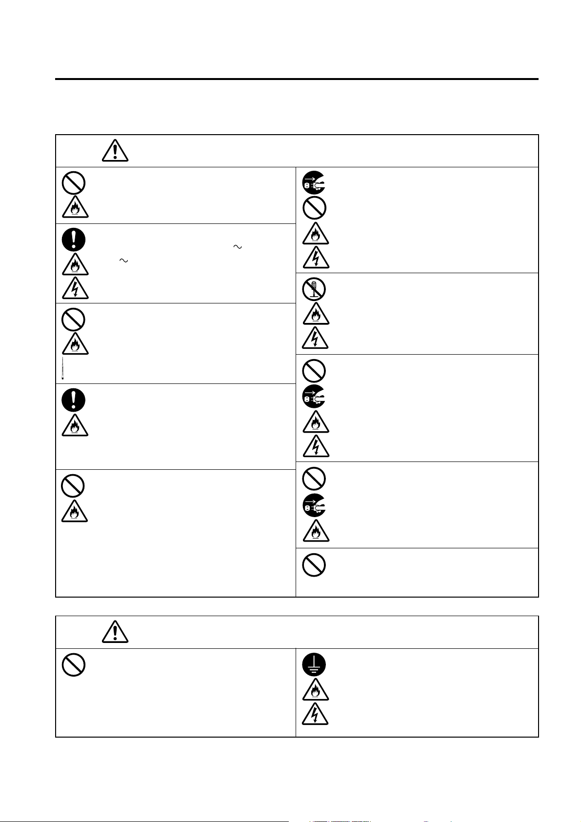
Safety Symbols
The following symbols are used in this manual to prevent accidents which may occur as result of incorrect
use of the instrument.
Denotes a sentence regarding safety warning or note.
Read the sentence carefully to ensure safe and correct use.
Denotes a sentence regarding safety precautions for risk of fire.
Read the sentence carefully to ensure safe and correct use.
Denotes a sentence regarding safety precautions for risk of electric shock.
Read the sentence carefully to ensure safe and correct use.
Denotes a prohibited operation.
The operation must never been performed.
Denotes an instruction.
The instruction must be strictly adhered to.
Denotes an instruction.
Disconnect the AC power cord from the AC outlet.
Denotes a prohibited operation.
The part must never be disassembled.
Denotes an instruction.
Connect the grounding terminal as instructed.
SIP/SOP Connections
• Accessories equipment connected the analog and digital interfaces must be certified to the respective
IEC standards (i.e. IEC 60950 for data processing equipment).
• Furthermore all configurations shall comply with the system standard IEC 61010-1. Everybody who
connects additional equipment to the signal input part or signal output part configures a electrical equipment for measurement system, and is therefore, responsible that the system complies with the requirements of the system standard (IEC 61010-1. If in doubt, consult the technical services department or your
local representative).
Notes on this Manual
• Copying or reproduction of all or any part of the contents of this manual without KONICA MlNOLTA’s
permission is strictly prohibited.
• The contents of this manual are subject to change without prior notice.
• Every effort has been made in the preparation of this manual to ensure the accuracy of its contents.
However, should you have any questions or find any errors, please contact a Konica Minolta authorized
service facility.
• KONICA MINOLTA will not accept any responsibility for consequences arising from the use of the
instrument.
Page 3
Safety Precautions
When using this hardware, the following points must be strictly observed to ensure correct and safe use.
After you have read this manual, keep it in a safe place so that it can be referred to easily whenever it is needed.
WARNING
Do not use the CA-Series in places where flammable or combustible gases (gasoline etc.) are
present. Doing so may cause a fire.
Always use the AC power cord supplied as a
standard accessory (for 100-120V or for 200240V ) with the CA-Series, and connect it to
an AC outlet . Failure to do so may damage the
CA-Series, causing a fire or electric shock.
Do not bend, twist or pull the AC power cord excessively. In addition, do not place heavy items
on the AC power cord, or damage or modify it in
any way. Doing so may cause damage to the AC
power cord, resulting in fire or electric shock.
If the CA-Series will not be used for a long time,
disconnect the AC power cord from the AC outlet. Accumulated dirt or water on the prongs of
the AC power cord’s plug may cause a fire. If there
is any dirt or water on the prongs of the AC power
cord’s plug, remove it.
The CA-Series should not be operated if dirt or
dust has entered through the vent holes. Doing so
may result in a fire. For periodic inspection, contact the nearest Konica Minolta authorized service
facility.
(Failure to adhere to the following points may result in death or
serious injury.)
When disconnecting the AC power cord’s plug,
always hold the plug and pull it to remove it. Never
pull the AC power cord itself. Doing so may damage the AC power cord, causing a fire or electric
shock. In addition, do not insert or disconnect the
AC power cord’s plug with wet hands. Doing so
may cause electric shock.
Do not disassemble or modify the CA-Series. Doing so may cause a fire or electric shock.
Take special care not to allow liquid or metal objects to enter the CA-Series. Doing so may cause a
fire or electric shock. Should liquid or metal objects enter the CA-Series, turn the power OFF immediately, disconnect the AC power cord from the
AC outlet, and contact the nearest Konica Minolta
authorized service facility.
The CA-Series should not be operated if it is damaged, or smoke or odd smells are detected. Doing
so may result in a fire. In such situations, turn the
power OFF immediately, disconnect the AC power
cord from the AC outlet, and contact the nearest
Konica Minolta authorized service facility.
Explanation Section
CAUTION
Do not place the instrument on an unstable or sloping surface. Doing so may result in its dropping
or overturning, causing injury. Take care not to
drop the instrument when carrying it.
(Failure to adhere to the following points may result in injury or
damage to the instrument or other property.)
Take care not to drop or overturn the CA-Series.
Failure to adhere to this precaution may result in
injury or your body being trapped.
Be sure to connect the AC power cord’s plug to an
AC outlet that has a protective grounding terminal. Also make sure that peripheral devices (e.g.
PC) are connected to AC outlets that have a protective grounding terminal. Failure to do so may
result in electric shocks.
1
Page 4

Foreword
Thank you for purchasing the CRT Color Analyzer CA-100 Plus. This instrument is designed for measurement of
color and luminance of various types of color displays including color CRT and PDP displays. Before using this
instrument, please read this manual thoroughly.
Notes on Use
● This instrument is designed for indoor use only, and should not be used outside.
● The instrument must never be disassembled as it is composed of precision electric components.
● Always use the rated power voltage. Connect the AC power cord (for 100-120V or for 200-240V) to an AC
outlet. Make sure that the voltage is within ±10% of the rated power voltage.
● This instrument is classified as Pollution Degree 2(equipment which may cause temporary electrical hazards
due to contamination or condensation, or products which are used in such an environment).
● This instrument is classified as Installation Category II (the specified commercial power voltage should be
used).
● Do not use the instrument at altitudes of higher than 2000m.
● The instrument must not be used if foreign matter such as water and metal objects enter it, doing so is very
dangerous.
● The instrument should not be used in certain environments, such as near a heater which will cause an excessive
rise in its temperature resulting in breakdown. Therefore it should not be used in such an environment. It should
be used in well-ventilated areas, and care should be taken not to allow the vent holes to become blocked.
● The instrument must not be used in areas subject to rapid changes of temperature, to avoid condensation.
● The instrument must not be used in areas where there is an excessive amount of dust or where the humidity is
excessively high.
● The instrument should be used at ambient temperatures of between 10 and 28˚C and humidity of 70 % relative
humidity or less. Be aware that to use it beyond this condition may make it degrade the performance.
● The instrument must not be exposed to excessive impact and vibrations.
● The AC power cord must not be pulled or bent excessively nor must excessive force be exerted on it. Doing so
may result in wire breakage.
● The AC power cord must not be connected to an AC line on which excessive noise is present.
● The instrument and personal computer must be grounded.
● If any irregularity or abnormality is found, turn OFF the power immediately, disconnect the AC power cord,
and refer to “Troubleshooting Guide” on page 111.
● Should the instrument break down, do not try to disassemble by yourself. Contact a Konica Minolta authorized
service facility.
●
Zero Calibration shall be made only after duration of 30 minutes or more passed since the power supply switch
is turned ON if the measuring display has brightness degrees of the following.
●
Measuring Probe CA-P02, CA-P05 0.5cd/m2 or less
●
High Luminance Measuring Probe CA-PH02,CA-PH05 1.0cd/m2 or less
Notes on Storage
● The instrument should be stored at temperatures of between 0 and 28˚C (70 % relative humidity or less and no
condensation) or at temperatures of between 28 and 40˚C (40 % relative humidity or less and no condensation).
It is recommended that it be stored with a drying agent (such as silica gel) at approximately room temperature.
To store it in areas subject to high temperatures and high humidity may make it degrade the performance.
● Take care not to allow condensation to form on the instrument during storage. In addition, pay attention to rapid
temperature changes during transportation to the storage area to prevent condensation.
2
Page 5

Cleaning
● If the instrument gets dirty, wipe it with a soft dry cloth. Never use solvents (e.g. benzene, thinner) or other
chemicals.
● If the optics of the probe gets dirty, wipe it with a soft dry cloth or lens cleaning paper.
● If it is not possible to remove dirt from the instrument, contact a Konica Minolta authorized service facility.
About This Manual
This manual is designed for those who possess basic knowledge of displays.
Before using this instrument, please read this manual thoroughly.
In some parts of the correction about Measuring Probe and High Luminance Measuring
Probe on this manual where type of probe is not specified, they are described as
"Measuring Probe".
A quick summary of measurement methods is given in “Measurement/Quick Guide” (pages 116 to 120), please
refer to it when you need a quick check.
For Those Who Want to Purchase Optional Accessories for this Instrument
This manual also explains how to use optional accessories available for this instrument.
If an explanation of how to use an optional accessory is given in this manual, its product name is also given.
Please read the explanation together with the manual supplied with the accessory.
<Example> ● Location of the explanation regarding 4-Probe Expansion Board CA-B04
When the optional 4-Probe Expansion Board CA-B04 is used
Explanation Section
3
Page 6
Contents
Safety Precautions ........................................................................................................................................................................ 1
Foreword ....................................................................................................................................................................................... 2
Notes on Use ................................................................................................................................................................................. 2
Notes on Storage ........................................................................................................................................................................... 2
Cleaning ........................................................................................................................................................................................ 3
About This Manual .......................................................................................................................................................................3
Manual Structure .......................................................................................................................................................................................... 6
Names and Functions of Parts .................................................................................................................................................................... 10
About Accessories ........................................................................................................................................................................................ 13
Standard Accessories .................................................................................................................................................................. 13
Optional Accessories .................................................................................................................................................................. 13
About CA-100 Compatible Mode .............................................................................................................................................................. 15
Function of Each Key ..................................................................................................................................................................................16
About Display .............................................................................................................................................................................................. 19
Installation/Connection ___________________________________________23
About Installation ........................................................................................................................................................................................25
About Connection ........................................................................................................................................................................................26
1. Connecting a Measuring Probe .............................................................................................................................................. 26
2. Installing the 4-Probe Expansion Board CA-B04 When the optional 4-Probe Expansion Board CA-B04 is used ..............27
3. Connecting the Power ............................................................................................................................................................. 28
4. Inputting the Vertical Synchronizing Signal ...........................................................................................................................28
Turning the Power ON ( | )/OFF (●) ......................................................................................................................................................... 29
1. Turning the Power ON ( | )/OFF (●) ...................................................................................................................................... 29
2. Instrument Status at Power-ON ..............................................................................................................................................30
3. About the change of Luminance Unit..................................................................................................................................... 32
Measurement Preparation _________________________________________33
Zero Calibration .......................................................................................................................................................................................... 34
1. Performing Zero Calibration .................................................................................................................................................. 34
2. Zero Calibration Check Method .............................................................................................................................................35
Selecting, Measurement Speed, SYNC Mode, Display Mode .................................................................................................................. 36
and the Number of Display Digits
1. Selecting the Measurement Speed ..........................................................................................................................................36
2. Selecting SYNC Mode ........................................................................................................................................................... 38
3. Selecting the Measurement Mode .......................................................................................................................................... 40
4. Selecting the Number of Display Digits ................................................................................................................................. 42
Selecting Probe No. When the optional 4-Probe Expansion Board CA-B04 is used ....................................................................... 43
Settings Section __________________________________________________45
Outline of the Settings Section ................................................................................................................................................................... 46
Before Making Each Setting ....................................................................................................................................................................... 48
1. About Memory Channels........................................................................................................................................................ 48
2. About the Target Color ........................................................................................................................................................... 49
User Calibration .......................................................................................................................................................................................... 50
1. About User Calibration ........................................................................................................................................................... 50
2. Performing White Calibration ................................................................................................................................................ 51
3. Performing Matrix Calibration ............................................................................................................................................... 53
4
Page 7

Analyzer Mode .............................................................................................................................................................................................57
1. About Analyzer Mode .............................................................................................................................................................57
2. Inputting the RGB Emission Characteristic for Analyzer Mode ............................................................................................ 58
Setting/Changing the Target Color ............................................................................................................................................................ 61
1. Setting/Changing the Target Color by Measurement ............................................................................................................. 62
2. Setting/changing the target color by entering values.............................................................................................................. 64
Other Settings .............................................................................................................................................................................................. 66
1. Setting an ID Name ................................................................................................................................................................ 66
2. Setting the Analog Display Range.......................................................................................................................................... 68
Settings Checking Method ..........................................................................................................................................................................72
1. Checking the Set Values ......................................................................................................................................................... 72
2. Checking the Probe Serial No. when Making Settings .......................................................................................................... 73
Measurement Section _____________________________________________75
Measurement ................................................................................................................................................................................................ 76
1. Performing Measurement ....................................................................................................................................................... 76
2. Holding the Measured Values .................................................................................................................................................77
3. Displaying the Measured Values ............................................................................................................................................ 78
White Balance Adjustment in Analyzer Mode ..........................................................................................................................................80
Communications Section __________________________________________83
Communicating with PC ............................................................................................................................................................................. 84
1. Communicating with PC via RS-232C ................................................................................................................................... 84
2. Selecting the RS-232C Baud Rate .......................................................................................................................................... 85
3. Communicating with PC via USB .......................................................................................................................................... 86
4. Remote Measurement .............................................................................................................................................................86
5. Communication Method for CA-100 Compatible (RS-232C) ............................................................................................... 87
Communication Format .............................................................................................................................................................................. 90
1. Input Command Table (PC ➔ Instrument) ............................................................................................................................. 90
2. OUTPUT DATA (PC ➔ Instrument) ......................................................................................................................................94
Explanation Section ______________________________________________99
Measuring Principle .................................................................................................................................................................................. 100
1. Measuring Principle .............................................................................................................................................................. 100
2. About T∆uvLv ...................................................................................................................................................................... 101
3. Principle of User Calibration ................................................................................................................................................102
4. Principle of Analyzer Mode.................................................................................................................................................. 103
Maintenance ...............................................................................................................................................................................................105
1. Cleaning the Instrument ....................................................................................................................................................... 105
2. Storing the Instrument .......................................................................................................................................................... 105
Dimension Diagram ................................................................................................................................................................................... 106
Error Messages .......................................................................................................................................................................................... 107
Troubleshooting Guide .............................................................................................................................................................................. 111
Specifications ............................................................................................................................................................................................. 114
Measurement/Quick Guide ....................................................................................................................................................................... 116
5
Page 8
Manual Structure
This manual is divided into sections as shown below according to the contents.
This section explains how to install the instrument, connect AC power, turn ON/OFF the power, and
input the vertical synchronizing signal.
About Installation
Provides operating environmental conditions for the instrument and notes on installation.
About Connection
Explains how to connect measuring probes and connect the power cord.
(Also explains installation method for the optional accessory “4-Probe Expansion Board”.)
* Before turning on the power: Refer to pages 84 to 86 if you are going to communicate the instru-
ment with the PC via RS-232C or USB.
Installation/Connection P. 23-32
Turning the Power ON/OFF
Explains how to turn ON/OFF the power.
● The Preparation/Setting/Measurement section explains the procedure up to measurement.
The Measurement Preparation section explains preparations (instrument setting, zero calibration) that
are required prior to measurement.
Zero Calibration
Explains the zero point adjustment method.
(Measurement cannot be performed if zero calibration is not completed.)
Page 25
Page 26
Page 29
Page 34
Selecting, Masurement Speed, SYNC Mode, Display Mode and the Number of Display Digits
Explains how to select SYNC mode, that selects measurement time according to the display’s vertical scanning frequency,
as well as explaining how to select measurement mode and the number of display digits.
Measurement Preparation P. 33-44
To the Setting section P. 45-74
When the optional 4-Probe Expansion Board CA-B04 is used
Selecting Probe No.
Explains how to select the measuring probe whose measured value is to be displayed.
* Go to the Measurement section if you are going to perform measurement using
Konica Minolta’s calibration standard and are not going to use analog display.
6
Page 36
Page 43
Page 9

This section explains settings that must be made according to measurement method.
The setting method varies with measurement method.
From the Measurement Preparation section
Outline of the Settings Section
Explains measurement method types and settings that must be made.
(Check what settings you need to make.)
Page 46
Settings Section P. 45-74
Before Making Each Setting
Gives detailed explanations on memory channels common to each setting and target colors.
When performing measurement using
Konica Minolta’s calibration standard
Setting/Changing the Target Color *1
Explains how to set/change the target color.
1. Setting/Changing the Target
Color by Measurement
2. Setting/Changing the Target
Color by Entering Values
When performing measurement using
user calibration
User Calibration
Gives detailed explanation of user
calibration and explains its execution
method.
(Target color is also set at this time.)
Page 48
When performing measurement in analyzer mode
Analyzer Mode
Gives detailed explanation of analyzer mode and explains how to input the display’s RGB emission characteristic for Analyzer Mode.
(Target color is also set at this time.)
P. 6 1 P. 50 P. 57
•To set an ID name:
“Setting an ID Name”
(Page 66) *2
•To use the analog display
function:
“Setting the Analog
Display Range” (Page
68) *3
To the Measurement section
P. 75-82
•To change the target color after user
calibration:
“Setting/Changing the Target Color”
(Page 61) *1
Other Settings
Explains how to set an ID name *2
and analog display range *3.
P. 6 6 P. 7 2
7
•To change the target color
after inputting the display’s
RGB emission characteristic:
“Setting/Changing the Target
Color” (Page 61) *1
Settings Checking Method
Explains how to check the set values
and check the probe serial no. used
when the values are set.
Page 10
This section explains measuring methods.
From the Settings section
Measurement Section P. 75-82
Measurement
Explains measuring methods, how to hold the measured values and how to read them.
White Balance Adjustment in Analyzer Mode
Explains how to adjust white balance.
Page 76
Page 80
This section explains communication with PC via RS-232C or USB.
It is designed for those who possess basic knowledge of controlling the instrument from the PC via RS232C and know the basic operating methods (Measurement Preparation and Measurement sections).
Communicating with PC via RS-232C
Explains how to connect the RS-232C cable and select the RS-232C baud rate to enable two-way communication with PC
via RS-232C.
Page 84
Communications Section P. 83-98
Communicating with PC via USB
Explains how to connect the USB cable to enable communication with PC via USB.
Remote Measurement
Explains how to perform measurement from the PC remotely.
Communication Method
Explains how to input communication commands.
Communication Format
Explains the format of commands that are input to the instrument and that of data which is output from the instrument.
Page 86
Page 86
Page 87
Page 90
8
Page 11

This section explains the following items.
Explanation Section P. 99-121
Measuring Principle
Maintenance
Dimension Diagram
Error Messages
Please read when an error message appears in the LCD display section.
Troubleshooting Guide
Please read when the instrument does not function correctly.
Page 100
Page 105
Page 106
Page 107
Page 111
Specifications
Measurement/Quick Guide
Provides an outline of operations explained in the previous sections (Measurement Preparation - Measurement).
Page 114
Page 116
Explanation Section
9
Page 12

Names and Functions of Parts
Main Body
<Front>
4 Measurement mode
indications
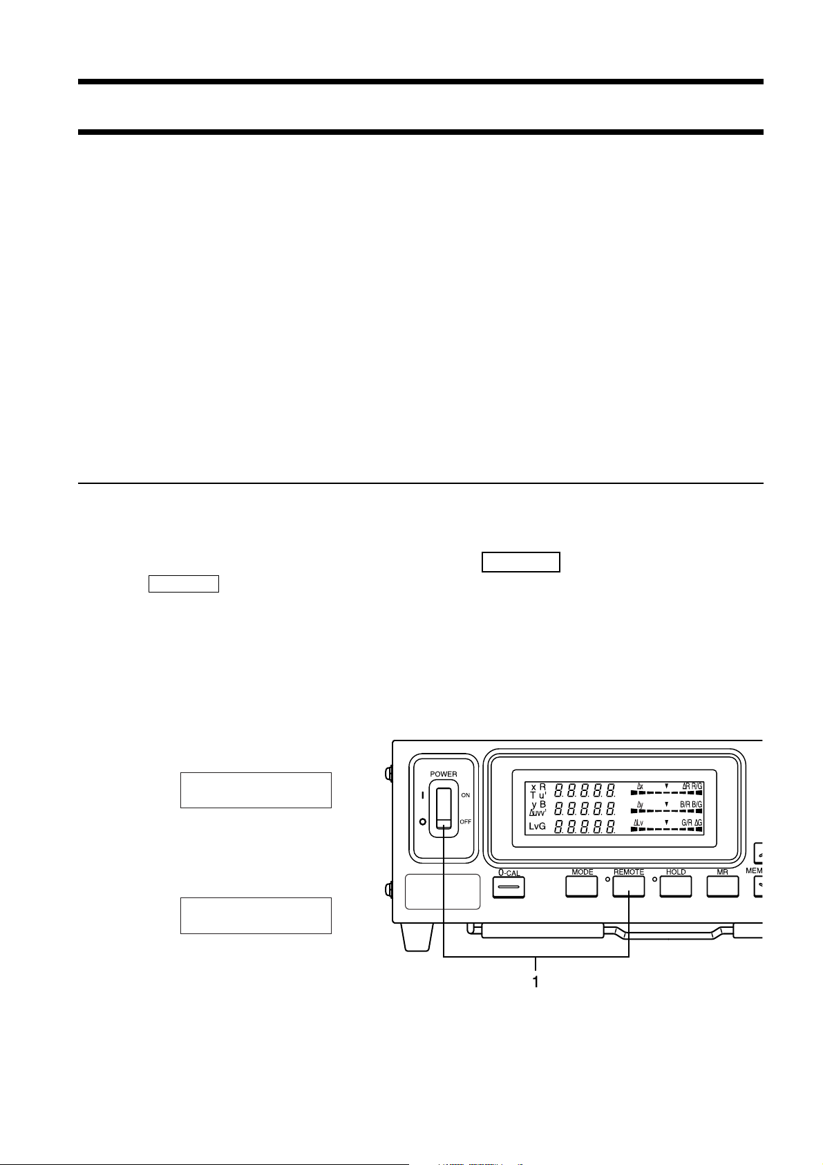
1 POWER switch
2 Digital display
6 HOLD LED
7 REMOTE LED
9 Tilt stand
5 LCD display3 Analog display
8 Key panel
<Rear>
10
Probe connector [P1]
15
4-Probe Expansion
Board slot
11
USB connector
12
RS-232C connector
13
Vertical synchronizing signal input terminal
14
AC power connector
10
Page 13

Main Body
<Front>
1 POWER switch........................................ • Used to turn ON and OFF the power to the instrument. (Page 29)
2 Digital display section ............................. • Displays the measured values.
3 Analog display section ............................ • Displays the difference (%) between the measured value and the
target color or the difference (%) between measured values.
• The range for each dot can be set between 0.1 and 99%. (Page 68)
4 Measurement mode indications ............... • Displays the measurement mode in which the measured values
are displayed. (Page 40)
• The table below shows the relationship between measurement
modes and data displayed in the digital display section 2 and
analog display section 3.
Measurement mode
xyLv mode x, y, Lv ∆x, ∆y, ∆Lv
T∆uvLv mode T, ∆uv, Lv ∆x, ∆y, ∆Lv
Analyzer mode (G reference) R, B, G R/G, B/G, ∆G
Analyzer mode (R reference) R, B, G ∆R, B/G, G/R
u'v'Lv mode u', v', Lv ∆x, ∆y, ∆Lv
XYZ mode XYZ ∆x, ∆y, ∆Lv
5 LCD display ............................................ • Displays the memory channel, probe no., ID name, warning and
6 HOLD LED ............................................. • Lights up during hold.
7 REMOTE LED ........................................ • Lights up when the instrument is ready for communication with
8 Key panel ................................................. • Used to select/set probe no., SYNC mode, measurement speed,
9 Tilt stand
2
Digital display
settings.
the PC via RS-232C or USB interface.
analog display range and ID name, as well as entering values.
(Page 17)
3
Analog display
<Rear>
10
Probe connector [P1] ............................... • Used to connect a measuring probe. (Page 26)
11
USB connector ........................................ • USB interface for communication with the PC etc. (Page 86)
12
RS-232C connector ................................. • RS-232C compatible interface for communication with the PC
etc. (Page 84)
13
Vertical synchronizing signal .................. • Input the display’s vertical synchronizing signal into this terminal
input terminal when performing measurement in EXT SYNC mode. (Page 28)
SYNC: Terminal shall tread as class 3 accordance with IEC
10101-1 Annex-H.
14
AC power connector ................................. • Connect the AC power cord to this connector to supply power to
the instrument. (Page 28)
• The rating is AC100-240V, 50-60 Hz, 50VA.
15
4-Probe Expansion Board slot ................. • Used to install the optional 4-Probe Expansion Board (CA-B04).
(Page 27)
Chapter_Title
11
Page 14
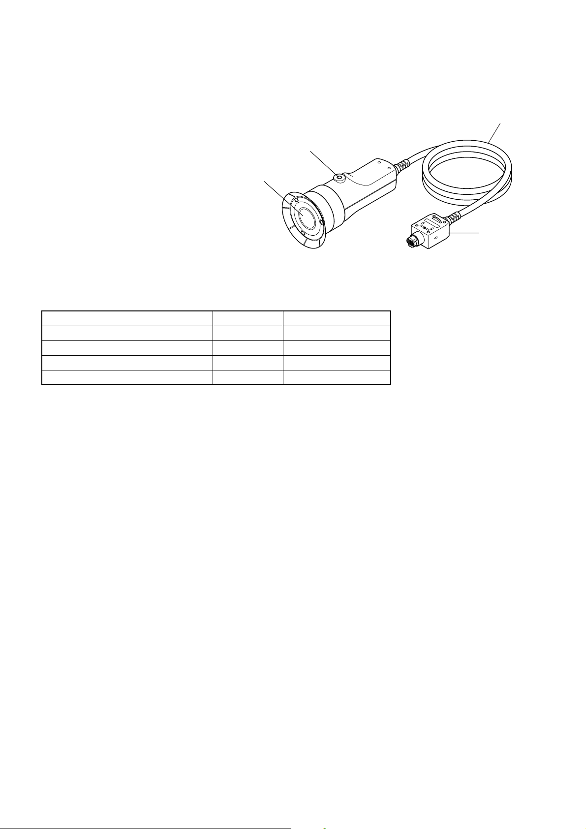
Measuring Probe CA-P02(2m) /CA-P05(5m)
High luminance Measuring Probe CA-PH02(2m) /CA-PH05(5m)
Connecting cord
(CA-P02/PH02: 2 m/6.6 ft)
2 Screw hole
ISO screw 5 mm
(depth: 6 mm)
1 Receptor area
Measuring is done with a probe in intimate contact with the surface of display in the measuring part of this equipment. There are 2 m and 5 m long cord. There are 2 types of Measuring Probe.
Probe model Cord length Product name
Measuring Probe 2m CA-P02
Measuring Probe 5m CA-P05(option)
Hith luminance Measuring Probe 2m CA-PH02
Hith luminance Measuring Probe 5m CA-PH05(option)
(CA-P05/PH05: 5 m/6.6 ft)
3 Plug
∗ Either of the accessories described above is included.
1 Receptor ................................................... • Place this receptor with the display’s screen surface and perform
measurement.
2 Screw hole ............................................... • Used to secure the probe to a jig etc.
3 Plug .......................................................... • Connect this plug to the probe connector on the main unit or that
on the optional 4-Probe Expansion Board (CA-B04).
1212
Page 15

About Accessories
Standard Accessories
● AC power cord (For 100-120V or 200-240 V)
Connect this cord to the AC power connector to supply power to
the instrument.
For a description of how to connect, refer to page 28.
(For 100-120 V)
(For 200-240 V)
● Measuring probe
● Measuring probe holder CA-A11
Provided for storage of a measuring probe.
Mount method
The holder must be mounted on the side of the instrument with
two screws.
Measuring probe holder
mount hole
● Color analyzer PC software CA-SDK
● Instruction manual
Read this manual before operating the instrument.
Installation/Connection
Measuring
probe
Measuring
probe holder
Measuring
probe holder
Screws on
main body
Optional Accessories
● Measuring probe CA-P02/CA-P05
● High luminance Measuring probe CA-PH02/CA-PH05 (Page 12)
Connect the probes to the main body or the probe connectors on the
4-Probe Expansion Board CA-B04 before measurement.
Location of the explanation
Connecting method: Page 26
Measuring method: Measurement Preparation,
Setting, Measurement sections
1313
Page 16

● 4-Probe Expansion Board CA-B04
Connect measuring probes (CA-P02/CA-P05,CA-PH02/CA-PH05)
to this board, to allow simultaneous measurement of the colors at up
to 5 points on the display’s surface.It is possible to install Measuring
Probes of all types to be coresident.
Location of the explanation
Installation method: Page 27
Measuring method: Measurement Preparation, Setting, Measure-
ment sections
Connector
[P2]
Probe connector
Grip
[P3]
[P4]
[P5]
1414
Page 17
About CA-100 Compatible Mode
This instrument offers two modes: “CA-100 compatible mode”, that provides data compatibility with measured
data taken by the CRT color analyzer CA-100 and allows communications via RS-232C, and “CA-200” mode, that
allows use of the CA-SDK software supplied with this instrument. “CA-100 compatible mode” has been set prior
to shipment from the factory.
If you have established a CA-100-based communication environment and are going to introduce this instrument,
use “CA-100 compatible mode”.
<CA-100 Compatible Mode>
● Allows control of the instrument using RS-232C commands
same as CA-100.
[Switching Communication Mode]
Switch the mode from CA-100 compatible mode to CA-200 mode or vice versa.
Once a mode is selected by this method, it will remain effective until it is changed by this method.
Installation/Connection
Set the POWER switch to ON (|) while pressing the REMOTE key.
The REMOTE key must be kept held down for more than two seconds after the power is turned ON.
The mode will switch and the instrument will start up.
The communication mode can be switched from CA-100 compatible mode to CA-200 mode or vice versa
as shown below.
CA-200 mode → CA-100 compatible mode
Display
REMOTE
CA-100 MODE
CA-100 compatible mode → CA-200 mode
Display
REMOTE
CA-200 MODE
1515
Page 18

Function of Each Key
Key Panel
1 0-CAL key ............................................. • Performs zero calibration. Before pressing this key, make sure that
the measuring probe is blocked from light. (Page 34)
2 Mode key ............................................... • Select measurement mode. (Page 40)
Measurement mode changes in the following order.
Analyzer mode
xyLv→T∆uvLv→RBG (R/G, B/G, ∆G)→RBG (∆R, B/G, G/R)→
u'v'Lv→XYZ →xyLv
3 MR key .................................................. • Displays the specified target color in the LCD display section. (Page
73) (For long depression of this key, refer to page 18.)
4 HOLD key ............................................. • Holds the display of the measured value. (The HOLD LED will
light up.)
• Pressing this key while the HOLD LED is lit will cancel hold mode.
(The HOLD LED will go out.)
16
Page 19

5 REMOTE key ....................................... • Sets the instrument in remote mode (i.e. communication with the
PC is possible via RS-232C or USB).
(The REMOTE LED will light up. See page 86.)
•Pressing this key while the REMOTE key is lit will cancel remote
mode. (The REMOTE LED will go out.)
(Note) Remote mode should not be activated unless you are going to communi-
cate with the PC.
Otherwise, the other keys will be inoperative.
6 MEMORY CH key ........................ • Used to select a memory channel (CH00 to 99).
key Pressing the key will switch memory channel in the order
“00→01→02
Pressing the
“00→99→98
The memory channel switches from one to another each time the
key is pressed, and switches continuously if the key is left held
down.
…
…
98→99→00…”.
key will switch memory channel in the order
01→00→99…”.
<Keys on Key Panel>
1 Number-key ( ~ , ).................. • Used to enter calibration data for user calibration (page 50), target
color (page 61), ID name (page 66) and analog display range (page
68).
2 ALPHA key ( ) ................................... • Used to enter alphabets. This key enables you to use the number-
key as alphabet keys. Pressing this key again will restore the original function of the ten-key.
3 Alphabet keys ( ~ , )................ • Used to enter alphabets for the ID name.
4 MENU key ( ) ..................................... • Switches the LCD display section to the menu selection screen.
Pressing this key again will restore the original function of the LCD
display section.
5 CAL key ( ) ........................................ Normal Screen
• When CH00 is selected as the memory channel
You can enter a value for the target color. (Page 64)
•When thememory channel other than CH00 is selected as the memory
channel
You can set CA-100 for input of WRGBdata for user calibration.
(Page 50)
• When an analyzer measurement mode is selected
You can set CA-100 for input of RGB emission characteristic and
target color (W). (Page 58)
Menu Selection Screen
•Pressing the
to switch as follows.
PROBE selection → SYNC selection → ID Name input → RANGE
setting → Measurement Speed selection → Number of Digits setting → RS232C Baud Rate selection → PROBE selection
key in the menu selection screen causes the screen
Installation/Connection
17
Page 20

6 Cursor key ( ) ..................................... • Used to switch from one option to another in the PROBE, SYNC,
Measurement Speed, Number of Digits, and RS232C baud rate
screens, which are opened from the menu selection screen.
7 ENTER key ( ) ................................... • Used to confirm each setting/selection you have made.
8 White, Red, Green, .................................. • Used to set RGB emission characteristics of the display.
Blue keys (
)
1 Holding down the key ....................... Locks all the keys except for the 0-CAL key. Holding down this
for two seconds or more key again for two seconds or more will unlock the keys.
(Whistling sound.)
2 Holding down the key .......................
for five seconds or more
(Bleeping sound. A whistling sound
is heard when the setting is saved.)
3 Holding down the MR key .................... When xyLv, T
for two to four seconds Displays serial number of the probe in use at the time calibration to
(Bleeping sound.) a user selected reference was performed and the target color were
4 Holding down the MR key .................... The unit of luminance will be displayed. (cd/m
for four seconds or more
(Bleep sounds two seconds later and
then four seconds later.)
Stores the current settings (probe, SYNC, memory channel, measurement
mode) to the instrument. The settings will be effective when the power
turned on next time.
∆∆
∆uvLv or XYZ measurement mode is selected
∆∆
set. (Page 73)
When an analyzer mode is selected
Displays serial number of the probe in use at the time RGB emission
characteristics of the display and the target color (W) were set. (Page
73)
2
or fL)
is
5 Holding down the REMOTE key ......... The mode will switch to CA-100 compatible mode and CA-200
for two seconds or more mode alternately. (Page 15)
when turning on the power
1818
Page 21
About Display
1 Measurement mode
indications
CH00 EXT P1
[MINOLTA ]
2Digital display section 3 Analog display section
* This shows when the entire display area is lit. (The LCD display section is not shown.)
4 LCD display section:
1 Measurement mode ................................. Displays the measurement mode in which the measured values are
displayed.
Measurement mode switches from one to another as shown below
each time the MODE key is pressed. (Page 40)
Analyzer mode
xyLv→T∆uvLv→RBG (R/G, B/G, ∆G)→RBG (∆R, B/G, G/R)→
u'v'Lv→XYZ →xyLv
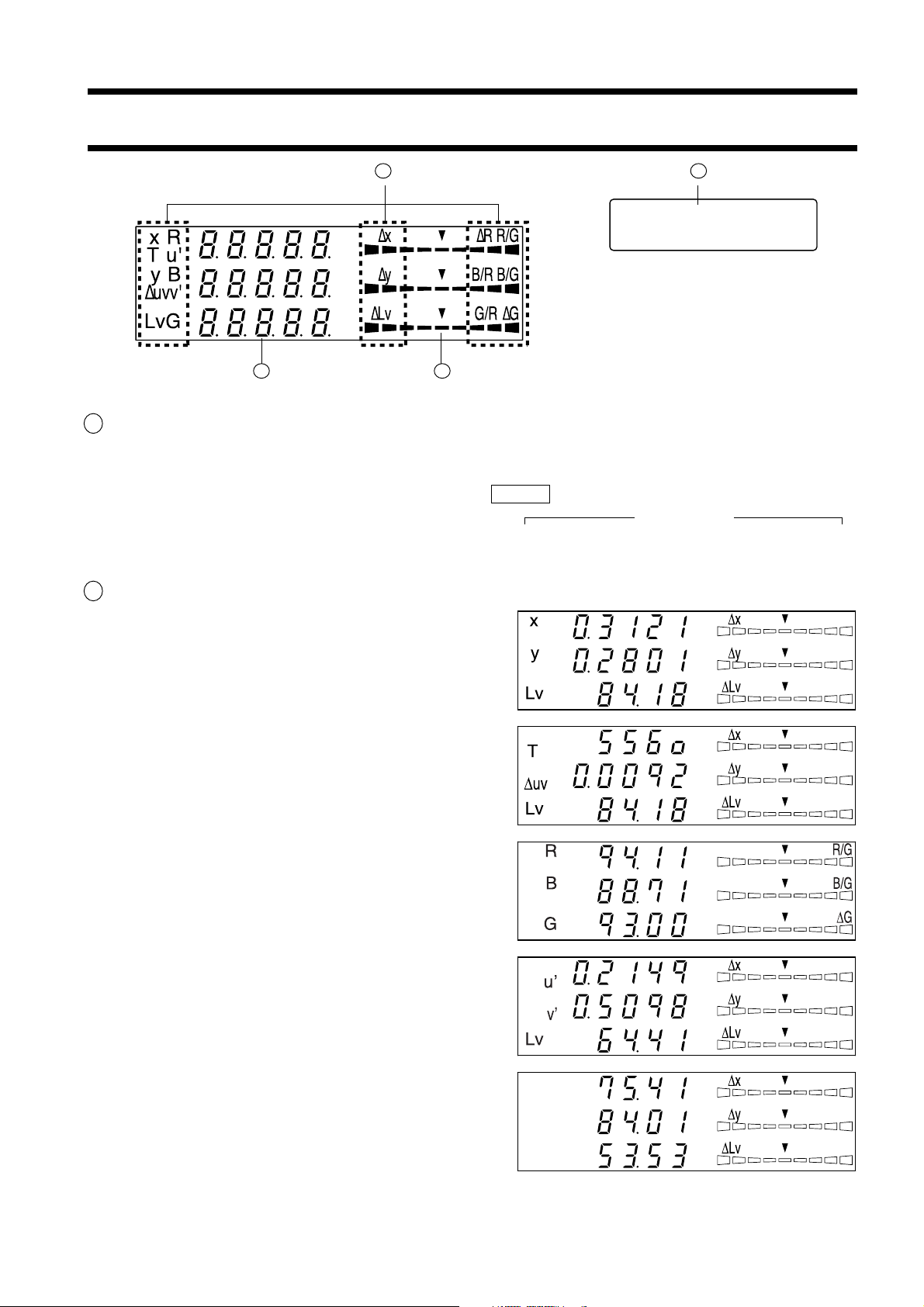
2 Digital display section ............................. Displays the measured values.
● When xyLv measurement mode is selected
x, y and Lv are displayed.
Installation/Connection
● When T∆uvLv measurement mode is selected
T, ∆uv and Lv are displayed.
T (correlated color temperature) is displayed in three
significant digits.
● When an analyzer measurement mode is selected
R, B and G are displayed. R-reference and G-reference
are available. (The same contents are displayed in the
digital display area, whether R-reference or G-reference.)
● When u'v'Lv measurement mode is selected
u', v' and Lv are displayed.
● When XYZ measurement mode is selected
X, Y and Z are displayed. (X, Y and Z from top to bottom)
1919
Page 22

3 Analog display section ............................ Displays the difference (%) between the measured value and the tar-
get color or the difference (%) between measured values.
The range for each dot can be set between 0.1 and 99%. (Page 68)
The range has been set to 10% prior to factory shipment.
● When xylv, T∆uvLv, u'v'Lv or XYZ measurement
mode is selected
∆x, ∆y and ∆Lv are displayed.
● When an analyzer measurement mode is selected
For G-reference R/G, B/G and ∆G are displayed.
For R-reference ∆R, B/R and G/R are displayed.
-
n×8%
or lower
Red Green Red
Below ±n%
Below ±n×2%
Below ±n×4%
Below ±n×8%
+n×8% or
higher
4 LCD display section ................................ Displays the memory channel, probe no., ID name, warning and set-
tings.
In case of error, an error message will appear.
(For a description of what to do in case of error, refer to page 107.)
Displays the currently selected SYNC mode. (NTSC,
PAL, EXT, UNIV, INT) (Page 38)
Displays the currently selected measurement speed.
(A.F.S) (Page 36)
Displays the calibration mode for the currently selected memory channel. (d.a.m) (Page 56)
Probe no. (Page 43)
Memory channel
(Page 48)
CH00 EXT Ad P1H
[MINOLTA ]
H will be displayed for High Luminance Measuring
Probe(CA-PH02/05). For Measuring Probe(CA-P02/
05) nothing will be displayed.
ID name display area (Page 66)
20
Page 23

<Out of Measurement Range>
● When the measurement range is exceeded Digital display : “– – –”
Analog display : Not lit
LCD display : “OVER”
● When Lv (luminance) is below 0.05 cd/m
2
Digital display : blinking
(white calibration equivalent to Analog display : blinking
Konica Minolta's calibration standard) : Measurement mode : blinking
● When T∆uvLv measurement mode Digital display : “– – –”
is selected and T and ∆uv are out of (T and ∆uv)
the display range
Installation/Connection
21
Page 24

22
Page 25

Installation/Connection
This section explains how to install the instrument, connect
AC power, turn ON/OFF the power, and input the vertical synchronizing signal.
About Installation
Provides operating environmental conditions for the instrument and notes
on installation.
About Connection
Explains how to connect measuring probes and connect the power cord.
(It also explains installation method of the optional 4-Probe Expansion Board.)
* Before turning on the power : Refer to pages 84 to 86 if you are going to communicate the instrument with the
PC via RS-232C or USB.
Page 25
Page 26
Installation/Connection
Turning the Power ON/OFF
Explains how to turn ON/OFF the power.
Page 29
23
Page 26

SAFETY WARNING
(Failure to adhere to the following points may result in death or serious injury.)
Do not use the instrument in areas where flammable or combustible gases (gasoline fumes etc.)
are present.
Doing so may result in a fire.
If dust has entered through the vents and collected
inside the instrument, do not use the instrument.
Doing so may result in a fire.
For periodic inspection, contact a Konica Minolta
authorized service facility.
Always use the AC power cord supplied as a standard accessory with the instrument, and connect
it to an AC outlet (100-240V, 50-60 Hz).
Connecting to a voltage other than that specified
may result in damage to the instrument, fire or
electric shock.
• Do not bend, twist or pull the AC power cord
excessively.
•Do not place heavy items on the AC power cord
or scratch it.
• Do not modify the AC power cord.
Doing so may damage it, resulting in fire or electric shock.
When disconnecting the AC power cord’s plug, always hold the plug and pull it to remove it. Never
pull the AC power cord itself as it may be damaged, resulting in fire or electric shock.
Also do not insert or disconnect the AC power cord’s
plug with wet hands. Doing so may cause electric
shock.
If you are not going to use the instrument for a long
time, disconnect the AC power cord from the AC
outlet. Dirt or water may accumulate on the prongs
of the AC power cord’s plug and it may cause a
fire. If there is any dirt or water on the prongs, it
must be removed.
SAFETY PRECAUTIONS
• Do not place the instrument on an unstable or
sloping surface.
•When you carry the product, take care not to let
it drop.
Doing so may result in its dropping or overturning, causing injury.
(Failure to adhere to the following points
may result in injury or damage to the instrument or other property.)
Be sure to connect the AC power cord’s plug to an
AC outlet that has a protective grounding terminal.
Also make sure that peripheral devices (e.g. PC)
are connected to AC outlets that have a protective
grounding terminal. Failure to do so may result in
electric shocks.
2424
Page 27

About Installation
The operating environmental requirements are given in the “Specifications” of this manual. The instrument must
be installed in a place that completely meets these requirements. (Page 114-115)
<Notes on Installation>
● Using the instrument in direct sunshine in midsummer or near a heater will cause a rapid rise in its temperature
resulting in breakdown.
Special care must be taken when handling the instrument in such an environment. In addition, take care not to
allow the vents to become blocked. Do not use the instrument in poorly ventilated areas.
● Do not use the instrument in a place where the temperature changes rapidly, since measured values will be
incorrect.
● The instrument must not be used in areas where there is an excessive amount of dust or where the humidity is
excessively high.
● The instrument must not be used if foreign matter such as water and metal objects enter it, doing so is very
dangerous.
● The AC power cord must not be pulled or bent excessively nor must excessive force be exerted on it. Doing so
may result in wire breakage.
● The AC power cord must not be connected to an AC line on which excessive noise is present.
● If any irregularity or abnormality is found, turn OFF the power immediately, disconnect the AC power cord,
and refer to “Troubleshooting Guide” on page 111.
Installation/Connection
2525
Page 28

About Connection
1. Connecting a Measuring Probe
Before setting the POWER switch to ON, a measuring probe must be connected to the probe connector [P1] on the
instrument.
[Connecting Method]
1. Set the POWER switch to OFF (“O” position).
2. Insert the probe’s plug into the probe connector
[P1], with the probe serial no. facing down.
3. Check that the plug is inserted all the way and
connected firmly
• When disconnecting the measuring probe, set the POWER
switch to OFF first, and pull the probe by holding the plug.
Never pull the probe by its cord.
Probe connector [P1]
<Notes when Connecting the Probe>
● Never connect or remove the measuring probe while the POWER
switch is ON.
● When connecting/disconnecting the measuring probe, always hold
the plug and connect/disconnect it. In addition, do not pull or bend
the cord excessively or exert excessive force on it. Doing so may
result in wire breakage.
● The Measuring Luminance Range will vary according to the type
of Measuring Probe.
● When measurement is implemented, the same Measuring Probe
to be used for the User Calibration is necessary. If measurement
is carried out by connecting the different Measuring Probe, error
message E1 will be displayed.
26
Page 29

2. Installing the 4-Probe Expansion Board CA-B04
When the optional 4-Probe Expansion Board CA-B04 is used
Installing the optional 4-Probe Expansion Board CA-B04 in the instrument allows simultaneous measurement of
the colors at up to 5 points on the display’s surface. Install the expansion board as shown below.
[Installation Method]
1. Remove the cover of the 4-Probe Expansion Board slot.
1 Set the POWER switch on the instrument to OFF.
2 Remove the two screws from the slot cover, and re-
move the cover.
2. Install the 4-Probe Expansion Board.
1 Place the 4-Probe Expansion Board along the right-
and left-side guides in the slot.
2 Push the board all the way and make sure that the
board is connected properly.
3 Secure the board with the two screws that were re-
moved previously.
• Repeatability of the measurement value becomes
worse when the fixation by the screw is incomplete.
• To remove the board, remove the two screws first,
then hold the grip of the board and pull it out. After
the board is removed, attach the cover to the slot.
Guide
Installation/Connection
<Notes on Installation>
● When installing/removing the 4-Probe Expansion Board,
always set the POWER switch to OFF and pull the AC
power cord from the AC outlet first.
● Do not touch the connectors (gold plated parts) or ICs on the 4-Probe Expansion Board with your hands. If oil
or similar matter adheres to the connectors, wipe them with a soft, dry cloth.
<Connecting Measuring Probes>
The following four types of measuring probes can be connected.
Probe model Product number and cord length
Measuring Probe CA-P02: 2 m/CA-P05: 5 m
High luminance Measuring Probe
A total of five probes can be connected. When connecting two
or more probes, always make sure that one of them is connected to the probe connector [P1].
Connect necessary number of probes to the probe connectors [P2] to [P5] on the 4-Probe Expansion Board. You do
not have to connect any probes to those connectors ([P2] to [P5]). Probes can be connected to any connectors ([P2]
to [P5]).
The Measuring Luminance Range will vary according to the type of Measuring Probe.
4 types of optionally available Measuring Probes can be connected.
As the Measuring Luminance Range of Measuring Probe will vary according to the type, please install one that is
fit for your use. Also, different types can be coresident.
CA-PH02: 2 m/CA-PH05: 5 m
● The connecting method for connectors [P2] to [P5] is the same as that for [P1]. (Refer to page 26.)
Notes when connecting probes: Probe connectors on the 4-Probe Expansion Board where no probe is connected must be capped.
27
Page 30

3. Connecting the Power
Power voltage range for the instrument — 100 to 240V
[Connection Method]
1. Set the POWER switch to OFF (“O” posi-
Main body
tion).
2. Connect the AC power cord’s connector to
2
the AC power connector on the instrument.
The AC power cord must be connected as shown in the
figure.
3. Insert the AC power cord’s plug to an AC outlet.
AC power connector
AC power cord
3
To an AC outlet
<Notes on Power Connection>
● Never connect or remove the AC power cord while the POWER switch is ON.
● When connecting/disconnecting the AC power cord, always hold the plug and connect/disconnect it. In addi-
tion, do not pull or bend the cord excessively or exert excessive force on it. Doing so may result in wire
breakage.
● Be sure to connect the AC power cord's plug to an AC outlet that has a protective grounding terminal.
4. Inputting the Vertical Synchronizing Signal
The vertical synchronizing signal from the display can be input to the instrument to allow synchronous measurement (when EXT SYNC mode is selected).
However, if another SYNC mode is selected, it is not necessary to input the vertical synchronizing signal.
Connect the BNC cable of the vertical synchronizing signal (frequency: 40 to 200 Hz) used for the display to the
connector on the rear panel of the instrument as shown below. Before connecting, make sure that the power to both
the instrument and display is turned OFF.
Circuit diagram
Vertical synchronizing
signal input terminal
2
1
BNC connector
Connector type: BNC
C-MOS logic level
Input the vertical
synchronizing signal.
(40 to 200 Hz)
74HC14
(operated with 5V)
* To synchronize measurement with the display’s vertical synchronizing signal, EXT must be selected as the SYNC mode. For details, refer
to page 36.
2828
Page 31

Turning the Power ON ( | )/OFF (●)
1. Turning the Power ON ( |
Before setting the POWER switch to ON ( | ), prepare the following.
)/OFF (●
)
1. Connect a measuring probe to the probe connector [P1]. (Page 26)
• To synchronize measurement with the ... 1
display’s vertical synchronizing signal (Page 28)
(EXT is selected as the SYNC mode)
• To perform measurement .......................
with two or more measuring probes
• To communicate with the PC .................
via RS-232C
• To communicate with the PC via USB ...
Input the vertical synchronizing signal that is used for the display.
1
Install the 4-Probe Expansion Board CA-B04 (option) in the
in
strument. (Page 27)
2 Connect necessary number of probes to the probe connec-
tors [P2] to [P5]. (Pages 26 and 27)
1
Connect the instrument’s RS-232C connector to the PC. (Page 84)
1
Connect the instrument’s USB connector to the PC. (Page 86)
2. Connect the AC power cord to an AC outlet. (Page 28)
[Turning the Power ON ( | )]
Set the POWER switch to ON ( | ).
If the instrument is connected to external equipment,
set the instrument’s POWER switch to ON ( | ) first,
then turn ON ( | ) the power to the external equipment.
CA-200 MODE
PROBE [P1]
NO.XXXXXXXX
Installation/Connection
Either “CA-200
MODE” or “CA-100
MODE” is displayed
(see page 13).
Probe serial no.
DARKEN PROBE
PUSH 0-CAL KEY
[Turning the Power OFF (● )]
If the instrument is connected to external equipment, turn OFF (●) the power to the external equipment
first, then set the instrument’s POWER switch to OFF (●).
<Error Messages in LCD Display Section>
● “SET MAIN PROBE” (After the POWER switch is set to ON ( | ))
• Cause 1 : The measuring probe is not connected to the probe con-
nector [P1] properly.
• Action 1: Set the POWER switch to OFF (●), then connect the measuring probe to the probe connector
[P1] properly. (Before connecting/disconnecting the measuring probe, make sure that the
POWER switch is set to OFF (●).)
● “PROBE ERROR”
• Cause 1 : A measuring probe was connected or disconnected while
the POWER switch was ON ( | ).
• Action 1: Set the POWER switch to OFF (●) first, connect necessary measuring probes, then set the
POWER switch to ON ( | ). (Before connecting/disconnecting the measuring probe, make sure
that the POWER switch is set to OFF (●).)
2929
…
For other error messages, refer to page 107.
SET MAIN PROBE
PROBE ERROR
Page 32

2. Instrument Status at Power-ON
The instrument has been set prior to factory shipment so that it will be set as follows when the POWER switch is
set to ON.
1 Measurement mode Page 40 xyLv mode
2 Memory channel no. Page 48 CH00
3 Target color Page 64 x = 0.3127 y = 0.3293 Lv = 40.00 (cd/m2)
4 PROBE Page 43 P1
5 SYNC mode Page 36 EXT mode
6 ID name Page 66 Consists of Blank spaces only.
7 Analog display range value Page 68 10% (all ranges)
8 Measurement speed Page 36 FAST
9 Number of display digits Page 42 3 digits
10
RS232C baud rate Page 85 9600bps
11
Calibration data (stored) in CH00 to CH99 Page 50 6500K (D65) Konica Minolta’s standard data
12
CA-200 mode/CA-100 compatible mode Page 15 CA-100 compatible mode
13
Luminance unit Page 32 cd/m
<Changing the Instrument Status at Power-ON>
Change necessary parameters and press the key for more than five seconds. A bleep will sound, followed by a
whistling sound when the settings are saved. The instrument will start with the new settings when the power is
turned ON next time. (The selected mode and memory channel etc. will be stored in the instrument’s memory, and
they will remain effective even if the POWER switch is set to OFF.)
2
* For details, refer to the pages given in the above table.
Changing Method for parameters 1 and 2
1 Measurement mode .........Press the MODE key.
2 Memory channel .............Press the CH
and keys.
Changing Method for parameter 3
3 Target color value ............The current target color will be changed and then
enter a target color, or select user calibration or
enter the RGB emission characteristic for analyzer mode.
30
Page 33

Changing Method for parameters 4 to
10
For parameters 4 to
10
, switch the LCD display section to the menu selec-
tion screen as explained below.
1. Press the key.
The LCD display section will switch to the menu selection screen.
2. Press the key until the desired screen is displayed.
Each time the key is pressed, the screen will switch in the order
PROBE→SYNC→ID Name input→RANGE→Measurement Speed→
Number of Digits→RS232C Baud Rate→PROBE.
3. Press the key to select the desired setting, and
press the key to confirm the selection.
For the ID name and range, enter the desired settings using the ten-key,
ALPHA and alphabet keys, then press the
tings.
Changing Method for parameter 11 12 13
For the setting method, refer to the page given in the above table.
<About the REMOTE Key>
The REMOTE key should not be pressed unless you are going to communicate with the PC via RS-232C or USB.
• Pressing the REMOTE key sets the instrument in remote mode, enabling communica-
tion with the PC via RS-232C or USB.
(The REMOTE lamp will light up.) In remote mode, no keys other than the REMOTE
key are effective.
To cancel remote mode, press the REMOTE key again.
key to confirm the set-
Menu selection screen
MENU : SELECT
PUSH SPACE KEY
PROBE selection screen
SELECT : PROBE
P1 35881112
SYNC selection screen
SELECT : SYNC.
ID name input screen
CH01 EXT Ad P1
[ ]
RANGE setting screen
RANGE x,y Lv
(%) 10 10
Measurement speed selection screen
SELECT : M-SPD
AUTO
Number of display digits selection screen
SELECT : DISP.
4 FIGURES
RS-232C baud rate selection screen
SELECT : BAUD
38400 BPS
EXT
Installation/Connection
31
Page 34

3. About the change of Luminance Unit
This instrument allows you to switch the unit for the displayed luminance between “cd/m2” or “fL”. The method is
given below.
1. Set the POWER switch to ON while holding down the MODE key.
“ ” will appear.
” will be added one after another as shown.
“
2. Press the
key before a total of sixteen asterisks appear.
Keeping the key held down will display as shown below, switching the luminance unit from one to
another.
Unit before Unit after
fL → cd/m
2
cd/m
→ fL
2
The newly set luminance unit will remain unchanged until it is changed again by the above method, even if
the power is turned OFF.
* At the time of shipment, the luminance unit is set as cd/m
2
.
32
Page 35

Measurement Preparation
The Measurement Preparation section explains preparations
(instrument setting, zero calibration) that are required prior to
measurement.
Zero Calibration
Explains the zero point adjustment method.
(Measurement cannot be performed if zero calibration has not been completed.)
Selecting, Masurement Speed, SYNC Mode, Measurement Mode and the Number of Display Digits
Explains how to select SYNC mode, that selects measurement time according to the display’s
vertical scanning frequency, as well as explaining how to select display mode and the number of
display digits.
Page 34
Page 36
Measurement Preparation
When the optional 4-Probe Expansion Board CA–B04 is used
Selecting probe no.
Explains how to select the measuring probe whose measured value is to be
displayed.
Page 43
To the Setting section
* Go to the Measurement section if you are going to perform measurement using Konica Minolta’s calibra-
tion standard and are not going to use analog display.
33
Page 36

Zero Calibration
Zero calibration performs zero point adjustment while blocking entry of light into the measuring probe’s receptor.
Zero calibration must be performed whenever the POWER switch is set to ON.
1. Performing Zero Calibration
<Notes on Zero Calibration>
● If the luminance of the display to be measured is 0.5 cd/m2 or less (if High luminance Measuring Probe(CA-
PH02/05), 1.0 cd/m
switch is set to ON.
When measuring such a low-luminance display for a long period of time, perform zero calibration approximately every hour.
● Perform zero calibration if the ambient temperature has changed.
● Zero calibration can be performed anytime even if “PUSH 0-CAL KEY” is not displayed.
● Never press any keys during zero calibration. Doing so will cause completion of zero calibration to take more
time.
● When the optional 4-Probe Expansion Board CA-B04 is used
Zero calibration will be performed simultaneously with all the connected measuring probes.
2
or less), perform zero calibration after elapse of 30 minutes or more after the POWER
[Operating Procedure]
Before starting zero calibration, check that a measuring probe is connected to the probe connector [P1] on the
instrument.
3
1
2
1. Check that the POWER switch is set to ON.
2.Place receptor area of measuring probe face down on a flat
surface so that no light reaches the receptor area.
Be careful because zero calibration can’t be done properly.
When the optional 4-Probe Expansion Board CA-B04 is used
Block the receptor of each measuring probe from light.
If there are any receptors not blocked from light, zero calibration
will not be performed correctly.
DARKEN PROBE
PUSH 0-CAL KEY
ZERO CALIBRATION
Message displayed
when the POWER
switch is set to ON
Press the 0-CAL key.
3. Press the 0-CAL key.
Measurement will start automatically at the end of zero
calibration.
34
During zero calibration
CH00 EXT Fd P1
E1 [
“E1” is always displayed if the instrument is used for
the first time since shipment from the factory.
]
End of zero calibration
Page 37

<Error Messages in LCD Display Section> … For other error messages, refer to page 107.
OFFSET ERROR
PUSH O-CAL KEY
ZERO CALIBRATION
TOO BRIGHT
DARKEN PROBE
PUSH 0-CAL KEY
● “TOO BRIGHT” (During zero calibration)
• Cause : Light is entering the measuring probe’s recep-
tor.
• Action : Block the light completely, and when “PUSH 0-
CAL KEY” appears press the 0-CAL key again
to start zero calibration.
● “E1” (After completion of zero calibration)
• Cause : “E1” is displayed if the instrument is used for
the first time since shipment from the factory,
because no target color has been set.
• For other cases, refer to page 107.
CH00 EXT Ad P1
E1 [
The message
switches
automatically.
Approx. 1 second
]
2. Zero Calibration Check Method
If you want to check whether zero calibration has been performed correctly, block entry of light into the measuring
probe’s receptor using a blackout curtain etc.
• If the message shown on the right appears in the LCD
display section, perform zero calibration again.
• Zero calibration has been completed correctly if “000”
blinks for “Lv” in the digital display section. If a value
other than “000” is displayed, perform zero calibration
again.
Measurement Preparation
(Note) Even if “OFFSET ERROR” is displayed, measurement will start if the measuring probe’s receptor is exposed to light.
35
Page 38

Selecting, Measurement Speed, SYNC Mode, Display Mode and the Number of Display Digits
1. Selecting the Measurement Speed
Select the measurement speed according to your application.
If the measurement speed is changed, display frequency of the measurement results will change accordingly.
The measurement results are displayed at the following frequency.
FAST mode
Requires short measurement time, but measurement accuracy is not sufficient in the case of measurement of a lowluminance display.
SLOW mode
Repeats measurement in FAST mode five times, and displays the average of the five measured values. This mode
is used when you want to perform accurate measurement.
AUTO mode
Switches measurement speed to FAST or SLOW automatically according to the luminance of the display measures.
The measurement speed switches from FAST to SLOW or vice versa at the following luminance.
FAST → SLOW: When Lv drops below 1.0 cd/m
SLOW → FAST: When Lv exceeds 2.0 cd/m
(High luminance Measuring Probe(CA-PH02/05))
FAST → SLOW: When Lv drops below 2.0 cd/m
SLOW → FAST: When Lv exceeds 4.0 cd/m
2
.
2
.
2
.
2
.
When the optional 4-Probe Expansion Board CA-B04 is used
FAST → SLOW: When Lv for any of probes drops below 1.0 cd/m2.
SLOW → FAST: When Lv for all the probes exceed 2.0 cd/m
(High luminance Measuring Probe(CA-PH02/05))
FAST → SLOW: When Lv drops below 2.0 cd/m
SLOW → FAST: When Lv exceeds 4.0 cd/m
CH00 EXT Ad P1
[ ]
2
.
2
.
Currently selected measurement speed
F: FAST mode
S: SLOW mode
A: AUTO mode
2
.
36
Page 39

MENU : SELECT
PUSH SPACE KEY
SELECT : M-SPD
AUTO
SELECT : M-SPD
SLOW
SELECT : M-SPD
FAST
CH00 EXT Fd P1
[ ]
[Operating Procedure]
PQRS7TUV8WXYZ
GHI4JKL5MNO LOCK
White1ABC2DEF- SPACE
Red0Green.Blue
MENU
9
ALPHA
6
CAL
3
1
2
3
ENTER
4
1.Press the key.
The LCD display section will switch to the menu selection
screen.
2. Press the key to open the measurement speed
selection screen.
Each time the key is pressed, the screen will switch in
the order PROBE → SYNC → ID Name input → RANGE
→ Measurement Speed → Number of Digits → RS232C
Baud Rate → PROBE.
3. Press the key to display the desired measure-
ment speed.
Each time the key is pressed, the measurement speed
switches in the order [AUTO] → [SLOW] → [FAST] →
[AUTO].
Menu selection screen
Measurement speed selection screen
Press the key
until the desired
measurement
speed appears.
Measurement Preparation
“F” is displayed when the [FAST] was selected.
4. Press the key to confirm the selection.
* By default (factory setting), the instrument is set so that [FAST] will be selected automatically when the POWER switch is set to ON. If
you want to change this setting, refer to page 30.
* To cancel selection of measurement speed, press the
<Notes when Selecting the Measurement Speed>
● The selected measurement speed data will be kept even if the POWER switch is set to OFF.
The selected measurement speed will be effective when the POWER switch is set to ON.
key.
37
Page 40

MENU : SELECT
PUSH SPACE KEY
SELECT : SYNC.
EXT
SELECT : SYNC.
UNIV
CH00 EXT Ad P1
[ ]
2. Selecting SYNC Mode
In SYNC mode, measurement time (sampling time) is selected according to the display’s vertical scanning frequency.
The following five SYNC modes are available. Select the SYNC mode suitable for the display to be measured.
SYNC Mode
NTSC
PA L
EXT
UNIV.
INT
Used for measurement of NTSC monitors
Used for measurement of PAL and SECAM
monitors
Used to synchronize measurement with the
monitor’s vertical synchronizing signal (frequency: 40 to 200 Hz) that is input to the
instrument. (For how to input the vertical synchronizing signal, refer to page 28.)
Used for measurement of any monitors, for
instance, when the frequency of monitor’s vertical synchronizing signal is unknown or when
the vertical synchronizing signal cannot be input into the instrument for some reason.
If the frequency of the monitor’s vertical synchronizing signal is known, set it to be used
for measurement.
[Selecting Method]
Description
Measurement time
(Sampling time)
33.3 ms
40.0 ms
(1 vertical scan
cycle) × 2
100 ms
(1 vertical scan
cycle) × 2
Vertical scanning
frequency
60 Hz
50 Hz
40 to 200 Hz
—
40 to 200 Hz
Display’s vertical
synchronizing
signal
Not required
Not required
Required
Not required
Not required
1. Press the key.
The LCD display section will switch to the menu selection
screen.
2. Press the key to open the SYNC selection
screen.
Each time the key is pressed, the screen will switch in the
order PROBE → SYNC → ID Name input → RANGE →
Measurement Speed → Number of Digits → RS232C baud
rate → PROBE.
3. Press the key to display the SYNC mode you
want to select.
Each time the key is pressed, SYNC mode switches in
the order EXT→UNIV→INT→NTSC→PAL →EXT.
“INT” allows you to change the synchronizing frequency.
PQRS7TUV8WXYZ
GHI4JKL5MNO LOCK
White1ABC2DEF- SPACE
Red0Green.Blue
Menu selection screen
SYNC selection screen
SYNC Mode
MENU
9
ALPHA
6
CAL
3
ENTER
1
2
3
4
Press the key
until the desired
SYNC mode is
displayed.
38
Page 41

4.Press the key to confirm the selection.
*To use EXT mode, the vertical synchronizing signal used for the display must be input to the instrument. (Page 28)
* By default (factory setting), the instrument is set so that EXT mode will be selected automatically when the POWER switch is set to ON.
If you want to change this setting, refer to page 30.
<Changing the Synchronizing Frequency for INT>
Select INT as explained above, and enter the desired frequency using the ten-key.
SELECT : SYNC.
4. INT 60.0Hz
<Relationship between Measurement Speed and SYNC Mode>
The measurement time (sampling time) is determined by the selected SYNC mode.
The measurement speed (the number of measurements and outputs per second) is determined by the SYNC mode
and the following conditions.
• Luminance of the display to be measured
• Measurement mode
• Data output (RS-232C or USB)
• In cace RS-232C, Baud rate
• Number of measuring probes to be used (when the optional 4-Probe Expansion Board is used)
The table below shows the measurement speed for each SYNC mode when measurement is performed under the
following conditions.
RS232C
• Communication mode ..................................
• Luminance of the display to be measured .... No errors and warnings, and the luminance is stable.
• Display mode ................................................ xyLv
• Baud rate....................................................... 38,400 bps
• Number of connected measuring probes ......... 1
CA-200 mode (using the CA-SDK software supplied with this instrument)
Measurement Preparation
xyLv
FAST SLOW
NTSC 17 measurements/sec. 4.5 measurements/sec.
PA L 15 measurements/sec. 4 measurements/sec.
EXT* 17 measurements/sec. 4.5 measurements/sec.
UNIV. 7 measurements/sec. 1.5 measurements/sec.
INT* 17 measurements/sec. 4.5 measurements/sec.
* The measurement speed for EXT and INT when the vertical scanning frequency is 60 Hz is given.
USB
• Communication mode ..................................
• Luminance of the display to be measured .... No errors and warnings, and the luminance is stable.
• Display mode ................................................ xyLv
• Number of connected measuring probes ......... 1
FAST SLOW
NTSC 20 measurements/sec. 5 measurements/sec.
PA L 17 measurements/sec. 4 measurements/sec.
EXT* 20 measurements/sec. 5 measurements/sec.
UNIV. 8 measurements/sec. 1.5 measurements/sec.
INT* 20 measurements/sec. 5 measurements/sec.
CA-200 mode (using the CA-SDK software supplied with this instrument)
xyLv
* The measurement speed for EXT and INT when the vertical scanning frequency is 60 Hz is given.
39
Page 42

<Error Messages in LCD Display Section>
● “NO SYNC. SIGNAL” (when EXT mode is selected)
•
Cause 1 : The vertical synchronizing signal used for the display is not connected to the terminal on the
instrument.
Action : If EXT mode is selected, input the vertical synchronizing signal to the terminal on the instru-
ment properly.
•
Cause 2 :The frequency of the vertical synchronizing signal used for the display is below 40 Hz or beyond
200 Hz.
Action : Change SYNC mode to UNIV. mode and start measurement.
3. Selecting the Measurement Mode
The following measurement modes are available.
Measurement Mode Description
…
For other error messages, refer to page 107.
xyLv mode
T∆uvLv mode
Analyzer mode
u'v'Lv mode
XYZ mode
G-reference
G Standard
R Standard
R-reference
Used to display/output chromaticity coordinates xy and luminance Lv.
(The analog display section shows ∆x, ∆y and ∆Lv.)
Used to display/output T (correlated color temperature), ∆uv (color difference from
blackbody locus) and luminance Lv.
(The analog display section shows ∆x, ∆y and ∆Lv.)
Used to display meeasurement RBG emission luminances as a percentage of the RGB
emission luminances target color(W). Analog display shows measured ratios R/G and
B/G, and ∆G
Used to display meeasurement RBG emission luminances as a percentage of the
RGB emission luminances target color(W). Analog display shows measured ratios G/
R and B/R, and ∆R
Used to display/output u'v' chromaticity coordinates (CIE 1976 UCS chromaticity
diagram) and luminance Lv.
(The analog display section shows ∆x, ∆y and ∆Lv.)
Used to display/output tristimulus values X, Y and Z.
(The analog display section shows ∆x, ∆y and ∆Lv.)
40
Page 43

[Selecting Method]
Press the MODE key to display the measurement mode you want to select.
Measurment
MODE key
Each time the MODE key is pressed, measurement mode will switch as shown below.
xyLv mode
x
y
Lv
T∆uvLv mode
T
˘uv
Lv
˘x
˘y
˘Lv
˘x
˘y
˘Lv
R
B
G
u'v'Lv mode
u’
v’
Lv
˘R
B/R
G/R
˘x
˘y
˘Lv
XYZ modeAnalyzer mode (R Standard)
˘x
˘y
˘Lv
Analyzer mode (G Standard)
R
B
G
R/G
B/G
˘G
* By default (factory setting), the instrument is set so that xyLv mode will be selected automatically when the POWER switch is set to ON.
If you want to change this setting, refer to page 30.
Measurement Preparation
41
Page 44

4. Selecting the Number of Display Digits
MENU : SELECT
PUSH SPACE KEY
SELECT : DISP.
4 FIGURES
SELECT : DISP.
3 FIGURES
The number of display digits can be selected from 4 or 3.
However, T(correlated color temperature) is always displayed in three digits, and flicker is always displayed up to
the first decimal place.
[Selecting Method]
1. Press the key.
The LCD display will switch to the menu selection
screen.
2.Press the key to open the number of
display digits selection screen.
Each time the key is pressed, the screen will switch
in the order PROBE → SYNC → ID Name input →
RANGE → Measurement Speed → Number of Digits
→ RS232C Baud Rate → PROBE.
3.Press the key until the desired number
of display digits appears.
Each time the key is pressed, the number of display digits switches alternately between “4 FIGURES”
and “3 FIGURES”.
4. Press the key to confirm the selection.
* By default (factory setting), the instrument is set so that “3 FIGURES”
will be selected automatically when the POWER switch is set to ON. If
you want to change this setting, refer to page 30.
* To cancel selection of the number of display digits, press
key.
PQRS7TUV8WXYZ
GHI4JKL5MNO LOCK
White1ABC2DEF- SPACE
Red0Green.Blue
Menu selection screen
Number of display digits
selection screen
MENU
9
ALPHA
6
CAL
3
ENTER
1
2
3
4
Press the key until
the desired number of
display digits appears.
<Notes on Number of Display Digits Setting>
● The selected number of display digits will be kept even if the POWER switch is set to OFF. The selected
number of display digits will be effective when the POWER switch is set to ON.
4242
Page 45

CH00 EXT Ad P1
[ ]
MENU : SELECT
PUSH SPACE KEY
SELECT : PROBE
P1 35881112
SELECT : PROBE
P3 35881113
SELECT : PROBE
P5 35881114
When the optional 4-Probe Expansion Board CA-B04 is used
Selecting Probe No.
Measurement will be performed simultaneously with all the connected measuring probes. However, the digital and
analog display sections show only the measurement results taken by the one selected probe.
Follow the procedure given below to select the probe connector No. (P1 to P5) to which the desired measuring
probe is connected.
In this example, a measuring probe is connected to the probe connectors [P1], [P3] and [P5].
[P1]
[Selecting Method]
1. Press the key.
The LCD display section will switch to the menu selection screen.
2. Press the key to open the PROBE selec-
tion screen.
Each time the key is pressed, the screen will switch
in the order PROBE → SYNC → ID Name input →
RANGE → Measurement Speed → Number of Digits
→ RS232C Baud Rate → PROBE.
3. Press the key to display the probe no. you
want to select.
Each time the key is pressed, the probe no. switches
in the order [P1]→[P3]→[P5]→[P1].
When a High Luminance Measuring Probe(CA-PH02/
05) is connected, "H" will be displayed on the right of
the probe's serial No.
4. Press the key to confirm the selection.
* By default (factory setting), the instrument is set so that [P1] will be
selected automatically when the POWER switch is set to ON. If you
want to change this setting, refer to page 30.
[P3]
4343
[P5]
PQRS7TUV8WXYZ
GHI4JKL5MNO LOCK
White1ABC2DEF- SPACE
Red0Green.Blue
Menu selection screen
PROBE selection screen
MENU
9
ALPHA
6
CAL
3
ENTER
Measurement Preparation
1
2
3
4
Press the key until
the desired probe no.
appears.
Page 46

44
Page 47

Settings Section
This section explains settings that must be made according to
measurement mode.
The setting method varies with measurement mode.
From the Measurement Preparation Section
Outline of the Settings Section
Explains measurement method types and settings that must be made.
(Find out what settings you have to make.)
Page 46
Before Making Each Setting
Gives detailed explanations on memory channels common to each setting and target colors.
When performing measurement
using Konica Minolta’s calibration
standard
Setting/Changing the Target
Color *1
Explains how to set/change the
target color.
1. Setting/Changing the Target
Color by Measurement
2. Setting/Changing the Target
Color by Entering Values
Page 61
When performing measurement
using user calibration
User Calibration
Gives detailed explanation of user
calibration and explains its execution method.
(Target color is also set at this
time.)
Page 50
•
To change the target color after user calibration
“Setting/Changing the Target Color”
(Page 61) *1
When performing measurement in
analyzer mode
Analyzer Mode
Gives detailed explanation of analyzer mode and explains how to
input the RGB emission characteristic for the display’s analyzer
mode.
(Target color is also set at this
time.)
:
•To change the target color after the analyzer
mode RGB emission characteristic is input:
“Setting/Changing the Target Color” (Page
61) *1
Page 57
Page 48
Settings Section
•To set an ID name:
“Setting an ID Name” (Page 66) *2
•To use the analog display function:
“Setting an Analog Display Range”
(Page 68) *3
To the Measurement section
Other Settings
Explains how to set an ID name
and analog display range.
Page 66
45
Settings Checking Method
Explains how to check the set values and check the probe serial no.
used when the values are set.
Page 72
Page 48

Outline of the Settings Section
This section explains settings that must be made according to measurement method.
Available measurement methods and the settings that must be made are explained below.
<Measurement by Konica Minolta’s Calibration Standard>
With this method, measurement is performed using Konica Minolta’s calibration standard without calibration.
Even if you are setting the target color to the memory channel CH00, measurement must be performed as explained below.
It is not necessary to set/change the target color if you are not going to use the analog display function.
[Operating Procedure]
<Measurement
Preparation section>
Page 33
When using only the digital
display function
When also using the analog
display function
<Settings section>
Setting/Changing
the Target Color *1
Page 61
<Measurement section>
Measurement
Page 75
• To set an ID name : “Setting an ID Name” (Page 66) *2
• To use the analog display function : “Setting an Analog Display Range” (Page 68) *3
<Measurement by User Calibration>
With this method, user calibration is performed and the obtained correction factor is used for measurement.
Since the target color is also set, the analog display section can show the deviation of the measured values from the
target color. User calibration must be performed in the following cases. (However, it is not possible to perform user
calibration using the memory channel CH00.)
• To correct variation of readings that occur due to the deviation of spectral sensitivity from the CIE 1931 color-
matching function
• To correct difference of readings between instruments when two or more instruments are used
• Correction of difference of readings between measuring probes when two or more probes are used
[Operating Procedure]
<Measurement
Preparation section>
Page 33
• Details of user calibration : “About User Calibration” (Page 50)
• To change the target color after user calibration: “Setting/Changing the Target Color” (Page 61) *1
• To set an ID name : “Setting an ID Name” (Page 66) *2
• To use the analog display function : “Setting an Analog Display Range” (Page 68) *3
<Settings section>
User Calibration
• White calibration
• Matrix calibration
Page 50
<Measurement section>
Measurement
Page 75
46
Page 49

<Measurement by Analyzer Mode>
With this method, the measured colors are expressed in emission luminance of each R, B and G monochromatic
light based on the display’s analyzer mode RGB emission characteristic (which is input to the instrument’s memory
channel) and the target color (W).
Since the target color is also set, the analog display section can show the deviation of the measured values from the
target color. If this method is used when adjusting display’s white balance, the adjustment can be performed more
easily than xyLv mode.
[Operating Procedure]
<Measurement
Preparation section>
Page 33
Inputting RGB emission Characteristic for Display’s Analyzer Mode
<Settings section>
Page 58
<Measurement section>
• Measurement
• Adjusting the White Balance
Page 75
• Details of analyzer mode : “About Analyzer Mode” (Page 57)
• To change the target color after the analyzer
mode RGB emission characteristic is input : “Setting/Changing the Target Color” (Page 61) *1
• To set an ID name : “Setting an ID Name” (Page 66) *2
• To use the analog display function : “Setting an Analog Display Range” (Page 68) *3
*1 About “Setting/Changing the Target Color”
There are the following two methods for setting/changing the target color.
1 Setting/changing the target ...................... The display’s measured values are set as the target color.
color by measurement This method can be used for any memory channels.
2 Setting/changing the target color ............. Set the desired values (x, y, Lv) by entering them directly using the
by entering values instrument’s ten-key. This method can be used for memory channel
CH00 only.
Settings Section
*2 About “Setting an ID Name”
An ID name is a name that can be assigned to each memory channel by entering it directly using keys.
This function is useful when you want to specify that user calibration and target color have been set for what type
of display with what colors.
*3 About “Setting an Analog Display Range”
Adjustment is performed by setting the analog display range for each dot.
*To check the specified target color, calibration data for user calibration and probe serial no. used when these settings are made, refer to
“Settings Checking Method” on page 72.
47
Page 50

Before Making Each Setting
1. About Memory Channels
This instrument has a total of 100 channels (CH00 to CH99).
The following items can be set for each of these channels.
1 Correction factor for user calibration ...........................
Memory channel
CH00 EXT Ad P1
[MINOLTA ]
Probe no.
.................................... (For details, refer to page 50.)
2 RGB emission characteristic for analyzer mode .............
ID name
.................................... (For details, refer to page 58.)
3 Target color .................... (For details, refer to page 48.)
4 ID name .......................... (For details, refer to page 66.)
CH00 is provided for calibration that uses Konica Minolta’s calibration standard.
For this channel, only the target color, RGB emission characteris-
MEMORY CH
and keys
tic for display’s analyzer mode and ID name can be set.
The desired memory channel can be selected by switching from one to another by pressing the MEMORY CH
and keys.
It is also possible to assign an ID name to each memory channel by entering it directly using keys. The ID name is
displayed together with the memory channel no. in the LCD display section.
● If the RGB emission characteristic for analyzer mode is input using a memory channel that has been matrix-
calibrated, the correction factor for matrix calibration will be deleted. (If xylv, T∆uvLv, u'v'Lv or XYZ measurement mode is selected, the Konica Minolta’s calibration standard will be used for measurement.)
● In the case of the same memory channels and probes, the RGB emission characteristic for analyzer mode is
stored in their common memory irrespective of measurement mode. Therefore, when matrix calibration is
performed, the RGB emission characteristic for analyzer mode is also input at the same time.
User Calibration How the memory is used in the case of analyzer mode
Calibration values xyLv for W Calibration values xyLv for R Calibration values xyLv for G Calibration values xyLv for B
Measured value for W Measured value for R Measured value for G Measured value for B
Used for white calibration Used for analyzer mode RGB emission characteristic
Used for matrix calibration
When the optional 4-Probe Expansion Board CA-B04 is used
<Relationship between Memory Channels and Probes>
If the 4-Probe Expansion Board is installed, each probe ([P1] to [P5]) has a total of 100 channels (CH00 to CH99).
The correction factor for user calibration (1), RGB emission characteristic for analyzer mode (2) and target color (3) can
be set for each probe. However, ID name (4) is common to all the probes of the same memory channels.
For instance, if the ID name “CRT-001” is assigned to CH01 when the measured values for probe [P1] are displayed,
“CRT-001” will be displayed for CH01 of all the probes [P1] to [P5].
Probe no. [P1] [P2] [P3] [P4] [P5]
Usable memory channels CH00 to 99 CH00 to 99 CH00 to 99 CH00 to 99 CH00 to 99
ID name (page 66) CH00 to 99 (Common to all probes)
48
Page 51

2. About the Target Color
The target color is the reference used to measure how much the measured values are deviated from a certain color.
The target color can be set for each probe of each memory channel.
The target color is set when the following is performed.
1 User calibration (page 50) ......................... Performing user calibration sets the calibration values as the target
color.
2 Setting/changing the target color ............... Set or change the target color in the following cases.
(page 61) • When you want to set the target color for memory channel CH00
• When you want to set a color that differs from the color used for user
calibration as the target color to a user-calibrated memory channel
• When you want to perform measurement using Konica Minolta’s
calibration standard without user calibration and want to use the
analog display function
3 Inputting the RGB emission .................... When you select analyzer measurement mode and input the RGB
characteristic for analyzer mode emission characteristic for analyzer mode, also set the target color
(page 58) (W).
● Since when calibration factor is input for user calibration/analyzer mode the target color is also set at the same
time, the previously set target color will be deleted.
● To change the currently set target color, change it as explained in “Setting/Changing the Target Color” (page
61). Even if the target color is changed, the currently set correction factor for user calibration and the RGB
emission characteristic for display’s analyzer mode will remain unchanged.
Settings Section
In the case of the same memory channels, the target color is stored in their common memory irrespective of
measurement mode.
As a result, the target color set last will be stored irrespective of how it was set.
In one memory channel and one probe, a correction factor of User Calibration is common to xyLv mode, T∆uvLv
mode, u'v'Lv mode and XYZ mode.
Target color is common to all measuring modes.
49
Page 52

User Calibration
1. About User Calibration
● User calibration is provided to set the user’s own correction factor to the instrument’s memory channels by
measuring the color of a display and setting the calibration values (x, y, Lv) to the instrument.
Once this factor is set, the values corrected by this factor will be displayed and output each time measurement
is taken.
● This instrument allows two kinds of user calibration; white calibration and matrix calibration.
By default (factory setting), matrix calibration is selected.
● User calibration can be performed for each memory channel. (Except for CH00)
● When the optional 4-Probe Expansion Board CA-B04 is used
User calibration is performed independently for probe ([P1] to [P5]) for each memory channel. (Except for
CH00)
● When this instrument is used for the first time since shipment from the factory, measurement will be performed
based on the calibration carried out by the Konica Minolta’s calibration standard. This applies to all the memory
channels. Once user calibration is performed, the following correction will be made when measurement is
performed using the obtained correction factor.
1 Correction of variation of readings that occur due to the deviation of spectral sensitivity from the CIE 1931
color-matching function
2 Correction of difference of readings between instruments when two or more instruments are used
3 When the optional 4-Probe Expansion Board CA-B04 is used
Correction of difference of readings between measuring probes when two or more probes are used
● At the same time as user calibration is performed for a memory channel, the obtained color will be set as the
target color to that memory channel. The target color is the color used as the reference when displaying how
much the measured values are deviated from a certain color. (Page 49)
● When User Calibration is implemented, the same Measuring Probe to be used for the measurement is necessary.
If measurement is carried out by connecting the different Measuring Probe, error message E1 will be displayed.
In this case, it is necessary to replace it with the Measuring Probe that received User Calibration or you have to
execute User Calibration once again using the Measuring Probe to be used for the measurement.
<When Two or More Instruments are Used>
When two or more instruments are used or when the optional 4-Probe Expansion Board CA-B04 is used to perform
measurement with two or more measuring probes, the difference between readings can be corrected if user calibration is performed as explained below.
When the values of the color to be used as the target are known:
The color set to the reference display is displayed and user calibration is performed for all the bodies (or measuring
probes).
When the values of the color to be used as the target are unknown:
1 Select one master body (or select one master probe).
2 Select “xyLv” measurement mode (page 40), and place the master body’s measuring probe (or the master
probe) with the display on which the target color is displayed.
3
While the probe is placed with the display, press the HOLD key.
4 By using the display on which the target color is displayed and the values displayed at step 3, perform user
calibration for the other bodies (or measuring probes).
50
Page 53

2. Performing White Calibration
MENU : SELECT
PUSH SPACE KEY
SELECT : PROBE
P1 35881112
SELECT : PROBE
P3 35881113
● User calibration cannot be performed with the memory channel CH00.
(CH00 memory channel is provided for measurement that uses the Konica Minolta’s calibration standard.)
● White calibration must be performed for each display type (model).
Characters of displays vary with the display type (model). Because of this, measured values differ even if the
same color is measured. Thus, a different memory channel must be used for each display type (model) to
perform white calibration.
● If white calibration is performed with a memory channel to which the target color has already been set, that
target color will be deleted.
● If white calibration is performed with a memory channel which has already been matrix-calibrated, the correc-
tion factor of the previous matrix calibration will be deleted and the correction factor obtained from the white
calibration will be set.
[Operating Procedure]
When the optional 4-Probe Expansion Board CA-B04 is used
Select the probe no. to be white-calibrated. White calibration can be performed independently for each probe
connector ([P1] to [P5]) for each memory channel.
1 Press the key.
The LCD display section will switch to the menu selection screen.
2Press the key to open the PROBE selec-
tion screen.
Each time the key is pressed, the screen will switch
in the order PROBE → SYNC → ID Name input →
RANGE → Measurement Speed → Number of Digits
→ RS232C Baud Rate → PROBE.
3 Press the key to display the probe no.
you want to select.
Each time the key is pressed, the probe no. switches
in the order [P1] ….
4Press the key to confirm the selection.
* By default (factory setting), the instrument is set so that [P1] will be selected automatically when the POWER switch is set to ON. If you
want to change this setting, refer to page 30.
1 4,10 6,72
5
8,9
3
Menu selection screen
PROBE selection screen
Probe no.
Press the
until the desired
probe no. appears.
key
Settings Section
51
Page 54

1. Press the MODE key to select xyLv measurement mode.
2. Press the MEMORY CH and keys until the memory
channel where you want to perform white calibration appears.
3. Place the measuring probe with the display.
Make sure that the white color whose values are known is shown on the
display.
4. While the probe is placed with the display, press the HOLD
key.
The latest measured values will be hold and the HOLD LED lights up.
5. Press the key.
The LCD display section will switch to the user calibration input screen.
6. Press the key.
The LCD display section will switch to the W calibration value input screen.
7.Enter calibration values (x, y, Lv).
For x and y, a value 10000 times the calibration value must be entered.
Use the ten-key (
The cursor moves to the right each time a value is entered.
Each time the
In this example, x=0.3300, y=0.3000 and Lv=39.50 are entered.
1 Press the , , and then key to enter the “x” value.
2 Press the key.
The cursor (_) will move to “y”.
3 Press the , , and then key to enter the “y” value.
4 Press the key.
The cursor (_) will move to “Lv”.
5 Press the , , , and then key to enter the “Lv” value.
to , ) to enter the values.
key is pressed, the cursor moves in the order x → y → Lv → x.
CH01 EXT Ad P1
[]
CH01 U-CAL
P1WRGB
CH01 x y Lv P1
0000 0000 0.00
_
CH01 x y Lv P1
3300 0000 0.00
_
CH01 x y Lv P1
3300 3000 0.00
CH01 x y Lv P1
CH01 x y Lv P1
3300 3000 39.50
3300 3000 39.50
_
_
_
8. Press the key.
The LCD display section will return to the user calibration input screen, with
the “*” mark displayed indicating that values have been entered for “W”.
9. Press the key.
“*” mark is displayed.
White calibration will start, and the entered values will be set as the target
color when the correction factor is entered.
10. Press the HOLD key to start measurement.
Screen example after white
*To cancel white calibration, press the key before pressing the
key at step 9.
*To view the white-calibrated values (target color values), press
the MR key. However, if the target color is set after white calibration is performed with the same memory channel, the values
for that target color will be displayed. (For details, refer to page
72.)
* If measurement is performed with non-user-calibrated memory
channel for the first time since shipment from the factory, the Konica Minolta’s calibration standard will be used for the measurement.
*To change the target color you set, change it as explained in “1. Setting/Changing the Target Color by Measurement” (page 62). The
currently set correction factor for white calibration will remain unchanged even if the target color is changed.
*
White calibration can still be performed even if the measured values are not hold (i.e. even if the HOLD key is not pressed). In this case,
white calibration will be performed for the measured values set by pressing the
calibration
x
y
Lv
Digital display section:
Displays calibration
values.
52
∆x
∆y
∆Lv
Analog display section:
Displays the center
dots only.
key at step 9.
“a” is displayed after
white calibration.
CH01 EXT Aa P1
[]
LCD display section:
Memory channel
Measurement speed
Calibration mode
Probe no.
ID name
Page 55

3. Performing Matrix Calibration
MENU : SELECT
PUSH SPACE KEY
SELECT : PROBE
P1 35881112
SELECT : PROBE
P3 35881113
● Matrix calibration cannot be performed with the memory channel CH00.
(CH00 memory channel is provided for measurement that uses the Konica Minolta’s calibration standard.)
● Matrix calibration must be performed for each display type (model).
Characters of displays vary with the display type (model). Because of this, measured values differ even if the
same color is measured. Thus, a different memory channel must be used for each display type (model) to
perform matrix calibration.
● If matrix calibration is performed with a memory channel to which the target color has already been set, that
target color will be deleted.
● If matrix calibration is performed with a memory channel which has already been white-calibrated, the correc-
tion factor of the previous white calibration will be deleted and the correction factor obtained from the matrix
calibration will be set.
● If matrix calibration is performed with a memory channel for which the RGB emission characteristic for the
analyzer mode is to be set, the previous RGB emission characteristic will be deleted and the WRGB set for
matrix calibration will be set as the RGB emission characteristic.
[Operating Procedure]
When the optional 4-Probe Expansion Board CA-B04 is used
Select the probe no. to be white-calibrated. White calibration can be performed independently for each probe
connector ([P1] to [P5]) for each memory channel.
1 Press the key.
The LCD display section will switch to the menu selection screen.
2 Press the key to open the PROBE selec-
tion screen.
Each time the key is pressed, the screen will switch
in the order PROBE → SYNC → ID Name input →
RANGE → Measurement Speed → Number of Digits
→ RS232C Baud Rate → PROBE.
3 Press the key to display the probe no.
you want to select.
Each time the key is pressed, the probe no. switches in the order [P1] ….
4Press the key to confirm the selection.
* By default (factory setting), the instrument is set so that [P1] will be selected automatically when the POWER switch is set to ON. If you
want to change this setting, refer to page 30.
5,6,7,8,9
Settings Section
3
1
2 ~ 9
5 ~ 8
Menu selection screen
PROBE selection screen
Press the
until the desired
probe no. appears.
Probe no.
53
key
Page 56

[Preparation]
CH01 U-CAL
P1 W *RGB
CH01 x y Lv P1
0000 0000 0.00
_
CH01 U-CAL
P1W*R*G B
CH01 U-CAL
P1WRGB
CH01 x y Lv P1
0000 0000 0.00
_
CH01 U-CAL
P1 W *RGB
1. Press the MODE key to select xyLv measurement mode.
2. Press the MEMORY CH and keys until the memory
channel where you want to perform user calibration appears.
A memory channel other than CH00 must be selected.
3.Place the measuring probe with the display and take mea-
surement.
Set the display so that it can display four colors (RGBW) whose xyLv values are known.
4. Press the key.
The LCD display section will switch to the user calibration input screen.
5. Enter the emission characteristic of R and calibration val-
ues (x, y, Lv).
1 Place the measuring probe with the display, which is now emitting mono-
chrome light of R.
Currently measured values will be displayed.
2 While the probe is placed with the display, press the HOLD key.
The measured values will be hold and the HOLD LED lights up.
CH01 EXT Ad P1
[]
3 Press the key.
The LCD display section will switch to the R calibration value input
screen.
4 Enter calibration values (x, y, Lv).
Enter them in the same way as when you enter W calibration values for
white calibration (see step 7 in “Performing White Calibration” on page
52).
5 Press the key.
The LCD display section will return to the user calibration input screen,
with the “*” mark displayed on the left of “R”.
6 Press the HOLD key to resume measurement.
6. Enter the emission characteristic of G and calibration values (x, y, Lv).
1 Place the measuring probe with the display, which is now emitting monochrome light of G.
Currently measured values will be displayed.
2 While the probe is placed with the display, press the HOLD key.
The measured values will be hold and the HOLD LED lights up.
3 Press key.
The LCD display section will switch to the G calibration value input
screen.
4
Enter calibration values (x, y, Lv).
Enter them in the same way as when you enter W calibration values for
white calibration (see step 7 in “Performing White Calibration” on page 52).
5 Press the key.
The LCD display section will return to the user calibration input screen,
with the “*” mark displayed on the left of “G”.
6 Press the HOLD key to resume measurement.
“*” mark is displayed.
“*” mark is displayed.
54
Page 57

7. Enter the emission characteristic of B and calibration values (x, y, Lv).
CH01 U-CAL
P1 W *R*G*B
CH01 x y Lv P1
0000 0000 0.00
_
CH01 U-CAL
P1*W *R *G *B
CH01 U-CAL
P1 W *R*G B
CH01 x y Lv P1
0000 0000 0.00
_
CH01 U-CAL
P1W*R*G*B
1 Place the measuring probe with the display, which is now emitting monochrome light of B.
Currently measured values will be displayed.
2 While the probe is placed with the display, press the HOLD key.
The measured values will be hold and the HOLD LED lights up.
3 Press the key.
The LCD display section will switch to the B calibration value input
screen.
4 Enter calibration values (x, y, Lv).
Enter them in the same way as when you enter W calibration values
for white calibration (see step 7 in “Performing White Calibration”
on page 52).
5 Press the key.
The LCD display section will return to the user calibration input
screen, with the “*” mark displayed on the left of “B”.
6 Press the HOLD key to resume measurement.
” mark is displayed.
“
*
8. Enter the emission characteristic of white light and calibration values (x, y, Lv).
1 Place the measuring probe with the display, which is now emitting white light.
Currently measured values will be displayed.
2 While the probe is placed with the display, press the HOLD key.
The measured values will be hold and the HOLD LED lights up.
3 Press the key.
The LCD display section will switch to the W calibration value input screen.
4 Enter calibration values (x, y, Lv).
Enter them in the same way as when you enter W calibration values
for white calibration (see step 7 in “Performing White Calibration”
on page 52).
5 Press the key.
The LCD display section will return to the user calibration input
screen, with the “*” mark displayed on the left of “W”.
6 Press the HOLD key to resume measurement.
“*” mark is displayed.
Settings Section
9. Press the key.
Matrix calibration will start, and the W measured
values entered at step 8 will be set as the target
color when the correction factor is entered.
* Steps 5 to 8 can be performed in any order.
* Pressing the
at step 9 allows you to re-enter the emission characteristic of the
color or the measured values of white light and calibration val-
ues.
*To cancel matrix calibration, press the
*
To view the target color values set for matrix calibration, press the MR key. However, if the target color is set after matrix calibration is
performed with the same memory channel, the values for that target color set last will be displayed. (For details, refer to page 72.)
* If measurement is performed with non-user-calibrated memory channel for the first time since shipment from the factory, the Konica
Minolta’s calibration standard will be used for the measurement.
*To change the target color you set, change it as explained in “1. Setting/Changing the Target Color by Measurement” (page 62). The
currently set correction factor for matrix calibration will remain unchanged even if the target color is changed.
*
Matrix calibration can still be performed even if the measured values are not hold (i.e. even if the HOLD key is not pressed).
In this case, the measured values confirmed by pressing the
matrix calibration.
, , or key before pressing the key
key before pressing the key at step 9.
Example of screen after matrix
calibration
x
y
Lv
Digital display section:
Displays calibration
values.
key at steps 5 to 8 will be used for calculation of the correction factor for
∆x
∆y
∆Lv
Analog display section:
Displays the center
dots only.
“m” is displayed after
matrix calibration.
CH01 EXT Am P1
[]
LCD display section:
Memory channel
Measurement speed
Calibration mode
Probe no.
ID name
55
Page 58

CH01 U-CAL
E6 *W *R *G *B
E3 xyLvP1
3300 0000 100.0
<Notes on User Calibration>
● The target color is also set when user calibration is performed.
Note that the target color is common to all measurement modes (xyLv, T∆uvLv, analyzer, u'v'Lv, XYZ).
● If the luminance of the display to be measured is 0.5 cd/m
2
or less(1.0 cd/m2 or less when a High Luminance
Measuring Probe(CA-PH02/05) is connected.) or if the ambient temperature has changed, zero calibration must
be performed before user calibration.
● Static electricity on the display’s screen surface must be removed as much as possible.
● Make sure that the measuring probe is placed straight with the display. If it is tilted or moved, user calibration
will not be accurate.
● Take care not to let the measuring probe be exposed to excessive impact. Neither should the cord be pulled or
bent excessively nor excessive force be exerted on it. Failure to observe these cautions may result in breakdown
or wire-breakage.
● The
key may not be operable if “OVER” is displayed on the LCD display section.
● Never press the following keys during user calibration. Doing so will cancel user calibration and activate the
mode corresponding to the pressed key.
( 0-CAL , MODE , MR , MEMORY CH , , )
<Calibration Mode and LCD>
The following alphabet will appear at the “*” position on the LCD display section according to the selected calibration mode.
d: Matrix calibration with Konica Minolta’s calibration standard 6500K (D65)
a: White calibration (user calibration)
m: Matrix calibration (user calibration)
CH01 EXT A* P1
[]
“*” position
<Error Messages in LCD Display Section>
● “E3” (When the
• Cause : Incorrect calibration values are set. Incorrect calibration val-
• Action : Enter correct values and then press the
● “E5” (When the
• Cause 1: Calibration values (x, y, Lv) for white color have not been
Action : Enter the calibration values (x, y, Lv) for white color and then press the
• Cause 2:Calibration values for only some of R, G and B have been entered.
Action : If you are going to perform white calibration, enter the values for W only.
● “E6” (When the
• Cause : Incorrect calibration values are set. Incorrect calibration val-
• Action : Enter correct values and then press the
…
For other error messages, refer to page 107.
key is pressed in the calibration value input screen)
ues mean the following.
1 One of x, y and Lv is “0”.
2 1–x–y
0
3 Values which are beyond the instrument’s calculation capability or contradicting values
key.
key is pressed in the calibration value input screen)
CH01 U-CAL
E5 *W *R G *B
entered.
key.
(Restart from step 4, where you were asked to press the
key.)
If you are going to perform matrix calibration, enter values for the colors whose values have
not been entered, and then press the
key.
key is pressed in the calibration value input screen)
ues mean the following.
“E6” will appear if the calculation results obtained when calculation for matrix calibration is
performed are inappropriate.
key.
5656
Page 59

Analyzer Mode
1. About Analyzer Mode
<What is Analyzer Mode?>
Analyzer measurement mode is provided for adjustment of the display’s white balance.
The measured R, B and G beam intensities are expressed individually as percentages of the RGB emission characteristics for the display which were previously stored in memory.
Thus, adjusting the R beam intensity causes the measured value of R only to change, and measured values for B
and G remain unchanged. This mode is useful when you adjust the R, B and G beam intensities to match the target
color (W).
The following measured values will be displayed when the RGB emission characteristic for the display and the
target color (W) are set and measurement is performed in analyzer mode.
• Digital display section ............................... R, B, G : Outputs of the currently measured monochrome lights R,
B and G in ratio (%) to those of the specified target color (W)
• Analog display section ............................... When analyzer mode (G-reference) is selected
R/G, B/G : Ratio of measured values
∆G:Difference from the target color in the case of monochrome
light G
When analyzer mode (R-reference) is selected
∆R:Difference from the target color in the case of monochrome
light R
G/R, B/R : Ratio of measured values
Settings Section
Emission characteristic of R
Emission characteristic of G
Emission characteristic of B
Ta rget color
(W)
Inputting display’s
analyzer mode RGB
emission characteristic
(See next page)
Measurement in analyzer mode (page 79)
White balance adjustment in analyzer mode (page 80)
Measurement mode
R
B
G
5757
Page 60

2.
MENU : SELECT
PUSH SPACE KEY
SELECT : PROBE
P1 35881112
SELECT : PROBE
P3 35881113
Inputting the RGB Emission Characteristic for Analyzer Mode
The RGB emission characteristic for analyzer mode must be input to each memory channel. When it is input, the
target color (W) must also be set.
To adjust white balance, the values of the white-balanced white must be entered as the terget color (W).
If the RGB emission characteristic for the display’s analyzer mode is input to a memory channel for which the
target color has already been set, the previously set target color will be deleted. The target color to be used is the
same as that for xyLv, T∆uvLv, u'v'Lv and XYZ measurement modes.
The RGB emission characteristic for the display must be input for each display type (model).
Characters of displays vary with the display type (model). Because of this, measured values differ even if the same
color is measured.
Thus, a different memory channel must be used for each display type (model) to input the RGB emission characteristic for analyzer mode.
[Operating Procedure]
7
When the optional 4-Probe Expansion Board CA-B04 is used
Select the probe no. for which the RGB emission characteristic for the display is to be input. The RGB emission
characteristic for the display can be input independently for each probe connector ([P1] to [P5]) for each memory
channel.
1 Press the key.
The LCD display section will switch to the menu selection screen.
2 Press the key to open the PROBE selec-
tion screen.
Each time the key is pressed, the screen will switch
in the order PROBE → SYNC → ID Name input →
RANGE → Measurement Speed → Number of Digits →
RS232C Baud Rate → PROBE.
3 Press the key to display the probe no.
you want to select.
Each time the key is pressed, the probe no. switches
in the order [P1] ….
4Press the key to confirm the selection.
* By default (factory setting), the instrument is set so that [P1] will be selected automatically when the POWER switch is set to ON. If you
want to change this setting, refer to page 30.
1 42
56
3
8
4,5,6,7
Menu selection screen
PROBE selection screen
Probe no.
Press the
until the desired
probe no. appears.
key
58
Page 61

1. Press the MODE key to select analyzer measurement
mode (RGB).
2.Press the MEMORY CH and keys until the
memory channel where you want to input the RGB emission characteristic appears.
Memory channel
CH01 EXT Ad P1
[]
3. Press the key.
The LCD display section will switch to the analyzer mode RGB emission characteristic input screen.
4. Input the emission characteristic of R.
1 Place receptor area of measuring probe flat against the surface of
the display, which is setting so that pure red is generated.
2 Press the key. In the LCD display section, the “*” mark will
appear on the left of “R”.
5. Input the emission characteristic of G.
1 Place receptor area of measuring probe flat against the surface of
the display, which is setting so that pure green is generated.
2 Press the key. In the LCD display section, the “*” mark will appear on the left of “G”.
6. Input the emission characteristic of B.
1 Place receptor area of measuring probe flat against the surface of
the display, which is setting so that pure blue is generated.
2 Press the key. In the LCD display section, the “*” mark will
appear on the left of “B”.
7. Enter the target color (W)
1 Place receptor area of measuring probe flat against the surface of
the display, which is setting so that pure white is generated.
2 Press the key. In the LCD display section, the “*” mark will
appear on the left of “W”.
CH01 ALZ
P1WRGB
CH01 ALZ
P1 W *RGB
Settings Section
CH01 ALZ
P1 W *R*G B
CH01 ALZ
P1 W *R*G*B
CH01 ALZ
P1 *W *R *G *B
8. Press the key.
The RGB emission characteristic for the display’s analyzer mode and target color (W) will be set.
* Steps 4 to 7 can be performed in any order.
* Pressing the
*To cancel emission characteristic setting, press the
*To change the target color you set, change it as explained in “1. Setting/Changing the Target Color by Measurement” (page 62).
Even if the target color is changed, the currently set RGB emission characteristic for display’s analyzer mode will remain unchanged.
*
Pressing the MR key displays “100.0” as the target color value for R, B and G.
<Error Messages in LCD Display Section>
● “E1”
•
•
, , or key before pressing the key allows you to re-enter the emission characteristic.
key before pressing the key.
…
For other error messages, refer to page 107.
Cause 1 : The display’s RGB emission characteristic has never been input for the currently selected
memory channel since shipment from the factory.
Action : This error will disappear if you enter the emission characteristic.
Cause 2 : The currently used measuring probe is different from the
one that was used to input the display’s RGB emission
characteristic and target color (W).
Action : Connect the same probe as the one used to input the
display’s RGB emission characteristic and target color (W).
59
CH01 EXT Ad P1
E1 [ ]
Page 62

Alternatively, input the display’s RGB emission characteristic
with the currently used measuring probe.
● “E5” (after the
•
Cause 1 : The emission characteristic for one of W, R, G and B has not
key is pressed)
CH01 ALZ
E5 *W *R G *B
been input.
Action : Input the emission characteristic for the color for which the
emission characteristic has not been input, and then press the
key.
•
Cause 2 : The key was pressed when the measuring range for target color (W) was exceeded.
Action : Input the target color values (W) that are within the measuring range, and press the
<
Notes on When Inputting the RGB
Emission
Characteristic for Analyzer Mode
key.
>
● By default (factory setting), the RGB emission characteristic for the display’s analyzer mode has not been
input.
Thus, before performing measurement in analyzer mode, the RGB emission characteristic must be input.
● The target color is also set when the RGB emission characteristic is input.
Note that the target color is common to all measurement modes (xyLv, T∆uvLv, analyzer, u'v'Lv, XYZ).
● If the luminance of the display to be measured is 0.5 cd/m
2
or less(1.0 cd/m2 or less when a High Luminance
Measuring Probe(CA-PH02/05) is connected.) or if the ambient temperature has changed, zero calibration must
be performed before inputting the RGB emission characteristic.
● Static electricity on the display’s screen surface must be removed as much as possible.
● Make sure that the measuring probe is placed with the display. If it is tilted or moved, it is not possible to input
accurate emission characteristic.
● Take care not to let the measuring probe be exposed to excessive impact. In addition, do not pull or bend the
cord excessively or exert excessive force on it. Failure to observe this may result in breakdown or wire-breakage.
●
keys may not be operable if “OVER” is displayed on the LCD display section.
● Never press the following keys during setting.
Doing so will cancel setting of the emission characteristic and activate the mode corresponding to the pressed
key.
( 0-CAL , MODE , MR , MEMORY CH , , )
● If the RGB emission characteristic for analyzer mode is input using a memory channel that has been matrixcalibrated, the correction factor for matrix calibration will be deleted. (Konica Minolta’s calibration standard
will be used for measurement if xyLv, T∆uvLv, u'v'Lv or XYZ measurement mode is selected.)
● In the case of the same memory channels and probes, the RGB emission characteristic for analyzer mode is
stored in their common memory irrespective of measurement mode. Therefore, when matrix calibration is
performed, the RGB emission characteristic for analyzer mode is also input at the same time.
User Calibration How the memory is used in the case of analyzer mode
Calibration values xyLv for W Calibration values xyLv for R Calibration values xyLv for G Calibration values xyLv for B
Measured value for W Measured value for R Measured value for G Measured value for B
Used for white calibration Used for analyzer mode RGB emission characteristic
Used for matrix calibration
6060
Page 63

Setting/Changing the Target Color
If you have input the RGB emission characteristic for user calibration/analyzer
mode:
It is not necessary to set the target color in the following cases.
1 When you want to set the user-calibrated color as the target color for a memory channel
2 When you want to set the target color (W) which was set when the RGB emission characteristic for the display’s
analyzer mode was set as the target color
The target color set here is the same as those set by 1 and 2 Only when you want to change the currently set target
color, should it be changed it as explained below.
By setting the target color, the difference between the measured value and the target color can be displayed in the
analog display section. The target color can be set for each probe of each memory channel.
The target color must be set in the following cases.
• When you want to set the target color for memory channel CH00
• When you want to perform measurement using Konica Minolta’s calibration standard without user calibration
and want to use the analog display function
• When you want to set a color that differs from the color used for user calibration as the target color to a user-
calibrated memory channel
• When the optional 4-Probe Expansion Board CA-B04 is used
When you want to set the target color (W) that has already been set and another color as the target color to a
memory channel for which the RGB emission characteristic for analyzer mode has been input
Settings Section
There are the following two methods of setting/changing the target color. Some memory channels do not allow you
to set the target color.
1. Setting/changing the target ...................... The display’s measured value is set as the target color.
color by measurement This method can be used for any memory channels.
2. Setting/changing the target color ............. Set the desired values (x, y, Lv) by entering them directly using the
by entering values instrument’s ten-key. This method can be used for memory channel
CH00 only. (This method is not possible if analyzer measurement
mode is selected.)
6161
Page 64

1. Setting/Changing the Target Color by Measurement
MENU : SELECT
PUSH SPACE KEY
SELECT : PROBE
P1 35881112
SELECT : PROBE
P3 35881113
[Operating Procedure]
4
3,5
HOLD LED
When the optional 4-Probe Expansion Board CA-B04 is used
Select the probe no. to which you want to set the target color. The target color can be set independently for each
probe connector ([P1] to [P5]) for each memory channel.
1 Press the key.
The LCD display section will switch to the menu selection screen.
1
Menu selection screen
2
2 Press the key to open the PROBE selec-
tion screen.
Each time the key is pressed, the screen will switch
in the order PROBE → SYNC → ID Name input →
RANGE → Measurement Speed → Number of Digits →
RS232C Baud Rate → PROBE.
3 Press the key to display the probe no.
PROBE selection screen
Probe no.
Press the
until the desired
probe no. appears.
key
you want to select.
Each time the key is pressed, the probe no. switches in the order [P1] ….
4Press the key to confirm the selection.
* By default (factory setting), the instrument is set so that [P1] will be selected automatically when the POWER switch is set to ON. If you
want to change this setting, refer to page 30.
1. Press the MEMORY CH and keys until the memory
channel where you want to set the target color appears.
2. Place the measuring probe with the display and take mea-
surement.
3. While the probe is placed with the display, press
the HOLD key.
The latest measured values will be hold and the HOLD LED
lights up.
4. Press the key.
The measured color of the display will be set as the target color.
5. Press the HOLD key to start measurement.
The HOLD LED will go out.
* To view the target color you set, press the MR key.
(For details, refer to page 72.)
* By default (factory setting), x=0.3127, y=0.3293 and Lv=40.00 (cd/cm
for each memory channel.
62
2
) are set
Memory channel
CH01 EXT Ad P1
[]
Page 65

<Notes when Setting/Changing the Target Color by Measurement>
● Note that the target color is common to all measurement modes (xyLv, T∆uvLv, analyzer, u'v'Lv, XYZ).
● If the luminance of the display to be measured is 0.5 cd/m
Measuring Probe(CA-PH02/05) is connected.) or if the ambient temperature has changed, zero calibration must
be performed before setting the target color.
● Static electricity on the display’s screen surface must be removed as much as possible.
● Make sure that the measuring probe is placed straight with the display. If it is tilted or moved, it is not possible
to input accurate target color.
● Take care not to let the measuring probe be exposed to excessive impact. In addition, do not pull or bend the
cord excessively or exert excessive force on it. Failure to observe this may result in breakdown or wire-breakage.
● If “OVER” is currently displayed, it is not possible to set the currently measured color as the target color since
the instrument’s measurement range is exceeded.
2
or less(1.0 cd/m2 or less when a High Luminance
<Error Messages in LCD Display Section>
●
“OVER” (after the HOLD key is pressed)
• It is not possible to set the currently measured color as the target color since the instrument’s measure-
ment range is exceeded by the measured value.
● “E1”
• Cause : The target color was set using a measuring probe which is differ-
ent from the one used to perform user calibration/input the RGB
emission characteristic for the analyzer mode.
• Action :
* For a description of how to check the probe serial no., refer to page 73.
1 Set the target color using the measuring probe that was used to
perform user calibration/input the RGB emission characteristic for the analyzer mode.
2 Perform user calibration/input the RGB emission characteris-
tic for the analyzer mode again using a measuring probe connected to the instrument, and then set the target color.
…
For other error messages, refer to page 107.
OVER
CH01 P1
E1 [ ]
Settings Section
63
Page 66

2. Setting/changing the target color by entering values
MENU : SELECT
PUSH SPACE KEY
SELECT : PROBE
P1 35881112
SELECT : PROBE
P3 35881113
E3 xyLvP1
0000 3293 160.0
_
CH00 EXT Ad P1
[]
CH00 x y Lv P1
3127 3293 160.0
_
This method can be used for memory channel CH00 only.
[Operating Procedure]
2
4
1
3
When the optional 4-Probe Expansion Board CA-B04 is used
Select the probe no. to which you want to set the target color. The target color can be set independently for each
probe connector ([P1] to [P5]) for each memory channel.
1 Press the key.
The LCD display section will switch to the menu selection screen.
2 Press the key to open the PROBE selec-
tion screen.
Each time the key is pressed, the screen will switch
in the order PROBE → SYNC → ID Name input →
RANGE → Measurement Speed → Number of Digits →
RS232C Baud Rate → PROBE.
3 Press the key to display the probe no.
you want to select.
Each time the key is pressed, the probe no. switches in the order [P1] ….
4Press the key to confirm the selection.
* By default (factory setting), the instrument is set so that [P1] will be selected automatically when the POWER switch is set to ON. If you
want to change this setting, refer to page 30.
Menu selection screen
PROBE selection screen
Probe no.
Press the
until the desired
probe no. appears.
key
1. Press the MEMORY CH and keys
until the memory channel CH00 appears.
2. Press the key.
In the LCD display section, the current target color values are displayed.
<Error Messages in LCD Display Section>
● “E3” (after the
• Cause : An attempt was made to set Incorrect target
• Action : Enter correct values and then press the
Memory channel
…
For other error messages, refer to page 107.
key is pressed)
color values.
Incorrect calibration values mean the following.
1 One of x, y and Lv is “0”.
2 1–x–y 0
3 Va lues which are beyond the instrument’s calculation capability or contradicting values.
key.
64
Page 67

3. Enter target color values (x, y, Lv).
For x and y, a value 10000 times the calibration value must be entered.
Use the ten-key (
to , ) to enter the value.
The cursor moves to the right each time a value is entered.
Each time the
key is pressed, the cursor moves in the order x→y→Lv→x.
In this example, x=0.3300, y=0.3000 and Lv=39.50 are entered.
1 Press the , , and then key to enter the “x” value.
2 Press the key.
The cursor (_) will move to “y”.
3 Press the , , and then key to enter the “y” value.
4 Press the key.
The cursor (_) will move to the “Lv” position.
5 Press the , , , and then key to enter the “Lv” value.
4. Press the key.
The target color will be set to CH00.
*To cancel target color setting, press the key before pressing the key.
*
To view the target color you set, press the MR key. (For details, refer to page 73.)
* By default (factory setting), x=0.3127, y=0.3293 and Lv=40.00 (cd/m
been set.
2
) are set for the memory channels for which no target color has
CH00 x y Lv P1
3300 3293 160.0
_
CH00 x y Lv P1
3300 3000 160.0
CH00 x y Lv P1
3300 3000 39.50
CH00 x y Lv P1
3300 3000 39.50
_
_
_
<Notes when Setting/Changing the Target Color>
● The key may not be operable if “OVER” is displayed on the LCD display section.
● Note that the target color is common to all measurement modes (xyLv, T∆uvLv, analyzer, u'v'Lv, XYZ).
● Never press the following keys during target color setting.
Doing so will cancel setting and activate the mode corresponding to the pressed key.
( 0-CAL , MODE , REMOTE , MR , MEMORY CH , , )
Settings Section
65
Page 68

Other Settings
CH01 EXT Ad P1
[]
MENU : SELECT
PUSH SPACE KEY
CH01 EXT Ad P1
[]
_
1. Setting an ID Name
An ID name is a name that can be assigned to each memory channel by entering it directly using keys.
When measurement is performed, the ID name is displayed together with the memory channel no. and probe no. in
the LCD display section.
• Number of characters you can enter ................. Up to 10 characters
• Type of characters you can enter ....................... “1” to “9”, “.” (comma), “A” to “Z”, “—”, “ ” (space)
For instance, if you set “EXT D-1.50” for CH01, the LCD display section
will look like the one shown on the right.
This function is useful when you want to specify that user calibration and
target color have been set for what type of display with what colors.
Memory channel
CH01 EXT Ad P1
[EXT D-1.50]
[Operating Procedure]
1. Press the MEMORY CH and keys until the
memory channel to which you want to set an ID name
appears.
Memory channel
2. Press the key.
The LCD display section will switch to the menu selection screen.
3.Press the key to open the ID name input screen.
Each time the key is pressed, the screen will switch in the order
PROBE → SYNC → ID Name input → RANGE → Measurement
Speed → Number of Digits → RS232C Baud Rate → PROBE.
4. Enter the desired ID name.
Ten-key ( to , ) .................... Used to enter values. (The cursor moves to the right each time a
value is entered.)
key ................................................ The to and keys on the key panel can be used to enter an
alphabet, hyphen (-) and space. Pressing this key again will restore
the original function of the ten-key.
key ................................................ Moves the cursor to the right each time this key is pressed.
Probe no.
ID name
66
Page 69

In this example, “EXT D-1.50” is set as the ID name.
1 Press the key.
2 Press the key twice.
“E” will appear at the cursor position.
3 Press the key twice.
“X” will appear at the cursor position.
4 Press the key once.
“T” will appear at the cursor position.
5 Press the key twice.
“ ” will appear at the cursor position.
6 Press the key once.
“D” will appear at the cursor position.
7 Press the key once.
“-” will appear at the cursor position.
8 Press the key.
9 Press the key.
“1” will appear at the cursor position.
10
Press the , and then key.
“.”, “5” and then “0” will appear at the cursor position.
CH01 EXT Ad P1
[E ]
_
CH01 EXT Ad P1
[EX ]
_
CH01 EXT Ad P1
[EXT ]
_
CH01 EXT Ad P1
[EXT ]
_
CH01 EXT Ad P1
[EXT D ]
CH01 EXT Ad P1
[EXT D- ]
CH01 EXT Ad P1
[EXT D-1 ]
CH01 EXT Ad P1
[EXT D-1.50]
_
_
_
_
5. Press the key.
The ID name will be set for the selected memory channel.
* To cancel ID name setting, press the key.
<Notes when Setting an ID Name>
● The ID name will be kept even if the POWER switch is set to OFF.
● Never press the following keys during ID name setting.
Doing so will cancel setting and activate the mode corresponding to the pressed key.
( 0-CAL , MODE , REMOTE , MR , MEMORY CH , )
If the
for setting the analog display range will appear.
● When the optional 4-Probe Expansion Board CA-B04 is used
Only one ID name can be set for each memory channel irrespective of the number of probes. (The specified ID
name will be common to all probes [P1] to [P5].)
key is pressed while the key is not held down (i.e. the ten-key is not used as alphabet key), a screen
Settings Section
67
Page 70

2. Setting the Analog Display Range
The analog display section displays the difference (%) between the measured value and the target color as well as
the difference (%) between measured values in the case of a measurement mode.
The range for each dot can be set as follows.
1 xyLv, T∆uvLv, u'v'Lv or XYZ measurement mode ..... ∆x, ∆y and ∆Lv
2 Analyzer Mode
For G-reference .............. R/G, B/G and ∆G
For R-reference ............... ∆R, B/R and G/R
The range must be set independently of 1 and 2.
In the case of 1 , the range set here will be used commonly by all the modes. Thus, for instance, if ∆x and
∆y are set to 2% and ∆Lv is set to 10% for xyLv mode, ∆x and ∆y will be displayed in 2% and ∆Lv in 10%
irrespective of the measurement mode (xyLv, T∆uvLv, u'v'Lv or XYZ).
In the case of 2 , the value set for G (G-reference), the value set for R (R-reference), the values set for R/G
and B/G (G-reference) and those set for B/R and G/R (R-reference) will be common. Thus, for instance, if
∆G is set to 5% and both R/G and B/G are set to 3% in the case of G-reference, ∆R will be displayed in 5%
and both B/R and G/R in 3% in the case of R-reference.
● Settable range ........... 0.1 to 99%
● How to Read Analog Display
When n% range is set
–+
–n×8%
or lower
–
In 0.1% step for the range from 0.1 to 9.9%
–
In 1% step for the range from 10 to 99%
Red Green Red
+n×8%
Below ±n%
Below ±n×2%
Below ±n×4%
Below ±n×8%
or higher
• Values displayed in the analog display section
For xyLv, T
∆∆
∆uvLv, u'v'Lv or XYZ mode
∆∆
∆x =
∆y =
∆Lv =
where, xt, yt, Lvt : Target color values
x, y, Lv : Measured values
x–x
x
t
y–y
t
y
Lv–Lv
Lv
t
68
t
× 100 (%)
t
× 100 (%)
t
× 100 (%)
Page 71

For analyzer mode (G reference)
R/G =
B/G =
∆G =
R
G
B
G
− G
G
− G
Gt
× 100 (%)
× 100 (%)
t
× 100 = G − 100 (%)
− G
For analyzer mode (R reference)
R − R
t
∆R =
B/R =
G/R =
B
G
R
− R
− R
× 100 = R − 100 (%)
t
× 100 (%)
R
× 100 (%)
R
where Gt, Rt : Target color values, being 100
R, G, B: Measurement Values
• Display examples
∆x=15% when set to 2%
Green
Settings Section
Red
69
Page 72

[Setting Procedure]
RANGE x,y Lv
(%) 10 10
_
RANGE G B/G,R/G
(%) 10 10
_
RANGE R B/R,G/R
(%) 10 10
MENU : SELECT
PUSH SPACE KEY
2
3
5
1
4
1. Press the MODE key to select the measurement mode
for which you want to set the range.
2. Press the key.
The LCD display section will switch to the menu selection screen.
3. Press the key to open the RANGE setting screen.
Each time the key is pressed, the screen will switch in the order
PROBE → SYNC → ID Name input → RANGE → Measurement
Speed → Number of Digits → RS232C Baud Rate → PROBE.
4. Enter the desired range value.
Use the ten-key ( to , ) to enter the value. (The cursor moves
to the right each time a value is entered.)
Each time the
Lv, between G and B/G, R/G or between R and B/G, R/G.
In this example, the “x, y” range is set to 2.5%, and the “Lv” range is
set to 2.0%.
1 Press the , and then key to set the “x, y” range.
2 Press the key.
The cursor (_) will move to the “Lv” position.
3 Press the , and then key to set the “Lv” range.
key is pressed, the cursor moves between x, y and
Menu selection screen
Range setting screen
(For xyLv, T∆uvLv, u'v'Lv
or XYZ mode)
For analyzer mode (G reference)
For analyzer mode (R reference)
5. Press the key.
The ranges will be set.
*To cancel range setting, press the key before pressing the key.
* By default (factory setting), the ranges are set to 10%.
<Error Messages in LCD Display Section>
● “E4” (after the
• Cause : 0.0% was entered.
• Action : Enter a correct value and then press the
key is pressed)
…
For other error messages, refer to page 107.
key. The settable range is from 0.1 to 99%.
70
Page 73

<Notes on Range Setting>
● The range settings will be kept even if the POWER switch is set to OFF. The specified analog range will be
effective when the POWER switch is set to ON.
● The specified range settings are common to all the probe nos. and memory channels.
● Keys may not be operable if “OVER” is displayed on the LCD display section.
● Never press the following keys during range setting.
Doing so will cancel range setting and activate the mode corresponding to the pressed key.
( 0-CAL , MODE , REMOTE , MR , MEMORY CH , )
<Digital and Analog Display>
In the case of four-digit digital display, measured values are displayed in four digits with the fifth digit rounded off.
Similarly, in the case of three-digit digital display, measured values are displayed in three digits with the fourth
digit rounded off.
However, the values calculated from the digital display may not match the values displayed in the analog display
section.
Settings Section
71
Page 74

Settings Checking Method
1. Checking the Set Values
<Checking the Specified Target Color>
By pressing the MR key for less than two seconds in xyLv, T∆uvLv, u'v'Lv or XYZ
mode, the values of the target color for the currently selected memory channel is
displayed in the LCD display section as shown on the right.
When the optional 4-Probe Expansion Board CA-B04 is used
The values of the target color for the currently selected memory channel probe no. will be displayed.
<Checking the Calibration Values for User Calibration>
● When white calibration is performed as user calibration
1 If only user calibration has been performed, the calibration values can be checked by checking the target
values. Since when user calibration is performed the color at the time of user calibration will be set as the
target color automatically, the target color values match the calibration values. However, if a different
color is set as the target color after user calibration, it is not possible to check the calibration values with
this method.
2 It is possible to check the calibration value for W by performing steps 5 and 6 ( key→ key) of the
white calibration operating procedure (page 52).
The value that appears first when the
previous user calibration was performed. The values for the target color will be displayed if user calibration has not been performed.
key is pressed is the calibration value that was entered when the
CH01 x y Lv P1
M3189 4079 366.0
● When matrix calibration is performed as user calibration
1 If only user calibration has been performed, the W calibration values can be checked by checking the
target values. Since when user calibration is performed the color at the time of W calibration will be set
as the target color automatically, the target color values match the W calibration values.
However, if a different color is set as the target color after user calibration, it is not possible to check the
calibration values with this method.
2 It is possible to check the calibration value for W by performing steps 5 and 6 ( key→ key) of the
white calibration operating procedure (page 52).
The value that appears first when the
previous user calibration was performed. The values for the target color will be displayed if user calibration has not been performed.
3 To check the calibration values for R, G and B, perform steps 4 then 5 ( key→ key), steps 4 then
6 (
key→ key) or steps 4 and then 7 ( key→ key) of the matrix calibration operating
procedure (page 54).
The value that appears first when these keys are pressed is the calibration value that was entered when
the previous user calibration was performed. “0” will be displayed for R, G and B if user calibration has
not been performed.
key is pressed is the calibration value that was entered when the
72
Page 75

2. Checking the Probe Serial No. when Making Settings
Period for which the MR key is
pressed
0
Bleep Bleep Bleep
Target color
is displayed.
<When xyLv, T
2
The probe serial
no. used to making settings is
displayed.
∆∆
∆uvLv, u'v'Lv or XYZ mode is selected>
∆∆
4 (sec)
The unit of
luminance
is displayed.
To check the probe serial no. when making settings, press the MR key for
two to four seconds (a bleep will sound after two seconds have elapsed)
and check it in the LCD display section.
The serial number of the probe used when user calibration is performed or when target color is set will be displayed.
When the optional 4-Probe Expansion Board CA-B04 is used
The probe serial no. of the probe connector used for the current selected memory channel will be displayed.
$%'$
$%'$
1 Probe serial no. used when user calibration was performed
2 Probe serial no. used when the target color was set
By default (factory setting), “00000000” is set for both 1 and 2 .
•
When “00000000” is set for 1 : If measurement is performed with this memory channel, Konica
Minolta’s calibration standard will be used for the measurement. (Same
as when measurement is performed with the memory channel CH00.)
•
When “00000000” is set for 2 : x=0.3127, y=0.3293 and Lv=40.00 (cd/m2) are set as the values of the
target color.
Settings Section
<When an analyzer measurement mode is selected>
The probe serial no. that was used to input the analyzer mode RGB emission characteristic or set the target color
for the currently selected memory channel will be displayed.
When the optional 4-Probe Expansion Board CA-B04 is used
The probe serial no. of the probe connector used for the current selected memory channel will be displayed.
$%'$
$%'$
By default (factory setting), “00000000” is set for both 1 and 2 .
•
When “00000000” is set for 1 : The RGB emission characteristic for the display’s analyzer mode has
* The serial no. of the currently used measuring probe can be viewed in the PROBE selection screen, that can be opened by pressing the
then keys.
(If the 4-Probe Expansion Board CA-B04 is used, the probe no. will switch from one to another each time the
details, refer to page 43.)
1 Probe serial no. used to input the analyzer mode RGB emission characteristic
2 Probe serial no. used when the target color was set
not been input.
key is pressed. For
73
Page 76

74
Page 77

Measurement Section
This section explains measuring methods.
From the Settings Section
Measurement
Explains measuring methods, how to hold the measured values and how to read them.
White Balance Adjustment in Analyzer Mode
Explains how to adjust white balance.
Page 76
Page 80
Measurement Section
75
Page 78

Measurement
Before starting measurement, perform the following.
Installation/Connection section (page 23)
Measurement Preparation section (page 33)
Settings section (page 45)
Install the instrument, connect the power cable, and turn ON the power.
Perform preparations (instrument setting, zero calibration) that are
required prior to measurement.
Set up the instrument according to the setting method.
This is not necessary if the instrument has already been set up or if you
are going to perform measurement using Konica Minolta’s calibration
standard and are not going to use the analog display function
1. Performing Measurement
[Measuring Method]
1.Press the MEMORY CH and keys. keys to select
the memory channel for which user calibration has been
performed (page 50), the RGB emission characteristic for
analyzer mode that has been input (page 58) and the target color that has been set/changed (page 61).
CH01 NTSC Ad P1
[ ]
2. Place the receptor area of the measuring probe flat against
the surface of the display to be measured.
The measurement results will be displayed in the digital and analog display sections in the selected measurement mode.
<About Low-Luminance Warning>
● The digital and analog display sections are blinking.
• The measured Lv (luminance) is under 0.05 cd/m
calibration standard.
<Notes on Measurement>
● Since the luminance of the display will be unstable for a while immediately after the display is turned ON, the
measured values must be read after they have stabilized.
● Static electricity on the display’s screen surface must be removed as much as possible.
● Perform zero calibration if the ambient temperature has changed.
● When measuring a display at a low luminance level of 0.5 cd/m
nance Measuring Probe(CA-PH02/05) is connected.) for a long period of time, perform zero calibration approximately every hour.
● Make sure that the measuring probe is placed straight with the display. If it is tilted or moved, accurate measurement cannot be performed.
● Take care not to let the measuring probe be exposed to excessive impact. In addition, do not pull or bend the
cord excessively or exert excessive force on it. Failure to observe these cautions may result in breakdown or
wire-breakage.
2
for white calibration equivalent to Konica Minolta's
2
or less (1.0 cd/m2 or less when a High Lumi-
76
Page 79

● When measurement is implemented, the same Measuring Probe to be used for the User Calibration is necessary.
If measurement is carried out by connecting the different Measuring Probe, error message E1 will be displayed.
In this case, please replace it with the Measuring Probe that received User Calibration or execute User Calibra
<Error Messages in LCD Display Section> .........For other error messages, refer to page 107.
● “OVER”
• Measurement is not possible since the instrument’s measurement range
is exceeded by the measured value.
In the case of analyzer mode, the instrument’s measurement range or
display range (100,000%) is exceeded by the measured value.
● “E1”
• Cause : In the case of xyLv, T∆uvLv, u'v'Lv or XYZ measurement mode,
the currently used measuring probe is different from the one used
to perform user calibration and set the target color. In the case of
analyzer mode, the currently used measuring probe is different
from the one used to input RGB emission characteristic for analyzer mode and set the target color (W).
• Action: Use the same probe as the one used to input the RGB emission
characteristic and set the target color. Alternatively, input the RGB
emission characteristic and set the target color using the currently
used measuring probe.
● “E2”
• Cause : An error has occurred due to shift of the zero point because the
ambient temperature has changed since zero calibration.
• Action: Perform zero calibration.
* Measurement can still be performed even if “E2” is currently displayed.
* “E2” will not appear if “E1” is currently displayed.
OVER
CH01 NTSC Ad P1
E1 [ ]
CH01 NTSC Ad P1
E2 [ ]
When the optional 4-Probe Expansion Board CA-B04 is used
● If two or more measuring probes are connected, measurement will be performed with all the probes simulta-
neously. However, the digital and analog display sections show only the measurement results taken by the one
selected probe (page 43).
2. Holding the Measured Values
● To hold the measured values, press the HOLD key. The HOLD LED
will light up. (Hold mode)
Pressing the HOLD key again will cancel hold mode and resume measurement. This will cause the HOLD LED to go out.
* If the conditions (e.g. measurement mode) set for hold mode are changed, the measured values
that are currently hold will be re-calculated according to the new conditions and then displayed. (This does not apply in the case of SYNC mode.)
<Notes on when Holding the Measured Values>
● It is not possible to hold the measured values in the following cases.
1 Until the measured values appear after the POWER switch is set to ON and then 0-CAL key is pressed
2 Until the measured values appear after the 0-CAL key is pressed
3 When the error message “NO SYNC. SIGNAL” is currently displayed in the LCD display section
●
To cancel hold mode, press the 0-CAL key.
HOLD
HOLD key
HOLD LED
Measurement Section
77
Page 80

3. Displaying the Measured Values
<For xylv, T
∆∆
∆uvLv, u'v'Lv or XYZ Mode>
∆∆
The measurement results will be displayed in the digital and analog display
sections.
● The digital display section shows the measurement results.
All measurement values can be acquired by communicating with PC, however the display of the main unit always displays measurement values 3 to
5 times / second and does not display all the measurement values.
Please see P. 41 for measuring modes.
According to the selection of number of digits to be displayed (P. 42), an
effective number of 3 or 4 digits will be displayed. However, Correlated
Color Temperature T will always be displayed with an effective number
of 3 digits. For ∆uv, a Color Difference from Blackbody Locus, 0 of the
integer will not be displayed when the value is minus. It will be displayed like "-12". Luminance Lv will be displayed to two digits to the
right of the decimal.
The range to be displayed for T
2300
T 20000 (K)
∆
uvLv mode is as follows.
| ∆uv | <0.1
The range to be displayed for Luminance Lv is as follows.
When Measuring Probe(CA-P02/05) is connected: Lv
1000(cd/m2)
When High Luminance Measuring Probe(CA-PH02/05) is connected:
Lv
2000(cd/m2)
For xyLv or u'v'Lv mode
x
y
Lv
For T∆uvLv mode
T
∆uv
Lv
For XYZ mode
For u'v'Lv mode
u'
v'
Lv
∆x
∆y
∆Lv
∆x
∆y
∆Lv
∆x
∆y
∆Lv
∆x
∆y
∆Lv
<Over-/Under-Range Indications>
● When the measurement range is exceeded Digital display section : “_ _ _”
Analog display section : Not lit
LCD display section : “OVER”
● When Lv (luminance) is below 0.05cd/m
(white calibration equivalent to Analog display : blinking
Konica Minolta's calibration standard) Measurement mode : blinking
●
When T∆uvLv measurement mode is selected
and T and ∆uv are out of the display range
● The analog display section shows the difference between the measured value and the
target color in percentage (%).
• Display contents: ∆x, ∆y, ∆Lv
* For details on the analog display function and how to set the range for each dot, refer to page 69.
● When the analog display range is set to n%
Red
Green
2
Digital display : blinking
Digital display section (T and ∆uv) : “_ _ _”
∆x
∆y
∆Lv
Red
-n×8% or
lower
Below ±n%
Below ±n×2%
Below ±n×4%
Below ±n×8%
+n×8% or
higher
78
Page 81

<For Analyzer Mode>
If analyzer measurement mode is selected, measurement results will be displayed as shown below.
● Digital display section
• Display contents : R, B, G
Outputs of the currently
measured monochrome
lights R, B and G in ratio
(%) to those of the specified
target color (W)
• Display range : The range to be displayed:
When the effective number of digits is 3 digits to 99900(%)
When the effective number of digits is 4 digits to 99990(%)
An effective number that has been set in the selection of number of digits to be displayed (P.42) will be displayed. However only to two digits to the right of the decimal
will be displayed.
● Analog display section
• Display contents : When analyzer mode (G-standard) is selected
R/G, B/G: Ratio of measured values
∆G: Difference from the target color in the case of monochrome light G
R
B
G
R/G
B/G
∆G
R/G
B/G
∆G
When analyzer mode (R-standard) is selected
∆R: Difference from the target color in the case of monochrome light R
G/R, B/R: Ratio of measured values
* For details on the analog display function and how to set the range for each dot, refer to page 68.
● When the analog display range is set to n%
Red
-n×8% or
lower
Green
Below ±n%
Below ±n×2%
Below ±n×4%
Below ±n×8%
Red
+n×8% or
higher
∆R R/G
B/R B/G
G/R ∆G
Measurement Section
79
Page 82

White Balance Adjustment in Analyzer Mode
<About Analyzer Mode>
White-balance adjustment is most easily done using analyzer mode. In analyzer mode, the measured R, B, and G
beam intensities are displayed individually as percentages of the RGB emission characteristics for the display
which were previously stored in memory. Therefore, when adjusting the R beam intensity, only the measured R
value changes; the B and G values do no change. Individual display of the R, B, and G beam intensities makes it
easy to match the target color (W).
<White Balance Adjustment in Analyzer Mode>
First, set the RGB emission characteristic for analyzer mode and the target color (W) to the instrument.
For the target color (W), the values of the white-balanced white must be entered. (Page 58)
If “100” is displayed for R, B and G in the digital display section when measurement is
performed in analyzer mode, this indicates that the color of the display measured is the
same as the target color (W) (i.e. the xyLv values are the same) for the selected memory
channel. In the analog display section, only the center green segments light up.
When each display of R, B, G of the digital display part are a same value other than
zero, that means the chromaticity coordinate is same as the standard color (W) although Lv (Luminance) is different. Even if the intensity of the display changes, the
chromaticity coordinates (x, y) are the same as those of the target color (W) as long as
the values for R, B and G are the same.
R
B
G
R
B
G
<About G-Standard and R-Standard>
G-Standard or R-Standard must be chosen according to the display whose white balance is to be adjusted.
• G-Standard: Must be used for displays whose G output cannot be adjusted
independently.
• R-Standard: Must be used for displays whose R output cannot be adjusted independently.
* Any of G-standard and R-standard can be used for displays whose R, G and B outputs can be adjusted independently.
80
Page 83

DARKEN PROBE
PUSH 0-CAL KEY
ZERO CALIBRATION
CH00 EXT Ad P1
[ ]
MENU : SELECT
PUSH SPACE KEY
SELECT : PROBE
P1 35881112
SELECT : PROBE
P3 35881113
[Operating Procedure]
Block entry of light
Place the probe with the display
1. Set the POWER switch to ON.
2. Place receptor area of measuring probe
face down on a flat surface so that no light
reaches the receptor area.
Never direct the measuring probe toward a high-luminance illuminant.
When the optional 4-Probe Expansion Board CA-B04 is used
Block the receptor of each measuring probe from light.
If there are any receptors not blocked from light, zero
calibration will not be performed correctly.
3. Press the 0-CAL key.
4. Press the MODE key to select analyzer
measurement mode (RGB).
5.Press the MEMORY CH and keys
to select the memory channel for which the
RGB emission characteristic for analyzer
mode has been set (page 58).
When the optional 4-Probe Expansion Board CA-B04 is used
Select the probe no. for which the RGB emission characteristic for the analyzer mode has been input.
1 Press the key.
2 Press the key to open the PROBE selection screen.
3 Press the key to display the probe no. you want to select.
4 Press the key to confirm the selection.
* By default (factory setting), the instrument is set so that [P1] will be selected automati-
cally when the POWER switch is set to ON. If you want to change this setting, refer to
page 30.
6. Place the receptor area of the measuring probe flat
against the surface of the display to be measured.
Measurements will be started immediately and measured data will be shown in the digital and analog
displays.
The LCD display section will switch to the menu selection screen.
Each time the
key is pressed, the screen will switch in the
order PROBE → SYNC → ID Name input → RANGE → Mea-
surement Speed → Number of Digits → RS232C Baud Rate →
PROBE.
Each time the
key is pressed, the probe no. switches in the
order [P1] ….
81
Message displayed
when the POWER
switch is set to ON
Press the 0-CAL key.
During zero calibration
End of zero calibration
Memory channel Probe no.
CH01 EXT P3
[ ]
Measurement Section
Menu selection screen
PROBE selection screen
Probe no.
Press the
key until the
desired probe
no. appears.
Page 84

7. Adjust the white balance.
Normally, white balance is adjusted by adjusting the cutoff and drive voltages. However, in the procedure
below, the display is adjusted so that the white generated on the display matches the target color (W) stored
in memory.
R
The method is explained by taking the following cases
where the measured values are as follows compared to the
target color (W).
• beam intensity of R: Higher by 20%
• beam intensity of B: Lower by 10%
• beam intensity of G: Higher by 10%
B
G
7-1. When analyzer mode (G-standard) is se-
lected
1 Adjust the G beam intensity so that the displayed
value for G changes from “110” to “100.0”.
The other value (R and B) may change somewhat if
the intensity is adjust.
2 Adjust the R beam intensity so that the displayed
value for R changes from “109.0” to “100.0”, and
adjust the B beam intensity so that the displayed
value for B changes from “81.80” to “100.0”.
When all the values for R, B and G are “100.0”, the
white displayed is the same (xyLv values are the
same) as the target color (W) stored in the selected
memory channel.
7-2. When analyzer mode (R-standard) is se-
lected
1 Adjust the R beam intensity so that the displayed
value for R changes from “120” to “100”.
The other value (G and B) may change somewhat if
the intensity is adjust.
R
B
G
R
B
G
Analog display (R/G, B/G)
R
B
G
120.0
90.00
110.0
∆G
109.0
81.80
R/G
B/G
120.0
90.00
110.0
Analog display (∆R)
2 Adjust the of B beam intensity so that the displayed
value for B changes from “75.00” to “100.0”, and
adjust the G beam intensity so that the displayed
value for G changes from “91.70” to “100.0”.
When all the values for R, B and G are “100.0”, the
white displayed is the same (xyLv values are the same)
as the target color (W) stored in the selected memory
channel.
* The RGB values given in the above example are based on calculations, and may not correspond to the actual display.
82
Analog display (B/R, G/R)
R
B
G
∆R ∆G
B/R R/G
G/R B/G
75.00
91.70
Page 85

Communications Section
This section explains communication with PC via RS-232C or
USB.
It is designed for those who possess basic knowledge of controlling the instrument from the PC via RS-232C and know the basic operating methods (Measurement Preparation and Measurement sections).
Communicating with PC via RS-232C
Explains how to connect the RS-232C cable and select the RS-232C baud rate to enable two-way
communication with PC via RS-232C.
Page 84
Communicating with PC via USB
Explains how to connect the USB cable to enable communication with PC via USB.
Remote Measurement
Explains how to perform measurement from the PC remotely.
Communication Method
Explains how to input communication commands.
Communication Format for CA-100 Compatible
Explains the format of commands that are input to the instrument and that of data which is output
from the instrument.
Page 86
Page 86
Page 87
Page 90
When CA-200 mode is set, use the SDK (CA-SDK) supplied with the instrument. For
the specifications and operating method of the SDK, refer to its instruction manual. A
sample program that uses SDK is also supplied.
Communications Section
83
Page 86

Communicating with PC
This instrument allows two-way communication via RS-232C or USB.
1. Communicating with PC via RS-232C
Before setting the POWER switch to ON, connect a RS-232C cable (foe 9-pin D-sub Female) to the RS-232C
connector on the instrument. Refer to the following for the wiring diagram.
[Connecting Method]
1. Set the POWER switch to OFF (O).
2. Connect the instrument to the computer with the RS-
232C cable.
3. Connect the cable to the connector and secure them
with two screws firmly.
● When disconnecting the RS-232C cable, set the POWER switch to OFF
first, and pull the cable by holding the plug. Never pull the cable by its
cord.
RS-232C connector
<Reference Document>
RS-232C Pin Assignment and Cable Wiring Diagram
Pin Assignment
Wiring Diagram
100Plus
RS-232C Cable
84
Page 87

2. Selecting the RS-232C Baud Rate
MENU : SELECT
PUSH SPACE KEY
SELECT : BAUD
38400
SELECT : BAUD
19200
SELECT : BAUD
9600
The RS-232C baud rate can be changed according to the setting made on the computer that is used for remote
measurement.
[Operating Procedure]
PQRS7TUV8WXYZ
GHI4JKL5MNO LOCK
White1ABC2DEF- SPACE
Red0Green.Blue
MENU
9
ALPHA
6
CAL
3
1
2
3
ENTER
4
1. Press the key.
The LCD display section will switch to the menu selection
screen.
2. Press the key to open the RS232C baud rate
selection screen.
Each time the key is pressed, the screen will switch in the
order PROBE → SYNC → ID Name input → RANGE →
Measurement Speed → Number of Digits → RS232C Baud
Rate → PROBE.
3. Press the key until the desired baud rate ap-
pears.
Each time the key is pressed, the baud rate switches in
the order 9600 → 4800 → 2400 → 1200 → 600 → 300 →
38400 → 19200→ 9600.
Menu selection screen
RS-232C baud rate selection screen
Press the
key until the
desired baud
rate appears.
4.Press the key to confirm the selection.
* By default (factory setting), the instrument is set so that [9600] will be selected automatically when the POWER switch is set to ON.
* To cancel selection of RS-232C baud rate, press the
<Notes when Selecting the RS-232C Baud Rate>
● The specified RS-232C baud rate will be kept even if the POWER switch is set to OFF. The selected RS-232C
baud rate will be effective when the POWER switch is set to ON.
<Reference>
Communication parameter setting (RS-232C)
Set the same communications settings as those on the instrument to the computer.
Baud rate: 38400, 19200, 9600 (factory setting), 4800, 2400, 1200, 600, 300, BPS
Start bit: 1 bit
Character length: 7 bits (ASCII code)
Parity check: EVEN
Stop bit: 2 bits
Communications Section
key.
85
Page 88

3. Communicating with PC via USB
The USB cable can be connected/disconnected even if the power to the instrument is ON. However, in this manual,
the power must be turned OFF before connecting the USB cable.
Communicating with PC via USB is possible in CA-200 mode only.
[Connecting Method]
1. Set the POWER switch to OFF.
USB port
2. Connect the USB cable to the USB port on the in-
strument.
3. Check that the USB cable’s plug is fully inserted and
connected firmly.
● Use the USB cable of 2m or less.
● When disconnecting the USB cable, pull it by holding the plug. Never
pull the cable by its cord.
● Pay attention to the shape of the USB cable’s plug and make sure that
the correct USB plug is connected to the USB port on the instrument.
● If the computer has two or more USB ports, the USB cable can be
connected to any of them.
● When it uses at the same time with other machines, it doesn't sometimes work normally.
<Notes on Communication via USB>
● One computer cannot control more than two instruments (i.e. only one instrument can be controlled by one
computer).
● If you want to control more than two instruments from one computer, connect them via RS-232C. It is not
possible for one computer to control one instrument via USB and another instrument via RS-232C.
● With CA-100 compatible mode, it is not possible to use USB. To connect the PC to the instrument via USB,
make sure that CA-200 mode is used.
USB cable
4. Remote Measurement
In remote measurement mode, the instrument is controlled from the computer.
[Operating Procedure]
RS-232C cable or USB cable
REMOTE LED
1. Press the REMOTE key.
The REMOTE LED will light up, indicating the instrument is ready for remote measurement (i.e. ready for
communication via RS-232C or USB).
86
Page 89

5. Communication Method for CA-100 Compatible (RS-232C)
1. Communication parameter setting (RS-232C)
Set the same communications settings as those on the instrument to the computer.
Baud rate: 38400, 19200, 9600 (factory setting), 4800, 2400, 1200, 600, 300, BPS
Start bit: 1 bit
Character length: 7 bits (ASCII code)
Parity check: EVEN
Stop bit: 2 bits
2. Inputting Commands (RS-232C)
The commands listed starting on page 90 to 93 can be input to the CA-100Plus in ASCII code to control the
operation of the CA-100Plus.
<About Delimiter>
● Any of three delimiter codes can be used after a command (when inputting single commands) or at the end of a
command string (when inputting multiple commands connected by “&”):
<CR> (carriage return), <LF> (line feed), or the combination of <CR> and <LF>.
● When outputting data to the PC from the instrument, “CR” (carriage return) will be attached to the data as a
delimiter.
<Turning ON/OFF Remote Mode>
Communication with the PC is possible via RS-232C when the instrument is in remote mode.
● To turn ON remote mode
To set CA-100Plus to remote-control mode (REMOTE LED will light), do either of the following:
1 Press REMOTE key, or
2 Input the command “F1” from the computer.
● To turn OFF remote mode
To cancel remote-control mode, do either of the following:
1 Press REMOTE key again, or
2 Input the command “F0” from the computer.
● Notes on Remote Mode ON/OFF
In remote mode, no keys other than the REMOTE key are effective. To operate keys, make sure that remote
mode is turned OFF.
<Operating the Instrument using Commands>
● Commands shown in the input command table (page 90 to 93) can be input to this instrument to operate the
instrument from the PC.
● If you want to input more than two commands consecutively, separate them with “&”. Up to 250 characters
(including delimiters and “&”) can be input consecutively.
Example: M0 & S3 & C03 & N [MINOLTA] delimiter
● Notes on Operation using Commands
Communications Section
When the instrument receives a command (or a group of commands separated with “&”), it will not accept any
other commands until processing of that command (or group of commands) is completed.
87
Page 90

3. Outputting Data (RS-232C)
The CA-100Plus can output the following four kinds of information to the computer when the CA-100Plus is set to
remote-control mode:
1 Measurement data (page 94)
2 Data recalled from memory (page 95)
3 Status information (page 96)
4 Error messages (page 97)
<When Data is Output>
• <CR> (carriage return) is used as the delimiter for data output by the CA-100Plus.
1 Measurement data : Output after each measurement
2 Data recalled from memory : Output when the command “Kxx” (xx is the memory channel number from which
data is desired) is input from the computer.
3 Status information : Output when the command “Z” is input from the computer.
4 Error messages : Output when a malfunction occurs with the CA-100Plus; depending on error,
remote-control mode may be canceled.
• Error messages “E25”, “E26” will be output regardless of whether or not CA-100Plus is in remote-
control mode or not.
• By the contents of the error which occurred, It becomes Remote-OFF automatically.
<Notes on Data Output>
● If measurement data is not accepted by the computer within 0.5 seconds from the time preparation of the
measurement data set has been completed, the measurement data will be discarded and the preparations for the
next measurement data will begin. To signal that measurement data can be accepted by the computer, make the
CTS pin of the RS-232C terminal active.
● The CA-100Plus will not accept any commands from the computer within approximately 0.5 seconds after data
output has been completed.
● Data output will be interrupted and <CR> will be output in the following situations:
• A command was accepted in the middle of data output.
● If the CA-100Plus will not be controlled by the computer, it is recommended that the remote-control mode of
the CA-100Plus is not set. If the remote-control mode is set but the computer is not ready to accept data, the
time for one measurement becomes longer (by 0.5 seconds for each measuring probe being used) than the time
required if remote-control mode is canceled.
88
Page 91

3. Operation During Data Communication (RS-232C)
<Holding the Measured Values>
● Holding by Inputting a Command
• Display hold can be set by inputting the command “H1” from the computer.*1 When display hold is set,
the displayed data will not change and data output is only performed once for the data which was measured just before the command was input.*2
• While display hold is set, no measurement can be taken and thus no measurement data will be output.
• Input the command “H0” to the instrument from the PC. The instrument will be released from hold
mode, resume measurement and output measured data.
*1: If the command is input when no measurement data is present, the error code “E10” (command error) will be output. Measurement
data will not be present in the following circumstances:
a. After POWER switch is set to ON but before zero calibration is performed.
b. After zero calibration has been performed but before any measurements have been taken.
c. When the error message “NO SYNC. SIGNAL” is shown in the LCD display.
*2: If the measurement data output when display hold is set is not accepted within 0.5 seconds, the measurement data will be discarded
and the held measurement data cannot be output.
● Operating in Hold Mode
• While display hold is set, measurement data is not output. However, if measurement conditions are
changed by inputting commands from the computer, the new measurement data (recalculated according
to the new measurement conditions) will be output. *
• Even while display hold is set, the following information can be output:
a. Data recalled from memory using the command “Kxx” (xx is the memory channel from which data is
requested).
b. Status information requested using the command “Z”
c. Error messages related to input commands (“E3”, “E4”, “E5”, “E10”, “E11”, “E12”, or “E13”)
• If the command “I” is input while display hold is set, zero calibration will be performed and display hold
will be canceled.
*3: Measured data will not be output if the PC is not ready for data reception within 0.5 seconds after the instrument is ready to output
the measured data.
3
<Operation Just After Power-ON>
● Immediately after POWER switch is set to ON but before zero calibration has been performed, no measurements can be taken and thus no measurement data will be output. However, the following information can be
output:
• Data recalled from memory using the command “Kxx” (xx is the memory channel from which data is
requested).
• Status information requested using the command “Z”
• Error messages related to input commands (“E4”, “E10”, “E11”, or “E12”)
• Error messages related to performing zero calibration (“E21”, “E29”, or “E30”)
• Error messages relating to connections (“E25” or “E26”)
Communications Section
89
Page 92

Communication Format for CA-100 Compatible
To use the instrument in the same communication environment as CA-100, make sure that “CA-100 compatible
mode”, “FAST mode” and “3-digit display mode” are selected.
The commands listed in the following tables can be used to control in the CA-100 Compatible. Most of the commands listed are applicable to data communication with RS-232C system; those that are applicable to only one
system are indicated as such.
1. Input Command Table (PC
→ →
→ Instrument)
→ →
Inputting commands shown in the table below will operate the instrument in the same way as when the corresponding keys are pressed.
Terms used in the table
Display probe no. Indicates the probe no. whose measured data is displayed.
Output probe no. Indicates the probe no. whose measured data is to be output.
CAL mode Indicates that the
key has been pressed.
Input Command Table
Command
I
M
S
H
Function
Performs zero calibration
Selects display mode
Selects SYNC mode
Sets/cancels display
hold
Input format
“I”
“M0”: Sets xyLv display mode
“M1”: Sets T∆uvLv display mode
“M2”: Sets analyzer (RGB) display
mode (analog display is not
lit).
“M3”: Sets analyzer (RGB) display
mode (green-reference).
“M4”: Sets analyzer (RGB) display
mode (red-reference).
“S0”: Sets NTSC SYNC mode
“S1”: Sets PAL SYNC mode
“S2”: Sets EXT SYNC mode
“S3”: Sets UNIV. SYNC mode
“H0”: Cancels display hold
“H1”: Sets display hold
Further information
• Block all light from reaching the re-
ceptor area of measuring probes before inputting this command.
• Until this command is input and
zero calibration is completed, the
commands U, A, N, J, and E will
not be accepted. (Do not string the
command I together with other
commands using “&”.)
• Corresponds to pressing 0-CAL key.
• Corresponds to pressing MODE
key.
• Corresponds to pressing SYNC
key.
• Corresponds to pressing HOLD
key.
90
Page 93

Command
U
A
C
N
Function
Setting user-selected
calibration data or standard color data (for
memory channel 00)
Sets range of analog
display
Sets memory channel
Inputs ID label
Input format
“U [ x value : y value : Lv value ]”
• x value or y value can be input in
any of the three formats given in the
examples below for inputting the
value 0.330:
“0.330”
“.330”
“330”
Spaces must not be input before or
after data.
• Lv value
Acceptable range: 0.01 to 999
Number of characters: Up to 4 (including decimal point)
Spaces must not be input before or
after data.
a. In xyLv or T∆uvLv display mode:
“A [ range of ∆x, ∆y :
range of ∆Y ]”
b. In analyzer mode, G standard:
“A [ range of ∆G :
range of R/G, B/G ]”
c. In analyzer mode, R standard:
“A [ range of ∆R :
range of G/R, B/R ]”
Acceptable range: 0.1 to 99
Number of characters: Up to 3 (including decimal point)
Spaces must not be input before or
after data.
“C memory channel number ”
Acceptable range: 00 to 10 (If optional Card inserted, acceptable range
becomes 00 to 99.)
“N memory channel number
[ 10-character ID name ]”
or “N [ 10-character ID name ]”
Acceptable range of memory channel
number: 00 to 10 (If optional Card inserted, acceptable range becomes 00
to 99.)
Further information
• Corresponds to pressing key in
xyLv or T∆uvLv display mode.
• Cannot be used in analyzer mode.
• Although would be pressed to
complete input of data if the operation were performed using keys,
pressing or inputting the corresponding command “E” is not
necessary. If “E” is input, the
present measured data will be stored
as the target color data.
• This command will not be accepted
unless “I” has been input and zero
calibration has been completed.
• Corresponds to pressing RANGE
key.
• Although would be pressed to
complete input of data if the operation were performed using keys,
pressing or inputting the corresponding command “E” is not
necessary. If “E” is input, the
present measured data will be stored
as the target color data.
• This command will not be accepted
unless “I” has been input and zero
calibration has been completed.
• Range data remains in memory even
if CA-100Plus is switched off.
• Corresponds to pressing MEMORY
CH or key.
• If memory channel number is omit-
ted, memory channel presently being used will be set.
• ID label will remain in memory even
if CA-100Plus is switched off.
• Although would be pressed to
complete input of data if the operation were performed using keys,
pressing or inputting the corresponding command “E” is not
necessary. If “E” is input, the
present measured data will be stored
as the target color data.
• This command will not be accepted
unless “I” has been input and zero
calibration has been completed.
Communications Section
91
Page 94

Command
P
O
L
J
R
G
B
W
Function
Sets probe number for
which data will be displayed
Sets probe number for
which data will be output
Sets presently selected
settings as default settings
Sets calibration mode
when CA-100Plus is
set to analyzer (RBG)
display mode
For input of RGB
emission characteristics for display [available only in analyzer
(RBG) display mode]
Input format
When the optional 4-Probe Expansion Board CA-B04 is used
“P probe number ”
When the optional 4-Probe Expansion Board CA-B04 is used
“O probe number ”
Acceptable range: 0 to 5
If data output for more than one probe
connector is desired, more than one
probe number can be input.
ample, “0134” will cause data from measuring probes connected to probe connectors 1, 3, and 4 to be output.
For data output from measuring probes
connected to all probe connectors, input
0 as the probe number: “00”
“L”
“J0”: Calibration mode off
“J1”: Calibration mode on
“R”: Sets R emission value
“B”: Sets B emission value
“G”: Sets G emission value
“W”: Sets W (target white value)
For ex-
Further information
• Probe number to which no probe is
connected cannot be selected.
•
Corresponds to pressing PROBE key.
• Probe number to which no probe is
connected cannot be selected.
• The presently selected probe num-
ber for data output can be determined
by using the command “Z” (status
information request).
• If probe number for which data will
be output is not selected after
POWER switch is first set to ON,
the probe number for data output
will be the same as the probe number for which data will be displayed.
• Changes the default settings (set-
tings which are automatically set
when POWER is first set to ON) for
the following items:
a. Display mode
b. SYNC mode
c. Memory channel
d. Probe No. for which data will be
displayed. ( When the optional
4-Probe Expansion Board CAB04 is used )
• Corresponds to holding pressed
key for five seconds or more.
• If the command “J0” (calibration
mode off) is input after RBGW data
has been set but before the command “E” (ENTER) is input, the
RBGW data just set will be deleted.
• If the command I, M, A, C, N, or P
is input, calibration mode will automatically be canceled.
• Corresponds to pressing key
when CA-100Plus is in analyzer
mode.
• This command will not be accepted
unless “I” has been input and zero
calibration has been completed.
• Will be accepted only when calibra-
tion mode has been set (by pressing
key or by inputting the com-
mand “J1”).
• Correspond to pressing
, and respectively after
key has been pressed in analyzer
mode.
, ,
92
Page 95

Command
E
K
Z
F
Function
ENTER
Recalls target color
data from memory
Requests target information regarding
present settings
Sets remote-control
mode off or on
Input format
“E”
“K memory channel number ”
Acceptable range: 00 to 99
“Z”
“F0”: Remote-control mode off
“F1”: Remote-control mode on
Further information
• Sets present displayed data as tar-
get color data in xyLv or T∆uvLv
display modes (or in analyzer mode
if calibration mode is off).
• Stores previously set RBGW val-
ues in memory when calibration
mode is switched on (if RBGW values have all been set correctly).
• Corresponds to pressing
• Although would be pressed to
complete input of data if the operation
were performed using keys, pressing
or inputting the corresponding
command “E” is not necessary. If “E”
is input, the present measured data will
be stored as the target color data.
• This command will not be accepted
unless “I” has been input and zero
calibration has been completed.
• Ta rget color data is output for all
probe numbers selected for data
output.
• For format of output data, see page 95.
• The data output as a result of this
command must be accepted before
the next command is input.
• The following status information
will be output:
a. Display mode
b. SYNC mode
c. Memory channel number
d. ID name
e. Analog display range
f. Luminance units
g. Probe number for which data is
displayed
h. Probe number (or numbers) for
which data is output
i. Calibration mode on or off
j. RBGW values set or not
• For format of output data, see page 96.
• The data output as a result of this
command must be accepted before
the next command is input.
• If remote-control mode is set to off,
the only acceptable input via the RS232C terminal is the command “F1”.
key.
Communications Section
93
Page 96

2. OUTPUT DATA (Instrument
1. Measurement Data
Measurement data is output by the CA-100Plus according to the present display mode. However, the format of the
output data will be slightly different from the format of the displayed data.
When the optional 4-Probe Expansion Board CA-B04 is used
The probe number for which data will be output should be selected using the command:
“ O probe number ”
In the following, “_” indicates a space.
● Display mode: xyLv
Format:
Probe number: Value from 1 to 5; probe number for which data is being output. In example, data is being output for
probe connector P1.
x value, y value: First three decimal places output. In example, x = 0.310 and y = 0.330. (When 4-digit display is
set: 4 characters are output)
Lv value: Up to four characters output; if value consists of fewer than four characters, value will be preceded by the
required number of spaces. In example, Lv = 150.
probe number _ x value ; y value ; Lv value delimiter
•
Example: P1 _ 310; 330; _ 150 delimiter
→ →
→PC
→ →
)
● Display mode: T∆uvLv
Format:
Probe number: Value from 1 to 5; probe number for which data is being output. In example, data is being output for
probe connector P1.
T value: Up to five characters output; if value consists of fewer than five characters, value will be preceded by the
required number of spaces. In example, T = 6500.
∆uv value: First three decimal places output; preceded by a space if positive or “-” if negative. In example, ∆uv =
+ 0.005. (When 4-digit display is set: 4 characters are output)
Lv value: Up to four characters output; if value consists of fewer than four characters, value will be preceded by the
required number of spaces. In example, Lv = 150. (When 4-digit display is set: 5 characters are output)
● Display mode: Analyzer (RBG)
Analyzer (RBG) display mode is available only with an optional Analyzer Card.
Format:
Probe number: Value from 1 to 5; probe number for which data is being output. In example, data is being output for
probe connector P1.
R value, B value, G value: Up to five characters output; if value consists of fewer than five characters, value will be
preceded by the required number of spaces. In example, R = 101, B = 99.0, and G = 114.
P probe number _ T value ; ∆uv value ; Lv value delimiter
•
Example: P1 _ _ 6500; _ 005; _ 150 delimiter
P probe number _ R value ; B value ; G value delimiter
•
Example: P1 _ _ _ 101; _ 99.0 _ _ 114 delimiter
When the optional 4-Probe Expansion Board CA-B04 is used
Data output for more than one probe number can be selected if desired. If more than one probe number is selected,
data will be output consecutively for all selected probe numbers in numerical order.
Format:
P probe number _ measurement data* delimiter
P probe number _ measurement data* delimiter
P probe number _ measurement data* delimiter
.
.
.
.
94
∗ Measurement data is output ac-
cording to the format above for
the selected display mode.
Page 97

2. Data Recalled From Memory
Target color data in memory can be recalled and output using the command “Kxx”, where xx is the memory
channel number from which data is desired. The data which will be recalled and output depends on the present
display mode.
When the optional 4-Probe Expansion Board CA-B04 is used
The probe number for which data will be output should be selected using the command:
“O probe number ”.
In the following, “_” indicates a space.
Format:
CH ① memory channel number _ P ➁ probe number [ ➂ serial number (a) ]
[ ④ serial number (b) ] _ ➄ standard color data delimiter
1 Memory channel number: Value from 00 to 99; memory channel number from which data is being recalled and
output.
2 Probe number: Value from 1 to 5; probe number for which data is being output.
3 Serial number (a): 8 characters;
For xyLv or T∆uvLv display mode: Serial number of probe used for calibration to a user-selected reference.
For analyzer (RBG) display mode: Serial number of probe used for setting RGB emission characteristics of
the display.
4 Serial number (b): 8 characters; serial number of probe used for setting target color data.
5 Target color data:
For xyLv or T∆uvLv display mode:
Format: x value ; y value ; Lv value
x, y values: First three decimal places output.
Lv value: Up to four characters output; if value consists of fewer than four characters, value will be
preceded by the required number of spaces.
For analyzer (RBG) display mode:
Format: R value ; B value ; G value
R, B, G values: Up to five characters output; if value consists of fewer than five characters, value will be
preceded by the required number of spaces.
When the optional 4-Probe Expansion Board CA-B04 is used
If more than one probe number is selected, data will be output consecutively for all selected probe numbers in
numerical order.
Format:
CH memory channel number _ P probe number ..... delimiter
CH memory channel number _ P probe number
CH memory channel number _ P probe number
.....
.....
delimiter
delimiter
∗ Ta rget color data is output according to the format above for the selected display mode.
95
Communications Section
Page 98

3. Status Information
Inputting the command “Z” will cause the present settings and status of the CA-100Plus to be output as a 134character word as shown below.
Format: display mode SYNC mode memory channel number and ID name analog display range
luminance unit probe number for display probe number for output calibration mode on/off in analyzer mode
WRGBvalues input status delimiter
• In the following, “_” indicates a space.
Example: MODE : RGB _ _ _ _ _ SYNC : NTSC_ _ _ CH01 [MINOLTA _ _ _ ] _ _ _ RANGE _ _ R : 1.0% _ GB : 2.0% _ _ _ LUMI. : cd/
m*m _ _ _ _ _ _ _ DISP - P : 1 _ _ _ OUT - P : 135 _ _ _ _ _CAL : ON_ _ _ _ W : * _ R : * _ G : _ _ B : * _ delimiter
Content
Display mode
SYNC mode
Memory channel
number and ID name
Analog display range
Luminance unit
*1
Probe number for
*2
display
Probe number for
output
Calibration mode on/
off in analyzer (RBG)
display mode
WRBG values input status
Number of
characters
13
12
19
24
15
11
14
10
16
Format
MODE : xyY _ _ _ _ _ (For xyLv display mode)
MODE : T∆uvY _ _ _ (For T∆uvLv display mode)
MODE : RGB _ _ _ _ (For analyzer (RBG) display mode)
In example, display mode is set to analyzer (RBG) display mode.
SYNC : NTSC _ _ _ (For NTSC mode)
SYNC : PAL_ _ _ _ (For PAL mode)
SYNC : EXT_ _ _ _ (For EXT mode)
SYNC : UNIV _ _ _ (For UNIV. mode)
SYNC : INT_ _ _ _ (For INT mode)
In example, SYNC mode is set to NTSC.
CH memory channnel number [ ID name ] _ _ _
Memory channel number: Two characters
ID name: Ten characters
In example, memory channel 01 is selected and ID name is “MINOLTA”.
RANGE _ xy : range % _ _ Y : range % _ _ _ (For xyLv or T∆uvLv display mode)
RANGE _ _ G : range % _ RB : range % _ _ _ (For analyzer (RBG) display mode; G reference)
RANGE _ _ R : range % _ GB : range % _ _ _ (For analyzer (RBG) display mode; R reference)
Range: Three characters; if actual value fewer than three characters, value will
be preceded by required number of spaces.
In example, analog display range for R is set to1.0% and the range for B and G is set to 2.0 %.
LUMI. : cd/m*m _ _ _ (For cd/m2)
LUMI. : fL _ _ _ _ _ _ _ (For fL)
In the example, the luminance unit is fL.
DISP - P : probe number for display _ _ _
Probe number for display: One character; 1 to 5
In example, probe number P1 was selected for display.
OUT - P : probe number for display _ _ _
Probe numbers for output: Up to five characters; 1 to 5; if fewer than five
characters, remaining characters will be spaces.
In example, probe numbers P1, P3, and P5 were selected for output.
CAL : ON_ _ _ _ (If calibration mode on)
CAL : OFF_ _ _ (If calibration mode off)
In example, calibration mode for analyzer mode is on.
W: # _ R : # _ G : # _ B : # _
# : * if value has already been input;_ if value has not been input yet
In example, values for W, R, and B have been input but value for G has not been input yet.
*1: Calibration mode on/off in analyzer (RBG) display mode will be output only when analyzer (RBG) display mode is set.
*2: WRBG values input status will be output only when calibration mode is on in analyzer (RBG) display mode.
96
Page 99

4. Error Messages
Error messages which may be output by the CA-100Plus when remote-control mode has been set are listed below.
* For information on error messages which may appear in the LCD, see page 107.
• In the following, “_” indicates a space.
Error message format
Measurement data _ P
Measurement data _ T
Measurement data _ F
E3 _ _ ; command which caused error (up to 20 characters)
E4 _ _ ; command which caused error (up to 20 characters)
E5 _ _ ; command which caused error (up to 20 characters)
E10 _ _ ; command which caused error (up to 20 characters)
E11
E12
E13
E20
E21
P probe number (1 to 5) _ E22
P probe number (1 to 5) _ E23
P probe number (1 to 5) _ E24;
Luminance value Lv (up to four characters)
E25
E26
P probe number _ E28
E29
E30
Present measuring probe and measuring probe used for calibration to a user-selected reference or for setting target color
(or for inputting RGB emission characteristics of the display
in analyzer mode) are different. (LCD error message: E1)
Ambient temperature has changed since zero calibration
was performed. (
Measured data is outside of measuring range. (Digital display blinking)
Error in setting calibration values for user-selected reference. Remote-control mode canceled; new or additional
commands not accepted.
0% was set as analog display range. Remote-control mode
canceled; new or additional commands not accepted.
The command “E” was input before acceptable data was input for all four values (R, G, B, and W) when inputting RGB
emission characteristics for
canceled; new or additional commands not accepted.
The input command is not acceptable. Remote-control mode
canceled; new or additional commands not accepted.
A command string of more than 250 characters was input.
Remote-control mode canceled; new or additional commands not accepted.
Error in RS-232C data communication. A command was
input while CA-100Plus was unable to accept commands.
Remote-control mode canceled; new or additional commands not accepted.
The command “E” was input to input the target color (W)
while “OVER” was displayed in the LCD. Remote-control
mode canceled; new or additional commands not accepted.
LCD error message: NO SYNC. SIGNAL
LCD error message: TOO BRIGHT
LCD error message: OVER
LCD error message: OFFSET ERROR PUSH 0-CAL KEY
Measured value is over display range in T∆uvLv display
mode.
LCD error message: SET MAIN
LCD error message: PROBE ERROR PROBE
LCD error message: DATA ERROR
LCD error message: DARKEN PROBE
LCD error message: DARKEN PROBE PUSH 0-CAL
KEY
Explanation
LCD
error message: E2)
the display
. Remote-control mode
Communications Section
*1: If the conditions for more than one of these error messages occur, the appropriate error messages will be strung together.
*2: If the conditions for any of these messages occur, the appropriate error message will be output continuously as long as the power is on,
and new or additional commands will not be accepted. If this occurs, switch power off and then switch it on again. (When performing
RS-232C data communication, these messages will be output regardless of whether remote-control mode is on or off.)
For example, if the conditions for all three error messages occurred: Measurement data _ P _ T _ F would be output as the error message.
97
Page 100

98
 Loading...