

KONICA MINOLTA bizhub750 600 Diagram

SERVICE MANUAL
Theory of Operation
750 / 600
2006.05
Ver. 2.0

THEORY OF OPERATION TOTAL CONTENTS
SAFETY AND IMPORTANT WARNING ITEMS ..............................................................S-1
IMPORTANT NOTICE ................................................................................................S-1
DESCRIPTION ITEMS FOR DANGER, WARNING AND CAUTION .........................S-1
SAFETY WARNINGS .................................................................................................S-2
SAFETY INFORMATION ...............................................................................................S-12
IMPORTANT NOTICE ..............................................................................................S-12
INDICATION OF WARNING ON THE MACHINE .....................................................S-13
MEASURES TO TAKE IN CASE OF AN ACCIDENT ....................................................S-15
Composition of the service manual ................................................................................. C-1
Notation of the service manual ....................................................................................... C-2
bizhub 750/600
OUTLINE ........................................................................................................................ 1
COMPOSITION/OPERATION ........................................................................................ 9
* For particulars, see the contents of the main body.
DF-604
OUTLINE ........................................................................................................................ 1
COMPOSITION/OPERATION ...................................................................................... 11
* For particulars, see the contents of DF-604.
LU-401/402
OUTLINE ........................................................................................................................ 1
COMPOSITION/OPERATION ........................................................................................ 5
* For particulars, see the contents of LU-401/402.
SF-601
OUTLINE ........................................................................................................................ 1
COMPOSITION/OPERATION ........................................................................................ 5
* For particulars, see the contents of SF-601.
FS-504/505/602
OUTLINE ........................................................................................................................ 1
COMPOSITION/OPERATION ...................................................................................... 11
* For particulars, see the contents of FS-504/505/602.
i

PI-501
OUTLINE ........................................................................................................................ 1
COMPOSITION/OPERATION........................................................................................ 5
* For particulars, see the contents of PI-501.
PK-502
OUTLINE ........................................................................................................................ 1
COMPOSITION/OPERATION........................................................................................ 5
* For particulars, see the contents of PK-502.
PK-503/504/505
OUTLINE ........................................................................................................................ 1
COMPOSITION/OPERATION........................................................................................ 5
* For particulars, see the contents of PK-503/504/505.
ZU-601/602
OUTLINE ........................................................................................................................ 1
COMPOSITION/OPERATION........................................................................................ 7
* For particulars, see the contents of ZU-601/602.
ii
SAFETY AND IMPORTANT WARNING ITEMS
SAFETY AND IMPORTANT WARNING ITEMS
Read carefully the Safety and Important Warning Items described below to understand
them before doing service work.
IMPORTANT NOTICE
Because of possible hazards to an inexperienced person servicing this product as well as
the risk of damage to the product, Konica Minolta Business Technologies, INC. (hereafter
called the KMBT) strongly recommends that all servicing be performed only by KMBTtrained service technicians.
Changes may have been made to this product to improve its performance after this Service
Manual was printed. Accordingly, KMBT does not warrant, either explicitly or implicitly, that
the information contained in this Service Manual is complete and accurate.
The user of this Service Manual must assume all risks of personal injury and/or damage to
the product while servicing the product for which this Service Manual is intended.
Therefore, this Service Manual must be carefully read before doing service work both in the
course of technical training and even after that, for performing maintenance and control of
the product properly.
Keep this Service Manual also for future service.
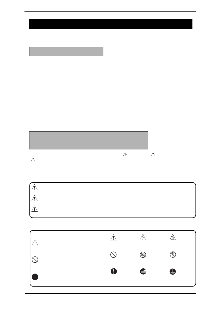
DESCRIPTION ITEMS FOR DANGER, WARNING AND CAUTION
In this Service Manual, each of three expressions " DANGER", " WARNING", and
" CAUTION" is defined as follows together with a symbol mark to be used in a limited
meaning.
When servicing the product, the relevant works (disassembling, reassembling, adjustment,
repair, maintenance, etc.) need to be conducted with utmost care.
DANGER: Action having a high possibility of suffering death or serious injury
WARNING: Action having a possibility of suffering death or serious injury
CAUTION: Action having a possibility of suffering a slight wound, medium
trouble and property damage
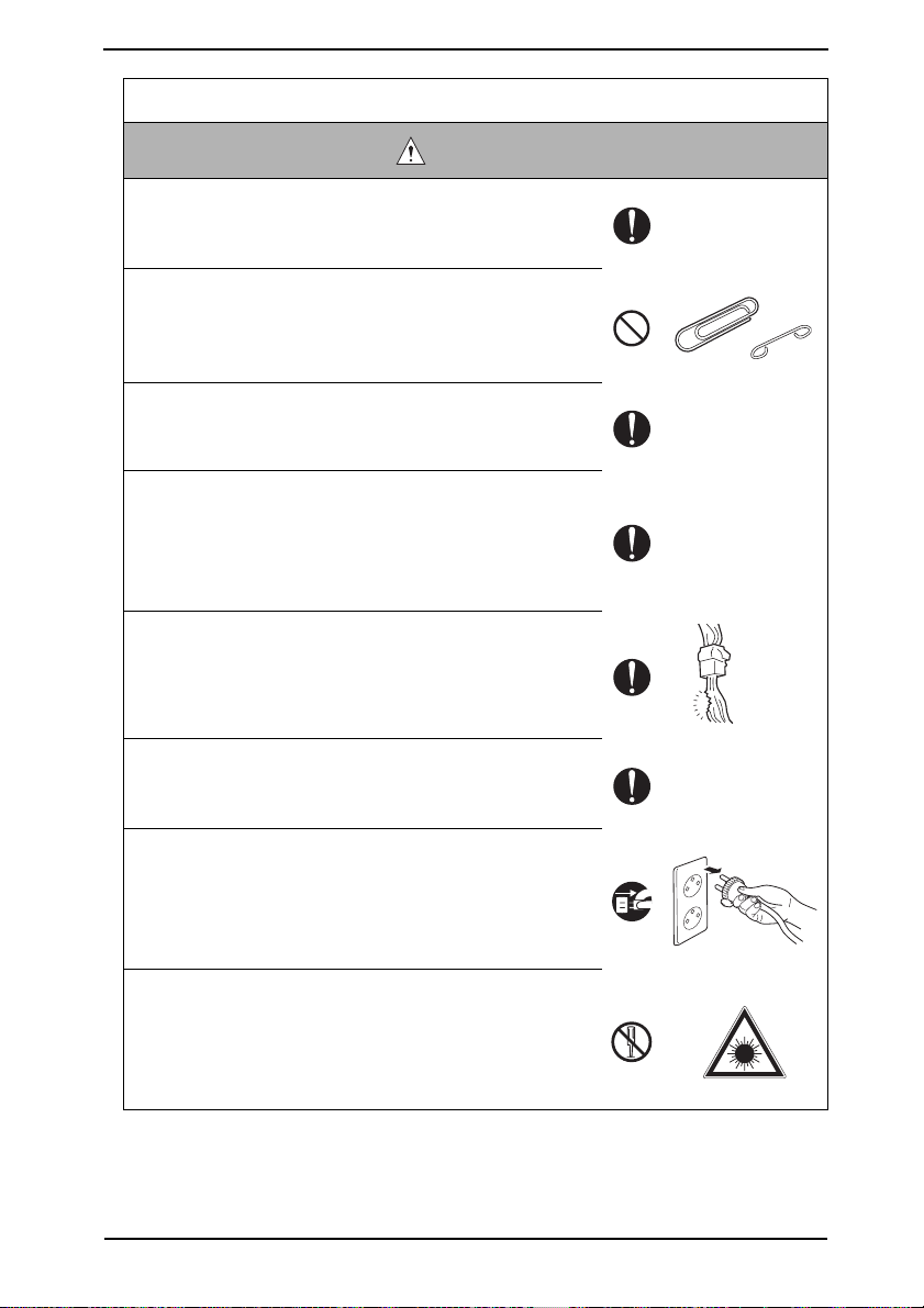
Symbols used for safety and important warning items are defined as follows:
:Precaution when using the
copier.
:Prohibition when using the
copier.
:Direction when using the
copier.
General
precaution
General
prohibition
General
instruction
Electric hazard High
Do not touch
with wet hand
Unplug Ground/Earth
temperature
Do not
disassemble
S-1
SAFETY AND IMPORTANT WARNING ITEMS
SAFETY WARNINGS
[1] MODIFICATIONS NOT AUTHORIZED BY KONICA MINOLTA
BUSINESS TECHNOLOGIES, INC.
Konica Minolta brand products are renowned for their high reliability. This reliability is
achieved through high-quality design and a solid service network.
Product design is a highly complicated and delicate process where numerous mechanical,
physical, and electrical aspects have to be taken into consideration, with the aim of arriving
at proper tolerances and safety factors. For this reason, unauthorized modifications involve
a high risk of degradation in performance and safety. Such modifications are therefore
strictly prohibited. The points listed below are not exhaustive, but they illustrate the reasoning behind this policy.
Prohibited Actions
DANGER
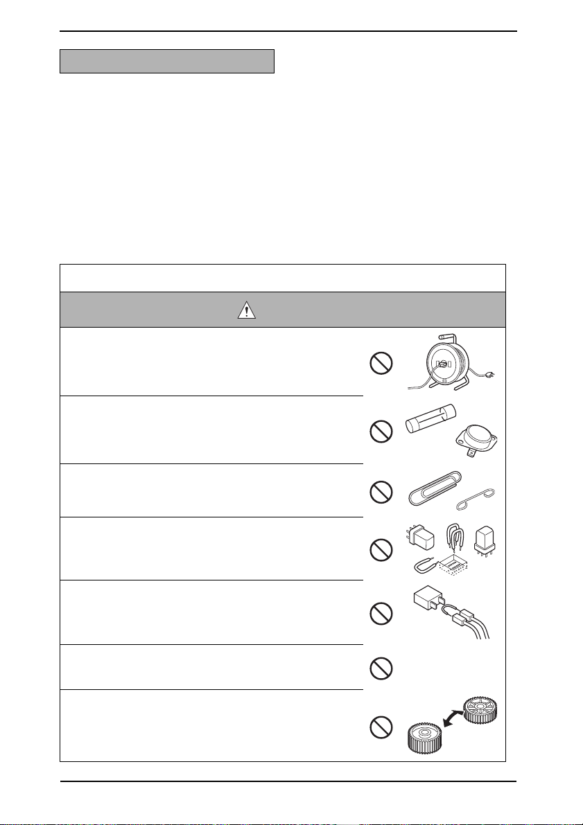
• Using any cables or power cord not specified by KMBT.
• Using any fuse or thermostat not specified by KMBT.
Safety will not be assured, leading to a risk of fire and
injury.
• Disabling fuse functions or bridging fuse terminals with
wire, metal clips, solder or similar object.
• Disabling relay functions (such as wedging paper between
relay contacts)
• Disabling safety functions (interlocks, safety circuits, etc.)
Safety will not be assured, leading to a risk of fire and
injury.
• Making any modification to the product unless instructed
by KMBT
• Using parts not specified by KMBT
S-2
SAFETY AND IMPORTANT WARNING ITEMS
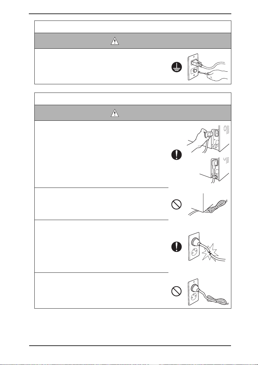
[2] POWER PLUG SELECTION
In some countries or areas, the power plug provided with the product may not fit wall outlet
used in the area. In that case, it is obligation of customer engineer (hereafter called the CE)
to attach appropriate power plug or power cord set in order to connect the product to the
supply.
Power Cord Set or Power Plug
WARNING
• Use power supply cord set which meets the following
criteria:
- provided with a plug having configuration intended for
the connection to wall outlet appropriate for the product's rated voltage and current, and
- the plug has pin/terminal(s) for grounding, and
- provided with three-conductor cable having enough current capacity, and
- the cord set meets regulatory requirements for the area.
Use of inadequate cord set leads to fire or electric shock.
• Attach power plug which meets the following criteria:
- having configuration intended for the connection to wall
outlet appropriate for the product's rated voltage and
current, and
- the plug has pin/terminal(s) for grounding, and
- meets regulatory requirements for the area.
Use of inadequate cord set leads to the product connecting to inadequate power supply (voltage, current capacity, grounding), and may result in fire or electric shock.
• Conductors in the power cable must be connected to ter-
minals of the plug according to the following order:
• Black or Brown: L (line)
• White or Light Blue: N (neutral)
• Green/Yellow: PE (earth)
Wrong connection may cancel safeguards within the
product, and results in fire or electric shock.
AC230V
AC208V 240V
S-3
SAFETY AND IMPORTANT WARNING ITEMS
[3] CHECKPOINTS WHEN PERFORMING ON-SITE SERVICE
Konica Minolta brand products are extensively tested before shipping, to ensure that all
applicable safety standards are met, in order to protect the customer and CE from the risk
of injury. However, in daily use, any electrical equipment may be subject to parts wear and
eventual failure. In order to maintain safety and reliability, the CE must perform regular
safety checks.
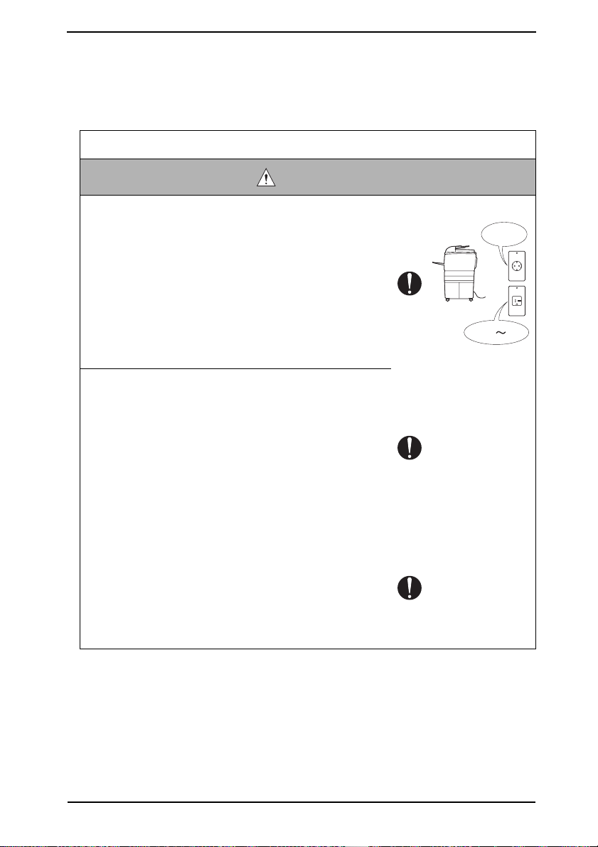
1. Power Supply
Connection to Power Supply
WARNING
• Check that mains voltage is as specified.
Connection to wrong voltage supply may result in fire or
electric shock.
• Connect power plug directly into wall outlet having same
configuration as the plug.
Use of an adapter leads to the product connecting to
inadequate power supply (voltage, current capacity,
grounding), and may result in fire or electric shock.
If proper wall outlet is not available, advice the customer
to contact qualified electrician for the installation.
• Plug the power cord into the dedicated wall outlet with a
capacity greater than the maximum power consumption.
If excessive current flows in the wall outlet, fire may
result.
• If two or more power cords can be plugged into the wall
outlet, the total load must not exceed the rating of the wall
outlet.
If excessive current flows in the wall outlet, fire may
result.
• Make sure the power cord is plugged in the wall outlet
securely.
Contact problems may lead to increased resistance,
overheating, and the risk of fire.
? V
kw
S-4
SAFETY AND IMPORTANT WARNING ITEMS
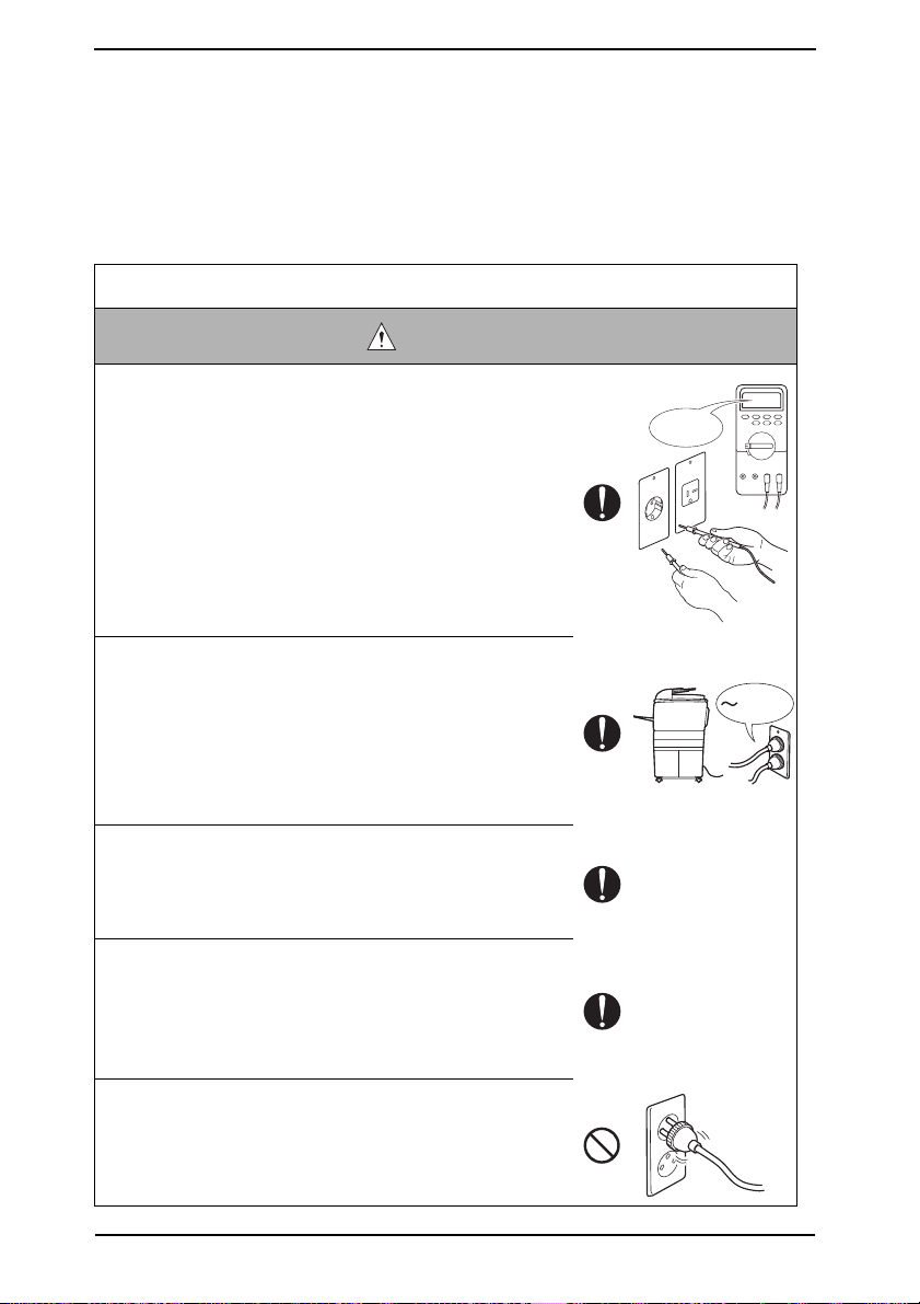
Connection to Power Supply
WARNING
• Check whether the product is grounded properly.
If current leakage occurs in an ungrounded product, you
may suffer electric shock while operating the product.
Connect power plug to grounded wall outlet.
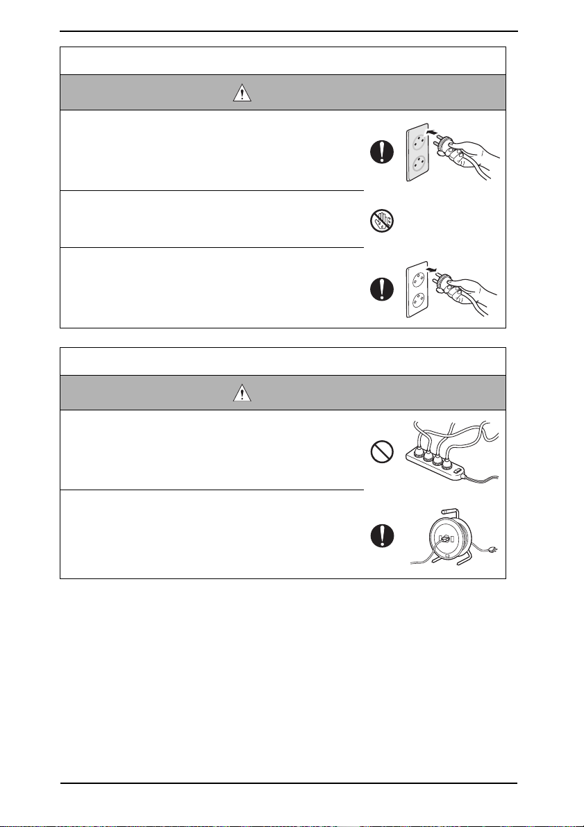
Power Plug and Cord
WARNING
• When using the power cord set (inlet type) that came with
this product, make sure the connector is securely inserted
in the inlet of the product.
When securing measure is provided, secure the cord with
the fixture properly.
If the power cord (inlet type) is not connected to the product securely, a contact problem may lead to increased
resistance, overheating, and risk of fire.
• Check whether the power cord is not stepped on or
pinched by a table and so on.
Overheating may occur there, leading to a risk of fire.
• Check whether the power cord is damaged. Check
whether the sheath is damaged.
If the power plug, cord, or sheath is damaged, replace
with a new power cord or cord set (with plug and connector on each end) specified by KMBT.
Using the damaged power cord may result in fire or electric shock.
• Do not bundle or tie the power cord.
Overheating may occur there, leading to a risk of fire.
S-5
SAFETY AND IMPORTANT WARNING ITEMS
Power Plug and Cord
WARNING
• Check whether dust is collected around the power plug
and wall outlet.
Using the power plug and wall outlet without removing
dust may result in fire.
• Do not insert the power plug into the wall outlet with a wet
hand.
The risk of electric shock exists.
• When unplugging the power cord, grasp the plug, not the
cable.
The cable may be broken, leading to a risk of fire and
electric shock.
Wiring
WARNING
• Never use multi-plug adapters to plug multiple power
cords in the same outlet.
If used, the risk of fire exists.
• When an extension cord is required, use a specified one.
Current that can flow in the extension cord is limited, so
using a too long extension cord may result in fire.
Do not use an extension cable reel with the cable taken
up. Fire may result.
S-6
SAFETY AND IMPORTANT WARNING ITEMS
2. Installation Requirements
Prohibited Installation Places
WARNING
• Do not place the product near flammable materials or vol-
atile materials that may catch fire.
A risk of fire exists.
• Do not place the product in a place exposed to water such
as rain.
A risk of fire and electric shock exists.
When not Using the Product for a long time
WARNING
• When the product is not used over an extended period of
time (holidays, etc.), switch it off and unplug the power
cord.
Dust collected around the power plug and outlet may
cause fire.
Ventilation
CAUTION
• The product generates ozone gas during operation, but it
will not be harmful to the human body.
If a bad smell of ozone is present in the following cases,
ventilate the room.
a. When the product is used in a poorly ventilated room
b. When taking a lot of copies
c. When using multiple products at the same time
Fixing
CAUTION
• Be sure to lock the caster stoppers.
In the case of an earthquake and so on, the product may
slide, leading to a injury.
S-7
SAFETY AND IMPORTANT WARNING ITEMS
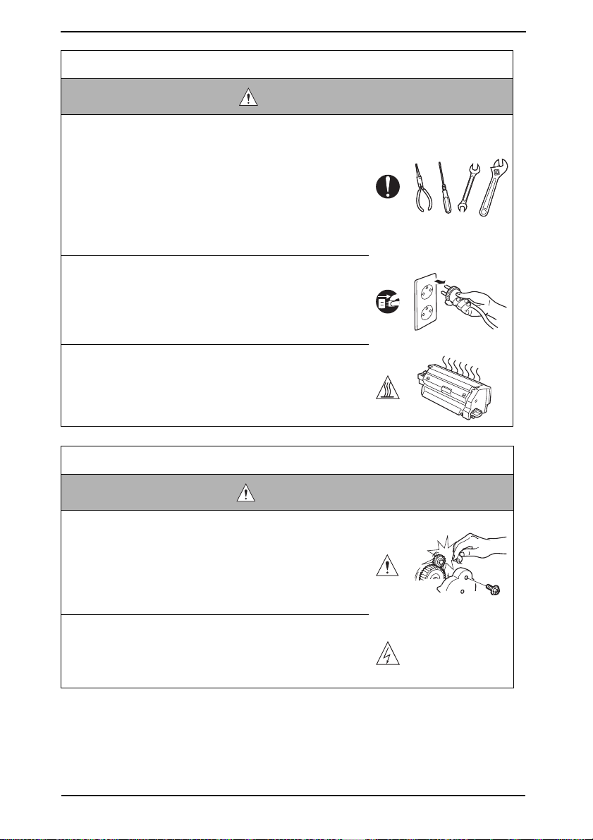
Inspection before Servicing
CAUTION
• Before conducting an inspection, read all relevant docu-
mentation (service manual, technical notices, etc.) and
proceed with the inspection following the prescribed pro-
cedure in safety clothes, using only the prescribed tools.
Do not make any adjustment not described in the docu-
mentation.
If the prescribed procedure or tool is not used, the product may break and a risk of injury or fire exists.
• Before conducting an inspection, be sure to disconnect
the power plugs from the product and options.
When the power plug is inserted in the wall outlet, some
units are still powered even if the POWER switch is
turned OFF. A risk of electric shock exists.
• The area around the fixing unit is hot.
You may get burnt.
Work Performed with the Product Powered On
WARNING
• Take every care when making adjustments or performing
an operation check with the product powered.
If you make adjustments or perform an operation check
with the external cover detached, you may touch live or
high-voltage parts or you may be caught in moving gears
or the timing belt, leading to a risk of injury.
• Take every care when servicing with the external cover
detached.
High-voltage exists around the drum unit. A risk of electric shock exists.
S-8
SAFETY AND IMPORTANT WARNING ITEMS
Safety Checkpoints
WARNING
• Check the exterior and frame for edges, burrs, and other
damages.
The user or CE may be injured.
• Do not allow any metal parts such as clips, staples, and
screws to fall into the product.
They can short internal circuits and cause electric shock
or fire.
• Check wiring for squeezing and any other damage.
Current can leak, leading to a risk of electric shock or
fire.
• Carefully remove all toner remnants and dust from electri-
cal parts and electrode units such as a charging corona
unit.
Current can leak, leading to a risk of product trouble or
fire.
• Check high-voltage cables and sheaths for any damage.
Current can leak, leading to a risk of electric shock or
fire.
• Check electrode units such as a charging corona unit for
deterioration and sign of leakage.
Current can leak, leading to a risk of trouble or fire.
• Before disassembling or adjusting the write unit (P/H unit)
incorporating a laser, make sure that the power cord has
been disconnected.
The laser light can enter your eye, leading to a risk of
loss of eyesight.
• Do not remove the cover of the write unit. Do not supply
power with the write unit shifted from the specified mount-
ing position.
The laser light can enter your eye, leading to a risk of
loss of eyesight.
S-9
SAFETY AND IMPORTANT WARNING ITEMS
Safety Checkpoints
WARNING
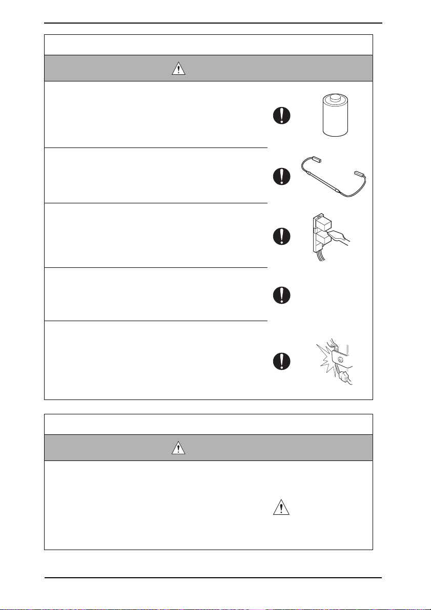
• When replacing a lithium battery, replace it with a new lith-
ium battery specified in the Parts Guide Manual. Dispose
of the used lithium battery using the method specified by
local authority.
Improper replacement can cause explosion.
• After replacing a part to which AC voltage is applied (e.g.,
optical lamp and fixing lamp), be sure to check the instal-
lation state.
A risk of fire exists.
• Check the interlock switch and actuator for loosening and
check whether the interlock functions properly.
If the interlock does not function, you may receive an
electric shock or be injured when you insert your hand in
the product (e.g., for clearing paper jam).
• Make sure the wiring cannot come into contact with sharp
edges, burrs, or other pointed parts.
Current can leak, leading to a risk of electric shock or
fire.
• Make sure that all screws, components, wiring, connec-
tors, etc. that were removed for safety check and mainte-
nance have been reinstalled in the original location. (Pay
special attention to forgotten connectors, pinched cables,
forgotten screws, etc.)
A risk of product trouble, electric shock, and fire exists.
Handling of Consumables
WARNING
• Toner and developer are not harmful substances, but care
must be taken not to breathe excessive amounts or let the
substances come into contact with eyes, etc. It may be
stimulative.
If the substances get in the eye, rinse with plenty of water
immediately. When symptoms are noticeable, consult a
physician.
S-10
SAFETY AND IMPORTANT WARNING ITEMS
Handling of Consumables
WARNING
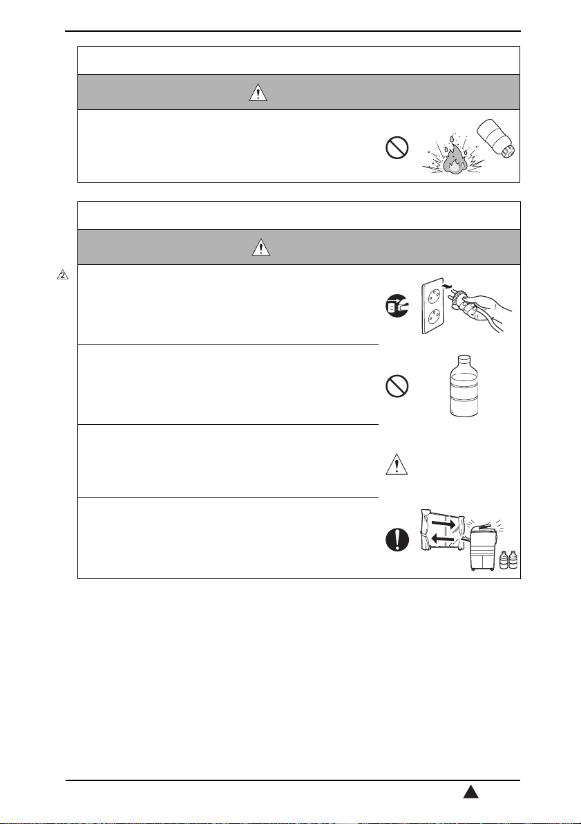
• Never throw the used cartridge and toner into fire.
You may be burned due to dust explosion.
Handling of Service Materials
CAUTION
• Unplug the power cord from the wall outlet.
Isopropyl alcohol and acetone are highly flammable and
must be handled with care. A risk of fire exists.
• Do not replace the cover or turn the product ON before
any solvent remnants on the cleaned parts have fully
evaporated.
A risk of fire exists.
• Use only a small amount of cleaner at a time and take
care not to spill any liquid. If this happens, immediately
wipe it off.
A risk of fire exists.
• When using any solvent, ventilate the room well.
Breathing large quantities of organic solvents can lead to
discomfort.
S-11
2

SAFETY INFORMATION
SAFETY INFORMATION
IMPORTANT NOTICE
The Center for Devices and Radiological Health (CDRH) of the U.S. Food and Drug Administration implemented regulations for laser products manufactured since August 1, 1976.
Compliance is mandatory for products marketed in the United States.
This copier is certified as a "Class 1" laser product under the U.S.
Department of Health and Human Services (DHHS) Radiation Performance Standard
according to the Radiation Control for Health and Safety Act of 1968. Since radiation emitted inside this copier is completely confined within protective housings and external covers,
the laser beam cannot escape during any phase of normal user operation.
S-12
SAFETY INFORMATION
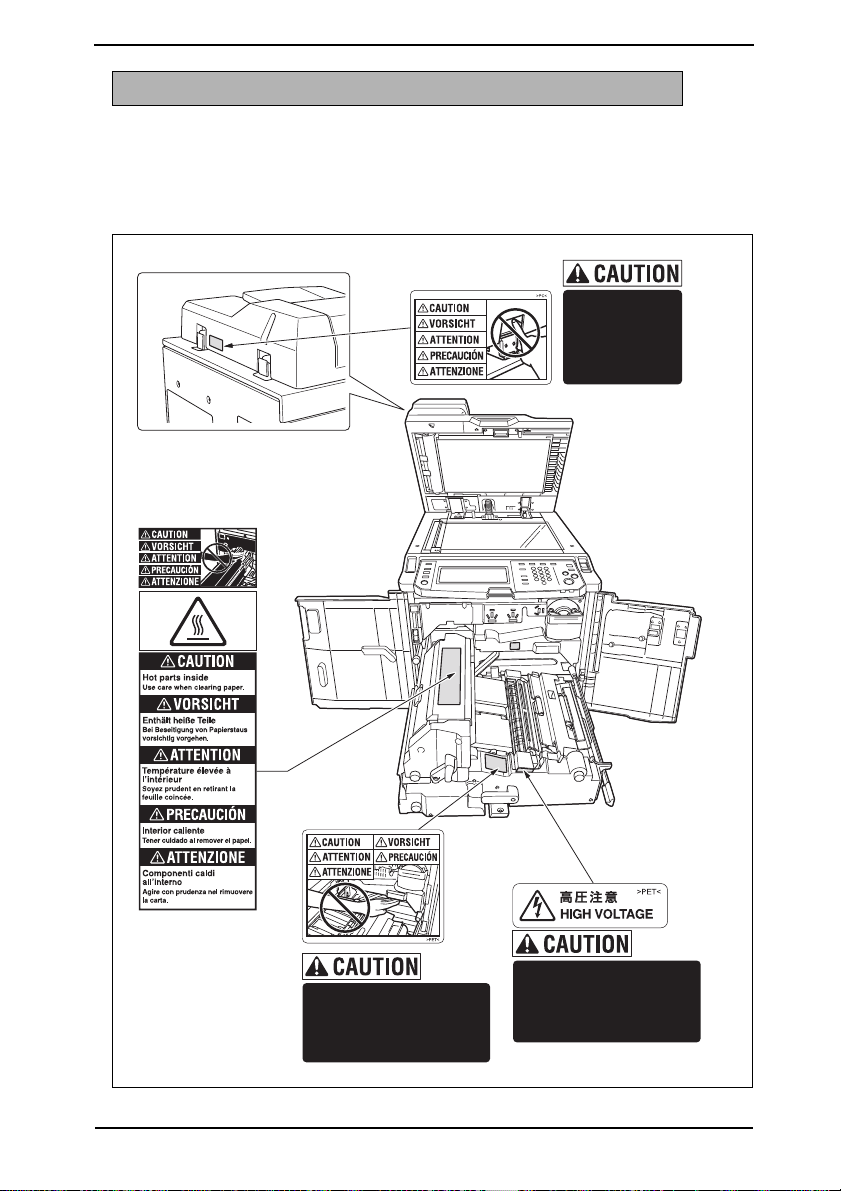
INDICATION OF WARNING ON THE MACHINE
Caution labels shown below are attached in some areas on/in the machine.
When accessing these areas for maintenance, repair, or adjustment, special care should
be taken to avoid burns and electric shock.
For metric area:
DO NOT INSERT
your finger into
the two EDH
hinge portions;
otherwise you
may be injured.
DO NOT put your hand
between the main body and
developing fixing unit;
otherwise you may be
injured.
High voltage is present
around this part.
Do not touch this part
in order to reduce the risk
of electric shock.
57aap0e001na
S-13
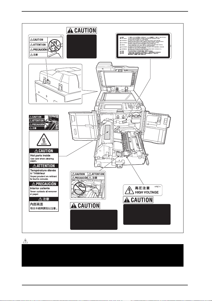
SAFETY INFORMATION
For inch area:
DO NOT INSERT
your finger into
the two EDH
hinge portions;
otherwise you
may be injured.
High voltage is present
DO NOT put your hand
between the main body and
developing fixing unit;
otherwise you may be
injured.
around this part.
Do not touch this part
in order to reduce the risk
of electric shock.
57aap0e002na
CAUTION:
• You may be burned or injured if you touch any area that you are advised by any
caution label to keep yourself away from. Do not remove caution labels. And also,
when the caution label is peeled off or soiled and cannot be seen clearly, replace
it with a new caution label.
S-14

MEASURES TO TAKE IN CASE OF AN ACCIDENT
MEASURES TO TAKE IN CASE OF
AN ACCIDENT
1. If an accident has occurred, the distributor who has been notified first must immediately
take emergency measures to provide relief to affected persons and to prevent further
damage.
2. If a report of a serious accident has been received from a customer, an on-site evaluation must be carried out quickly and KMBT must be notified.
3. To determine the cause of the accident, conditions and materials must be recorded
through direct on-site checks, in accordance with instructions issued by KMBT.
4. For reports and measures concerning serious accidents, follow the regulations specified by every distributor.
S-15

MEASURES TO TAKE IN CASE OF AN ACCIDENT
Blank page
S-16

Composition of the service manual
This service manual consists of the following sections and chapters:
<Theory of Operation section>
OUTLINE: System configuration, product specifications,
unit configuration, and paper path
COMPOSITION/OPERATION: Configuration of each unit, explanation of the operating
system, and explanation of the control system
This section gives, as information for the CE to get a full understanding of the product, a
rough outline of the object and role of each function, the relationship between the electrical
system and the mechanical system, and the timing of operation of each part.
<Field service section>
OUTLINE: System configuration, and product specifications
MAINTENANCE: Service schedule *, maintenance steps,
list of service tools and directions for use *,
firmware version up method *,
and removal/reinstallation methods of major parts
ADJUSTMENT/SETTING: Utility mode *, service mode *, security and mechanical
adjustment
TROUBLESHOOTING*: List of jam codes, their causes, operation when a jam
occurs and its release method, and list of error codes,
their causes, operation when a warning is issued and esti-
mated abnormal parts.
APPENDIX*: Parts layout drawings, connector layout drawings, timing
chart, overall layout drawing
This section gives, as information required by the CE at the site (or at the customer's
premise), a rough outline of the service schedule and its details, maintenance steps, the
object and role of each adjustment, error codes and supplementary information.
The details of items with an asterisk "*" are described only in the service manual of
the main body.
C-1
Notation of the service manual
A. Product name
In this manual, each of the products is described as follows:
(1) IC board: Standard printer
(2) bizhub 750/600: Main body
(3) PS-502 PostScript3 Option: PS3 Option
(4) Microsoft Windows 95: Windows 95
Microsoft Windows 98: Windows 98
Microsoft Windows Me: Windows Me
Microsoft Windows NT 4.0: Windows NT 4.0 or Windows NT
Microsoft Windows 2000: Windows 2000
Microsoft Windows XP: Windows XP
When the description is made in combination of the OS's mentioned above:
Windows 95/98/Me
Windows NT 4.0/2000
Windows NT/2000/XP
Windows 95/98/Me/NT/2000/XP
B. Brand name
The company names and product names mentioned in this manual are the brand name or
the registered trademark of each company.
C. Electrical parts and signals
Those listed by way of example below are not exhaustive, but only some instances among
many.
Classification Load symbol Ex. of signal name Description
IN
PS
Sensor PS
Solenoid SD
Clutch CL
Door PS1
SIG
102 PS
24V Power to drive the solenoid
DRV
SOL
24V Power to drive the clutch
DRV
SOL
Sensor detection signal
Drive signal
Drive signal
C-2

Classification Load symbol Ex. of signal name Description
24V Power to drive the motor
CONT Drive signal
Motor M
Motor M
Fan FM
Others TH1.S, ANG Analog signal
DRV1
DRV2
D1
D2
_U
_V
_W
DRV1
DRV2
DRV3
D1
D2
D3
D4
DRV A
DRV A
DRV B
DRV B
A
/A
B
/B
AB
BB
CLK, PLL PLL control signal
LCK, Lock, LD PLL lock signal
FR Forward/reverse rotation signal
EM, Lock, LCK, LD Motor lock abnormality
BLK Drive brake signal
P/S Power/stop
S/S
SS
CW/CCW, F/R Rotational direction switching signal
ENB Effective signal
TEMP_ER Motor temperature abnormality detection signal
24V Power to drive the fan motor
CONT, DRIVE Drive signal
HL Speed control signal (2 speeds)
EM, Lock, LCK, FEM Detection signal
Drive signals of two kinds
Drive signals (control signals) of three kinds
Drive signals (control signals) of four kinds
Motor, phases A and B control signals
Operating load start/stop signal
C-3
Classification Load symbol Ex. of signal name Description
Ground
Serial com-
munication
SG, S.GND, S_GND Signal ground
PG, P.GND Power ground
DCD Data carrier detection
SIN Serial input
SOUT Serial output
DTR Data terminal operation available
GND Signal ground (earth)
DSR, DSET Data set ready
RTS Transmission request signal
CTS Consent transmission signal
RI Ring indicator
TXD Serial transmission data
RXD Serial reception data
C-4

SERVICE MANUAL
750/600
Main body
Theory of Operation
2006.05
Ver. 2.0
Revision history
After publication of this service manual, the parts and mechanism may be subject to change for
improvement of their performance.
Therefore, the descriptions given in this service manual may not coincide with the actual machine.
When any change has been made to the descriptions in the service manual, a revised version will be
issued with a revision mark added as required.
Revision mark:
• To indicate clearly a section revised, show to the left of the revised section.
A number within represents the number of times the revision has been made.
1
1
• To indicate clearly a section revised, show in the lower outside section of the correspond-
1
ing page.
A number within represents the number of times the revision has been made.
1
NOTE
Revision marks shown in a page are restricted only to the latest ones with the old ones deleted.
• When a page revised in Ver. 2.0 has been changed in Ver. 3.0:
The revision marks for Ver. 3.0 only are shown with those for Ver. 2.0 deleted.
• When a page revised in Ver. 2.0 has not been changed in Ver. 3.0:
The revision marks for Ver. 2.0 are left as they are.
2006/05 2.0
2005/08 1.0 — Issue of the first edition
Date Service manual Ver. Revision mark Descriptions of revision
Addition of FS-505 and correction of an error in
writing

Theory of Operation Ver2.0 May.2006
bizhub 750/600
CONTENTS
CONTENTS
OUTLINE
1. SYSTEM CONFIGURATION . . . . . . . . . . . . . . . . . . . . . . . . . . . . . . . . . . . . . . . . . . . . . . . . . . . . . . . . . . . . 1
2. PRODUCT SPECIFICATIONS. . . . . . . . . . . . . . . . . . . . . . . . . . . . . . . . . . . . . . . . . . . . . . . . . . . . . . . . . . . 3
3. UNIT CONFIGURATION . . . . . . . . . . . . . . . . . . . . . . . . . . . . . . . . . . . . . . . . . . . . . . . . . . . . . . . . . . . . . . . 6
4. PAPER PATH. . . . . . . . . . . . . . . . . . . . . . . . . . . . . . . . . . . . . . . . . . . . . . . . . . . . . . . . . . . . . . . . . . . . . . . 7
COMPOSITION/OPERATION
5. OVERALL CONFIGURATION . . . . . . . . . . . . . . . . . . . . . . . . . . . . . . . . . . . . . . . . . . . . . . . . . . . . . . . . . . . 9
5.1 Time chart when the power is turned ON . . . . . . . . . . . . . . . . . . . . . . . . . . . . . . . . . . . . . . . . . . . . . . 9
5.2 Control block diagram . . . . . . . . . . . . . . . . . . . . . . . . . . . . . . . . . . . . . . . . . . . . . . . . . . . . . . . . . . . . 11
6. SCANNER SECTION . . . . . . . . . . . . . . . . . . . . . . . . . . . . . . . . . . . . . . . . . . . . . . . . . . . . . . . . . . . . . . . . 12
6.1 Composition . . . . . . . . . . . . . . . . . . . . . . . . . . . . . . . . . . . . . . . . . . . . . . . . . . . . . . . . . . . . . . . . . . . 12
6.2 Drive . . . . . . . . . . . . . . . . . . . . . . . . . . . . . . . . . . . . . . . . . . . . . . . . . . . . . . . . . . . . . . . . . . . . . . . . . 12
6.3 Operation . . . . . . . . . . . . . . . . . . . . . . . . . . . . . . . . . . . . . . . . . . . . . . . . . . . . . . . . . . . . . . . . . . . . . 13
6.3.1 Scan/exposure lamp control . . . . . . . . . . . . . . . . . . . . . . . . . . . . . . . . . . . . . . . . . . . . . . . . . . 13
6.3.2 Original size detection control. . . . . . . . . . . . . . . . . . . . . . . . . . . . . . . . . . . . . . . . . . . . . . . . . . 18
6.3.3 AE control . . . . . . . . . . . . . . . . . . . . . . . . . . . . . . . . . . . . . . . . . . . . . . . . . . . . . . . . . . . . . . . . 19
6.3.4 Image processing. . . . . . . . . . . . . . . . . . . . . . . . . . . . . . . . . . . . . . . . . . . . . . . . . . . . . . . . . . . 19
7. WRITE SECTION . . . . . . . . . . . . . . . . . . . . . . . . . . . . . . . . . . . . . . . . . . . . . . . . . . . . . . . . . . . . . . . . . . . 20
7.1 Composition . . . . . . . . . . . . . . . . . . . . . . . . . . . . . . . . . . . . . . . . . . . . . . . . . . . . . . . . . . . . . . . . . . . 20
7.2 Operation . . . . . . . . . . . . . . . . . . . . . . . . . . . . . . . . . . . . . . . . . . . . . . . . . . . . . . . . . . . . . . . . . . . . . 20
7.2.1 Laser beam path . . . . . . . . . . . . . . . . . . . . . . . . . . . . . . . . . . . . . . . . . . . . . . . . . . . . . . . . . . . 20
7.2.2 Write control . . . . . . . . . . . . . . . . . . . . . . . . . . . . . . . . . . . . . . . . . . . . . . . . . . . . . . . . . . . . . . 21
7.2.3 Polygon control . . . . . . . . . . . . . . . . . . . . . . . . . . . . . . . . . . . . . . . . . . . . . . . . . . . . . . . . . . . . 21
7.2.4 Image stabilization control . . . . . . . . . . . . . . . . . . . . . . . . . . . . . . . . . . . . . . . . . . . . . . . . . . . . 21
8. PHOTO CONDUCTOR SECTION . . . . . . . . . . . . . . . . . . . . . . . . . . . . . . . . . . . . . . . . . . . . . . . . . . . . . . . 22
8.1 Composition . . . . . . . . . . . . . . . . . . . . . . . . . . . . . . . . . . . . . . . . . . . . . . . . . . . . . . . . . . . . . . . . . . . 22
8.2 Drive . . . . . . . . . . . . . . . . . . . . . . . . . . . . . . . . . . . . . . . . . . . . . . . . . . . . . . . . . . . . . . . . . . . . . . . . . 23
8.2.1 Drum drive . . . . . . . . . . . . . . . . . . . . . . . . . . . . . . . . . . . . . . . . . . . . . . . . . . . . . . . . . . . . . . . . 23
8.2.2 Drum claw drive . . . . . . . . . . . . . . . . . . . . . . . . . . . . . . . . . . . . . . . . . . . . . . . . . . . . . . . . . . . . 23
8.3 Operation . . . . . . . . . . . . . . . . . . . . . . . . . . . . . . . . . . . . . . . . . . . . . . . . . . . . . . . . . . . . . . . . . . . . . 24
8.3.1 Image creation control . . . . . . . . . . . . . . . . . . . . . . . . . . . . . . . . . . . . . . . . . . . . . . . . . . . . . . . 24
8.3.2 Drum claw control . . . . . . . . . . . . . . . . . . . . . . . . . . . . . . . . . . . . . . . . . . . . . . . . . . . . . . . . . . 25
8.3.3 Cooling around the drum . . . . . . . . . . . . . . . . . . . . . . . . . . . . . . . . . . . . . . . . . . . . . . . . . . . . . 25
8.3.4 Image stabilization control . . . . . . . . . . . . . . . . . . . . . . . . . . . . . . . . . . . . . . . . . . . . . . . . . . . . 26
9. CHARGING SECTION . . . . . . . . . . . . . . . . . . . . . . . . . . . . . . . . . . . . . . . . . . . . . . . . . . . . . . . . . . . . . . . 27
9.1 Composition . . . . . . . . . . . . . . . . . . . . . . . . . . . . . . . . . . . . . . . . . . . . . . . . . . . . . . . . . . . . . . . . . . . 27
9.2 Drive . . . . . . . . . . . . . . . . . . . . . . . . . . . . . . . . . . . . . . . . . . . . . . . . . . . . . . . . . . . . . . . . . . . . . . . . . 27
9.3 Operation . . . . . . . . . . . . . . . . . . . . . . . . . . . . . . . . . . . . . . . . . . . . . . . . . . . . . . . . . . . . . . . . . . . . . 28
9.3.1 Charging control . . . . . . . . . . . . . . . . . . . . . . . . . . . . . . . . . . . . . . . . . . . . . . . . . . . . . . . . . . . 28
9.3.2 Wire cleaning control . . . . . . . . . . . . . . . . . . . . . . . . . . . . . . . . . . . . . . . . . . . . . . . . . . . . . . . . 28
9.3.3 Erase lamp control . . . . . . . . . . . . . . . . . . . . . . . . . . . . . . . . . . . . . . . . . . . . . . . . . . . . . . . . . . 28
10. TRANSFER/SEPARATION SECTION . . . . . . . . . . . . . . . . . . . . . . . . . . . . . . . . . . . . . . . . . . . . . . . . . . . . 29
10.1 Composition . . . . . . . . . . . . . . . . . . . . . . . . . . . . . . . . . . . . . . . . . . . . . . . . . . . . . . . . . . . . . . . . . . . 29
bizhub 750/600
i

CONTENTS
10.2 Drive . . . . . . . . . . . . . . . . . . . . . . . . . . . . . . . . . . . . . . . . . . . . . . . . . . . . . . . . . . . . . . . . . . . . . . . . . 29
10.3 Operation . . . . . . . . . . . . . . . . . . . . . . . . . . . . . . . . . . . . . . . . . . . . . . . . . . . . . . . . . . . . . . . . . . . . . 30
10.3.1 Transfer guide control . . . . . . . . . . . . . . . . . . . . . . . . . . . . . . . . . . . . . . . . . . . . . . . . . . . . . . . . 30
10.3.2 Transfer/separation control . . . . . . . . . . . . . . . . . . . . . . . . . . . . . . . . . . . . . . . . . . . . . . . . . . . . 30
10.3.3 Transfer exposure lamp control . . . . . . . . . . . . . . . . . . . . . . . . . . . . . . . . . . . . . . . . . . . . . . . . 30
bizhub 750/600
10.3.4 Wire cleaning control . . . . . . . . . . . . . . . . . . . . . . . . . . . . . . . . . . . . . . . . . . . . . . . . . . . . . . . . 31
11.DEVELOPING UNIT . . . . . . . . . . . . . . . . . . . . . . . . . . . . . . . . . . . . . . . . . . . . . . . . . . . . . . . . . . . . . . . . . 32
11.1 Composition . . . . . . . . . . . . . . . . . . . . . . . . . . . . . . . . . . . . . . . . . . . . . . . . . . . . . . . . . . . . . . . . . . . 32
11.2 Drive . . . . . . . . . . . . . . . . . . . . . . . . . . . . . . . . . . . . . . . . . . . . . . . . . . . . . . . . . . . . . . . . . . . . . . . . . 32
11.3 Operation . . . . . . . . . . . . . . . . . . . . . . . . . . . . . . . . . . . . . . . . . . . . . . . . . . . . . . . . . . . . . . . . . . . . . 33
11.3.1 Conveyance of developer . . . . . . . . . . . . . . . . . . . . . . . . . . . . . . . . . . . . . . . . . . . . . . . . . . . . . 33
11.3.2 Developing bias . . . . . . . . . . . . . . . . . . . . . . . . . . . . . . . . . . . . . . . . . . . . . . . . . . . . . . . . . . . . 33
11.3.3 Developing suction control . . . . . . . . . . . . . . . . . . . . . . . . . . . . . . . . . . . . . . . . . . . . . . . . . . . . 34
11.3.4 Image stabilization control . . . . . . . . . . . . . . . . . . . . . . . . . . . . . . . . . . . . . . . . . . . . . . . . . . . . 34
12. TONER SUPPLY SECTION. . . . . . . . . . . . . . . . . . . . . . . . . . . . . . . . . . . . . . . . . . . . . . . . . . . . . . . . . . . . 35
12.1 Composition . . . . . . . . . . . . . . . . . . . . . . . . . . . . . . . . . . . . . . . . . . . . . . . . . . . . . . . . . . . . . . . . . . . 35
12.2 Drive . . . . . . . . . . . . . . . . . . . . . . . . . . . . . . . . . . . . . . . . . . . . . . . . . . . . . . . . . . . . . . . . . . . . . . . . . 35
12.3 Operation . . . . . . . . . . . . . . . . . . . . . . . . . . . . . . . . . . . . . . . . . . . . . . . . . . . . . . . . . . . . . . . . . . . . . 36
12.3.1 Toner remaining detection control . . . . . . . . . . . . . . . . . . . . . . . . . . . . . . . . . . . . . . . . . . . . . . 36
12.3.2 Toner supply control . . . . . . . . . . . . . . . . . . . . . . . . . . . . . . . . . . . . . . . . . . . . . . . . . . . . . . . . . 36
12.3.3 Toner conveyance control . . . . . . . . . . . . . . . . . . . . . . . . . . . . . . . . . . . . . . . . . . . . . . . . . . . . 37
13. CLEANING/TONER RECYCLE SECTION . . . . . . . . . . . . . . . . . . . . . . . . . . . . . . . . . . . . . . . . . . . . . . . . . 38
13.1 Composition . . . . . . . . . . . . . . . . . . . . . . . . . . . . . . . . . . . . . . . . . . . . . . . . . . . . . . . . . . . . . . . . . . . 38
13.2 Drive . . . . . . . . . . . . . . . . . . . . . . . . . . . . . . . . . . . . . . . . . . . . . . . . . . . . . . . . . . . . . . . . . . . . . . . . . 38
13.3 Operation . . . . . . . . . . . . . . . . . . . . . . . . . . . . . . . . . . . . . . . . . . . . . . . . . . . . . . . . . . . . . . . . . . . . . 39
13.3.1 Toner guide roller control . . . . . . . . . . . . . . . . . . . . . . . . . . . . . . . . . . . . . . . . . . . . . . . . . . . . . 39
13.3.2 Other controls . . . . . . . . . . . . . . . . . . . . . . . . . . . . . . . . . . . . . . . . . . . . . . . . . . . . . . . . . . . . . 39
13.3.3 Image stabilization control . . . . . . . . . . . . . . . . . . . . . . . . . . . . . . . . . . . . . . . . . . . . . . . . . . . . 39
14. PAPER FEED SECTION (trays 1 and 2) . . . . . . . . . . . . . . . . . . . . . . . . . . . . . . . . . . . . . . . . . . . . . . . . . . . 40
14.1 Composition . . . . . . . . . . . . . . . . . . . . . . . . . . . . . . . . . . . . . . . . . . . . . . . . . . . . . . . . . . . . . . . . . . . 40
14.2 Drive . . . . . . . . . . . . . . . . . . . . . . . . . . . . . . . . . . . . . . . . . . . . . . . . . . . . . . . . . . . . . . . . . . . . . . . . . 41
14.2.1 Paper feed drive . . . . . . . . . . . . . . . . . . . . . . . . . . . . . . . . . . . . . . . . . . . . . . . . . . . . . . . . . . . . 41
14.2.2 Tray lift drive . . . . . . . . . . . . . . . . . . . . . . . . . . . . . . . . . . . . . . . . . . . . . . . . . . . . . . . . . . . . . . . 42
14.3 Operation . . . . . . . . . . . . . . . . . . . . . . . . . . . . . . . . . . . . . . . . . . . . . . . . . . . . . . . . . . . . . . . . . . . . . 43
14.3.1 Up/down control . . . . . . . . . . . . . . . . . . . . . . . . . . . . . . . . . . . . . . . . . . . . . . . . . . . . . . . . . . . 43
14.3.2 Paper feed control . . . . . . . . . . . . . . . . . . . . . . . . . . . . . . . . . . . . . . . . . . . . . . . . . . . . . . . . . . 44
14.3.3 Paper empty detection control . . . . . . . . . . . . . . . . . . . . . . . . . . . . . . . . . . . . . . . . . . . . . . . . . 47
14.3.4 Remaining paper detection control . . . . . . . . . . . . . . . . . . . . . . . . . . . . . . . . . . . . . . . . . . . . . . 47
14.3.5 Horizontal conveyance control (tray 1) . . . . . . . . . . . . . . . . . . . . . . . . . . . . . . . . . . . . . . . . . . . 47
15. PAPER FEED SECTION (trays 3 and 4) . . . . . . . . . . . . . . . . . . . . . . . . . . . . . . . . . . . . . . . . . . . . . . . . . . . 49
15.1 Composition . . . . . . . . . . . . . . . . . . . . . . . . . . . . . . . . . . . . . . . . . . . . . . . . . . . . . . . . . . . . . . . . . . . 49
15.2 Drive . . . . . . . . . . . . . . . . . . . . . . . . . . . . . . . . . . . . . . . . . . . . . . . . . . . . . . . . . . . . . . . . . . . . . . . . . 50
15.2.1 Paper feed drive . . . . . . . . . . . . . . . . . . . . . . . . . . . . . . . . . . . . . . . . . . . . . . . . . . . . . . . . . . . . 50
15.2.2 Tray lift drive . . . . . . . . . . . . . . . . . . . . . . . . . . . . . . . . . . . . . . . . . . . . . . . . . . . . . . . . . . . . . . . 51
15.3 Operation . . . . . . . . . . . . . . . . . . . . . . . . . . . . . . . . . . . . . . . . . . . . . . . . . . . . . . . . . . . . . . . . . . . . . 52
15.3.1 Up/down control . . . . . . . . . . . . . . . . . . . . . . . . . . . . . . . . . . . . . . . . . . . . . . . . . . . . . . . . . . . 52
15.3.2 Paper feed control . . . . . . . . . . . . . . . . . . . . . . . . . . . . . . . . . . . . . . . . . . . . . . . . . . . . . . . . . . 52
15.3.3 Paper size detection control . . . . . . . . . . . . . . . . . . . . . . . . . . . . . . . . . . . . . . . . . . . . . . . . . . . 53
15.3.4 Paper empty detection control . . . . . . . . . . . . . . . . . . . . . . . . . . . . . . . . . . . . . . . . . . . . . . . . . 53
15.3.5 Remaining paper detection control . . . . . . . . . . . . . . . . . . . . . . . . . . . . . . . . . . . . . . . . . . . . . . 53
Theory of Operation Ver2.0 May.2006
ii

Theory of Operation Ver2.0 May.2006
15.3.6 Dehumidification heater control . . . . . . . . . . . . . . . . . . . . . . . . . . . . . . . . . . . . . . . . . . . . . . . . 53
16. BYPASS TRAY. . . . . . . . . . . . . . . . . . . . . . . . . . . . . . . . . . . . . . . . . . . . . . . . . . . . . . . . . . . . . . . . . . . . . 54
16.1 Composition . . . . . . . . . . . . . . . . . . . . . . . . . . . . . . . . . . . . . . . . . . . . . . . . . . . . . . . . . . . . . . . . . . . 54
16.2 Drive . . . . . . . . . . . . . . . . . . . . . . . . . . . . . . . . . . . . . . . . . . . . . . . . . . . . . . . . . . . . . . . . . . . . . . . . . 55
16.2.1 Paper feed drive. . . . . . . . . . . . . . . . . . . . . . . . . . . . . . . . . . . . . . . . . . . . . . . . . . . . . . . . . . . . 55
16.2.2 Tray lift drive. . . . . . . . . . . . . . . . . . . . . . . . . . . . . . . . . . . . . . . . . . . . . . . . . . . . . . . . . . . . . . . 55
16.3 Operation . . . . . . . . . . . . . . . . . . . . . . . . . . . . . . . . . . . . . . . . . . . . . . . . . . . . . . . . . . . . . . . . . . . . . 56
16.3.1 Up/down control . . . . . . . . . . . . . . . . . . . . . . . . . . . . . . . . . . . . . . . . . . . . . . . . . . . . . . . . . . . 56
16.3.2 Paper size detection control . . . . . . . . . . . . . . . . . . . . . . . . . . . . . . . . . . . . . . . . . . . . . . . . . . . 56
16.3.3 Paper feed control . . . . . . . . . . . . . . . . . . . . . . . . . . . . . . . . . . . . . . . . . . . . . . . . . . . . . . . . . . 57
16.3.4 Paper empty detection control . . . . . . . . . . . . . . . . . . . . . . . . . . . . . . . . . . . . . . . . . . . . . . . . . 58
16.3.5 Remaining paper detection control. . . . . . . . . . . . . . . . . . . . . . . . . . . . . . . . . . . . . . . . . . . . . . 58
17. VERTICAL CONVEYANCE SECTION . . . . . . . . . . . . . . . . . . . . . . . . . . . . . . . . . . . . . . . . . . . . . . . . . . . . 59
17.1 Composition . . . . . . . . . . . . . . . . . . . . . . . . . . . . . . . . . . . . . . . . . . . . . . . . . . . . . . . . . . . . . . . . . . . 59
17.2 Drive . . . . . . . . . . . . . . . . . . . . . . . . . . . . . . . . . . . . . . . . . . . . . . . . . . . . . . . . . . . . . . . . . . . . . . . . . 60
17.3 Operation . . . . . . . . . . . . . . . . . . . . . . . . . . . . . . . . . . . . . . . . . . . . . . . . . . . . . . . . . . . . . . . . . . . . . 61
17.3.1 Conveyance control . . . . . . . . . . . . . . . . . . . . . . . . . . . . . . . . . . . . . . . . . . . . . . . . . . . . . . . . . 61
18. REGISTRATION SECTION . . . . . . . . . . . . . . . . . . . . . . . . . . . . . . . . . . . . . . . . . . . . . . . . . . . . . . . . . . . . 64
18.1 Composition . . . . . . . . . . . . . . . . . . . . . . . . . . . . . . . . . . . . . . . . . . . . . . . . . . . . . . . . . . . . . . . . . . . 64
18.2 Drive . . . . . . . . . . . . . . . . . . . . . . . . . . . . . . . . . . . . . . . . . . . . . . . . . . . . . . . . . . . . . . . . . . . . . . . . . 65
18.2.1 Registration drive . . . . . . . . . . . . . . . . . . . . . . . . . . . . . . . . . . . . . . . . . . . . . . . . . . . . . . . . . . . 65
18.2.2 Loop roller drive . . . . . . . . . . . . . . . . . . . . . . . . . . . . . . . . . . . . . . . . . . . . . . . . . . . . . . . . . . . . 65
18.3 Operation . . . . . . . . . . . . . . . . . . . . . . . . . . . . . . . . . . . . . . . . . . . . . . . . . . . . . . . . . . . . . . . . . . . . . 66
18.3.1 Loop control . . . . . . . . . . . . . . . . . . . . . . . . . . . . . . . . . . . . . . . . . . . . . . . . . . . . . . . . . . . . . . 66
18.3.2 Paper mis-centering correction control. . . . . . . . . . . . . . . . . . . . . . . . . . . . . . . . . . . . . . . . . . . 68
19. HORIZONTAL CONVEYANCE SECTION . . . . . . . . . . . . . . . . . . . . . . . . . . . . . . . . . . . . . . . . . . . . . . . . . 69
19.1 Composition . . . . . . . . . . . . . . . . . . . . . . . . . . . . . . . . . . . . . . . . . . . . . . . . . . . . . . . . . . . . . . . . . . . 69
19.2 Drive . . . . . . . . . . . . . . . . . . . . . . . . . . . . . . . . . . . . . . . . . . . . . . . . . . . . . . . . . . . . . . . . . . . . . . . . . 69
19.3 Operation . . . . . . . . . . . . . . . . . . . . . . . . . . . . . . . . . . . . . . . . . . . . . . . . . . . . . . . . . . . . . . . . . . . . . 70
19.3.1 Conveyance control . . . . . . . . . . . . . . . . . . . . . . . . . . . . . . . . . . . . . . . . . . . . . . . . . . . . . . . . . 70
19.3.2 Thick paper support mechanism . . . . . . . . . . . . . . . . . . . . . . . . . . . . . . . . . . . . . . . . . . . . . . . 72
20. ADU . . . . . . . . . . . . . . . . . . . . . . . . . . . . . . . . . . . . . . . . . . . . . . . . . . . . . . . . . . . . . . . . . . . . . . . . . . . . . 73
20.1 Composition . . . . . . . . . . . . . . . . . . . . . . . . . . . . . . . . . . . . . . . . . . . . . . . . . . . . . . . . . . . . . . . . . . . 73
20.2 Drive . . . . . . . . . . . . . . . . . . . . . . . . . . . . . . . . . . . . . . . . . . . . . . . . . . . . . . . . . . . . . . . . . . . . . . . . . 74
20.2.1 ADU conveyance roller drive. . . . . . . . . . . . . . . . . . . . . . . . . . . . . . . . . . . . . . . . . . . . . . . . . . . 74
20.2.2 ADU reverse roller drive . . . . . . . . . . . . . . . . . . . . . . . . . . . . . . . . . . . . . . . . . . . . . . . . . . . . . . 74
20.2.3 ADU pre-registration roller drive . . . . . . . . . . . . . . . . . . . . . . . . . . . . . . . . . . . . . . . . . . . . . . . . 75
20.2.4 Reverse/exit roller drive . . . . . . . . . . . . . . . . . . . . . . . . . . . . . . . . . . . . . . . . . . . . . . . . . . . . . . 75
20.3 Operation . . . . . . . . . . . . . . . . . . . . . . . . . . . . . . . . . . . . . . . . . . . . . . . . . . . . . . . . . . . . . . . . . . . . . 76
20.3.1 Conveyance control . . . . . . . . . . . . . . . . . . . . . . . . . . . . . . . . . . . . . . . . . . . . . . . . . . . . . . . . . 76
21. FUSING SECTION . . . . . . . . . . . . . . . . . . . . . . . . . . . . . . . . . . . . . . . . . . . . . . . . . . . . . . . . . . . . . . . . . . 78
21.1 Composition . . . . . . . . . . . . . . . . . . . . . . . . . . . . . . . . . . . . . . . . . . . . . . . . . . . . . . . . . . . . . . . . . . . 78
21.2 Drive . . . . . . . . . . . . . . . . . . . . . . . . . . . . . . . . . . . . . . . . . . . . . . . . . . . . . . . . . . . . . . . . . . . . . . . . . 79
21.2.1 Fusing drive . . . . . . . . . . . . . . . . . . . . . . . . . . . . . . . . . . . . . . . . . . . . . . . . . . . . . . . . . . . . . . . 79
21.2.2 Cleaning web drive. . . . . . . . . . . . . . . . . . . . . . . . . . . . . . . . . . . . . . . . . . . . . . . . . . . . . . . . . . 79
21.2.3 Reverse/exit switching gate drive . . . . . . . . . . . . . . . . . . . . . . . . . . . . . . . . . . . . . . . . . . . . . . . 80
21.3 Operation . . . . . . . . . . . . . . . . . . . . . . . . . . . . . . . . . . . . . . . . . . . . . . . . . . . . . . . . . . . . . . . . . . . . . 81
21.3.1 Web solenoid control . . . . . . . . . . . . . . . . . . . . . . . . . . . . . . . . . . . . . . . . . . . . . . . . . . . . . . . . 81
21.3.2 Fusing temperature control . . . . . . . . . . . . . . . . . . . . . . . . . . . . . . . . . . . . . . . . . . . . . . . . . . . 82
21.3.3 Protection against abnormality . . . . . . . . . . . . . . . . . . . . . . . . . . . . . . . . . . . . . . . . . . . . . . . . . 83
CONTENTS
bizhub 750/600
iii

CONTENTS
21.3.4 Fusing conveyance mechanism . . . . . . . . . . . . . . . . . . . . . . . . . . . . . . . . . . . . . . . . . . . . . . . .84
22.REVERSE/EXIT SECTION. . . . . . . . . . . . . . . . . . . . . . . . . . . . . . . . . . . . . . . . . . . . . . . . . . . . . . . . . . . . . 85
22.1 Composition . . . . . . . . . . . . . . . . . . . . . . . . . . . . . . . . . . . . . . . . . . . . . . . . . . . . . . . . . . . . . . . . . . . 85
22.2 Drive . . . . . . . . . . . . . . . . . . . . . . . . . . . . . . . . . . . . . . . . . . . . . . . . . . . . . . . . . . . . . . . . . . . . . . . . . 85
22.3 Operation . . . . . . . . . . . . . . . . . . . . . . . . . . . . . . . . . . . . . . . . . . . . . . . . . . . . . . . . . . . . . . . . . . . . . 86
bizhub 750/600
22.3.1 Conveyance control . . . . . . . . . . . . . . . . . . . . . . . . . . . . . . . . . . . . . . . . . . . . . . . . . . . . . . . . . 86
23. INTERFACE SECTION . . . . . . . . . . . . . . . . . . . . . . . . . . . . . . . . . . . . . . . . . . . . . . . . . . . . . . . . . . . . . . . 88
23.1 Composition . . . . . . . . . . . . . . . . . . . . . . . . . . . . . . . . . . . . . . . . . . . . . . . . . . . . . . . . . . . . . . . . . . . 88
23.2 Operation . . . . . . . . . . . . . . . . . . . . . . . . . . . . . . . . . . . . . . . . . . . . . . . . . . . . . . . . . . . . . . . . . . . . . 88
23.2.1 Interface specifications . . . . . . . . . . . . . . . . . . . . . . . . . . . . . . . . . . . . . . . . . . . . . . . . . . . . . . . 88
24. IMAGE STABILIZATION CONTROL . . . . . . . . . . . . . . . . . . . . . . . . . . . . . . . . . . . . . . . . . . . . . . . . . . . . . 89
24.1 Outline. . . . . . . . . . . . . . . . . . . . . . . . . . . . . . . . . . . . . . . . . . . . . . . . . . . . . . . . . . . . . . . . . . . . . . . . 89
24.2 Operation flow . . . . . . . . . . . . . . . . . . . . . . . . . . . . . . . . . . . . . . . . . . . . . . . . . . . . . . . . . . . . . . . . . . 89
24.2.1 Image stabilization control flow when the power switch (SW2) is ON . . . . . . . . . . . . . . . . . . . . 89
24.2.2 Image stabilization control flow while in the print and after completion of the print. . . . . . . . . . . 91
25. IMAGE PROCESSING . . . . . . . . . . . . . . . . . . . . . . . . . . . . . . . . . . . . . . . . . . . . . . . . . . . . . . . . . . . . . . . 94
25.1 Image processing in the scanner section . . . . . . . . . . . . . . . . . . . . . . . . . . . . . . . . . . . . . . . . . . . . . . 94
25.1.1 Shading correction . . . . . . . . . . . . . . . . . . . . . . . . . . . . . . . . . . . . . . . . . . . . . . . . . . . . . . . . . . 94
25.1.2 AE processing . . . . . . . . . . . . . . . . . . . . . . . . . . . . . . . . . . . . . . . . . . . . . . . . . . . . . . . . . . . . . 95
25.1.3 Area discrimination . . . . . . . . . . . . . . . . . . . . . . . . . . . . . . . . . . . . . . . . . . . . . . . . . . . . . . . . . . 96
25.1.4 Brightness/density conversion . . . . . . . . . . . . . . . . . . . . . . . . . . . . . . . . . . . . . . . . . . . . . . . . . 96
25.1.5 Filter/magnification and contraction . . . . . . . . . . . . . . . . . . . . . . . . . . . . . . . . . . . . . . . . . . . . . 96
25.1.6 Density gamma (conversion) . . . . . . . . . . . . . . . . . . . . . . . . . . . . . . . . . . . . . . . . . . . . . . . . . . . 96
25.1.7 Tilt adjustment . . . . . . . . . . . . . . . . . . . . . . . . . . . . . . . . . . . . . . . . . . . . . . . . . . . . . . . . . . . . . 96
25.1.8 Compression . . . . . . . . . . . . . . . . . . . . . . . . . . . . . . . . . . . . . . . . . . . . . . . . . . . . . . . . . . . . . . 96
25.1.9 Storage of image data . . . . . . . . . . . . . . . . . . . . . . . . . . . . . . . . . . . . . . . . . . . . . . . . . . . . . . . 96
25.2 Image processing in the write section . . . . . . . . . . . . . . . . . . . . . . . . . . . . . . . . . . . . . . . . . . . . . . . . 97
25.2.1 Elongation/rotation . . . . . . . . . . . . . . . . . . . . . . . . . . . . . . . . . . . . . . . . . . . . . . . . . . . . . . . . . . 97
25.2.2 1dotPWM. . . . . . . . . . . . . . . . . . . . . . . . . . . . . . . . . . . . . . . . . . . . . . . . . . . . . . . . . . . . . . . . . 97
25.2.3 Frequency conversion . . . . . . . . . . . . . . . . . . . . . . . . . . . . . . . . . . . . . . . . . . . . . . . . . . . . . . . 97
26. OTHERS. . . . . . . . . . . . . . . . . . . . . . . . . . . . . . . . . . . . . . . . . . . . . . . . . . . . . . . . . . . . . . . . . . . . . . . . . . 98
26.1 Fan control . . . . . . . . . . . . . . . . . . . . . . . . . . . . . . . . . . . . . . . . . . . . . . . . . . . . . . . . . . . . . . . . . . . . 98
26.1.1 Composition. . . . . . . . . . . . . . . . . . . . . . . . . . . . . . . . . . . . . . . . . . . . . . . . . . . . . . . . . . . . . . . 98
26.1.2 Operation . . . . . . . . . . . . . . . . . . . . . . . . . . . . . . . . . . . . . . . . . . . . . . . . . . . . . . . . . . . . . . . . . 99
26.2 Counter control . . . . . . . . . . . . . . . . . . . . . . . . . . . . . . . . . . . . . . . . . . . . . . . . . . . . . . . . . . . . . . . . 103
26.2.1 Composition. . . . . . . . . . . . . . . . . . . . . . . . . . . . . . . . . . . . . . . . . . . . . . . . . . . . . . . . . . . . . . 103
26.2.2 Operation . . . . . . . . . . . . . . . . . . . . . . . . . . . . . . . . . . . . . . . . . . . . . . . . . . . . . . . . . . . . . . . . 103
26.3 Parts that operate when the power switch is turned ON . . . . . . . . . . . . . . . . . . . . . . . . . . . . . . . . . 106
26.3.1 Parts that operate when the power cord is plugged into the power outlet. . . . . . . . . . . . . . . . 106
26.3.2 Parts that operate when the main power switch (SW1) is turned ON . . . . . . . . . . . . . . . . . . . 107
26.3.3 Parts that operate when the power switch (SW2) is turned ON . . . . . . . . . . . . . . . . . . . . . . . . 108
Theory of Operation Ver2.0 May.2006
iv
Theory of Operation Ver2.0 May.2006
OUTLINE
1. SYSTEM CONFIGURATION
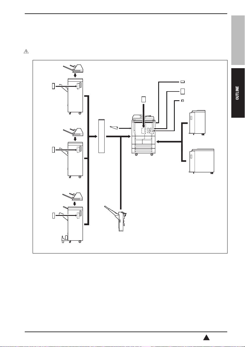
1. SYSTEM CONFIGURATION
A. System configuration
[7]
[8]
[9]
[7]
[8]
[10]
[7]
[8]
[6]
[15] [1]
[2]
[16]
bizhub 750/600
[12]
[13]
[14]
[3]
[4]
[5]
[11]
[1] Main body [9] 50 sheet staple flat stapling finisher (FS-504)
[2] Double sided original auto feeder (DF-604) [10]
[3] Volume paper feed tray (LU-401) [11] Stitch-and-fold finisher (FS-602)
[4] Volume paper feed tray (LU-402) [12] Key counter
[5] Paper exit tray with offset function (SF-601) [13] Local connection kit (EK-701)
[6] Z-folding puncher (ZU-601/ZU-602) [14] Image controller (IC-202)
[7] Torque limiter separation type sheet feeder
(PI-501)
[8]
FS self-contained puncher (PK-502/PK-503/PK-
504/PK-505)
100 sheet staple flat stapling finisher (FS-505)
[15] Paper exit tray
[16] Hard disk (HD-503)
57aat1c001nb
1
1
 Loading...