

Page 1

2
ADJUSTMENT
2 ADJUSTMENT
Page 2

2 ADJUSTMENT
Page 3

HOW TO USE THIS SEC-
ADJUSTMENT
ADJUSTMENTS MADE
TION
[1] Scope and Precautions
This section provides detailed information about the
adjustment items and procedures. Before addressing
customer complaints, perform the following checks:
1. Check whether the power supply voltage meets
the specifications.
2. Check whether the power supply is properly
grounded.
3. Check whether this machine shares the power
supply with any other machine that draws large
current intermittently (e.g., elevator and air conditioner that produce electrical noise).
4. Check whether the installation environment is
good.
a. The machine must be installed in a properly ven-
tilated area not exposed to high temperature,
high humidity, and direct sunlight.
b. The machine must be installed on the horizontal
floor.
5. Check whether original has a problem to cause
the defective image.
6. Check whether the selected density value is correct.
7. Check whether the surface of the platen glass
and the slit glass are clean.
8. Check whether correct paper is used for copying.
9. Check whether copying materials and parts
(e.g., developer, drum, and cleaning blade) are
replenished and replaced when they reach the
end of the useful life.
10. Check whether toner remains.
When servicing the machine, observe the following
precautions:
1. Only either side of the AC line is shut off when the
SW1 (main) of this machine is turned off. Always
unplug the power cord before starting the service
work. If it is necessary to service the machine
with the power on, take care not to be caught in
the scanning gear of the exposure unit.
2. Special care should be taken when handling the
fixing unit because it operates at extremely high
temperatures.
3. The developing unit has a strong magnetic field.
Keep watches and measuring equipment away
from it.
4. Take care not to damage the drum with tools and
so on.
5. Do not touch IC pins with bare hands.
WHEN REPLACING
PARTS
Adjustments (including checks) and settings are not
only required when a customer complaint about the
copy image quality is received, but also after replacing
or reassembling parts.
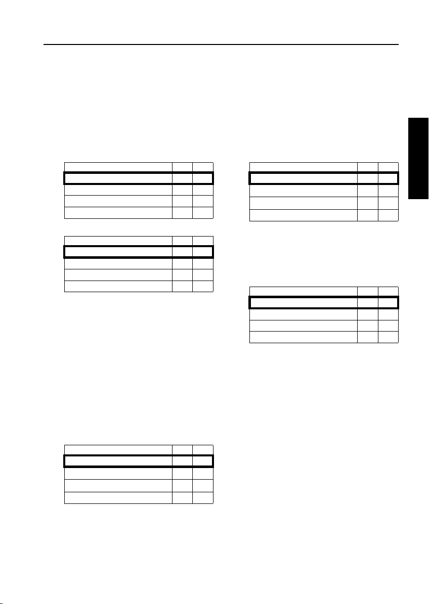
[1] How to Read Tables
Components of the tables used in this section are as
follows:
1. Mode
Adjustment mode to be selected.
[P]: Utility mode
[25]: 25 mode
[36]: 36 mode
[47]: 47 mode
2. Code
Code and copy quantity setting button used in
each mode.
3. Page
Page in the "ADJUSTMENT" section.
4. Circled numbers
2
1
Indicate that adjustments (including
checks) must be made in order of precedence.
(Circle without numeric character):
Indicates that adjustments (including
checks) can be made independently.
2 ADJUSTMENT
2-1
Page 4
ADJUSTMENT
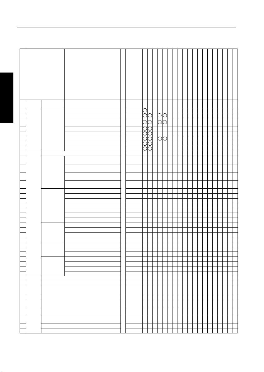
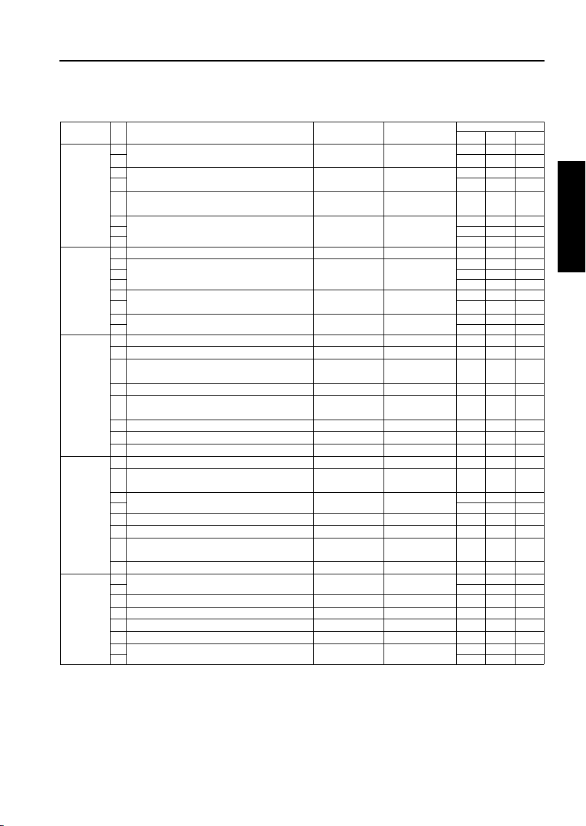
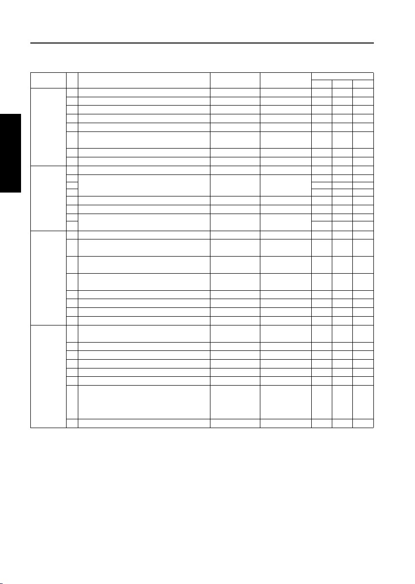
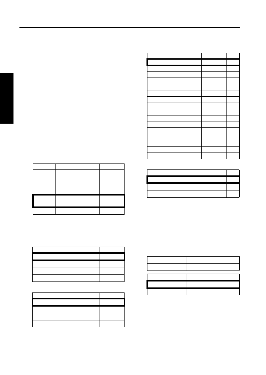
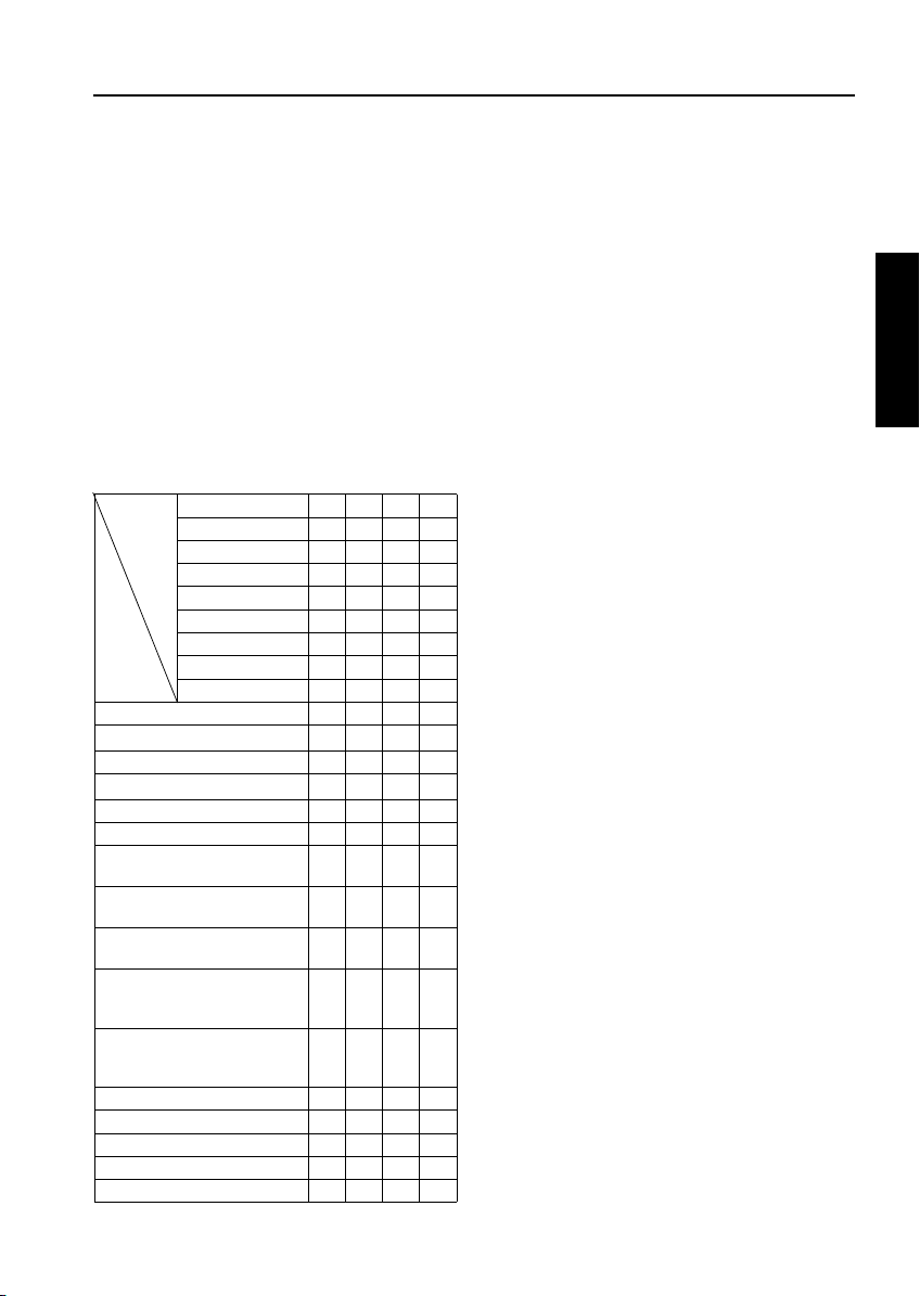
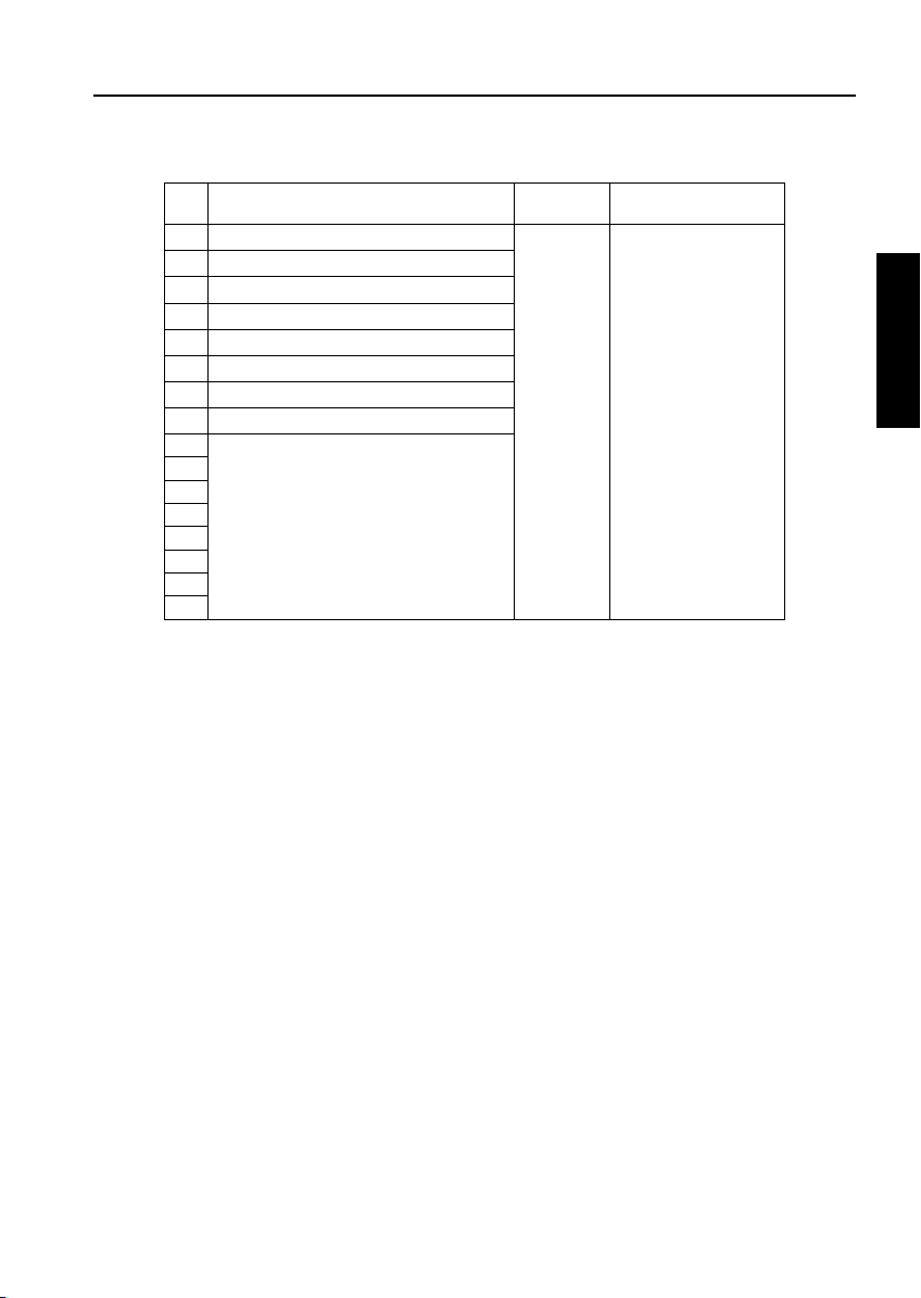
LIST OF ADJUSTMENT ITEMS
Item No.
Process
1
Adjustment
2Drum
2 ADJUSTMENT
3
4
5 Auto dot diameter adjustment 2-53
6 LD1 offset adjustment 2-53
7
8
9
10 Image
Adjust-
11
ment
12
13
14
15 Timing Adjust16 Printer resist loop adjustme nt 2-63
17 Printer pre-resist adjustment 2-63
18 Printer lead edge timing adju stment 2-64
19 Scanner restart timin g adjustment 2-64
20 EDH restart timing adjustment 2-65
21 EDH resist loop adjustment 2-65
22 EDH Adjust23 EDH original size adjustment 2-67
24 EDH sensor sensitivity adjustment 2-67
25 EDH skew offset adjustment 2-68
26 Centering
27 Scanner centering adjustme nt 2-69
28 EDH centering adjustment 2-70
29 Warp adjust30 Scanner (platen) warp (sub-scan) 2- 70
31 Scanner (EDH) warp (ma in scan) 2-70
32 Scanner (EDH) warp (sub-sc an) 2-70
33 Finisher
Adjust-
34 Folding stopper adjustment (FN-7 only) 2-81
ment
35
36 Trimmer stopper adjustment (TMG-2 only) 2-82
37
38
39
40 1st folding position adjustment (ZK-2 only) 2-84
41 2nd folding position adjustment (ZK-2 only) 2-84
Classification by Adjustment
High voltage
adjustment
Peculiarity
Adjustment
Tray Adjustment 2-58
Magnification
Adjustment
ment
ment
Adjustment
ment (Copier)
Stapling and folding stopper adjustment (FN-7 only) 2-81
Cover sheet tray size adjustment
(Cover Inserter C only)
Punch vertical position adjustment
(PK-3 / ZK-2 only)
Punch horizontal position adjustment
(PK-3 / ZK-2 only)
Punch registration loop adjustment
(PK-3 / ZK-2 only)
High Voltage Auto Adjustment
Blade setting mode 2-51
Auto drum potential adjustment
Auto maximum density adjustment
(Dmax adjustment)
LD2 offset adjustment
Auto Gamma Adjustment
Cartridge set mod e
Printer vertical magnification adjustment
Printer horizontal magnification
adjustment
Scanner (platen) vertical adjustment
Scanner (EDH) vertical magnification adjustment
Printer restart timing ad justment 2-62
EDH density adjustment 2-66
Printer centering adjustment 2-69
Scanner (platen) warp (ma in scan) 2-70
Adjustment Item
Mode
Page
Drum
Developer
High Voltage unit
Write unit
Dust-proof glass
Each tray unit
Bypass paper feed unit
Paper up/down plate hoist wires
Tray pick-up solenoid
Registration roller
Registration unit
Registration Clutch
Mis-centering detection sensor
ADU unit
Read unit
Fixing unit
Memory board
EDH unit
2-50
2-52
2-52
2-54
2-56
2-56
2-59
2-60
2-60
2-61
36
2-82
2-83
2-83
2-84
OO
1
2 2 2 2
3 3 1 1
4 4
5 5
6 6 3 3
7 7
8 1
OO O
OO O
OO
OO
OOO
O OOO O
OO
OOO
OOO
OO
OOO
Finisher
O
O
O
O
O
O
O
O
O
O
O
O
O
OO
OO
O
O
O
O
OO
OO
OO
OO
OO
OO
OO
OO
OO
2-2
Page 5
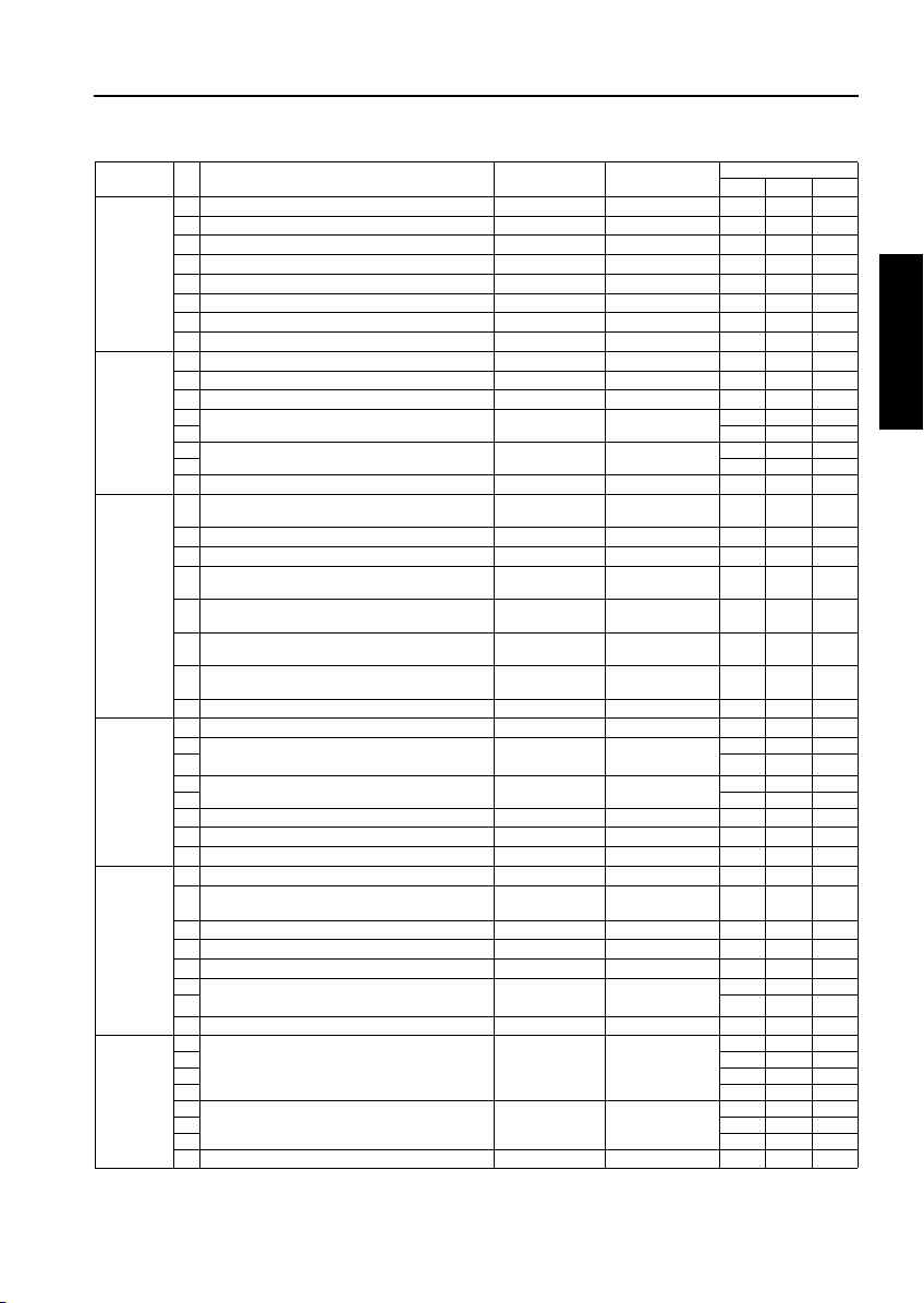
ADJUSTMENT
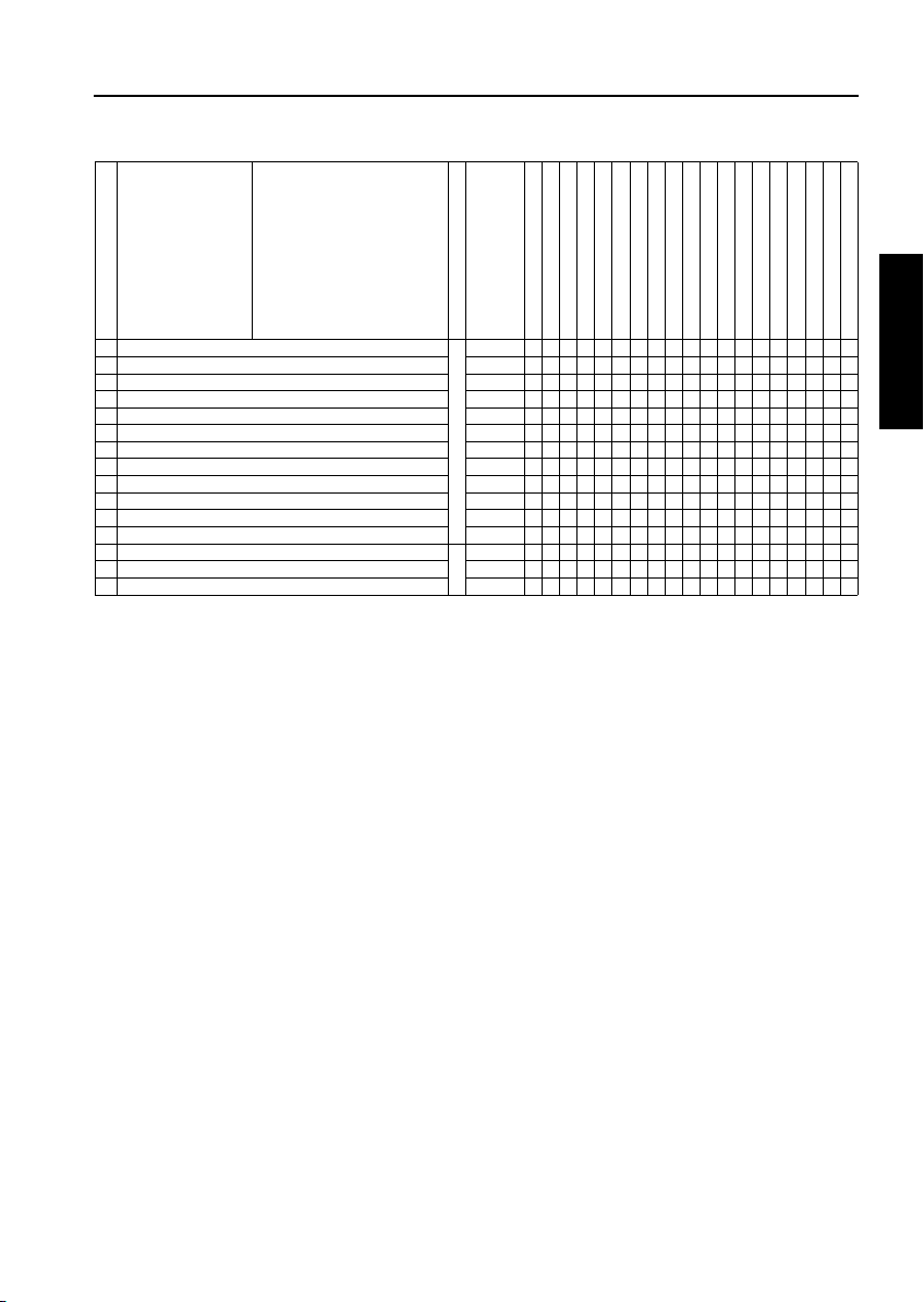
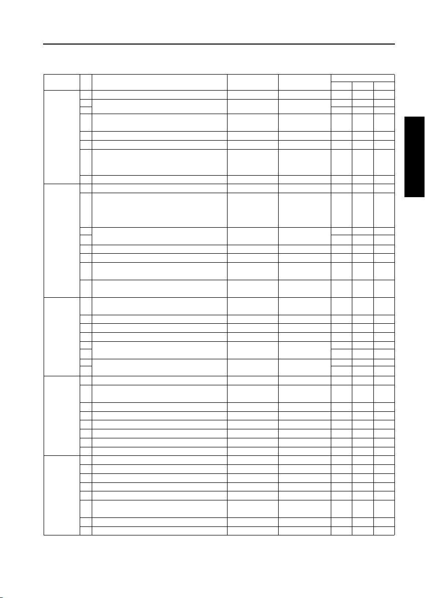
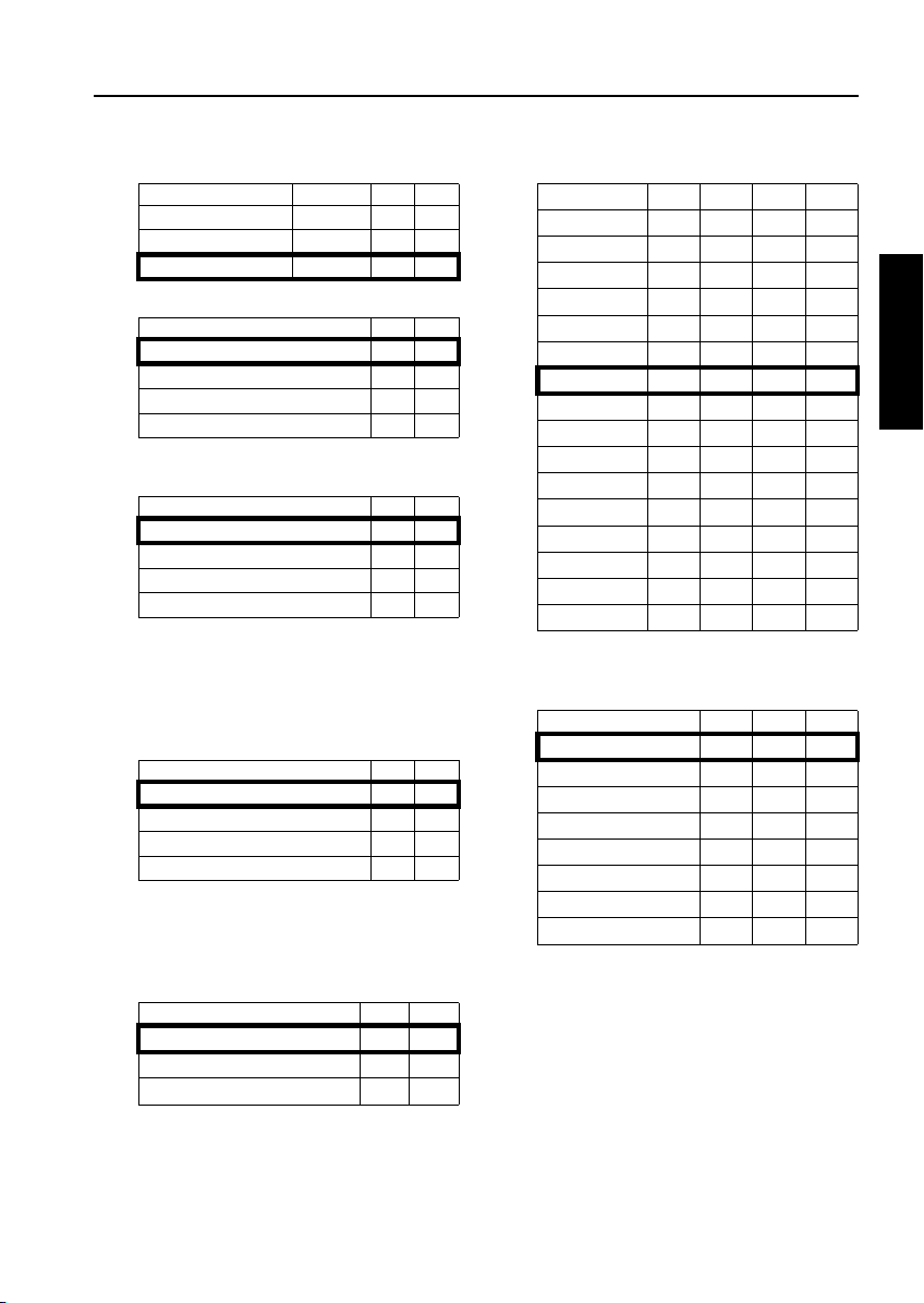
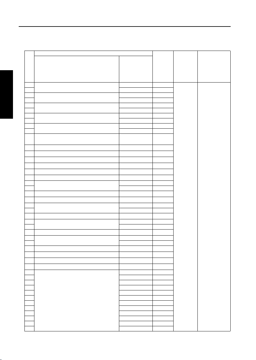
Item No.
42 Centering Adjustment 2-101
43 Paper up/down plate horizontal adjustment 2-105
44 Skew Adjustment 2-107
45 Tray Spring Pressure Adjustment 2-109
46 Paper Feed Height (Upper Limit) Adjustment 2-111
47 Pick-up Release Amount Adjustment 2-113
48 Alignment with drive unit 49 AC and DC drawer positioning 50 ADU gate gap adjustment 51 EDH Mounting Position Adjustment 2-115
52 EDH Hinge Spring Pressure Adjustment 2-118
53 EDH Skew Adjustment 2-116
54 Drum count reset
55 Fixing cleaning web count reset 2-40
56 Developer count reset 2-40
Classification by Adjustment
Adjustment Item
Mode
Page
Drum
Developer
High Voltage unit
Write unit
Dust-proof glass
Each tray unit
Bypass paper feed unit
Paper up/down plate hoist wires
Tray pick-up solenoid
Registration roller
Registration unit
O
O
2-40
25
O
O
Caution: Replacing the image control board
• When a damaged image control board is replaced, the memory board on this board must be used on
the new image control board.
Only when the memory board is damaged, use a new memory board. Since the new memory board
does not have adjustment data, the above adjustments are required. Before making the above adjustments, make the “47-92(output)” setting to make the new memory board effective.
• After making any adjustment, make the “47mode-96(output) setting”. After made the “47mode-96(output)” setting, the adjustment data is saved.
• However, the “47mode -92” and -96" settings are protected to prevent them from careless operation.
In order to make “47mode -92” and -96" settings using the saved adjustment data, the protection must
be disabled. For the unprotection method, contact the service section of the authorized distributor.
Registration Clutch
Mis-centering detection sensor
ADU unit
Read unit
Fixing unit
Memory board
EDH unit
Finisher
2 ADJUSTMENT
O
O
O
O
O
2-3
Page 6

ADJUSTMENT
LCD ADJUSTMENT
[1] Control Panel Adjustment
Enter the key operator mode and select " Touch
panel adjustment" to adjust the LCD touch panel.
*If you cannot select the touch panel adjustment
mode after entering the key operator mode
because the touch panel is displaced absolutely,
press numeric keys to select " Touch panel
adjustment".
2 ADJUSTMENT
[2] LCD Panel Contrast/Key Sound
Adjustment
Enter the key operation mode and select " LCD
Panel contrast/Key sound adjustment" to adjust the
contrast, backlight, and/or buzzer as desired.
10
SETTINGS AND
ADJUSTMENTS MADE
10
WITH THE UTILITY
FUNCTION
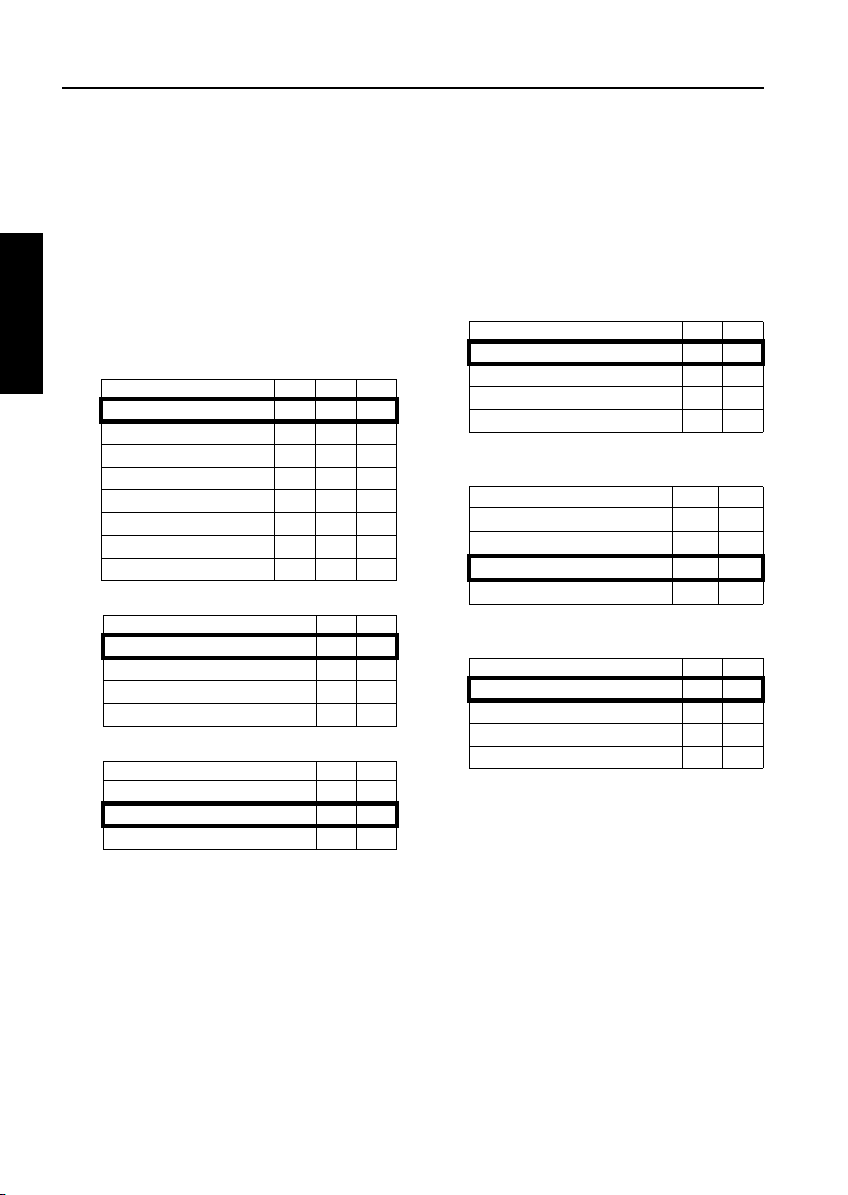
The Utility function allows you to perform following
numerical value checks using the Utility key:
1. Total counter
2. Copier counter
3. Printer counter
4. * PM counter
7
5. Density Shift (Auto <Text/Photo>)
6. Density Shift (Increase Contrast)
7. Density Shift (Photo)
8. Density Shift (Text)
* PM counter is only displayed when Check
key is pressed on the counter list view screen.
!
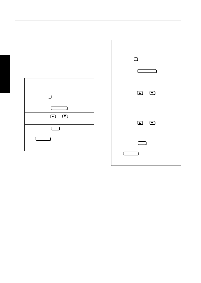
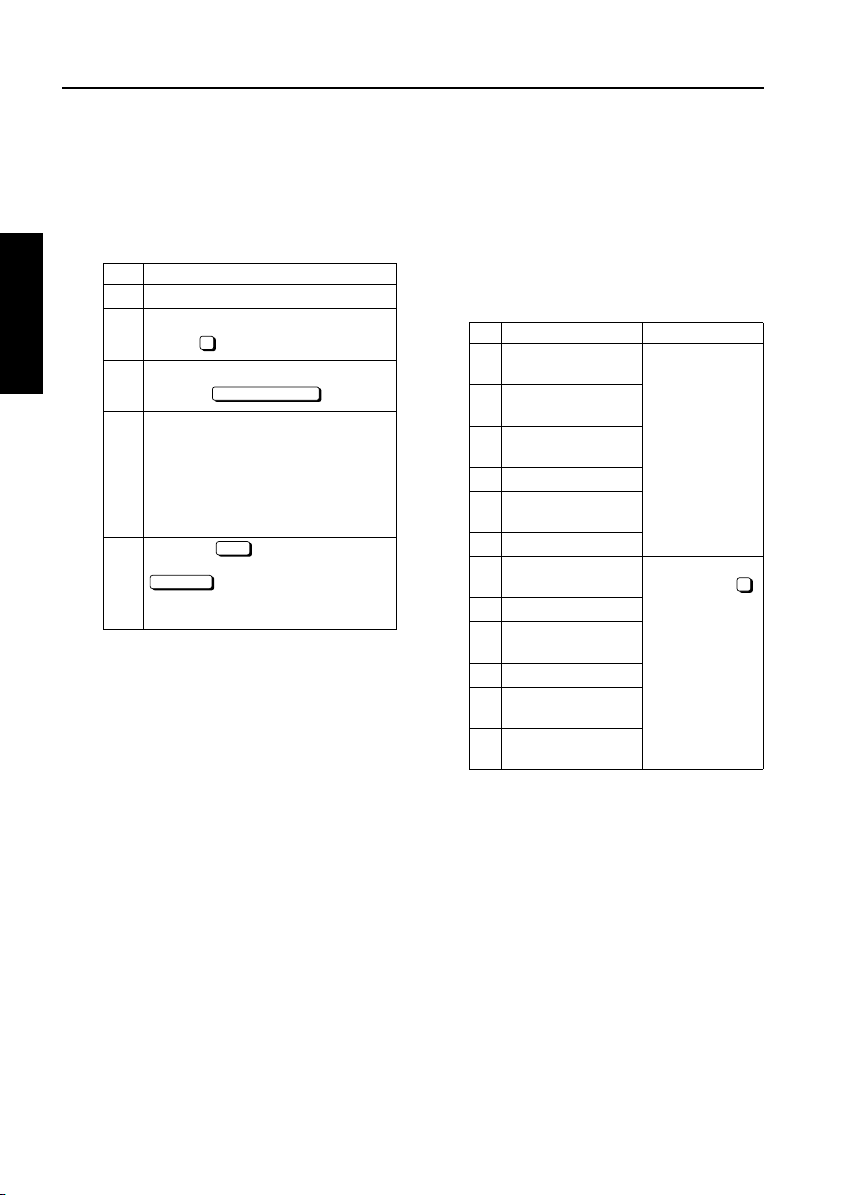
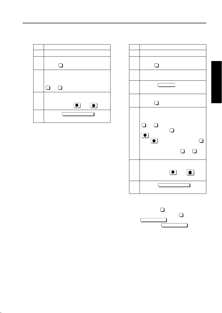
[1] Checking and Printing the Utility
function
1. Turn ON the main switch.
2. Press the Utility key.
3. Counter list is displayed.
4. Press the key.
5. Press the START button to print out the counter
list. The Utility function is cancelled automatically.
6. If the counter list need not be displayed, press
the key.
COUNTER MENU
EXIT
[2] Setting up the Utility function
1. Turn ON the main switch.
2. Press the key.
3. Press the Text/Photo ENHANCE key to set the
density shift, then press the Utility key.
4. Enter a value (0-5) with a numeric key, then press
the key. The smaller the value, the darker
the density.
5. Press the key to return to the Basic
screen.
OK
SPECIAL
ORIGINAL
OK
2-4
Page 7
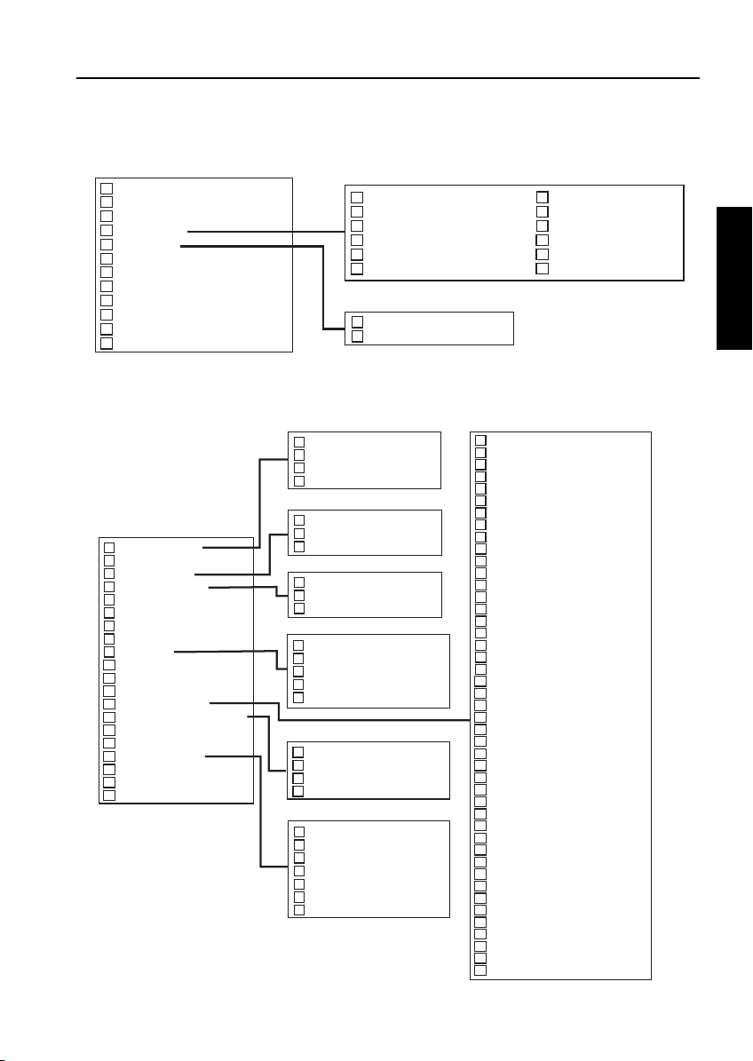
MODE CHANGING MENU
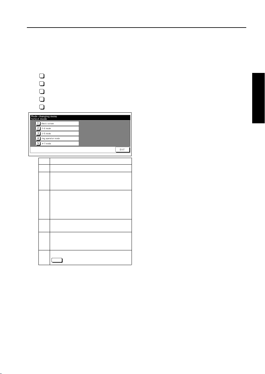
[1] Mode Selection
You can select a mode from the following [Mode changing menu: [Select mode] without turning OFF and ON
the power switch.
1
Basic screen
2
3-6 mode
3
2-5 mode
4
Key operation mode
5
4-7 mode
Step Operation
Turn on the main switch.
1
Press Utility key and wait until [Enter
password for mode selection] message
2
appears.
Enter the password 9272 and press the
Start button.
Note that this password is fixed and can-
3
not be changed.
The [Mode changing menu] appears.
Enter the number to select the desired
4
mode.
To return to the [Mode changing menu],
press Utility key and wait until the menu
5
appears again.
Upon completion of the adjustment, press
6
EXIT
key to return to the Basic screen.
ADJUSTMENT
2 ADJUSTMENT
2-5
Page 8
ADJUSTMENT
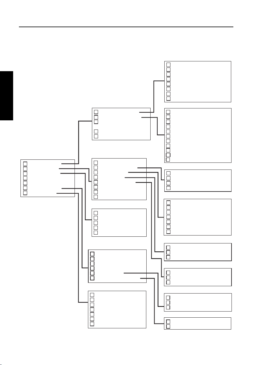
[2] Display transition of 36 modes
x : Factory exclusive use. Service is not used.
2 ADJUSTMENT
3-6 Modus / Adjustment mode
1 Process adjustment
2 Image adjustment
3 Running test mode
4 Test pattern output mode
5 Test pattern density setting
6 Finisher adjustment
7 List output mode
Process adjustment mode menu
1 High voltage adjustment
2 Drum peculiarity adjustment
3 Drum peculiarity adjustment
(hand op) x
4 User paper setting
5 Recall standard data
Image adjustment mode menu
1 Tray adjustment
2 Magnification adjustment
3 Timing adjustment
4 EDH adjustment
5 Centering adjustment
6 Warp adjustment (Copier)
7 Non-image area erase check
8 Recall standard data
Running test mode menu
1 Intermittent copy mode
2 Paperless running mode
3 Paperless mode
4 Paperless endless mode
5 Running mode
Finisher adjustment mode menu
1 Stapling&Folding stopper adjustm.
2 Folding stopper adjustment
3 Cover sheet tray size adjustment
4 Trimmer stopper adjustment
5 Punch adjustment
6 Z-Folding position adjustment
List output mode menu
1 Machine management list 1
2 Adjustment data list
3 Black ratio data list
4 Machine management list 2
5 Parameter list
6 Memory dump list
7 Font pattern
High voltage adjustment mode menu
1 High voltage auto adjustment
2 HV adjustment (Transfer) x
3 HV adjustment (Transfer) x
4 HV adjustment (Separation-AC) x
5 HV adjustment (Separation-DC) x
6 HV adjustment (Charging grid voltage) x
7 HV adjustment (Bias of development) x
8 Transfer guide confirm x
Drum peculiarity adjustment mode menu
1 Blade setting mode
2 Auto drum potential adjustment
3 Auto maximum density adjustment
4 Auto dot diameter adjustment
5 LD 1 offset adjustment
6 LD 2 offset adjustment
7 LD 1 bias adjustment x
8 LD 2 bias adjustment x
9 LD sub-pitch offset adjustment x
10 Auto gamma adjustment(1dot)
11 Cartridge set mode
Magnification adjustment mode menu
1 Printer drum clock adjustment
2 Printer horizontal adjustment
3 Scanner drum clock adjustment
4 EDH drum clock adjustment
Timing adjustment mode menu
1 Printer restart timing adjustment
2 Printer resist loop adjustment
3 Printer pre-resist adjustment
4 Printer lead edge timing adjustment
5 Scanner restart timing adjustment
6 EDH restart timing adjustment
7 EDH resist loop adjustment
EDH adjustment mode menu
1 EDH density adjustment
2 EDH original size adjustment
3 EDH sensor sensitivity adjustment
Centering adjustment mode menu
1 Printer centring adjustment
2 Scanner centring adjustment
3 EDH centring adjustment
Punch adjustment mode menu
1 Punch vertical position adjustment
2 Punch horizontal position adjustment
3 Punch resist loop adjustment
Z-folding position adjustment mode menu
1 1st Z-holding position adjustment
2 2nd Z-holding position adjustment
2-6
Page 9
[3] Display transition of 25 modes
ADJUSTMENT
2-5 Modus /Memory setting mode
1 Software SW setting
2 Paper size setting
3 PM count
4 Data collection
5 Parts counter
6 Password setting
7 Telephone number setting
8 M/C serial number setting
9 Indication of ROM version
10 RD mode setting
11 ISW
12 Setting date input
Collecting data menu
1 Total count of each paper size
2 Copy count of each paper size
3 Print count of each paper size
4 EDH count
5 Black ratio of each sction
6 Black ratio ranking list
Copy count of part menu
1 Count of special parts
2 Count of each parts
[4] Display transition of Key Operation modes
System initial setting menu
1 Date & Time setting
2 Language select setting
3 IP adress setting / Tandem
4 E-mail transmission setting
User setting mode menu
Key operator mode menu
1 System initial setting
2 Copier initial setting
3 User setting mode
4 E.K.C function setting
5 Lock / delete program memory
6 Paper type / Special size set
7 Panel contrast / Key sound adj.
8 Key operator data setting
9 Weekly timer
10 Control panel adjustment
11 Tray auto select setting
12 Energy saver setting
13 Memory switch setting
14 Machine management list print
15 * Not use Minolta!
16 Side 2 lens adjustment
17 Finisher adjustment
18 HDD management setting
19 Scanner transmission setting
20 Non-image area erase setting
*1 Name of system
E.K.C : Except USA area
E.C.M : USA area only
1 User density level 1setting
2 User density level 2 setting
3 User lens mode ratio setting
Enter E.K.C Master code: *1
1 E.K.C data edit
2 E.K.C all count reset
3 E.K.C function setting
Weekly timer setting menu
1 Weekly timer ON/OFF setting
2 Timer setting
3 Timer action ON/OFF setting
4 Lunch hour off setting
5 Timer interrupt password set
Management list print mode menu
1 Program memory list
2 User management list
3 E.K.C. management list
4 Font pattern list
Finisher adjustment mode menu
1 Stapling & Folding stopper adjust.
2 Folding stopper adjustment
3 Trimmer stopper adjustment
4 Punch adjustment
5 Z-Folding position adjustment
6 Three-Folding position adjustment
7 2-Positions staole pitch adjustment
7 JAM data of time series
8 JAM count
9 Count of each copy mode
10 SC count
11 JAM count of each section
12 SC count of each section
Memory switch menu
1 Panel reset timer
2 Panel reset key function
3 EDH-Original effect
4 Program memory auto recall -305 Finisher mode by Full-Auto
6 Initial by Key Counter insert
7 Erasure outside area of original
8 EDH frame erasure selection
9 Automatic tray switching
10 Platen APS
11 EDH APS
12 Platen AMS
13 EDH AMS
14 Select tray when APS cancel
15 Platen original size detect
16 EDH original size detect
17 Platen original size detect (SMALL)
18 Rotation
19 Staple mode reset function
20 Job offset operating
21 Continuation print
22 SDF auto start
23 Key click sound
24 1 Shot indication time
25 Power save screen
26 Start Key latch function
27 Stop Key function
28 Auto select of booklet copy
29 E.K.C. Password
30 Arrow key change [Image shift]
31 Exit direction of 1 sheet
32 An interruption suspended way
33 E.K.C. password input timing
34 Key click sound (No paper/ Jam)
35 Reserve copy function
36 Scan stop by pull out tray
37 Change page no. Pos. (booklet)
38 Trimmer (Std./ Non Std size)
39 Timer which prohibits print
40 Bookmark fanction
41 Delete of overlay image
42 Orig. direction/binding mode
43 Image stored conti. (SRV)
44 Image recalled conti. (SRV)
45 Exit direction
2 ADJUSTMENT
2-7
Page 10
ADJUSTMENT
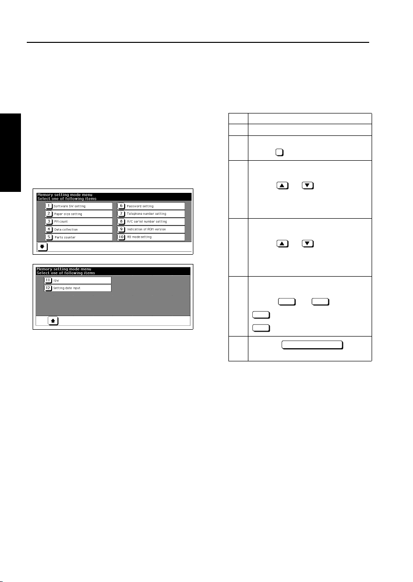
25 MODE
[1] Setting the 25 Mode
This machine has an adjustment mode called the "25
Mode". Select this mode to rewrite data in the non-volatile memory or make various settings.
1. Turn OFF the main switch.
2. While pressing the copy quantity setting buttons
2 and 5, turn ON the main switch.
The 25 Mode Menu screen will appear.
Now the machine is in the 25 mode, disabling
normal copy operations.
2 ADJUSTMENT
[25 Mode Menu. Screen]
3. Press the numeric button of the desired setting
item.
The associated setting screen will appear.
4. Enter data in the setting screen.
5. Turning OFF the main switch cancels the 25
mode.
6. New data will take effect after restart.
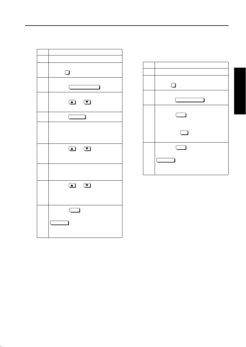
[2] Setting Software DIP Switches
1. Procedure
Bring up the Software DIP SW Setting screen
and set software DIP switches.
Step Operation
Enter the 25 mode.
1
[Memory setting mode menu]
2
Select " Software DIP SW setting".
1
Software switch setting mode 05
Select a DIP switch number.
Use the or key at the left.
3
To use numeric keys, invert the DIP
switch number at the left before entering
a DIP switch number.
Select a bit number of the selected DIP
switch.
Use the or key at the right.
4
To use numeric keys, invert the bit number at the upper center before entering a
DIP switch number.
Select ON (=1), or OFF (=0) of the
switch.
Use the or key.
5
Press the key to
6
return to the 25 Mode Menu. Screen.
ON OFF
: Sets 1.
ON
: Sets 0.
OFF
PREVIOUS SCREEN
2-8
Page 11
ADJUSTMENT
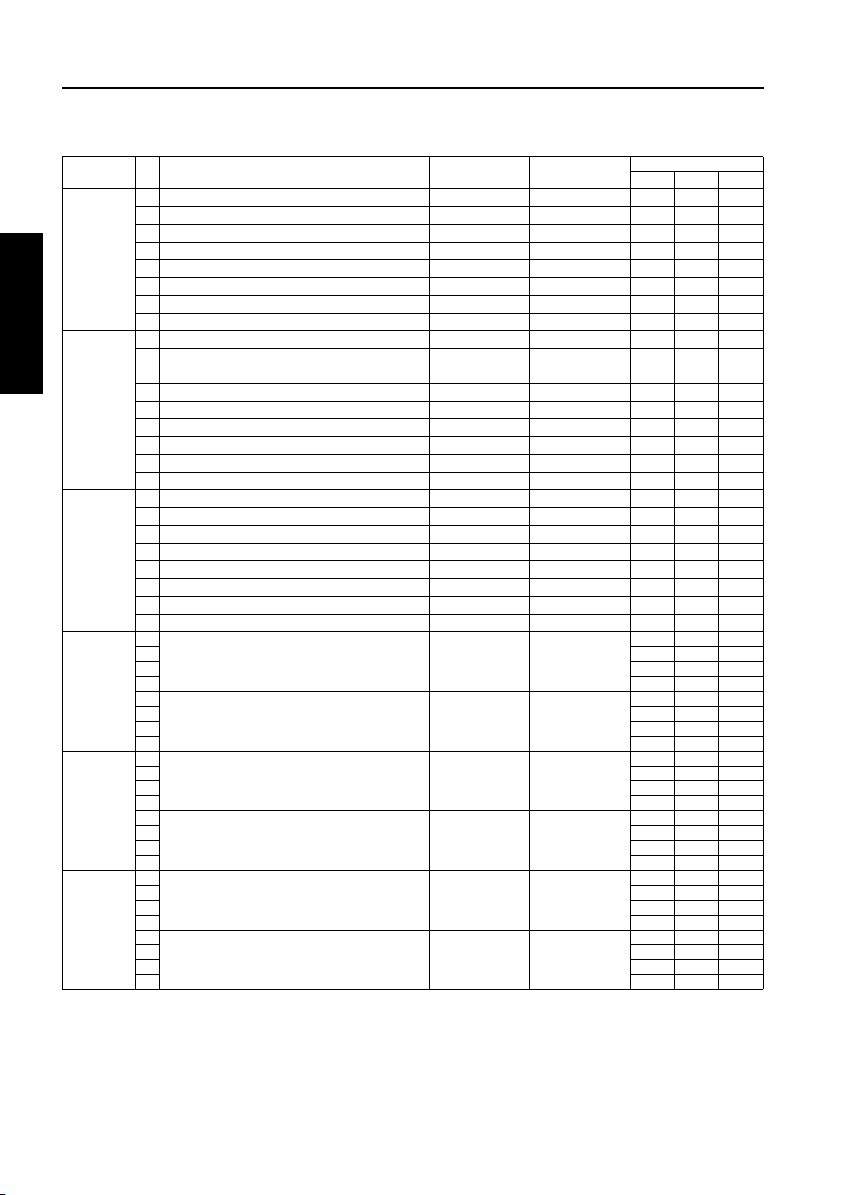
< List of Software Switches >
DIPSW
No.
DIPSW 1
DIPSW2
DIPSW3
DIPSW4
DIPSW5
Note1:
Bit Function 0 1
0 Condition for stopping copying after indica-
tion of toner supply
1 000
2 Method for stopping copying after indica-
tion of toner supply
3 000
Inhibition of copying when PM count is
4
reached
5
Number of copies made before inhibition of
6 000
copying when PM count is reached
7 000
Hard disk connection
0
1
Electrode cleaning cycle (when power is
2 000
turned ON)
3 000
4 Electrode cleaning cycle (after power is
turned ON)
5 000
6
Blade automatic switching cycle
7 000
Regular toner supply amount
0
SC latch
1
25, 36, 47 mode password request (pass-
2
word: 9272)
Charging corona unit cleaning function
3
Transfer /separation corona unit cleaning
4
function
Movement of blade to transportation
5
47 mode 15-01 data collection clearing
6
-
7
ADF automatic skew adjustment
0
Inhibition of thick paper / double sided copy
1
paper mode
2
Destination selection
3 001
Key counter removal recovery
4
Inhibition of magnified APS
5
Fixed magnification rate setting change in
6
key operator mode
A3 (11x17) counting method
7
0
Toner concentration threshold
1 000
- - -
2
-
3
- - -
4
-
5
6
2 dot PWM density in photo mode
7 000
* 1 * 1
* 2 * 2
Not Inhibited Inhibited 0 0 0
* 3 * 3
Disconnected Connected 0 0 0
* 4 * 4
* 5 * 5
* 6 * 6
* 7 * 7 0 0 0
Unlatched Latched 0 0 0
Not requested Requested 0 0 0
ON OFF 0 0 0
ON OFF 0 0 0
Disabled Enabled 0 0 0
Disabled Enabled 0 0 0
- -000
Enabled Disabled 0 0 0
Disabled Enabled 0 0 0
* 8 * 8
Disabled Enabled 0 0 0
Enabled Disabled 0 1 0
Enabled Disabled 1 0 0
Increments of 1 Increments of 2
* 9 * 9
- -000
- -000
* 10 * 10
Initial Value
Japan Inch Metric
111
111
000
000
000
000
010
000
000
000
000
000
This bit is used to keep the cleaning blade off the drum to protect the drum and cleaning blade during transportation
of the main body.
To keep the blade off the drum, set this DIP switch to 1, open the front door to turn OFF the interlock, and start
up the 47 mode. The blade switching operation is performed at this time. If blade 1 is used, do not forget blade
charge and 36 mode blade set mode at reinstallation. This DIPSW will be reset to 0 automatically.
2 ADJUSTMENT
2-9
Page 12

ADJUSTMENT
DIPSW
DIPSW 6
2 ADJUSTMENT
DIPSW 7
DIPSW8
DIPSW 9
DIPSW10
DIPSW11
Note 2: This bit determines whether drum potential adjustment is to be made using a drum potential sensor.
Bit Function 0 1
No.
- - -
0
-
1
- - -
2
3 Transfer/separation output for thick paper
4 000
5 Transfer/separation output for thin paper
6 000
Auto drum potential adjustment (Note 2)
7
0 Developing potential control for image area
1 000
-
2
-
3
-
4
-
5
-
6
-
7
-
0
- - -
1
2 Fixing roller initial rotation
3 111
4 Fixing roller initial rotation time setting
5 000
A3(11 × 17) PM counter switch
6
Store on hard disk
7
Operation at key counter removal (copy) Same as stop
0
Operation at key counter removal (Print) Ignored Same as
1
2 Message switching
3 000
4 Copy count limit
5 000
6 000
7 000
0 Page memory allocation at power on Ditto.
1 000
Page memory allocation at job starts
2
-
3
-
4
-
5
-
6
-
7
-
0
-
1
-
2
SC/E code screen switchover
3
Selection of filter for jagged edges on slant-
4
ing lines
Gradation switchover in Photo mode 2bitED-2dot
5
-
6
JAM indication screen type Without Jam
7
- -000
* 11 * 11
* 12 * 12
Enabled Disabled 0 0 0
* 13 * 13
- -000
- -000
- -000
- -000
- -000
- -000
- -000
* 14 * 14
* 15 * 15
1 count 2 count 0 0 0
Enable Disable 0 0 0
Immediate stop
key
(JAM)
DIPSW9-0
* 16 * 16
* 17 * 17
* 18 * 18
* 19 * 19 0 0 0
- -000
- -000
- -000
- -000
- -000
- -000
- -000
- -000
Switched
Not switched
(All are F codes)
Not selected Selected 0 0 0
1bitED-2dot
PWM
PWM
- -000
code
With Jam code 0 0 0
Initial Value
Japan Inch Metric
000
000
000
000
000
000
000
011
0 0 0
000
000
000
000
000
000
This setting is used to check whether an image problem has been caused by a faulty drum potential sensor.
2-10
Page 13
ADJUSTMENT
DIPSW
No.
DIPSW 12
DIPSW 13
DIPSW14
DIPSW15
DIPSW16
DIPSW17
Bit Function 0 1
Black stripe creation interval
0
-
1
-
2
Printer automatic centering correction
3
High voltage output in 36/47 mode
4
-
5
-
6
-
7
Size detection 1
0
Size detection 2
1
Size detection 3
2
3 Size detection 4
4 010
5 F4 size detection
6 000
-
7
Size detection 5 (main body)
0
-
1
-
2
Size detection 5 (by-pass feed)
3
Size detection 5 (platen)
4
Size detection 5 (ADF)
5
Size detection selection (PI)
6
-
7
-
0
1 Maximum number of sheets that can be
stapled
2 000
3 FNS alarm stop SW
4 000
RD mode connection recognition
5
Dmax. value in printer mode
6
-
7
-
0
Multi-job Reservation
1
-
2
C(K) counting in printer mode
3
TC start date indication (Utility mode)
4
5 Non-original area erasure mode judge-
ment level
6 000
-
7
0 WT summer time setting
1 111
2 111
3 000
4 Density selection for scanning tab paper
5 000
6 000
-
7
Not performed Every 5 copies
- -000
- -000
Enable Disable 0 0 0
Not output Output 1 1 1
- -000
- -000
- -000
A5 5.5 x 8.5 0 1 0
A4R 8.5 x 11R 0 1 0
8.5 x 14 F4 0 0 1
* 20 * 20
* 21 * 21
- -000
B4 : 11 x 17/
B5 : 8.5 x 11
- -000
- -000
B4 : 11 x 17/
B5 : 8.5 x 11
B4 : 11 x 17/
B5 : 8.5 x 11
B4 : 11 x 17/
B5 : 8.5 x 11
B4 : 11 x 17/
B5 : 8.5 x 11
- -000
8K/16K 0 0 0
8K/16K 0 0 0
8K/16K 0 0 0
8K/16K 0 0 0
8K/16K 0 0 0
- -000
* 22 * 22
* 23 * 23
Disconnect Connect 0 0 0
1.43 1.35 0 0 0
- -000
- -000
Reservation
enabled
disabled
- -000
Not counted Counted 0 0 0
Indicated Not indicated 0 0 0
* 24 * 24
- -000
* 25 * 25
* 26 * 26
- -000
Initial Value
Japan Inch Metric
000
000
000
000
000
000
000
000
000
2 ADJUSTMENT
2-11
Page 14
ADJUSTMENT
2 ADJUSTMENT
DIPSW
No.
DIPSW18
DIPSW 19
DIPSW20
DIPSW21
Bit Function 0 1
Tray 1's faulty part isolation
0
Tray 2's faulty part isolation
1
Tray 3's faulty part isolation
2
Tray 4's (LCT's) faulty part isolation
3
ADF faulty part isolation
4
Folding, stapling and folding, trimmer faulty
5
part isolation
PI faulty part isolation
6
Hard disk faulty part isolation
7
-
0
1 Fixing temperature setting switching
2 000
3 000
PZ faulty part isolation
4
PK faulty part isolation
5
6 Sel ection of a default resolution for IP scan-
ner
7 000
Group stapling
0
Original size scanning with shift function
1
(Note1)
Stamp page number switching Based on origi-
2
Keyboard layout ABC layout QWERTY lay-
3
-
4
-
5
-
6
-
7
Mixed sized print stapling inhibition
0
(Print)
LCT size setting in key operator mode
1
Original count display
2
-
3
Output on Tandem
4
Allocation recovery on Tandem
5
Special paper APS response
6
Normal Unavailable 0 0 0
Normal Unavailable 0 0 0
Normal Unavailable 0 0 0
Normal Unavailable 0 0 0
Normal Unavailable 0 0 0
Normal Unavailable 0 0 0
Normal Unavailable 0 0 0
Normal Unavailable 0 0 0
- -000
* 27 * 27
Normal Unavailable 0 0 0
Normal Unavailable 0 0 0
* 28 * 28
Disabled Enabled 0 0 0
Normal Original priority 0 0 0
Based on trans-
nal
fer paper
out
- -000
- -000
- -000
- -000
Enabled (real-
time output)
Disabled (batch
processing)
Disabled Enabled 0 0 0
Displayed Not displayed 0 0 0
- -000
Realtime Batch 0 0 0
Enabled Disabled 0 0 0
Enabled (All
Disabled
except Thick 2
papers and
Initial Value
Japan Inch Metric
000
000
000
000
000
000
Thick 3 papers)
-
7
- -000
Note1:When "Normal" is selected, the original size is compared with the copy paper size and the smaller
one is assumed to be the image area size. When "Original priority" is selected, the original size is
compared assumed to be the image area size only when the image shift mode is selected.
2-12
Page 15
ADJUSTMENT
DIPSW
No.
DIPSW22
DIPSW23
DIPSW24
DIPSW25
DIPSW28
Bit Function 0 1
IP address setting
0
1 Number of punched holes
2 001
Standard position of image on Nonstand-
3
ard size original
Function of Power save button
4
-
5
Operation on staple empty of FNS Requesting
6
-
7
-
0
Output operation when EKC user ID
unmatching
1
Disabled Enabled 0(1) 0(1) 0(1)
* 29 * 29
User selected APS of ADF 0 0 0
Enabled Disabled 0 0 0
- -000
Selectable sta-
staple supply
ple supply or
without stapling
- -000
- -000
Enabled
(counted by
other user
Disabled (registered non-output list)
Initial Value
Japan Inch Metric
010
000
000
2 ADJUSTMENT
account)
2 Image density selection (toner density
selection of developer)
3 000
-
4
-
5
Job memory registration of the special
6
paper setting on the bypass tray
Face-up ejection of the thick paper 2 to
7
sub-tray (Print)
HDD JOB recall operation
0
-
1
-
2
-
3
4 Maximum number of sheets with z-folding
(main tray)
5 111
6 Maximum number of sheets with z-folding +
stapling (main tray)
7 000
-
0
Maximum number of sheets with Booklet
1
Mode
- - -
2
- - -
3
- - -
4
- - -
5
- - -
6
- - -
7
- - -
0
- - -
1
- - -
2
- - -
3
- - -
4
Timing and centring adjustment in key
5
operator mode
- - -
6
- - -
7
* 30 * 30
- -000
- -000
Disabled Enabled 0 0 0
Disabled Enabled 0 0 0
Password
Password + file
name
- -000
- -000
- -000
* 31 * 31
* 32 * 32
- -000
20 sheet 16 sheet
Disabled Enabled 0 0 0
000
000
000
000
000
000
000
000
000
000
000
000
000
000
000
000
000
000
2-13
Page 16
ADJUSTMENT
2 ADJUSTMENT
DIPSW
No.
DIPSW29
DIPSW30
DIPSW31
DIPSW33
DIPSW34
DIPSW35
Bit Function 0 1
- - -
0
- - -
1
- - -
2
- - -
3
- - -
4
- - -
5
- - -
6
- - -
7
- - -
0
25 mode collection data 5-11 for checking Display restric-
1
- - -
2
- - -
3
- - -
4
- - -
5
- - -
6
Passwords to save/access hard disk JOB Not displayed Displayed
7
- - -
0
- - -
1
- - -
2
- - -
3
- - -
4
- - -
5
- - -
6
-
7
0 Normal paper process control switchover
1 000
2 000
3 000
4 Recycled paper process control switchover
5 000
6 000
7 000
0 Colored paper process control switchover
1 000
2 000
3 000
4 Special paper process control switchover
5 000
6 000
7 000
0 High-quality paper process control
1 000
switchover
2 000
3 000
4 Exclusive paper A paper process control
5 000
switchover
6 000
7 000
tion
* 33 * 33
* 33 * 33
* 33 * 33
* 33 * 33
* 33 * 33
* 33 * 33
No display
restriction
- - 000
Initial Value
Japan Inch Metric
000
000
000
000
000
000
000
000
000
111
000
000
000
000
000
000
000
000
000
000
000
000
000
000
000
000
000
000
000
2-14
Page 17
ADJUSTMENT
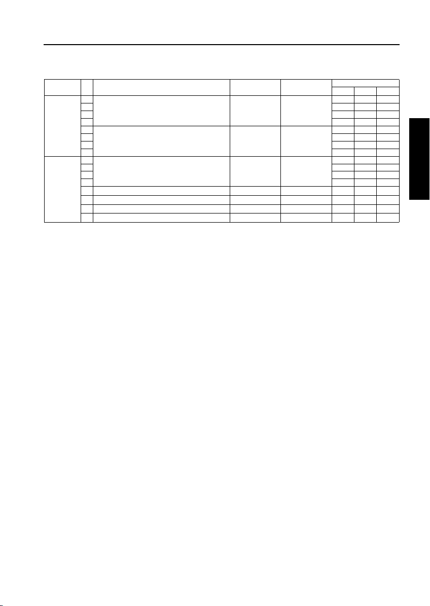
DIPSW
No.
DIPSW36
DIPSW37
Bit Function 0 1
0 Exclusive paper B paper process control
1 000
switchover
2 000
3 000
4 Exclusive paper C paper process control
5 000
switchover
6 000
7 000
0 Exclusive paper D paper process control
1 000
switchover
2 000
3 000
- - -
4
- - -
5
- - -
6
-
7
* 33 * 33
* 33 * 33
* 33 * 33
- - 000
Initial Value
Japan Inch Metric
000
000
000
000
000
000
2 ADJUSTMENT
2-15
Page 18

ADJUSTMENT
*1 Condition for stopping copying after indication of
toner supply request
Mode 1-1 1-0
Stops after printing 1,500 copies
Stops after printing 3,000 copies
Stops after printing 4,000 copies
Stops after printing 5,000 copies
*2 Method for stopping copying after indication of
toner supply request
2 ADJUSTMENT
Mode 1-3 1-2
Stops after ejecting the paper
remaining in the machine
Stops after printing specified number of copies
Stops at the end of the current job
Does not stop
*3 Number of copies made before inhibition of copy-
ing when PM count is reached
Mode 1-7 1-6 1-5
1,000 copies
2,000 copies
3,000 copies
4,000 copies
5,000 copies
1,000 copies
1,000 copies
1,000 copies
000
001
010
011
100
101
110
111
*4 Electrode cleaning cycle (fixing temperature is
50°C or lower when power is turned ON)
Mode 2-3 2-2 2-1
When power is turned ON
5,000 copies
10,000 copies
15,000 copies
20,000 copies
25,000 copies
30,000 copies
Not cleaned
000
001
010
011
100
101
110
111
00
01
10
11
00
01
10
11
*5 Electrode cleaning cycle (after power is turned
ON)
Mode 2-5 2-4
10,000 copies
30,000 copies
40,000 copies
50,000 copies
00
01
10
11
*6 Blade automatic switching cycle
Mode 2-7 2-6
250,000 copies
300,000 copies
400,000 copies
500,000 copies
00
01
10
11
*7 Regular toner supply amount
When copying the original which black ratio is low
(less than 1 %), gray background image is
caused because the toner density of developer
increases. In this case, changing this bit to 1,
decreases the amount of toner supplied regularly, thus preventing gray background image.
Note: When copying the original which black
ratio is normal, changing this bit to 1
causes the image to be lighter.
Mode 3-0
Standard
Decrease regular toner supply amount
0
1
*8 Destination selection
Mode 4-3 4-2
Japan
Inch area
Metric area
00
01
10
2-16
Page 19
ADJUSTMENT
*9 Toner concentration threshold
This bit sets the read level of the toner concentration patch formed on the drum to determine
the toner concentration. The setting can be
made by shifting the threshold of black color to
the positive or negative side.
• Standard -3: The image becomes darker.
• Standard +3: The image becomes lighter.
• Standard +5: The image becomes far lighter.
Mode 5-1 5-0
Standard
Standard -3
Standard +3
Standard +5
00
01
10
11
*10 2 dot PWM table in photo mode
Mode 5-7 5-6
Standard
Light
Dark
Not use
00
01
10
11
*11 Transfer/separation corona unit output for thick
paper
This bit is used when “Thick 1”, “Thick 2” or “Tab
paper” is selected for “Paper type/special size
setting” in the key operator mode.
When “No specification” is selected, data for
“Thick 1:170 g/m
2
” or “Thick 2: 200 g/m2” is used
(the data for “Thick 2” is also used for tab paper).
When other than “No specification” is selected,
the selected output data is used for both “Thick 1”
and “Thick 2.”
When this bit cannot be used with "Thick 2"
selected, "Thick 3" can be selected in the key
operator mode.
(Changing DIP SW is not required.)
Mode 6-4 6-3
No specification
2
paper
200 g/m
2
170 g/m
paper
Postcard
00
01
10
11
*12 Transfer/separation corona unit output for thin
paper
This bit is used when "Thin" is selected for "Paper
type/special size setting" in the key operator
mode.
When "No specification" is selected, the output
data by destination (
: 16lb, paper,
area
Japan
: 50 g/m2 paper,
Metric area
: 60 g/m2 paper) is
Inch
used.
Mode 6-6 6-5
No specification
2
paper
50 g/m
2
paper
60 g/m
16 lb paper
00
01
10
11
*13 Developing potential control of image area
Change the charging potential and developing
bias to decrease the developing potential of
image area.
This bit is used to gain a lighter image for such
use as printing books..
Mode 7-1 7-0
Standard
-100 V
-150 V
-200 V (light)
00
01
10
11
2 ADJUSTMENT
2-17
Page 20
ADJUSTMENT
*14 Fixing roller initial rotation
Fixing may be insufficient in the morning if the
temperature of the place where the machine is
installed is low. To prevent this, increase the
warm-up time (fixing roller initial rotation time) to
allow the fixing lower roller to be warmed up to
the normal temperature. This bit specifies the
condition(s) under which initial rotation of the fixing roller is required.
• Low temperature:
Initial rotation of the fixing roller is carried out
2 ADJUSTMENT
only under the low temperature condition.
• Low and normal temperatures:
Initial rotation of the fixing roller is carried out
under low and normal temperature conditions.
• Low, normal, and high temperatures:
Initial rotation of the fixing roller is carried out
under low, normal, and high temperature conditions
Mode 8-3 8-2
Japan,
Low temperature
Inch area
Metric
area
For al l destination
Low and normal
temperature
Low, normal, and high
temperatures
No rotation
*15 Fixing roller initial rotation time setting
This bit sets the maximum time of initial rotation
of the fixing roller. When 0 second is specified,
initial rotation of the fixing roller is not carried out.
Mode 8-5 8-4
60 seconds
30 seconds
15 seconds
0 seconds
*16 Message switching
Mode 9-3 9-2
Please insert key counter.
Please insert copy card.
Please insert coin.
Please insert key counter.
00
01
10
11
00
01
10
11
00
01
10
11
*17 Copy count limit
Mode 9-7 9-6 9-5 9-4
No limit 0000
1 copy 0001
3 copies 0 0 1 0
5 copies 0 0 1 1
9 copies 0 1 0 0
10 copies 0 1 0 1
20 copies 0 1 1 0
30 copies 0 1 1 1
50 copies 1 0 0 0
99 copies 1 0 0 1
No limit 1010
No limit 1011
No limit 1100
No limit 1101
No limit 1110
No limit 1111
*18 Page memory allocation when power on
Mode 10-1 10-0
No allocation
32 MB
64 MB
00
01
10
*19 Page memory allocation at job start
When this mode is selected and the copy mode
use the page memory, the page memory is allocated at the start of a job so that the data that has
been read is output normally at occurrence of a
memory overflow.
The page memory size is determined by the resolution and the number of gradations as shown in
the table given below.
1 bit ED
2 bit ED
Mode
No allocation
Allocated
18 MB (A3 x 2)
36 MB (A3 x 2)
10-2
0
1
If DIP switches 10-0 and 10-1 are set to allocate
the page memory, they take priority over this
mode.
2-18
Page 21
ADJUSTMENT
*20 Size detection 4
Destination Mode 13-4 13-3
Metric series
A5R 0 0
B6R 0 1
Inch series
5.5 x 8.5R 1 0
*21 F4 size detection
Mode 13-6 13-5
8 x 13
8.25 x 13
8.125 x 13.25
8.5 x 13
00
01
10
11
*22 Maximum number of sheets that can be stapled
Except for FN-115
Mode 15-2 15-1
50 sheets
45 sheets
40 sheets
35 sheets
00
01
10
11
FN-115 (When the length in the paper feed direction is 400mm or more, the maximum number of
sheets to be stapled is the same when machines
other than FN-115 are used.)
*23 FNS alarm stop SW
Mode 15-4 15-3
Stop immediately after detection
Stop at end of copy after detection
No alarm stop
No alarm stop
00
01
10
11
*24 Selection of area to be erased in non-original
area automatic erasure
These bits are used to make a setting associated
with the non-original automatic erasure mode
(application function).
Mode 16-6 16-5
Standard
Dark original
Coping with light interference
00
01
10
*25 WT summer time setting
Mode
0 minute
10 minutes
20 minutes
30 minutes
40 minutes
50 minutes
60 minutes
70 minutes
80 minutes
90 minutes
100 minutes
110 minutes
120 minutes
130 minutes
140 minutes
150 minutes
17-3 17-2 17-1 17-0
0000
0001
0010
0011
0100
0101
0110
0111
1000
1001
1010
1011
1100
1101
1110
1111
*26 Density selection for scanning tab paper
The higher the brightness level, the higher the
density.
Mode 17-6 17-5 17-4
80 (brightness level)
40
60
100
120
160
200
255(not clipped)
000
001
010
011
100
101
110
111
2 ADJUSTMENT
2-19
Page 22
ADJUSTMENT
*27 Fixing temperature setting switch over
This bit is used to change the fixing temperature
when fixing is insufficient or paper curl is curled
largely.
This setting is effective only for plain paper. It is
not reflected in thick paper, thin paper and low
power mode.
• Standard: Standard setting.
• Standard+5°C to +15°C:
• Standard-5°C to -20°C:
2 ADJUSTMENT
Standard
Standard+5 °C
Standard+10 °C
Standard+15 °C
Standard-5 °C
Standard-10 °C
Standard-15 °C
Standard-20 °C
*28 Selection of a default resolution for IP scanner
400dpi
600dpi
200dpi
300dpi
*29 Number of punched holes
2 holes (Japan)
3 holes (Inch area)
4 holes (Metric area)
Set when fixing is insufficient.
Set when paper is curled largely.
Mode 19-3 19-2 19-1
000
001
010
011
100
101
110
111
Mode 19-7 19-6
Mode 22-2 22-1
00
01
10
11
00
01
10
*30 Toner density selection of developer
If gray background image is caused by an excessive amount of toner density in the developer, the
toner threshold can be changed with this switch
to reduce and eliminate the background. The
rotation speed of the developing sleeve
increases in proportion to the decrease in the
toner density of developer, keeping the image
density constant.
Toner standard density
Reducing appx. 0.5 %
Reducing appx. 1.0 %
Reducing appx. 1.5 %
*31 Maximum number of sheets with Z-folding (main
tray)
Up to 50 sheets
Up to 40 sheets
Up to 30 sheets
Up to 20 sheets
*32 Maximum number of sheets with Z-folding + sta-
ple
Up to 5 sheets
Up to 8 sheets
Up to 10 sheets
Up to 3 sheets
Mode 23-3 23-2
00
01
10
11
Mode 24-5 24-4
00
01
10
11
Mode 24-7 24-6
00
01
10
11
2-20
Page 23
ADJUSTMENT
*33 Paper type process control switchover
1. Setting method
This bit is used when "-----," "Normal," "Recycled," "Color," "Special," "HIGH Q," "Exclusive
paper A," "Exclusive paper B," "Exclusive paper
C," or "Exclusive paper D" is selected for "Paper
type/special size setting" in the key operator
mode.
When "User paper" is selected with this bit, the
transfer/separation corona unit output for the
"user paper setting" made in the 36 mode is
applied. When "No specification (-----)" is
selected, the output data by destination and
paper size (Japan:64 g/m
area:20 lb plain paper, Metric area:80 g/m
2
plain paper, Inch
2
plain
paper) is used.
Key
Plain paper 33-3 33-2 33-1 33-0
operator
Recycled paper 33-7 33-6 33-5 33-4
selecting
key
Colored paper 34-3 34-2 34-1 34-0
Special paper 34-7 34-6 34-5 34-4
High-quality paper 35-3 35-2 35-1 35-0
Exclusive paper A 35-7 35-6 35-5 35-4
Transfer/
separation
table
Exclusive paper B 36-3 36-2 36-1 36-0
Exclusive paper C 36-7 36-6 36-5 36-4
Exclusive paper D 37-3 37-2 37-1 37-0
No specification (default) 0 0 0 0
Standard paper 64 g/m
2
0001
Standard paper 20 lb 0 0 1 0
Standard paper 80 g/m
2
0011
Thick paper 0 1 0 0
Thin paper 0 1 0 1
High-quality paper for printing
press 64 g/m
High-quality paper for printing
press 81.4 g/m
High-quality paper for printing
press 127 g/m
High-quality paper for printing
books 64 g/m
paper 64 g/m
High-quality paper for printing
books 81.4 g/m
paper 81.4 g/m
2
2
2
2
and Coated
2
2
and Coated
2
0110
0111
1000
1001
1010
Reserve 1 1011
Reserve 2 1100
PPC paper 2 1 1 0 1
Low-strength paper 1 1 1 0
User paper 1 1 1 1
2. Paper type
(1) High-quality paper for printing press
This paper has only little difference in paper quality between the front and the back side, and has
much strength.
(2) Paper for printing books
This paper has lower paper density than highquality paper. Cream color is often used as a suitable color for books.
(3) Coated paper
This paper is high and standard-quality paper, to
one side of which 10 grams/m
2
of clay is applied.
(4) Low-strength paper
In spite of being 20 lb plain paper (inch area), the
paper strength is lower than normal plain paper,
and winds itself around the drum easily.
2 ADJUSTMENT
2-21
Page 24
ADJUSTMENT
[3] Setting the Paper Size
When the LCT paper type is changed, it must be stored
in the main unit. This setting is effective when an
optional LCT is added.
Select a paper size among standard, non-standard
paper sizes. After selecting a tray size, specify a paper
size.
1. Setting the standard size
Step Operation
2 ADJUSTMENT
1 Enter the 25 mode.
2 [25 Mode Menu. Screen]
2
Select " Paper size setting".
3 [Paper size setting mode Screen]
Press the key.
4
Press the or button to select
STD SIZE
a paper size.
5
Press the key to finish setting.
OK
To cancel the new setting, press the
CANCEL
key,
Pressing either key will display the 25
Mode Menu screen again.
2. Setting the non-standard size
Step Operation
1 Enter the 25 mode.
2 [25 Mode Menu. Screen]
Select " Tray Size Setting."
2
3 [Paper size setting mode Screen]
Press the key.
4 Press the key for specifying the main
(vertical) scanning direction to display it
in reverse video.
5
Press the or key or numeric
keys to enter the size in the main (verti-
cal) scanning direction. Max. 314 mm
6 Press the key for specifying the sub (hor-
izontal) scanning direction to display it in
reverse.
7
Press the or key or numeric
keys to enter the size in the sub (horizon-
tal) scanning direction. Max. 223 mm
(A4LCT), 459 mm (A3LCT)
8
Press the key to finish setting.
To cancel the new setting, press the
CANCEL
Pressing either key will display the 25
Mode Menu. Screen again.
Non STD size
OK
key.
2-22
Page 25
ADJUSTMENT
3. Setting the wide paper
Step Operation
1 Enter the 25 mode.
2 [25 Mode Menu. Screen]
Select " Paper size setting."
2
3 [Paper size setting mode Screen]
Press the key.
4 [Paper size selecting Screen]
Press the or key to select a
wide paper size.
5
Press the key.
6 [Paper size input Screen]
Press the key for specifying the main
(vertical) scanning direction to display it
in reverse.
7
Press the or key or numeric
keys to enter the size in the main (verti-
cal) scanning direction. Max. 314 mm
8 Press the button for specifying the sub
(horizontal) scanning direction to highlight it.
9
Press the or key or numeric
keys to enter the size in the sub (horizontal) scanning direction. Max. 223 mm
(A4LCT), 459 mm (A3LCT)
10
Press the key to finish setting.
To cancel the new setting, press the
CANCEL
Pressing either key will display the 25
Mode Menu. Screen again.
Wide size paper
Input size
OK
key.
[4] PM Count Resetting
Care should be taken not to reset the PM count by mistake.
Step Operation
1 Enter the 25 mode.
2 [25 Mode Menu. Screen]
Select " PM count".
3
3 [PM count/cycle Screen]
Press the key.
4 [Reset Confirmation Screen]
Press the key.
The PM count is reset and the start date
is input automatically.
Pressing the key closes the Reset
Confirmation screen at once.
5
Press the key to finish setting.
To cancel the new setting, press the
CANCEL
Pressing either key will display the 25
Mode Menu. Screen again.
COUNT RESET
YES
NO
OK
key.
2 ADJUSTMENT
Reference 1:
Each time the current tray size is changed on this
screen, the new setting will be written into the
non-volatile memory.
2-23
Page 26
ADJUSTMENT
[5] Setting the PM Cycle
This function allows you to change the PM cycle.
Caution: The PM cycle is factory-set. Use this
2 ADJUSTMENT
function to change the factory-set PM
cycle.
Step Operation
1 Enter the 25 mode.
2 [25 Mode Menu. Screen]
Select " PM count".
3
3 [PM count/cycle Screen]
Press the key.
4 After making sure that three digits of the
cycle value are displayed in reverse
video, enter a desired cycle value using
numeric keys.
Only the three digits of the cycle value
can be entered. The entered digits will
be shifted to the left one after another.
5 Press the key to finish setting.
To cancel the new setting, press the
CANCEL
Pressing either key will display the 25
Mode Menu. Screen again.
PM Cycle Setting
OK
key.
[6] Collecting Data
This function allows you to view various data retained
by the machine.
Reference: The above data can also be viewed
1. Data that can be Viewed
No. Data Type Pre-operation
1
2
3
4
5
6
7
8
9
10
11
12
using the data collection function of
the.
Total count of
each paper size
Copy count of
each paper size
Print count of
each paper size
EDH count
Black ratio of each
section
Black ratio ranking list
JAM data of time
series
JAM count
Count of each copy
mode
SC count
JAM count of each
section
SC count of each section
Enter the 25
mode, select "
Software DIPSW
Setting", and set
bit 1 of address
30-1 to 1. (Note 1)
1
2-24
Note: When bit 1 of DIP switch 30 is set to 0,
only collected data 1 to collected data 6
can be viewed.
Page 27
ADJUSTMENT
2. Viewing Collecting Data No.1 to No.6 3. Viewing Collecting Data No.7 to No.12
Step Operation
1 Enter the 25 mode.
2 [25 Mode Menu. Screen]
Select " Data collection".
4
3 [Collecting data menu Screen]
Select the collecting data you want to
view by pressing one of numeric keys
to .
1 6
4 [Individual data view Screen]
View the selected data by scrolling the
screen using the and keys.
5
Press the key to
PREVIOUS SCREEN
return to the 25 Mode Menu. Screen.
Step Operation
1 Enter the 25 mode.
2 [25 Mode Menu. Screen]
Select " Software DIP SW setting".
1
3 [Software DIP SW Setting Screen]
Set bit 1 of DIP switch 30-1 to 1.
4
Press the key to return to the
PREVIOUS
25 Mode Menu. Screen.
5 [25 Mode Menu. Screen]
Select " Data Collection".
4
6 [Collecting data menu Screen]
Select the collected data you want to
view by pressing one of numeric keys
to .
7 12
To select the key or later press the
11
key.
If the key is pressed with key
displayed, the Collected Data Selection
screen containing keys to
1 12
appears again.
7 [Individual data view Screen]
View the selected data by scrolling the
screen using the and keys.
(Note)
8
Press the key to
PREVIOUS SCREEN
return to the 25 Mode Menu. Screen.
2 ADJUSTMENT
11
2-25
Note: On the Individual Data View screen show-
ing the JAM count of each section (collected data ) or SC count of each
section (collected data ), the
COUNT RESET
Pressing the key resets
11
12
key appears.
COUNT RESET
the selected data count.
Page 28

ADJUSTMENT
4. Details on Display Data
(1) Collecting data No.1 to No.3: Total / copy / print counts of each paper size
NO
Japan Inch area Metric area
1 A2 17 x 22 A2
2 A3 11 x 17 A3
3 B4 8.5 x 14 B4 (8K)
4 A4 8.5 x 11 A4
5 B5 5.5 x 8.5 B5 (16K)
2 ADJUSTMENT
1. Each time a printed copy is ejected, the counter is increments of 1 regardless of the paper size.
2. If the size of the paper used is none of the paper sizes 1-9 listed above, the counter is incremented in a
6A5 - A5
7B6 - F4
8 8.5x14 - -
98.5x11 A4 -
10 Special Special Special
special manner (short edge feed and long edge feed are counted assuming that they are of the same size.)
Destination
Maximum count Remarks
99999999
All counters are
8-digit counters.
2-26
Page 29
(2) Collecting data No.4: EDH mode
NO Items
Number of originals fed in EDH mode
1
Number of originals fed in EDH mode
2
Number of 1-sided SDF original fed
3
Number of 2-sided SDF original fed
4
Number of 1-sided mixed original fed
5
Number of 2-sided mixed original fed
6
Number of 1-sided Z-folded mode original fed
7
Number of 2-sided Z-folded mode original fed
8
9
10
11
12
Undefined
13
14
15
16
1. The counter is incremented each time one original side has been scanned in each mode.
2. Counters 1 and 2 count original sides independently of counters 3-8.
(3) Collecting data No.5: Black ratio of each section *1
This allows checking the average black ratio of 5000 prints for the latest 30 data.
Maximum
count
99999999
Remarks
All counters are 8-digit
counters.
ADJUSTMENT
2 ADJUSTMENT
(4) Collecting data No.6: Black ratio ranking list *1
This allows checking black ratio data, number of prints, transfer paper size, mode, and date for the top 15
job data ranked from highest rates of black ratio.
(5) Collecting data No.7: JAM data of time series
A jam code, total count, date and time of occurrence, tray type, paper size, and magnification can be displayed
for the latest 100 jams.
*1 This black ratio is the theoretical value obtained by converting the black dot area on the image data and the
area of the transfer paper, therefore it is different from the black ratio obtained by the actual printing.
2-27
Page 30
ADJUSTMENT
(6) Collecting data No.8: JAM count / Collecting data No.11: JAM count of each section (can be reset)
Description of JAM
Code displayed
NO
when display of
jam code is
selected by
25DIPSW
1
By-pass paper feed
2 10-2 5
3
Tray 1 paper feed
4 11-2 1
5
2 ADJUSTMENT
Tray 2 paper feed
6 12-2 2
7
Tray 3 paper feed
8 13-2 3
9
Tray 4 ( L C T)
10 14-2 4
Paper feed conveyance
11
(common to all trays)
Paper feed conveyance (tray 1)
12
Paper feed conveyance (tray 2/3)
13
Paper feed conveyance (tray 2)
14
Paper feed conveyance (tray 3)
15
Paper feed conveyance (LCT)
16
Drum
17
18
Second paper feed conveyance
19 31-2 9
Fixing unit /exit (straight ejection)
20
Fixing unit /exit (reverse and eject/ADU)
21
22
Fixing unit /exit (reverse and eject)
23 32-4 10
Fixing unit /exit
24
25
ADU inlet paper conveyance
26 92-2 11
ADU paper reversal and conveyance
27
28
ADU exit paper conveyance
29 94-2 12
Vertical paper conveyance jam access door
30
LCT side door
31
Front door
32
Finisher door
33
34
10-1 5
11-1 1
12-1 2
13-1 3
14-1 4
17-1 8
17-2 6
17-3 6
17-4 6
17-5 6
17-6 7
21-1 9
31-1 8
32-1 10
32-2 10
32-3 10
32-5 10
92-1 12
93-1 12
94-1 12
19-1 6
19-2 13
51-1 13
71-1 13
62-1 14
Jam position display on
operation
panel
Maximum
count
999999
35 62-2 14
36 62-3 14
37 62-4 14
38 62-5 14
39 62-6 14
ADF
40 62-7 14
41 62-8 14
42 62-9 14
43 62-10 14
44 63-1 15
45 63-2 15
Counting
conditionLocation of jam
All counts are
6-digit counters.
2-28
Page 31

ADJUSTMENT
Description of JAM
NO
46
47 63-4 15
48 63-5 15
49 63-6 15
50 63-7 15
ADF
51 63-8 15
52 63-9 15
53 63-10 15
54 63-11 15
55 61-1 56 61-2 57
58 72-17 13
59 72-18 13
60 72-19 13
61 72-20 13
62 72-21 13
63 72-22 17
64 72-23 17
65 72-24 18
FNS
66 72-25 18
67 72-26 18
68 72-27 13
69 72-28 13
70 72-29 13
71 72-30 13
72 72-32 18
73 72-33 18
74 72-34 18
75
PI
76 72-36 17
77 72-37 17
78
FNS
79 72-82 13
80 72-83 13
TU
81
82
83 72-39 20
84 72-40 20
85 72-41 20
86 72-42 20
87 72-43 20
FNS
88 72-44 20
89 72-45 20
90 72-46 20
91 72-47 20
92 72-48 20
93 71-03 -
Code displayed
when display of
jam code is
selected by
25DIPSW
63-3 15
72-16 13
72-35 17
72-81 13
71-2 -
72-38 20
Jam position display on
operation
panel
Maximum
count
999999
Counting
conditionLocation of jam
2 ADJUSTMENT
All counts are
6-digit counters.
2-29
Page 32

ADJUSTMENT
(7) Collecting Data No.9:Count of each copy mode
NO Item
1-1 mode
1
1-2 mode
2
2-1 mode
3
2-2 mode
4
EDH1-1 mode
5
EDH1-2 mode
6
Mixed original mode
7
SDF mode
2 ADJUSTMENT
8
Z-folded original mode
9
LEF/Lengthwise, SEF/Crosswise normal set
10
LEF/Crosswise, SEF/Lengthwise normal set
11
LEF/Lengthwise, SEF/Crosswise reverse set
12
LEF/Crosswise, SEF/Lengthwise reverse set
13
Auto (text/photo)
14
Tex t
15
Photo
16
Increase Contrast
17
Non STD size
18
1 oblique staple (Upper Left)
19
1 staple (upper-right)
20
2 parallel staples (Left binding)
21
2 parallel staples (Upper binding)
22
Left-binding
23
Right-binding
24
Top-binding
25
Tab original
26
Stapling and Folding
27
Folding
28
Main tray: Group
29
Main tray: Sort
30
Main tray: Non sort
31
Subtray: Group (FACE DOWN)
32
Subtray: Group (FACE UP)
33
Subtray: Sort (FACE DOWN)
34
Subtray: Sort (FACE UP)
35
Subtray: Non sort (FACE DOWN)
36
Subtray: Non sort (FACE UP)
37
Cover sheet
38
Trimmer
39
Real size copy
40
Preset magnification E4
41
Preset magnification E3
42
Preset magnification E2
43
Preset magnification E1
44
Preset magnification R4
45
Maximum
count
99999999
Counting condition
All counters are 8-digit counters.
2-30
Page 33

ADJUSTMENT
NO Item
Preset magnification R3
46
Preset magnification R2
47
Preset magnification R1
48
User lens mode 1
49
User lens mode 2
50
User lens mode 3
51
Zoom
52
Vertical/Horizontal zoom
53
Maximum zoom
54
Minimum zoom
55
APS
56
AMS
57
AE
58
User density level 1
59
User density level 2
60
Interrupted copy
61
Automatic image rotation cancellation
62
Sheet/cover interleave
63
Chapter control
64
Combination
65
Booklet copy
66
OHP interleave (copy)
67
OHP interleave (blank)
68
Image insert
69
Dual Page
70
Program job
71
Non-image area erase
72
Reverse image
73
Auto repeat
74
Manual repeat
75
STD size repeat
76
Frame erasure
77
Fold erasure
78
Auto layout
79
Full-image Area
80
Image Shift
81
Reduction shift
82
Overlay
83
Water mark
84
Stamp
85
Date / Time
86
Page
87
Numbering
88
Set quantity 1
89
Set quantity 2-5
90
Set quantity 6-10
91
Maximum
count
99999999
Counting condition
2 ADJUSTMENT
All counters are 8-digit counters.
2-31
Page 34

ADJUSTMENT
NO Item
Set quantity 11 or more
92
Time while power remote 1 is on Total period of time during which image
93
Time while power remote 2 is on Total period of time during which remote
94
2 ADJUSTMENT
Time while power remote3 is on Total period of time during which remote
95
Time while power remote 4 is on Total period of time during which remote
96
Time during low power mode Total period of time during which low
97
Time during warm up time Total period of time during which fixing
98
Time during front door open Total period of time during which front
99
Ope. time in 1side straight exit Total time from start to end of printing.
100
Ope. time in 1 side reverse exit
101
Ope. time in 2 side print
102
Operation time in EDH mode Total operation time of ADF. The count is
103
Morning Correction count The count is incremented by 1 each time
104
Time during APS sensor on Total period of time during which APS
105
N of main tray used jobs
106
N of sub tray used jobs
107
N of stapling folding used jobs
108
N of folding used jobs
109
N of EDH NF occurred
110
N of EDH special error1 occurred Original size detection error occurrence
111
N of EDH special error2 occurred Next original information error occur-
112
N of EDH special error3 occurred Mixed loading prohibited original size
113
Maximum
count
99999999
Counting condition
All counters are 8-digit counters.
control board is energized (remote
power supply 1 is ON). 1 is counted per
minute. This value is written into non-volatile
power supply 2 is ON. 1 is counted per
minute. This value is written into non-volatile memory when image control is
turned OFF.
power supply 2 is ON and 24 V relay is
ON. The count is incremented by 1 per
minute. This value is written into non-volatile memory when image control is
turned OFF.
power supply 3 is ON. The count is incremented by 1 per minute. This value is
written into non-volatile memory when
image control is turned OFF.
power mode is selected. The count is
incremented by 1 per minute.
unit heater is ON when machine is not
ready for fusing. The count is incremented by 1 per second.
door is open. The count is incremented
by 1 per second.
The count is incremented by 1 per second. Data is output per minute. (Halt time
(machine is not operational due to jam,
etc.) is excluded.)
incremented by 1 per second.
correction is made before starting work
in the morning.
sensor is ON. The count is incremented
by 1 per second. Data is output per
minute.
Number of jobs
count
rence count
error occurrence count
2-32
Page 35

ADJUSTMENT
NO Item
N of Scanner scanned
114
N of electrode cleaned
115
N of memory overflow
116
N of fixing alarm occurred
117
N of no toner stop occurred
118
N of AGC retry
119
N of sub scan beam correct error
120
N of mis-centering correct error
121
N of EDH distortion adjust error
122
N of EDH distor tion data error
123
Compression memory overflow
124
Page memory overflow (scan)
125
Page memory overflow (print)
126
FNS alarm (tray/trimming)
127
FNS alarm (staple)
128
Scanner count
129
N of EDH special error 4 occurred Ready-time out error
130
Storing for HDD (Sync. with Copying)
131
Storing for HDD (SRV mode scan-> HDD)
132
Storing for PC (SRV mode scan-> PC)
133
Storing for PC (SRV mode HDD-> PC)
134
Recalling from HDD (SRV mode HDD)
135
Recalling from PC (SRV mode PC)
136
Image edit count by SRV
137
Wide paper count (A3W)
138
Wide paper count (A4W)
139
Wide paper count (A4RW)
140
Wide paper count (A5W)
141
Wide paper count (Others)
142
Punch
143
Z-fold
144
Shift amount abnormality in repeat mode
145
Maximum
count
99999999
The count is incremented by 1 each time
Platen Mode Copy button is pressed.
Counting condition
2 ADJUSTMENT
2-33
Page 36

ADJUSTMENT
(8) Collecting data No.10: SC count / Collecting data No.12: SC count of each section
Trouble
NO
code
113 1
213 2
313 3
41811
51812
61813
71810
2 ADJUSTMENT
81821
91822
10 18 23
11 18 20
12 18 31
13 18 32
14 18 33
15 18 30
16 18 41
17 18 42
18 18 43
19 18 40
20 18 51
21 18 52
22 18 53
23 21 1
24 21 2
25 21 3
26 21 4
27 21 5
28 21 6
29 23 1
30 23 2
31 23 3
32 23 4
33 23 5
34 23 6
35 23 7
36 23 8
37 23 9
38 23 10
39 23 11
40 24 1
41 24 2
42 24 3
43 24 4
44 28 1
45 28 2
Paper feed MT EM
LCT conveyance MT EM
Loop roller motor fuse blowing detection
Tray 1 up error 1
Tray 1 up error 2
Tray 1 up error 3
Tray 1 up MT EM error
Tray 2 up error 1
Tray 2 up error 2
Tray 2 up error 3
Tray 2 up MT EM error
Tray 3 up error 1
Tray 3 up error 2
Tray 3 up error 3
Tray 3 up MT EM error
LCT up/down error 1
LCT up/down error 2
LCT up/down error 3
LCT up/down MT EM
By-pass tray up error 1
By-pass tray up error 2
By-pass tray up error 3
Charging corona unit cleaning MT error 1
Charging corona unit cleaning MT error 2
Charging corona unit cleaning MT error 3
Transfer/separation corona unit cleaning MT error 1
Transfer/separation corona unit cleaning MT error 2
Transfer/separation corona unit cleaning MT error 3
Toner bottle MT EM
Developing MT EM
Blade motor excessive current detection
Drum ready1 1
Drum ready1 2
Drum ready1 3
Blade ready 1
Blade ready 2
Blade ready 3
Drum ready2
Toner screw motor fuse blowing
Drum temperature sensor break detection
Drum temperature sensor grounding error detection
* Not use this count
* Not use this count
Charging EM
Transfer EM
Description
Maximum
count
9999
Remarks
All counters are 4digit counters.
2-34
Page 37

ADJUSTMENT
Trouble
NO
code
46 28 3
47 28 4
48 29 1
49 29 2
50 29 3
51 29 4
52 29 5
53 29 6
54 29 7
55 29 8
56 29 9
57 29 10
58 29 11
59 29 12
60 29 13
61 29 14
62 29 15
63 32 1
64 32 2
65 32 3
66 32 4
67 32 5
68 32 6
69 32 7
70 33 1
71 33 2
72 33 3
73 33 4
74 33 5
75 33 6
76 34 1
77 34 2
78 34 3
79 34 4
80 35 1
81 35 2
82 36 1
83 36 2
84 36 3
85 36 4
86 36 5
87 36 6
88 41 1
89 41 2
90 41 3
91 41 4
Description
Separation EM
High-voltage 24 V fuse blowing
Maximum density correction error 1
Maximum density correction error 2
Maximum density correction error 3
γ correction error 1
γ correction error 2
γ correction error 3
Dot diameter correction error 1
Dot diameter correction error 2
Potential correction error 1
Potential correction error 2
Potential correction error 3
Transfer adjustment error
Separation AC adjustment error
Separation DC adjustment error
Developing bias adjustment error
Suction fan MT EM 1
Suction fan MT EM 2
Suction fan MT EM 3
Fixing unit cooling fan MT EM 1
Fixing unit cooling fan MT EM 2
Fixing unit cooling fan MT EM 3
Fixing unit cooling fan MT EM 4
Second paper feed MT EM
Paper reverse and eject motor fuse blowing
Pre-transfer R-motor fuse blowing
Ejection motor fuse blowing
Web motor fuse blowing detection 1
Web motor fuse blowing detection 2
Fixing upper roller high temperature error detection
Fixing heat roller high temperature error detection
Fixing upper roller high temperature error detection
Fixing heat roller high temperature error detection
Fixing upper roller low temperature error detection
Fixing heat roller low temperature error detection
Fixing upper roller sensor error detection
Fixing heat roller sensor error detection
Fixing upper roller sensor error
Fixing heat roller sensor error
Fixing upper roller S2 error detection
Fixing heat roller S4 error detection
Optics unit HP return error 1
Optics unit HP return error 2
Optics unit HP return error 3
Optics unit HP return error 4
Maximum
count
9999
Remarks
2 ADJUSTMENT
All counters are 4digit counters.
2-35
Page 38

ADJUSTMENT
Trouble
NO
code
92 41 5
93 41 6
94 41 7
95 41 8
96 41 9
97 41 10
98 41 11
99 42 1
2 ADJUSTMENT
100 42 2
101 42 3
102 42 4
103 42 5
104 42 6
105 42 7
242 42 8
243 42 9
244 42 10
245 42 11
246 42 12
247 42 13
248 42 14
249 42 15
250 42 16
251 42 17
252 42 18
253 42 19
106 46 1
107 46 2
108 46 3
109 46 5
110 46 6
111 46 8
112 46 10
113 46 11
114 46 12
115 46 13
116 46 14
117 46 15
118 46 16
119 46 17
120 46 19
121 46 21
122 46 23
123 46 24
124 46 25
125 46 26
Optics unit HP return error 5
Optics unit HP return error 6
* Not use this count
* Not use this count
Left overrun error
Polygon mirror MT error 1
Polygon mirror MT error 2
Optics unit cooling fan MT EM1
Optics unit cooling fan MT EM2
Optics unit cooling fan MT EM3
Write unit cooling fan MT EM1
Write unit cooling fan MT EM2
Write unit cooling fan MT EM3
Write unit cooling fan MT EM4
Write unit cooling fan /2MT EM1
Write unit cooling fan /2MT EM2
Write unit cooling fan /2MT EM3
Write unit cooling fan /2MT EM4
Write unit cooling fan /4MT EM1
Write unit cooling fan /4MT EM2
Write unit cooling fan /4MT EM3
* Not use this count
Polygon cooling fan /4MT EM1
Polygon cooling fan /4MT EM2
Polygon cooling fan /4MT EM3
Polygon cooling fan /4MT EM4
APC error
Scanner FIFO error
Printer FIFO error
Compressed input/output FIFO error
Expansion error
Index sensor error
* Not use this count
* Not use this count
SVV (Scanner Vertical Valid) length error
Scanner time-out
Printer time-out
Expansion device access error
Compression device access error
Filter factory error
Memory in data flow
Data flow memory mode
SVV (Scanner Vertical Valid) off error
Black/white collection error
Level adjustment error
Invalid correction data by resolution
Description
Maximum
count
Remarks
9999 All counters are 4-
digit counters.
2-36
Page 39

ADJUSTMENT
Trouble
NO
code
126 46 27
222 46 29
223 46 30
224 46 31
225 46 32
226 46 33
227 46 34
221 46 40
228 46 41
229 46 42
230 46 43
233 46 50
234 46 51
127 46 64
128 46 80
129 46 81
130 46 82
131 46 83
132 46 90
133 46 91
254 49 0
255 49 1
256 49 2
134 50 1
135 50 2
136 50 3
137 50 4
138 50 5
139 50 10
140 50 11
141 52 1
142 52 2
143 52 3
144 52 4
145 52 5
146 52 6
147 52 7
148 52 8
149 52 9
150 52 10
151 52 11
152 53 1
153 53 2
154 53 3
155 53 4
156 53 5
Description
Density conversion (γ curve generation error)
Calibration start disabled
Calibration end disabled
APC initial sampling error
MPC error
Sub-scan beam correction error
Initialization incomplete
HDD initialization error
Failure in job RAM data storage on HDD
HDD periodic cleaning error
No stamp/overlay image specified
Tandem communication error
Tandem image communication error
PWM γ curve generation failure
Insufficient/broken message queue
Invalid message or method parameter
Invalid task
Invalid event
Memory access error
Header access error
Bad VIF board
VIF communication error
DMA error
Main body drive serial input error 1
Main body drive serial input error 2
Main body drive serial input error 3
Main body drive serial input error 4
Drive board communication reception error detection
Image control board communication connection error
Image control board communication
Internal cooling fan MT12 EM1
Internal cooling fan MT12 EM2
Internal cooling fan MT1 EM1
Internal cooling fan MT1 EM2
Internal cooling fan MT2 EM1
Internal cooling fan MT2 EM2
Internal cooling fan MT3 EM1
Internal cooling fan MT3 EM2
Internal cooling fan MT3 EM3
Internal cooling fan MT1/2 EM
Internal cooling fan MT3 EM
Main MT EM
TC fuse blowing detection 1
TC fuse blowing detection 2
Key counter fuse blowing detection 1
Key counter fuse blowing detection 2
Maximum
count
9999
Remarks
2 ADJUSTMENT
All counters are 4digit counters.
2-37
Page 40

ADJUSTMENT
Trouble
NO
code
157 53 6
158 53 7
159 53 8
160 53 9
161 53 10
162 53 11
163 53 12
165 56 1
2 ADJUSTMENT
164 56 2
166 60 1
167 60 2
217 60 3
168 60 11
169 67 1
170 67 2
171 67 3
172 67 4
173 67 5
174 67 6
175 67 7
176 67 8
177 70 1
178 70 2
179 77 1
180 77 2
181 77 3
182 77 4
183 77 5
184 77 6
185 77 7
186 77 8
187 77 11
188 77 12
189 77 15
190 77 21
191 77 22
192 77 23
193 77 24
194 77 25
195 77 26
196 77 31
197 77 32
198 77 33
199 77 34
200 77 35
231 77 36
12 V fuse blowing detection
5 V fuse blowing detection
Printer control 12 V detection
* Not use this count
* Not use this count
SD/MC fuse blowing detection 1
SD/MC fuse blowing detection
Operation panel ISW not written
Initial communication failure
Communication (send) error
Communication (reception) error
ADF initial communication error
DF ISW not written
Registration sensor error
Read sensor error
LSB (PS309) sensor error
Non-volatile memory error
Fan motor driving error
CBS (PS304) sensor error
SSB (PS313) sensor error
Paper feed tray up/down driving error
* Not use this count
* Not use this count
Shift driving error
Tray up/down driving error
Matching plate drive error
Ejection roller drive error
Ejection slot driving error
Stapler movement unit driving error
Stapler rotation unit driving error
Stapler rotation unit driving error
Stapler F-unit error
Stapler R-unit error
Edge conveyance motor driving error
Stapler rear end stopper motor
Stapler side guide motor
Stapler stopper release motor
Center fold rear end stopper motor
Center fold knife motor driving error
Middle fold conveyance motor driving error
Cutter transfer driving error
Cutter driving error
Cutter rear end stopper driving error
Cutter rear end release motor driving error
Cutter press motor driving error
Trimmer pusher motor driving error
Description
Maximum
count
9999
Remarks
All counters are 4digit counters.
2-38
Page 41

ADJUSTMENT
Trouble
NO
code
232 77 37
201 77 41
236 77 52
237 77 53
238 77 54
239 77 55
240 77 56
241 77 61
202 77 91
203 77 92
204 80 1*
218 80 1
219 80 2
220 80 3
205 80 21
206 80 30
207 80 31
208 80 32
209 90 1
210 90 2
211 93 1
212 93 2
213 93 3
214 93 4
215 93 5
216 93 6
Note: When DIPSW3-1 is set to 1, SC34, 35, and 36 are not counted.
Trimmer holder motor driving error
Sheet feeder up motor driving error
Z-folding 1st stopper motor driving failure
Z-folding 2nd stopper motor driving failure
Punch motor driving failure
Punch shift motor driving failure
Fan motor driving error
Anti-taking fan motor error
Sub-CPU reception error
Main CPU reception error
Printer control ISW not written
Printer control initial communication error
Printer control communication error
Operation panel communication error
VIF control ISW not write
ISW time-out error
ISW data error
ISW write error
ADU drive serial input error 1
ADU drive serial input error 2
12 V fuse blowing detection
-5 V fuse blowing detection
ADU conveyance motor fuse blowing detection
ADU reversal motor fuse blowing
SD/MC fuse blowing detection 1
SD/MC fuse blowing detection 2
Description
Maximum
count
9999
Remarks
2 ADJUSTMENT
All counters are 4digit counters.
2-39
Page 42

ADJUSTMENT
[7] Copy Count by Parts to be Replaced
(Fixed Parts)
This function allows you to display or reset the copy
count for a fixed part or data.
Step Operation
1 Enter the 25 mode.
2 [25 Mode Menu Screen]
Select “ Parts counter.”
5
3 [Parts Count Menu Screen]
2 ADJUSTMENT
Select “ Count of special parts.”
1
4 [Copy Count by Parts to be Replaced
(Fixed) Screen]
Data numbers (No.), part names
(Name), and count values are displayed
in a list format.
Using and keys, select a part
name.
To scroll the screen, use and
keys.
5
Press the key to reset
COUNT RESET
the count value of the part displayed in
reverse video.
6
Press the key to
PREVIOUS SCREEN
return to the 25 Mode Menu. Screen.
Copy count parts counter
NO Part name
1 Fixing cleaning web
Maximum
count
Counting condition
Count 1 per ejected paper for single sided, 2 for double
sided
2 Developer Always unaffected by 25DIPSW
3OPC drum
For A3, 11x17, count 2 per ejected paper for single
sided, 4 for double sided
4 Cleaning blade 25DIPSW8-6
5 Fur brush
6 Charging grid
7 Charging unit cleaning
8 Suction filter
99999999
=0: Count 1 per ejected paper for single sided, 2 for dou-
ble sided
=1: For A3, 11x17, 8k, count 2 per ejected paper for sin-
gle sided, 4 for double sided
9 Separation claws
10 Trans./sep. wire
11 Trans./sep. CL unit
12 Fixing upper roller
13 Fixing lower roller unit
14 Fixing claws upper
15 Fixing claws lower
16 Heat insulate sleeve (upper)
2-40
Page 43

ADJUSTMENT
NO Part name
17 Upper roller bearing 99999999 25DIPSW8-6
18 Fixing Cleaning Sheet
19 Temperature sensor
20 Trans./sep. corona unit
21 Heat insulate sleeve
22 Heat roller holder
23 Upper roller error detection sensor
24 Heating roller error detection sensor
25 Fixing heat rollers
26 Ozone filter
27 Charging corona
28 PCL
29 Developing unit
30 TSL
31 Tray 1 feed roller 1 is counted each time the paper from tray 1 is ejected.
32 Tray 1 conv/rev roller
33 Tray 1 feed clutch
34 Tray 1 convey clutch
35 Tray 1 feed count
36 Tray 2 feed roller 1 is counted each time the paper from tray 2 is ejected.
37 Tray 2 conv/rev roller
38 Tray 2 feed clutch
39 Tray 2 convey clutch
40 Tray 2 feed count
41 Tray 3 feed roller 1 is counted each time the paper from tray 3 is ejected.
42 Tray 3 conv/rev roller
43 Tray 3 feed clutch
44 Tray 3 convey clutch
45 Tray 3 feed count
46 Tray 4 feed roller 1 is counted each time the paper from LCT is ejected.
47 Tray 4 conv/rev roller
48 Tray 4 feed clutch
49 Tray 4 convey clutch
50 Tray 4 feed count
51 By-pass feed roller 1 is counted each time the paper from by-pass tray is
52 By-pass conveyance/reverse roller
53 By-pass count
54 V-convey exit roller 1 is counted each time the paper from tray 1/2/3 is
55 V-convey exit roller/M 1 is counted each time the paper from tray 2/3 is ejected.
56 V-convey exit roller/L 1 is counted each time the paper from tray is ejected
57 V-convey clutch 1 is counted each time the paper from tray 2/3 is ejected.
58 FNS Up/Down motor 1 is counted each time the paper from FNS main tray is
Maximum
count
Counting condition
=0: Count 1 per ejected paper for single sided, 2 for dou-
ble sided
=1: For A3, 11x17, 8k, count 2 per ejected paper for sin-
gle sided, 4 for double sided
ejected.
ejected.
ejected.1 is counted each time a copy is ejected in stapling mode.
2 ADJUSTMENT
2-41
Page 44

ADJUSTMENT
NO Part name
59 FNS stapler/front
60 FNS stapler/rear 1 is counted each time a copy is ejected in stapling rear
61 FNS shift motor 1 is counted each time even-numbered paper is ejected.
62 FNS exit cont. motor 1 is counted each time large size stapling (A4R/8.5x
2 ADJUSTMENT
63 Saddle stitch stop M 1 is counted each time paper is ejected in stapling and
64 FNS folding motor
65 FNS feed clutch (PI) 1 is counted each time PI cover sheet is ejected.
66 ADF pickup roller Number of originals passes in all modes
67 ADF feed roller
68 ADF retard roller
69 ADF sub pick roller
70 ADF torque limiter
71 ADF SDF solenoid All originals passed in SDF mode
72 ADF LSB (PS309) solenoid
73 ADF press/release SD 1 is counted each time original is set in large size 2-
74 ADF SSB solenoid 1 is counted each time all-size 2-sided original mode.
75 Toner seal board 1 is counted each time 1-sided original is ejected;
76 Guide plate assy
77 Registration clutch 78 ADU pre-regis. CL 2 is counted each time 2-sided paper is ejected. (0 is
79 Regis. feed count 1 is counted each time 1-sided paper is ejected;
80 Reversal exit count 2 is counted each time 1-sided paper is ejected after
Paper feed count ADU 2 is counted each time 2-sided paper is ejected. (0 is
81
Exposure ON time Unit
82
Main switch 1 is counted each time the power is turned OFF with the
83
Door switch 1 is counted each time front door is opened.
84
Web motor 1 is counted each time 1-sided paper is ejected;
85
Maximum
count
99999999
Counting condition
1 is counted each time a copy is ejected in stapling front
1-point stapling, stapling 2-point stapling, or middle
binding mode.
1-point stapling, stapling 2-point stapling, or middle
binding mode.
11R or larger) job starts.
1 is counted each time paper is ejected from each sec-
tion.
1 is counted each time stapling and folding or folding job
starts.
folding or folding mode.
1) 1 is counted each time original is set in large size 1-
sided original mode.
2) 1 is counted each time original is set in large size 2-
sided original mode.
sided original mode.
2 is counted each time 2-sided original is ejected.
counted when 1-sided paper is ejected.)
2 is counted each time 2-sided paper is ejected.
being reversed.0 is counted each time 1-sided paper is
ejected straight.1 is counted each time 2-sided paper is
ejected.
counted when 1-sided paper is ejected.)
main SW set at OFF.
2 is counted each time 2-sided paper is ejected.
2-42
Page 45

ADJUSTMENT
NO Part name
Paper adjuster (trimmer)
86
Punching unit (2 Hole) Incremented by 1 each time the puncher operates.
87
Punching unit (3 Hole)
88
Punching unit (4 Hole)
89
Developing suction duct 25DIPSW8-6
90
91
92
93
94
95
96
97
98
99
100
101
102
103
104
Maximum
count
99999999
Counting condition
Incremented by 1 each time the cutter operates.
=0: Count 1 per ejected paper for single sided, 2 for dou-
ble sided
=1: For A3, 11x17, 8k, count 2 per ejected paper for sin-
gle sided, 4 for double sided
2 ADJUSTMENT
126
128
Note: Definition of large-size originals in terms of part counting.
The following originals are defined as large size original.
1. Sizes of originals ejected to exit tray (for large size) of DF (A4/B4/A4R/B5R/F4/11x17/
8.5x14/8.5x11R)
2. All originals in mixed original mode
99999999127
2-43
Page 46

ADJUSTMENT
[8] Copy Count by Parts to be Replaced
(Optional Parts)
This function allows you to make the following settings
for an optional part or data:
1. Copy count resetting
2. Limit value setting
3. Part number setting
4. Part name setting
The above settings can be made for 30 data numbers,
No.1 to No.30.
The copy count is incremented by 1 for each side irre-
2 ADJUSTMENT
spective of the paper size.
1. Resetting the Copy Count by Parts to be
Replaced (Optional Parts)
This function allows you to reset the copy count
by parts to be replaced (optional parts).
Step Operation
Enter the 25 mode.
1
[25 Mode Menu. Screen]
2
Select the " Parts counter".
[Copy count of part menu Screen]
3
Select the " Count of each parts".
[Copy count of each part Screen]
Data numbers (No.), part names
(Name), part numbers (P/N), and count/
limit values are displayed in a list format.
4
Using and keys, select a part
name.
To scroll the screen, use and
keys.
Press the key to reset
5
the count value of the part displayed in
reverse video.
Press the key to
6
return to the 25 Mode Menu. Screen.
Reference: If the copy count exceeds the limit,
5
2
COUNT RESET
PREVIOUS SCREEN
the * mark appears to the left of the
limit value.
2. Changing the data on the Copy Count by Parts
to be Replaced (Optional Parts)
This function allows you to change the limit
value, part number, or part name for the desired
optional copy count by parts to be replaced
(optional parts).
Step Operation
Enter the 25 mode.
1
[25 Mode Menu. Screen]
2
Select the " Parts counter".
[Copy count of part menu Screen]
3
Select the " Count of each parts".
[Copy count of each part Screen]
Data numbers (No.), part names
(Name), part numbers (P/N), and count/
limit values are displayed in a list format.
4
Using and keys, select a data
number.
To scroll the screen, use and
keys.
Press the Part Name Set, P/N Set, or
5
Limit Set key.
[Data change screen by parts to be
replaced]
Press the , or
6
Limit set
data you want to change.
Enter new data using alphabetic and
7
numeric keys.
Perform steps 6 and 7 repeatedly to
8
change other data.
Press the key to allow the new
data to take effect.
To cancel the new data, press the
9
CANCEL
Pressing either key will display the Copy
count by parts to be replaced (optional
parts) screen again.
Press the key to
10
return to the 25 Mode Menu. Screen.
5
2
Parts name P/N set
key corresponding to the
OK
key.
PREVIOUS SCREEN
2-44
Reference1: The characters entered in the data
field of each data item will be
shifted to the left one after another.
Page 47

ADJUSTMENT
Reference2: When the number of entered char-
acters exceeds 10, the left-most
character will disappear.
[9] Setting Passwords
This function allows you to set the following passwords:
1. Key operator password (4 digits)
This password is required to enter the key operator mode.
2. EKC master key code (8 digits) *1
This code is necessary when entering various
EKC setting modes.
Note: Name of system
EKC : Except USA area
3. Weekly timer password (4 digits)
4. HDD management password (4 digits)
ECM : USA area only
This password is necessary when entering various weekly timer setting modes.
Note: This password cannot be set if "Weekly
timer ON" is not specified for the weekly
timer in the key operator mode.
This password is necessary when entering various HDD management modes.
Step Operation
Enter the 25 mode.
1
[25 Mode Menu. Screen]
2
Select the " Password setting".
6
[Password setting mode Screen]
Select "key operator password (4 digits)", "EKC master key code (8 digits)",
3
"Weekly timer password (4 digits)" or
"HDD management password (4 digits)".
Enter a new password using numeric
4
keys.
Perform step 3 and 4 repeatedly to set
5
other passwords.
Press the key to allow the pass-
OK
words to take effect.
To cancel the new passwords, press the
6
CANCEL
key. Pressing either key
will display the 25 Mode Menu. Screen
again.
2 ADJUSTMENT
2-45
Page 48

ADJUSTMENT
Reference1: The digits entered in the data field
Reference2: When the number of entered digits
Reference3: Setting the key operator pass-
2 ADJUSTMENT
of each data item will be shifted to
the left one after another.
exceeds 4 or 8, the leftmost character will disappear.
word, weekly timer password, and
HDD management password to
"0000" allows you to use individual
modes without passwords. That is,
the menu screen of each mode
appears directly without displaying
the password input screen.
[10] Setting the Telephone Number and/or
Fax Number of the Service Center
This function allows you to set the telephone number
and/or fax number of the service center displayed
when a service call occurs. The telephone number
and/or fax number are/is also displayed as the basic
help topic "Contact Number of Service Center" on the
user screen. This function is not related to the RD
mode; the telephone number and/or fax number are/is
just displayed on the screen.
Step Operation
Enter the 25 mode.
1
[25 Mode Menu. Screen]
Select the " Telephone Number set-
2
ting".
[Customer support TEL/FAX setting
Screen]
Select "Service center Telephone num-
3
ber (16 digits)" or "Service center Fax
number (16 digits)".
Enter the telephone or fax number using
4
numeric keys.
To set both telephone number and fax
numbers, perform steps 3 and 4 repeat-
5
edly.
Press the key to allow the telephone number and/or fax number to take
effect.
To cancel the telephone number and/or
6
fax number, press the key.
Pressing either key will display the 25
Mode Menu. Screen again.
7
OK
CANCEL
2-46
Reference1: If the length of a telephone or fax
number is shorter than 16 digits,
use a hyphen(s) to make the overall length 16 digits.
Reference2: The entered digits will be shifted to
the left one after another, starting
at the right end.
Page 49

ADJUSTMENT
[11] Setting the Serial Number
This function allows you to display, set, or change the
serial number of the main body or option.
Step Operation
Enter the 25 mode.
1
[25 Mode Menu. Screen]
2
Select the " Serial number setting".
[Serial number setting mode Screen]
Press the , ,
3
EDH Finisher
Enter the serial number using alphabetic
4
and numeric keys.
Perform steps 3 and 4 repeatedly to set
5
other serial numbers.
Press the key to allow the serial
numbers to take effect.
To cancel the serial numbers, press the
6
CANCEL
will display the 25 Mode Menu. Screen
again.
Reference1: If the set serial number is invalid, a
Reference2: The entered characters will be
8
Main body
Option tray
or key.
OK
key. Pressing either key
pop-up window appears to display
a warning message. Press the
key to close the pop-up
OK
window, then enter a valid serial
number again.
shifted to the left one after another,
starting at the right end.
[12] Displaying the ROM Version
This function allows you to display the versions of the
installed ROMs.
Step Operation
Enter the 25 mode.
1
[25 Mode Menu. Screen]
Select the " Indication of ROM ver-
2
sion".
[Indication of ROM Version Screen]
The versions of the ROMs installed in the
3
image control, printer control, finisher,
EDH, and VIF board are displayed.
Press the key to
4
return to the 25 Mode Menu. Screen.
9
PREVIOUS SCREEN
2 ADJUSTMENT
2-47
Page 50

ADJUSTMENT
[13] List of Adjustment Items for 25 Mode
Software SW setting See "list of Software DIP
1
Paper size setting
2
PM count Resetting PM Count
3
Data collection Total count of each paper size
4 1
2 ADJUSTMENT
Parts counter Count of special parts COUNT RESET
5 1
Password setting Key Operator password 4 digits
6
Telephone/Fax number set-
7
ting
M/C serial number setting Main body
8
Indication of ROM version Indication of versions of
9
RD-mode setting
10
ISW
11
Setting date input
12
Adjustment Item Menu Remarks
Switches".
Setting PM cycle
Copy count of each paper size
2
Print count of each paper size
3
EDH count
4
Black ratio of each section
5
Black ratio ranking list
6
JAM data of time series
7
JAM count
8
Count of each copy mode
9
SC count
10
JAM count of each section
11
SC count of each section
12
Count of each part COUNT RESET
2
Part name setting
P/N setting
Limit Setting
EKC master key code 8 digits
Weekly timer password 4 digits
HDD management password 4 digits
Customer support telephone number 16 digits
Customer support FAX number 16 digits
Optional tray
EDH
Finisher
ROMs installed in the image
control, printer control, panel,
finisher, and EDH, Z-fold.
2-48
Page 51

36 MODE
ADJUSTMENT
[1] Setting Method
A special adjustment mode called the 36 Mode is provided. This mode is used to perform various adjustments.
1. Turn off the main switch.
2. Turn on the main switch while holding down both
paper quantity buttons 3 and 6. The 36 Mode
Menu Screen appears.
At this point, you are in 36 mode and normal copy
operation is disabled.
[Adjustment mode menu Screen]
3. Press the number key corresponding to the item
to adjust.
The setting screen for each item is displayed.
4. Enter data in each adjustment screen.
5. If there are several adjustment items, press the
or key to select the
NEXT
desired item. If there are more screens below,
press the key displayed on screen to change
screen.
6. Enter data and press the key if it is avail-
able, to confirm your entry.
7. Press the key to end
adjustment.
8. Turn off the main switch and exit the 36 mode.
9. The new adjustment values take effect after
restarting the machine.
PREVIOUS
SET
PREVIOUS SCREEN
[2] High Voltage Adjustment
Adjusting the high voltage for charging, transfer, separation, and development.
1. Select " Process adjustment" in the adjust-
2. Press " High voltage adjustment" in the Pro-
3. High voltage adjustment consists of the follow-
4. Press the number button corresponding to the
5. When adjustment completes, the screen returns
6. Press the key in the High
1
ment mode menu Screen to display the Process
adjustment mode menu Screen.
1
cess adjustment mode menu Screen to display
the High voltage adjustment menu.
ing:
1
High Voltage Auto Adjustment
2
High Voltage Adjustment (Charge)
3
High Voltage Adjustment (Transfer)
4
High Voltage Adjustment (Separation AC)
5
High Voltage Adjustment (Separation DC)
6
High Voltage Adjustment
(Charging grid voltage)
7
High Voltage Adjustment
(Bias of development)
Transfer Guide Confirm
8
item to be adjusted.
The adjustment screen of the selected item is
displayed.
to the High Voltage Adjustment Menu Screen.
PREVIOUS SCREEN
Voltage Adjustment Menu Screen to return to the
Process Adjustment Menu Screen.
2 ADJUSTMENT
2-49
Page 52

ADJUSTMENT
1. High Voltage Auto Adjustment
Charging, separation (AC), separation (DC),
development bias current and voltage are
adjusted in sequence.
Preparation: Be sure the drum unit is set.
Step Operation
1 Enter the 36 mode.
[Adjustment mode menu Screen]
2
Press " Process adjustment".
1
2 ADJUSTMENT
[Process Adjustment Menu Screen]
3
Press " High Voltage Adjustment.”
1
[High Voltage Adjustment Menu
Screen]
4
Press " high Voltage Auto Adjustment."
1
[High Voltage Auto Adjustment Screen]
Press the key.
Various high voltage adjustments are
5
made automatically.
Adjustment completes in about 30 seconds and an end message is displayed.
Press the key to
6
return to the Process Adjustment Menu
Screen.
Reference1:
If a transfer adjustment error, separation DC
adjustment error, separation AC adjustment
error or development bias adjustment error message is displayed during high voltage auto
adjustment, clean the unit associated with the
error, check its installation state and retry the
high voltage auto adjustment.
Start
PREVIOUS SCREEN
2. High Voltage Adjustment (Charge)
High Voltage Adjustment (Charge) is inhibited in
the field.
3. High Voltage Adjustment (Transfer)
Default setting value must be set under the guidance of Minolta Tech. Support.
4. High Voltage Adjustment (Separation
AC)
Default setting value must be set under the guidance of Minolta Tech. Support.
5. High Voltage Adjustment (Separation
DC)
Default setting value must be set under the guidance of Minolta Tech. Support.
6. High Voltage Adjustment (Charging Grid
Voltag e)
High Voltage Adjustment (Charging Grid Voltage) is inhibited in the field.
7. High Voltage Adjustment (Bias of Development)
Default setting value must be set under the guidance of Minolta Tech. Support.
8. Transfer Guide Confirm
Transfer Guide Confirm is inhibited in the field.
2-50
Page 53

ADJUSTMENT
[3] Drum Peculiarity Adjustment
Adjusting the blade set, drum potential, maximum density (Dmax), dot diameter, laser offset and gamma.
1. Select Process adjustment in the 36 Mode
2. Press Drum peculiarity adjustment in the
3. Drum peculiarity adjustment consists of the fol-
4. Press the number key corresponding to the item
5. When adjustment completes, the screen returns
6. Press the key in the Drum
1
Menu Screen to display the Process Adjustment
Menu Screen.
2
Process Adjustment Menu Screen to display the
Drum Peculiarity Adjustment Menu Screen.
lowing:
1
Blade setting mode
2
Auto drum potential adjustment
3
Auto maximum density adjustment
(Dmax adjustment)
4
Auto dot diameter adjustment
5
LD1 offset adjustment
6
LD2 offset adjustment
7
LD1 bias adjustment
8
LD2 bias adjustment
9
LD sub-pitch offset adjustment
10
Auto gamma adjustment (1 dot)
11
Cartridge set mode
to be adjusted.
The adjustment screen of the selected item is
displayed.
to the Drum Characteristic Adjustment Menu
Screen.
PREVIOUS SCREEN
Characteristic Adjustment Menu Screen to
return to the Process Adjustment Menu Screen.
1. Blade setting mode
In this mode, toner stuck on the drum surface
during replacement of the cleaning blade or
drum is removed to prevent damage to the drum
and cleaning blade.
Preparation: Be sure the drum unit is set.
Step Operation
1 Enter the 36 mode.
2
3
4
5
6
Apply setting powder to all the surface of the drum.
[Adjustment mode menu Screen]
Press " Process adjustment".
1
[Process adjustment Screen]
Press " Drum peculiarity adjustment".
2
[Drum peculiarity adjustment mode
menu Screen]
Press " Blade setting mode".
1
[Blade setting mode Screen]
Press the key.
Start
Adjustment completes in about 5 second
and an end message is displayed.
Press the key to
PREVIOUS SCREEN
return to the Drum peculiarity adjustment
mode menu Screen.
2 ADJUSTMENT
2-51
Page 54

ADJUSTMENT
2. Auto drum potential adjustment
Automatically adjusting the development bias
and drum applied voltage by measuring the drum
potential.
This adjustment should be performed when the
drum or developer is replaced.
Preparation: Be sure the drum unit is set and
Step Operation
2 ADJUSTMENT
1 Enter the 36 mode.
2
3
4
5
6
Reference:
If any one of the following error messages
appears during auto drum potential adjustment,
clean the DPSB (drum potential sensor
board),
check its installation state, and retry the auto
drum potential adjustment.
Error 1: During drum surface sensor 0 V check,
Error 2: It has been judged that Vl is 350 V or
Error 3: Drum potential has been corrected 10 or
developer is in the developing unit.
[Adjustment mode menu Screen]
Press " Process adjustment".
1
[Process adjustment Screen]
Press " Drum peculiarity adjustment.".
2
[Drum peculiarity adjustment mode
menu Screen]
Press " Auto drum potential adjust-
2
ment".
[Auto drum potential adjustment
Screen]
Press the key.
Start
Development bias and applied voltage are
adjusted automatically.
Adjustment completes in about 10 seconds and an end message is displayed.
Press the key to
PREVIOUS SCREEN
return to the Drum peculiarity adjustment
mode menu Screen.
a voltage over 100 V has been detected
for 5 or more times.
higher and no control patch is output.
more times, but it does not converge.
3. Auto maximum density adjustment
(Dmax adjustment)
Automatically adjusting maximum density
(Dmax).
This adjustment should be performed when the
drum, developer, write unit, or dust-proof glass is
replaced.
Preparation: Be sure the drum unit is set, devel-
Step Operation
1 Enter the 36 mode.
2
3
4
5
6
Reference:
If any one of the following error messages
appears during auto maximum density adjustment, clean the TSCB (toner control sensor
board), check its installation state, and retry
the auto maximum density adjustment.
Error 1: The Dmax sensor dirt correction has
Error 2: Maximum density adjustment is not com-
Error 3: No signal is output from the Dmax sen-
oper is in the developing unit.
Auto drum potential adjustment
must have been complete.
[Adjustment mode menu Screen]
Press " Process adjustment".
1
[Process adjustment Screen]
Press " Drum peculiarity adjustment".
2
[Drum peculiarity adjustment mode
menu Screen]
3
Press " Auto maximum density adj."
[Auto maximum density adjustment
Screen]
Press the key.
Start
The maximum density (Dmax) is adjusted
automatically.
Adjustment completes in about 20 seconds and an end message is displayed.
Press the key to
PREVIOUS SCREEN
return to the Drum peculiarity adjustment
mode menu Screen.
been corrected 10 or more times, but it
does not converge.
plete when the developing sleeve rotation speed reaches the specified value.
sor. No control patch is output.
2-52
Page 55

ADJUSTMENT
4. Auto dot diameter adjustment
Automatically adjusting the dot diameter.
This adjustment should be performed when the
drum, developer, write unit, or dust-proof glass is
replaced.
Preparation: Be sure the drum unit is set, devel-
Step Operation
1 Enter the 36 mode.
2
3
4
5
6
oper is in the developing unit.
Auto drum potential adjustment
and auto maximum density
adjustment must have been complete.
[Adjustment mode menu Screen]
Press " Process adjustment".
1
[Process adjustment Screen]
Press " Drum peculiarity adjustment".
2
[Drum peculiarity adjustment mode
menu Screen]
Press " Auto dot diameter adjustme nt".
4
[Auto Dot Diameter Adjustment Screen]
Press the key.
Start
The dot diameter is adjusted automatically.
Adjustment completes in about 30 seconds and an end message is displayed.
Press the key to
PREVIOUS SCREEN
return to the Drum peculiarity adjustment
mode menu Screen.
5. LD1 offset adjustment
Adjusting the LD1 laser write position.
This adjustment should be performed when the
drum or developer is replaced. (Adjusting 400 dpi
and 600 dpi must be completed.)
Preparation: Be sure the drum unit is set.
Step Operation
1 Enter the 36 mode.
2
3
4
5
6
Auto drum potential adjustment,
auto maximum density adjustment, and auto dot diameter
adjustment must have been complete.
[Adjustment mode menu Screen]
1
Press " Process adjustment".
[Process adjustment Screen]
Press " Drum peculiarity adjustment".
2
[Drum peculiarity adjustment mode
menu Screen]
Press " LD1 offset adjustment".
5
[LD1 offset adjustment Screen]
Press the key.
COPY SCREEN
Select 11 x 17” size paper and press the
key to output the test pattern.
Start
2 ADJUSTMENT
Reference:
If either of the following error messages
appears during auto dot diameter adjustment,
clean the TSCB (toner control sensor board),
check its installation state, and retry the auto
dot diameter adjustment.
Error 1: The γ sensor dirt correction has been
corrected 10 or more times, but it does
not converge.
Error 2: Auto dot diameter adjustment has ended
with an abnormal value.
2-53
Page 56

ADJUSTMENT
Check the test pattern.
Specification:
The density of test pattern image resulting
from two laser output (vertical and horizontal scanning) must be even vertically and
horizontally between two image density
reference lines, as shown in the following
figure.
Reference line
6. LD2 offset adjustment
Adjusting the LD2 laser write position.
This adjustment should be performed when
developer is replaced. (Adjusting 400 dpi and
600 dpi must be completed.)
Preparation: Be sure the drum unit is set.
Auto maximum density adjustment, auto dot diameter adjustment, and LD1 offset adjustment
must have been completed.
2 ADJUSTMENT
7
Step Operation
1 Enter the 36 mode.
[Adjustment mode menu Screen]
2
Press " Process adjustment".
1
[Process adjustment mode menu
Screen]
3
Press " Drum peculiarity adjustment".
2
[Drum peculiarity adjustment mode
menu Screen]
4
Press " LD2 offset adjustment".
LD1 LD2 LD1 LD2 LD1 LD2 LD1 LD2
If the specification is not satisfied, press
8
the C button while pressing the Utility key.
[LD1 offset adjustment Screen]
Enter an offset value using the numeric
9
keys and press the key.
SET
5
6
6
[LD1 offset adjustment Screen]
Press the key.
COPY SCREEN
Select 11 x 17” size paper and press the
key to output the test pattern.
Start
Setting range: -128 to +127
Repeat steps 5 to 9 until the specification is
10
satisfied.
Press the key to
11
return to the Drum peculiarity adjustment
PREVIOUS SCREEN
mode menu Screen.
2-54
Page 57

ADJUSTMENT
Check the test pattern.
Specification:
The density of test pattern image resulting
from two laser output (vertical and horizontal scanning) must be even vertically and
horizontally between two image density
reference lines, as shown in the following
figure.
Reference line
7
LD1 LD2 LD1 LD2 LD1 LD2 LD1 LD2
If the specification is not satisfied, press
8
the C button while pressing the Utility key.
[LD2 offset adjustment Screen]
Enter an offset value using the numeric
9
keys and press the key.
SET
Setting range: -128 to +127
Repeat steps 5 to 9 until the specification is
10
satisfied.
Press the key to
11
return to the Drum peculiarity adjustment
PREVIOUS SCREEN
mode menu Screen.
7. LD1 bias adjustment
LD1 bias adjustment is not performed in the field.
8. LD2 bias adjustment
LD2 bias adjustment is not performed in the field.
9. LD sub-pitch offset adjustment
LD sub-pitch offset adjustment is not performed
in the field.
2 ADJUSTMENT
2-55
Page 58

ADJUSTMENT
10. Auto Gamma Adjustment (1 dot)
Performing gamma adjustment automatically.
This adjustment should be performed when the
drum, developer, write unit, or dust-proof glass is
replaced.
Preparation: Be sure the drum unit is set and
2 ADJUSTMENT
Step Operation
1 Enter the 36 mode.
2
3
4
5
6
Reference:
If any one of the following error messages
appears during auto gamma adjustment,
clean the TCSB (toner control sensor board),
check its installation state, and retry the auto
gamma potential adjustment.
Error 1: The γ sensor dirt correction has been
Error 2: No signal is output from the γ sensor. No
Error 3: A recurrence error occurred during γ
auto drum potential adjustment,
auto maximum density adjustment, auto dot diameter adjustment, LD1 offset adjustment, and
LD2 offset adjustment must have
been complete.
[Adjustment mode menu Screen]
Press " Process adjustment".
1
[Process adjustment Screen]
Press " Drum peculiarity adjustment".
2
[Drum peculiarity adjustment mode
menu Screen]
Press " Auto gamma adjustment
10
(1 dot)".
[Auto gamma adjustment Screen]
Press the key.
Start
The drum and developer operate to automatically adjust Gamma.
Adjustment completes in about 20 seconds and an end message is displayed.
Press the key to
PREVIOUS SCREEN
return to the Drum peculiarity adjustment
mode menu Screen.
corrected 10 or more times, but it does
not converge.
control patch is output.
curve calculation.
11. Cartridge set mode
This adjustment should be performed when
black dots appear on the copy after the drum
removing and installing.
Step Operation
1 Enter the 36 mode.
[Adjustment mode menu Screen]
2
Press " Process adjustment".
1
[Process adjustment Screen]
3
Press " Drum peculiarity adjustment".
2
[Drum peculiarity adjustment mode
menu Screen]
4
Press " Cartridge set mode".
11
[Cartridge set mode Screen]
5
Press the key.
The developing unit and the drum rotate for
6
two minutes, and return to Cartridge set
mode Screen.
7
Press the key.
Select the wide paper (A3, A4, 11x17, 8.5
8
x11) in the direction of the drum shaft, set
10 copies, and press START button.
If black dots still appear, press the C button
while pressing the Utility key to return to the
9
cartridge set mode, and repeat the step 5
to 8.
Press the C button while pressing Utility
10
key when black dots disappear.
Press key to return to
11
the Drum peculiarity adjustment mode
menu Screen.
Start
COPY SCREEN
PREVIOUS SCREEN
2-56
Page 59

ADJUSTMENT
[4] Drum Peculiarity Adjustment (Man-
ual)
1. Maximum density adjustment
This adjustment must be performed under the
guidance of Minolta Tech. Support.
Variable range: 0 to 255
2. Dot diameter manual adjustment
This adjustment must be performed under the
guidance of Minolta Tech. Support.
Variable range: 0 to 255
[5] User Paper Setting
This adjustment is only performed when the user
uses special copy paper and can not be adjusted
using the standard adjustment process.
This setting is applied when "User" is selected for
"Paper type/Special size setting" in the key operator mode or when "User paper" is selected for
"Transfer/separation corona unit output for plain
paper" or "recycled paper" in 25 mode DIPSW.
The data for 64 g/m
default.
Step Operation
1 Enter the 36 mode.
[Adjustment mode menu Screen]
2
Press " Process adjustment".
[Process adjustment Screen]
3
Select " User paper setting".
Transfer/separation output screen
appears.
4
Enter data according to the user specified
paper. Data should be input under the
guidance of Minolta Tech. Support.
2
plain paper" is input as the
1
4
2 ADJUSTMENT
2-57
Page 60

ADJUSTMENT
[6] Recall Standard Data (Process
Adjustment)
Restoring process adjustment settings to standard values (factory setting data).
Step Operation
1 Enter the 36 mode.
[Adjustment mode menu Screen]
2
Press " Process adjustment".
1
[Process adjustment mode menu
2 ADJUSTMENT
Screen]
3
Select " Recall standard data".
5
[Recall standard data Screen]
Press the key.
4
Various data is restored to standard val-
YES
ues.
Press the key to
5
return to the Process adjustment Screen.
PREVIOUS SCREEN
[7] Tray Adjustment
This adjustment should be performed when the tray or
by-pass unit is replaced.
Step Operation
1 Enter the 36 mode.
[Adjustment mode menu Screen]
2
Press " Image adjustment".
2
[Image adjustment mode menu Screen]
3
Select " Tray adjustment".
1
[Tray adjustment Screen]
Press the or key to
select the tray to be adjusted.
The screen changes from Tray 1 (1) to Tray
1 (2) to Tray 2 (1) to Tray 2 (2) to Tray 3 (1)
to Tray 3 (2) to By-pass 1 to By-pass 2.
Using a scale, set the distance between
4
(the inner surface of) the paper side guide
plates of each tray to 250 mm on Tray (1),
and to 280 mm (8.5x11) on Tray (2).
Set the distance between (the inner surfaces of) the paper side guide plates of bypass tray 1 to 210 mm (A4R) and tray 2 to
280 mm (8.5 x 11) respectively.
Press the key.
The selected tray is automatically
5
adjusted.
After adjustment completes, a message is
displayed.
6
Press the key.
NEXT
Start
PREVIOUS SCREEN
PREVIOUS
2-58
Page 61

ADJUSTMENT
[8] Magnification Adjustment
Adjusting the printer and copy vertical and horizontal
magnifications.
1. Select " Image adjustment" in the Adjust-
ment mode menu Screen to display the Image
adjustment mode menu Screen.
2. Press " Magnification adjustment" in the
Image adjustment mode menu Screen to display
the Magnification adjustment mode menu
Screen.
3. Magnification adjustment consists of the following:
4. Press the number key corresponding to the item
to be adjusted.
The adjustment screen for the selected item is
displayed.
5. After adjustment completes, the screen returns
to the Magnification Adjustment Menu Screen.
6. Press the key on the Mag-
nification adjustment menu Screen to return to
the Image adjustment mode menu Screen.
Caution: Check and adjust the printer drum
2
2
Printer drum clock adjustment
1
Printer horizontal adjustment
2
Scanner drum clock adjustment
3
EDH drum clock adjustment
4
PREVIOUS SCREEN
clock adjustment during maintenance.
Also adjust the printer restart timing
because it changes with the printer
drum clock adjustment.
1. Printer vertical magnification adjustment
Adjusting the printer zoom FD.
Step Operation
1 Enter the 36 mode.
[Adjustment mode menu Screen]
2
Press "“Image adjustment".
[Image adjustment mode menu Screen]
3
Select " Magnification adjustment".
2
[Magnification adjustment mode menu
Screen]
4
Press " Printer drum clock adjust-
1
ment".
[Printer drum clock adjustment Screen]
5
Press the key.
Select 11 x 17” size paper and press the
6
START button to output the test pattern
(No.16).
Measure the vertical magnification with a
ruler.
Specification:
± 0.5% or less (100% magnification) Within
0 mm
-0.5 mm
7
If the specification is not satisfied, press
8
the C button while pressing the Utility key.
[Printer drum clock adjustment Screen]
Enter a value using the numeric keys and
9
press the key.
Setting range: -27 to +100
1 step = 0.05%
Repeat steps 5 to 9 until the specification is
10
satisfied.
Press the key to
11
return to the Magnification adjustment
mode menu Screen.
COPY SCREEN
with respect to 102.8 mm.
0
102.8
-0.5
SET
PREVIOUS SCREEN
2 ADJUSTMENT
2-59
Page 62

ADJUSTMENT
2. Printer horizontal magnification adjustment
Adjusting the printer zoom CD.
Step Operation
1 Enter the 36 mode.
[Adjustment mode menu Screen]
2
Press " Image adjustment".
2
[Image adjustment mode menu Screen]
3
Select " Magnification adjustment".
2
2 ADJUSTMENT
[Magnification adjustment mode menu
Screen]
4
Press " Printer horizontal magnifica-
2
tion adjustment".
[Printer horizontal adjustment Screen]
5
Press the key.
COPY SCREEN
Select 11 x 17” size paper and press the
6
START button to output the test pattern
(No.16).
Measure the horizontal magnification with
a ruler.
Specification:
± 0.5% or less (100% magnification)
Within ± 1 mm with respect to 190 mm.
7
3. Scanner (platen) drum clock magnification adjustment
Adjusting the scanner zoom FD.
Step Operation
1 Enter the 36 mode.
[Adjustment mode menu Screen]
2
Press " Image adjustment".
2
[Image adjustment mode menu Screen]
3
Select " Magnification adjustment".
2
[Magnification adjustment mode menu
Screen]
4
Press " Scanner drum clock adjust-
3
ment".
[Scanner (Platen) drum clock adjustment Screen]
5
Press the key.
Select 11 x 17” size paper, place a scale on
the platen glass so that it runs parallel with
6
the Original stopper plate rear, and press
the START button.
Measure the vertical magnification with a
ruler.
Specification:
± 0.5% or less (100% magnification)
Within ± 1mm with respect to 200 mm.
7
COPY SCREEN
190
If the specification is not satisfied, press
8
the C button while pressing the Utility key.
[Printer horizontal adjustment Screen]
Enter a value using the numeric keys and
9
press the key.
SET
Setting range: -10 to +10
1 step = 0.1%
Repeat steps 5 to 9 until the specification is
10
satisfied.
Press the key to
11
return to the Magnification adjustment
PREVIOUS SCREEN
mode menu Screen.
2-60
200
If the specification is not satisfied, press
8
the C button while pressing the Utility key.
[Scanner (Platen) drum clock adjustment Screen]
Enter a value with the numeric keys and
9
press the key.
SET
Setting range: -40 to +40
1 step = 0.05%
Repeat steps 5 to 9 until the specification is
10
satisfied.
Press the key to
11
return to the Magnification adjustment
PREVIOUS SCREEN
mode menu Screen.
Page 63

ADJUSTMENT
4. Scanner (EDH) drum clock magnification
adjustment
Adjusting the EDH zoom FD.
Step Operation
1 Enter the 36 mode.
[Adjustment mode menu Screen]
2
Press " Image adjustment".
2
[Image adjustment mode menu Screen]
3
Select " Magnification adjustment".
2
[Magnification adjustment mode menu
Screen]
4
Press " EDH drum clock adjustment".
4
[EDH drum clock adjustment Screen]
Press the or key to
5
select the magnification to be adjusted.
The screen rotates from 100% to 65% to
200% to 400%.
6
Press the key.
Select 11 x 17” size paper, set an adjust-
7
ment chart on EDH, and press the START
button.
Measure the vertical magnification with a
ruler.
Specification:
± 0.5% or less (100% magnification)
Within ± 1 mm with respect to 190 mm.
NEXT
COPY SCREEN
PREVIOUS
Press the key to
12
return to the Magnification adjustment
PREVIOUS SCREEN
mode menu Screen.
2 ADJUSTMENT
8
190
If the specification is not satisfied, press
9
the C button while pressing the Utility key.
[EDH drum clock adjustment Screen]
Enter a value with the numeric keys and
10
press the key.
SET
Setting range: -40 to +40
1 step = 0.05%
Repeat steps 5 to 10 until the specification
11
is satisfied.
2-61
Page 64

ADJUSTMENT
[9] Timing Adjustment
Adjusting the leading edge timing (paper feed restart
timing), registration loop amount, and leading edge
erasure amount.
1. Select Image adjustment in the Adjustment
2. Press “ Timing adjustment” in the Image
2 ADJUSTMENT
3. Timing adjustment consists of the following
4. Press the number key corresponding to the item
5. The Timing adjustment mode menu Screen
6. Press the key in the Timing
2
mode menu Screen to display the Image adjustment mode menu Screen.
3
adjustment mode menu Screen to display the
Timing adjustment mode menu Screen.
adjustments:
Printer restart timing adj.
1
Printer recast loop adjustment
2
Printer pre-regist adjustment
3
Printer lead edge timing adj.
4
Scanner restart timing adj.
5
EDH restart timing adjustment
6
EDH regist loop adjustment
7
to be adjusted.
The adjustment screen of the selected item
appears.
reappears when adjustment completes.
PREVIOUS SCREEN
Adjustment Menu Screen to return to the Image
Adjustment Menu Screen.
1. Printer restart timing adjustment
Adjusting the lead edge registration.
Step Operation
1 Enter the 36 mode.
[Adjustment mode menu Screen]
2
Press " Image adjustment".
2
[Image adjustment mode menu Screen]
3
Press " Timing adjustment".
3
[Timing adjustment mode menu
Screen]
4
Press " Printer restart timing adj".
1
[EDH drum clock adjustment Screen]
Press the or key to
select the magnification to be adjusted.
The screen changes as follows; Others →
5
Post card → Tray 1 offset → Tray 2 offset →
Tray 3 offset → Tray 4 offset → By-pass offset. Therefore, the specified tray can be
offset.
6
Press the key.
Select 11 x 17” size paper and press the
7
START button to output the test pattern
(No.16).
Check the leading edge detection timing.
Specification: 20 to 21 mm
8
NEXT
COPY SCREEN
PREVIOUS
20
2-62
If the specification is not satisfied, press
9
the C button while pressing the Utility key.
[Printer restart timing adjustment
Screen]
Enter a value with the numeric keys and
10
press the key.
SET
Setting range: -30 to +60
1 step = 0.1 mm
Repeat steps 5 to 10 until the specification
11
is satisfied.
Press the key to
12
return to the Timing adjustment mode
PREVIOUS SCREEN
menu Screen.
Page 65

ADJUSTMENT
2. Printer regist loop adjustment
Adjusting the printer registration loop amount for
trays (tray 1, 2 and 3), by-pass tray, and ADU.
Step Operation
1 Enter the 36 mode.
[Adjustment mode menu Screen]
2
Press " Image adjustment".
2
[Image adjustment mode menu Screen]
3
Press " Timing adjustment".
3
[Timing adjustment mode menu
Screen]
4
Press " Printer regist loop adjustment".
2
[Printer regist loop adj Screen]
Press the or key to
5
select the item to be adjusted.
The screen changes from Tray to By-pass
tray to ADU.
6
Press the key.
7 Press the START button to make a copy.
8 Check the printer registration loop amount.
If the printer registration loop amount is not
9
appropriate, press the C button while
pressing the Utility key.
[Printer regist loop adj. Screen]
Enter a value with the numeric keys and
press the key.
• Tray (tray 1, 2, 3)
10
• By-pass tray
•ADU
Repeat steps 5 to 10 until the printer reg-
11
istration loop amount is appropriate.
Press the key to
12
return to the Timing adjustment mode
menu Screen.
NEXT
COPY SCREEN
SET
PREVIOUS
Setting range: -5 to +5
1 step = 2 ms
Setting range: -10 to +10
1 step = 2 ms
Setting range: -10 to +10
1 step = 2 ms
PREVIOUS SCREEN
3. Printer pre-registration adjustment
Adjusting the pre-registration loop amount for
trays 1, 2, 3, LCT and ADU.
Step Operation
1 Enter the 36 mode.
[Adjustment mode menu Screen]
2
Press " Image adjustment".
2
[Image adjustment mode menu Screen]
3
Press " Timing adjustment".
3
[Timing adjustment mode menu
Screen]
4
Press " Printer pre-registration adjust-
3
ment".
[Printer pre-regist adj. Screen]
Press the or key to
5
select the item to be adjusted.
The screen changes from Tray 1 to Tray 2
to Tray 3 to Tray 4 (LCT) to ADU.
6
Press the key.
7 Press the START button to make a copy.
Check the printer pre-registration loop
8
amount.
If the printer pre-registration loop amount is
9
not appropriate, press the C button while
pressing the Utility key.
[Printer pre-regist adj. Screen]
Enter a value with the numeric keys and
press the key.
• Tray (tray 1, 2, 3 and LCT)
10
Setting range: -5 to +5
1 step = 2 ms
•ADU
Setting range: -10 to +10
1 step = 2 ms
Repeat steps 5 to 10 until the printer pre-
11
registration loop amount is appropriate.
Press the key to
12
return to the Timing adjustment mode
menu Screen.
NEXT
COPY SCREEN
SET
PREVIOUS SCREEN
PREVIOUS
2 ADJUSTMENT
2-63
Page 66

ADJUSTMENT
4. Printer leading edge timing adjustment
Adjusting the lead edge void (image erasure
amount).
Step Operation
1 Enter the 36 mode.
[Adjustment mode menu Screen]
2
Press " Image adjustment".
2
[Image adjustment mode menu Screen]
3
Press " Timing adjustment".
3
2 ADJUSTMENT
[Timing adjustment mode menu
Screen]
4
Press " Printer lead edge timing
4
adjustment".
[Printer lead edge timing adjustment
Screen]
5
Press the key.
COPY SCREEN
Select 11 x 17" size paper, place a scale on
the platen glass so that it leading edge is
6
aligned Original stopper plate left, and
press the START button.
Check the printer leading edge erasure
amount.
Specification: Within 3mm
7
5. Scanner restart timing adjustment
Adjusting the scanner (platen) leading edge void.
Caution: Pr inter restart timing adjustment must
Step Operation
be completed before performing this
adjustment.
1 Enter the 36 mode.
[Adjustment mode menu Screen]
2
Press " Image adjustment".
2
[Image adjustment mode menu Screen]
3
Press " Timing adjustment".
3
[Timing adjustment mode menu
Screen]
4
Press " Scanner restart timing adj.".
5
[Scanner (platen) restart timing adj.
Screen]
5
Press the key.
COPY SCREEN
Select 11 x 17" size paper, place a scale on
the platen glass so that it leading edge is
6
aligned Original stopper plate left, and
press the START button.
Check the restart timing.
Specification: Within 3 mm
7
within 3 mm
If the printer leading edge erasure amount
8
is not appropriate, press the C button while
pressing the Utility key.
[Printer lead edge timing adjustment
Screen]
Enter a value with the numeric keys and
9
press the key.
SET
Setting range: -20 to +40
1 step = 0.1mm
Repeat steps 5 to 9 until the printer leading
10
edge erasure amount is within specification.
Press the key to
11
return to the Timing adjustment mode
PREVIOUS SCREEN
menu Screen.
2-64
within 3 mm
If the leading edge timing is not appropri-
8
ate, press the C button while pressing the
Utility key.
[Scanner (platen) restart timing adj.
Screen]
Enter a value with the numeric keys and
9
press the key.
SET
Setting range: -60 to +20
1 step = 0.1 mm
Repeat steps 5 to 9 until the leading edge
10
timing is within specification.
Press the key to
11
return to the Timing adjustment mode
PREVIOUS SCREEN
menu Screen.
Page 67

ADJUSTMENT
6. EDH restart timing adjustment
Adjusting theEDH leading edge void.
Caution: Printer restart timing adjustment must
Step Operation
10
11
12
be completed before performing this
adjustment.
1 Enter the 36 mode.
[Adjustment mode menu Screen]
2
Press " Image adjustment".
2
[Image adjustment mode menu Screen]
3
Press " Timing adjustment".
3
[Timing adjustment mode menu
Screen]
4
Press " EDH restart timing adjust-
6
ment".
[EDH restart timing adj. Screen]
5
Press the key.
COPY SCREEN
Select 11 x 17" size paper, set an adjust-
6
ment chart on EDH, and press the START
button.
Check the leading edge timing on front and
7
back side.
Specification: Within 3 mm
If the restart timing is not appropriate,
8
press the C button while pressing the Utility
key.
[EDH restart timing adj. Screen]
Press the or key to
9
select the item to be adjusted.
NEXT
PREVIOUS
The screen changes from SIDE1 to SIDE2.
Enter a value with the numeric keys and
press the key.
SET
Setting range: -50 to +50
1 step = 0.1 mm
Repeat steps 5 to 10 until the leading edge
timing is within specification.
Press the key to
PREVIOUS SCREEN
return to the Timing adjustment mode
menu Screen.
7. EDH regist loop adjustment
Adjusting the registration loop amount during
EDH copy.
Caution: Printer restart timing adjustment must
Step Operation
1 Enter the 36 mode.
2
3
4
5
6
7
8
9
10
11
12
be completed before performing this
adjustment.
[Adjustment mode menu Screen]
Press " Image adjustment".
2
[Image adjustment mode menu Screen]
Press " Timing adjustment".
3
[Timing adjustment mode menu
Screen]
Press " EDH regist loop adjustment".
7
[EDH regist loop adjustment Screen]
Press the key and then
COPY SCREEN
switch to Both side - Single side copy
mode.
Select 11 x 17" size paper, set an adjustment chart on EDH, and press the START
button.
Check the loop amounts on the front and
back side.
If the registration loop amount is not appropriate, press the C button while pressing
the Utility key.
[EDH regist loop adjustment Screen]
Press the or ke
NEXT
PREVIOUS
select the item to be adjusted.
The screen changes from SIDE1 to SIDE2.
Enter a value with the numeric keys and
press the key.
SET
Setting range: -10 to +10
1 step = 0.5 mm
Repeat steps 5 to 10 until the registration
loop amount is within specification.
Press the key to
PREVIOUS SCREEN
return to the Timing adjustment mode
menu screen.
2 ADJUSTMENT
y to
2-65
Page 68

ADJUSTMENT
[10] EDH Adjustment
Performing EDH density adjustment, EDH original size
adjustment, EDH sensitivity adjustment, and EDH
skew offset adjustment.
1. Select Image adjustment in the 36 Mode
2. Press EDH adjustment in the Image Adjust-
2 ADJUSTMENT
3. EDH adjustment consists of the following items:
4. Press the number button corresponding to the
5. The EDH adjustment mode menu Screen reap-
6. Press the key in the EDH
2
Menu Screen and display the Image adjustment
mode menu Screen.
4
ment Menu Screen and display the EDH adjustment mode menu Screen.
EDH density adjustment
1
EDH original size adjustment
2
EDH sensor sensitivity adjustment
3
EDH Incline offset adjustment
4
item to adjust.
The adjustment screen of the selected item
appears.
pears when adjustment completes.
PREVIOUS SCREEN
adjustment mode menu Screen to return to the
Image adjustment mode menu Screen.
1. EDH density adjustment
When the original reader slit glass is replaced,
the density when reading originals with the EDH
must be adjusted.
Preparation: Wipe the original reader slit glass
Step Operation
1 Enter the 36 mode.
2
3
4
5
6
7
8
clean. Check that the white chart
is not dirty or folded.
[Adjustment mode menu Screen]
Press " Image adjustment".
2
[Image adjustment mode menu Screen]
Press " EDH adjustment".
4
[EDH adjustment mode menu Screen]
Press " EDH density adjustment".
1
[EDH density adjustment Screen]
Set white chart on EDH (Caution 1).
Press the key.
Start
EDH density is adjusted automatically.
When adjustment completes, a message
appears on the screen.
If an error message is displayed, repeat
steps 5 and 6 (Caution 2).
Press the key to
PREVIOUS SCREEN
return to the EDH adjustment mode menu
Screen.
2-66
Caution1: Be sure to set the white chart in A4
crosswise vertical orientation.
Caution2: If the error message appears repeat-
edly, there is a possibility of scannersystem mechanical, optical, or electrical adjustment error or parts
defect.
Page 69

ADJUSTMENT
2. EDH original size adjustment
Perform this adjustment when the EDH original
size detection does not operate properly or when
replacing the EDH control board.
Caution: EDH original size adjustment consists
Step Operation
of A4/8.5 x 11 and B6R/5.5 x 8.5R.
Use the or key to
NEXT
PREVIOUS
select the desired adjustment item.
1 Enter the 36 mode.
[Adjustment mode menu Screen]
2
Press " Image adjustment".
2
[Image adjustment mode menu Screen]
3
Press " EDH adjustment".
4
[EDH adjustment mode menu Screen]
4
Press " EDH original size adjustment".
2
[EDH original size adj. Screen]
Press the or key to
5
select original size to adjust.
NEXT
PREVIOUS
The screen changes between A4/8.5 x 11
and B6R/5.5 x 8.5R.
Set the original of the selected size on EDH
and press the key.
6
EDH original size is adjusted automati-
Start
cally.
Repeat steps 5 and 6 and adjust both
7
sizes.
Press the key to
8
return to the EDH adjustment mode menu
PREVIOUS SCREEN
Screen.
3. EDH sensor sensitivity adjustment
Perform this adjustment when replacing the EDH
control board.
Step Operation
1 Enter the 36 mode.
[Adjustment mode menu Screen]
2
Press " Image adjustment".
2
[Image adjustment mode menu Screen]
3
Press " EDH adjustment".
4
[EDH adjustment mode menu Screen]
4
Press " EDH sensor sensitivity adjust-
3
ment".
[EDH sensor sensitivity adjustment
Screen]
5
Press the key.
EDH sensitivity is adjusted automatically.
Press the key to
6
return to the EDH adjustment mode menu
Screen.
Start
PREVIOUS SCREEN
2 ADJUSTMENT
2-67
Page 70

ADJUSTMENT
4. EDH skew offset adjustment
Perform this adjustment when replacing the EDH
control board.
Step Operation
1 Enter the 36 mode.
[Adjustment mode menu Screen]
2
Press " Image adjustment".
2
[Image adjustment mode menu Screen]
3
Press " EDH adjustment".
4
2 ADJUSTMENT
[EDH adjustment mode menu Screen]
4
Press " EDH Incline offset adjust-
4
ment".
[EDH Incline offset adjustment Screen]
5
Press the key.
COPY SCREEN
Select 11 x 17" size paper, set an adjust-
6
ment chart on EDH, and press the START
button.
Check the EDH skew offset amount.
7
Specification: 0.5%
If the EDH incline offset amount is not
8
appropriate, press the C button while
pressing the Utility key.
[EDH Incline offset adjustment Screen]
Enter a value with the numeric keys and
9
press the key.
SET
Setting range: -60 to +60
1 step = 0.05%
If the EDH skew offset amount is not within
10
specification, repeat steps 5 to 9.
Press the key to
11
return to the EDH adjustment mode menu
PREVIOUS SCREEN
Screen.
[11] Centring Adjustment
Perform this adjustment to center the image in the
paper feed direction.
1. Select “ Image adjustment in the Adjustment
2. Press “ Centring adjustment” in the Image
3. Centring adjustment consists of the following:
4. Press the button corresponding to the item to
5. The Centering adjustment mode menu Screen
6. Press the key in the Cen-
2
mode menu Screen to display the Image adjustment mode menu Screen.
5
adjustment mode menu Screen to display the
Centring adjustment menu screen.
Printer centring adjustment
1
Scanner centring adjustment
2
EDH centring adjustment
3
adjust.
The adjustment screen of the selected item
appears.
reappears when adjustment completes.
PREVIOUS SCREEN
tring adjustment menu screen to return to the
Image adjustment mode menu Screen.
2-68
Page 71

ADJUSTMENT
1. Printer Centring Adjustment
Adjusting the printer centring.
Step Operation
1 Enter the 36 mode.
[Adjustment mode menu Screen]
2
Press " Image adjustment".
2
[Image adjustment mode menu Screen]
3
Press " Centring adjustment".
5
[Centring adjustment mode menu
Screen]
4
Press " Printer centering adjustment".
1
[Printer centring adjustment Screen]
5
Press the key.
Select 11 x 17" size paper and press the
6
START button to output the test pattern
(No.16).
Fold 11 x 17" size paper in half in the short
edge (landscape) orientation and check
7
whether the lines on the left and right overlap completely.
Specification: ± 1mm or less
If the printed image is not appropriate,
8
press the C button while pressing the Utility
key.
[Printer centring adjustment Screen]
Enter a value with the numeric keys and
9
press the key.
Setting range: -64 to +63
1 step = 0.1 mm
Repeat steps 5 to 9 until the offset is within
10
specification.
Press the key to
11
return to the Centring adjustment mode
menu Screen.
COPY SCREEN
SET
PREVIOUS SCREEN
2. Scanner centring adjustment
Adjusting the scanner (platen) centring.
Preparation: Printer centring adjustment must
Step Operation
1 Enter the 36 mode.
2
3
4
5
6
7
8
9
10
11
be completed before performing
this adjustment.
[Adjustment mode menu Screen]
Press " Image adjustment".
2
[Image adjustment mode menu Screen]
Press " Centring adjustment".
5
[Centring adjustment mode menu
Screen]
Press " Scanner centring adjustment".
2
[Scanner (Platen) centring adjustment
Screen]
Press the key.
COPY SCREEN
Select 11 x 17" size paper, set a test chart
on the original glass, and press the START
button.
Fold 11 x 17" size paper in half in the short
edge (landscape) orientation and check
whether the lines on the left and right overlap completely.
Specification: ± 2 mm
If the offset is not within specification, press
the C button while pressing the Utility key.
[Scanner (Platen) centring adjustment
Screen]
Enter a value with the numeric keys and
press the key.
SET
Setting range: -30 to +30
1 step = 0.1 mm
Repeat steps 5 to 9 until the offset is within
specification.
Press the key to
PREVIOUS SCREEN
return to the Centring adjustment mode
menu Screen.
2 ADJUSTMENT
2-69
Page 72

ADJUSTMENT
3. EDH centring adjustment
Adjusting the EDH copy centering.
The adjustment items are as follows:
• Small size front side(5.5 x 8.5”)
• Small size back side(5.5 x 8.5”)
• Large size front side(11 x 17” )
• Large size back side(11 x 17” )
Step Operation
1 Enter the 36 mode.
[Adjustment mode menu Screen]
2 ADJUSTMENT
2
Press " Image adjustment".
[Image adjustment mode menu Screen]
3
Press " Centring adjustment".
[Centring adjustment mode menu
Screen]
4
Press " EDH centring adjustment".
[EDH centring adj. Screen]
5
Press the key and enter
Both side - Single side copy mode.
Load 11 x 17” size paper in tray 1, place
6
small size or large size original on EDH,
and press the Start button.
Fold the paper in half at the center and
check whether the lines on the left and right
7
overlap completely.
Specification: ± 1 mm
If the offset is not within specification, press
8
the C button while pressing the Utility key.
[EDH centring adj. Screen]
Press the or key to
9
select the item to be adjusted.
SIDE1(small) → SIDE2(small) →
SIDE1(large) → SIDE2(large)
Enter a value with the numeric keys and
press the key.
10
Setting range: -30 to +30
1 step = 0.1 mm
Repeat steps 5 to 10 until the centering is
11
within specification.
Press the key to
12
return to the Centring adjustment mode
menu Screen.
2
5
3
COPY SCREEN
NEXT
SET
PREVIOUS SCREEN
PREVIOUS
[12] Distortion adjustment (Copier)
This is to correct distortion during platen/EDH copying.
There are four adjustment items as follows:
• Scanner (platen) distortion (main scan)
• Scanner (platen) distortion (sub-scan)
• Scanner (EDH) distortion (main scan)
• Scanner (EDH) distortion (sub-scan)
Step Operation
1 Enter the 36 mode.
[Adjustment mode menu Screen]
2
Press " Image adjustment".
2
[Image adjustment mode menu Screen]
3
Press " Warp adjustment (Copier)".
6
[Scanner warp adj. Screen]
4
Press the key.
Select 11 x 17” size paper. To check the
5
platen, set an adjustment chart on the original glass. To check EDH, set it on EDH.
Check for platen copy distortion or EDH
copy distortion.
6
Allowable warp range: The difference in
lengths of two diagonals of a 200 mm
squire must be within 1.4 mm.
If the platen copy distortion or EDH copy
7
distortion is not within specification, press
the Utility key while pressing the Utility key.
[Scanner warp Adj. Screen]
8
Press the or key to
select the desired adjustment item.
Enter a value with the numeric keys and
press the key.
9
Range of setting: -50 to +50
1 step = 0.05%
Repeat steps 6 to 9 until the distortion is
10
within specification.
Press the key to
11
return to the Image adjustment mode
menu Screen.
COPY SCREEN
NEXT
SET
PREVIOUS SCREEN
PREVIOUS
2-70
Page 73

ADJUSTMENT
[13] Non-image area erase check
When this machine is installed in a place or is moved
to another location, research should be conducted on
the conditions under which the machine is placed.
Preparation: EDH must be opened.
Step Operation
1 Enter the 36 mode.
2
3
4
5
6
Nothing should be put on the original glass. The original glass must
be clean and transparent.
[Adjustment mode menu Screen]
Press " Image adjustment".
2
[Image adjustment mode menu Screen]
Select " Non-image area erase check".
7
[Non-image area erase check Screen]
Open the EDH, and press the key.
Start
Confirm that a message indicating that it
operated normally is displayed in the message display. When a message indicating it
did not operate properly is displayed, refer
to Reference 1 shown below. Then, perform the non-original automatic erasure
installation research again.
Press the key to
PREVIOUS SCREEN
return to the Image adjustment mode
menu Screen.
then carry out the installation survey once
again.
<Error message2>
A datum with potential not to function nonimage-area-erase is found.
Please confirm “adjustment” - “36 mode” columns of the Service Hand book.
<Countermeasure2>
If you use the non-original erasure function relatively infrequently, you can use the machine
in its present installation environment.
If, however you copy originals that have a dark
background fairly frequently, re-install the
machine in a dark location and facing a direction such that external light does not get into it,
then carry out the installation survey once
again. In this case, if there is a bright light
source, such as a fluorescent light, directly
above the machine, reconsider the installation
location and direction, or take steps to block off
the light from the light source (by using a cover,
for example), then carry out the installation
survey once again.
2 ADJUSTMENT
Reference 1:
Here are measures to be taken when the following error messages are indicated..
<Error message 1>
Adjust for Extreme Brightness. In many cases,
the Non-image-area-erase function will not
operate correctly. Please confirm “adjustment”
- “36 mode” columns of the Service Hand
book.
<Countermeasure1>
If you use the non-original erasure function, or
copy originals that have a dark background
using the non-original erasure method, relatively infrequently, use the machine in its
present installation environment.
If, however you copy originals that have a dark
background fairly frequently, re-install the
machine in a dark location and facing a direction such that external light does not get into it,
2-71
Page 74

ADJUSTMENT
[14] Recall standard data (Image adjust-
ment)
Restoring image adjustment settings to standard values (data after process adjustment).
Step Operation
1 Enter the 36 mode.
[Adjustment mode menu Screen]
2
Press " Image adjustment".
2
[Image adjustment mode menu Screen]
2 ADJUSTMENT
3
Select " Recall standard data".
8
[Recall standard data Screen]
Press the key.
4
Various data is restored to standard val-
YES
ues.
Press the key to
5
return to the Image adjustment mode
PREVIOUS SCREEN
menu Screen.
[15] Running Test Mode
Testing continuous copy operation.
Select “ Running test mode” in the Adjustment
mode menu Screen.
This adjustment consists of the following items:
3
Intermittent copy mode
1
In this mode, the machine goes into the copy
ready state after completing a set number of
copy operation, waits 0.5 sec., and then repeats
the same operation.
2
Paperless running mode
In this mode, the machine makes copies at
approximately the same timing as for normal
copy without performing paper detection or jam
detection. In addition, similar to intermittent copy
mode, the machine goes into the copy ready
state after completing a set number of copy operation, waits 0.5 sec., and then repeats the same
operation.
Paperless mode
3
In this mode, the machine makes copies at
approximately the same timing as for normal
copy without performing paper detection or jam
detection.
4
Paperless endless mode
In this mode, the copy quantity is set to infinity. In
addition, similar to Paperless mode, the machine
makes copies at approximately the same timing
as for normal copy without performing paper
detection or jam detection.
Running mode
5
This mode consists of Paperless endless mode
with repetitive optical scan and auto paper feed
tray change.
Step Operation
1 Enter the 36 mode.
[Adjustment mode menu Screen]
2
Press " Running test mode".
3
[Running test mode menu Screen]
3
Press mode keys to .
[Copy Screen]
4
Press the START button.
Check the copy operation and then press
5
the STOP button to stop.
1 5
6 Turn the main switch OFF.
2-72
Page 75

[16] Test pattern output mode
Output test pattern.
Select “ Test pattern output mode” in the Adjust-
4
ment mode menu Screen to display the Test pattern
output mode screen.
Caution: Do not touch any mode that is not spe-
Step Operation
cifically described.
1 Enter the 36 mode.
[Adjustment mode menu Screen]
2
Press " Test pattern output mode".
4
[Test pattern output mode Screen]
Use the numeric keys to enter the number
3
of the test pattern to output and press the
key.
SET
4
Press the key.
COPY SCREEN
[Copy Screen]
5
Select 11 x 17" size paper and press the
START button to output the test pattern.
To output another test pattern, press the C
6
button while pressing the Utility key and
repeat steps 3 to 5.
7
Press the key to end.
PREVIOUS SCREEN
ADJUSTMENT
2 ADJUSTMENT
2-73
Page 76

ADJUSTMENT
2 ADJUSTMENT
No.1 Overall halftone
Check item
● When density is set to 70 (halftone)
If there are white stripes, black stripes, or uneven density, determine whether the fault is with the
scanner or the printer.
● When density is set to 0 (white)
If the test pattern is blurred, determine whether the fault is with the scanner or the printer.
● When density is set to 255 (black)
If the density is light, determine whether the fault is with the scanner or the printer.
* The above density settings are typical values. See [16] Test Pattern Density Setting for more infor-
mation on density setting.
Test patterns
DENSITY SET TO 70 DENSITY SET TO 0 DENSITY SET TO 255
2-74
Page 77

ADJUSTMENT
No.2 Gradation pattern
Check item
If the test pattern is blurred or the density is light, determine whether the fault is with the processing
system or with γ correction. If the copy image is abnormal despite this test pattern being normal,
either the image processing system or the scanner system is abnormal.
Test patterns
2 ADJUSTMENT
2-75
Page 78

ADJUSTMENT
2 ADJUSTMENT
No.3 Gradation pattern
Check item
If the test pattern is abnormal, check whether the two lasers are emitting light normally.
Test patterns
2-76
Page 79

No.5 Gradation pattern
Check item
If the test pattern is abnormal, check whether the two laser outputs are uniform.
Test patterns
ADJUSTMENT
2 ADJUSTMENT
LD1
LD2
2-77
Page 80

ADJUSTMENT
2 ADJUSTMENT
No.11 Beam misalignment check
Check item
If the test pattern is abnormal, check to see if position correction of the two laser beams is normal.
Test patterns
2-78
Page 81

No.16 Linearity evaluation pattern
Check item
Use this test pattern to determine whether the fault is with the scanner or the printer. The printer
horizontal magnification, vertical magnification, tilt, and leading edge timing can be checked. If the
copy image is defective despite no abnormality in the test pattern, the scanner is at fault.
ADJUSTMENT
Note:
Loss of the image occurs in test pattern when printing on paper other than 11 x 17" paper.
Test patterns: Sample of 11 x 17" paper output
Edge of paper
20mm
190mm190mm
Edge of paper
31mm
205.7mm
237mm
280mm
280mm
2 ADJUSTMENT
2-79
Page 82

ADJUSTMENT
[17] Test pattern density setting
Setting the test pattern density.
Select “ Test pattern density setting” in the
Adjustment mode menu Screen to display the
Test pattern density setting Screen.
2 ADJUSTMENT
5
Step Operation
1 Enter the 36 mode.
[Adjustment mode menu Screen]
2
Press " Test pattern density setting".
5
[Test pattern density Screen]
Use the numeric keys to enter a number
3
and press the key.
Setting range: 0 to 255
4
Press the key.
Press the START button to output a test
5
pattern.
COPY SCREEN
To output another test pattern, press the
6
C button while pressing the Utility key
and repeat steps 3 to 5.
Press the key to
7
end.
PREVIOUS SCREEN
SET
[18] Finisher adjustment
Adjusting the finisher, cover sheet tray, and trimmer.
1. Select “ Finisher adjustment” on the Adjust-
2. Finisher adjustment items are as follows:
3. Press the number key corresponding to the
4. When the adjustment is complete, the Finisher
5. Press the key of the Fin-
6
ment mode menu Screen to display the Finisher
adjustment mode menu Screen.
Stapling & Folding stopper adj.
1
Folding stopper adjustment
2
Cover sheet size adjustment
3
Trimmer stopper adjustment
4
Punch adjustment
5
Z-folding position adjustment
6
adjusted.
The adjustment screen for the selected adjustment item appears.
adjustment mode menu Screen appears again.
PREVIOUS SCREEN
isher adjustment menu to return to the Adjustment mode menu Screen.
2-80
Page 83

ADJUSTMENT
1. Stapling and Folding stopper adjustment
(FN-7 only)
Adjusting the stapling position when stapling and
folding mode.
Step Operation
1 Enter the 36 mode.
[Adjustment mode menu Screen]
2
Press " Finisher adjustment".
6
[Finisher adjustment mode menu
Screen]
3
Press " Stapling & Folding stopper
1
adjustment.".
[Staple and Folding stopper adjustment
Screen]
4
Press the key.
Set paper in the tray, set originals on EDH,
5
and press the START button.
Check the paper center and stapling posi-
6
tion.
Specification: ± 1 mm
If the stapling position is not within specifi-
7
cation, press the C button while pressing
the Utility key.
[Staple and Folding stopper adjustment
Screen]
8
Press the or key to
select a desired paper size.
Enter a value with numeric keys and press
the key.
9
Setting range: -128 to +127
1 step = 0.1 mm
Repeat steps 4-9 until the stapling position
10
is within specification.
Press the key to
11
return to the Finisher adjustment mode
menu Screen.
COPY SCREEN
NEXT
SET
PREVIOUS SCREEN
PREVIOUS
2. Folding stopper adjustment (FN-7 only)
Adjusting the folding position when stapling and
folding or folding mode.
Step Operation
1 Enter the 36 mode.
[Adjustment mode menu Screen]
2
Press " Finisher adjustment".
6
[Finisher adjustment mode menu
Screen]
3
Press " Folding stopper adjustment”.
2
[Folding stopper adjustment Screen]
4
Press the key.
Set paper in the tray, set originals on EDH,
5
and press the START button.
Check the paper center and folding posi-
6
tion.
Specification: ± 1 mm
If the folding position is not within specifi-
7
cation, press the C button while pressing
the Utility key.
[Folding Stopper Adjustment Screen]
8
Press the or key to
select a desired paper size.
Enter a value with numeric keys and press
the key.
9
Setting range: -128 to +127
1 step = 0.1 mm
Repeat steps 4-9 until the folding position
10
is within specification.
Press the key to
11
return to the Finisher adjustment mode
menu Screen.
COPY SCREEN
NEXT
SET
PREVIOUS SCREEN
PREVIOUS
2 ADJUSTMENT
2-81
Page 84

ADJUSTMENT
3. Cover sheet tray size adjustment (Cover
Inserter C only)
This adjustment should be performed when the
cover sheet tray size cannot be detected properly
and when centring adjustment for cover sheet
tray is performed.
Step Operation
1 Enter the 36 mode.
[Adjustment mode menu Screen]
2 ADJUSTMENT
2
Press " Finisher adjustment".
6
[Finisher adjustment mode menu
Screen]
3
Press " Cover sheet tray size adjust-
3
ment".
[Cover sheet tray size adj. Screen]
4
Press or key to select
NEXT
PREVIOUS
the tray to be adjusted.
Move the side guide plates of the cover
sheet tray to the outmost positions respec-
tively and press the key on the
Start
LCD. An end message appears on the
screen.
5
side guide plates
Press the key to
6
return to the Finisher adjustment mode
PREVIOUS SCREEN
menu Screen.
4. Trimming stopper adjustment (TMG-2
only)
Adjusting the trimming amount.
Step Operation
1 Enter the 36 mode.
[Adjustment mode menu Screen]
2
Press " Finisher adjustment".
6
[Finisher adjustment mode menu
Screen]
3
Press " Trimmer stopper adjustment”.
4
[Trimming stopper adjustment Screen]
4
Press the key.
Set paper in the tray, set originals on EDH,
5
and press the Start button.
Check the trimming amount.
Specification: 2-4 mm
6
Note: Setting a trimming amount of 2 mm
If the trimming amount is not within specs,
7
press the C button while pressing the Utility
key.
[Trimming stopper adjustment Screen]
8
Press or key to select
a desired paper size.
Enter a value with numeric keys and press
the key.
9
Setting range: -99 to +99
1 step = 0.1 mm
Repeat steps 4-9 until the trimming
10
amount is within specs.
Press the key to
11
return to the Finisher adjustment mode
menu Screen.
COPY SCREEN
or less may cause a trimming error.
NEXT
SET
PREVIOUS
PREVIOUS SCREEN
2-82
Page 85

ADJUSTMENT
5. Punch vertical position adjustment (PK3/ZK-2 only)
Adjusting the punching position (vertical).
Step Operation
1 Enter the 36 mode.
[Adjustment mode menu Screen]
2
Press " Finisher adjustment".
6
[Finisher adjustment mode menu
Screen]
3
Press " Punch adjustment".
5
[Punch adjustment menu Screen]
4
Press " Punch vertical position adj.".
1
[Punch Vertical position adjustment
Screen]
5
Press the key.
Set paper in the tray, set originals on EDH,
6
and press the Start button.
7 Check the punch vertical position.
If the punch vertical position is not appro-
8
priate, press the C button while pressing
down the Utility key.
[Punch Vertical position adj. Screen]
9
Press the or key to
select a desired paper size.
Enter a value with numeric keys and press
the key.
10
Setting range: -50 to +50
1 step = 0.1 mm
Repeat steps 5-10 until the punch vertical
11
position is appropriate.
Press the key to
12
return to the Punch adjustment menu
Screen.
COPY SCREEN
NEXT
SET
PREVIOUS SCREEN
PREVIOUS
6. Punch horizontal position adjustment
(PK-3/ZK-2 only)
Adjusting the punching position (horizontal).
Step Operation
1 Enter the 36 mode.
[Adjustment mode menu Screen]
2
Press " Finisher adjustment".
6
[Finisher adjustment mode menu
Screen]
3
Press " Punch adjustment".
5
[Punch adjustment menu Screen]
4
Press " Punch horizontal position adj.".
2
[Punch Horizontal position adjustment
Screen]
5
Press the key.
Set paper in the tray, set originals on EDH,
6
and press the Start button.
Check the punch horizontal position.
7
Specification: 10.5 mm
From edge of paper
If the punch vertical position is not appro-
8
priate, press the C button while pressing
down the Utility key.
Enter a value with numeric keys and press
the key.
9
Setting range: -50 to +50
1 step=0.1 mm
Repeat steps 5-9 until the punch horizontal
10
position is appropriate.
Press the key to
11
return to the Punch adjustment menu
Screen.
COPY SCREEN
SET
PREVIOUS SCREEN
2 ADJUSTMENT
2-83
Page 86

ADJUSTMENT
7. Punch registration loop adjustment (PK3/ZK-2 only)
Adjusting the registration loop amount.
Step Operation
1 Enter the 36 mode.
[Adjustment mode menu Screen]
2
Press " Finisher adjustment".
6
[Finisher adjustment mode menu
Screen]
3
Press " Punch adjustment".
2 ADJUSTMENT
4
5
6
7 Check the registration loop amount.
8
9
10
11
5
[Punch adjustment mode Screen]
Press " Punch regist loop adjust-
3
ment.".
[Punch Regist Loop adj. Screen]
Press the or key to
NEXT
PREVIOUS
select "reverse" or "ADU".
Set paper in the tray, set originals on
EDH, and press the START button.
If the punch registration loop amount is
not appropriate, press the C button while
pressing the Utility key.
[Punch Regist Loop Adj. Screen]
Enter a value with numeric keys and
press the key.
SET
Setting range: -20 to +20
1 step = 0.8 mm
Repeat steps 5-9 until the registration
loop amount is appropriate.
Press the key to
PREVIOUS SCREEN
return to the Punch adjustment menu
Screen.
8. Z-folding position adjustment
Adjust the amount of Z-folding position.
Step Operation
1 Set to 36 mode.
[36 mode menu]
2
Press Finisher adjustment.
6
[Finisher adjustment mode menu]
3
Press Z-folding position adjustment.
6
[Z-folding position adjustment mode menu]
4
Press 1st Z-folding position adjust-
1
ment menu.
[1st Z-folding position adjustment]
5
Press the or key to
select appropriate size.
Use the numeric keys to enter a numerical
value, then press the key.
6
Setting range: -128 to +127
1 step = 0.1 mm
Press the key to return to
7
the Copy screen, and make a copy.
8 Confirm the position of the 1st fold.
If the 1st folding position is not properly set,
press the C button while holding down the
9
Utility key to return to the adjustment
screen.
Repeat steps 6 to 9 until the 1st folding
10
position is correctly set.
Press the key of the
11
adjustment screen to return to the Z-folding
position adjustment screen
[Z-folding position adjustment screen]
12
Press 2nd Z-folding position adjust-
ment menu.
[2nd Z-folding position adjustment screen]
13
Press the or key to
select appropriate size.
Use the numeric keys to enter a numerical
value, then press the key.
14
Setting range: -128 to +127
1 step = 0.1 mm
NEXT
COPY SCREEN
PREVIOUS SCREEN
2
NEXT
PREVIOUS
SET
PREVIOUS
SET
2-84
Page 87

ADJUSTMENT
Press the key to return to
15
the Copy screen, and make a copy.
16 Confirm the position of the 2nd fold.
If the 2nd folding position is not properly set,
press the C button while holding down the
17
Utility key to return to the adjustment
screen.
Repeat steps 13 to 17 until the 2nd folding
18
position is correctly set.
COPY SCREEN
9. Z-folding adjustment value
Unit (mm)
Deviance on
edge (a)
11 x 17 3.5 ±1.5 (108) 212 Less than 215
11 x 17" 3.5 ±1.5 (105) 206 Less than 209
8K 3.5 ±1.5 (97) 191 Less than 194
B4 3.5 ±1.5 (91) 178 Less than 181
8.5 x 14 - - 258.6 Less than 261.6
a
Length of 1st
fold (b)
Length of the 1st fold
b
Length of 2nd fold (L)
adjustment value
Position of the 1st fold
2 ADJUSTMENT
Length of 2nd fold (L)
standard value
Position of the 2nd fold
Length of the 2nd fold
Note:
● Length of the 1st fold is for standard
● The length of the 2nd fold should be the adjustment value.
L
2-85
Page 88

ADJUSTMENT
[19] List Output Mode
Outputting various data.
1. Select " List output mode" in the Adjustment
2. List output mode menu consists of the following:
2 ADJUSTMENT
3. Press the number key corresponding to the item
4. The List Output Mode Menu Screen reappears
5. Press the key in the List
7
mode menu Screen to display the List output
mode menu Screen.
Machine management list 1
1
Adjustment data list
2
Black ratio data list
3
Machine management list 2
4
Parameter list
5
Memory dump list
6
Font pattern
7
to output.
The output setting screen for the selected item
appears.
after each list is output.
PREVIOUS SCREEN
output mode menu Screen to return to Adjustment mode menu Screen.
Note: List output screen is not displayed for
3
Machine management list 2 and subsequent items unless address 30-1 is set to
1 with Software DIPSW setting in 25
1
mode.
2-86
Page 89

47 MODE
ADJUSTMENT
[1] 47 Mode / Multi Mode Setting Method
1. 47 Mode
This mode provides self-diagnostic functions
(input/output check function) to check and adjust
various signals and loads.
2. 47 mode operation
(1) Starting 47 mode
a. Turn off the main switch.
b. Turn the main switch back on while holding down
4 and 7 of the copy quantity button.
c. Check that the 47 mode is started when mes-
sage "I/O check mode" appears in the first row of
the message area.
(2) Input/output check
a. Refer to the I/O check code list and use the copy
quantity button to enter the code for the desired
signal (such as sensor).
b. The entered code appears enclosed in <> in the
second row of the message area.
c. The numbers are shifted left as they are dis-
played.
d. Check the status of the signal displayed as H or
L after "IN:" in the second row of the message
display area.
Caution: H and L indicate the level of the signal
(3) Output check
a. Refer to the I/O check code list and use the copy
quantity button to enter the code for the desired
output load.
b. Press the Start button.
Depending on the output, a load will be activated
or a signal will be output.
input to PRCB (printer control board).
Note the relationship between the status of the input signal source and the
message display.
Start button Code Description
Before pressing
indication
After pressing Output
Input Input signal level
Output load
operation/signal
Step Operation
Tur n on the main switch while holding down
1
4 and 7 of the copy quantity button.
[I/O check mode Screen]
2
Use the copy quantity button to enter the
code.
Check the input signal check result dis-
3
played after "IN:" in the second row of the
message area.
To perform the output check, press the
4
Start button to check the output load.
5 Press the Stop button to end output check.
To perform other checks, enter a new code
6
using the copy quantity button.
Turn off the main switch to exit the 47
7
mode.
Note1: No data appears on the second row of
the message area when 47 mode is
entered. Message appears when a
number is entered.
Note2: Simply enter a new code to switch to
another code.
Note3: A newly entered number is written over
the previously entered number.
2 ADJUSTMENT
(4) Ending 47 mode
a. Press the stop button to cancel the operation.
b. Turn off the main switch to exit the 47 mode.
2-87
Page 90

ADJUSTMENT
3. Multi mode
This mode is entered from the 47 mode. It
enables multiple I/O checks using a single I/O
check code.
4. Multi mode operation method
Start the 47 mode and proceed as follows:
(1) To check the input
a. Using the copy quantity button, enter the check
code for the desired I/O.
b. The 47 mode code appears enclosed in <> in the
2 ADJUSTMENT
second row of the message area.
c. Press the Utility key.
d. Enter the desired multi number using the copy
quantity button. (Refer to the multi mode list.)
e. The multi number will be displayed enclosed in
<>, following the 47 mode code and "- ".
I/O check mode
< 10-01 > IN: -- OUT: --
f. Press the Utility key.
g. Check the status of the signal displayed as H or
L after "IN:" in the second row of the message
display area.
(2) To check the output
a. Press the START button.
b. Press the STOP button after checking the output.
(3) Ending multi mode
a. Turn off the main switch to exit the 47 mode (multi
mode)
.
Step Operation
1 Enter the 47 mode.
[I/O check mode Screen]
2
Use the copy quantity button and enter the
code.
3 Press the Utility key.
Enter the multi number using the copy
4
quantity button.
5 Press the Utility key.
Check the input signal check result dis-
6
played after "IN:" in the second row of the
message area.
To perform the output check, press the
7
Start button to check the output load.
Press the STOP button to end the output
8
check.
Turn off the main switch to exit the 47
9
mode.
Note1: To check another multi number in the
same code, press the Utility key after
completing step 8.
And enter another multi number. A
newly entered number is written over
the previously entered number.
Note2: To return to the normal 47 mode, press
the STOP button while holding down
the Utility key after completing step 8.
(The screen will return to the 47 mode
initial state.)
2-88
Page 91

ADJUSTMENT
[2] Adjustment Data Display
Displaying a list of machine adjustment values
(factory-set values and current values).
No adjustment (data value change) can be made
in this mode.
Step Operation
1 Enter the 47 mode.
[I/O check Screen]
Enter 94 with numeric keys.
2
Make sure 94 is displayed in the message
display field.
3 Press the Start button.
[Adjustment data display Screen]
4
Press the or button to display a
desired adjustment item.
To return to the I/O Check Screen, press
5
the key to return to the I/O Check
End
Mode Screen.
[3] Hard Disk Check
Execute this adjustment to check the total capacity or the remaining capacity of the standard hard
disk and when error codes related to the hard
disk is detected.
Step Operation
1 Enter the 47 mode.
2 Enter 99 with numeric keys.
(1) Checking the total capacity of the hard
disk: Press the Utility key and enter 1
with a numeric key. Make sure 99-01 is
displayed in the message display field.
(2) Checking the remaining capacity of
the hard disk:
Press the Utility key and enter 2 with a
3
numeric key. Make sure 99-02 is displayed in the message display field.
(3) Checking and recovering bad sectors
on the hard disk:
Press the Utility key and enter 3 with a
numeric key. Make sure 99-03 is displayed in the message display field.
4 Press the START button.
(1) When the total capacity of the hard
disk is checked:
The total capacity of the hard disk is
displayed after "OUT:" in the message
display field.
(2) When the remaining capacity of the
hard disk is checked:
The remaining capacity of the hard
disk is displayed after "OUT:" in the
message display field.
(3) When bad sectors on the hard disk are
5
checked and recovered:
"NOW" is displayed after "OUT:" in the
message display field and bad sector
check and recovery start. Several minutes later, "OK" is displayed in the case
of normal termination, "NG" is displayed in the case of abnormal termination.
When "NG" is displayed, retry bad sector check and recovery. If "NG" is displayed again, replace the hard disk.
Note1: Once the bad sector check and recov-
ery procedure start, it can not be canceled. (The STOP button and mode
change key are ineffective.)
Note2: The hard disk is weak against vibration
and shock. When moving the copy
machine, be sure to remove the hard
disk in advance.
2 ADJUSTMENT
2-89
Page 92

ADJUSTMENT
[4] Input checklist
Classi-
Code Symbol
fication
001 TLD Remaining toner detection signal Empty In
002 TH5 Drum (internal) temperature detection signal
003 TH1 Fixing upper roller temperature detection signal
004 TH3 Heat roller temperature detection signal
005 Humidity sensor signal
006 Dmax MONI signal
007 Dmax signal
Analog signal
2 ADJUSTMENT
008 γ signal
009 Drum potential signal
010 Drum jam signal
011
012
013
Paper feed
014
015
016
017
Multi
mode
Name
Display and Signal
Source
HL
PS26 1 Tray 1 no paper detection signal
PS27 2 Tray 2 no paper detection signal
PS28 3 Tray 3 no paper detection signal
PS29 4 By-pass feed tray no paper detection signal
PS108 5 LCT no paper detection signal
PS34 1 Tray 1 remaining paper detection signal
PS37 2 Tray 2 remaining paper detection signal
PS40 3 Tray 3 remaining paper detection signal
PS102 4 LCT remaining paper detection signal 1
PS103 5 LCT remaining paper detection signal 2
PS104 6 LCT remaining paper detection signal 3
ON OFF
PS105 7 LCT remaining paper detection signal 4
PS32 1 Tray 1 paper size detection signal 1
PS33 2 Tray 1 paper size detection signal 2
PS35 3 Tray 2 paper size detection signal 1
PS36 4 Tray 2 paper size detection signal 2
PS38 5 Tray 3 paper size detection signal 1
PS39 6 Tray 3 paper size detection signal 2
PS55 7 By-pass feed tray paper size detection signal 1
PS56 8 By-pass feed tray paper size detection signal 2
VR1 1 Tray 1 paper size detection VR signal
VR2 2 Tray 2 paper size detection VR signal
VR3 3 Tray 3 paper size detection VR signal
0 to 255
VR4 4 By-pass feed tray paper size detection VR signal
1 Tray 1 paper size signal
2 Tray 2 paper size signal
3 Tray 3 paper size signal
By-pass feed tray paper size
4
signal
0:11x17,1:A3, 2:B4, 3:8.5x14, 4:A4R, 5:8.5x11R,
6:B5R, 7:8.5x11, 8:5.5x8.5R, 9:A4, 10:A5R, 11:B5,
12:A5, 13:B6R, 14:5.5x8.5, 15:B6, 16:Special,
17:F4(8.125x13.25), 18:F4(8x13), 19:F4(8.25x13),
20:F4(8.5x13), 21:postcard
PS20 1 Tray 1 upper limit detection signal Yes No
PS21 2 Tray 2 upper limit detection signal
PS22 3 Tray 3 upper limit detection signal
PS23 4 By-pass feed tray upper limit detection signal
PS43 5 By-pass feed tray lower limit detection signal
PS109 6 LCT upper limit detection signal
ON OFF
PS101 7 LCT lower limit detection signal
1 Tray 1 tray set detection signal
2 Tray 2 tray set detection signal
3 Tray 3 tray set detection signal
2-90
Page 93

ADJUSTMENT
Classi-
fication
Paper
feed
Code Symbol
PS14 1 Tray1 pre-registration detection signal
018
PS15 2 Tray2 pre-registration detection signal
PS16 3 Tray3 pre-registration detection signal
Multi
mode
Name
PS48 1 Tray 1 paper pre-registration detection signal
PS50 2 Tray 2 paper pre-registration detection signal
020
PS52 3 Tray 3 paper pre-registration detection signal
PS107 4 LCT paper pre-registration detection signal
PS18 1 Tray 1 paper conveyance detection signal
021
PS53 2 Tray 2 paper conveyance detection signal
PS19 3 Tray 3 paper conveyance detection signal
PS47 1 Tray 1 paper feed detection signal
PS49 2 Tray 2 paper feed detection signal
022
PS51 3 Tray 3 paper feed detection signal
PS106 4 LCT paper feed detection signal
PS45 1 Copy paper leading edge detection signal
023
PS54 2 Paper loop detection signal
PS44 3 Second paper feed detection signal
PS2 1 Fixing unit paper ejection detection signal
PS61 2 Paper eject detection signal
024
PS57 3 Paper reversal detection signal
Paper feed/Conveyance
PS8 4 Paper reverse and conveyance detection signal
PS3 5 Fixing unit jam detection signal
PS17 1
Vertical conveyance jam access door open/close detec-
tion signal 2
PS24 2 Front door open/close detection signal 1 (right front door)
PS25 3 Front door open/close detection signal 2 (left front door)
025
MS1,MS2 4 Front door open/close detection SW signal
PS100 5 LCT top cover open/close detection signal
PS110 6 LCT jam access cover open/close detection signal
7 Fixing unit set detection signal
8 Drum unit set detection signal
PS5 1 Scanner home position detection signal
PS6 2 Exposure home position detection signal
030
PS7 3 —
PS4 4 Scanner reversal detection signal 2 (paper feed side)
PS62 1 APS sensor 1 detection signal
PS63 2 APS sensor 2 detection signal
PS64 3 APS sensor 3 detection signal
Optics unit
PS65 4 APS sensor 4 detection signal
031
PS66 5 APS sensor 5 detection signal
PS67 6 APS sensor 6 detection signal
PS68 7 APS sensor 7 detection signal
PS315 8 APS timing detection signal
050 LCT identification signal Enabled Disabled
051 SW100 LCT tray down SW detection signal ON OFF
052 C(K) Key counter detection signal Yes No
053 Power supply identification signal 200 V 100 V
PS41 1 Charging cleaning pad home position detection signal
PS42 2 Charging cleaning pad drive limit detection signal
054
Proper functions
PS11 3
PS12 4
Transfer/separation cleaning pad home position detection
signal
Transfer/separation cleaning pad drive limit detection signal
Display and Signal
Source
HL
2 ADJUSTMENT
ON OFF
Open Close
ON OFF
ON OFF
2-91
Page 94

ADJUSTMENT
Classi-
fication
Code Symbol
Multi
mode
PS302 1 Original size detection signal 1
PS303 2 Original size detection signal 2
PS306 3 Original registration detection signal
PS308 4 Original conveyance detection signal
PS309 5 Original reversal detection signal
PS307 6 Original ejection detection signal 1
PS313 7 Original ejection to reverse detection signal
PS314 8 Original ejection detection signal 2
060
2 ADJUSTMENT
EDH
PS310 9 Last original detection signal
PS301 10 DF open/close detection signal
MS301 11 Cover open/close MS detection signal
— 12 Pressure plate open detection signal
PS304 13 Jam in original reversal section detection signal
PS311 14 Paper skew detection signal 1
VR301 15 Original size detection signal 3
PS312 16 Paper skew detection signal 2
PS1 0 Sub tray paper exit detection signal
PS2 1 Tray upper limit detection signal
PS3 2 Tray lower limit detection signal
PS4 3 FNS entrance detection signal
PS5 4 Stacker conveyance passage
PS6 5 Paper exit 1
PS7 6 Stapler paper exit upper limit detection signal
PS8 7 Alignment plate/upper HP
PS9 8 Paper exit belt HP detection signal
PS10 9 Paper exit 2
PS11 10 Stapler movement HP detection signal
PS12 11 Paper exit opening
FNS
PS13 12 Entrance paper detection
PS14 13 Stapler rotation HP
PS15 14 Tray no paper detection
PS18 15 Roller shift HP
PS20 16 Stacker no paper detection
PS21 17 Stapling and folding stopper release motor HP
076
PS22 18 Folding knife HP
PS23 19 Stapling and folding stopper HP
PS24 20 Alignment plate/lower HP
PS25 21 Folding paper exit
PS26 22 Folding passage/2
PS27 23 Folding stopper HP
PS28 24 Folding passage/1
PS101 25 Entrance
PS102 26 Conveyance
TU
PS103 27 Stopper HP
PS104 28 Stopper release HP
PS105 29 Press HP
PS106 30 Trimmer HP ON OFF
FM1,2,3 31
FNS
M1 32 Motor lock signal
M7 33 Motor lock signal
Fan lock detection (countermeasure against tacking)
(FN-7 only)
M20 34 Motor lock signal
TU M101 35 Conveyance motor lock signal
Name
Display and Signal
Source
HL
Detect
Not
Detect
ON OFF
Detect
Not
Detect
OFF ON
ON
With paper
OFF
No paper
ON OFF
OFF ON
Lock Not lock
2-92
Page 95

ADJUSTMENT
Classi-
fication
FNS
Code Symbol
—36 —
— 37 Folding unit No unit With unit
Multi
mode
Name
Display and Signal
Source
HL
TU PS112 38 Pusher ON OFF
— 39 PI connecting
— 40 Stapler/R Cartridge (FN-115 only)
PS31 41 Stapler/R HP Signal (FN-115 only)
PS40 42 Stapler/R staple absent signal (FN-115 only)
No PI
50 sheet 100 sheet
OFF ON
— 43 Stapler (R) Ready signal Busy Ready
— 44 Stapler (R) Busy signal Ready Busy
— 45 Stapler (R) Clear-request signal Normal Demand
FNS
— 46 PI start key
— 47 PI mode key
— 48 Stapler/F Cartridge (FN-115 only)
PS34 49 Stapler/F HP Signal (FN-115 only)
PS37 50 Stapler/F staple absent signal (FN-115 only)
OFF ON
50 sheet 100 sheet
OFF ON
— 51 Stapler (F) Ready signal Busy Ready
— 52 Stapler (F) Busy signal Ready Busy
— 53 Stapler (F) Clear-demand signal Normal Demand
PS208 54 Sheet set
PS209 55 Pre no paper
PS201 56 Sheet passage
OFF
No paperONWith paper
PS202 57 No sheet
PI
PS203 58 Sheet tray lower limit
PS204 59 Sheet tray upper limit
PS205 60 Sheet size (small)
076
PS206 61 Sheet size (large)
OFF ON
OFF
No paperONWith paper
PS207 62 Paper exit cover open/close detection Open Close
FNS
PU/PZ
FNS MS1 67 Interlock detection signal
PS50 63 Sub-tray full detection OFF ON
PS29 64 Folding full
— 65 Punch scraps box setting detection
— 66 Punch scraps box full detection
MS2 68 Trimmer front door interlock detection signal
With paper No paper
OFF ON
Open Close
PS110 69 Upper limit
ON OFFPS111 70 Lower limit
TU
PS108 71 Exit
PS107 72 Paper scraps box detection
OFF ONPS109 73 Paper scraps full
PS113 74 Stacker full
With TU
Normal Abnormal
PU/PZ
— 75 Trimmer connection detection
M4 76 Punch motor error detection
MS 77 Front door MS Open Close
PS5 78 Punch HP ON OFF
PZ PS3 79 1st folding stopper HP OFF ON
— 80 Paper edge PS (leading/trailing/side edge sensor 1)
PU/PZ
— 81 Paper edge PS (side edge sensor 2)
— 82 Paper edge PS (side edge sensor 3)
— 83 Paper edge PS (side edge sensor 4)
— 84 Paper edge PS (side edge sensor 5)
ON
With paper
PS4 85 Punch shift HP OFF ON
PS1 86 Passage
No paper With paper
With PI
No TU
OFF
No paper
2 ADJUSTMENT
2-93
Page 96

ADJUSTMENT
Classi-
fication
PZ
Code Symbol
Multi
mode
Name
PS2 87 2nd folding stopper HP OFF ON
TU PS114 88 Stacker door Open Close
PU PS8 89 Exit
076
PZ PS8 89 Exit
PU/PZ
— 90 Fan motor locking detection ON
— 91 Z-folding conveyance motor locking detection OFF ON
PS9 1 ADU paper conveyance detection signal
PS46 2 Paper at ADU exit detection signal
2 ADJUSTMENT
ADU
PS58 3 ADU paper reversal detection signal
080
PS59 4 ADU paper conveyance slowdown timing detection signal
PS10 5 ADU handle release detection signal
PS13 6 ADU no paper detection signal
PS60 7 ADU paper feed detection signal
Display and Signal
Source
HL
With paper No paper
No paper With paper
OFF
ON OFF
2-94
Page 97

[5] Output checklist
ADJUSTMENT
Classifi-
cation
Code Symbol
Multi
mode
Name
Cannot be set or
changed in field
000 L1 *1 Exposure lamp
001 M15 Toner supply motor
002 HV1 Charging corona unit ×
003 HV2 Transfer corona unit ×
004 HV2 Separation corona unit (AC+DC)
005 D max LED ×
006 γ LED ×
Analog signal
007 Jam detection LED
008 HV1 Transfer corona unit installation guide plate ×
009 HV1 Bias
First paper feed SD
020 M
1: Tray 1 2: Tray 2 3: Tray 3
4: LCT 5: By-pass paper feed tray
Paper feed MC
021 M
1: Tray 1 2: Tray 2 3: Tray 3
4: LCT 5: Vertical conveyance
022 M
First paper feed MC
1: Tray 1 2: Tray 2 3: Tray 3 4: LCT
Tray up motor/LCT UP/DOWN motor
M
023
Pape r feed
024 M Lock SD 1: Tray 1 2: Tray 2 3: Tray 3
1: Tray 1 2: Tray 2 3: Tray 3
4: LCT UP drive 5: LCT DOWN drive 6: By-pass UP
7: By-pass DOWN
025 MC1 Second paper feed MC
Loop roller drive motor
026 M6 M
1: Fast forward 2: Slow forward
3: Fast backward 4: Slow backward
027 M10 M Paper exit motor 1: Fast 2: Slow
028 1 1: Paper feed motor 2: LCT paper feed motor
029 SD4 Separation claw SD
031 M13 *2 Scanner drive motor
032 M17 *3 Polygon motor 0: 400 dpi 1: 600dpi
unit
Optics
034 *4 Shading correction 0: 400 dpi 1:600dpi
Caution: When the START key is pressed, "Watch input?" and appears. When or
is selected for each code, the following operation is performed:
NO
*1 Turns ON the exposure lamp and scanner cooling fan.
YES
Turns ON the exposure lamp for 10 minutes.
NO
*2 Performs HP search and scanner to-and-fro operations.
YES
Moves the scanner 10mm to the right.
NO
*3 Turns ON the polygon motor and write unit cooling fan.
YES
Turns ON the polygon motor for 30 seconds.
NO
*4 Performs HP search and shading operations.
YES
Moves the scanner 10mm to the right.‘
NO
YES
NO
2 ADJUSTMENT
YES
2-95
Page 98

ADJUSTMENT
Classifi-
cation
Code Symbol
Multi
mode
Name
Cannot be set or
changed in field
040 M1 Main motor
041 M2 Drum drive motor
Fan motor
1: Scanner cooling fan
2: Write section cooling fan 1 (high)
3: Write section cooling fan 1 (low)
4: Developing suction
5: —
6: Main unit cooling fan 1 (high)
2 ADJUSTMENT
042 M
7: Main unit cooling fan 1 (low)
8: Main unit cooling fan 2 (high)
9: Main unit cooling fan 2 (low)
10: Main unit cooling fan 3 (high)
11: Main unit cooling fan 3 (low)
12: Fixing unit cooling fan
13: Write section cooling fan 2 (high)
14: Write section cooling fan 2 (low)
15: Polygon cooling fan
043 M Counter 1: Total counter 2: Key counter
045 M16 M 6: Cleaning web drive motor
046 M23 M
047 M18 M
Charger cleaning motor
0: To-and-fro operation 1: Move to rear 2: Move to front
Transfer/separation cleaning motor
0: To-and-fro operation 1: Move to rear 2: Move to front
048 Control panel LED test (turn on all lights)
Main body
049 M18/M23
050
M2/M3/
M14
Charger cleaning or transfer/separation cleaning motor
to-and-fro operation
Drum/developing/blade motor
051 PCL PCL
052 TSL TSL
054 M11 Toner supply motor/1
055 — Message test
056 JAMIB Jam indicator board LED test (turn on all lights)
1 Original feed motor (forward)
2 Original feed motor (backward)
3 Original conveyance motor (forward)
4 Original conveyance motor (backward)
5 Original exit motor 1 (forward)
6 Original exit motor 1 (backward)
7 Original exit motor 2 (forward)
8 Original exit motor 2 (backward)
9 Tray up motor (forward)
10 Tray upmotor (backward)
060
M302
M301
M304
M305
M303
SD302 11 Pressure roller release SD
SD301 12 Flapper drive SD
SD303 13 Original exit gate SD
SD304 14 SDF switching SD
FM301 15 ADF fan
2-96
Page 99

ADJUSTMENT
Classifi-
cation
FNS
Code Symbol
Multi
mode
Name
M1 1 FNS conveyance motor
2 Roller shift motor (HP search)
M2
3 Roller shift motor (shift position transfer)
4 Roller shift motor (1 rotation)
5 Tray up-down motor (HP search)
M3
6 Tray up-down motor (Move to lower limit)
Tray up-down motor (Up-down operation with only few
7
sheets at staple mode)
M5 8 Alignment plate motor/ upper (HP search)
M7
M8
M21/M22
M23/M24
M11
9 Paper exit roller motor (staple mode HP search)
10 Paper exit roller motor (reverse rotation)
11 Paper exit opening motor HP search
12 Paper exit opening motor open slot transfer
13 Stapler unit (R) (initial)
14 Stapler unit (R) (staple operation)
15 Stapler unit (F) (initial)
16 Stapler unit (F) (staple operation)
Stapler movement motor HP search (Move to double sta-
17
ple position)
Stapler movement motor (Move to single staple position
18
for A4)
M13 19 Stacker entrance motor
M14 20 Stapling and folding stopper motor (HP search)
M15 21 Alignment plate motor/lower (HP search)
M18 22 Folding stopper motor (HP search)
M19 23 Folding knife motor (HP search)
M20 24 Folding conveyance motor
075
M17
25 Stapling and folding stopper release motor (HP search)
26 Stapling and folding stopper release motor (set)
27 Stapling and folding stopper release motor (release)
SD1 28 Gate solenoid
SD2 29 Sub-tray paper exit solenoid
SD6 30 Sub-tray deceleration solenoid
SD4 31 Paper exit opening solenoid
SD5 32 By-pass solenoid
Alignment plate motor /upper Open (A4 position) enable
33
only from HP position
M5
M15
M14 39
Alignment plate motor /upper Close (A4 position) enable
34
only from HP position
Alignment plate motor/upper rocking (enable only from
35
Open position)
Alignment plate motor/lower Open (A4 position) enable
36
only from HP position
Alignment plate motor/lower Close (A4 position) enable
37
only from HP position
Alignment plate motor/lower rocking (enable only from
38
Open position)
Stapling and folding stopper motor (Move to A4R position
transfer)
M18 40 Folding stopper motor (A4R position transfer)
—50 —
—51 —
—52 —
—53 —
—54 —
Cannot be set or
changed in field
2 ADJUSTMENT
2-97
Page 100

ADJUSTMENT
Classifi-
cation
Code Symbol
Multi
mode
Name
Cannot be set or
changed in field
M101 55 Conveyance motor
M102
56 Trimmer motor (forward)
57 Trimmer motor (backward)
M103 57 Stopper motor (HP search)
TU
M104
59 Stopper release motor (HP search)
60 Stopper release motor (release)
61 Stopper release motor (setting)
M105
MC201/
2 ADJUSTMENT
PI
SD201
M201
62 Press motor (HP search)
63 Press motor (press)
64 Paper feed clutch
65 Sheet tray motor HP search (Move to lower limit)
66 Sheet tray motor (Move to upper limit) SD
SD201 67 Paper feed solenoid
68 Pusher motor (HP search)
69 Pusher motor (pusher release)
70 Holder motor (HP search)
71 Holder motor (Move to lower limit)
TU
M107
M106
PU M1 72 Main motor
M1/M6 72 Registration motor and conveyance motor
M2 73 1st stopper motor (HP search)
M 74 2nd stopper motor (HP search)
SD2 75 Gate Solenoid/U
SD1 76 Gate Solenoid (PU)/Gate solenoid/L (PZ)
075
MC1 77 Punch clutch
PU/PZ
M4 78 Punch motor (Punching operation)
M5 79 Punch shift motor (HP search)
— 80 —
M7 81 Punch scraps conveyance motor
M10 82
Main motor cooling fan (PU)/
Conveyance motor cooling fan (PZ)
— 83 —
— 84 —
— 85 —
— 86 —
— 87 —
— 88 —
— 89 —
— 90 —
FNS
— 91 —
— 92 —
— 93 —
— 94 —
— 95 —
— 96 —
— 97 —
— 98 —
99 FNS Paper less running mode
2-98
 Loading...