

Page 1

SERVICE MANUAL
Model
AD-723
FEBRUARY 1999
CSM-AD723
KONICA BUSINESS TECHNOLOGIES, INC.
Page 2

Page 3

AD-723
SERVICE MANUAL
FEBRUARY 1999
Used on Konica Model
7823
Page 4

IMPORTANT NOTICE
Because of the possible hazards to an inexperienced
person servicing this equipment, as well as the risk of
damage to the equipment, Konica Business Technologies strongly recommends that all servicing be performed by Konica-trained service technicians only.
Changes may have been made to this equipment to
improve its performance after this service manual was
printed. Accordingly, Konica Business Technologies,
Inc., makes no representations or warranties, either
expressed or implied, that the information contained in
this service manual is complete or accurate. It is understood that the user of this manual must assume all risks
or personal injury and/or damage to the equipment while
servicing the equipment for which this service manual
is intended.
Corporate Publications Department
© 2001, KONICA BUSINESS TECHNOLOGIES, INC.
All rights reserved.
Printed in U.S.A.
Page 5

CONTENTS
GENERAL, MECHANICAL/ELECTRICAL
1. SPECIFICATIONS. . . . . . . . . . . . . . . . . . . . . . . . . . . . . . . . . . . . . . M-1
2. PARTS IDENTIFICATION. . . . . . . . . . . . . . . . . . . . . . . . . . . . . . . . M-2
3. CROSS-SECTIONAL VIEW . . . . . . . . . . . . . . . . . . . . . . . . . . . . . . M-3
4. DRIVE SYSTEM . . . . . . . . . . . . . . . . . . . . . . . . . . . . . . . . . . . . . . . M-4
5. ELECTRICAL COMPONENTS LAYOUT. . . . . . . . . . . . . . . . . . . . M-5
6. DESCRIPTION OF EACH MECHANISM AND CONTROL
6-1. Exit/Turnover Switching Mechanism . . . . . . . . . . . . . . . . . . . M-6
6-2. Fuser Oil Cleaning Mechanism. . . . . . . . . . . . . . . . . . . . . . . . M-7
6-3. Paper Standby Control . . . . . . . . . . . . . . . . . . . . . . . . . . . . . . M-7
6-4. Switchback Operation (Turnover). . . . . . . . . . . . . . . . . . . . . . M-8
7. OPERATION AND CONTROL
7-1. No. of Multiple 2-Sided Copies . . . . . . . . . . . . . . . . . . . . . . . . M-9
7-2. Sensor Locations . . . . . . . . . . . . . . . . . . . . . . . . . . . . . . . . . . . M-9
7-3. 2-Sided Copying Operation. . . . . . . . . . . . . . . . . . . . . . . . . . . M-10
DIS/REASSEMBLY, ADJUSTMENT
1. DISASSEMBLY
1-1. Removal of the Exterior Covers and Guides . . . . . . . . . . . . . D-1
1-2. Removal of Vertical Transport Clutch CL1. . . . . . . . . . . . . . . D-2
1-3. Removal of the Vertical Transport Roller (Metallic One) . . . D-3
1-4. Removal of the Vertical Transport Roller (Rubber One). . . . D-3
1-5. Removal of the Turnover Entrance Guide . . . . . . . . . . . . . . . D-4
2. ADJUSTMENTS
2-1. Adjustment of Dup. Left-Margin . . . . . . . . . . . . . . . . . . . . . . . D-4
2-2. Adjustment of Exit/Turnover Switching Solenoid SL1. . . . . . D-5
TROUBLESHOOTING
1. MISFEED DETECTION
1-1. Misfeed Detection Conditions . . . . . . . . . . . . . . . . . . . . . . . . . T-1
1-2. Misfeed Troubleshooting Procedures. . . . . . . . . . . . . . . . . . . T-2
APPENDED DIAGRAMS
◆ELECTRICAL WIRING DIAGRAM / ELECTRICAL CIRCUIT DIAGRAM
iii
Page 6

iv
Page 7

SAFETY PRECAUTIONS
SAFETY PRECAUTIONS
Installation Environment
Safety considerations usually are directed toward
machine design and the possibility of human error. In
addition, the environment in which a machine is operated must not be overlooked as a potential safety
hazard.
Most electrical equipment is safe when installed in a
normal environment. However, if the environment is
different from what most people consider to be normal, it is conceivable that the combination of the
machine and the room air could present a hazardous
combination. This is because heat (such as from
fusing units) and electrical arcs (which can occur
inside switches) have the ability to ignite flammable
substances, including air.
When installing a machine, check to see if there
is anything nearby which suggests that a poten-
tial hazard might exist. For example, a laboratory
might use organic compounds which, when they
evaporate, make the room air volatile. Potentially dangerous conditions might be seen or smelled. The
presence of substances such as cleaners, paint thinners, gasoline, alcohol, solvents, explosives, or similar items should be cause for concern.
If conditions such as these exist, take appropriate
action, such as one of the following suggestions.
effect may be caused by altering any aspect of the
machine’s design. Such changes have the potential
of degrading product performance and reducing
safety margins.
For these reasons, installation of any modification not
specifically authorized by Konica Business Machines
U.S.A., Inc., is strictly prohibited.
The following list of prohibited actions is not all-inclusive, but demonstrates the intent of this policy.
• Using an extension cord or any unauthorized
power cord adapter.
• Installing any fuse whose rating and physical size
differs from that originally installed.
• Using wire, paper clips, solder, etc., to replace or
eliminate any fuse (including temperature fuses).
• Removing (except for replacement) any air filter.
• Defeating the operation of relays by any means
(such as wedging paper between contacts).
• Causing the machine to operate in a fashion other
than as it was designed.
• Making any change which might have a chance
of defeating built-in safety features.
• Using any unspecified replacement parts.
• Determine that the environment is controlled
(such as through the use of an exhaust hood) so
that an offending substance or its fumes cannot
reach the machine.
• Remove the offending substance.
• Install the machine in a different location.
The specific remedy will vary from site to site, but the
principles remain the same. To avoid the risk of injury
or damage, be alert for changes in the environment
when performing subsequent service on any machine, and take appropriate action.
Unauthorized Modifications
Konica copiers have gained a reputation for being
reliable products. This has been attained by a combination of outstanding design and a knowledgeable
service force.
The design of the copier is extremely important. It is
the design process that determines tolerances and
safety margins for mechanical, electrical, and electronic aspects. It is not reasonable to expect individuals not involved in product engineering to know what
General Safety Guidelines
This copier has been examined in accordance with
the laws pertaining to various product safety regulations prior to leaving the manufacturing facility to
protect the operators and service personnel from
injury. However, as with any operating device, components will break down through the wear-and-tear of
everyday use, as will additional safety discrepancies
be discovered. For this reason, it is important that the
technician periodically performs safety checks on the
copier to maintain optimum reliability and safety.
The following checks, not all-inclusive, should be
made during each service call:
CAUTION: Avoid injury. Ensure that the copier is
disconnected from its power source before continuing.
• Look for sharp edges, burrs, and damage on all
external covers and copier frame.
• Inspect all cover hinges for wear (loose or broken).
• Inspect cables for wear, frays, or pinched areas.
v
Page 8

SAFETY PRECAUTIONS
• Ensure that the power cord insulation is not damaged (no exposed electrical conductors).
• Ensure that the power cord is properly mounted
to the frame by cord clamps.
• Check the continuity from the round lug (GND) of
the power cord to the frame of the copier -- ensure
continuity. An improperly grounded machine can
cause an electrically-charged machine frame.
Safeguards During Service Calls
Confirm that all screws, parts, and wiring which are
removed during maintenance are installed in their
original positions.
• When disconnecting connectors, do not pull the
wiring, particularly on AC line wiring and high
voltage parts.
• Do not route the power cord where it is likely to
be stepped on or crushed.
• Carefully remove all toner and dirt adhering to any
electrical units or electrodes.
• After part replacement or repair work, route the
wiring in such a way that it does not contact any
burrs or sharp edges.
• Do not make any adjustments outside of the
specified range.
Applying Isopropyl Alcohol
Care should be exercised when using isopropyl alcohol, due to its flammability. When using alcohol to
clean parts, observe the following precautions:
• Remove power from the equipment.
• Use alcohol in small quantities to avoid spillage
or puddling. Any spillage should be cleaned up
with rags and disposed of properly.
• Be sure that there is adequate ventilation.
• Allow a surface which has been in contact with
alcohol to dry for a few minutes to ensure that the
alcohol has evaporated completely before applying power or installing covers.
Summary
It is the responsibility of every technician to use professional skills when servicing Konica products. There
are no short cuts to high-quality service. Each copier
must be thoroughly inspected with respect to safety
considerations as part of every routine service call.
The operability of the copier, and more importantly,
the safety of those who operate or service the copier,
are directly dependent upon the conscientious effort
of each and every technician.
Remember...when performing service calls, use good
judgement (have a watchful eye) to identify safety
hazards or potential safety hazards that may be present, and correct these problem areas as they are
identified -- the safety of those who operate the copier
as well as those who service the copier depend on it!
vi
Page 9

GENERAL,
MECHANICAL/
ELECTRICAL
Page 10

Page 11

SPECIFICATIONS
1
Type : Sheet turnover device for making automatic
2-sided copies
Installation : Mounted to the copier
Modes : Exit mode
Duplex mode
Max. Storage
Capacity
Exit Tray Capacity : 250 sheets of 90-g/m2 or 24-lb. paper
Registration : Center
Power Source : DC24V (supplied from copier)
Power Consumption : 30W or less
Dimensions : Width ..... 121 mm or 4-3/4"
Weight : 8.9 kg or 19-1/2 lbs. (including the mount)
Environmental
Requirements
Paper Requirements
- Exit mode Type of Paper : Recommended paper weighing 60 to 90 g/m2 or
Paper Size : A5 lengthwise to A3 lengthwise and A3 Wide or
- Duplex mode Type of Paper : Recommended paper weighing 60 to 90 g/m2 or
Paper Size : A5 lengthwise to A3 lengthwise or 5-1/2" × 8-1/2"
: 2 (A4 crosswise or smaller, two-sheet paper
attraction mode)
Depth ..... 536 mm or 21"
Height ....345 mm or 13-1/2"
: Same as copier
16 to 24 lbs., OHP transparencies, thick paper
weighing 157 g/m2 or 42 lbs. max.
5-1/2" × 8-1/2" lengthwise to 11" × 17" lengthwise
and Full Bleed
16 to 24 lbs.
lengthwise to 11" × 17" lengthwise
M-1
Page 12
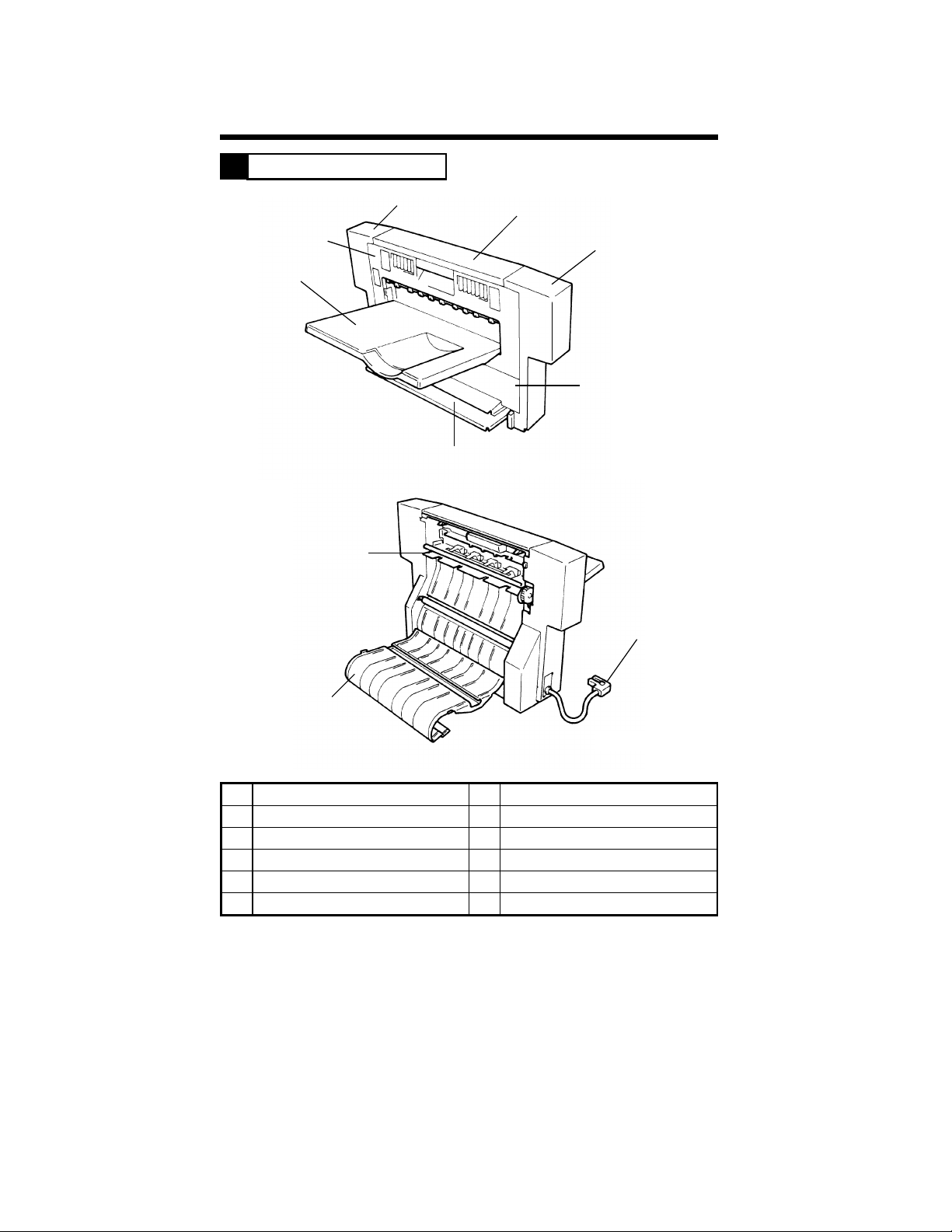
PARTS IDENTIFICATION
2
3
2
1
7
8
4
5
6
4458M001AA
10
9
4458M002AA
No. Name No. Name
1 Exit Tray 6 Exit Section Lower Cover
2 Exit Section Cover 7 Turnover Tray
3 Rear Cover 8 Exit/Turnover Switching Finger
4 Top Cover 9 Vertical Transport Guide
5 Front Cover 10 Hookup Cord
M-2
Page 13
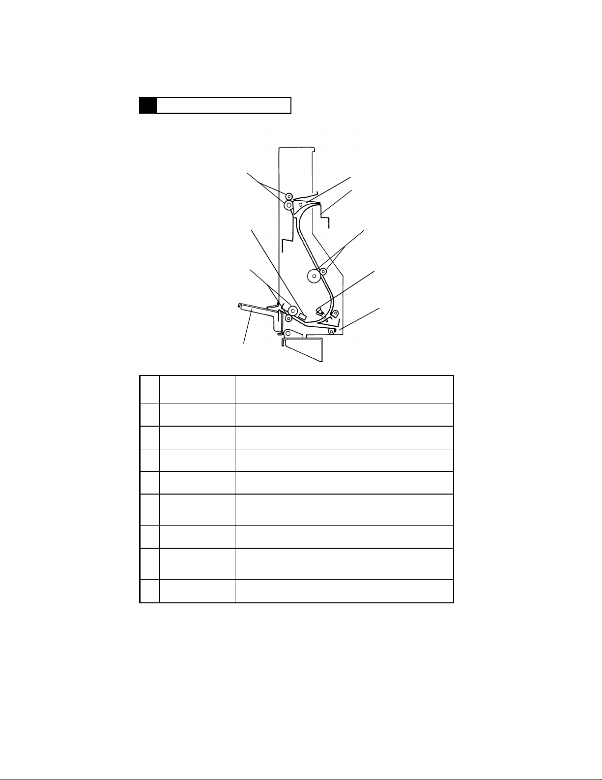
CROSS-SECTIONAL VIEW
3
1
9
8
7
No. Name Function
1 Exit Rollers Feed the copy out onto the Exit Tray.
Exit/Turnover
2
Switching Finger
Vertical Transport
3
Guide
Vertical Transport
4
Rollers
Vertical Transport
5
Sensor PC3
Duplex Paper
6
Take-Up Port
7 Turnover Tray
8 Turnover Rollers
Switchback
9
Sensor PC1
Directs a copy for exit or turnover depending on the
operating mode.
Serves as a guide for the copy for turnover. Used also for
clearing a misfeed.
Transports the copy for turnover. Also removes the fuser
oil from the copy.
Detects a copy to be later turned over. Serves also as a
misfeed sensor.
The port through which the copy which has been turned
over is taken up and fed into the copier for the second
copy cycle.
Prevents the portion of the copy out of the Duplex Unit for
turnover from drooping down.
Reverse the copy fed from the vertical transport section
(switchback motion) so that it can be taken up and fed
again into the copier.
Detects the reference timing for the switchback motion of
the copy fed from the vertical transport section.
2
3
4
5
6
4458M003AA
M-3
Page 14
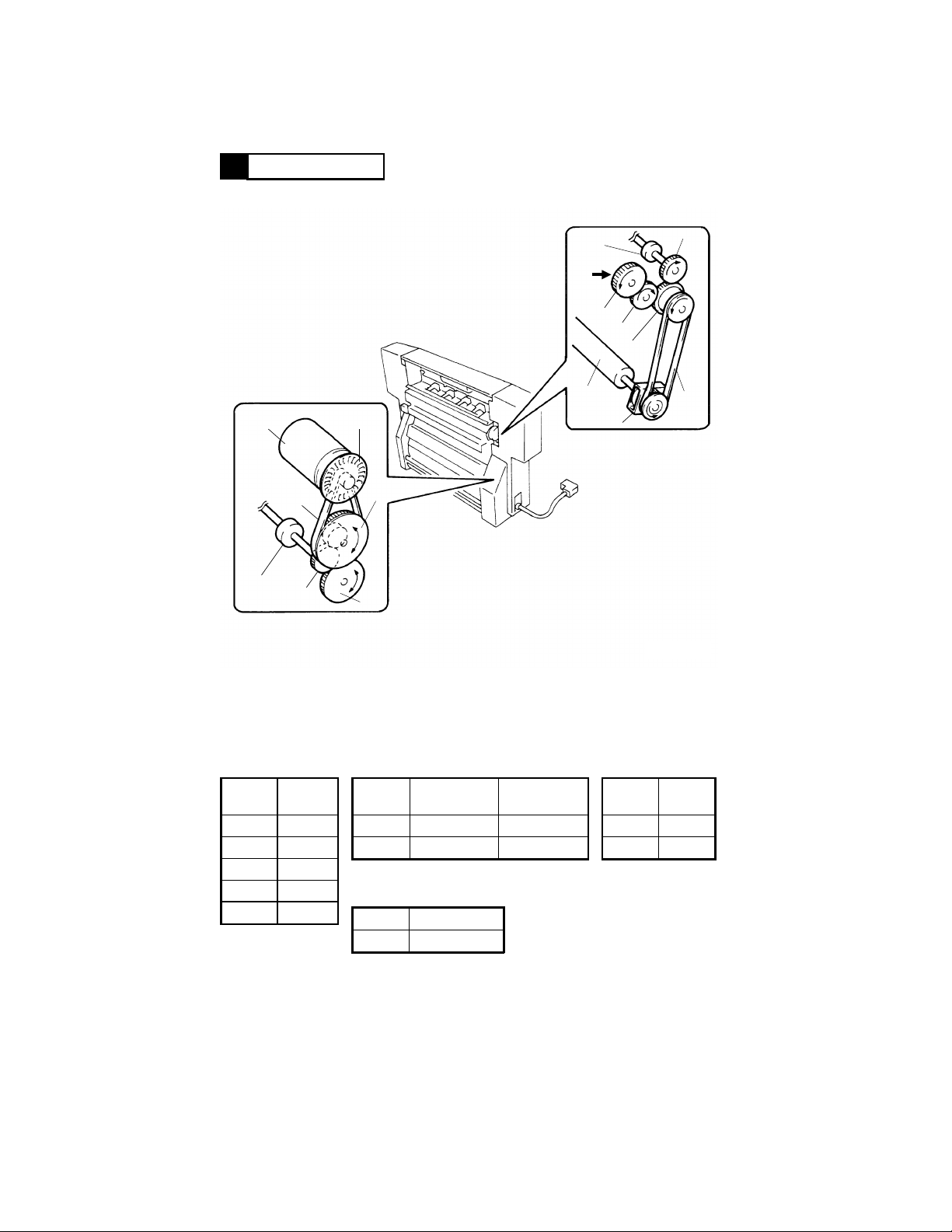
DRIVE SYSTEM
4
M1
Turnover
Roller
B2
G4
P1
PG2
G5
Exit Roller
Drive from
Copier
G1
Vertical
Transport
Roller
G3
G2
PG1
B1
CL1
4458M004AA
Gear
Symbol
G1 30
G2 24
G3 24
G4 19
G5 33
No. of
Teeth
Pulley
Symbol
PG1 31 28
PG2 15 64
No. of
Teeth, Gear
Teeth, Pulley
Pulley
Symbol No. of Teeth
P1 16
M-4
No. of
Belt
Symbol
B1 288
B2 191.01
Length
(mm)
Page 15
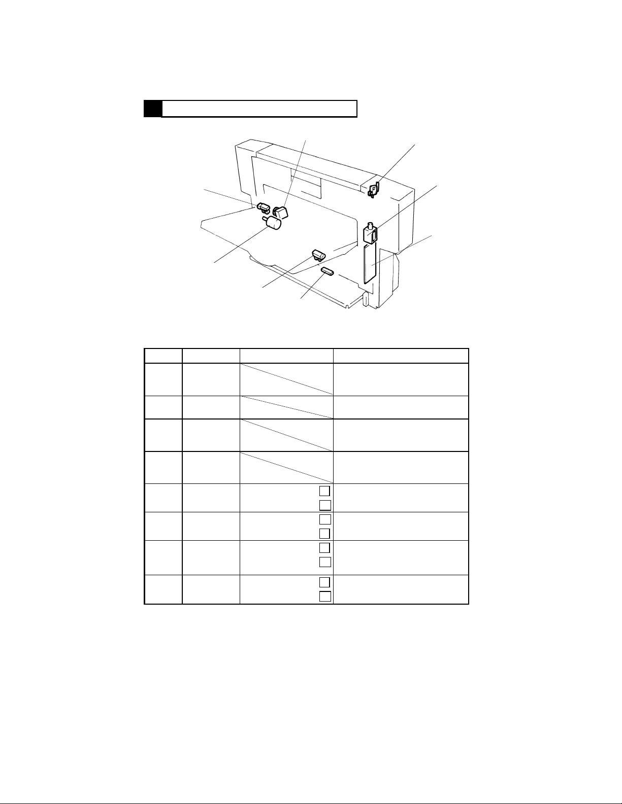
ELECTRICAL COMPONENTS LAYOUT
5
CL1
PC2
M1
PC3
PC1
◆ Function of Each Component
Symbol Name Input Signals (∗) Function
PWB-A Drive Board
M1
SL1
CL1
PC1
(PJ2A-8)
PC2
(PJ3A-2)
PC3
(PJ2A-9)
S1
(PJ2A-6)
Turnover
Motor
Exit/Turnover
Switching
Solenoid
Vertical
Transport
Clutch
Switchback
Sensor
Motor Pulse
Sensor
Vertical
Transport
Sensor
Duplex Unit
Set Switch
Paper present:
Paper not present:
Unblocked:
Blocked:
Paper present:
Paper not present:
Unit in position:
Unit out of position:
Performs communication with the
copier and controls the electrical
components of the Duplex Unit.
Drives the Turnover Rollers to
effect a switchback motion.
Moves the Exit/Turnover
Switching Finger to change the
paper path.
Controls the start and stop of the
Vertical Transport Rollers to keep
the copy in the standby state.
L
Detects the reference timing for a
switchback motion.
H
H
Detects the speed of M1.
L
L
Detects the copy present at the
vertical transport section.
H
L
Detects whether or not the
Duplex Unit is installed in position.
H
S1
SL1
PWB-A
4458M005AA
∗ Signals at the print jack on PWB-A.
M-5
Page 16
DESCRIPTION OF EACH MECHANISM AND CONTROL
6
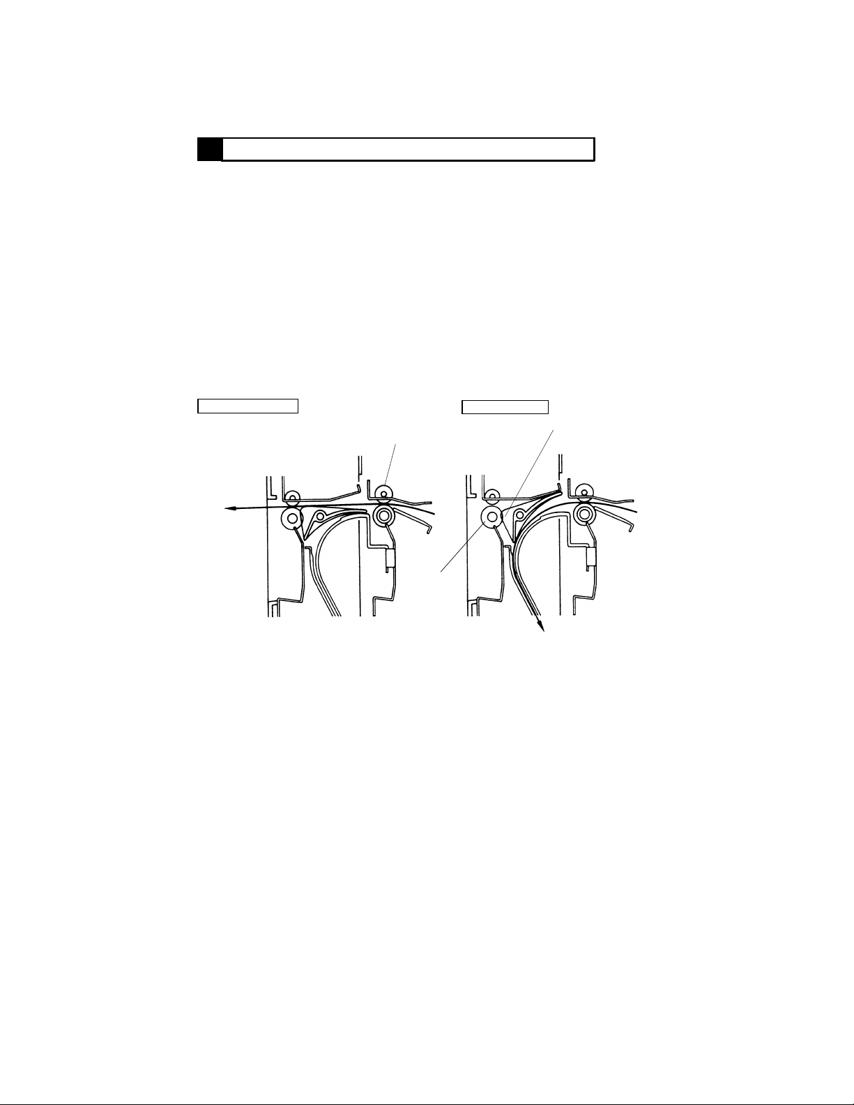
6-1. Exit/Turnover Switching Mechanism
• The exit/turnover switching mechanism uses the Exit/Turnover Switching
Finger that is moved to change the paper path either for exit or turnover.
• When in the Exit mode or when the copy is to be fed out in the Duplex
mode, Exit/Turnover Switching Solenoid SL1 remains deenergized and the
copy moves above the Exit/Turnover Switching Finger and is fed out of the
copier by the Exit Rollers.
• When the copy is to be turned over in the Duplex mode, SL1 is energized
and the copy moves beneath and along the Exit/Turnover Switching Finger
and is fed by the Vertical Transport Rollers of the Duplex Unit down
towards the turnover section.
• As noted above, SL1 moves the Exit/Turnover Switching Finger to change
the paper path. It is energized when a LOW signal from the copier is input
to PJ2A-1 on PWB-A.
SL1: Deenergized
Exit
Paper Exit
Roller of Copier
Exit Roller
SL1: Energized
Exit/Turnover
Switching Finger
To Turnover Section
4458M006AA
M-6
Page 17

6-2. Fuser Oil Cleaning Mechanism
• Since fuser oil is on the front side of the paper after the fusing process, it is
transferred onto the surface of the PC Drum via the Transfer Film during
the second copy process of 2-sided copying, which results in image
problems. Silicone rubber rollers are used as the Vertical Transport
Rollers of the Duplex Unit. They function to recover fuser oil from the
surface of the paper.
6-3. Paper Standby Control
• In a Duplex mode making two or more copy sets of an original set (which
involves two-sheet paper attraction), two sheets of paper are present in the
Duplex Unit, one waiting for take-up from the Duplex Unit following the
turnover cycle and the other remaining stationary at the vertical transport
section. (See "7. OPERATION AND CONTROL" that follows.)
• There is no problem with the paper waiting for take-up from the Duplex Unit
as it is driven independently of the copier drive. The paper at the vertical
transport section is, however, being transported and the drive from the
copier must be cut off. To accomplish this, Vertical Transport Clutch CL1
is mounted on the shaft of the Vertical Transport Roller and it couples or
cuts off the copier drive to the roller.
• CL1 is energized to stop the Vertical Transport Roller rotation when a LOW
signal from the copier is input to PJ2A-4 on PWB-A.
M-7
Page 18
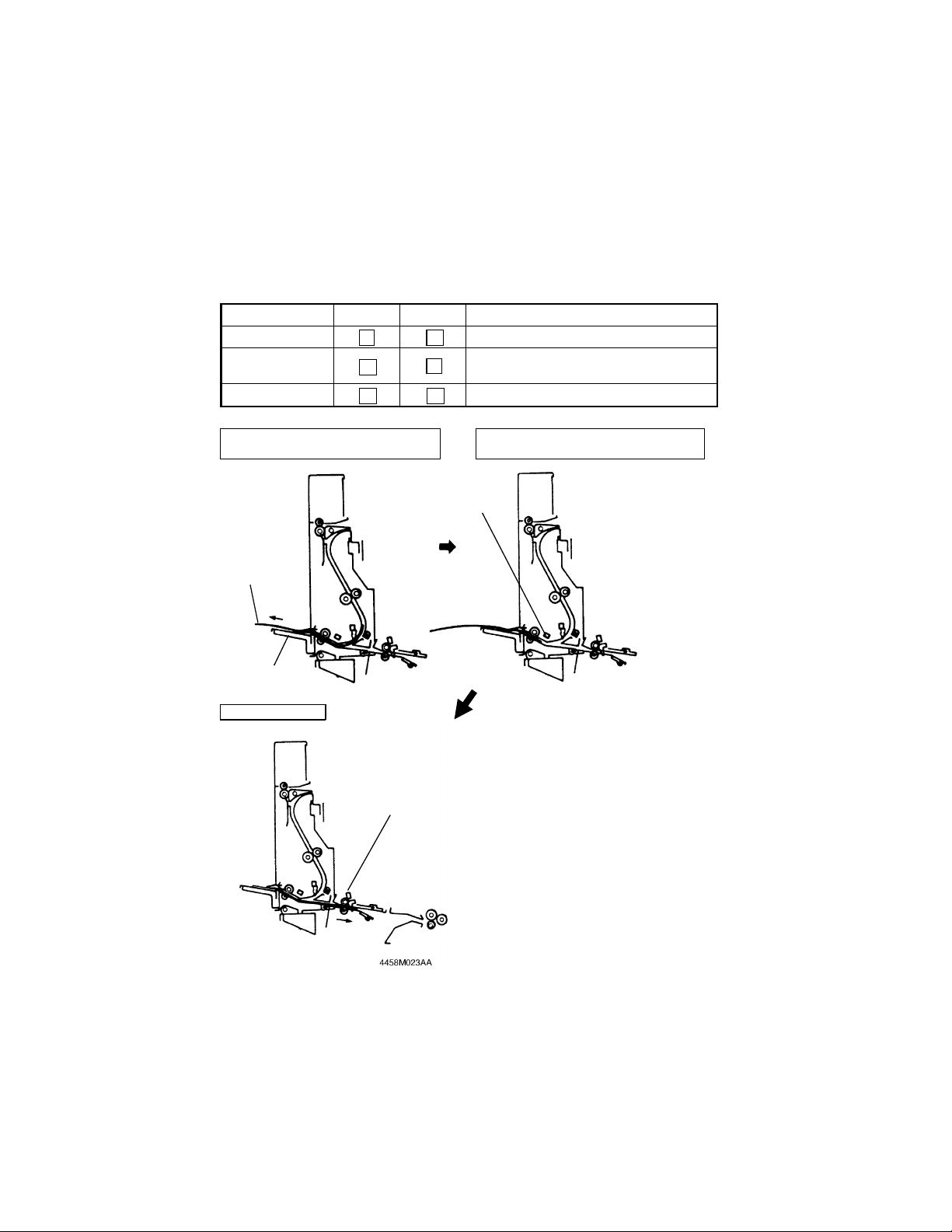
6-4. Switchback Operation (Turnover)
• The Turnover Roller turns forward to transport the copy to the turnover
section and, as soon as the trailing edge of the copy moves past
Switchback Sensor PC1, it stops turning. The Turnover Roller then turns
backward to turn over the copy and feed it back into the copier.
• The drive for the Turnover Roller comes from Turnover Motor M1 which is
turned forward, backward, or stopped by the signals fed from the copier as
follows.
PJ2A-2 PJ2A-3 Copy Motion
Turning forward Transported towards Turnover Tray
Turning backward
Stopped Stationary
L
H
H
H
Transported towards Duplex paper
L
take-up side
H
Copy Transported Towards Turnover
Tray
Copy
Turnover Tray
Standby Position
Horizontal Transport
Sensor of Copier
Turnover Position (Copy is temporarily
stationary)
Switchback
Sensor PC1
4458M007AB
M-8
Page 19

OPERATION AND CONTROL
7
7-1. No. of Multiple 2-Sided Copies
• Copier does not store in memory the image data it scanned. For these
reasons, the number of multiple 2-sided copies that can be made varies
depending on the paper size, copying mode, and whether the Duplexing
Document Feeder is used or not. Here are the details.
Copy Paper Size A5, A4C (∗1) A4L, B4L, A3L
Original Placement ADF Glass ADF Glass
1-sided → 2-sided 99 sets (*2) 2 set 2 set 2 set
2-sided → 2-sided 2 set
Book → 2-sided
Copying Mo de
*L: Lengthwise; C: Crosswise; ADF: Duplexing Document Feeder
*1: Only when two sheets of paper can be placed on Original Glass. For the
other size paper, the same control is provided as that for the paper size of A4L
or larger.
*2: The originals are fed by the 2-in-1 mode and a book copy cycle is repeated in
which two 2-sided copies are made.
*3: A cycle is repeated in which two 2-sided copies are made.
99 sets (*3)
2 set
7-2. Sensor Locations
• The illustration below locates different sensors that provide reference for
paper movement throughout the Duplex Unit.
PC3
PC1
Duplex Unit Side
• PC1: Switchback Sensor
• PC3: Vertical Transport
Sensor
S10
PC24
Copier Side
• PC18: Paper Leading Edge Detecting Sensor
• PC19: Transport Roller Sensor
• PC21: Separating Failure Detecting Sensor
• PC24: Horizontal Transport Sensor
• S10: Paper Exit Switch
PC18
PC21
PC19
Transfer Drum
4458M009AA
M-9
PC Drum
Page 20

7-3. 2-Sided Copying Operation
1) Making 2-Sided Copies from 2-Sided Original Using ADF (One A4C
original, one copy set)
Paper Position Operation Sequence
The copy is separated from the Transfer Drum after
the image transfer process.
Separating Failure Detecting Sensor PC21 is
activated.
The copy reaches Paper Exit Switch S10.
4458M101AA
Exit/Turnover Switching Solenoid SL1 is energized.
The copy is transported to the vertical transport
section to reach Vertical Transport Sensor PC3.
Turnover Motor M1 turns forward.
4458M010AA
4458M011AA
4458M012AA
4458M013AA
The copy reaches Switchback Sensor PC1.
Turnover Motor M1 turns forward to transport the
copy onto the Turnover Tray.
The trailing edge of the copy moves past PC1.
M1 is temporarily deenergized and then starts turning
backward. (The copy is turned over, and then taken
up and fed into the copier.)
The copy reaches Horizontal Transport Sensor PC24.
As Horizontal Transport Drive Clutch CL23 is
energized, the copy is fed onto the Synchronizing
Rollers.
The image transfer to the second face of the copy is
completed and then the copy undergoes separation
and fusing before being fed out of the copier.
4458M014AA
M-10
Page 21

2) Making 2-Sided Copies from 1-Sided Original Using ADF (Two A4C
originals, two copy sets)
Paper Position Operation Sequence
Two sheets of paper for the first original are
separated from the Transfer Drum after the image
transfer process.
The first copy activates Separating Failure Detecting
Sensor PC21.
4458M015AA
4458M016AA
4458M017AA
4458M018AA
The first copy reaches Paper Exit Switch S10.
Exit/Turnover Switching Solenoid SL1 is energized.
The first copy is transported to the vertical transport
section to reach Vertical Transport Sensor PC3.
Turnover Motor M1 turns forward.
The first copy reaches Switchback Sensor PC1.
Turn over Motor M1 turns forward to transport the
first copy onto the Turnover Tray.
As Vertical Transport Clutch CL1 is energized, the
second copy is stationary at the vertical transport
section.
The trailing edge of the first copy moves past PC1.
M1 is temporarily deenergized and then starts turning
backward. (The first copy is turned over, and then
take up and fed into the copier.)
The first copy reaches Horizontal Transport Sensor
PC24.
As Horizontal Transport Drive Clutch CL23 is
energized, the first copy is fed onto the
Synchronizing Rollers.
The first copy reaches Paper Leading Edge Detecting
Sensor PC18 and stops at the Synchronizing Rollers.
➀
4458M019AA
➁
M-11
Page 22

Paper Position Operation Sequence
➀
➁
As CL1 is deenergized and M17 is energized, the
second copy is transported to the turnover section.
The second copy reaches PC1.
M1 turns forward to transport the second copy to the
4458M020AA
Turnover Tray.
The trailing edge of the second copy moves past PC1.
M1 is temporarily deenergized and then starts turning
backward. (The second copy is turned over, and
then take up and fed into the copier.) At the same
time, the first copy is again attracted to the Transfer
Drum.
4458M021AA
The first and second copies are attracted to the
Transfer Drum. When the image transfer to the
second faces of the copies is completed, the copies
undergo separation and fusing before being fed out
of the copier.
4458M015AA
4458M022AA
M-12
Page 23

DIS/REASSEMBLY,
ADJUSTMENT
Precautions for Disassembly, Reassembly and Adjustment
CAUTION
1. Before attempting to disassemble the unit, always make sure that no power is
being supplied from the copier.
2. While power is being supplied to the unit, do not attempt to remove/install the
print jacks from/to the PWBs or unplug/plug in the connectors.
3. If the unit is run with its covers removed, use care not to allow your clothing to
be caught in revolving parts such as the timing belt.
4. The basic rule is do not run the unit any time during dis/reassembly.
Important
1. A toothed washer is used with the screw that secures the ground wire to
ensure positive conduction. Do not forget to insert this washer at reassembly.
2. To reassemble the unit, reverse the order of disassembly unless otherwise
specified.
3. Do not attempt to loosen or remove the screw to which red paint has been
applied.
4. The screw to which blue paint has been applied may be removed, but needs to
be adjusted whenever it has been removed.
Purpose of Applying Red Paint
Red paint is applied to those screws that cannot be readjusted or reinstalled in
the field.
Page 24

Page 25

DISASSEMBLY
1
1-1. Removal of the Exterior Covers and Guides
1
6
4
4458M008AA
3
No. Cover/Guide Name No. of Screws Steps Required Before Removal
1 Rear Cover 4 None
2 Front Cover 4 None
3 Exit Section Lower Cover 4 Removal of the Front and Rear Covers
4 Exit Section Cover 2 Removal of two ornamental covers
5 Turnover Lower Guide 2 Removal of the Front and Rear Covers
6 Vertical Transport Guide 2 Removal of the Front and Rear Covers
5
4458M008AA
2
D-1
Page 26

1-2. Removal of Vertical Transport Clutch CL1
1. Remove the Front and Rear Covers.
2. Remove the Exit Section Lower Cover.
3. Unplug the connector of CL1.
4458D001AA
4. Loosen the screw shown to release the belt tension.
*
Do not forget to tighten this screw at reinstallation.
4458D005AA
5. Snap off one plastic ring and remove the flange and
belt.
4458D002AA
Frame
Collar
0
4458D003AA
CL1
4458D004AA
6. Loosen one screw with an Allen wrench to remove
CL1 and the collar.
*
When reinstalling CL1, press it against the collar and,
at the same time, tighten the screw.
Hook the lock of the clutch onto the frame.
D-2
Page 27

1-3. Removal of the Vertical Transport Roller (Metallic One)
1. Remove the Front and Rear Covers.
2. Unhook two tension coil springs.
4458D006AA
3. Remove the plastic rings and bushings from the front
and rear ends and then remove the Vertical Transport
Roller.
4458D007AA
1-4. Removal of the Vertical Transport Roller (Rubber One)
1. Remove the Front and Rear Covers.
2. Remove the Exit Section Lower Cover.
3. Remove Vertical Transport Clutch CL1 and collar.
4. Remove the plastic ring and bearing from the rear end.
4458D008AA
4458D009AA
5. Remove the plastic rings and bushings from the front
end.
6. Remove the Vertical Transport Roller.
D-3
Page 28

1-5. Removal of the Turnover Entrance Guide
1. Remove the Front and Rear Covers.
2. Remove the Turnover Lower Guide.
3. Remove four screws at the front and rear and the
Turnover Entrance Guide.
4458D014AA
*
Try to press the Turnover Entrance Guide up as
shown at reinstallation.
0
ADJUSTMENTS
2
Vertical
Transport
Frame
Turnover Entrance
Guide
4458D015AA
2-1. Adjustment of Dup. Left-Margin
Requirements: The distance between the front edge of the paper and the front edge of the test
pattern should be 3 ±1.5mm.
4458D018AA
4458D017AA
1. Set the copier into the Service mode and select the
following functions in that order:
"Machine Adjust," "PRT Area," and "Dup. Left-Margin."
2. Select the drawer to be adjusted and press the Start
key.
3. Measure dimension "A" on the test print fed out of the
copier.
*: No adjustments are necessary if the measurement
is 3 ±1.5mm.
4. If the measurement taken in step 3 falls outside the
specified range, adjust using the ▲ or ▼ key.
D-4
Page 29

2-2. Adjustment of Exit/Turnover Switching Solenoid SL1
1. Remove the Front Cover.
2. Remove the harness of Duplex Unit Set Switch S1
from the edge cover.
SL1
3. Unplug the connector from Drive Board PWB-A.
SL1
PWB-A
4458D010AA
4458D011AA
4458D012AA
Upper Guide Plate
Exit/
Turnover
Switching
Finger
4. Remove one screw and the solenoid assy.
5. Unhook the tension coil spring.
6. Remove two screws and the solenoid.
*
When securing the solenoid at reinstallation, slide it
downward as far as it will go.
*
When securing the solenoid assy, ensure that the
Exit/Turnover Switching Finger is in contact with the
sponge of the Upper Guide Plate with the solenoid in
the energized position.
7. After reinstallation, check that the switching finger
operates smoothly.
4458D013AA
D-5
Page 30

D-6
Page 31

TROUBLESHOOTING
General Precautions
CAUTION
1. When servicing the unit with its covers removed, use utmost care to prevent
your hands, clothing, and tools from being caught in revolving parts.
2. Before attempting to replace parts and unplugging connectors, make sure that
no power is being supplied from the copier.
Important
1. Never create a closed circuit across connector pins except those authorized in
the text and on the PWB.
2. When creating a closed circuit and measuring a voltage across connector pins
specified in the text, be sure to use the green wire (GND).
3. Keep all disassembled parts in good order and keep tools under control so that
none will be lost or damaged.
Reading the Text
1. If a component on a PWB or any other functional part including a motor is
defective, the text only instructs you to replace the whole PWB or functional
part and does not give troubleshooting procedure applicable within the
defective part.
2. The text assumes that there are no breaks in the harnesses and cords and all
connectors are plugged into the right positions.
Page 32

Page 33

MISFEED DETECTION
1
1-1. Misfeed Detection Conditions
• A misfeed in the Duplex Unit is detected under any of the following conditions and a misfeed
indication is given on the control panel of the copier. A misfeed can be reset by unlocking and
locking the Duplex Unit.
• A misfeed at the vertical transport section
Type Detection Timing
Paper left Vertical Transport Sensor PC3 is unblocked ( L ) when the Power
Leading edge of paper PC3 is not unblocked ( L ) even after the lapse of approx. 3.3 sec. after
Trailing edge of paper PC3 is not blocked ( H ) even after the lapse of approx. 3.3 sec. after
• A misfeed at the turnover section
Type Detection Timing
Paper left Switchback Sensor PC1 is activated ( L ) when the Power Switch is
Leading edge of paper PC1 is not activated ( H ) even after the lapse of approx. 1.2 sec. after
Trailing edge of paper PC1 is activated ( L ) even after the lapse of approx. 4.8 sec. after PC1
Paper which has been
turned over
Switch is turned ON, a misfeed is reset, or the Front Door is opened and
closed.
Paper Exit Switch S10 of the copier has detected the leading edge of the
paper.
S10 of the copier has detected the trailing edge of the paper.
turned ON, a misfeed is reset, or the Front Door is opened and closed.
PC3 has detected the leading edge of the paper.
has detected the leading edge of the paper.
PC1 detects no paper at a timing when it should have detected paper
after it has been turned over (e.g., when the paper which has been turned
over is pulled out).
• A misfeed at the Duplex paper take-up section
Type Detection Timing
Paper left Horizontal Transport Sensor PC24 of the copier is blocked ( L ) when
Leading edge of paper PC24 of the copier is not blocked ( L ) even after the lapse of approx.
Trailing edge of paper PC24 is not unblocked ( H ) even after the lapse of approx. 1.8 sec.
the Power Switch is turned ON, a misfeed is reset, or the Front Door is
opened and closed.
1.8 sec. after PC1 has detected the leading edge of the paper which was
turned over.
after PC1 has detected the trailing edge of the paper which was turned
over.
T-1
Page 34

1-2. Misfeed Troubleshooting Procedures
• A Misfeed at the Vertical Transport Section
Symptom
A misfeed
occurs
immediately
after the
Power Switch
has been
turned ON.
A misfeed
occurs before
paper
reaches the
vertical
transport
section.
A misfeed
occurs before
paper
reaches PC3.
Step
No.
1 Is Vertical Transport Sensor
PC3 unblocked by a sheet of
paper present at the vertical
transport section of the Duplex
Unit?
2 Does the actuator of PC3
operate properly?
3 Is the voltage across PJ2A-9 on
PWB-A and GND DC5V? Does
that voltage change to DC0V
when PC3 is unblocked?
1 Is Exit/Turnover Switching
Solenoid SL1 energized during
the Duplex mode?
2 Does the voltage across PJ2A-1
on PWB-A and GND change
from DC5V to DC0V when SL1
is energized?
3 Has the Exit/Turnover Switching
Finger been adjusted properly?
1 Do the Vertical Transport Rollers
turn when drive is transmitted
from the copier?
2 Is the voltage across PJ2A-4 on
PWB-A and GND DC5V
normally?
3 Are the Vertical Transport
Rollers dirty or scratched?
Check Item Result Action
YES Remove the paper from the
vertical transport section.
NO Check the installed position of
PC3 and check the actuator for
deformation and foreign matter.
YES Make checks on the copier side.
NO Check the wiring between
PWB-A and PC3 and, if it is
intact, replace PC3 or PWB-A.
YES Go to step 3.
YES Check the wiring between
PWB-A and SL1 and, if it is
intact, replace SL1 or PWB-A.
NO Make checks on the copier side.
YES Clean the Exit/Turnover
Switching Finger and guide plate.
NO Adjust SL1.
YES Go to step 3.
YES Check the wiring between
PWB-A and Vertical Transport
Clutch CL1 and, if it is intact,
replace CL1 or PWB-A.
NO Make checks on the copier side.
YES Clean or replace the defective
Vertical Transport Roller.
NO Clean the Vertical Transport
Guide and check it for
deformation.
T-2
Page 35

• A Misfeed at the Vertical Transport Section
Symptom
A misfeed
occurs after
paper has
reached
Vertical
Transport
Sensor PC3.
Step
No.
1 Does Turnover Motor M1 turn
when paper is fed into the
Duplex Unit?
2 Does the voltage across PJ2A-2
on PWB-A and GND change
from DC5V to DC0V when M1 is
energized?
3 Does the actuator of PC3
operate properly?
4 Is the voltage across PJ2A-9 on
PWB-A and GND DC5V? Does
that voltage change to DC0V
when PC3 is unblocked?
Check Item Result Action
YES Go to step 3.
YES Check the wiring between
PWB-A and M1 and, if it is
intact, replace M1 or PWB-A.
NO Make checks on the copier side.
NO Check the installed position of
PC3 and check the actuator for
deformation and foreign matter.
YES Make checks on the copier side.
NO Check the wiring between
PWB-A and PC3 and, if it is
intact, replace PC3 or PWB-A.
T-3
Page 36

• A Misfeed at the Turnover Section
Symptom
A misfeed
occurs
immediately
after the
Power Switch
has been
turned ON.
Paper is yet
to reach PC1.
Paper is
stationary at
the Turnover
Rollers.
Paper is not
transported to
the Duplex
paper take-up
side.
Step
No.
1 Is Switchback Sensor PC1
activated by a sheet of paper
present at the turnover section
of the Duplex Unit (or dust on
the underside of the sensor)?
2 Is PC1 installed correctly? NO Correct the installed position of
3 Is the voltage across PJ2A-8 on
PWB-A and GND DC5V? Does
that voltage change to DC0V
when a sheet of paper is
inserted to activate PC1?
1 Is the Turnover Entrance Guide
deformed or dirty?
1 Does Turnover Motor M1 turn
when paper is fed into the
Duplex Unit?
2 Does the voltage across PJ2A-2
on PWB-A and GND change
from DC5V to DC0V when M1 is
energized?
1 Does M1 turn backward after
paper has been fed out onto the
Turnover Tray?
2 Does the voltage across PJ2A-3
on PWB-A and GND change
from DC5V to DC0V when M1 is
energized?
Check Item Result Action
YES Remove the paper from the
turnover section. Or clean the
underside of the sensor.
PC1.
YES Make checks on the copier side.
NO Check the wiring between
PWB-A and PC1 and, if it is
intact, replace PC1 or PWB-A.
YES Clean or replace the Turnover
Entrance Guide.
NO Check the Vertical Transport
Guide and Vertical Transport
Rollers for dirt and deformation.
YES Clean the Turnover Rollers and
Turnover Guide.
YES Check the wiring between
PWB-A and M1 and, if it is
intact, replace M1 or PWB-A.
NO Make checks on the copier side.
YES Clean the Turnover Rollers and
Turnover Guide.
YES Check the wiring between
PWB-A and M1 and, if it is
intact, replace M1 or PWB-A.
NO Make checks on the copier side.
T-4
Page 37

• A Misfeed at the Duplex Paper Take-Up Section
Symptom
A misfeed
occurs
immediately
after the
Power Switch
has been
turned ON.
A misfeed
occurs before
paper
reaches
Horizontal
Transport
Sensor PC24.
A misfeed
occurs after
paper has
reached
PC24 of the
copier.
Step
No.
1 See TROUBLESHOOTING of
the copier.
1 Is the Turnover Entrance Guide
or Turnover Lower Guide
deformed or dirty?
2 Is the Turnover Roller or the
Duplex Paper Take-Up Guide of
the copier deformed or dirty?
1 See TROUBLESHOOTING of
the copier.
Check Item Result Action
YES Clean or replace the Turnover
Entrance Guide or Turnover
Lower Guide.
YES Clean or replace the Turnover
Roller or the Duplex Paper
Take-Up Guide of the copier.
NO Check Horizontal Transport
Drive Clutch CL23 of the copier.
T-5
Page 38

T-6
Page 39

WIRING DIAGRAMS
Page 40

Page 41

WIRING DIAGRAMS
NOT AVAILABLE IN
PDF FORMAT
Page 42

Page 43

PARTS CATALOG
Model
AD-723
FEBRUARY 1999
KONICA BUSINESS TECHNOLOGIES, INC.
Page 44

Page 45

How to use this catalog
This parts catalog includes illustrations and part numbers for all replacement parts and assemblies used in this model.
Model-specific parts are identified in the illustrations with reference
numbers. Use the reference number to locate the corresponding part
number on the facing page.
Common hardware items, such as screws, nuts, washers, and pins,
are identified in the illustrations with reference letters. Use the reference
letter to locate the corresponding part number on the hardware listing in
the lower right hand corner of the facing page.
If you know a part number, but don’t know where the part is used, use
the numerical index to determine the page number and reference number for that part. Because some common parts are used in several
places, there may be more than one entry. Refer to the illustrations to
see where the part may be used.
If you know a part’s description, but don’t know where to look to find
the part number, use the alphabetical index to determine likely page and
reference numbers. Then look at the illustrations to determine that you
have identified the correct part. Locate the part number using the listing
on the opposite page.
Retail pricing that appears with the numerical index, while valid when
this catalog was printed, is subject to change without notice. The prices
are only suggested prices and are provided only for reference. Dealers
may determine their own selling prices. For up-to-date pricing, refer to
current Konica price lists or contact the Konica Parts Distribution Center.
How to order parts
Use standard Konica parts ordering procedures to obtain these parts.
For ordering options, contact Konica’s Parts Distribution Center.
When ordering parts, be sure to specify part numbers exactly as listed in
this catalog.
NOTE: Electrical parts may include previously used components.
Model AD-723 Konica Business Technologies, Inc. Page iii
1st Edition February, 1999
Page 46

This page left blank intentionally.
Page iv Konica Business Technologies, Inc. Model AD-723
February, 1999 1st Edition
Page 47

How to use this catalog . . . . . . . . . . . . . . . . . . . . . . . . . iii
Contents . . . . . . . . . . . . . . . . . . . . . . . . . . . . . 1
Machine parts
Housing . . . . . . . . . . . . . . . . . . . . . . . . . . . . . 2
Driving Section . . . . . . . . . . . . . . . . . . . . . . . . . . 4
Alphabetical index . . . . . . . . . . . . . . . . . . . . . . . . . . . . 9
Numerical index, Retail price list . . . . . . . . . . . . . . . . . . . . 11
Contents
Model AD-723 Konica Business Technologies, Inc. Page 1
1st Edition February, 1999
Page 48

Housing
Page 2 Konica Business Technologies., Inc. Model AD-723
February, 1999 1st Edition
Page 49

REF. PART NUMBER DESCRIPTION
NO.
1 12ZN97010 Label (Caution Hot)
2 12ZN44010 Rear cover
3 12ZN44020 Cord bushing
4 12ZN44030 Bracket
5 25TU05120 Edge cover
6 12ZN44050 Bracket
7 12ZN44060 Torsion spring
8 12ZN44070 Lock lever
9 12ZN44080 Bracket
10 12ZN97020 Label (Look Release)
11 12ZN44090 Cover
12 25TU12060 Cover
13 12ZN44110 Cover
14 12ZN44120 Bracket
15 12ZN44130 Guide plate
16 12ZN44140 Shoulder screw
17 12ZN44150 Cover
18 12ZN97030 Label (Jam Removal)
19 12ZN44160 Front frame
20 12ZN44170 Shaft
21 12ZN44180 Cushion
22 12ZN44190 Lock plate
23 12ZN44200 Lock release lever
24 12ZN44210 Top cover
25 12ZN97040 Label
26 12ZN44220 Plate spring
27 25TU40140 Roll
28 12ZN44240 Seal
29 12ZN44250 Guide plate
30 12ZN44260 Sponge
31 12ZN44270 Support plate
32 12ZN44280 Shaft
33 25TU40150 Plate spring
34 12ZN44300 Label (Caution Hot)
35 12ZN44310 Turnover tray
36 12ZN44760 Cover
HARDWARE
REF.
LTR.
a 25TU01440
b 25TU01530
c 25TU01590
d 25TU02410
e 25TU02460
f 25TU02850
g 25TU03420
h 25TU03630
i 25TU03710
j 25TU03730
PART
NUMBER
Model AD-723 Konica Business Technologies., Inc. Page 3
1st Edition February, 1999
Page 50

Driving Section
Page 4 Konica Business Technologies., Inc. Model AD-723
February, 1999 1st Edition
Page 51

REF. PART NUMBER DESCRIPTION
NO.
1 12ZN77010 Gear (Z=30)
2 12ZN77020 Gear (Z=24)
3 12ZN44320 Flange
4 12ZN78010 Timing belt
5 12ZN44330 Pulley (Z=31)
6 12ZN44080 Bracket
7 12ZN44350 Pulley (Z=16)
8 12ZN78020 Timing belt
9 25TU85010 Photosensor
10 12ZN44360 Bracket
11 12ZN80010 Motor
12 12ZN77030 Gear (Z=33)
13 12ZN77040 Pulley gear (Z=64,15)
14 12ZN77050 Gear (Z=19)
15 12ZN44370 Tension spring
16 25TU75470 Bushing
17 12ZN44380 Roll
18 12ZN44390 Bracket
19 12ZN44400 Tension spring
20 12ZN75020 Bushing
21 25TU78010 Gear (Z=24)
22 12ZN44410 Bracket
23 12ZN44420 Tension spring
24 12ZN82010 Clutch
25 12ZN44430 Washer
26 25TU75660 Ball bearing
27 12ZN44440 Guide plate
28 25TU40300 Sponge
29 25TU40330 Holder
30 12ZN90010 Harness
31 12ZN44470 Ferrite core
32 12ZN44480 Retaining ring
33 25TU53120 Shaft
34 25TU40320 Actuator
35 25TU40290 Torsion spring
36 25TU85140 Photosensor
37 12ZN44520 Guide plate
38 12ZN44530 Guide plate
39 12ZN90020 Harness
40 25TU20290 PWB support
41 12ZN-9010 PW board (A)
42 25TU60860 PWB support
43 12ZN44560 Bracket
44 12ZN82020 Solenoid
45 12ZN44570 Guide plate
46 12ZN44580 Guide plate
47 12ZN44590 Neutralizing brush
48 25TU10150 Bracket
49 25TU85070 Microswitch
50 12ZN44610 Torsion spring
HARDWARE
REF.
LTR.
a 25TU01170
b 25TU01400
c 25TU01630
d 25TU01520
e 25TU02140
f 25TU04010
g 25TU02410
h 25TU02430
i 25TU02450
j 25TU02460
k 25TU03210
m 25TU03710
n 25TU03720
PART
NUMBER
Model AD-723 Konica Business Technologies., Inc. Page 5
1st Edition February, 1999
Page 52

Driving Section
Page 6 Konica Business Technologies., Inc. Model AD-723
February, 1999 1st Edition
Page 53

REF. PART NUMBER DESCRIPTION
NO.
51 25TU10140 Shoulder screw
52 12ZN75040 Bushing
53 25TU75420 Bushing
54 12ZN75060 Bushing
55 12ZN44140 Shoulder screw
56 12ZN44640 Tension spring
57 12ZN44650 Lever
58 12ZN97060 Label
59 25TU40260 Knob
60 12ZN44670 Cushion
61 12ZN44680 Sponge
62 12ZN44690 Guide plate
63 12ZN44700 Guide lever
64 12ZN44710 Neutralizing brush
65 12ZN44720 Roller
66 12ZN44730 Roller
67 12ZN44740 Roller
68 12ZN44750 Roller
69 12ZN83010 Fuse
HARDWARE
REF.
LTR.
a 25TU01170
b 25TU01400
c 25TU01630
d 25TU01520
e 25TU02140
f 25TU04010
g 25TU02410
h 25TU02430
i 25TU02450
j 25TU02460
k 25TU03210
m 25TU03710
n 25TU03720
PART
NUMBER
Model AD-723 Konica Business Technologies., Inc. Page 7
1st Edition February, 1999
Page 54

This page left blank intentionally.
Page 8 Konica Business Technologies, Inc. Model AD-723
February, 1999 1st Edition
Page 55

Alphabetical index
PART PAGE REF.
DESCRIPTION NO. NO.
A
Actuator . . . . . . . . . . 5 34
B
Ball bearing . . . . . . . . 5 26
Bracket . . . . . . . . . . . 3 4
Bracket . . . . . . . . . . . 3 6
Bracket . . . . . . . . . . . 3 9
Bracket . . . . . . . . . . . 3 14
Bracket . . . . . . . . . . . 5 6
Bracket . . . . . . . . . . . 5 10
Bracket . . . . . . . . . . . 5 18
Bracket . . . . . . . . . . . 5 22
Bracket . . . . . . . . . . . 5 43
Bracket . . . . . . . . . . . 5 48
Bushing . . . . . . . . . . 5 16
Bushing . . . . . . . . . . 5 20
Bushing . . . . . . . . . . 7 52
Bushing . . . . . . . . . . 7 53
Bushing . . . . . . . . . . 7 54
C
Clutch . . . . . . . . . . . 5 24
Cord bushing . . . . . . . . 3 3
Cover . . . . . . . . . . . . 3 11
Cover . . . . . . . . . . . . 3 12
Cover . . . . . . . . . . . . 3 13
Cover . . . . . . . . . . . . 3 17
Cover . . . . . . . . . . . . 3 36
Cushion . . . . . . . . . . 3 21
Cushion . . . . . . . . . . 7 60
E
Edge cover . . . . . . . . . 3 5
F
Ferrite core . . . . . . . . . 5 31
Flange . . . . . . . . . . . 5 3
Front frame . . . . . . . . . 3 19
Fuse . . . . . . . . . . . . 7 69
PART PAGE REF.
DESCRIPTION NO. NO.
Gear (Z=30) . . . . . . . . 5 1
Gear (Z=33) . . . . . . . . 5 12
Guide lever . . . . . . . . . 7 63
Guide plate . . . . . . . . . 3 15
Guide plate . . . . . . . . . 3 29
Guide plate . . . . . . . . . 5 27
Guide plate . . . . . . . . . 5 37
Guide plate . . . . . . . . . 5 38
Guide plate . . . . . . . . . 5 45
Guide plate . . . . . . . . . 5 46
Guide plate . . . . . . . . . 7 62
H
Harness . . . . . . . . . . 5 30
Harness . . . . . . . . . . 5 39
Holder . . . . . . . . . . . 5 29
K
Knob . . . . . . . . . . . . 7 59
L
Label . . . . . . . . . . . . 3 25
Label . . . . . . . . . . . . 7 58
Label (Caution Hot) . . . . 3 1
Label (Caution Hot) . . . . 3 34
Label (Jam Removal) . . . 3 18
Label (Look Release) . . . 3 10
Lever . . . . . . . . . . . . 7 57
Lock lever . . . . . . . . . 3 8
Lock plate . . . . . . . . . 3 22
Lock release lever . . . . . 3 23
M
Microswitch . . . . . . . . . 5 49
Motor . . . . . . . . . . . . 5 11
N
Neutralizing brush . . . . . 5 47
Neutralizing brush . . . . . 7 64
PART PAGE REF.
DESCRIPTION NO. NO.
Photosensor . . . . . . . . 5 9
Photosensor . . . . . . . . 5 36
Plate spring . . . . . . . . . 3 26
Plate spring . . . . . . . . . 3 33
Pulley (Z=16) . . . . . . . . 5 7
Pulley (Z=31) . . . . . . . . 5 5
Pulley gear (Z=64,15) . . . 5 13
R
Rear cover . . . . . . . . . 3 2
Retaining ring . . . . . . . . 5 32
Roll . . . . . . . . . . . . . 3 27
Roll . . . . . . . . . . . . . 5 17
Roller . . . . . . . . . . . . 7 65
Roller . . . . . . . . . . . . 7 66
Roller . . . . . . . . . . . . 7 67
Roller . . . . . . . . . . . . 7 68
S
Seal . . . . . . . . . . . . . 3 28
Shaft . . . . . . . . . . . . 3 20
Shaft . . . . . . . . . . . . 3 32
Shaft . . . . . . . . . . . . 5 33
Shoulder screw . . . . . . . 3 16
Shoulder screw . . . . . . . 7 51
Shoulder screw . . . . . . . 7 55
Solenoid . . . . . . . . . . 5 44
Sponge . . . . . . . . . . . 3 30
Sponge . . . . . . . . . . . 5 28
Sponge . . . . . . . . . . . 7 61
Support plate . . . . . . . . 3 31
T
Tension spring . . . . . . . 5 15
Tension spring . . . . . . . 5 19
Tension spring . . . . . . . 5 23
Tension spring . . . . . . . 7 56
Timing belt . . . . . . . . . 5 4
Timing belt . . . . . . . . . 5 8
Top cover . . . . . . . . . . 3 24
Torsion spring . . . . . . . . 3 7
Torsion spring . . . . . . . . 5 35
Torsion spring . . . . . . . . 5 50
Turnover tray . . . . . . . . 3 35
G
Gear (Z=19) . . . . . . . . 5 14
Gear (Z=24) . . . . . . . . 5 2
Gear (Z=24) . . . . . . . . 5 21
P
PW board (A) . . . . . . . . 5 41
PWB support . . . . . . . . 5 40
PWB support . . . . . . . . 5 42
W
Washer . . . . . . . . . . . 5 25
Model AD-723 Konica Business Technologies, Inc. Page 9
1st Edition February, 1999
Page 56

This page left blank intentionally.
Page 10 Konica Business Technologies, Inc. Model AD-723
February, 1999 1st Edition
Page 57

Numerical index
PART PAGE REF.SUGGESTED
NUMBER NO. NO. RETAIL
12ZN-9010 . . . . 5 41
12ZN44010 . . . 3 2
12ZN44020 . . . 3 3
12ZN44030 . . . 3 4
12ZN44050 . . . 3 6
12ZN44060 . . . 3 7
12ZN44070 . . . 3 8
12ZN44080 . . . 3 9
12ZN44080 . . . 5 6
12ZN44090 . . . 3 11
12ZN44110 . . . . 3 13
12ZN44120 . . . 3 14
12ZN44130 . . . 3 15
12ZN44140 . . . 3 16
12ZN44140 . . . 7 55
12ZN44150 . . . 3 17
12ZN44160 . . . 3 19
12ZN44170 . . . 3 20
12ZN44180 . . . 3 21
12ZN44190 . . . 3 22
12ZN44200 . . . 3 23
12ZN44210 . . . 3 24
12ZN44220 . . . 3 26
12ZN44240 . . . 3 28
12ZN44250 . . . 3 29
12ZN44260 . . . 3 30
12ZN44270 . . . 3 31
12ZN44280 . . . 3 32
12ZN44300 . . . 3 34
12ZN44310 . . . 3 35
12ZN44320 . . . 5 3
12ZN44330 . . . 5 5
12ZN44350 . . . 5 7
12ZN44360 . . . 5 10
12ZN44370 . . . 5 15
12ZN44380 . . . 5 17
PART PAGE REF.SUGGESTED
NUMBER NO. NO. RETAIL
12ZN44390 . . . . 5 18
12ZN44400 . . . . 5 19
12ZN44410 . . . . 5 22
12ZN44420 . . . . 5 23
12ZN44430 . . . . 5 25
12ZN44440 . . . . 5 27
12ZN44470 . . . . 5 31
12ZN44480 . . . . 5 32
12ZN44520 . . . . 5 37
12ZN44530 . . . . 5 38
12ZN44560 . . . . 5 43
12ZN44570 . . . . 5 45
12ZN44580 . . . . 5 46
12ZN44590 . . . . 5 47
12ZN44610 . . . . 5 50
12ZN44640 . . . . 7 56
12ZN44650 . . . . 7 57
12ZN44670 . . . . 7 60
12ZN44680 . . . . 7 61
12ZN44690 . . . . 7 62
12ZN44700 . . . . 7 63
12ZN44710 . . . . 7 64
12ZN44720 . . . . 7 65
12ZN44730 . . . . 7 66
12ZN44740 . . . . 7 67
12ZN44750 . . . . 7 68
12ZN44760 . . . . 3 36
12ZN75020 . . . . 5 20
12ZN75040 . . . . 7 52
12ZN75060 . . . . 7 54
12ZN77010 . . . . 5 1
12ZN77020 . . . . 5 2
12ZN77030 . . . . 5 12
12ZN77040 . . . . 5 13
12ZN77050 . . . . 5 14
12ZN78010 . . . . 5 4
PART PAGE REF.SUGGESTED
NUMBER NO. NO. RETAIL
12ZN78020 . . . . 5 8
12ZN80010 . . . . 5 11
12ZN82010 . . . . 5 24
12ZN82020 . . . . 5 44
12ZN83010 . . . . 7 69
12ZN90010 . . . . 5 30
12ZN90020 . . . . 5 39
12ZN97010 . . . . 3 1
12ZN97020 . . . . 3 10
12ZN97030 . . . . 3 18
12ZN97040 . . . . 3 25
12ZN97060 . . . . 7 58
25TU05120 3 5
25TU10140 . . . . 7 51
25TU10150 . . . . 5 48
25TU12060 . . . . 3 12
25TU20290 . . . . 5 40
25TU40140 . . . . 3 27
25TU40150 . . . . 3 33
25TU40260 . . . . 7 59
25TU40290 . . . . 5 35
25TU40300 . . . . 5 28
25TU40320 . . . . 5 34
25TU40330 . . . . 5 29
25TU53120 . . . . 5 33
25TU60860 . . . . 5 42
25TU75420 . . . . 7 53
25TU75470 . . . . 5 16
25TU75660 . . . . 5 26
25TU78010 . . . . 5 21
25TU85010 . . . . 5 9
25TU85070 . . . . 5 49
25TU85140 . . . . 5 36
25TUO5120 . . . 3 5
Model AD-723 Konica Business Technologies, Inc. Page 11
1st Edition February, 1999
Page 58

This page left blank intentionally.
Page 12 Konica Business Technologies, Inc. Model AD-723
February, 1999 1st Edition
 Loading...