


VI Network
(For administrator)
This volume explains how to make the network settings.
Chapter 17 Summary of Network |
|
Functions ........................... |
446 |
Chapter 18 Setting from the Control |
|
Panel.................................. |
451 |
Chapter 19 Using Utilities...................... |
542 |
Chapter 20 Printing with IP Peer-to-Peer (Windows 95/98/Me only) ... 549
Chapter 21 Using IPX Peer-to-Peer |
|
|
|
(Windows 95/98/Me only) ... 569 |
|
Chapter 22 Settings for Printing with LPD/ |
||
|
LPR (Windows NT 4.0/2000/XP |
|
|
only) ..................................... |
576 |
Chapter 23 |
Using with NetWare ............ |
601 |
Chapter 24 Using via the Internet (Windows |
||
|
2000/XP) ............................... |
608 |
Chapter 25 |
UNIX Configuration............. |
624 |
Chapter 26 |
Use with AppleTalk............. |
637 |
Chapter 27 |
When There Is Trouble on the |
|
|
Network................................ |
643 |
445

VI Network (For administrator)
Chapter 17 Summary of Network Functions
This chapter summarizes the print controller network functions.
17-1. |
Network functions........................................................................... |
447 |
17-2. |
Network function usage ................................................................. |
449 |
17-3. |
Network setting item list................................................................. |
450 |
446

17-1. Network functions
Features of network functions
This unit can handle various network environments flexibly and is equipped with the following network functions.
10Base-T/100Base-TX (Fast Ethernet) automatic selection
It supports for multiple protocols (TCP/IP, IPX/SPX, AppleTalk (EtherTalk))
Through dedicated utilities, it supports IP Peer-to-Peer printing through TCP/IP from Microsoft Windows 95/98/Me.
Through dedicated utilities, it supports IPX Peer-to-Peer printing through IPX/SPX from MicroSoft Windows 95/98/Me.
It supports LPD/LPR on TCP/IP for Microsoft Windows NT 4.0/2000/XP.
It supports lpd/lpr on TCP/IP for UNIX.
It supports Novell NetWare printer server functions and supports both bindary mode and Novell Directory Service (NDS).
It supports AppleTalk on Macintosh.
An HTTP server is built in and through links with the accessory Management Access Program (MAP), standard web browser, etc., the printing system can be managed.
It supports for acquiring IP addresses automatically through DHCP
It supports for setting up Netware on NWSetup utility for Microsoft Windows 95/98/Me/NT 4.0/2000/XP.
It supports for assigning IP addresses on BOOTP Lite utility for Microsoft Windows 95/98/Me/NT 4.0/2000/XP.
It supports printing from various UNIX systems through UNIX-TCP/IP Programs.
Use with peer-to-peer connections (Windows 95/98/Me)
With LAN (Local Area Network) comprised solely of computers running Windows 95/98/Me, the printer can be used even without a dedicated printer server. In this case, the print controller is connected to the network with a connection configuration called peer-to-peer.
zPeer-to-peer: A network configuration that connects computers under equivalent conditions without using a central server.
447 |
VI Network (For administrator) |
|
Chapter 17 Summary of Network Functions |

17-1. Network functions
Use through LPD/LPR (Windows NT 4.0/2000/XP)
This printing system supports printing with LPD/LPR with Windows NT 4.0/2000/XP.
You can connect the print controller to a print server in a UNIX environment and send print instructions to the printer from Windows NT 4.0/2000/XP.
zThis must be a print request format that can be used with LPD (Line Printer Deamon)/LPR:Windows NT 4.0/2000/XP.
Using with UNIX
This printing system supports printing with lpd/lpr with UNIX.
You can connect the print controller to a print server in a UNIX environment and sent print instructions to the printer from various UNIX systems.
Using with NetWare
The Novell NetWare 3.x or Novell NetWare 4.x printer server functions are supported.
You can connect the print controller to a network that uses Novell NetWare 3.x or 4.x as the network OS and send print instructions to the printer server (network controller) from a client terminal.
zFor details on NetWare functions, refer to the NetWare manual.
Using with Macintosh (Only when PostScript option installed)
Printing on a Macintosh with AppleTalk is supported.
You can connect the print controller to the AppleTalk environment print server and send print instructions to the printer from a Macintosh.
448 |
VI Network (For administrator) |
|
Chapter 17 Summary of Network Functions |
17-2. Network function usage
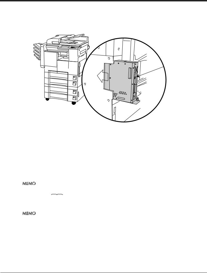
Connection with the network
Please connect the UTP cable (Category 5 recommended) connected to the network to the Ethernet connector (RJ-45) of the print controller (network controller).
The settings required for connecting to the network depend on the environment of the network the print controller is connected to, the OS of the computers making up the network, etc. Make the settings required to match the environment into which this system is being introduced.
Network setting method
There are the following two methods for making the print controller network settings.
Setting from the copier control panel
Load the setting screen from the copier’s control panel and set the network functions.
zFor the method setting the network functions from the copier’s control panel, refer to [Chapter 18 Setting from the Control Panel] (


 page Page 451)
Setting using the Web Utilities
This sets the network controller from a computer connected to the network using the Web Utilities.
zFor details on the Web Utilities, refer to the Web Utilities user’s manual.
449 |
VI Network (For administrator) |
|
Chapter 17 Summary of Network Functions |

17-3. Network setting item list
This explains the settings required when connecting the print controller to the network.
Set each setting item to match the environment of the network to which the print controller is connected. When changing the setting for an item, ask the network administrator.
Unit Info (


 Page 457)
Check such information as the MAC address and ROM version for the network controller.
Update NIC (


 Page 458)
The “Network setting” items are updated to the changed contents.
Print on Startup (


 Page 462)
This sets whether or not to output the “Network settings list” immediately after the copier power is switched on.
TCP/IP Setup (


 Page 464)
This sets the items required for communicating with TCP/IP.
NetWare Setup (


 Page 482)
This sets the items required for communicating with NetWare.
AppleTalk Setup (


 Page 501)
This sets the items required for communicating with AppleTalk.
WINS Setup (


 Page 508)
This sets the items required for searching with NetBIOS.
FTP Setup (


 Page 515)
This sets the items for sending scanned images from the print controller to the FTP server.
Email Setup (


 Page 520)
This sets the items required for sending scanned images from the print controller as email attachments.
DNS Setup (


 Page 535)
This sets the items required for using a DNS server in the network to which the print controller is connected.
Admin Password (


 Page 460)
This is used for changing the Network controller password.
Factory Default (


 Page 540)
This returns the “Network settings” to their default state (the factory defaults).
450 |
VI Network (For administrator) |
|
Chapter 17 Summary of Network Functions |

VI Network (For administrator)
Chapter 18 Setting from the Control Panel
This chapter explains the method for making the network settings from the Copier’s control panel.
18-1. Method for setting network from control panel.......................... |
452 |
|
18-2. NIC .................................................................................................. |
457 |
|
18-3. Print on startup.............................................................................. |
462 |
|
18-4. TCP/IP setup .................................................................................. |
464 |
|
18-5. NetWare setup ............................................................................... |
482 |
|
18-6. |
AppleTalk setup............................................................................. |
501 |
18-7. |
WINS setup .................................................................................... |
508 |
18-8. |
FTP setup ....................................................................................... |
515 |
18-9. |
Email setup .................................................................................... |
520 |
18-10. DNS setup ...................................................................................... |
535 |
|
18-11. Factory default .............................................................................. |
540 |
|
451
18-1. Method for setting network from control panel
This explains how to set the network connection using the Copier’s control panel and LCD screen.
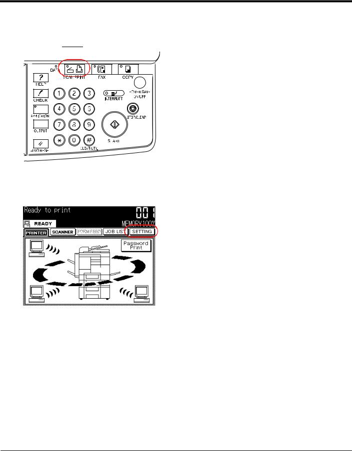
1 Press the 

 button on the control panel.
→ The [Printer basic mode] screen is displayed on the LCD screen.
2 Touch the [SETTING] key on the LCD screen.
→ The [Main Menu] screen is displayed on the LCD screen.
452 |
VI Network (For administrator) |
|
Chapter 18 Setting from the Control Panel |

18-1. Method for setting network from control panel
3
4
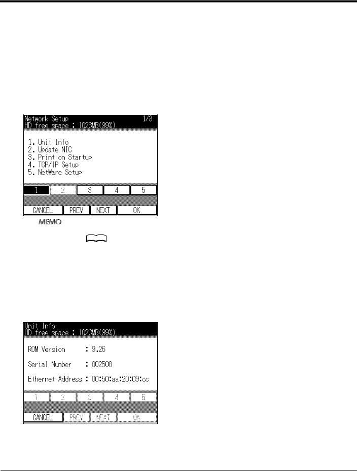
Touch the [5] key on the LCD screen.
Touch the [OK] key on the LCD screen.
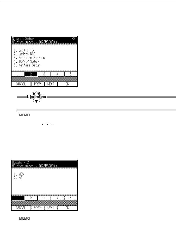
→ The [Network Setup] screen is displayed on the LCD screen.
The following settings are made on the [Network Setup] screen.
Unit Info |
Page 457 |
Update NIC |
Page 458 |
Print on Startup |
Page 462 |
TCP/IP Setup |
Page 464 |
NetWare Setup |
Page 482 |
AppleTalk Setup |
Page 501 |
WINS Setup |
Page 508 |
FTP Setup |
Page 515 |
Email Setup |
Page 520 |
DNS Setup |
Page 535 |
453 |
VI Network (For administrator) |
|
Chapter 18 Setting from the Control Panel |

18-1. Method for setting network from control panel
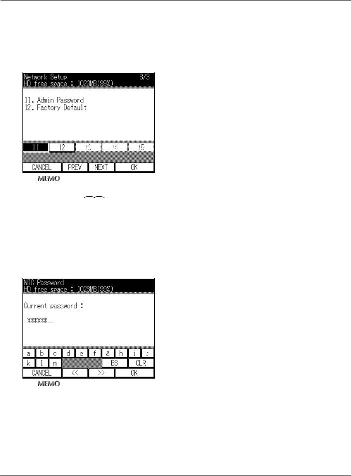
Admin Password |
Page 460 |
Factory Default |
Page 540 |
zTo switch the items displayed on [Network Setup] screen, touch the [PREV] or [NEXT] key on the LCD screen.
5
6
Select the item to set, then touch the [OK] key on the LCD screen.
Set each item and when setting of all the items is complete, touch the [CANCEL] key or
[OK] key.
→ The display returns to the [Network Setup] screen.
7 The [Update NIC] is executed.
zFor the [Update NIC] procedure, refer to [Update NIC] (


 Page 458).
8 Wait until the [Please wait Printer initializing] display on the LCD screen changes to [Ready to print].
9 Switch off the Copier main power, wait about 10 seconds, then switch the power back on again.
→The network setting items are updated with the changed contents.
●After switching Off the Copier main power, if you switch it back on without waiting, the print controller may not operate normally and errors may be displayed.
In this case, if you switch the Copier main power Off again, wait at least 10 seconds or so, then switch the main power On again, the system will operate normally.
454 |
VI Network (For administrator) |
|
Chapter 18 Setting from the Control Panel |
18-1. Method for setting network from control panel
IP address settings
There are the following two methods for setting the IP address etc. for the network controller.
Assigning the IP address automatically with the DHCP server
When managing IP addresses with the DHCP server on the network that the network controller is connected to, there is no need to set a unique IP address for the network controller. The IP address can be acquired automatically from the DHCP server.
Setting a unique IP address for the network controller
When setting individual IP addresses for equipment connected to the network, the IP address assigned to the network controller is set with manual input. In this case, it is also necessary to set the sub-net mask and other information with manual input.
zFor details on management methods for network IP addresses etc., check with the network administrator.
zFor details on making network settings manually, check with the network administrator.
zWhen making network settings manually, in addition to the method explained here using the Copier’s control panel, you can also use a web utility. For details, refer to the Web Utilities user’s manual.
455 |
VI Network (For administrator) |
|
Chapter 18 Setting from the Control Panel |
18-1. Method for setting network from control panel
Character input on LCD screen
When characters must be input on the LCD screen, touch the alphanumeric input keys on the screen.
When you touch [‹‹] or [››] the buttons that can be input are switched.
When you touch [BS], one input character is deleted.
When you touch [CLR], the input characters are all deleted.
456 |
VI Network (For administrator) |
|
Chapter 18 Setting from the Control Panel |
18-2. NIC
After checking the information related to the network controller installed in the print controller and making any necessary changes, finalize the settings. The password used must be changed when the network settings are updated and when the network controller is initialized.
Unit Info
This checks the hardware information for the network.
1 Touch the [1] key on [Network Setup] screen on the LCD screen.
zFor details on the procedure for displaying the [Network Setup] screen, refer to [18-1.Method for setting network from control panel] ( 


 Page 452).
zThe [Network Setup] screen displays with [1] already selected.
2 Touch the [OK] key on the LCD screen.
→ The network controller [ROM Version], [Serial Number] and [Ethernet Address] are displayed.
3 To check information, touch the [CANCEL] key on the LCD screen.
→ The display returns to the [Network Setup] screen.
457 |
VI Network (For administrator) |
|
Chapter 18 Setting from the Control Panel |
18-2. NIC
Update NIC
The [Network Setup] items are updated to the changed contents.
1 Touch the [2] key on [Network Setup] screen on the LCD screen.
● [2] cannot be selected until the contents of the [Network Setup] items have been changed.
zFor details on the procedure for displaying the [Network Setup] screen, refer to [18-1.Method for setting network from control panel] (


 Page 452).
2 Touch the [OK] key on the LCD screen.
→ A screen is displayed to confirm that you want to execute an [Update NIC].
3 Touch the [OK] key on the LCD screen.
→ The screen for inputting the password is displayed.
zTo cancel the [Update NIC], touch the [2] key on the LCD screen, then touch the [OK] key on the LCD screen.
458 |
VI Network (For administrator) |
|
Chapter 18 Setting from the Control Panel |
18-2. NIC
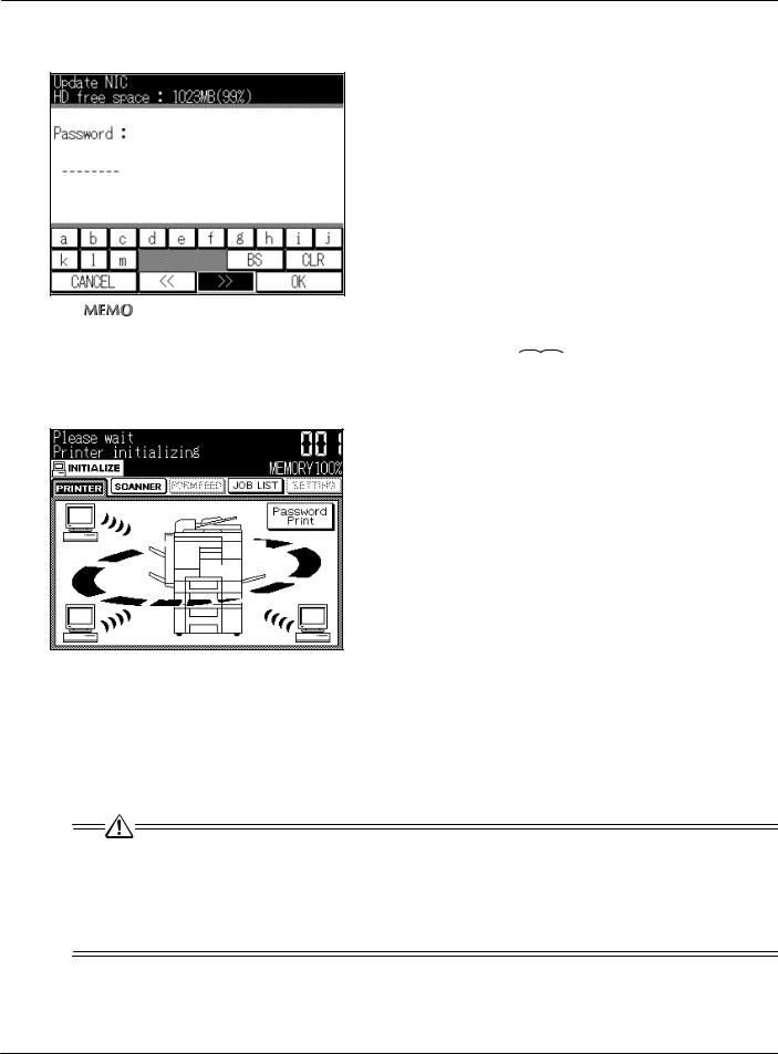
4 Use the alphanumeric keys on the LCD screen to input the password.
zThe default setting for the password is [sysadm].
zFor details on character input, refer to [Character input on LCD screen](


 Page 456).
5 Touch the [OK] key on the LCD screen.
→The [Please wait] message is displayed and the initial operation starts. Wait until [Ready] is displayed and operations end.
6 Switch off the Copier main power, wait about 10 seconds, then switch the power back on again.
→The network setting items are updated with the changed contents.
●The updated settings do not operate normally until the Copier is switched Off, then On again.
●After switching Off the Copier main power, if you switch it back on without waiting, the print controller may not operate normally and errors may be displayed.
In this case, if you switch the Copier main power Off again, wait at least 10 seconds or so, then switch the main power On again, the system will operate normally.
459 |
VI Network (For administrator) |
|
Chapter 18 Setting from the Control Panel |
18-2. NIC
Admin Password
The password to input when changing the network controller settings can be changed.
1 Touch the [11] key on [Network Setup] screen on the LCD screen.
zFor details on the procedure for displaying the [Network Setup] screen, refer to [18-1.Method for setting network from control panel] (


 Page 452).
2
3
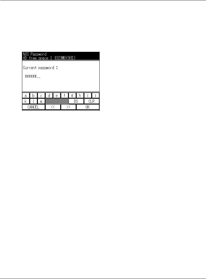
Touch the [OK] key on the LCD screen.
→ The [NIC Password] screen is displayed.
Touch the alphanumeric input keys on the LCD screen and input the current password at [Current password].
zThe default setting for the password is [sysadm].
zIf you have forgotten your current password, by inputting [3069] for the [Current password input], the new password input screen is displayed.
The only password that can be displayed using [3069] is the NIC password.
4 Touch the [OK] key on the LCD screen.
→ The [NIC Password] screen is displayed.
460 |
VI Network (For administrator) |
|
Chapter 18 Setting from the Control Panel |
18-2. NIC
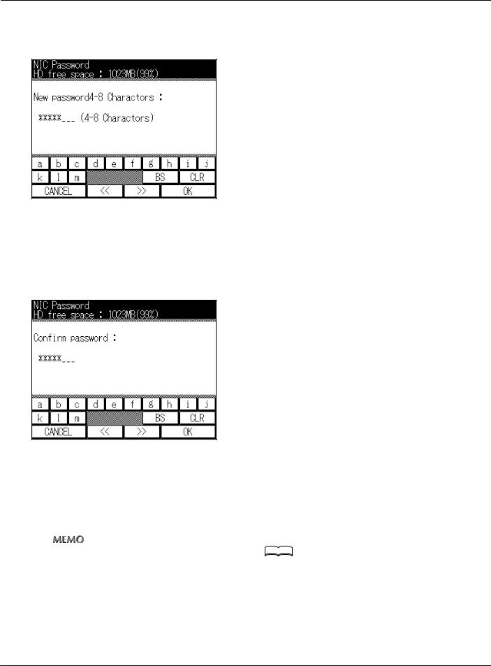
5 Touch the alphanumeric input keys on the LCD screen to input a new password 4-8 characters long.
6
7
8
9
Touch the [OK] key on the LCD screen.
→ The screen for inputting the new password is displayed.
Use the alphanumeric keys on the LCD screen to input the new password again.
Touch the [OK] key on the LCD screen.
→ The display returns to the [Network Setup] screen.
The [Update NIC] is executed.
zFor the [Update NIC] procedure, refer to [Update NIC]( 


 Page 458).
→The network setting items are updated with the changed contents.
461 |
VI Network (For administrator) |
|
Chapter 18 Setting from the Control Panel |
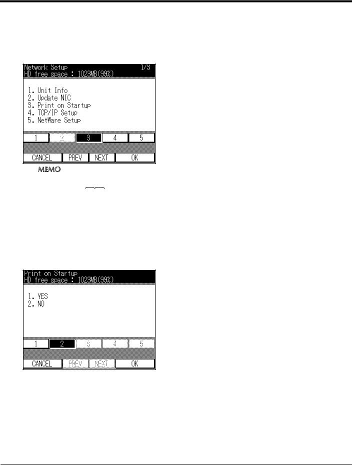
18-3. Print on startup
This sets whether or not to print a network settings list automatically when the power for the Copier is switched on.
1 Touch the [3] key on [Network Setup] screen on the LCD screen.
zFor details on the procedure for displaying the [Network Setup] screen, refer to [18-1.Method for setting network from control panel] (


 Page 452).
2
3
Touch the [OK] key on the LCD screen.
→ The [Print on Startup] screen is displayed.
To print the network settings list when the power is switched on, touch the [1] key on the LCD screen; to not print, touch the [2] key on the LCD screen.
4 Touch the [OK] key on the LCD screen.
→ The display returns to the [Network Setup] screen.
462 |
VI Network (For administrator) |
|
Chapter 18 Setting from the Control Panel |

18-3. Print on startup
5 The [Update NIC] is executed.
→ The network setting items are updated with the changed contents.
zFor the [Update NIC] procedure, refer to [Update NIC] (


 Page 458).
463 |
VI Network (For administrator) |
|
Chapter 18 Setting from the Control Panel |
18-4. TCP/IP setup
The information required for using the print controller in the TCP/IP environment is set.
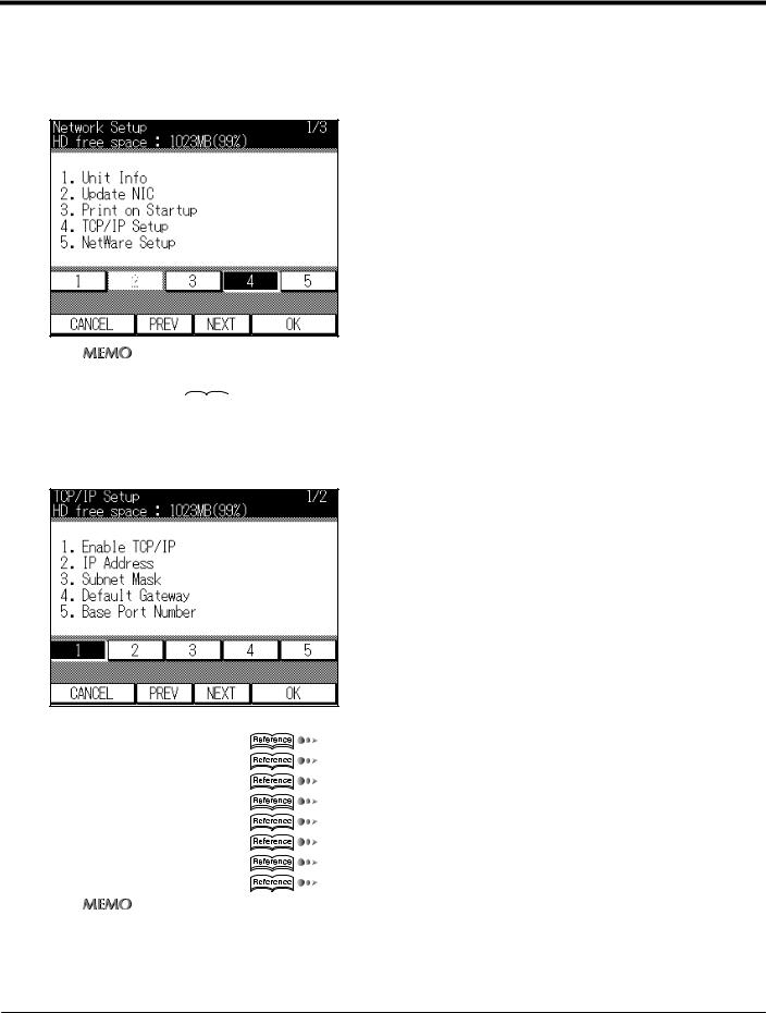
1 Touch the [4] key on [Network Setup] screen on the LCD screen.
zFor details on the procedure for displaying the [Network Setup] screen, refer to [18-1.Method for setting network from control panel] (


 Page 452).
2 Touch the [OK] key on the LCD screen.
→ The [TCP/IP Setup] screen is displayed.
The following settings are made on this screen.
Enable TCP/IP |
Page 466 |
IP Address |
Page 468 |
Subnet Mask |
Page 470 |
Default Gateway |
Page 472 |
Base Port Number |
Page 474 |
Enable DHCP |
Page 476 |
IP Addr.in NVRAM |
Page 478 |
LPD Banner |
Page 480 |
zTo switch the items displayed on the [TCP/IP Setup] screen, touch the [PREV] key or [NEXT] key on the LCD screen.
464 |
VI Network (For administrator) |
|
Chapter 18 Setting from the Control Panel |
18-4. TCP/IP setup
3
4
When the settings for all the items is complete, touch the [CANCEL] key on the LCD
screen.
→ The [Network Setup] screen is displayed.
The [Update NIC] is executed.
zFor the [Update NIC] procedure, refer to [Update NIC] (


 Page 458).
465 |
VI Network (For administrator) |
|
Chapter 18 Setting from the Control Panel |
18-4. TCP/IP setup
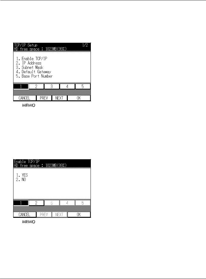
Enable TCP/IP
This sets whether or not to enable TCP/IP usage.
1 Touch the [1] key on [TCP/IP Setup] screen on the LCD screen.
zThe [TCP/IP Setup] screen displays with [1] already selected.
2
3
Touch the [OK] key on the LCD screen.
→ The screen for setting TCP/IP usage is displayed.
To disable TCP/IP settings, touch the [2] key on the LCD screen; to enable them, touch the [1] key on the LCD screen.
zThe factory default is [Yes].
4 Touch the [OK] key on the LCD screen.
→ The display returns to the [TCP/IP Setup] screen.
466 |
VI Network (For administrator) |
|
Chapter 18 Setting from the Control Panel |

18-4. TCP/IP setup
5 When setting another item, do so now.
zFor details on the operation methods for other settings, refer to the respective page.
6 The [Update NIC] is executed.
→ The network setting items are updated with the changed contents.
zFor the [Update NIC] procedure, refer to [Update NIC](


 Page 458).
467 |
VI Network (For administrator) |
|
Chapter 18 Setting from the Control Panel |
18-4. TCP/IP setup
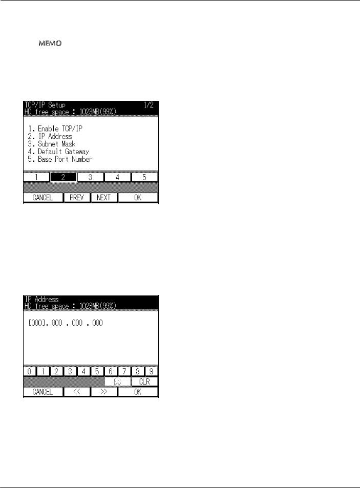
IP Address
The IP address for the print controller network controller is registered.
zWhen using the DHCP server for IP address management, in [DHCP usage] enabled, the IP address acquired with DHCP is displayed.
1
2
3
Touch the [2] key on [TCP/IP Setup] screen on the LCD screen.
Touch the [OK] key on the LCD screen.
→ The [IP Address] screen is displayed.
Touch numeric keys on the LCD screen to input the IP address.
Specify four numbers from 0-255 delimited in [.(dot)]. When you touch [‹‹] or [››], the input position is moved.
IP address input example:192.168.00.10
4 Touch the [OK] key on the LCD screen.
→ The display returns to the [TCP/IP Setup] screen.
468 |
VI Network (For administrator) |
|
Chapter 18 Setting from the Control Panel |

18-4. TCP/IP setup
5 When setting another item, do so now.
zFor details on the operation methods for other settings, refer to the respective page.
6 The [Update NIC] is executed.
→ The network setting items are updated with the changed contents.
zFor the [Update NIC] procedure, refer to [Update NIC](


 Page 458).
469 |
VI Network (For administrator) |
|
Chapter 18 Setting from the Control Panel |
18-4. TCP/IP setup
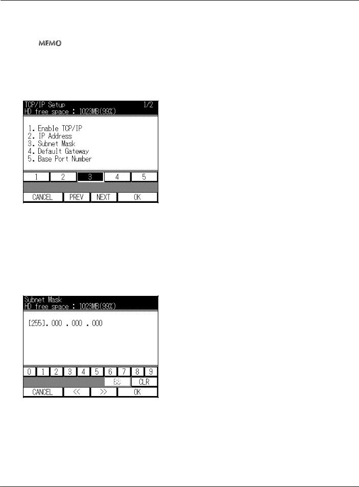
Subnet Mask
This inputs the subnet mask for the network to which the print controller is connected.
zWhen using the DHCP server for IP address management, in [DCHP usage] enabled, the subnet mask acquired with DHCP is displayed.
1
2
3
Touch the [3] key on [TCP/IP Setup] screen on the LCD screen.
Touch the [OK] key on the LCD screen.
→ The [Subnet Mask] screen is displayed.
Touch numeric keys on the LCD screen to input the subnet mask.
Specify four numbers from 0-255 delimited in [.(dot)]. When you touch [‹‹] or [››], the input position is moved.
Subnet mask input example:255.255.255.0
4 Touch the [OK] key on the LCD screen.
→ The display returns to the [TCP/IP Setup] screen.
470 |
VI Network (For administrator) |
|
Chapter 18 Setting from the Control Panel |

18-4. TCP/IP setup
5 When setting another item, do so now.
zFor details on the operation methods for other settings, refer to the respective page.
6 The [Update NIC] is executed.
→ The network setting items are updated with the changed contents.
zFor the [Update NIC] procedure, refer to [Update NIC](


 Page 458).
471 |
VI Network (For administrator) |
|
Chapter 18 Setting from the Control Panel |
18-4. TCP/IP setup
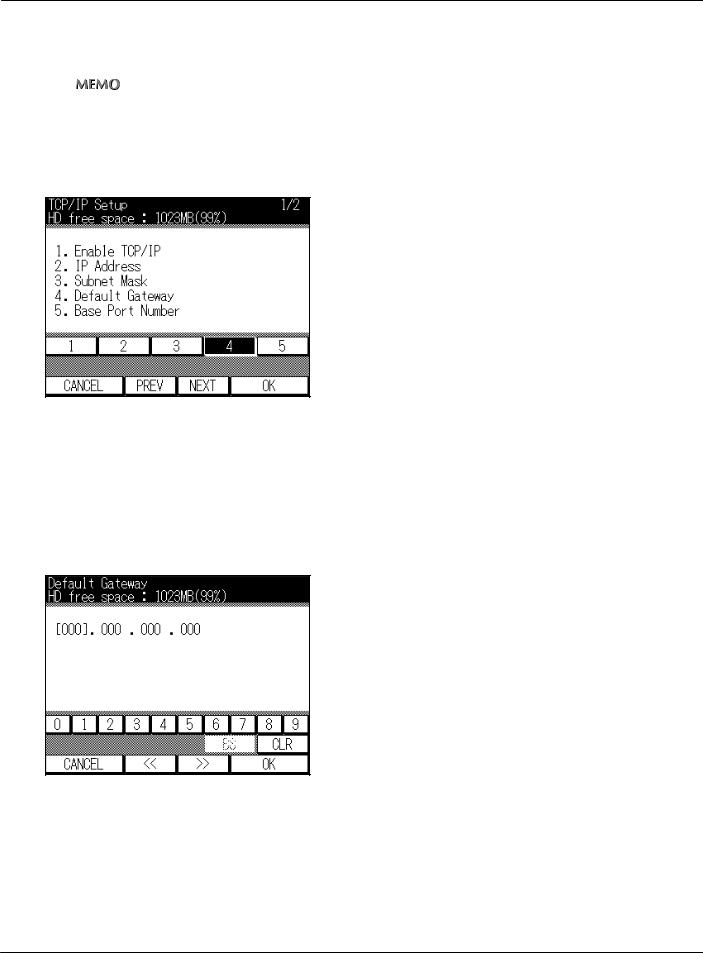
Default Gateway
This inputs the gateway for the network to which the print controller is connected.
zWhen using the DHCP server for IP address management, in [DHCP usage] enabled, the gateway address acquired with DHCP is displayed.
1
2
3
Touch the [4] key on [TCP/IP Setup] screen on the LCD screen.
Touch the [OK] key on the LCD screen.
→ The [Default Gateway] screen is displayed.
Touch numeric keys on the LCD screen to input the gateway address.
Specify four numbers from 0-255 delimited in [.(dot)]. When you touch [‹‹] or [››], the input position is moved.
Gateway address input example:192.168.0.1
4 Touch the [OK] key on the LCD screen.
→ The display returns to the [TCP/IP Setup] screen.
472 |
VI Network (For administrator) |
|
Chapter 18 Setting from the Control Panel |

18-4. TCP/IP setup
5 When setting another item, do so now.
zFor details on the operation methods for other settings, refer to the respective page.
6 The [Update NIC] is executed.
→ The network setting items are updated with the changed contents.
zFor the [Update NIC] procedure, refer to [Update NIC](


 Page 458).
473 |
VI Network (For administrator) |
|
Chapter 18 Setting from the Control Panel |
18-4. TCP/IP setup
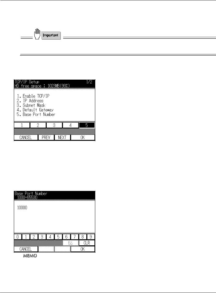
Base Port Number
This specifies any value as the base port number.
●If the port number is changed inappropriately, this may create obstructions for the network. Do not change the port number unless necessary.
1
2
3
Touch the [5] key on [TCP/IP Setup] screen on the LCD screen.
Touch the [OK] key on the LCD screen.
→ The [Base Port Number] screen is displayed.
Touch numeric keys on the LCD screen to input a new base port number from 1000 to 65530.
zThe factory default is [10000].
4 Touch the [OK] key on the LCD screen.
→ The display returns to the [TCP/IP Setup] screen.
474 |
VI Network (For administrator) |
|
Chapter 18 Setting from the Control Panel |
 Loading...