

Page 1

Operation & Maintenance
Operation & Maintenance
Operation & MaintenanceOperation & Maintenance
Manual
Manual
ManualManual
SEAM039100T
WD600
WHEEL DOZER
SERIAL NUMBERS
This material is proprietary to Komatsu America International Company and is not to be reproduced, used, or
disclosed except in accordance with written authorization from Komatsu America International Company.
It is our policy to improve our products whenever it is possible and practical to do so. We reserve the right to
make changes or improvements at any time without incurring any obligation to install such changes on
products sold previously.
Due to this continuous program of research and development, revisions may be made to this publication. It
is recommended that customers contact their distributor for information on the latest revision.
WD600-3 - 50001
-3
and up
December 2002
Copyright 2002 Komatsu
DataKom Publishing Division
Page 2

.
1 - 1
Page 3
.
FOREWORD
FOREWORD
FOREWORD
Operators
and
maintenance
personnel
must
always
doasfollows
before
beginning
operation
or
maintenance.
Always
be
suretoread
and
understand
this
manual
thoroughly
before
performing
operation
and
maintenance.
Read
the
safety
messages
given
in
this
manual
and
the
safety
labels
affixed
to
the
machine
thoroughly
andbesure
that
you
understand
them
fully.
Keep
this
manual
at
the
storage
location
for
the
Operation
and
Maintenance
Manual
given
below,
and
have
all
personnel
readitperiodically.
Ifthis
manual
has
been
lostorhas
become
dirty
and
cannot
be
read,
request
a
replacement
manual
immediately
from
Komatsu
or
your
Komatsu
distributor.
If
you
sell
the
machine,
be
suretogive
this
manual
to
the
new
owners
together
with
the
machine.
Komatsu
delivers
machines
that
comply
with
all
applicable
regulations
and
standards
of
the
country
to
which
it
has
been
shipped.
If
this
machine
has
been
purchased
in
another
country
or
purchased
from
someone
in
another
country,
it
may
lack
certain
safety
devices
and
specifications
that
are
necessary
for
useinyour
country.
If
there
is
any
question
about
whether
your
product
complies
with
the
applicable
standards
and
regulations
of
your
country,
consult
Komatsu
or
your
Komatsu
distributor
before
operating
the
machine.
1 - 2
This manual provides rules and guidelines which will help you use this machine safely and effectively. The
precautions in this manual must be followed at all times when performing operation and maintenance. Most
accidents are caused by the failure to follow fundamental safety rules for the operation and maintenance of
machines. Accidents can be prevented by knowing beforehand conditions that may cause hazard when performing
operation and maintenance.
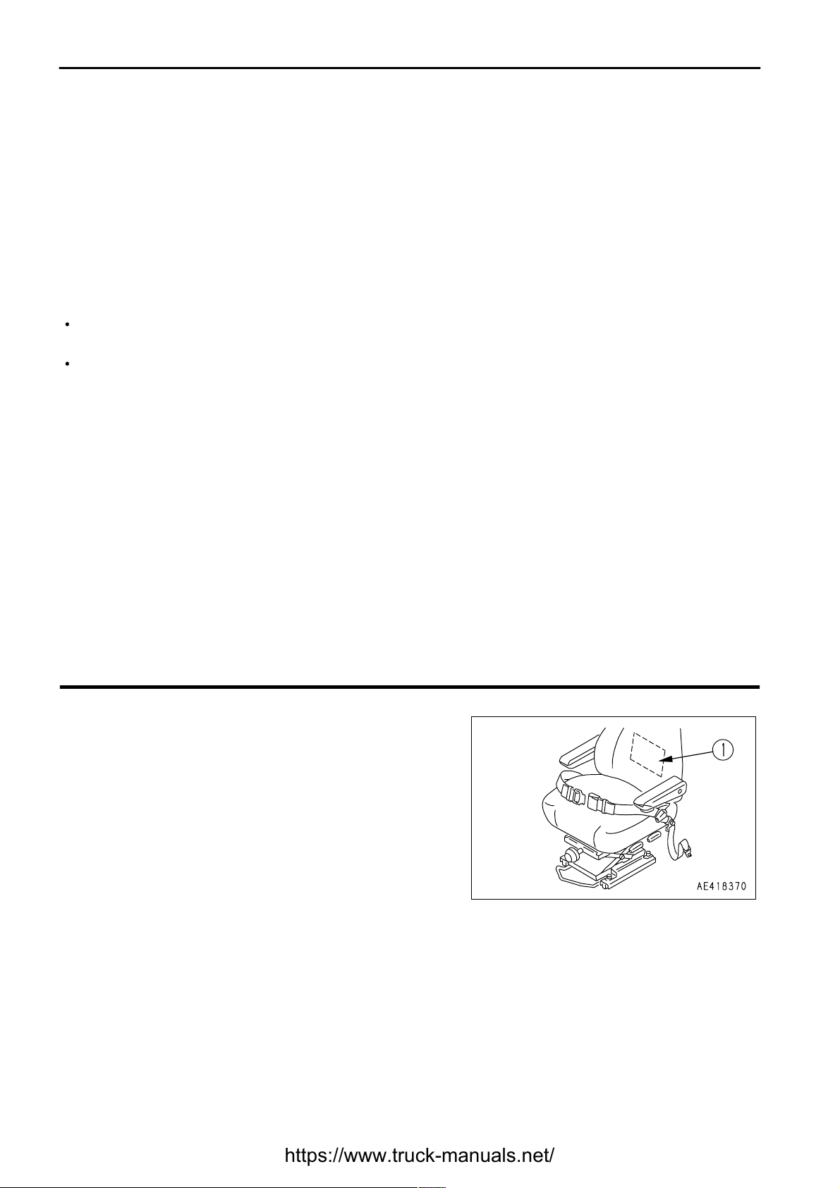
Storage location for the Operation and Maintenance Manual:
Pocket (1) at rear of operator's seat
Page 4
.
FOREWORD
FOREWORD
1 - 3
Page 5
.
FOREWORD
FOREWORD
1 - 4
Page 6

.
FOREWORD
SAFETY INFORMATION
SAFETY INFORMATION
Signal
words
Example
of
safety
message
using
signal
word
When
standing
up
from
the
operator's
seat,
always
place
the
safety
lock
leverinthe
LOCK
position.
If
you
accidentally
touch
the
control
levers
when
they
are
not
locked,
this
may
cause
a
serious
injury
or
death.
Other
signal
words
1 - 5
To enable you to use this machine safely, safety precautions and labels are given in this manual and affixed to the
machine to give explanations of situations involving potential hazards and of the methods of avoiding such
situations.
The following signal words are used to inform you that there is a potential hazardous situation that may lead to
personal injury or damage.
In this manual and on machine labels, the following signal words are used to express the potential level of hazard.
Indicates an imminently hazardous situation which, if not avoided, will result in death or
serious injury.
Indicates a potentially hazardous situation which, if not avoided, could result in death or
serious injury.
Indicates a potentially hazardous situation which, if not avoided, may result in minor or
moderate injury. This word is used also to alert against unsafe practices that may cause
property damage.
In addition to the above, the following signal words are used to indicate precautions that should be followed to
protect the machine or to give information that is useful to know.
This word is used for precautions that must be taken to avoid actions which could shorten
the life of the machine.
This word is used for information that is useful to know.
Page 7
.
FOREWORD
SAFETY INFORMATION
Safety
labels
Example
of
safety
label
using
words
Safety
labels
using
pictogram
1 - 6
Safety labels are affixed to the machine to inform the operator or maintenance worker on the spot when carrying out
operation or maintenance of the machine that may involve hazard.
This machine uses "Safety labels using words" and "Safety labels using pictograms" to indicate safety procedures.
Safety pictograms use a picture to express a level of hazardous
condition equivalent to the signal word. These safety pictograms
use pictures in order to let the operator or maintenance worker
understand the level and type of hazardous condition at all times.
Safety pictograms show the type of hazardous condition at the top
or left side, and the method of avoiding the hazardous condition at
the bottom or right side. In addition, the type of hazardous condition
is displayed inside a triangle and the method of avoiding the
hazardous condition is shown inside a circle.
Komatsu cannot predict every circumstance that might involve a potential hazard in operation and maintenance.
Therefore, the safety messages in this manual and on the machine may not include all possible safety precautions.
If any procedures or actions not specifically recommended or allowed in this manual are used, it is your responsibility
to take the necessary steps to ensure safety.
In no event should you engage in prohibited uses or actions described in this manual.
The explanations, values, and illustrations in this manual were prepared based on the latest information available
at that time. Continuing improvements in the design of this machine can lead to changes in detail which may not
be reflected in this manual. Consult Komatsu or your Komatsu distributor for the latest available information of your
machine or for questions regarding information in this manual.
The numbers in circles in the illustrations correspond to the numbers in ( ) in the text. (For example: j -> (1))
Page 8
.
FOREWORD
INTRODUCTION
INTRODUCTION
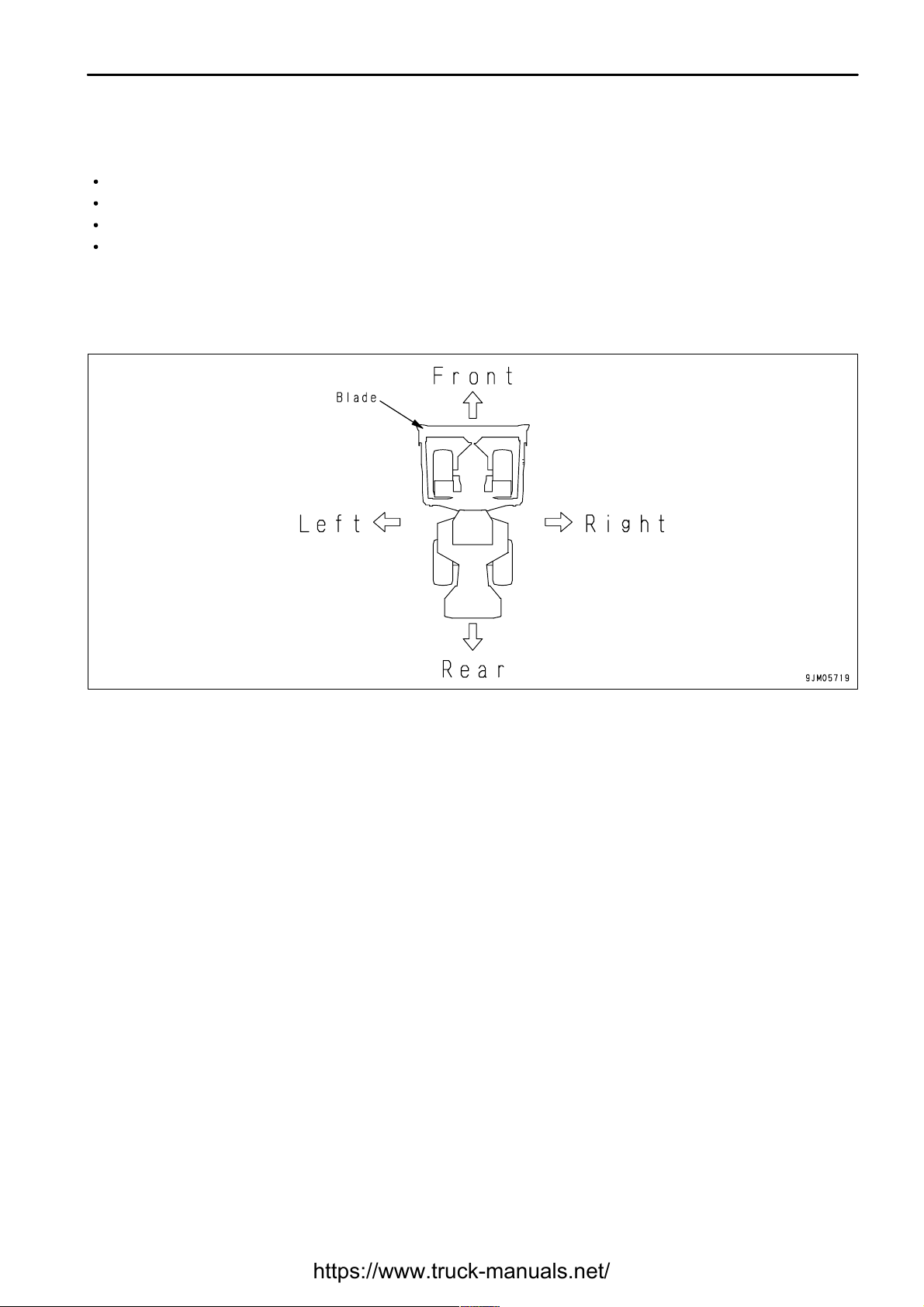
FRONT/REAR, LEFT/RIGHT DIRECTIONS OF MACHINE
1 - 7
This Komatsu machine is designed to be used mainly for the following work:
Ditching
Smoothing
Dozing
Felling and uprooting
For details of the operating procedure, see "WORK POSSIBLE USING WHEEL DOZER (PAGE 3-66)".
In this manual, the directions of the machine (front, rear, left, right) are determined according to the view from the
operator's seat in the direction of travel (front) of the machine.
Page 9
.
FOREWORD
NECESSARY INFORMATION
NECESSARY INFORMATION
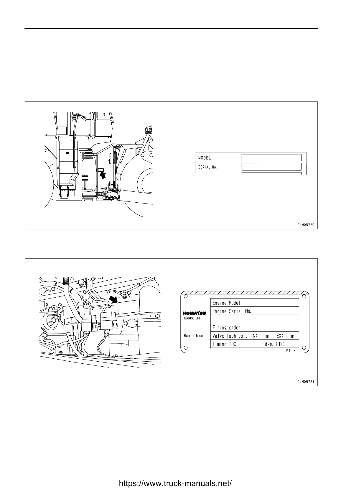
MACHINE SERIAL NO. PLATE AND POSITION
ENGINE SERIAL NO. PLATE AND POSITION
1 - 8
When requesting service or ordering replacement parts, please inform your Komatsu distributor of the following
items.
On the center right of the front frame.
On the upper left of the cylinder block, when seen from the fan side.
Page 10
.
FOREWORD
NECESSARY INFORMATION
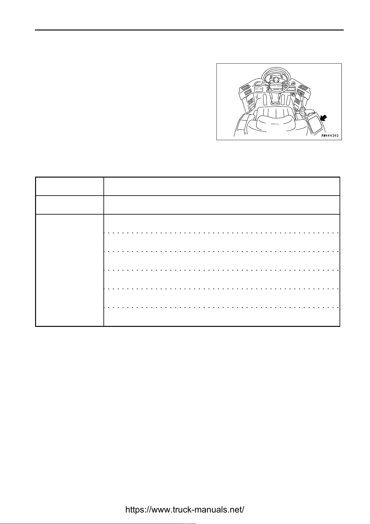
POSITION OF SERVICE METER
TABLE TO ENTER SERIAL NO. AND DISTRIBUTOR
1 - 9
On the lower right of maintenance monitor.
Machine serial No.
Engine serial No.
Distributor name
Address
Service Personnel
Phone/Fax
Page 11

.
FOREWORD
CONTENTS
CONTENTS
1 - 10
FOREWORD 1- 1
FOREWORD 1- 2
SAFETY INFORMATION 1- 5
INTRODUCTION 1- 7
FRONT/REAR, LEFT/RIGHT DIRECTIONS OF MACHINE 1- 7
NECESSARY INFORMATION 1- 8
MACHINE SERIAL NO. PLATE AND POSITION 1- 8
ENGINE SERIAL NO. PLATE AND POSITION 1- 8
POSITION OF SERVICE METER 1- 9
TABLE TO ENTER SERIAL NO. AND DISTRIBUTOR 1- 9
SAFETY 2- 1
SAFETY 2- 2
SAFETY LABELS 2- 4
LOCATION OF SAFETY LABELS 2- 5
GENERAL PRECAUTIONS 2- 11
PRECAUTIONS FOR OPERATION 2- 19
STARTING ENGINE 2- 19
OPERATION 2- 21
TRANSPORTATION 2- 26
BATTERY 2- 27
TOWING 2- 29
PRECAUTIONS FOR MAINTENANCE 2- 30
PRECAUTIONS WITH TIRES 2- 36
OPERATION 3- 1
GENERAL VIEW 3- 2
GENERAL VIEW OF MACHINE 3- 2
GENERAL VIEW OF CONTROLS AND GAUGES 3- 3
EXPLANATION OF COMPONENTS 3- 5
MACHINE MONITOR 3- 5
SWITCHES 3- 18
CONTROL LEVERS, PEDALS 3- 27
STEERING COLUMN TILT LEVER 3- 32
CAP WITH LOCK 3- 33
SAFETY BAR 3- 34
TOWING PIN 3- 34
GREASE PUMP 3- 35
BACKUP ALARM 3- 35
DUST INDICATOR 3- 35
CAB DOOR OPEN LOCK 3- 36
TOOL BOX 3- 36
OIL FILLER LOCATION 3- 36
FUSE 3- 36
SLOW-BLOW FUSE 3- 38
LUNCH BOX TRAY 3- 38
TAKING OFF POWER 3- 38
OPERATION 3- 39
CHECK BEFORE STARTING ENGINE, ADJUST 3- 39
STARTING ENGINE 3- 53
OPERATIONS AND CHECKS AFTER STARTING ENGINE 3- 55
Page 12

.
FOREWORD
CONTENTS
1 - 11
STOPPING ENGINE 3- 57
CHECK AFTER STOPPING ENGINE 3- 57
MOVING MACHINE OFF (DIRECTIONAL, SPEED), STOPPING 3- 58
TURNING 3- 63
OPERATION OF WORK EQUIPMENT 3- 63
WORK POSSIBLE USING WHEEL DOZER 3- 66
PRECAUTIONS FOR OPERATION 3- 66
PARKING MACHINE 3- 68
CHECKS AFTER COMPLETION OF OPERATION 3- 69
LOCKING 3- 69
HANDLING THE TIRES 3- 70
TRANSPORTATION 3- 72
LOADING, UNLOADING WORK 3- 72
PRECAUTIONS FOR LOADING 3- 72
LIFTING MACHINE 3- 73
COLD WEATHER OPERATION 3- 74
PRECAUTIONS FOR LOW TEMPERATURE 3- 74
PRECAUTIONS AFTER COMPLETION OF WORK 3- 75
AFTER COLD WEATHER 3- 76
WARMING-UP OPERATION FOR STEERING HYDRAULIC CIRCUIT IN COLD WEATHER 3- 76
LONG-TERM STORAGE 3- 77
BEFORE STORAGE 3- 77
DURING STORAGE 3- 77
AFTER STORAGE 3- 77
TROUBLESHOOTING 3- 78
WHEN MACHINE RUNS OUT OF FUEL 3- 78
TOWING THE MACHINE 3- 79
IF BATTERY IS DISCHARGED 3- 82
OTHER TROUBLE 3- 85
MAINTENANCE 4- 1
GUIDES TO MAINTENANCE 4- 2
OUTLINES OF SERVICE 4- 4
HANDLING OIL, FUEL, COOLANT, AND PERFORMING OIL CLINIC 4- 4
OUTLINE OF ELECTRIC SYSTEM 4- 6
WEAR PARTS 4- 7
WEAR PARTS LIST 4- 7
USE OF FUEL, COOLANT AND LUBRICANTS ACCORDING TO AMBIENT TEMPERATURE 4- 8
PROPER SELECTION OF FUEL, COOLANT AND LUBRICANTS 4- 8
STANDARD TIGHTENING TORQUES FOR BOLTS AND NUTS 4- 12
TORQUE LIST 4- 12
PERIODIC REPLACEMENT OF SAFETY CRITICAL PARTS 4- 13
SAFETY CRITICAL PARTS 4- 13
MAINTENANCE SCHEDULE CHART 4- 14
MAINTENANCE SCHEDULE CHART 4- 14
SERVICE PROCEDURE 4- 16
INITIAL 250 HOURS SERVICE 4- 16
INITIAL 2000 HOURS SERVICE 4- 16
WHEN REQUIRED 4- 17
CHECK BEFORE STARTING 4- 33
EVERY 50 HOURS SERVICE 4- 34
Page 13

.
FOREWORD
CONTENTS
1 - 12
EVERY 100 HOURS SERVICE 4- 35
EVERY 250 HOURS SERVICE 4- 37
EVERY 500 HOURS SERVICE 4- 44
EVERY 1000 HOURS SERVICE 4- 49
EVERY 2000 HOURS SERVICE 4- 53
EVERY 4000 HOURS SERVICE 4- 60
SPECIFICATIONS 5- 1
SPECIFICATIONS 5- 2
ATTACHMENTS, OPTIONS 6- 1
HANDLING AUTOMATIC SHIFT SYSTEM 6- 2
METHOD OF OPERATION 6- 2
PRECAUTION WHEN CHANGING DIRECTION 6- 3
HANDLING JOYSTICK STEERING SYSTEM 6- 4
STRUCTURE AND FUNCTION OF JOYSTICK STEERING 6- 4
OPERATION METHOD OF JOYSTICK STEERING SYSTEM 6- 8
PRECAUTIONS FOR STEERING WITH JOYSTICK 6- 10
ADJUSTMENT OF JOYSTICK CONSOLE 6- 11
HANDLING AIR-SUSPENSION SEAT 6- 12
SEAT ADJUSTMENT 6- 12
FAILURE DISPLAY ON MAIN MONITOR 6- 14
FAILURE CODE ON MAIN MONITOR 6- 14
FAILURE CODE ON AUTOMATIC SHIFT AND JOYSTICK STEERING SYSTEM 6- 14
CAR RADIO 6- 15
EXPLANATION OF COMPONENTS 6- 15
METHOD OF USE 6- 18
PRECAUTIONS WHEN USING 6- 20
AM/FM RADIO-CASSETTE STEREO 6- 21
EXPLANATION OF COMPONENTS 6- 21
METHOD OF OPERATION 6- 26
PRECAUTIONS FOR USE 6- 28
AIR CONDITIONER 6- 29
GENERAL LOCATIONS AND FUNCTION OF CONTROL PANEL 6- 29
METHOD OF OPERATION 6- 31
HANDLING TORQUE CONVERTER LOCK-UP 6- 33
GENERAL LOCATIONS 6- 33
METHOD OF OPERATION 6- 34
TRAVEL SPEED LIMIT FUNCTION 6- 34
INDEX 7- 1
Page 14

.
2 - 1
Page 15

.
SAFETY
SAFETY
SAFETY
2 - 2
SAFETY LABELS 2- 4
LOCATION OF SAFETY LABELS 2- 5
GENERAL PRECAUTIONS
SAFETY RULES 2- 11
IF ABNORMALITIES ARE FOUND 2- 11
CLOTHING AND PERSONAL PROTECTIVE ITEMS 2- 11
FIRE EXTINGUISHER AND FIRST AID KIT 2- 11
SAFETY FEATURES 2- 11
KEEP MACHINE CLEAN 2- 12
INSIDE OPERATOR'S COMPARTMENT 2- 12
ALWAYS APPLY LOCK WHEN LEAVING OPERATOR'S SEAT 2- 12
HANDRAILS AND STEPS 2- 13
MOUNTING AND DISMOUNTING 2- 13
NO PEOPLE ON ATTACHMENTS 2- 13
DO NOT GET CAUGHT IN ARTICULATED PORTION 2- 14
PREVENTION OF BURNS 2- 14
FIRE PREVENTION 2- 15
ACTION IF FIRE OCCURS 2- 15
WINDOW WASHER LIQUID 2- 16
PRECAUTIONS WHEN USING ROPS (Roll Over Protective Structure) 2- 16
PRECAUTIONS FOR ATTACHMENTS 2- 16
UNAUTHORIZED MODIFICATION 2- 16
SAFETY AT WORKSITE 2- 16
WORKING ON LOOSE GROUND 2- 17
DO NOT GO CLOSE TO HIGH-VOLTAGE CABLES 2- 17
ENSURE GOOD VISIBILITY 2- 18
PRECAUTIONS RELATED TO VENTILATION EXHAUST GAS 2- 18
CHECKING SIGNALMAN'S SIGNALS AND SIGNS 2- 18
EMERGENCY EXIT FROM OPERATOR'S CAB 2- 18
VENTILATION FOR ENCLOSED AREAS 2- 18
Page 16

.
SAFETY
SAFETY
2 - 3
PRECAUTIONS FOR OPERATION 2- 19
BEFORE STARTING ENGINE 2- 19
CHECKS BEFORE STARTING ENGINE 2- 19
PRECAUTIONS WHEN STARTING 2- 19
PRECAUTIONS IN COLD AREAS 2- 20
OPERATION 2- 21
CHECKS BEFORE STARTING ENGINE 2- 21
PRECAUTIONS WHEN TRAVELING IN FORWARD OR REVERSE 2- 21
PRECAUTIONS WHEN TRAVELING 2- 22
TRAVELING ON SLOPES 2- 23
PROHIBITED OPERATIONS 2- 23
PRECAUTIONS WHEN OPERATING 2- 24
METHODS OF USING BRAKE 2- 24
OPERATE CAREFULLY ON SNOW 2- 24
PARKING MACHINE 2- 25
TRANSPORTATION 2- 26
LOADING AND UNLOADING 2- 26
SHIPPING 2- 26
BATTERY 2- 27
BATTERY HAZARD PREVENTION 2- 27
STARTING WITH BOOSTER CABLES 2- 28
TOWING 2- 29
PRECAUTIONS FOR MAINTENANCE 2- 30
WARNING TAG 2- 30
KEEP WORK PLACE CLEAN AND TIDY 2- 30
APPOINT LEADER WHEN WORKING WITH OTHERS 2- 30
MAINTENANCE WITH ENGINE RUNNING 2- 30
TWO WORKERS FOR MAINTENANCE WHEN ENGINE IS RUNNING 2- 32
PROPER TOOLS 2- 32
WORK EQUIPMENT SUPPORT 2- 33
ACCUMULATOR 2- 33
PERSONNEL 2- 33
ATTACHMENTS 2- 33
NOISE 2- 33
PRECAUTIONS WHEN USING HAMMER 2- 34
REPAIR WELDING 2- 34
REMOVING BATTERY TERMINAL 2- 34
PRECAUTIONS WITH HIGH-PRESSURE OIL 2- 34
HANDLING HIGH-PRESSURE HOSES 2- 35
WASTE MATERIALS 2- 35
MAINTENANCE OF AIR CONDITIONER 2- 35
COMPRESSED AIR 2- 35
PERIODIC REPLACEMENT OF SAFETY CRITICAL PARTS 2- 35
PRECAUTIONS WITH TIRES 2- 36
HANDLING TIRES 2- 36
PRECAUTIONS WHEN STORING TIRE 2- 36
Page 17

.
SAFETY
SAFETY LABELS
SAFETY LABELS
2 - 4
The following safety labels are used on this machine. Be sure that you fully understand the correct position and
content of these safety labels.
To ensure that the content of these safety labels can be read properly, be sure that they are in the correct place and
always keep them clean. When cleaning them, use soap and water. Do not use organic solvents or gasoline.
These may cause the safety labels to peel off.
If the safety labels are damaged or lost, or cannot be read, replace them with new parts. For details of the part
numbers, see this manual or check on the actual part, and order the new part from your Komatsu distributor.
There are also other labels in addition to the safety labels. Handle these labels in the same way.
Page 18
.
SAFETY
SAFETY LABELS
LOCATION OF SAFETY LABELS
2 - 5
Page 19
.
SAFETY
SAFETY LABELS
2 - 6
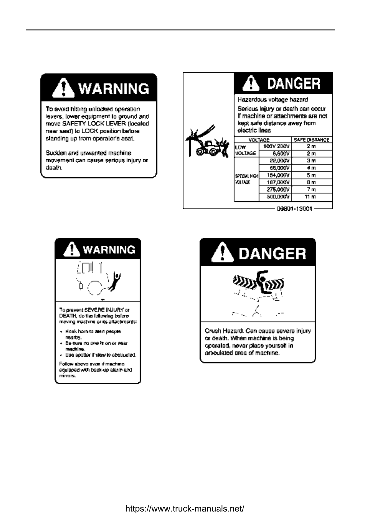
(1) Precautions for safety lock lever (2) Precautions for electric shock (09801-13001)
(3) Precautions when traveling in reverse (4) Do not enter
Page 20
.
SAFETY
SAFETY LABELS
2 - 7
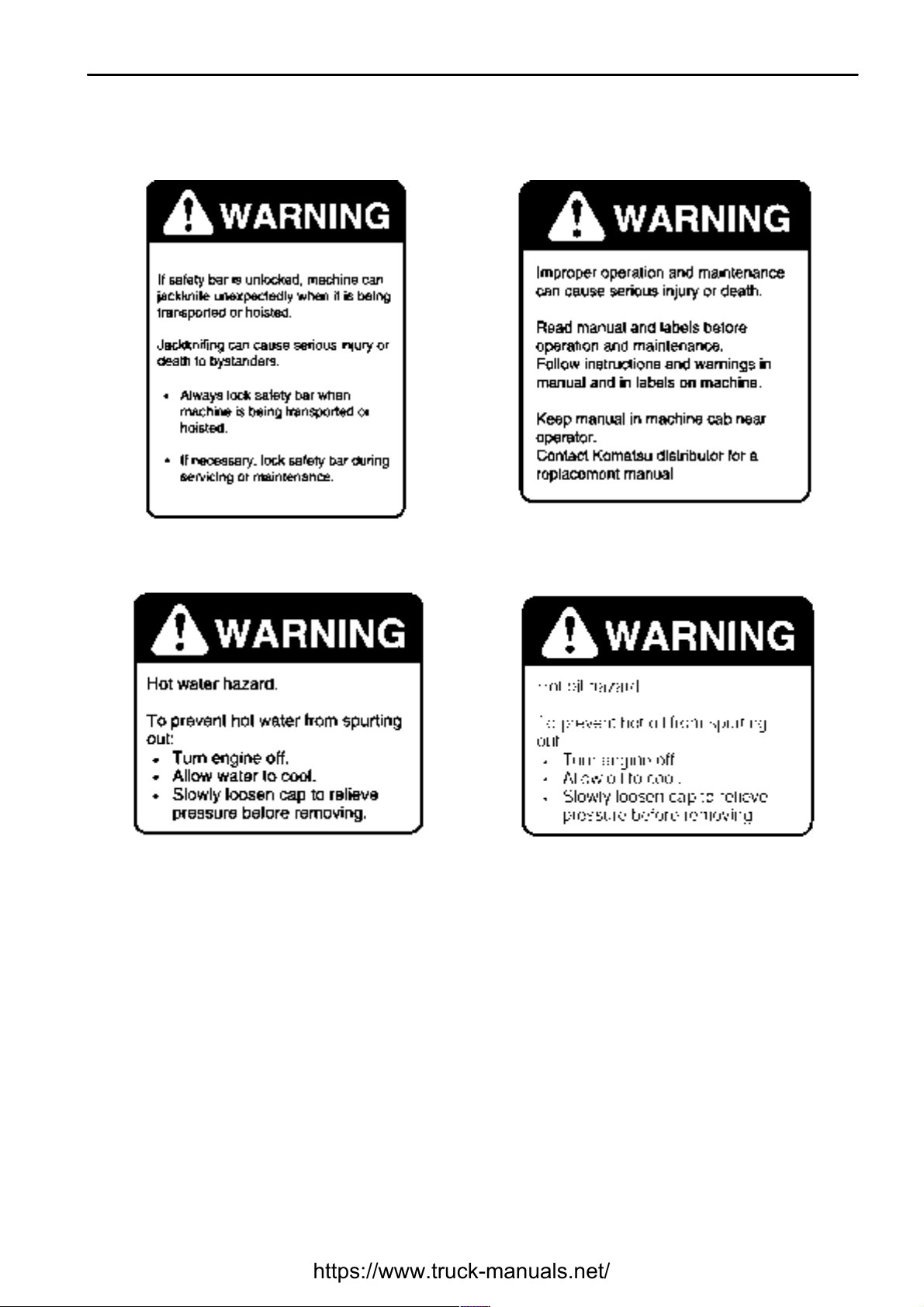
(5) Precautions for safety bar (6) Precautions before starting
(7) Precautions when coolant is at high temperature (8) Precautions when oil is at high temperature
Page 21
.
SAFETY
SAFETY LABELS
2 - 8
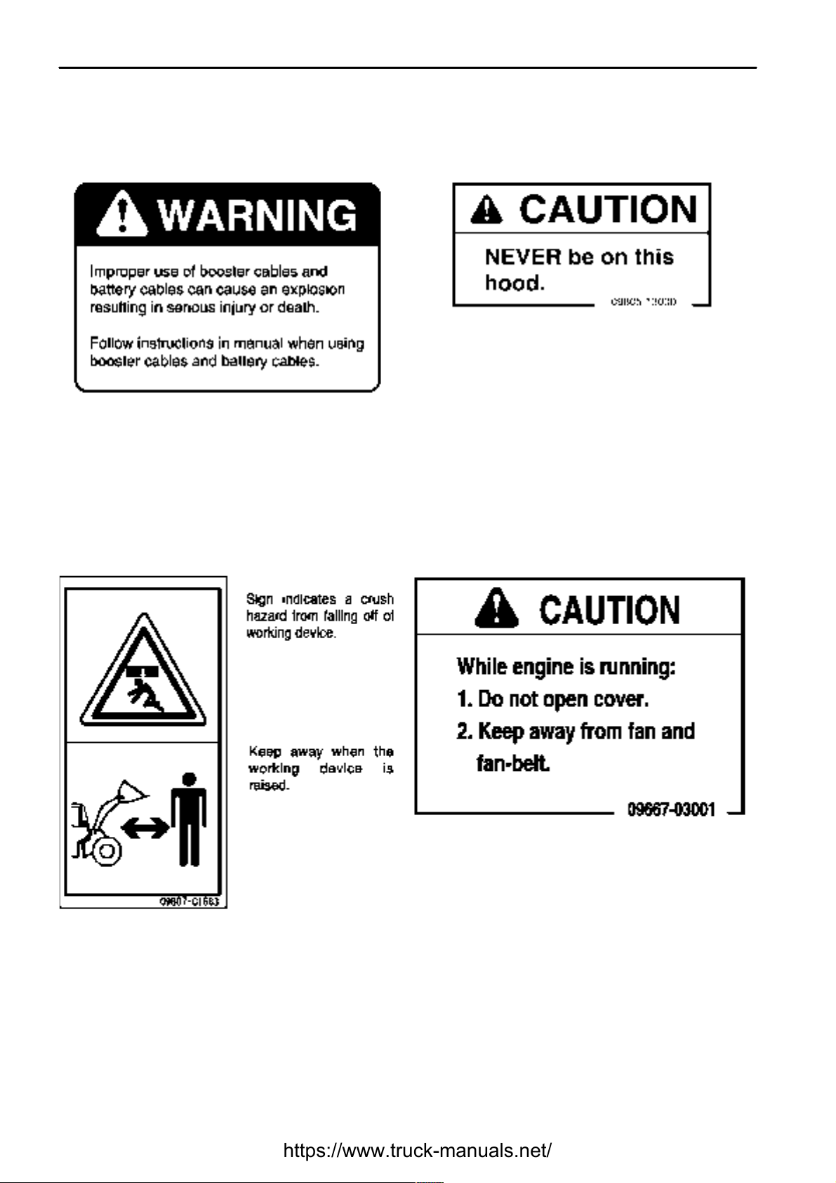
(9) Precautions when handling battery cable (10) Precautions to prohibit going up on the hood
(09805-13000)
(11) Do not go under work equipment sign
(09807-C1683)
(12) Do not open when engine is running sign
(09667-03001)
Page 22
.
SAFETY
SAFETY LABELS
2 - 9
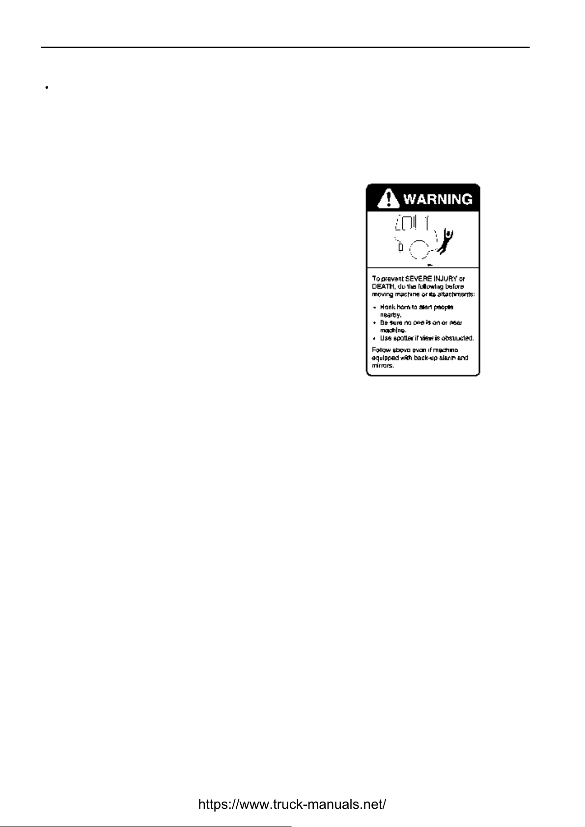
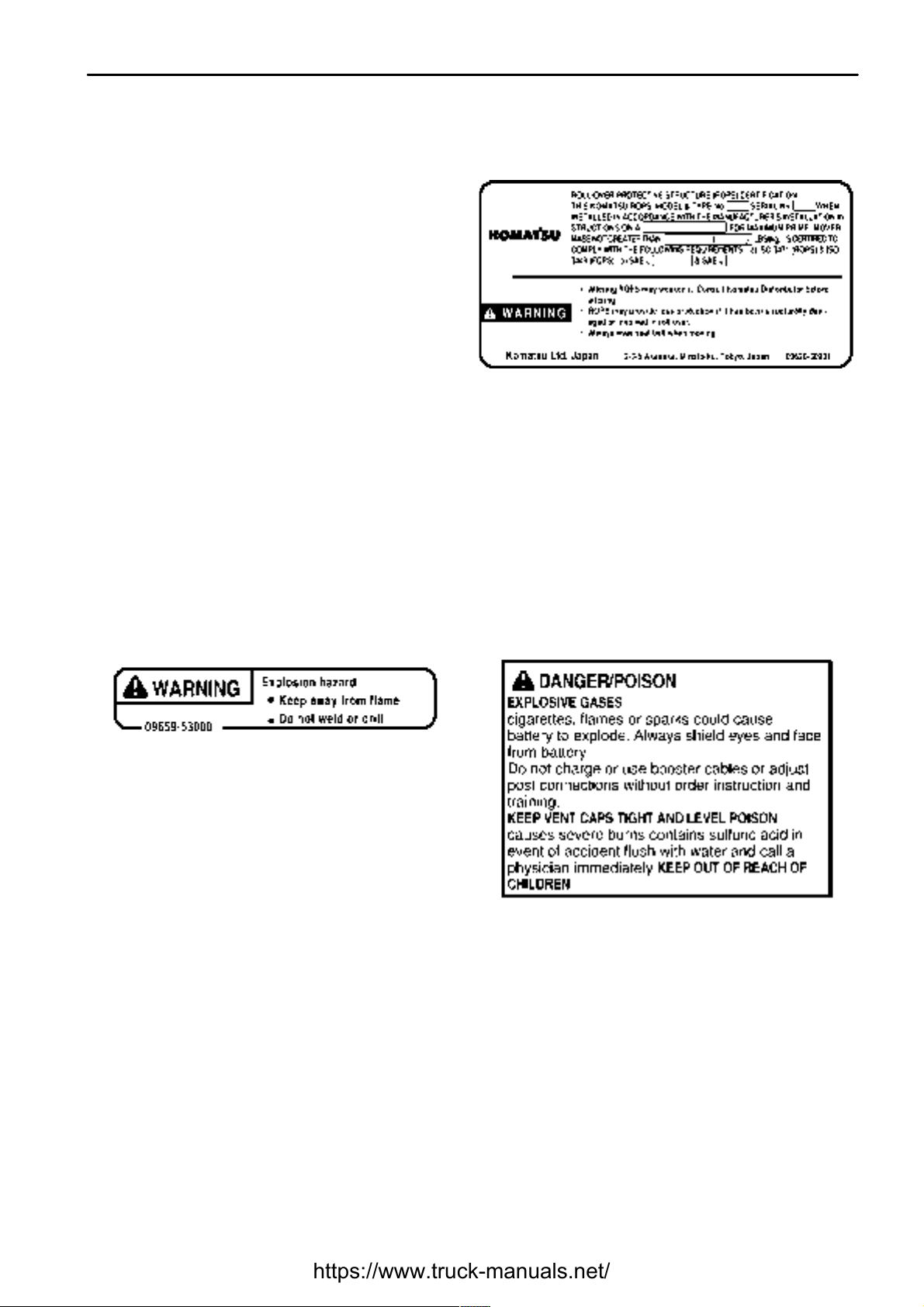
(13) Do not come near machine sign (09812-03000) (14) Do not modify ROPS sign (09620-30201)
(15) High pressure warning
(Precautions when handling accumulator)
(09659-53000)
(16) Precautions when handling battery
(09664-30000)
Page 23
.
SAFETY
SAFETY LABELS
2 - 10
(17) Precautions when handling battery
(This plate is stick on the machine by the battery
maker.)
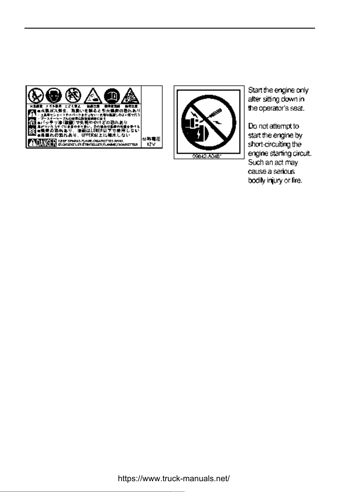
(18) Prohibition of jump start (09842-A0481)
Parts numbers for the safety labels (1), (3), (6): 41E-93-21160.
Parts numbers for the safety labels (4), (5), (7) to (9): 421-93-21311.
Page 24
.
SAFETY
GENERAL PRECAUTIONS
GENERAL PRECAUTIONS
SAFETY RULES
IF ABNORMALITIES ARE FOUND
CLOTHING AND PERSONAL PROTECTIVE ITEMS
FIRE EXTINGUISHER AND FIRST AID KIT
SAFETY FEATURES
2 - 11
Only trained and authorized personnel can operate and maintain the machine.
Follow all safety rules, precautions and instructions when operating or performing maintenance on the machine.
If you are under the influence of alcohol or medication, your ability to safely operate or repair your machine may
be severly impaired putting yourself and everyone else on your jobsite in danger.
When working with another operator or with a person on worksite traffic duty, be sure that all personnel
understand all hand signals that are to be used.
If you find any abnormality in the machine during operation or maintenance (noise, vibration, smell, incorrect
gauges, smoke, oil leakage, etc., or any abnormal display on the warning devices or monitor), report to the person
in charge and have the necessary action taken. Do not operate the machine until the abnormality has been
corrected.
Do not wear loose clothing and accessories. There is a hazard that they may catch on control levers or other
protruding parts.
If you have long hair and it hangs out from your hard hat, there
is a hazard that it may get caught up in the machine, so tie your
hair up and be careful not to let it get caught.
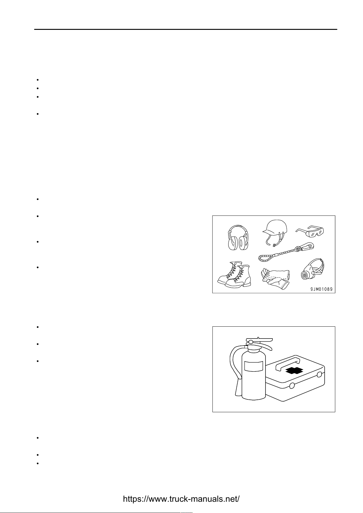
Always wear a hard hat and safety shoes. If the nature of the
work requires it, wear safety glasses, mask, gloves, ear plugs,
and safety belt when operating or maintaining the machine.
Check that all protective equipment functions properly before
using it.
Always follow the precautions below to prepare for action if any injury or fire should occur.
Be sure that fire extinguishers have been provided and read the
labels to ensure that you know how to use them in emergencies.
Carry out periodic inspection and maintenance to ensure that
the fire extinguisher can always be used.
Provide a first aid kit at the storage point. Carry out periodic
checks and add to the contents if necessary.
Be sure that all guards and covers are in their proper position. Have guards and covers repaired immediately if
they are damaged.
Understand the method of use of safety features and use them properly.
Never remove any safety features. Always keep them in good operating condition.
Page 25
.
SAFETY
GENERAL PRECAUTIONS
KEEP MACHINE CLEAN
INSIDE OPERATOR'S COMPARTMENT
ALWAYS APPLY LOCK WHEN LEAVING OPERATOR'S SEAT
2 - 12
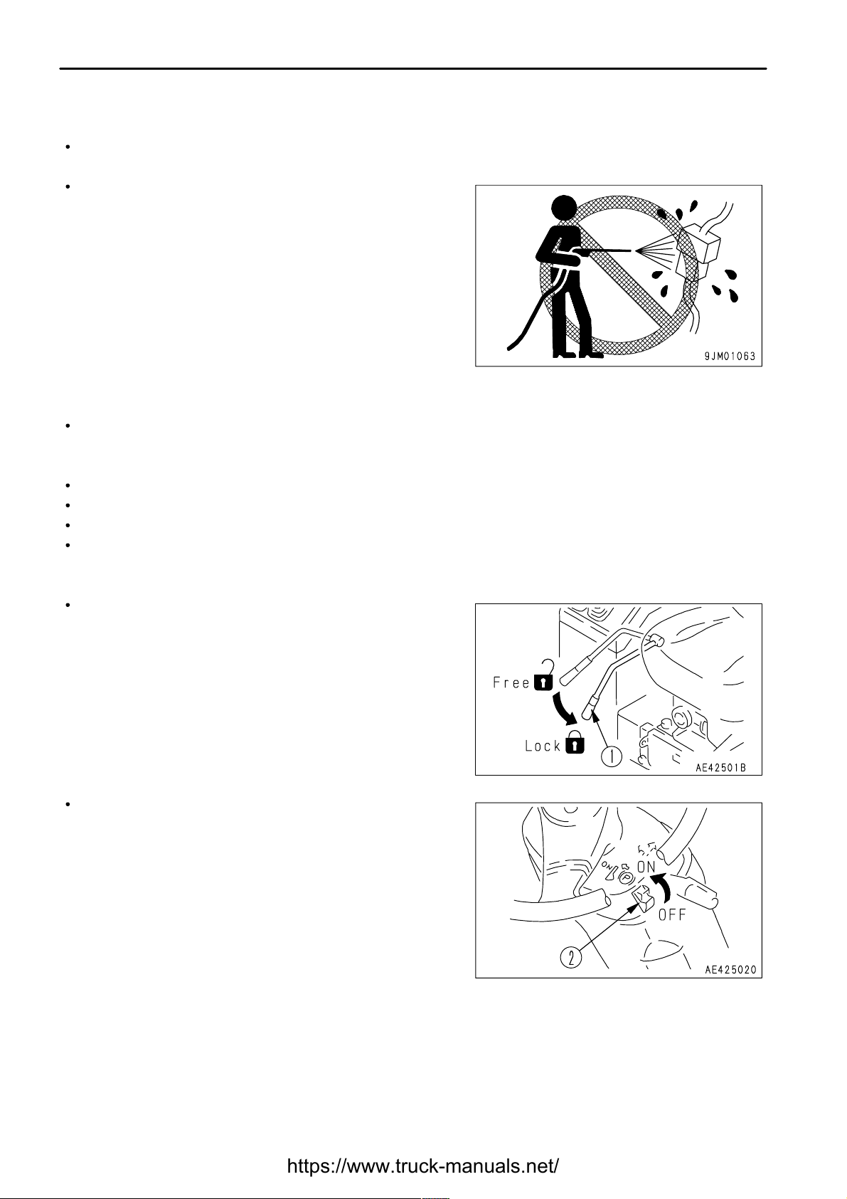
If water gets into the electrical system, there is a hazard that it will cause malfunctions or misoperation. Do not
use water or steam to wash the electrical system (sensors, connectors).
If inspection and maintenance is carried out when the machine
is still dirty with mud or oil, there is a hazard that you will slip and
fall, or that dirt or mud will get into your eyes. Always keep the
machine clean.
When entering the operator's compartment, always remove all mud and oil from the soles of your shoes.
If you operate the pedal with mud or oil affixed to your shoes, your foot may slip and this may cause a serious
accident.
Do not place parts and tools around the operator's seat.
Do not stick suction pads to the window glass. Suction pads act as a lens and may cause fire.
Do not use cellular telephones inside the operator's compartment when driving or operating the machine.
Never bring any dangerous objects such as flammable or explosive items into the operator's compartment.
Before standing up from the operator's seat to adjust the
operator's seat, always lower the work equipment, set safety
lock lever (1) to the LOCK position and parking brake switch (2)
to the ON position, then stop the engine.
If you accidentally touch the travel or swing lever when they are
not locked. The work equipment may suddenly move and cause
serious injury.
When leaving the machine, always lower the work equipment to
the ground, set safety lock lever (1) to the LOCK position and
parking brake switch (2) to the ON position, then stop the
engine. Lock all places and always take the key with you and
leave it in the specified location.
Page 26
.
SAFETY
GENERAL PRECAUTIONS
HANDRAILS AND STEPS
MOUNTING AND DISMOUNTING
NO PEOPLE ON ATTACHMENTS
2 - 13
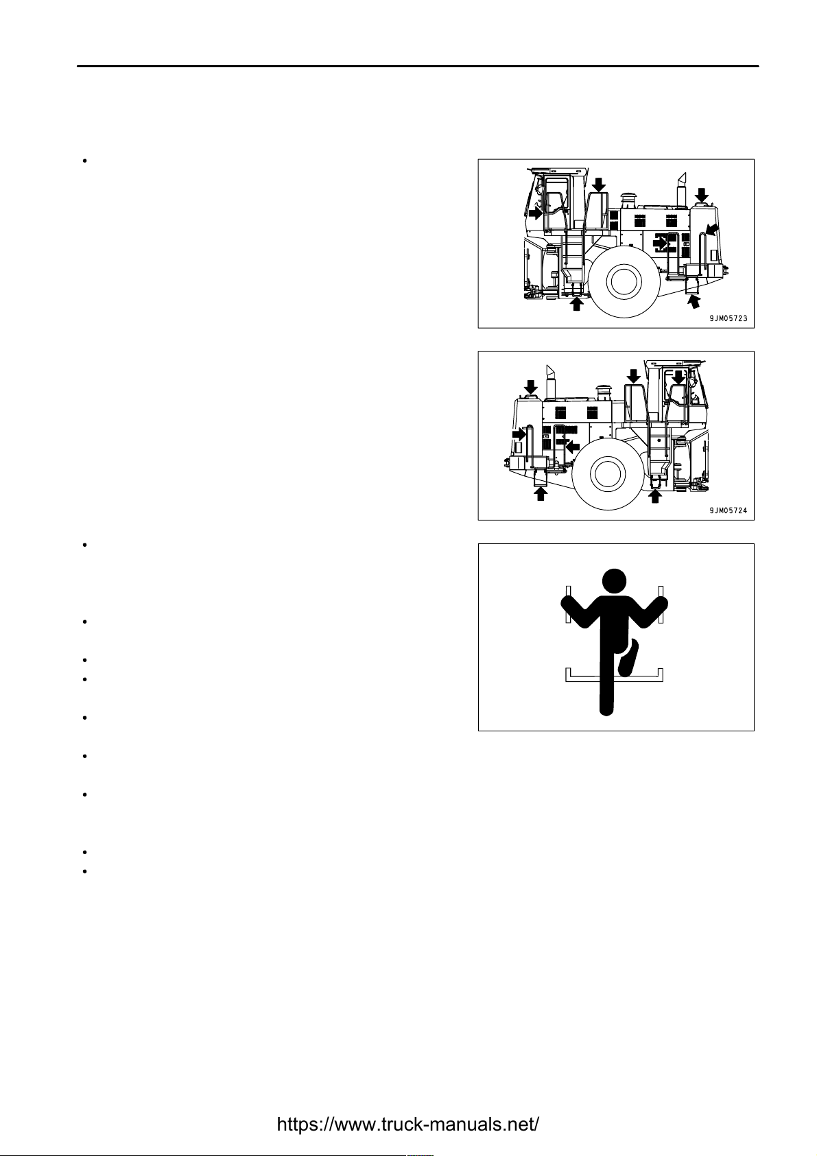
To prevent personal injury caused by slipping or falling off the machine, always do as follows.
Use the handrails and steps marked by arrows in the diagram on
the right when getting on or off the machine.
To ensure safety, always face the machine and maintain
three-point contact (both feet and one hand, or both hands and
one foot) with the handrails and steps to ensure that you support
yourself.
When entering the cab, stand on the top step before opening the
door.
Do not grip the control levers when getting on or off the machine.
Never climb on the engine hood or covers where there are no
non-slip pads.
Never move from the step at the rear of the machine or the step
at the side of the cab to stand on top of the tire.
Before getting on or off the machine, check the handrails and steps, and if there is any oil, grease, or mud on
them, wipe it off immediately. In addition, repair any damage and tighten any loose bolts.
Do not get on or off the machine while holding tools in your hand.
Never jump on or off the machine. Never get on or off a moving machine.
If the machine starts to move when there is no operator on the machine, do not jump on to the machine and try
to stop it.
Never let anyone ride on the work equipment, or other attachments. There is ahazard of falling and suffering serious
injury.
Page 27
.
SAFETY
GENERAL PRECAUTIONS
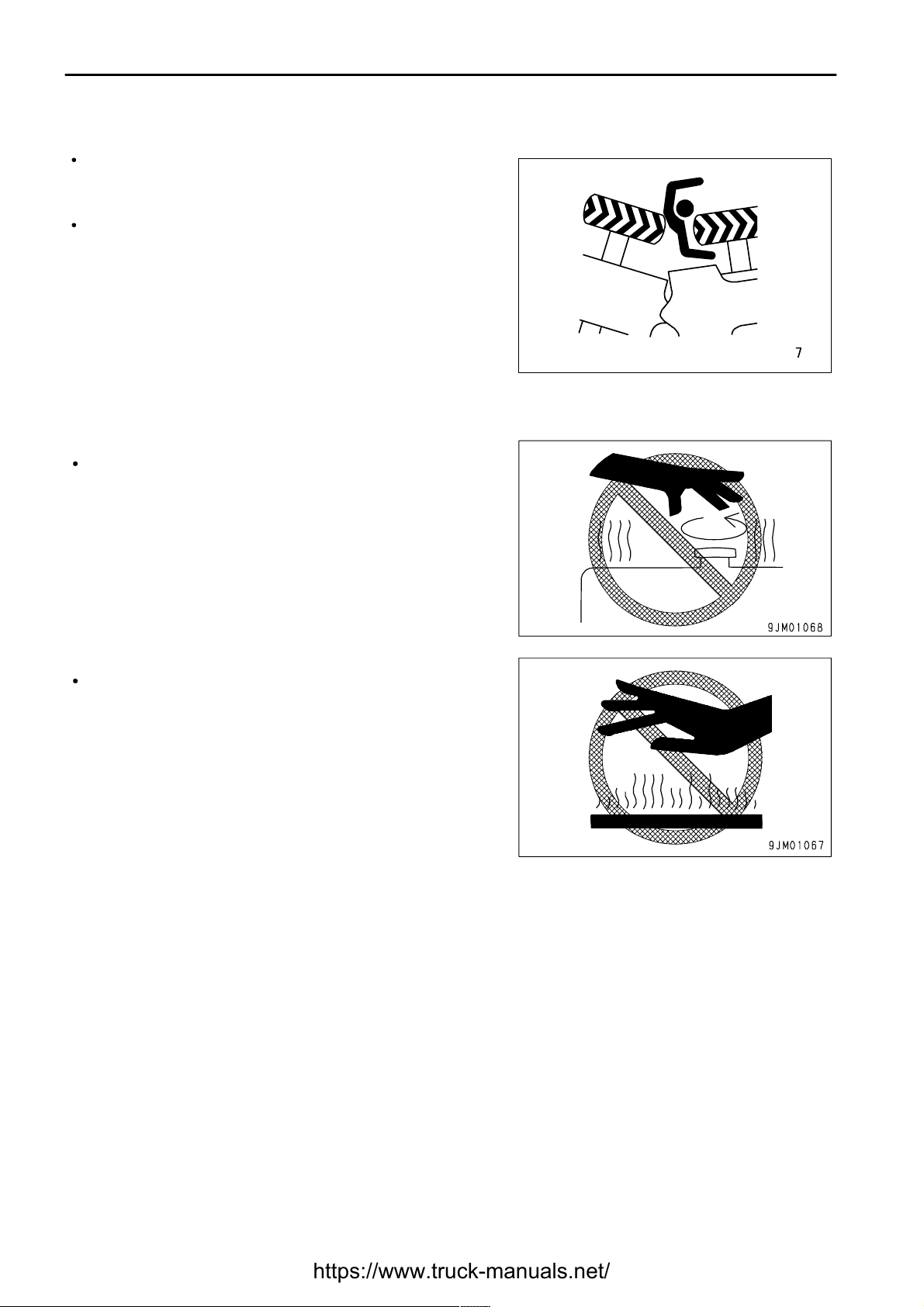
DO NOT GET CAUGHT IN ARTICULATED PORTION
PREVENTION OF BURNS
Hot
coolant
Hot
oil
2 - 14
If the clearance at the articulating portion changes, it will lead to
serious personal injury.
Do not allow anyone to come inside the articulation range.
The clearance in the area around the work equipment changes
according to the movement of the link. If you get caught, it will
lead to serious injury. Do not allow anyone near any of the
rotating or telescoping parts.
To prevent burns from hot water or steam spurting out when
checking or draining the coolant, wait for the water to cool to a
temperature where it is possible to touch the radiator cap by
hand before starting the operation. Even when the coolant has
cooled down, loosen the cap slowly to relieve the pressure
inside the radiator before removing the cap.
To prevent burns from hot oil spurting out when checking or
draining the oil, wait for the oil to cool to at temperature where
it is possible to touch the cap or plug by hand before starting the
operation. Even when the oil has cooled down, loosen the cap
or plug slowly to relieve the internal pressure before removing
the cap or plug.
Page 28
.
SAFETY
GENERAL PRECAUTIONS
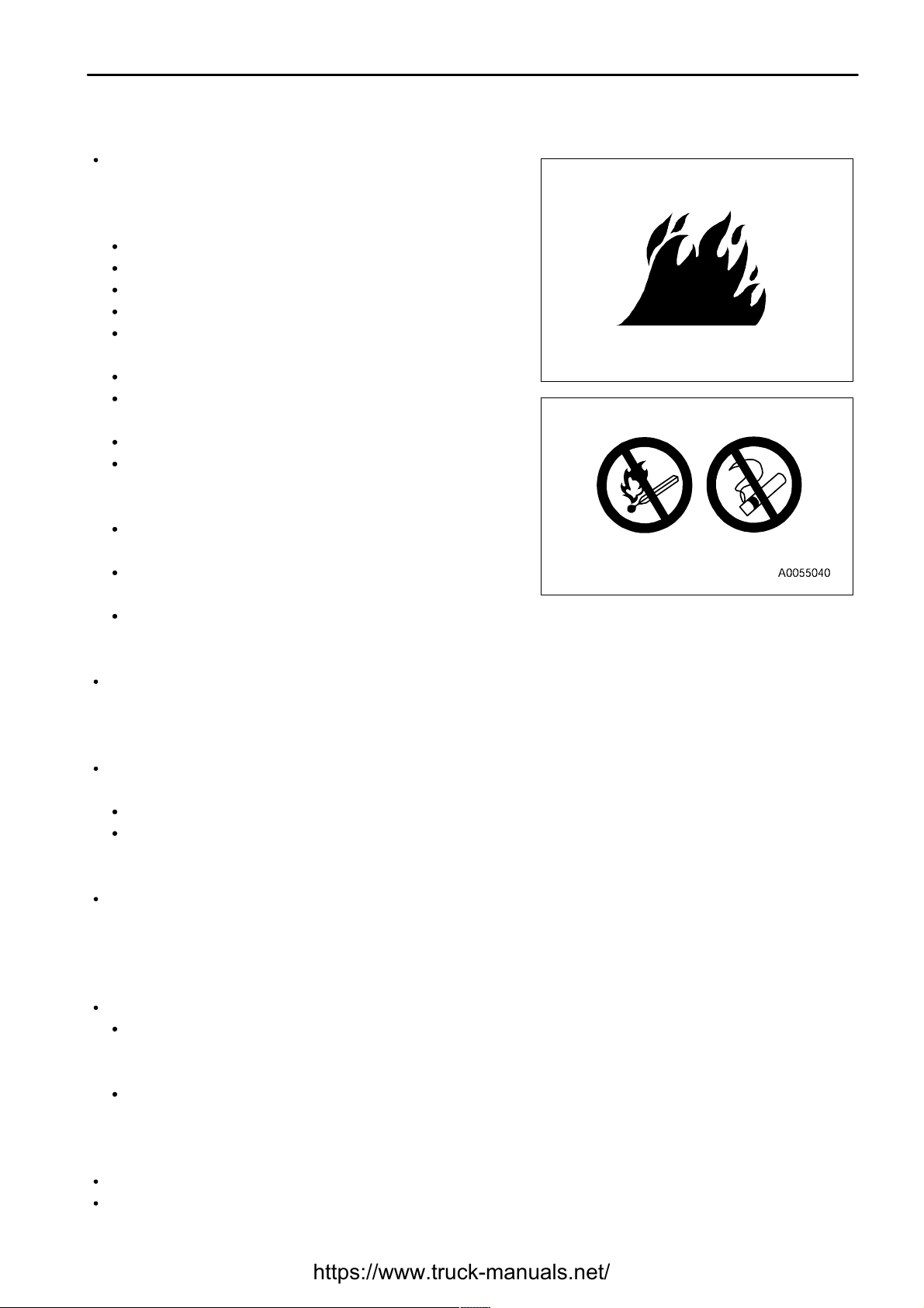
FIRE PREVENTION
Fire
caused
by
fueloroil
Fire
caused
by
accumulation
of
flammable
material.
Fire
coming
from
electric
wiring
Fire
coming
from
hydraulic
line
Explosion
caused
by
lighting
equipment
ACTION IF FIRE OCCURS
2 - 15
Fuel, oil, antifreeze, and window washer liquid are particularly
flammable and can be hazardous. To prevent fire, always
observe the following:
Do not smoke or use any flame near fuel or oil.
Stop the engine before refueling.
Do not leave the machine while adding fuel or oil.
Tighten all fuel and oil caps securely.
Do not spill fuel on overheated surfaces or on parts of the
electrical system.
Use well-ventilated areas for adding or storing oil and fuel.
Keep oil and fuel in the determined place and do not allow
unauthorized persons to enter.
After adding fuel or oil, wipe up any spilled fuel or oil.
When carrying out grinding or welding work on the chassis,
move any flammable materials to a safe place before
starting.
When washing parts with oil, use a non-flammable oil. Diesel
oil and gasoline may catch fire, so do not use them.
Put greasy rags and other flammable materials into a safe
container to maintain safety at the work place.
Do not weld or use a cutting torch to cut any pipes or tubes
that contain flammable liquids.
Remove any dry leaves, chips, pieces of paper, dust, or any other flammable materials accumulated or affixed
around the engine, exhaust manifold, muffler, or battery, or inside the undercovers.
Short circuits in the electrical system can cause fire.
Always keep electric wiring connections clean and securely tightened.
Check the wiring every day for looseness or damage. Tighten any loose connectors or wiring clamps. Repair
or replace any damaged wiring.
Check that all the hose and tube clamps, guards, and cushions are securely fixed in position.
If they are loose, they may vibrate during operation and rub against other parts. This may lead to damage to the
hoses, and cause high-pressure oil to spurt out, leading to fire damage or serious injury.
When checking fuel, oil, battery electrolyte, window washer fluid, or coolant, always use lighting with
anti-explosion specifications. If such lighting equipment is not used, there is danger of explosion that may
cause serious injury.
When taking the electrical power for the lighting from the machine itself, follow the instructions in this manual.
If a fire occurs, escape from the machine as follows.
Turn the start switch OFF to stop the engine.
Use the handrails and steps to get off the machine.
Page 29
.
SAFETY
GENERAL PRECAUTIONS
WINDOW WASHER LIQUID
PRECAUTIONS WHEN USING ROPS (Roll Over Protective Structure)
PRECAUTIONS FOR ATTACHMENTS
UNAUTHORIZED MODIFICATION
SAFETY AT WORKSITE
2 - 16
Use an ethyl alcohol base washer liquid.
Methyl alcohol base washer liquid may irritate your eyes, so do not use it.
Install ROPS when working in places where there is danger of
falling rocks, such as in mines and quarries, or in places where
there is danger of rolling over.
If ROPS is installed, do not remove it when operating the
machine.
ROPS is for protecting the operator when the machine is rolled
over. It bears the load when the machine is rolled over and it
absorbs the shock energy as well.
If the ROPS needs repair, or is altered, its strength can
decrease. Consult with your Komatsu distributor when and if
alteration or repair are necessary.
If ROPS is damaged or deformed by falling objects or by rolling
over, its strength will be reduced and it will not be able to fulfill
its function properly. In such cases, always Komatsu contact
your distributor for advice of the method of repair.
Even if ROPS is installed, always fasten your seat belt properly
when operating the machine. If you do not use your fasten your
seat belt properly, it cannot display its effect.
When installing optional parts or attachments, there may be problems with safety or legal restrictions. Therefore
contact your Komatsu distributor for advice.
Any injuries, accidents, or product failures resulting from the use of unauthorized attachments or parts will not be
the responsibility of Komatsu.
When installing and using optional attachments, read the instruction manual for the attachment, and the general
information related to attachments in this manual.
Any modification made without authorization from Komatsu can create hazards. Before making a modification,
consult your Komatsu distributor.
Komatsu will not be responsible for any injuries, accidents, product failures or other property damages resulting
from modifications made without authorization from Komatsu.
Before starting operations, thoroughly check the area for any unusual conditions that could be dangerous.
When carrying out operations near combustible materials such as thatched roofs, dry leaves or dry grass, there
is a hazard of fire, so be careful when operating.
Check the terrain and condition of the ground at the worksite, and determine the safest method of operation. Do
not carry out operations at places where there is a hazard of landslides or falling rocks.
Page 30
.
SAFETY
GENERAL PRECAUTIONS
SAFETY
GENERAL PRECAUTIONS
WORKING ON LOOSE GROUND
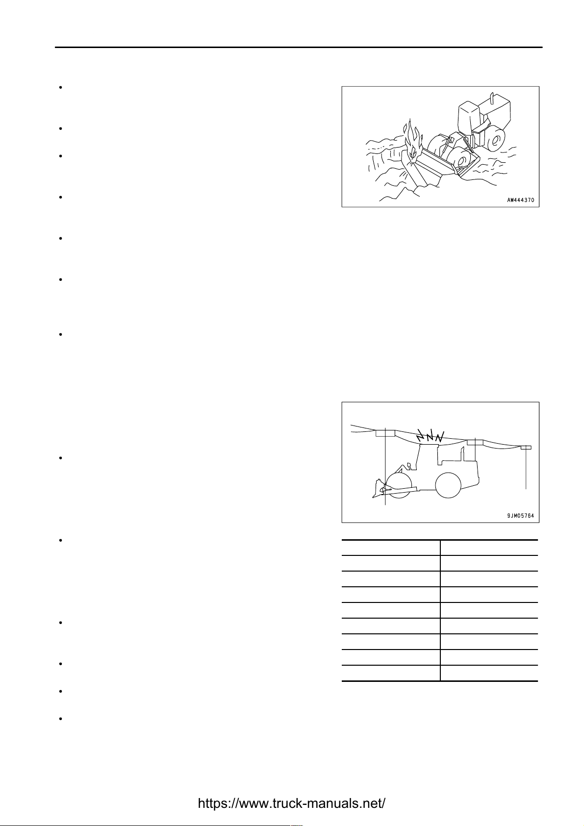
DO NOT GO CLOSE TO HIGH-VOLTAGE CABLES
2 - 17
If water lines, gas lines, or high-voltage electrical lines may be
buried under the worksite, contact each utility and identify their
locations. Be careful not to sever or damage any of these lines.
Take necessary measures to prevent any unauthorized person
from entering the operating area.
In particular, if you need to operate on a road, protect pedestrian
and cars by designating a person for worksite traffic duty or by
installing fences around the worksite.
When traveling or operating in shallow water or on soft ground,
check the shape and condition of the bedrock, and the depth
and speed of flow of the water before starting operations.
In order that travel operations can be carried out safely, always keep the roads on the jobsite properly maintained.
Avoid traveling or operating your machine too close to the edge of cliffs, overhangs, and deep ditches. The
ground may be weak in such areas. If the ground should collapse under the weight or vibration of the machine,
there is a hazard that the machine may fall or tip over. Remember that the soil after heavy rain or blasting or after
earthquakes is weak in these areas.
When working on embankments or near excavated ditches, there is a hazard that the weight and vibration of the
machine will cause the soil to collapse. Before starting operations, take steps to ensure that the ground is safe
and to prevent the machine from rolling over or falling.
Do not travel or operate the machine near electric cables. There is
a hazard of electric shock, which may cause serious injury or
property damage. On jobsites where the machine may go close to
electric cables, always do as follows.
Before starting work near electric cables, inform the local power
company of the work to be performed, and ask them to take the
necessary action.
Even going close to high-voltage cables can cause electric
shock, which may cause serious burns or even death. Always
maintain a safe distance (see the table on the right) between the
machine and the electric cable. Check with the local power
company about safe operating procedure before starting
operations.
To prepare for any possible emergencies, wear rubber shoes
and gloves. Lay a rubber sheet on top of the seat, and be careful
not to touch the chassis with any exposed part of your body.
Use a signalman to give warning if the machine approaches too
close to the electric cables.
When carrying out operations near high voltage cables, do not
let anyone come close to the machine.
If the machine should come too close or touch the electric cable, to prevent electric shock, the operator should
not leave the operator's compartment until it has been confirmed that the electricity has been shut off.
Also, do not let anyone come close to the machine.
Voltage of Cables Safety Distance
100 V - 200 V Over 2 m (7ft)
6,600 V Over 2 m (7ft)
22,000 V Over 3 m (10 ft)
66,000 V Over 4 m (14 ft)
154,000 V Over 5 m (17 ft)
187,000 V Over 6 m (20 ft)
275,000 V Over 7 m (23 ft)
500,000 V Over 11 m (36 ft)
Page 31

.
SAFETY
GENERAL PRECAUTIONS
ENSURE GOOD VISIBILITY
PRECAUTIONS RELATED TO VENTILATION EXHAUST GAS
CHECKING SIGNALMAN'S SIGNALS AND SIGNS
EMERGENCY EXIT FROM OPERATOR'S CAB
VENTILATION FOR ENCLOSED AREAS
2 - 18
Check for any persons or obstacles in the area around the machine and check the conditions of the jobsite to
ensure that operations and travel can be carried out safely. Always do as follows.
Position a signalman if there are areas at the rear of the machine where the visibility is not good.
When working in dark places, turn on the working lamp and front lamps installed to the machine, and set up
additional lighting in the work area if necessary.
Stop operations if the visibility is poor, such as in mist, snow, rain, or dust.
Engine exhaust gas includes substances that may harm your
health or even kill. Always select a place with good ventilation
when starting the engine or operating the machine.
If it is necessary to start the engine or run the machine inside a
building or underground, where the ventilation is poor, take steps
to remove the exhaust gas and bring in ample fresh air.
Set up signs to inform of road shoulders and soft ground. If the visibility is not good, position a signalman if
necessary. Operators should pay careful attention to the signs and follow the instructions from the signalman.
Only one signalman should give signals.
Make sure that all workers understand the meaning of all signals and signs before starting work.
Machines equipped with a cab have doors on the left and right sides. If the door on the one side does not open,
escape from the door on the other side.
Asbestos dust in the air can cause lung cancer if it is inhaled. There
is danger of inhaling asbestos when working on jobsites handling
demolition work or work handling industrial waste. Always observe
the following.
Spray water to keep down the dust when cleaning. Do not use
compressed air for cleaning.
If there is danger that there may be asbestos dust in the air,
always operate the machine from an upwind position. All
workers should use an approved respirator.
Do not allow other persons to approach during the operation.
Always observe the rules and regulations for the work site and environmental standards.
This machine does not use asbestos, but there is a danger that imitation parts may contain asbestos, so always use
genuine Komatsu parts.
Page 32

.
SAFETY
PRECAUTIONS FOR OPERATION
PRECAUTIONS FOR OPERATION
STARTING ENGINE
CHECKS BEFORE STARTING ENGINE
PRECAUTIONS WHEN STARTING
2 - 19
If there is a warning tag hanging from the blade control lever, do not
start the engine or touch the levers (1).
Carry out the following checks before starting the engine at the beginning of the day's work.
Remove all dirt from the surface of the window glass to ensure a good view.
Remove all dirt from the surface of the lens of the front lamps, working lamps, and rear combination lamp, and
check that they light up correctly.
Check the coolant level, fuel level, and oil level in engine oil pan, check for clogging of the air cleaner, and check
for damage to the electric wiring.
Check that there is no mud or dust accumulated around the movable parts of the accelerator pedal or brake pedal,
and check that the pedals work properly.
Adjust the operator's seat to a position where it is easy to carry out operations, and check that there is no damage
or wear to the seat belt or mounting clamps.
Check that the gauges work properly, check the angle of the lights and working lamps, and check that the control
levers are all at the neutral position.
Before starting the engine, make sure that the safety lock lever is in the LOCK position.
Adjust the mirrors so that the rear of the machine can be seen clearly from the operator's seat. See "ADJUST
REAR VIEW MIRROR (PAGE 3-50)".
Check that there are no persons or obstacles above, below, or in the area around the machine.
When starting the engine, sound the horn as a warning.
Start and operate the machine only while seated.
Do not allow anyone apart from the operator to ride on the machine.
Do not short circuit the starting motor circuit to start the engine. Short circuit can cause fire.
For machines equipped with a back-up alarm, check that the alarm works properly.
Page 33

.
SAFETY
PRECAUTIONS FOR OPERATION
PRECAUTIONS IN COLD AREAS
2 - 20
Carry out the warming-up operation thoroughly. If the machine is not thoroughly warmed up before the control
levers are operated, the reaction of the machine will be slow, and this may lead to unexpected accidents.
If the battery electrolyte is frozen, do not charge the battery or start the engine with a different power source.
There is a hazard that this will ignite the battery.
Before charging or starting the engine with a different power source, melt the battery electrolyte and check for
frost and leakage of battery electrolyte before starting.
Page 34

.
SAFETY
PRECAUTIONS FOR OPERATION
OPERATION
CHECKS BEFORE OPERATION
PRECAUTIONS WHEN TRAVELING IN FORWARD OR REVERSE
2 - 21
When carrying out the checks, move the machine to a wide area where there are no obstructions, and operate
slowly. Do not allow anyone near the machine.
Always fasten your seat belt.
Check the operation of travel, steering and brake systems, and
work equipment control system.
Check for any abnormality in the sound of the machine,
vibration, heat, smell, or gauges; check also that there is no
leakage of oil or fuel.
If any abnormality is found, carry out repairs immediately.
Before driving the machine or starting operations, check that
safety bar (1) is securely fixed at the FREE position.
Before travelling, check again that there is no one in the surrounding area, and that there are no obstacles.
Before travelling, sound the horn to warn people in the area.
Always operate the machine only when seated.
Do not allow anyone apart from the operator to ride on the machine.
Check that the back-up alarm (alarm buzzer when machine travels in reverse) works properly.
Always lock the door and windows of the operator's compartment in position (open or closed).
On jobsites where there is a hazard of flying objects or of objects entering the operator's compartment, check that
the door and windows are securely closed.
If there is an area to the rear of the machine which cannot be
seen, position a signal person. Take special care not to hit other
machines or people when turning or swinging the machine.
Always be sure to carry out the above precautions even when the
machine is equipped with mirrors.
Page 35

.
SAFETY
PRECAUTIONS FOR OPERATION
PRECAUTIONS WHEN TRAVELING
2 - 22
Never turn the key in the starting switch to the OFF position. It is dangerous if the engine stops when the machine
is traveling, because the steering becomes heavy. If the engine stops, depress the brake pedal immediately to
stop the machine.
When traveling on level ground, keep the work equipment at
height "A" of 50 to 60 cm (20 to 24 in) from the ground. If the
work equipment control levers have to be operated, stop the
machine first, then operate the levers.
When traveling on rough ground, travel at low speed and do not
operate the steering suddenly. There is danger that the machine
may turn over. The work equipment may hit the ground surface
and cause the machine to lose its balance, or may damage the
machine or structures in the area.
Avoid traveling over obstacles when possible. If the machine
has to travel over an obstacle, keep the work equipment close
to the ground and travel at low speed. Never travel over
obstacles which make the machine tilt strongly to one side.
When traveling or carrying out operations, always keep a safe distance from people, structures, or other
machines to avoid coming into contact with them.
When passing over bridges or structures, check first that the structure is strong enough to support the mass of
the machine.
When operating in tunnels, under bridges, under electric wires, or other places where the height is limited, operate
slowly and be extremely careful not to let the work equipment hit anything.
Always obey the traffic regulations when traveling on public roads. This machine travels at a lower speed than
normal automobiles, so keep to the side of the road and be careful to leave the center of the road free for other
vehicles.
If you drive the machine at high speed continuously for a long time, the tires will overheat and the internal pressure
will become abnormally high. This may cause the tires to burst. If a tire bursts, it produces an extremely large
destructive force, and this may cause serious injury or accident.
If you are going to travel continuously, please consult your Komatsu distributor.
Page 36

.
SAFETY
PRECAUTIONS FOR OPERATION
TRAVELING ON SLOPES
PROHIBITED OPERATIONS
2 - 23
To prevent the machine from tipping over or slipping to the side,
always do as follows.
When traveling on slopes, keep the work equipment at height
"A" of approximately 50 to 60 cm (20 to 24 in) above the ground.
In case of emergency, quickly lower the work equipment to the
ground to help the machine to stop.
Always travel straight up or down a slope. Traveling at an angle
or across the slope is extremely dangerous.
Do not turn on slopes or travel across slopes. Always go down
to a flat place to change the position of the machine, then travel
on to the slope again.
Travel on grass, fallen leaves, or wet steel plates with low speed. Even with slight slopes there is a hazard that
the machine may slip.
If the engine stops, depress the brake pedal immediately, lower the blade to the ground, and apply the parking
brake to stop the machine.
When traveling downhill, never shift gear or place the transmission at neutral. It is dangerous not to use the
braking force of the engine. Always place the transmission in a low gear before starting to travel downhill.
When traveling downhill, travel slowly. If necessary, use the braking force of the engine together with the brake
pedal to control the travel speed.
It is dangerous to use the blade for crane operations, so do not carry out such operations.
Page 37

.
SAFETY
PRECAUTIONS FOR OPERATION
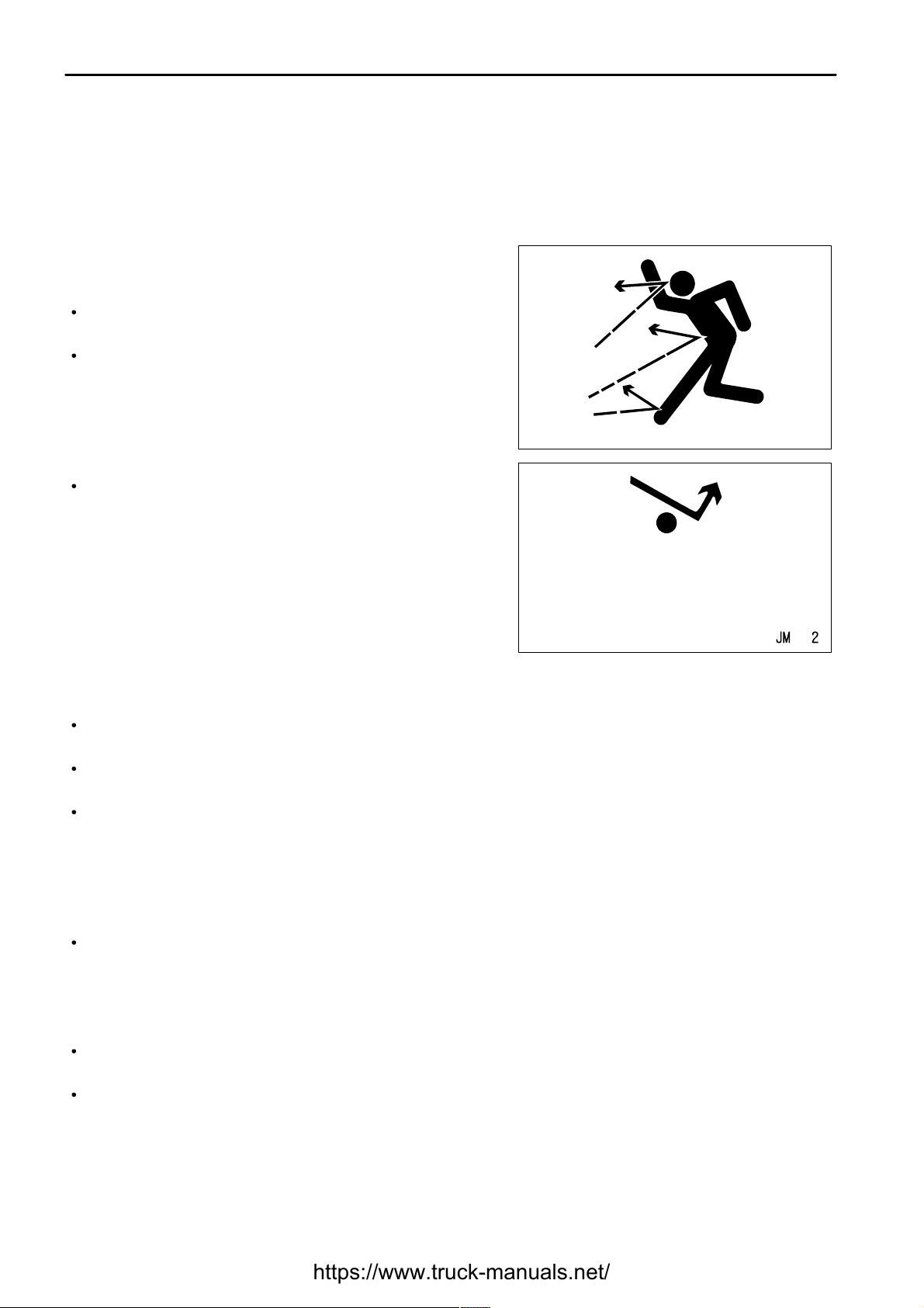
PRECAUTIONS WHEN OPERATING
METHODS OF USING BRAKE
OPERATE CAREFULLY ON SNOW
2 - 24
When using the machine, to prevent accidents resulting from damage to the work equipment caused by
overloading, do not exceed the maximum permitted load or performance determined by the structure of the
machine.
If the engine cannot be started again after it has stopped, immediately operate the work equipment control levers
to lower the work equipment to the ground. (After the engine stops, the accumulator allows the work equipment
to be operated for a limited time.)
Be careful not to approach too close to the edge of cliffs. When making embankments or landfills, or when
dropping soil over a cliff, dump one pile, then use the next pile of soil to push the first pile.
The load suddenly becomes lighter when the soil is pushed over a cliff or when the machine reaches the top of
a slope. When this happens, there is danger that the travel speed will suddenly increase, so be sure to reduce
the speed.
When operating in tunnels, under bridges, under electric wires,
or when entering buildings, or operating in other places where
the height is limited, be extremely careful not to let the cab hit
anything.
To prevent accidents caused by hitting other objects, always
operate the machine at a speed which is safe for operation,
particular in confined spaces, indoors, and in places where there
are other machines.
When the machine is traveling, do not rest your foot on the brake pedal. If you travel with your foot resting on the
pedal, the brake will always be applied, and this will cause the brakes to overheat and fail.
Do not depress the brake pedal repeatedly if not necessary.
When traveling downhill, use the braking force of the engine, and always use the right brake pedal at the same
time.
Snow-covered or frozen surfaces are slippery, so be extremely careful when traveling or operating the machine,
and do not operate the levers suddenly. Even a slight slope may cause the machine to slip, so be particularly
careful when working on slopes.
With frozen ground surfaces, the ground becomes soft when the temperature rises, and this may cause the
machine to tip over.
If the machine enters deep snow, there is a hazard that it may tip over or become buried in the snow. Be careful
not to leave the road shoulder or to get trapped in a snow drift.
When clearing snow, the road shoulder and objects placed beside the road are buried in the snow and cannot be
seen. There is a hazard of the machine tipping over or hitting covered objects, so always carry out operations
carefully.
When traveling on snow-covered roads, always fit tire chains.
When traveling on snow-covered slopes, never apply the foot brake suddenly. Reduce the speed and use the
engine as a brake while applying the foot brake intermittently (depress the brake intermittently several times). If
necessary, lower the blade to the ground to stop the machine.
Page 38

.
SAFETY
PRECAUTIONS FOR OPERATION
PARKING MACHINE
2 - 25
Park the machine on firm, level ground.
Select a place where there is no hazard of falling rocks or
landslides, or of flooding if the land is low.
Lower the work equipment completely to the ground.
When leaving the machine, set safety lock lever (1) to the LOCK
position and parking brake switch (2) to the ON position, and
stop the engine.
Always close the operator's cab door, and use the key to lock all
the equipment in order to prevent any unauthorized person from
moving the machine. Always remove the key, take it with you,
and leave it in the specified place.
If it is necessary to park the machine on a slope, set blocks
under the wheels to prevent the machine from moving.
Page 39

.
SAFETY
PRECAUTIONS FOR OPERATION
TRANSPORTATION
LOADING AND UNLOADING
SHIPPING
2 - 26
The machine can be divided into parts for transportation, so when transportating the machine, please contact your
Komatsu distributor to have the work carried out.
When loading or unloading the machine, mistaken operation may
bring the hazard of the machine tipping over or falling, so particular
care is necessary. Always do as follows.
Perform loading and unloading on firm, level ground only.
Maintain a safe distance from the edge of the road or cliff.
Always use ramps of adequate strength. Be sure that the ramps
are wide, long, and thick enough to provide a safe loading slope.
Take suitable steps to prevent the ramps from moving out of
position or coming off.
Be sure the ramp surface is clean and free of grease, oil, ice and
loose materials. Remove dirt from machine-tracks. On a rainy
day, in particular, be extremely careful since the ramp surface is
slippery.
Run the engine at low speed and travel slowly.
Never correct your steering on the ramps. If necessary, drive off the ramps, correct the direction, then enter the
ramps again.
When loading or unloading to an embankment or platform, make sure that it has suitable width, strength, and
grade.
For machines equipped with a cab, always lock the door after boarding the machine. If this is not done, the door
may suddenly open during transportation.
Refer to "TRANSPORTATION (PAGE 3-72)".
When shipping the machine on a trailer, do as follows.
The weight, transportation height, and overall length of the machine differ according to the work equipment, so
be sure to confirm the dimensions.
When passing over bridges or structures on private land, check first that the structure is strong enough to support
the weight of the machine. When traveling on public roads, check first with the relevant authorities and follow their
instructions.
Lock the frame with the safety bar to prevent the machine from articulating.
For details of the shipping procedure, see "TRANSPORTATION (PAGE 3-72)" in the OPERATION section.
Page 40

.
SAFETY
PRECAUTIONS FOR OPERATION
BATTERY
BATTERY HAZARD PREVENTION
2 - 27
Battery electrolyte contains sulphuric acid, and batteries generate flammable hydrogen gas, which may explode.
Mistaken handling can lead to serious injury or fire. For this reason, always observe the following precautions.
Do not use or charge the battery if the battery electrolyte level is below the LOWER LEVEL line. This may cause
an explosion. Always check the battery electrolyte level periodically and add distilled water to bring the electrolyte
level to the UPPER LEVEL line.
When working with batteries, always wear safety glasses and rubber gloves.
Never smoke or use any flame near the battery.
If you spill acid on your clothes or skin, immediately flush the
area with large amount of water.
If acid gets into your eyes, flush them immediately with large
amount of water and seek medical attention.
Before working with batteries, turn the starting switch to the OFF position.
As there is a hazard that sparks will be generated, always do as follows.
Do not let tools or other metal objects make any contact between the battery terminals. Do not leave tools or other
metal objects lying around near the battery.
Always disconnect the negative (-) terminal (ground side) first when removing the battery; when installing the
battery, connect the positive (+) terminal first, and connect the ground last.
Attach the battery terminal securely.
Flammable hydrogen gas is generated when the battery is charged, so remove the battery from the chassis, take
it to a well-ventilated place, and remove the battery caps before charging it.
Tighten the battery caps securely.
Install the battery securely to the determined place.
Page 41

.
SAFETY
PRECAUTIONS FOR OPERATION
STARTING WITH BOOSTER CABLES
2 - 28
If any mistake is made in the method of connecting the booster
cables, it may cause the battery to explode, so always do as
follows.
When starting with a booster cable, carry out the starting
operation with two workers (one worker sitting in the operator's
seat and the other working with the battery).
When starting from another machine, do not allow the two
machines to touch.
When connecting the booster cables, turn the starting switch
OFF for both the normal machine and problem machine. There
is a hazard that the machine will move when the power is
connected.
Be sure to connect the positive (+) cable first when installing the
booster cables. Disconnect the negative (-) cable (ground side)
first when removing them.
When removing the booster cables, be careful not to let the
booster cable clips touch each other or to let the clips touch the
machine.
Always wear safety goggles and rubber gloves when starting
the engine with booster cables.
When connecting a normal machine to a problem machine with booster cables, always use a normal machine
with the same battery voltage as the problem machine.
For details of the starting procedure when using booster cables, see "STARTING ENGINE WITH BOOSTER
CABLE (PAGE 3-83)" in the OPERATION section.
Page 42

.
SAFETY
PRECAUTIONS FOR OPERATION
TOWING
2 - 29
Serious injury or death could result if a disabled machine is towed incorrectly or if there is a mistake in the selection
or inspection of the wire rope.
For towing, see "TOWING THE MACHINE (PAGE 3-79)".
Always wear leather gloves when handling wire rope.
During the towing operation, never stand between the towing
machine and the machine being towed.
Never tow a machine on a slope.
Never use a wire rope which has cut strands (A), reduced
diameter (B), or kinks (C). There is danger that the rope may
break during the towing operation.
Page 43

.
SAFETY
PRECAUTIONS FOR MAINTENANCE
PRECAUTIONS FOR MAINTENANCE
WARNING TAG
KEEP WORK PLACE CLEAN AND TIDY
APPOINT LEADER WHEN WORKING WITH OTHERS
MAINTENANCE WITH ENGINE RUNNING
2 - 30
Always attach the "DO NOT OPERATE" warning tag to blade
control lever (1) in the operator's cab to alert others that you are
performing service of maintenance on the machine. Attach
additional warning tags around the machine if necessary.
Warning tag Part No.09963-03001
Keep this warning tag in the tool box while it is not used. If there
is not the tool box, keep the tag in the operation manual pocket.
If others start the engine, or touch or operate the work equipment control lever while you are performing service
or maintenance, you could suffer serious injury or property damage.
Do not leave hammers or other tools lying around in the work place. Wipe up all grease, oil, or other substances
that will cause you to slip. Always keep the work place clean the tidy to enable you to carry out operations safely.
If the work place is not kept claen and tidy, there is the danger that you will trip, slip, or fall over and injure yourself.
When repairing the machine or when removing and installing the work equipment, appoint a leader and follow his
instructions during the operation.
When working with others, misunderstandings between workers can lead to serious accidents.
Stop the machine on firm, level ground.
Select a place where there is no hazard of falling rocks or
landslides, or of flooding if the land is low.
Lower the work equipment completely to the ground and stop
the engine.
Page 44

.
SAFETY
PRECAUTIONS FOR MAINTENANCE
SAFETY
PRECAUTIONS FOR MAINTENANCE
2 - 31
After stopping the engine, operate blade control lever (1) 2 to 3
times fully to the RAISE and LOWER positions to release the
pressure inside the hydraulic circuit, then set safety lock lever
(2) to the LOCK position.
Turn parking brake switch (3) to the ON position to apply the
parking brake, then put blocks under the front and rear of the
tires.
Lock the frame with safety bar (4) to prevent the machine from
articulating.
Page 45

.
SAFETY
PRECAUTIONS FOR MAINTENANCE
TWO WORKERS FOR MAINTENANCE WHEN ENGINE IS RUNNING
PROPER TOOLS
2 - 32
To prevent injury, do not carry out maintenance with the engine running. If maintenance must be carried out with
the engine running, carry out the operation with at least two workers and do as follows.
One worker must always sit in the operator's seat and be ready
to stop the engine at any time. All workers must maintain
contact with the other workers.
Never drop or insert tools or other objects into the fan or fan belt.
Parts may break or be sent flying.
When carrying out operations near the fan, fan belt, or other
rotating parts, there is a hazard of being caught in the parts, so
be careful not to come close.
Set safety lock lever (1) to the LOCK position to prevent the work
equipment from moving.
Turn parking brake switch (2) to the ON position to apply the
parking brake.
Do not touch any control levers. If any control lever must be
operated, give a signal to the other workers to warn them to
move to a safe place.
Use only tools suited to the task and be sure to use the tools
correctly. Using damaged, low quality, faulty, makeshift tools or
improper use of the tools could cause serious personal injury.
Page 46

.
SAFETY
PRECAUTIONS FOR MAINTENANCE
WORK EQUIPMENT SUPPORT
ACCUMULATOR
PERSONNEL
ATTACHMENTS
NOISE
2 - 33
When carrying out inspection and maintenance with the work
equipment raised, or if it is necessary to go under the machine,
use strong supports that can fully withstand the weight of the
machine or work equipment, and be sure to fix the stands in
position securely.
The accumulator is charged with high-pressure nitrogen gas.
When handling the accumulator, careless procedure may cause
an explosion which could lead to serious injury or property
damage. For this reason, always observe the following
precautions.
Do not disassemble the accumulator.
Do not bring it near flame or dispose of it in fire.
Do not make holes in it, weld it, or use a cutting torch.
Do not hit or roll the accumulator, or subject it to any impact.
When disposing of the accumulator, the gas must be released.
Please contact your Komatsu distributor to have this work
performed.
Only authorized personnel can service and repair the machine. Do not allow unauthorized personnel into the area.
If necessary, employ an observer.
Appoint a leader before starting removal or installation
operations for attachments.
Place attachments that have been removed from the machine in
a stable condition so that they do not fall. And take steps to
prevent unauthorized persons from entering the storage area.
If the noise from the machine is too loud, it may cause temporary or permanent hearing problems. When carrying
out maintenance of the engine and you are exposed to noise for long periods of time, wear ear covers or ear plugs
while working.
Page 47

.
SAFETY
PRECAUTIONS FOR MAINTENANCE
PRECAUTIONS WHEN USING HAMMER
REPAIR WELDING
REMOVING BATTERY TERMINAL
PRECAUTIONS WITH HIGH-PRESSURE OIL
2 - 34
When using a hammer, pins may fly out or metal particles may be
scattered. This may lead to serious injury. Always do as follows.
If hard metal parts such as pins, cutting edges, or bearings are
hit with a hammer, there is a hazard that pieces might be
scattered and cause injury. Always wear safety goggles and
gloves.
If pins are hit with a hammer, there is a hazard that the metal
particles may fly out and injure people in the surrounding area.
Always make sure that no-one is in the surrounding area before
using the hammer.
There is a hazard that the pin hit with strong force may fly out and injure people in the surrounding area.
Welding operations must always be carried out by a qualified welder and in a place equipped with proper equipment.
There is a hazard of gas, fire, or electrocution when carrying out welding, so never allow any unqualified personnel
to carry out welding.
When repairing the electrical system or when carrying out electrical welding, remove the negative (-) terminal of the
battery to prevent the flow of current.
The hydraulic system is always under internal pressure. When inspecting or replacing piping or hoses, always
check that the pressure in the hydraulic circuit has been released. If the circuit is still under pressure, it will lead to
serious injury, so always do as follows.
When carrying out inspection and maintenance of the pressure, release the pressure before starting. For details,
see "MAINTENANCE WITH ENGINE RUNNING (PAGE 2-30)". Do not carry out inspection or replacement work
with the circuit under pressure.
If there is any leakage from the piping or hoses, the surrounding area will be wet, so check for cracks in the piping
and hoses and for swelling in the hoses.
When carry out inspection, wear safety glasses and leather gloves.
There is a hazard that high-pressure oil leaking from small holes
may penetrate your skin or cause blindness if it contacts your
eyes directly. If you are hit by a jet of high-pressure oil and suffer
injury to your skin or eyes, wash the place with clean water, and
consult a doctor immediately for medical attention.
Page 48

.
SAFETY
PRECAUTIONS FOR MAINTENANCE
HANDLING HIGH-PRESSURE HOSES
WASTE MATERIALS
MAINTENANCE OF AIR CONDITIONER
COMPRESSED AIR
PERIODIC REPLACEMENT OF SAFETY CRITICAL PARTS
2 - 35
If oil or fuel leaks from high-pressure hoses, there is danger that it may cause fire or defective operation, which may
lead to serious injury or fire. If there are any loose hoses or piping, or any leakage of oil or fuel from the hose or piping
mount, stop operation and tighten to the specified torque.
If any hoses or pipes are damaged or deformed, please contact your Komatsu distributor.
Replace the hose if any of the following problems are found.
Damaged or leaking hydraulic fitting.
Frayed or cut covering or exposed reinforcement wire layer.
Covering swollen in places.
Twisted or crushed movable portion.
Foreign material embedded in covering.
To prevent pollution, pay careful attention to the method of disposing of waste materials.
Always put oil drained from your machine in containers. Never
drain oil directly onto the ground or dump into the sewage
system, rivers, the sea, or lakes.
Obey appropriate laws and regulations when disposing of
harmful objects such as oil, fuel, coolant, solvent, filters, and
batteries.
If air conditioner refrigerant gets into your eyes, it may cause blindness; if it touches your skin, it may cause frostbite.
Never touch refrigerant.
When carrying out cleaning with compressed air, there is a hazard of serious injury caused by flying particles.
When using compressed air to clean elements or the radiator, always wear safety goggles, dust mask, gloves,
and other protective equipment.
In order for the machine to be operated safely for a long time, it is necessary to add oil and to carry out service
and maintenance at periodic intervals. In order to further increase safety, components with a strong relationship
to safety, such as hoses and seat belts, must be replaced at periodic intervals.
Replacement of safety-critical parts: See "PERIODIC REPLACEMENT OF SAFETY CRITICAL PARTS (PAGE
4-13)".
The material of these components naturally changes over time, and repeated usecauses deterioration, wear, and
fatigue. As a result, there is a hazard that these components may fail and cause serious injury or death. It is
difficult to judge the remaining life of these components from external inspection or the feeling when operating,
so always replace them at the specified interval.
Replace or repair safety-critical parts if any defect is found, even when they have not reached the time specified
interval.
Page 49

.
SAFETY
PRECAUTIONS WITH TIRES
PRECAUTIONS WITH TIRES
HANDLING TIRES
PRECAUTIONS WHEN STORING TIRES
2 - 36
If tires or rims are handled mistakenly, there is danger that the tire
may explode or be damaged, or that the rim may fly off and cause
serious injury or death.
To maintain safety, always do as follows.
Maintenance, disassembly, repair, and assembly of the tires
and rims requires special equipment and special technology, so
always ask your Komatsu distributor to carry out these
operations.
Always use the tires specified by Komatsu and maintain the
specified inflation pressure.
Suitable tire inflation pressure: see "HANDLING THE TIRES
(PAGE 3-70)"
When pumping up the tires, check that no other person is
standing near the tire, and install an air chuck with a clip that can
be secured to the air valve.
To prevent the tire inflation pressure from becoming too high,
measure the pressure from time to time with an air gauge while
pumping up the tire.
If the tire pressure goes down abnormally or the rim parts do not
fit the tire, there is a problem with the tire or rim parts. Always
contact your Komatsu distributor for repairs.
If the rim parts are not fitted properly when the tire is being pumped up, there is danger that the rim parts may fly
off, so set up a protective fence around the tire, and do not stand directly in front of the rim. Stand beside the tread
when pumping up the tire.
Do not adjust the tire inflation pressure immediately after traveling at high speed or carrying out operations under
heavy load.
Never carry out welding or light a fire near the tire.
Tires for construction equipment are extremely heavy, so they may
cause serious personal injury.
As a basic rule, store the tires in a warehouse which
unauthorized persons cannot enter.
If the tires must be stored outside, always erect a fence and put
up "No Entry" signs.
Stand the tire on level ground, and block it securely so that it
cannot roll or fall over if any person should touch it.
Do not lay the tire on its side. This will deform the tire and cause
it to deteriorate.
If the tire should fall over, do not attempt to stop it. Get out of the
way quickly.
Page 50

.
3 - 1
Page 51

.
OPERATION
GENERAL VIEW
GENERAL VIEW
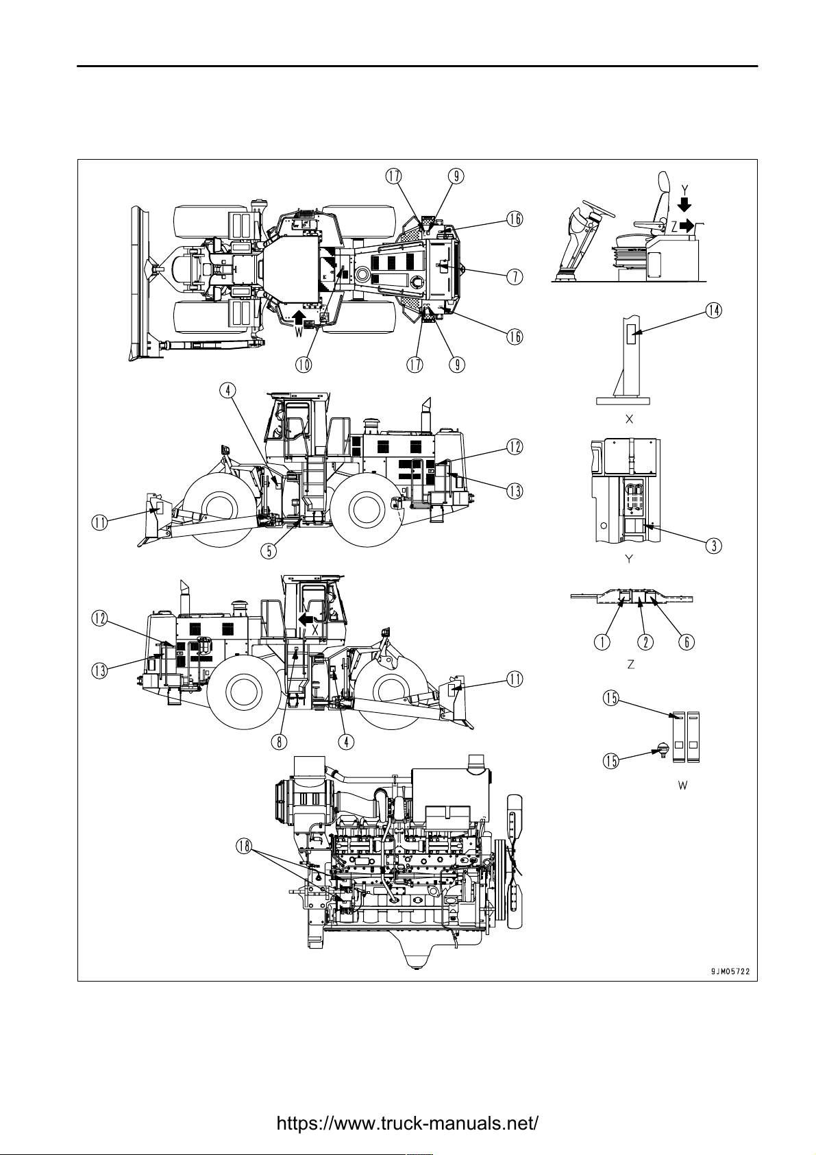
GENERAL VIEW OF MACHINE
3 - 2
(1) Blade
(2) Head lamp
(3) Front working lamp
(4) Turn signal lamp
(5) ROPS
(6) Rear wheel
(7) Front wheel
(8) Lift cylinder
(9) Tilt/pitch cylinder
(10) Rear working lamp
(11) Rear combination lamp
Page 52

.
OPERATION
GENERAL VIEW
GENERAL VIEW OF CONTROLS AND GAUGES
3 - 3
(1) Front wiper switch
(2) Rear wiper switch
(3) Engine troubleshooting lamp
(4) Gearshift lever stopper
(5) Air conditioner panel (if equipped)
(6) Gearshift lever
(7) Directional lever
(8) Hazard lamp
(9) Horn switch
(10) Main monitor
(11) Steering wheel
(12) Lamp switch
(12) Turn signal lever
(12) Dimmer switch
(13) Parking brake switch
(14) Starting switch
(15) Car radio (if equipped)
(16) Kickdown switch
(17) Tilt or pitch switch
(18) Blade control lever
(19) Cigarette lighter
(20) RPM set idle up-down selector switch
(21) RPM set on-off switch
(22) Power window switch
(23) Maintenance monitor
(24) Safety lock lever
(25) Accelerator pedal
(26) Brake pedal
(27) Steering column tilt lever
(28) Brake pedal
Page 53

.
OPERATION
GENERAL VIEW
3 - 4
MAIN MONITOR MAINTENACNE MONITOR
(1) Emergency steering pilot lamp (if equipped)
(2) Turn signal pilot lamp
(3) High beam pilot lamp
(4) Central check lamp
(5) Preheating pilot lamp
(6) Front working lamp (switch, pilot lamp)
(7) Rear working lamp (switch, pilot lamp)
(8) Transmission cut-off (switch, pilot lamp)
(9) Transmission auto-shift/manual selector (switch,
pilot lamp) (if equipped)
(10) Parking brake pilot lamp
(11) Central caution lamp
(12) Speedometer
(13) Transmission shift indicator
(14) Fuel gauge
(15) Engine water cooling temperature gauge
(16) Torque converter oil temperature gauge
(17) Air cleaner clogging caution pilot lamp
(18) Service meter
(19) Battery charge caution pilot lamp
(20) Brake oil pressure caution pilot lamp
(21) Engine oil pressure caution pilot lamp
(22) Engine oil level caution pilot lamp
(23) Engine water level caution pilot lamp
Page 54

.
OPERATION
EXPLANATION OF COMPONENTS
EXPLANATION OF COMPONENTS
MACHINE MONITOR
MONITOR SYSTEM
3 - 5
The following is an explanation of the devices needed for operating the machine.
To carry out suitable operations correctly and safely, it is important to understand fully the methods of operating the
equipment and the meanings of the displays.
A: Meter display portion
B: Warning display portion
C: Meter display portion
The machine monitor system is made up of the main monitor (located in front of the operator's seat), maintenance
monitor (located at the right hand of the operator's seat) and engine troubleshooting lamp (located in the lower left
portion in front of the operator's seat).
The monitor system can be divided functionally into the alarm display portions (B, E, and F) and the meter display
portions (A, C, and D).
D: Meter display portion
E: Warning display portion
F: Warning display portion
Page 55

.
OPERATION
EXPLANATION OF COMPONENTS
These
monitors
do
not
guarantee
the
condition
of
the
machine.
Do
not
simply
relyonthe
monitor
when
carrying
out
checks
before
starting
(daily
inspection).
Always
get
off
the
machine
and
check
each
item
directly.
WARNING DISPLAYS
METER DISPLAY PORTION
TESTING ACTUATION OF MACHINE MONITOR SYSTEM
3 - 6
(B, E, and F) See "WARNING DISPLAY (PAGE 3-7)".
This consists of the central check lamp, central warning lamp, warning pilot lamp (engine water level, engine oil
level, brake oil pressure, engine oil pressure, battery charge, and clogging of air cleaner), and engine
troubleshooting lamp.
See (A, C, D) "METER DISPLAY PORTION (PAGE 3-13)".
This consists of the meters (speedometer, fuel gauge, engine water temperature gauge, torque converter oil
temperature gauge, service meter, and transmission shift indicator) and the pilot lamps (turn signal indicator, head
lamp Hi beam, preheating, front working lamp, rear working lamp, transmission cut-off, parking brake, emergency
steering, and transmission auto-shift/manual selector).
When the starting switch is turned to the ON position before starting the engine, all monitor lamps, gauges, and
centralized warning lamps will light up for approx. 3 seconds, and the alarm buzzer will sound for approx. 1 second.
When this happens, 88 is displayed on the speedometer, and 8 is displayed on the transmission shift indicator.
Finally, there will be two beeps to indicate that the monitor check has been completed.
If the monitor lamps do not light up, there is probably a failure or disconnection, so please contact your Komatsu
distributor for inspection.
When the starting switch is turned to the ON position, if the directional lever is not at the neutral position, the central
warning lamp (CAUTION) will flash and the alarm buzzer will sound intermittently. If this happens, return the lever
to the neutral position, and the lamps will go out and the buzzer will stop.
The monitor check cannot be carried out for at least 30 seconds after the engine has been stopped.
The engine troubleshooting lamps (3 lamps: red, yellow, and orange) light up for approximately 2 seconds when the
starting switch is turned ON. If a lamp does not light up, ask your Komatsu distributor check it.
Page 56

.
OPERATION
EXPLANATION OF COMPONENTS
WARNING DISPLAY
3 - 7
(1) Central check lamp (CHECK)
(2) Central caution lamp (CAUTION)
(3) Engine water level caution pilot lamp
(4) Engine oil level caution pilot lamp
(5) Brake oil pressure caution pilot lamp
(6) Engine oil pressure caution pilot lamp
(7) Battery charge caution pilot lamp
(8) Air cleaner clogging caution pilot lamp
(9) Emergency steering pilot lamp (red) (if equipped)
(10) Engine troubleshooting lamp
Page 57

.
OPERATION
EXPLANATION OF COMPONENTS
CENTRAL CHECK LAMP (CHECK)
If
this
monitor
flashes,
carry
out
inspection
and
maintenance
of
the
appropriate
location
as
soonaspossible.
CENTRAL CAUTION LAMP (CAUTION)
If
this
monitor
flashes,
stop
the
engine
immediately
or
runitat
low
idling
anddoas
follows.
3 - 8
If any abnormality is found in the CHECK items before starting
the engine (engine oil level, engine water level), the monitor
lamp for the abnormal location will flash and central check lamp
(CHECK) (1) will also flash.
Check the location where the monitor lamp is flashing and carry
out the check before starting.
When carrying out the checks before starting, do not rely simply
on the monitor. Always carry out the specified check before
starting items "CHECK BEFORE STARTING (PAGE 4-33)".
When carrying out checks before starting, if the engine oil level
is abnormal, the engine oil level will change when the engine is
started, so even if there is any abnormality, the central check
lamp and monitor lamp will stop flashing.
If there is any abnormality in the engine water level, the central
check lamp will go out when the engine is started, but instead of
this, the central caution lamp will flash and the alarm buzzer will
sound intermittently.
If there is any abnormality in the battery charging system when
the engine is running, the battery charge caution pilot lamp will
flash and the central CHECK lamp (1) will also flash at the same
time. If the lamps flash, check the charging circuit.
If there is an abnormality in any CAUTION item when the engine
is running (engine water temperature, torque converter oil
temperature, engine water level, brake oil pressure, engine oil
pressure), the alarm buzzer will sound intermittently and the
monitor lamp for the location of the abnormality will flash and the
central CAUTION lamp (2) will also flash.
If the fuel gauge enters the red range when the engine is
running, the fuel gauge will flash and the central CAUTION lamp
(2) will also flash. If they flash, check the fuel level and add fuel.
Page 58

.
OPERATION
EXPLANATION OF COMPONENTS
ENGINE WATER LEVEL CAUTION PILOT LAMP
ENGINE OIL LEVEL CAUTION PILOT LAMP
3 - 9
This lamp (3) warns that the coolant level in the radiator has
dropped.
When carrying out the checks before starting (starting switch ON,
engine stopped):
If the level of the coolant in the radiator is low, the caution pilot lamp
and central CHECK lamp will flash.
If the monitor lamps flash, check the coolant level in the radiator
sub-tank and add water.
When operating (engine running):
If the condition is normal, the caution pilot lamp should be off. If the
level of the coolant in the radiator is too low, the warning pilot lamp
and central CAUTION lamp will flash, and the alarm buzzer will
sound intermittently.
If the monitor lamps flash, stop the engine, check the level of the
coolant in the radiator, and add water.
Stop the machine on level ground before carrying out this check.
This lamp (4) warns the operator that the level of the oil in the
engine oil pan has dropped.
When carrying out checks before starting:
If the oil level in the engine oil pan is low, the caution pilot lamp and
central CHECK lamp will flash.
If the monitor lamps flash, check the oil level in the engine oil pan
and add oil.
When operating:
Even if the engine oil level caution pilot lamp is flashing during
check before starting, it will go out when the engine is started.
Page 59

.
OPERATION
EXPLANATION OF COMPONENTS
BRAKE OIL PRESSURE CAUTION PILOT LAMP
REMARK
ENGINE OIL PRESSURE CAUTION PILOT LAMP
BATTERY CHARGE CAUTION PILOT LAMP
3 - 10
This lamp (5) warns the operator that the brake oil pressure has
dropped.
When carrying out checks before starting:
When the engine is stopped, the brake oil pressure circuit is not
actuated, so the caution pilot lamp and central CHECK lamp are
also off.
When operating:
If the brake oil pressure goes down, the caution pilot lamp and
central CAUTION lamp will flash, and the alarm buzzer will sound
intermittently. If the monitor lamps flash, stop the engine
immediately and check the brake oil pressure circuit.
The monitor lamp may flash and go out after approx. 10 seconds immediately after the engine is started. This is
because pressure is being stored in the brake accumulator. It does not indicate any abnormality.
This lamp (6) warns the operator that the engine lubricating oil
pressure has dropped.
If it flashes, stop the engine and check.
Check before starting: Lights up
Engine started or running:
When the engine is started, the lubrication pressure is formed and
the lamps go out. If the engine lubrication pressure drops, the
warning pilot lamp and central CAUTION lamp will flash, and the
buzzer will sound intermittently.
This lamp (7) warns the operator that there is an abnormality in the
charging system when the engine is running.
Check before starting: Lights up
Engine started or running:
When the engine is started, the alternator generates electricity and
the lamp goes out.
If any abnormality occurs in the charging system, the caution pilot
lamp and central CHECK lamp will flash. If they flash, check the
charging circuit.
Page 60

.
OPERATION
EXPLANATION OF COMPONENTS
AIR CLEANER CLOGGING CAUTION PILOT LAMP
EMERGENCY STEERING PILOT LAMP
3 - 11
When the engine is running, this lamp (8) warns the operator that
the air cleaner element is clogged.
Check before starting: OFF
When operating:
If the air cleaner becomes clogged, the caution pilot lamp and
central CHECK lamp will flash.
If they flash, clean or replace the element.
(If equipped)
This lamp (9) indicates that the engine has stopped when the
machine is traveling, or there is any abnormality in the pump circuit.
The monitor flashes (red ) to indicate that the emergency steering
system has been actuated. If the monitor flashes, stop the engine
immediately.
Page 61

.
OPERATION
EXPLANATION OF COMPONENTS
ENGINE TROUBLESHOOTING LAMP
REMARK
3 - 12
If the abnormality occurs in the engine, engine troubleshooting
lamp (10) lights up.
There is an abnormality in the engine when either one of three
lamps (red, yellow, and orange) in the troubleshooting indicator
lights up while the machine is moving. Follow the instruction below
if this occurs.
Orange lamp lights up:
It indicates that engine controller records the abnormality.
Although the engine can be operated, the measured value
detected by the sensor is not within the normal range.
Ask your Komatsu distributor to check it immediately.
Yellow lamp lights up:
Although the engine can be operated, there is trouble.
It may cause the decrease of power.
Ask your Komatsu distributor to repair it immediately.
Red lamp lights up:
Immediately move the machine to the safe ground and stop the
engine. Contact your Komatsu distributor.
To confirm the engine operation, all 3 colors of engine troubleshooting lamps light up for approximately 2 seconds
after the starting switch is turned ON, even if the engine is in normal condition.
Page 62

.
OPERATION
EXPLANATION OF COMPONENTS
METER DISPLAY PORTION
PILOT DISPLAY
PARKING BRAKE PILOT LAMP
3 - 13
(1) Parking brake pilot lamp
(2) Preheating pilot lamp
(3) Front working lamp pilot lamp
(4) Rear working lamp pilot lamp
(5) Transmission cut-off pilot lamp
(6) Turn signal pilot lamp
(7) High beam pilot lamp
(8) Transmission auto-shift/manual selectior pilot
lamp (if equipped)
When the starting switch is ON, the pilot display lights up when the display items are functioning.
This lamp (1) lights up when the parking brake is applied.
(9) Fuel gauge
(10) Engine water cooling temperature gauge
(11) Torque converter oil temperature gauge
(12) Service meter
(13) Speedometer
(14) Transmission shift indicator
Page 63

.
OPERATION
EXPLANATION OF COMPONENTS
PREHEATING PILOT LAMP
FRONT WORKING LAMP PILOT LAMP
REAR WORKING LAMP PILOT LAMP
TRANSMISSION CUT-OFF PILOT LAMP
3 - 14
This lamp (2) informs the operator of the preheating status of the
electrical intake air heater.
This lamp lights up when the starting switch is turned to the ON
position, and goes out when the preheating is completed.
The time that it remains lighted up differs according to the water
temperature when the engine is started.
This lamp (3) lights up when the front working lamp is switched on.
This lamp (4) lights up when the rear working lamp is switched on.
This lamp (5) lights up when the transmission cut-off switch is
turned to ON.
If the monitor lamp is ON and the left brake pedal is depressed, the
transmission will be returned to neutral.
Page 64

.
OPERATION
EXPLANATION OF COMPONENTS
TURN SIGNAL PILOT LAMP
HIGH BEAM PILOT LAMP
TRANSMISSION AUTO SHIFT/MANUAL SELECTOR PILOT LAMP
METERS
FUEL GAUGE
3 - 15
When the turn signal lamp flashes, this lamp (6) also flashes.
This lamp (7) lights up when the head lamp is at high beam.
(If equipped)
This lamp (8) lights up when the transmission auto-shift/manual
selector switch is operated and the transmission shift is changed
to manual mode.
When the monitor is lighted up, the transmission speed range can
be changed by operating the gearshift lever.
This gauge (9) indicates the amount of fuel in the fuel tank.
E: Tank is EMPTY
F: Tank is FULL
The lamp should light up in the green range during operation.
If it enters the red range during operation, the fuel gauge lamp and
central CAUTION lamp will flash.
If only the red range lights up during operation, it means that there
is less than 85 liters (22.44 US gal) of fuel left, so check and add
fuel.
Page 65

.
OPERATION
EXPLANATION OF COMPONENTS
ENGINE COOLING WATER TEMPERATURE GAUGE
TORQUE CONVERTER OIL TEMPERATURE GAUGE
SERVICE METER
SPEEDOMETER
3 - 16
This gauge (10) indicates the temperature of the cooling water.
If the temperature is normal during operation, the green range will
light.
If the red range lights during operation, stop the machine and run
the engine with no load at midrange speed until the green range
lights.
If the lamps light up to the 1st red level, the engine water
temperature gauge lamp and central CAUTION lamp will flash;
when the lamps light up to the 2nd red level, the alarm buzzer will
also sound intermittently.
This gauge (11) indicates the temperature of the torque converter
oil. If the temperature is normal during operation, the green range
will light.
If the red range lights during operation, stop the machine and run
the engine with no load at midrange speed until the green range
lights.
If the lamps light up to the 1st red level, the torque converter oil
temperature gauge lamp and central CAUTION lamp will flash;
when the lamp lights up to the 2nd red level, the alarm buzzer will
also sound intermittently.
This meter (12) shows the total operation hours of the machine.
The service meter advances while the engine is running - even if
the machine is not traveling.
While the engine is running, green pilot lamp on the service meter
flashes to show the service meter advances.
The service meter progresses by 1 when the engine is operated for
one hour, regardless of the engine speed.
This meter (13) indicates the travel speed of the machine.
Page 66

.
OPERATION
EXPLANATION OF COMPONENTS
TRANSMISSION SHIFT INDICATOR
WHEN USING JOYSTICK STEERING SYSTEM
REMARK
3 - 17
This (14) indicates the present speed range of the transmission.
When the directional lever is at the N position, N is displayed on the
indicator.
When the directional lever is at the F or R position, the shift position
of the speed lever is displayed as a numeral.
(If equipped)
This indicates the transmission speed range. When the N button of the FNR buttons on the head of the joystick lever
is pressed, the indicator displays N.
When the auto-shift (if equipped) is employed:
The transmission speed range is indicated.
The auto-shift is installed on machines with the joystick steering
system. The shift indicator shown on the right is installed as well.
When the F (FORWARD) or R (REVERSE) buttons of the FNR
buttons on the head of the joystick lever are pressed, F or R is
displayed at the bottom of the speedometer and the shift indicator
displays the transmission speed range and N.
Page 67

.
OPERATION
EXPLANATION OF COMPONENTS
SWITCHES
3 - 18
(1) Starting switch
(2) Transmission cut-off switch
(3) Front working lamp switch
(4) Rear working lamp switch
(5) Transmission auto-shift/manual selector switch (if
equipped)
(6) Lamp switch
(6) Turn signal lever
(6) Dimmer switch
(7) Horn button
(8) Hazard lamp switch
(9) Kickdown switch
(10) Front wiper switch
(11) Rear wiper switch
(12) Cigarette lighter
(13) Room lamp switch
(14) Parking brake switch
(15) Power window switch (right)
(16) Power window switch (left)
(17) Tilt or pitch switch
(18) RPM set on-off switch
(19) RPM set idle up-down selector switch
Page 68

.
OPERATION
EXPLANATION OF COMPONENTS
STARTING SWITCH
TRANSMISSION CUT-OFF SWITCH
When
moving
the
machine
offonan
uphill
slope,
set
the
transmission
cut-off
switch
to
the
OFF
position,
depress
the
accelerator
pedal
while
keeping
the
left
brake
pedal
depressed,
then
gradually
release
the
brake
pedal
and
allow
the
machine
to
move.
Inthis
way
the
machine
canbeprevented
from
traveling
backwards.
3 - 19
This switch (1) is used to start or stop the engine.
OFF: The key can be inserted and removed at this position. When
the key is turned to this position, all electrical circuits are turned off
and the engine stops.
In addition, the parking brake is automatically applied.
ON position
Electric current flows in the charging circuit, lamp circuit, and
accessory circuit.
Keep the starting switch key at the ON position while the engine is
running.
START position
This is the position to start the engine. Hold the key at this position while cranking. Release the key immediately
after the engine has been started. The key will return to the ON position when released.
Press this push button switch (2) to turn ON or OFF.
When the pilot lamp is pressed, it will light up and come ON; if it
pressed again, the pilot lamp will go out and the transmission
cut-off will be turned OFF. Set at ON position normally.
OFF: Left brake pedal acts as normal brake (like right brake pedal).
ON: Left brake pedal acts as normal brake, but also switches
transmission to NEUTRAL.
If the switch is turned to ON, the transmission cut-off pilot lamp will
light up.
Page 69

.
OPERATION
EXPLANATION OF COMPONENTS
FRONT WORKING LAMP SWITCH
Always
turn
the
working
lamp
off
before
traveling
on
public
roads.
REAR WORKING LAMP SWITCH
Always
turn
the
working
lamp
off
before
traveling
on
public
roads.
TRANSMISSION AUTO SHIFT/MANUAL SELECTOR SWITCH
REMARK
3 - 20
When turning on the front working lamp, turn the lamp switch to the
ON position for the side clearance lamp or ON position for the head
lamp, then operate the switch (3).
When the pilot lamp is pressed, it will light up and come ON; if it
pressed again, the pilot lamp will go out and the working lamp will
be turned OFF.
The working lamp will not light up if the lamp switch is not at the ON
position for the side clearance lamp or ON position for the head
lamp.
When turning on the rear working lamp, turn the lamp switch to the
ON position for the side clearance lamp or ON position for the head
lamp, then operate the switch (4).
When the pilot lamp is pressed, it will light up and come ON; if it
pressed again, the pilot lamp will go out and the working lamp will
be turned OFF.
The working lamp will not light up if the lamp switch is not at the ON
position for the side clearance lamp or ON position for the head
lamp.
(if auto-shift equipped)
Press this push button switch (5) to turn ON or OFF.
If the switch is pressed once, the pilot lamp lights up and the
system is turned ON; if the switch is pressed again, the pilot lamp
goes out and the system is turned OFF.
Normally, set it to the OFF position.
OFF: Transmission set to auto shift
ON: Transmission set to manual shift
When the switch is at the ON position, the transmission AUTO
SHIFT/MANUAL selector pilot lamp lights up.
For details of manual gear, see "GEARSHIFT LEVER (PAGE 3-27)". For details of automatic gear shifting (if
equipped), see "HANDLING AUTOMATIC SHIFT SYSTEM (PAGE 6-2)",
Page 70

.
OPERATION
EXPLANATION OF COMPONENTS
LAMP SWITCH
REMARK
TURN SIGNAL LEVER
REMARK
DIMMER SWITCH
HORN BUTTON
3 - 21
This switch (6) is used to light up the front lamps, side clearance
lamps, tail lamps, and instrument panel.
Position (a): OFF
Position (b): Side clearance lamps, tail lamps, and instrument
panel light up
Position (c): Head lamps light up in addition to lamps at (b) position
The lamp switch can be operated regardless of the position of the
lever.
This switch (6) is used to operate the turn signal lamp.
(a) position : LEFT TURN (Push lever FORWARD.)
(b) position : RIGHT TURN (Pull lever BACK.)
When the lever is operated, the pilot lamp turn signal pilot lamp
also flashes.
When the steering wheel is turned back, the lever automatically
returns to its original position. If it does not return, return it by
hand.
This switch (6) is used to switch the head lamps between high
beam and low beam.
Position (a): Low beam
Position (b): High beam
When the horn button (7) in the center of the steering wheel is
pressed, the horn will sound.
Page 71

.
OPERATION
EXPLANATION OF COMPONENTS
HAZARD LAMP SWITCH
Use
the
hazard
lamp
onlyinemergencies.
Using
the
hazard
lamp
when
traveling
will
cause
problems
for
other
machines.
REMARK
KICKDOWN SWITCH
REMARK
FRONT WIPER SWITCH
3 - 22
This switch (8) is used in emergencies, such as when the machine
breaks down and has to be parked on the road.
ON position: All turn signal lamps flash.
When this switch is turned to the ON position, the turn direction
indicator lamps and turn indicator pilot lamp flash, and display lamp
(A) lights up at the same time.
When the gearshift lever is in 2nd, and the switch (9) at the top of
the knob of the blade control lever is pressed, the gear will shift
down to 1st.
Use this when you need to increase the drawbar pull in digging
operations.
To cancel the kickdown switch, move the directional lever to
REVERSE or NEUTRAL, or move the speed control lever to any
position except 2nd. It is also possible to cancel the kickdown
switch by operating the parking brake switch or by turning the
starting switch OFF.
Turn rotary switch (A) of switch (10) to operate the front wiper.
If push button (B) is pressed, washer liquid will be sprayed out onto
the front glass while the button is being pressed.
Position(a): (OFF) stop
Position(b): (INT)Intermittent wiper
Position(c): Low-speed wiper
Position(d): High-speed wiper
Page 72

.
OPERATION
EXPLANATION OF COMPONENTS
REAR WIPER SWITCH
CIGARETTE LIGHTER
ROOM LAMP SWITCH
REMARK
3 - 23
Turn lever (C) on switch (11) to operate the rear wiper.
Position (a): Washer liquid is sprayed out
Position (b): OFF
Position (c): Wiper is operated
Position (d): Washer liquid is sprayed out, wiper is operated
This is used to light cigarettes.
If the cigarette lighter (12) is pushed in, it will return to its original
position after several seconds. When it returns, pull it out and light
the cigarette.
This switch (13) lights up the room lamp.
Position (a): OFF
Position (b): Lights up when cab door is opened
Position (c): Lights up
The room lamp lights up even when the main switch is OFF, so
when leaving the operator's compartment, turn the switch to
position (a) (OFF) or (b).
When operating with the cab door fully open, set the switch to
position (a) (OFF).
Page 73

.
OPERATION
EXPLANATION OF COMPONENTS
PARKING BRAKE SWITCH
Always
apply
the
parking
brake
when
leaving
the
machine
or
when
parking
it.
Evenifthe
parking
brake
switch
is
turned
ON,
there
is
danger
until
the
parking
brake
pilot
lamp
lights
up,sokeep
the
brake
pedal
depressed.
NOTICE
Never
use
the
parking
brake
switch
to
apply
the
brakes
when
traveling,
except
inanemergency.
Apply
the
parking
brake
only
after
the
machine
has
stopped.
If
the
parking
brake
has
been
usedasan
emergency
brake
when
traveling
at
high
speed
(near
the
maximum
speed),
contact
your
Komatsu
distributor
to
have
the
parking
brake
checked
for
any
abnormality.
REMARK
3 - 24
This switch (14) is used for actuating the parking brake.
Position (a): ON
The parking brake is applied, and the parking brake
pilot lamp lights up.
Position (b): OFF
The parking brake is released.
If the directional lever is placed in F (FORWARD) or R
(REVERSE) with the parking brake applied, the warning lamp
will flash and the alarm buzzer will sound.
Before starting the engine, turn the parking brake switch to ON,
then turn it to OFF.
The machine does not start when the directional lever is
operated with the parking brake applied.
Page 74

.
OPERATION
EXPLANATION OF COMPONENTS
POWER WINDOW SWITCH
Be
careful
nottoget
anyone's
hands
or
head
caught
when
closing
the
window.
There
is
danger
of
serious
personal
injury
if
anyone
gets
their
hands
or
head
caught
in
the
window.
Do
not
continue
to
operate
the
switch
when
the
window
is
fully
openorfully
closed.
This
will
cause
failure
of
the
power
window.
TILT OR PITCH SWITCH
RPM SET ON-OFF SWITCH
REMARK
3 - 25
These switches (15), (16) can be used while the engine switch is
at the ON position.
When portion (A) is pressed, the side window goes down.
When portion (B) is pressed, the side window goes up.
When the window reaches the top or bottom and the window stops
moving, release the switch immediately.
This switch (17) is used for pitch operation of the blade.
To operate the blade to pitch, keep to press down switch (A) or (B)
and operate the blade control lever.
(When not pressing down the switch, the lever works for tilt
operation.)
This switch (18) is used to turn the power for the RPM set system
ON-OFF.
Position (A): Power for system is turned ON
The switch icon lights up.
Position (B): Power for system is turned OFF
The switch icon goes out.
The RPM SET ON-OFF switch is used only for turning the power to the RPM set system ON or OFF. To set the
engine speed, use the RPM set IDLE UP-DOWN selector switch.
This switch is a seesaw switch, so do not press it unnecessarily.
Page 75

.
OPERATION
EXPLANATION OF COMPONENTS
RPM SET IDLE UP-DOWN SELECTOR SWITCH
When
the
RPM
set
ON-OFF
switch
or
engine
starting
switch
are
turned
OFF,
the
idling
up
(down)
speed
recorded
in
memory
is
cleared.
Toset
the
speed
again,
carry
out
the
procedure
again
from
the
beginning.
If
the
right
brake
pedal
is
depressed
when
the
speed
has
been
setbythe
RPM
set
idling
up
(down)
selector
switch,
the
engine
speed
recorded
in
memory
is
lowered
to
the
idling
speed,
but
when
portion
(B)ofthe
switch
is
pressed,
the
engine
returns
to
its
original
speed.
To
operate
the
switch,
check
that
the
RPM
set
ON-OFF
switch
isattheONposition.
IfitisON,
the
RPM
set
switch
icon
lights
up.
3 - 26
This switch (19) keeps the engine speed at the desired speed.
Position (A):
Use this position when setting the engine speed and when raising
the set speed.
When using the accelerator pedal
Depress the accelerator pedal to raise the engine speed to the
desired speed, then press portion (A) of the switch. The speed
is recorded in memory.
When using the RPM set idling up/down switch
Keep portion (A) of the switch pressed to raise the engine speed by 100 rpm each second. When the engine
reaches the desired speed, release the switch. The new speed is recorded to memory and the setting is made.
Position (B):
Use this position when lowering the engine speed or when resetting after canceling the RPM set switch.
When using the RPM set up/down switch
Keep portion (B) of the switch pressed to lower the engine speed by 100 rpm each second. When the engine
reaches the desired speed, release the switch. The new speed is recorded to memory and the setting is made.
Page 76

.
OPERATION
EXPLANATION OF COMPONENTS
CONTROL LEVERS, PEDALS
GEARSHIFT LEVER
3 - 27
(1) Gearshift lever
(2) Directional lever
(3) Gearshift lever stopper
(4) Safety lock lever (for blade control lever)
This lever (1) changes the speed range of the transmission.
This machine has a 4-FORWARD, 4-REVERSE speed
transmission.
Place the gearshift lever in a suitable position to obtain the desired
speed range.
1st and 2nd speeds are used for working.
3rd and 4th speeds are used for traveling.
However, when the gearshift lever stopper is being used, it is
impossible to shift to 3rd or 4th. Disengage the gearshift lever
stopper before trying to shift gear.
Position (a): 1st
Position (b): 2nd
Position (c): 3rd
Position (d): 4th
(5) Blade control lever
(6) Brake pedal
(7) Accelerator pedal
Page 77

.
OPERATION
EXPLANATION OF COMPONENTS
OPERATION
EXPLANATION OF COMPONENTS
REMARK
DIRECTIONAL LEVER
REMARK
GEARSHIFT LEVER STOPPER
3 - 28
The length of the lever can be adjusted to 3 stages (positions (A),
(B), (C)). To adjust the length, remove the screw at the bottom of
the lever knob, slide the knob to the desired position, then tighten
the screw again.
(The lever is installed to position (B) when it is shipped from the
factory.)
This lever (2) is used to switch the direction of travel of the machine
between forward and reverse.
When starting the engine, if the directional lever is not at the N
position, the engine will not start.
Position (a): FORWARD
Position N: NEUTRAL
Position (b): REVERSE
The length of the lever can be adjusted to 3 stages (positions (A),
(B), (C)). To adjust the length, remove the screw at the bottom of
the lever knob, slide the knob to the desired position, then tighten
the screw again.
(The lever is installed to position (B) when it is shipped from the
factory.)
This stopper (3) prevents the gearshift lever from entering the 3rd
or 4th positions when working.
Position (a): Stopper actuated.
Position (b): Stopper released.
Page 78

.
OPERATION
EXPLANATION OF COMPONENTS
SAFETY LOCK LEVER (FOR BLADE CONTROL LEVER)
When
leaving
the
operator's
compartment,
set
the
safety
lock
lever
securely
to
the
LOCK
position.
If
the
safety
lock
leverisnot
locked,
and
the
blade
control
lever
(A)istouched
by
mistake,
this
may
leadtoa
serious
accident.
If
the
safety
lock
leverisnot
placed
securely
in
the
LOCK
position,
the
blade
control
lever
may
notbeproperly
locked.
Check
that
the
situation
isasshown
in
the
diagram.
When
the
safety
lock
leverispulled
up,donot
touch
the
blade
control
lever
(A).
BLADE CONTROL LEVER
REMARK
3 - 29
This lever (4) is a lock device for the blade control lever.
Push the safety lock lever down to lock it.
This lever (5) is used to operate the blade tilt and lift.
BLADE TILT OPERATION
Position (a): LEFT TILT
Position (b): HOLD
The blade is kept in the same position
Position (c): RIGHT TILT
If the lever is released at position (a) or (c), the lever will return to
the HOLD position.
Page 79

.
OPERATION
EXPLANATION OF COMPONENTS
OPERATION
EXPLANATION OF COMPONENTS
REMARK
3 - 30
BLADE LIFT OPERATION
Position (a): RAISE
Position (b): HOLD
The blade is kept in the same position
Position (c): LOWER
Position (d): FLOAT
The blade moves freely under external force.
If the lever is released at this position, it will not return
to the HOLD position, so return it manually.
If the lever is released at position (a) or (c), the lever will return to
the HOLD position.
BLADE PITCH OPERATION
Keep the switch (A) or (B) at the tip of the lever pressed and
operate the lever. If switch (A) or (B) is not kept pressed when the
lever is operated, it will be impossible to carry out the blade pitch
operation.
Position (a): REAR PITCH
Position (b): HOLD
Position (c): FORWARD PITCH
Page 80

.
OPERATION
EXPLANATION OF COMPONENTS
BRAKE PEDAL
When
traveling
downhill,
use
the
engine
asabrake,
and
always
use
the
right
brake
pedal.
Do
not
use
the
brake
pedals
repeatedly
unless
necessary.
Do
not
put
your
footonthis
pedal
unless
necessary.
RIGHT BRAKE PEDAL
LEFT BRAKE PEDAL
REMARK
ACCELERATOR PEDAL
3 - 31
These pedals (6) operate the brakes.
The right brake pedal operates the wheel brakes.
Use the right brake pedal for normal braking operations.
The left brake pedal operates the wheel brakes.
When the transmission cut-off switch is in the ON position, and if this brake pedal is depressed, wheel brakes are
applied and the transmission is set to the neutral position at the same time. If the transmission cut-off switch is at
OFF, the left brake pedal acts in the same way as the right brake pedal.
When the accelerator is being used for operating the work equipment, always set the transmission cut-off switch to
the ON position and use the left brake pedal to slow or stop the machine.
This pedal (7) controls the engine speed and output.
The engine speed can be freely controlled between low idling and
full speed.
Page 81

.
OPERATION
EXPLANATION OF COMPONENTS
STEERING COLUMN TILT LEVER
Stop
the
machine
before
adjusting
the
tiltofthe
steering
wheel.
Ifthis
operation
(adjustment)
is
carried
out
while
the
machine
is
moving,
it
may
leadtoa
serious
accident
or
personal
injury.
3 - 32
This lever allows the steering column to be tilted forward or
backward.
Pull the lever up and move the steering wheel to the desired
position. Then push the lever down to lock the steering wheel in
position.
Range of adjustment:125 mm (4.9 in) (stepless)
Page 82

.
OPERATION
EXPLANATION OF COMPONENTS
CAP WITH LOCK
METHOD OF OPENING AND CLOSING CAP WITH LOCK
TO OPEN THE CAP
TO LOCK THE CAP
3 - 33
A lock is provided on the caps for fuel tank oil filler port, transmission oil filler port (if equipped) and hydraulic tank
oil filler port (if equipped). Use the engine starting switch for opening - closing the cap.
Insert the starting switch key into the cap as far as it will go (to
1.
the shoulder).
If the starting switch key is turned before it is inserted all the
way, it may break.
Turn the starting switch key counterclockwise and bring the
2.
rotor groove in line with the aligning mark on the cap. Turn the
cap slowly until a "clicking" sound is made. This releases the
lock and allows the cap to be opened.
Screw the cap into place.
1.
2. Turn the starting switch key counterclockwise and take the key out.
Page 83

.
OPERATION
EXPLANATION OF COMPONENTS
SAFETY BAR
If
safety
barisunlocked,
machine
can
jackknife
unexpectedly
when
itisbeing
transported
or
hoisted.
Jackknifing
can
cause
serious
injury
or
death
tobystanders.
Always
lock
safety
bar
when
machine
is
being
transported
or
hoisted.
If
necessary,
lock
safety
bar
during
servicing
or
maintenance.
TOWING PIN
3 - 34
The safety bar is used locks the front and rear frames, and
prevents the front and rear frames from pivoting.
Lock position: Always lock safety bar when machine is being
transported or hoisted.
If necessary, lock safety bar during servicing or
maintenance.
Free position: Always remove the safety bar for travel operations.
1. Insert towing pin (1) into hole (2) in the counterweight.
Use linch pin (3) to set so that the towing pin does not come
2.
out.
Carry out this operation in reverse to remove the pin.
Page 84

.
OPERATION
EXPLANATION OF COMPONENTS
GREASE PUMP
BACKUP ALARM
DUST INDICATOR
3 - 35
The grease pump is stored in the engine hood at the rear of the
machine. After using it, wipe off all grease stuck to its outside of the
pump, then store it.
The clamp and rubber ring that secure the grease pump are seen
when the engine side panel is opened. Set the grease pump in the
clamp and attach the chain to the clamp to prevent any play.
In addition, attach the rubber ring in a figure eight, as shown in the
diagram on the right, to hold the grease pump in position.
This sounds an alarm when the directional lever is set to the R
position. It is used to warn people behind the machine that the
machine will travel in reverse.
This device indicates clogging of the air cleaner.
Depending on the degree of clogging of the element, red line (1)
appears in the transparent portion. If red line (1) indicates 0.0075
MPa (30 INCHES H2O) (0.076 kgf/cm2, 1.1 PSI), clean the element
immediately.
After cleaning, press top portion (2) of the indicator to return red
line (1) to its original position.
Page 85

.
OPERATION
EXPLANATION OF COMPONENTS
CAB DOOR OPEN LOCK
TOOL BOX
OIL FILLER LOCATION
FUSE
NOTICE
Before
replacing
a
fuse,besuretoturn
off
the
starting
switch.
3 - 36
This can be used to hold the door open.
Open the door so that tip (2) of the lever is aligned with groove (1)
of the lock, then pull down knob (3) as shown in the diagram.
When using the door-open lock, be sure to apply the lock securely.
When releasing the lock and closing the door, push up knob (3)
and insert pin (4) securely into the groove.
The tool box is installed under the step on the left side of the
machine. Use it to store tools, etc..
The 4th step from the bottom rung of a ladder provided at the right
side of machine is big enough on which to place a large-sized oiler.
Use of that step is recommended particularly when raising oil up to
the top of machine.
The fuses protect the electrical equipment and wiring from burning
out.
If the fuse becomes corroded, or white powder can be seen, or the
fuse is loose in the fuse holder, replace the fuse.
Replace the fuse with another of the same capacity.
Page 86

.
OPERATION
EXPLANATION OF COMPONENTS
FUSE CAPACITY AND NAME OF CIRCUIT
FUSE BOX 1
FUSE BOX 2
3 - 37
No. Fuse capacity Name of circuit
(1) 20A Main lamp circuit
(2) 20A Backup lamp, brake lamp
(3) 10A Turn signal idicator lamp
(4) 10A R.H. head lamp
(5) 10A L.H. head lamp
(6) 10A R.H. side clearance lamp
(7) 10A L.H. side clearance lamp
(8) 10A Parking brake
(9) 10A Transmission control
(10) 10A Instrument panel
(11) 10A Joystick steering (if equipped)
(12) 10A Starting switch
(13) 20A Hazard lamp
(14)
(15) 10A Auto-greasing (if equipped)
No. Fuse capacity Name of circuit
(1) 20A Front working lamp
(2) 20A Rear working lamp
(3) 30A Air conditioner 1 (if equipped)
(4) 20A Air conditioner 2 (if equipped)
(5) 20A Wiper, washer
(6) 10A Transmission controller (if equipped)
(7) 10A Cigarette lighter, radio (if equipped)
(8) 10A Rotating lamp (if equipped)
(9) 10A
(10) 10A Auto-greasing (if equipped)
(11) 30A Spare
(12) 20A L.H. power window
(13) 20A R.H. power window
(14) 10A Air suspension seat (if equipped)
(15) 10A Blade tilt/pitch
Page 87

.
OPERATION
EXPLANATION OF COMPONENTS
SLOW-BLOW FUSE
SLOW-BLOW
FUSE
LUNCH BOX TRAY
TAKING OFF POWER
3 - 38
If the power does not come on when the starting switch is turned
ON, the slow-blow fuse may be blown, so check and replace it.
The slow-blow fuse is beside the engine on the left side of the
machine.
(1)120A: Electrical intake air heater
(2)80A: Main power
(3)30A: Battery power (starting switch, hazard)
There is a space for a lunch box at the right rear of the cab. Even
a large lunch box 35 cm (13.8 in) long, 22 cm (8.7 in) wide and 18
cm (7.1 in) high can be placed easily and attached with a band.
Removing the cigarette lighter (1) allows to use it power. The
maximum electric current is 7 A (168 W).
Page 88

.
OPERATION
OPERATION
OPERATION
CHECK BEFORE STARTING ENGINE, ADJUST
WALK-AROUND CHECK
Always
attach
the
warning
tagtoblade
control
lever
(1).
Leakage
of
oilorfuel,oraccumulation
of
flammable
material
around
high
temperature
parts,
suchasthe
engine
muffler
or
turbocharger,
may
cause
fire. Check
carefully,
andifany
abnormality
is
found,
repair
itorcontact
your
Komatsu
distributor.
3 - 39
Before starting the engine, walk around the machine and look to the underside of chassis for anything unusual like
looseness of the bolts and nuts, leakage of fuel, oil and cooling water. Also check the condition of the work
equipment and the hydraulic system.
Check also for loose wiring, play, and collection of dust at places which reach high temperature.
Always carry out the items in this section before starting the engine each day.
1. Check for damage, wear, play in work equipment, cylinders, linkage, hoses
Check that there are no cracks, excessive wear, or play in the work equipment, cylinders, linkage, or hoses. If any
abnormality is found, repair it.
2. Remove dirt and dust from around engine, battery, radiator
Check if there is any dirt or dust accumulated around the engine or radiator. Check also if there is any flammable
material (dead leaves, twigs, grass, etc.) accumulated around the battery or high temperature engine parts, such
as the engine muffler or turbocharger. Remove all such dirt or flammable material.
3. Check for leakage of water or oil around the engine.
Check that there is no leakage of oil from the engine or leakage of water from the cooling system. If any
abnormality is found, repair it.
4. Check for leakage of oil from the transmission case, axle, hydraulic tank, hoses, or joints
Check that there is no leakage of oil. If any abnormality is found, repair it.
5. Check for leakage of oil from the brake line
Check that there is no leakage of oil. If any abnormality is found, repair it.
6. Check for damage or wear to tires, and loose mounting bolts
Check for cracks or peeling of the tires and for cracks or wear to the wheels (side rim, rim base, lock ring). Tighten
any loose wheel nuts. If any abnormality is found, repair or replace the part.
If any valve caps are missing, install new caps.
7. Check for damage to the handrail and steps, loose bolts
Repair any damage and tighten any loose bolts.
Page 89

.
OPERATION
OPERATION
Evenifthere
appears
tobeno
abnormality
with
the
seat
belt,
always
replace
it
once
every
three
years.
REMARK
3 - 40
8. Check for damage to gauges, monitor, loose bolts
Check that there is no damage to the gauges and monitor in the operator's cab. If any abnormality is found,
replace the parts. Clean off any dirt on the surface.
9. Check for loose air cleaner mounting bolts
Check for any loose mounting bolts, and tighten if necessary.
10. Check for loose battery terminals
Tighten any loose terminal.
11. Check seat belt and equipment
The date of manufacture of the seat belt is marked on the belt at the
place indicated by the arrow in the diagram on the right.
Check that there are no loose bolts on the equipment mounting the
seat belt to the machine, and tighten if necessary.
Tightening torque: 24.5 ± 4.9 N·m
(2.5 ± 0.5 kgf·m, 18.1 ± 3.6 lbft)
If the belt is damaged or fluff is starting to form, or if there is any
damage or deformation of the seat belt holders, replace the seat
belt with a new one.
12. Check for loose bolts on ROPS
Check for any loose or damaged bolts. If any loose bolts are found tighten them to 1520 to 1910 N·m (155 to 195
kgf·m, 1121 to 1410 lbft).
If any bolts are damaged, replace them with genuine Komatsu bolts.
Page 90

.
OPERATION
OPERATION
OPERATION
OPERATION
If
wornordamaged
tires
are
used,
they
may
burst
and
cause
serious
injury
or
death.
To
ensure
safety,
do
not
use
the
following
tires.
Wear:
Tires
withatread
groove
of
less
than
15%ofthatofa
new
tire
Tires
with
extreme
uneven
wearorwith
stepped-type
wear
Damage:
Tires
with
damage
which
has
reached
the
cords,
or
with
cracks
in
the
rubber
Tires
with
cutorpulled
cords
Tires
with
peeled
(separated)
surface
Tires
with
damaged
bead
Leaking
or
improperly
repaired
tubeless
tires
Deteriorated,
deformed
or
abnormally
damaged
tires
which
do
not
seem
usable
Check
the
rims
(wheels)
and
rings
for
deformation,
corrosion
and
cracks.
In
particular,
check
the
side
rings,
lock
rings
and
rim
flanges
thoroughly.
3 - 41
13. Clean cab window
Clean the cab window to ensure good visibility when operating
the machine.
When cleaning the front glass, articulate the machine, and
move onto the center of the front frame to carry out the cleaning
operation.
14. Inspection of tires
15. Check rims
Page 91

.
OPERATION
OPERATION
CHECK BEFORE STARTING
Always carry out the items in this section before starting the engine each day.
CHECK MONITOR PANEL
3 - 42
Turn the starting switch ON.
1.
Check that all the monitors, gauges, and the central warning
2.
lamp light up for approx. 3 seconds and the alarm buzzer
sounds for approx. 1 sec.
If the lamps do not light up, there is probably a failure or
disconnection, so contact your Komatsu distributor for
inspection.
Page 92

.
OPERATION
OPERATION
CHECK COOLANT LEVEL, ADD WATER
Do
not
open
the
radiator
cap
unless
necessary.
When
checking
the
coolant,
always
wait
for
the
engine
to
cool
down
and
check
the
sub
tank.
Immediately
after
the
engine
is
stopped,
the
coolant
isata
high
temperature
and
the
radiator
is
under
high
internal
pressure.
If
the
capisremoved
to
check
the
coolant
levelinthis
condition,
there
is a
hazard
of
burns.
Wait
for
the
temperature
togo
down,
then
turn
the
cap
slowly
to
release
the
pressure
before
removing
it.
When
adding
water,
use
the
step
and
handrail
provided,
and
support
your
body
securely.
3 - 43
1. Check that the coolant is within the range of FULL-LOW marks
indicated on the gauge (G). If the coolant level is low, open the
cover at the top of the platform and add water through the filler
port (1) up to the FULL mark.
After adding water, tighten the cap securely.
2.
If the sub-tank is empty, check for water leakage, then add
3.
water to the radiator and sub-tank.
If the volume of coolant added is more than usual, check for
possible water leakage.
Confirm that there is no oil in the coolant.
Page 93

.
OPERATION
OPERATION
CHECK OIL LEVEL IN ENGINE OIL PAN, ADD OIL
The
parts
and
oil
areathigh
temperature
immediately
after
the
engine
is
stopped,
and
may
cause
serious
burns.
Wait
for
the
temperature
togodown
before
starting
the
operation.
REMARK
3 - 44
Open the inspection cover of the right side at the rear of the machine.
1.
Take out the dipstick (G) and wipe off the oil with cloth.
2.
3. Insert dipstick (G) fully in the oil filler pipe,then take it out again.
The oil level should be between the H and L marks on dipstick
4.
(G).
If the oil level is below the L mark, add engine oil through oil
filler (F).
The dipstick has level markings on both sides. One side gives
the levels for measuring when the engine is stopped (ENGINE
STOPPED) and the other side gives the levels for when the
engine is idling (ENGINE IDLING).
When measuring the oil level, measure with the engine
stopped and use the side of the dipstick marked "ENGINE
STOPPED".
If the oil is above the H mark, drain the excess engine oil from
5.
drain plug (P), and check the oil level again.
6. If the oil level is correct, tighten oil filler cap (F) securely and
close the inspection window.
When checking the oil level after the engine has been operated,
wait for at least 15 minutes after stopping the engine before
checking.
Checking the oil level with the engine idling may be allowed, if
the following precautions are thoroughly satisfied:
o Check that the engine water temperature gauge shows green
range.
o Use the side of the dipstick marked "ENGINE IDLING".
o Remove the oil filler cap.
If the machine is at an angle, make it horizontal before
checking.
Page 94

.
OPERATION
OPERATION
CHECK FUEL LEVEL, ADD FUEL
When
adding
fuel,
never
let
the
fuel
overflow.
This
may
cause
a
fire.Ifany
fuelisspilled,
wipeitup
completely.
Never
bring
flames
near
fuel
because
itishighly
flammable
and
dangerous.
3 - 45
Turn the engine starting switch to the ON position and check
1.
the fuel level with fuel level gauge (G).
After checking, turn the switch back to the OFF position.
After completing operations, add fuel through fuel filler (F) to fill
2.
the tank.
For details of the method for opening and closing the cap, see
"CAP WITH LOCK (PAGE 3-33)".
3. After adding fuel, tighten the cap securely.
Fuel capacity: 670 liters (177 US gal)
Page 95

.
OPERATION
OPERATION
CHECK ELECTRIC WIRING
If
fuses
are
frequently
blown
orifthere
are
traces
of
short
circuit
on
the
electrical
wiring,
locate
the
cause
and
carry
out
repair,
or
please
contact
your
Komatsu
distributor.
Accumulation
of
flammable
material
(dead
leaves,
twigs,
grass,
etc.)
around
the
battery
may
cause
fire,soalways
check
and
remove
such
material.
Keep
the
top
surface
of
the
battery
clean
and
check
the
breather
holeinthe
battery
cap.Ifitisclogged
with
dirtordust,
wash
the
battery
captoclear
the
breather
hole.
CHECK PARKING BRAKE
CHECK BRAKE PEDAL
CHECK INFLATION PRESSURE OF TIRES
NOTICE
The
optimum
inflation
pressure
differs
according
to
the
typeofwork.
For
details,
see
"HANDLING
THE
TIRES
(PAGE
3-70)"
.
3 - 46
Check for damage and wrong capacity of the fuse and any sign of disconnection or short circuit in the electric wiring.
Check also for loose terminals and tighten any loose parts.
Check the wiring of the "battery", "starting motor" and "alternator" carefully, in particular.
When carrying out checks around the battery, always check if there is any accumulation of flammable material
around the battery, and remove such flammable material.
Please contact your Komatsu distributor for investigation and correction of the cause.
Check that the parking brake works properly.
If there is any abnormality in the operation of the parking brake or the brake does not provide the prorer braking
effect, please contact your Komatsu distributor for adjustment.
Drive the machine forward and check the effect of the brakes.
If there is any abnormality in the actuation of the brakes, please contact your Komatsu distributor to have the brakes
adjusted.
Measure the inflation pressure with a tire pressure gauge while the tires are cool before starting work.
Check for damage or wear to the tires and the rims.
Check for loose wheel hub nuts (bolts).
The proper inflation pressure is shown below.
Size Standard inflation pressure
35/65-33-24PR (L4 Rock)
35/65-33-24PR (L5 Rock)
35/65-R33 (L4 Rock)
Front tire: 0.34 MPa (3.5 kgf/cm
Rear tire: 0.39 MPa (4.0 kgf/cm
Front tire: 0.34 MPa (3.5 kgf/cm
Rear tire: 0.39 MPa (4.0 kgf/cm
Front tire: 0.44 MPa (4.5 kgf/cm
Rear tire: 0.49 MPa (5.0 kgf/cm
2
, 49.7 PSI)
2
, 56.8 PSI)
2
, 49.7 PSI)
2
, 56.8 PSI)
2
, 63.9 PSI)
2
, 71.0 PSI)
Page 96

.
OPERATION
OPERATION
CHECK WATER SEPARATOR
(If equipped)
3 - 47
The water separator separates water mixed in the fuel. If float (2)
is at or above red line (1), drain the water.
For the draining procedure, see section "DRAIN WATER FROM
WATER SEPARATOR (PAGE 4-32)".
Even if a water separator is installed, be sure to check the fuel tank
to remove water and sediment in the fuel.
Page 97

.
OPERATION
OPERATION
ADJUSTMENT
SEAT ADJUSTMENT
When
adjusting
the
operator's
seat,
stop
the
machine
inasafe
place
before
starting
the
operation.
Adjust
the
seat
before
starting
operations
for
the
dayorwhen
changing
operators.
When
adjusting
the
seat,
put
your
back
against
the
backrest
and
adjust
toaposition
where
the
brake
pedal
canbefully
depressed.
NOTICE
If
the
backrest
is
reclined
too
far,
the
backrest
may
hit
the
rear
glass,
so
useitinaposition
where
it
does
not
contact
the
glass.
When
reclining
the
seat
fullytotakearest,
set
the
seatinthe
following
position.
Fore-and-aft
adjustment:
Max.
front
position
Up-down
adjustment:
Max.
height
Seat
angle
adjustment:
Horizontal
or
fully
tilted
Reclining
adjustment:
Fully
tilted
backward
36
degrees
(12
stages)
3 - 48
(A) Fore-and-aft adjustment
Pull lever (1) up, set the seat to the desired position, then release
the lever.
Fore-and-aft adjustment: 160 mm (6.3 in)
(16 mm (0.6 in) x 10 stages)
(B) Adjusting seat angle
Move lever (2) up and push down on the rear of the seat to tilt it
backward.
Move lever (2) down and push down on the front of the seat to tilt
it forward.
Adjustment range: 13 degrees (Front tilt, rear tilt: 4 stages each)
(C) Setting seat for operator's weight
Turn grip (3) to adjust the strength of the suspension.
Adjustment range: (Target) 50 kg to 120 kg (110 to 265 lb)
(D) Adjusting backrest angle
Move lever (4) up and move the backrest to the front or rear.
Adjustment range: Front 66 degrees (3 degrees x 22 stages)
Rear 72 degrees (3 degrees x 24 stages)
Page 98

.
OPERATION
OPERATION
(E) Seat height adjustment
ADJUST SEAT BELT
Before
fastening
the
seat
belt,
check
that
there
isnoabnormality
in
the
belt
mounting
bracket
or
mounting
belt. If
the
beltiswornordamaged,
replace
it.
Fasten
the
seat
belt
before
starting
operations.
Always
wear
the
seat
belt
during
operations.
Make
sure
that
the
left
and
right
belts
are
not
twisted
when
fastening
the
seat
belt.
Fastening and removing belt
3 - 49
Move lever (2) up/down, then move the seat up or down as desired. Since lever (2) is also used for adjusting seat
angle, set the seat to the desired height while adjusting the angle.
Adjustment range: 60 mm (2.4 in)
(F) Adjusting headrest height
Move the headrest up or down to the desired height.
Adjustment range: 50 mm (2.0 in)
(G) Adjusting headrest angle
Rotate the headrest to the front or rear.
(H) Adujusting armrest angle
Adjust angle of armrest by rotating knob (5) (left side only).
Adjustment range: 30 degrees (forward tilt: 25 degrees, backward tilt:5 degrees)
Also, when armrest is turned, it will spring up. (Both left and right sides)
Always wear the seat belt.
Fasten the belt so that it is tight without being too tight.
Sit on the seat, depress the brake pedal fully, and adjust the
1.
seat so that your back is pressed against the backrest.
2. After adjusting the seat position, adjust tether belt (1). Tense
the tether belt and install it when there is no one sitting on the
seat.
3. Sit on the seat, hold buckle (2) and tongue (3) with your left and
right hands, insert tongue (3) into buckle (2), then pull the belt
to check that it is securely locked.
When removing the belt, raise the tip of buckle (2) lever to release it.
4.
Fasten belt along your body without kinking it. Adjust the lengths of the belt on both the buckle and the tongue
sides so that the buckle is located at the mid-point of your body front.
Page 99

.
OPERATION
OPERATION
WRIST REST HEIGHT ADJUSTMENT LEVER
REMARK
ADJUST REAR VIEW MIRROR
3 - 50
The height of lift rest (1) can be adjusted easily with adjustment
lever (2). Turn adjustment lever (2) in the loosening direction and
adjust the height of lift rest (1) properly, then turn adjustment lever
(2) to the fixing direction.
Position (a): Loosening direction
Position (b): Fixing direction
If adjustment lever (2) is pulled towards the seat, the lever
becomes free and faces directly down.
Sit in the operator's seat and adjust the rear view mirror so that you
can see properly to the rear.
Page 100

.
OPERATION
OPERATION
OPERATIONS AND CHECKS BEFORE STARTING ENGINE
Before
starting
the
engine,
check
that
the
safety
lock
leverissecurely
at
the
LOCK
position.
If
the
work
equipment
control
leveristouched
by
mistake
when
starting
the
engine,
the
work
equipment
may
move
unexpectedly
and
cause
serious
damage
or
personal
injury.
3 - 51
Check that parking brake switch (1) is at the ON position.
1.
Check that directional lever (2) is at the N position.
2.
When starting the engine, if directional lever (2) is not at the N
position, the engine will not start.
3. Lower the blade to the ground, then check that blade control
lever (3) is locked by safety lock lever (4).
 Loading...