

Page 1

WEAM000704
Operation & Maintenance
Manual
WB97S-2
BACKHOE-LOADER
SERIAL NUMBER
WB97S-2 97SF11205 and up
WARNING
Unsafe use of this machine may cause serious injury
or death. Operators and maintenance personnel
must read this manual before operating or maintaining this machine.
This manual should be kept inside the cab for reference and periodically reviewed by all personnel
who will come into contact with the machine.
Page 2

Page 3

FOREWORD
CAUTION
1.1 FOREWORD
• This manual has been carr ied out by Komatsu Utility in o rder to supply thei r customers with al l the necessa ry
information on the mac hine and th e safety regulatio ns rela ted to it, t ogether with the use an d maintena nce instructions tha t enable the o perator to exploit the capaci ty of the machine w ith optimal results a nd to keep the
machine efficient over time.
• The operation manual, together with the spare parts catalogue, is an integral par t of the mac hin e and must ac-
company it, even when it is resold, until its final disposal.
• The manual must be handled with the greatest care and always kept on board the machine, so that it can be
consulted at any moment; it must be placed in the appropriate comp artment be hind the seat, where also the
ownership documents and the logbook are usually kept (see “3.5.10 TECHNICAL DOCUMENTATION”).
• This manual must be given to the persons who have to use the machine and carry out the routine maintenance
operations; they must read the co nten ts c ar ef ull y m or e th an o nce, in s uc h a way as to clear l y un der st an d wha t
are the correct operating conditions and the dangerous conditions that must be avoided.
In case of loss or damage, request a new copy to Komatsu Utility or your Komatsu Utility Dealer.
• The illustrations contained in this manual may represent machine configurations available upon request.
Komatsu Utility machines are constantly improved in order to increase their efficiency and reliability; this manual sums up all the infor mation regarding the m ost recent techniques ap plied at the moment in which the machine is marketed.
For any further and/or updated information, contact your Komatsu Utility Dealer.
• For the various maintenance phases it is advisable to consult the hour meter and in particular the maintenance
plan set on the electron ic unit of th e mach ine frequentl y. The display of the maintenance plan can be obtai ned
by means of an appropriate scre en po si tio ned on the uppe r pa rt of the front dashboard. In any case, the mai ntenance plan can be als o consulted on the r elevant manual provided. Keep to the various maintenance i ntervals indicated on the screen and on the use and maintenance manual.
• Over the years Komatsu Utility Dealers have gathered considerable experience in customer service.
If more information is needed , do n ot hes itate to cont act your Komatsu Utility Dealer : he always knows how to
get the best perform ance from the m achine, he ca n su ggest the u se of the e quipm ent tha t is most suit able for
specific needs and can provide the technical assistance necessary for any change that may be required to conform the machine to the safety standards and traffic rules.
Further more, Komatsu Utility Dealers also ens ure their assistance for the suppl y of Komatsu Utility genuine
spare parts, which alone guarantee safety and interchangeability.
• The table included in th is m anual mus t be filled i n wit h t he ma chine data, which a re th e data that must al ways
be indicated to the Dealer when requiring assistance and ordering spare parts.
• The incorrect use of the machine and inappropriate maintenance operations may cause serious inju-
ries and even death.
• Operators and maintenance personnel must carefully read this manual before using the machine or
performing maintenance operations.
• Any serious accident that may occur during the use of the machine or during main tenance operat ions
is due to failure to comply with the instructions given herein.
• The procedures and precautions described in this manual are valid for application to the machine only
when it is used correctly.
If the machine is used for any purpose or in any way other than those describ ed herein, the operator
shall be responsible for his own safety and for the safety of any other person involved.
1
Page 4
INFORMATION ON SAFETY
IMPORTANT
☞
1.2 INFORMATION ON SAFETY
Many accidents are caused by insuffi cient knowledge of and failure to comply with th e safety regulations prescribed for the maintenance operations that must be performed on the machine.
In order to avoid accidents, before star ting work and before carr ying out any maintenance operation, carefully
read and be sure to understand all the information and warnings contained in this manual and given on the plates
applied onto the machine, so that you can follow the instructions without making mistakes.
To identify the messages regarding safety that are included in this manual and written on the machine plates, the
following words have been used.
DANGER
CAUTION
Komatsu Utility cannot reasonably predict every circumstance that might involve a potential hazard during the operation or maintenance of the mac hi ne; for this reason, the safety mess ag es inclu ded in thi s manual and a ppl ied
onto the machine may not include all possible safety precautions.
If all the procedures and operations prescribed for this machine are kept to, you can be sure that the operator and
the persons in the vicinity can work in total safety, with no risk of damaging the machine. In case of doubt regarding the safety measures necessary for some procedures, contact Komatsu Utility or your local Dealer.
• This word is used in the safety warnings in the manual and on the plates when
the situation is dangerous and it may possibly result in serious injuries or even
death.
These messages describe the safety precautions to be taken in order to avoid
any risk. Non-compliance with these instructions may also res ult in serious
damage to the machine.
• Th is word is used in the safety war n ings in the manua l and on t he p lates t o sig-
nal risks that may cause moderate damage or injuries.
The message can be used even to indicate th e risk of damage t o the machine
only.
• This wor d is used when precautions are indicated, which must be taken to avoid
actions that may shorten the life of the machine.
DANGER
• Before starting any maintenance operation, position the machine on firm and level ground, engage the
safety locks of the equipment and controls, stop the engine and apply the parking brake.
DANGER
• To make the information clearer, some illustrations in this manual represent the machine without safety
guards. Do not use the machine without guar ds and do not start the engine when the engine pr ot ection
casing is open, if this is not expressly prescribed for some specific maintenance operations.
2
Page 5
INFORMATION ON SAFETY
DANGER
DANGER
DANGER
DANGER
• It is strictly forbidden to modify the setting of the hydraulic system safety valves; Komatsu Utility can-
not be held liable for any damage to persons, property or the machine, if this has been tampered with
by modifying the standard setting of the hydraulic system.
• Before carrying out any electrical welding, disconnect the battery, the alternator and the connector of
the gearshift unit installed under the steering wheel (see “2.8.13 PRECAUTIONS CONCERNING THE
BATTERY AND THE ALTERNATOR” - “2.8.15 PRECAUTIONS CONCERNING THE GEARSHIFT”).
• Install only authorized additional equipment (see “6.1 AUTHORIZED OPTIONAL EQUIPMENT”).
• The machine can travel on roads only if provided with homologated equipment; before travelling on
roads, make sure that the equipment with which the machine is provided is homologated and that the
safety locks are correctly connected.
3
Page 6

INTRODUCTION
IMPORTANT
☞
1.3 INTRODUCTION
1.3.1 INTENDED USES
The Komatsu Utility BACKHOE LOADERS d escr ibed i n this manual have been desig ned and constr ucted to be
used mainly for the following functions:
• LOADER
• EXCAVA TOR
Through the installation of optional equipment, the machine can also be used for the following applications:
• HANDLING OF MATERIALS (4IN1 BUCKET - PALLET FORKS)
• SNOWPLOUGH (ANGLEDOZER BLADE - SNOWPLOUGH)
• DEMOLITION (HAND HAMMER - HAMMER ON THE BACKHOE)
• DITCH CLEANING AND DIGGING (SPECIAL BUCKETS)
1.3.2 IMPROPER OR UNAUTHORIZED USES
CAUTION
• This paragraph describes some of the improper or unauthorized uses of the machine; since it is impos-
sible to predict all the possible improper uses, if the machine happens to be used f or particular applications, contact your Komatsu Utility Dealer before carrying out the work.
• The instructions regarding the authorized optional equipment are given in the relevant operation and
maintenance manuals; if the equipment is supplied by Komatsu Utility, these publications are enclosed
to this manual.
• The instructions regarding the assembly of the authorized equipment, the controls requiring special ar-
rangement on the machine and the hydraulic couplings necessary for the operation of the equipment
are grouped in the final section of this manual.
Komatsu Utility backhoe loaders are constr ucted exclusively for the handling, excavation and treatment of iner t
materials; therefore, the following uses are absolutely forbidden:
• USE OF THE MACHINE BY MINORS OR INEXPERIENCED PERSONS.
• USE OF THE MACHINE FOR LIFTING PERSONS OR OBJECTS.
• TRANSPORTATION OF PERSONS even if they are in the operator’s cab.
• TRANSPORTATION OF CONTAINERS with fluids, flammable fluids, loose material, without the approp riate
slinging equipment.
• TRANSPORTATION AND L IFTING (EVEN IF IN EXCEPTIONAL CASES) OF EQUIPMENT OR MATERIALS
THAT PROTRUDE FROM THE BUCKET OR ARE NOT SECURED TO THE BUCKET BY MEANS OF ROPES
OR CHAINS.
• USE OF THE BUCKET FOR DRIVING OR EXTRACTING PILES.
• USE OF THE MACHINE FOR TOWING DAMAGED VEHICLES ON ROADS.
• USE OF THE MACHINE FOR LIFTING DAMAGED VEHICLES.
4
Page 7

INTRODUCTION
IMPORTANT
☞
1.3.3 MAIN CHARACTERISTICS
• Simple and easy operation.
• Servo-assisted steering with priority hydraulic system.
• Three steering modes that can be selected with a push button:
- Two-wheel steering
- All-wheel steering
- Crab steering
• Gearshift with elec tronic gear selection through soleno id valve actuators and t ransmission wi th hydraulic con-
verter; reversal and gear shifting with controls on a single lever.
• Loader control through a single lever ensuring also combined movements that can be modulated proportionally
and continually.
• Backhoe controls with two levers ensuring also combined movements that can be modulated proportionally and
continually.
• Complete series of instruments visible from the two operating positions (loader or backhoe).
• Separate accelerator controls for the two operating positions.
• Foot brake control.
• Easy maintenance with simplified intervals.
• Automatic engagement and disconnection of the differential locking on both axles (front and rear).
1.3.4 RUNNING-IN
Every machine is scrupulously adjusted and tested before delivery.
A new machine, however, must be used car efully for the fir st 100 hours, in order to en sure prop er runni ng-in of
the various components.
If the machine is subj ected to excessive work loa d at the beginni ng of operation, its potential yiel d and its functionality will be shortly and untimely reduced.
Every new machine must be used carefully, paying special attention to the following indications:
• After the star t, let the engine idl e for 5 minutes, in such a way as to warm it up gradually before actual opera-
tion.
• Avoid operating the machine with the limit loads allowed or at high speed.
• Avoid abrupt starts or accelerations, useless sudden decelerations and abrupt reversals.
• After the first 250 hours, carr y out the following operations, in addition to thos e to be performed every 250
hours:
1 - Change the hydraulic transmission oil and filter.
2 - Change the differential unit oil (front and rear axle).
3 - Change the oil in the final reduction gears (front and rear axle).
4 - Check and adjust the engine valve clearance.
5 - Change the hydraulic circuit oil filter.
SYNTHETIC BIODEGRADABLE OIL TYPE HEES
On machines in whic h t he s y nthe tic bi ode gradable oil ty pe HEE S is us ed, the following ope rations ar e t o be per formed besides the standard maintenance operations:
• After the first 50 hours of operation, change the hydraulic circuit drain filter.
• After the first 500 hours of operation, change the hydraulic circuit oil.
• When changing the oil filters (cartridges), check their innner part to make sure that there are no depos-
its.
If considerable deposits are observed, find out what may have caused them before starting the machine.
• The number of operation hours is indicated by the hour meter, while the par tial service hours for the
various maintenance operations to be carried out on the machine are stored and displayed on the electronic screen positioned on the front dashboard.
5
Page 8

PRODUCT IDENTIFICATION
1.4 PRODUCT IDENTIFICATION
The Komatsu Utility backhoe loader a nd its main com ponents are identifi ed by serial numbers s tamped on the
identification plates.
The serial number and the identification numbers of the components are the only numbers that must be indicated
to the Dealer when requiring assistance and ordering spare parts.
1.4.1 MACHINE SERIAL NUMBER
The machine ser ial number is stampe d on the front par t of the
main frame, on the right side.
RWAB0070
1.4.2 MACHINE IDENTIFICATION PLATE
The Komatsu Utility backhoe loader s described in this manual
are provided with the CE mar k, which certifies th at they are in
compliance with the CE harmonized standards.
The plate with the mark is appl ied inside the operator’s cab, on
the left vertical wall of the frame, in correspondence with the
brake pedals.
RWA04680
MODELLO - MODEL
TYP - MODELE
MATRICOLA N˚ - SERIAL N˚
FABR. NR. - SERIE NR.
ANNO - YEAR
BAUJAHR - ANNEE
MASSA TOTALE MAX - TOTAL MAX WEIGHT
ZUL. GESAMTGEWICHT - POIDS TOTAL MAX
POTENZA MOTORE - ENGINE POWER
LEISTUNG - PUISSANCE MOTEUR
MASSA MAX ASSE ANT. - MAX WEIGHT FRONT AXLE
ZUL. ACHSLAST VORN - POIDS MAX ESSIEU AV
MASSA MAX ASSE POST. - MAX WEIGHT REAR AXLE
ZUL. ACHSLAST HINTEN - POIDS MAX ESSIEU AR
MANUFACTURED BY KOMATSU UTILITY EUROPE S.p.A.
36025 NOVENTA VICENTINA (VI) ITALY
kg
kw
kg
kg
21D-98-12580
RWA34270
MODEL
SERIAL N
YEAR
TOTAL MAX WEIGHT
ENGINE POWER
MAX WEIGHT FRONT AXLE
MAX WEIGHT REAR AXLE
MANUFACTURED BY KOMATSU UTILITY EUROPE S.p.A.
36025 NOVENTA VICENTINA (VI) ITALY
kg
kw
kg
kg
6
Page 9
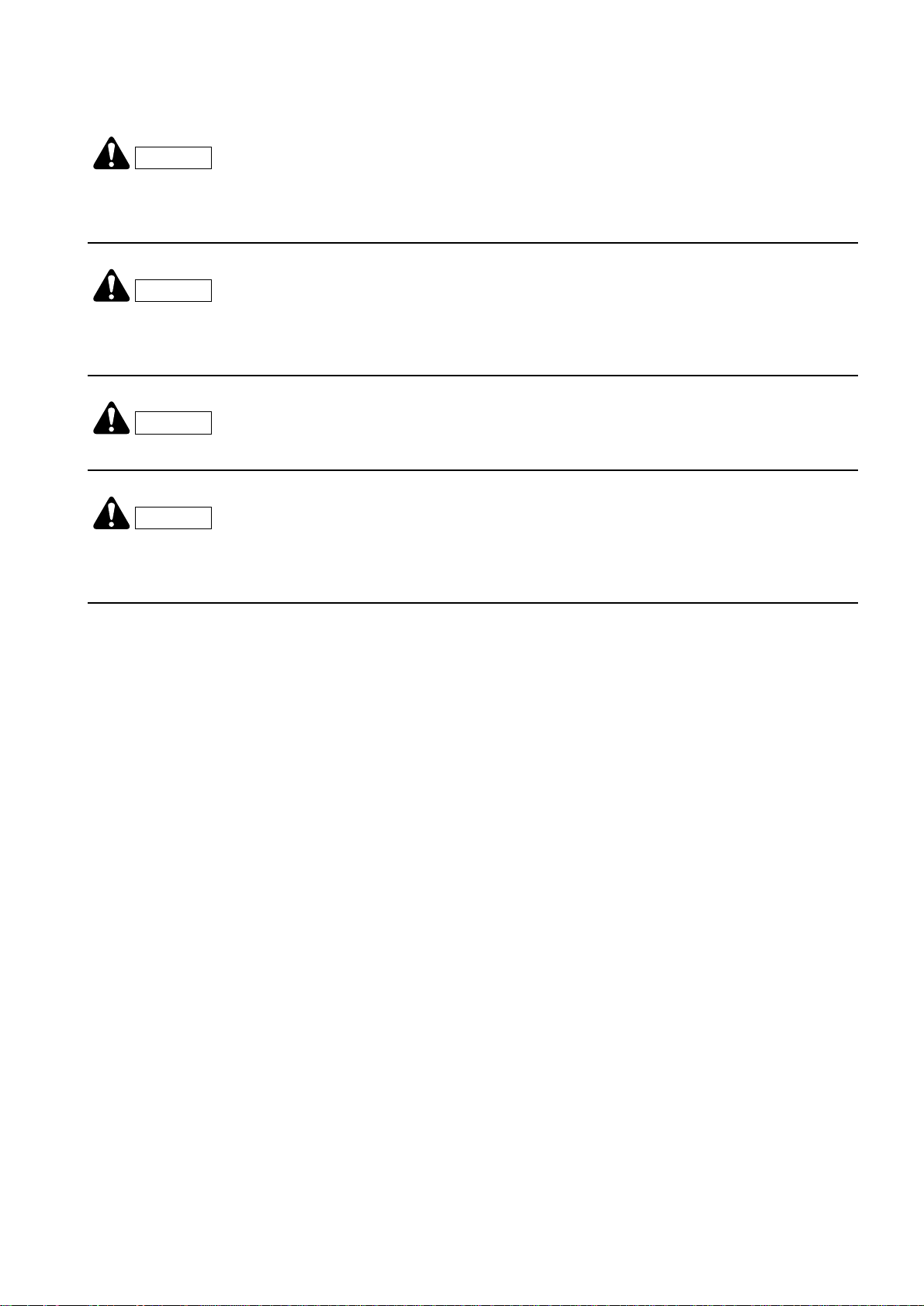
1.4.3 ENGINE SERIAL NUMBER AND EXHAUST GAS EMISSION PLATE
The engine serial number is stam ped on the pl ate posi tioned on
the rear side of the tappet cover.
The plate regardin g the exhaust emission r egulations is applied
to the front side of the tappet cover.
PRODUCT IDENTIFICATION
RWAB0480
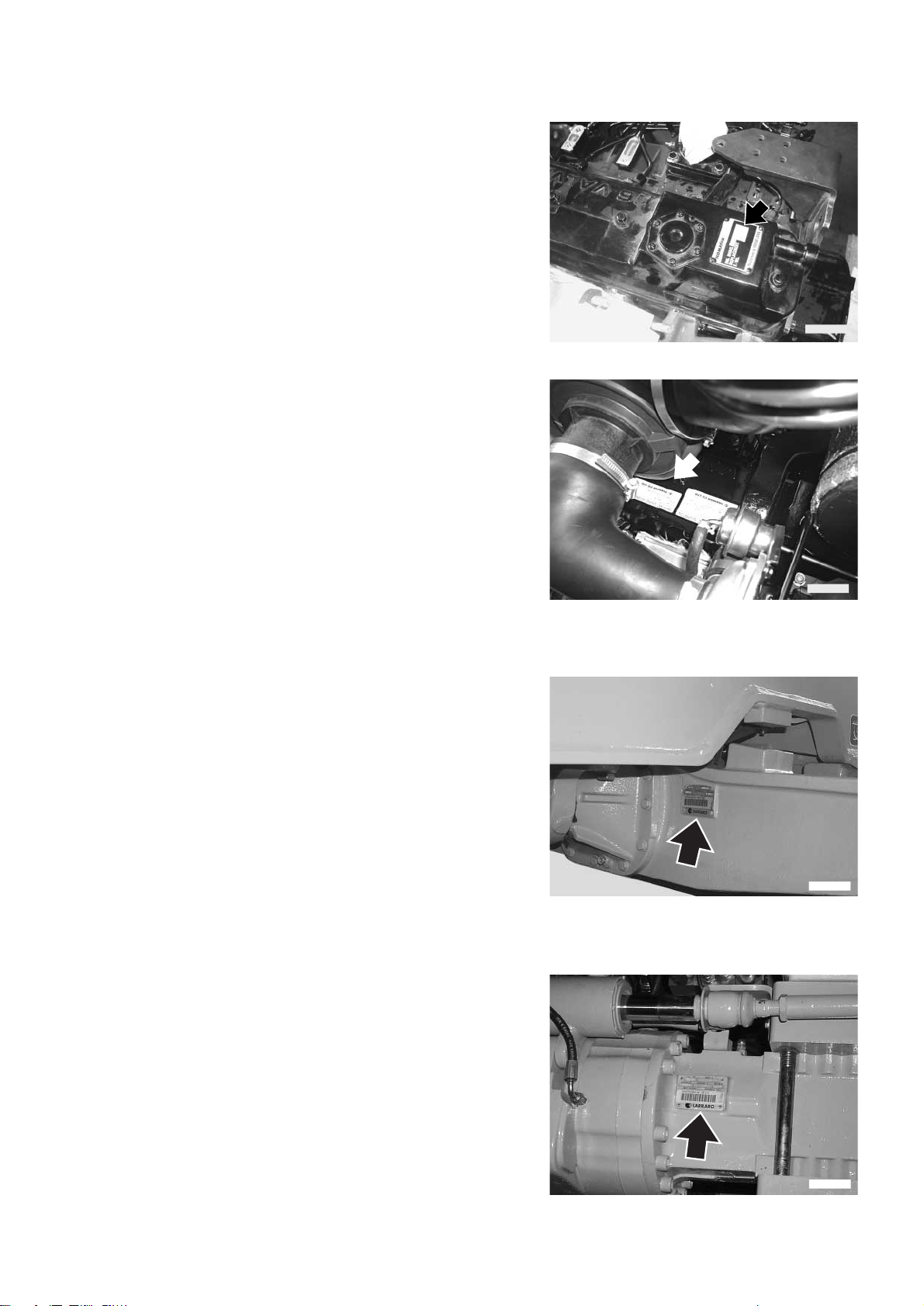
1.4.4 FRONT AXLE SERIAL NUMBER
The serial number of the fro nt axle is st amp ed on the plate positioned on the right side of the axle body.
1.4.5 REAR AXLE SERIAL NUMBER
The serial number o f the rear axle i s sta mped on the pl ate pos itioned on the left side of the axle body.
RWAB0620
RWAA8910
RWAA8920
7
Page 10
PRODUCT IDENTIFICATION
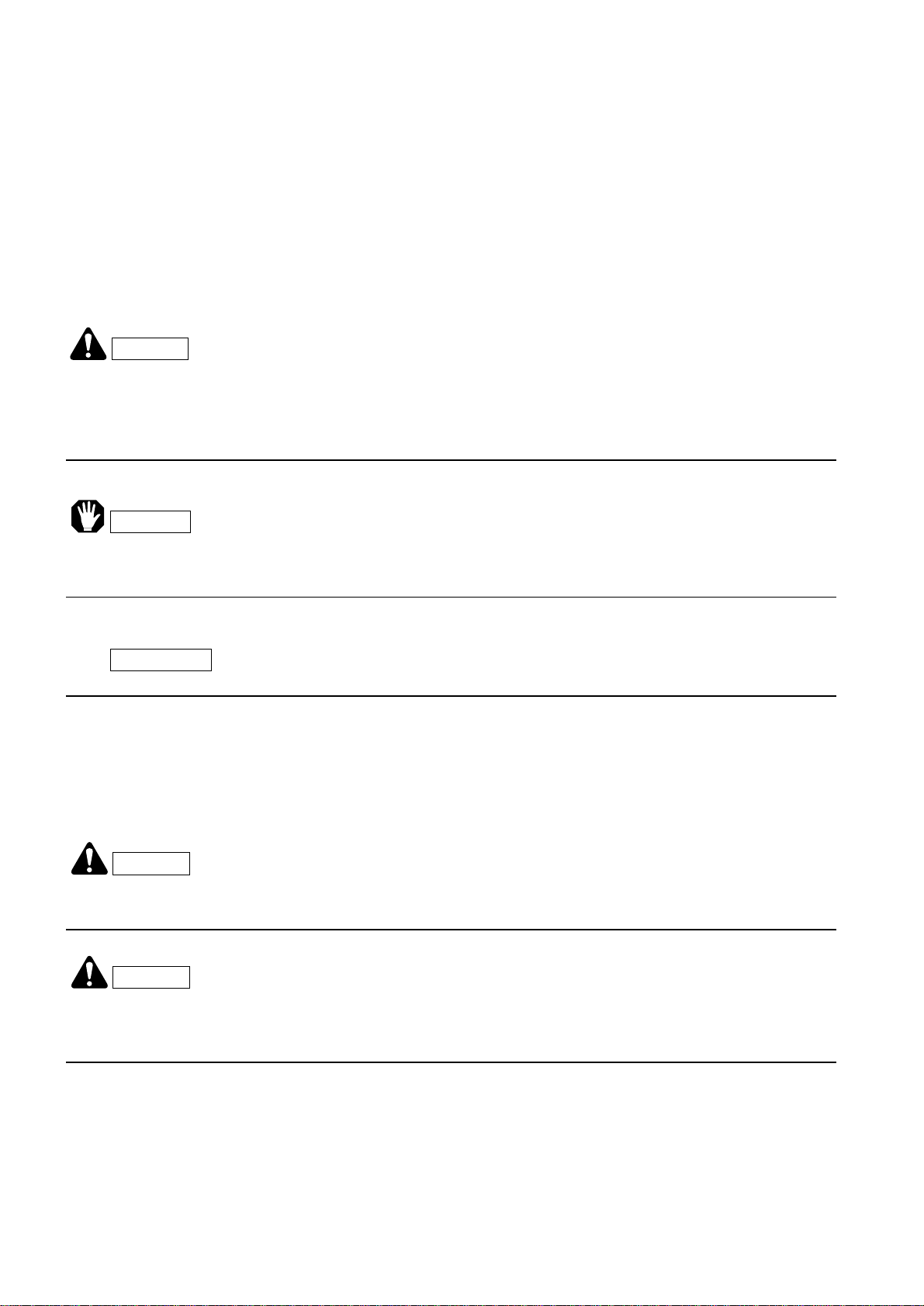
1.4.6 TRANSMISSION SERIAL NUMBER
The transmission serial number is stamped on the plate postioned on the right side of the transmission case.
RWA02540
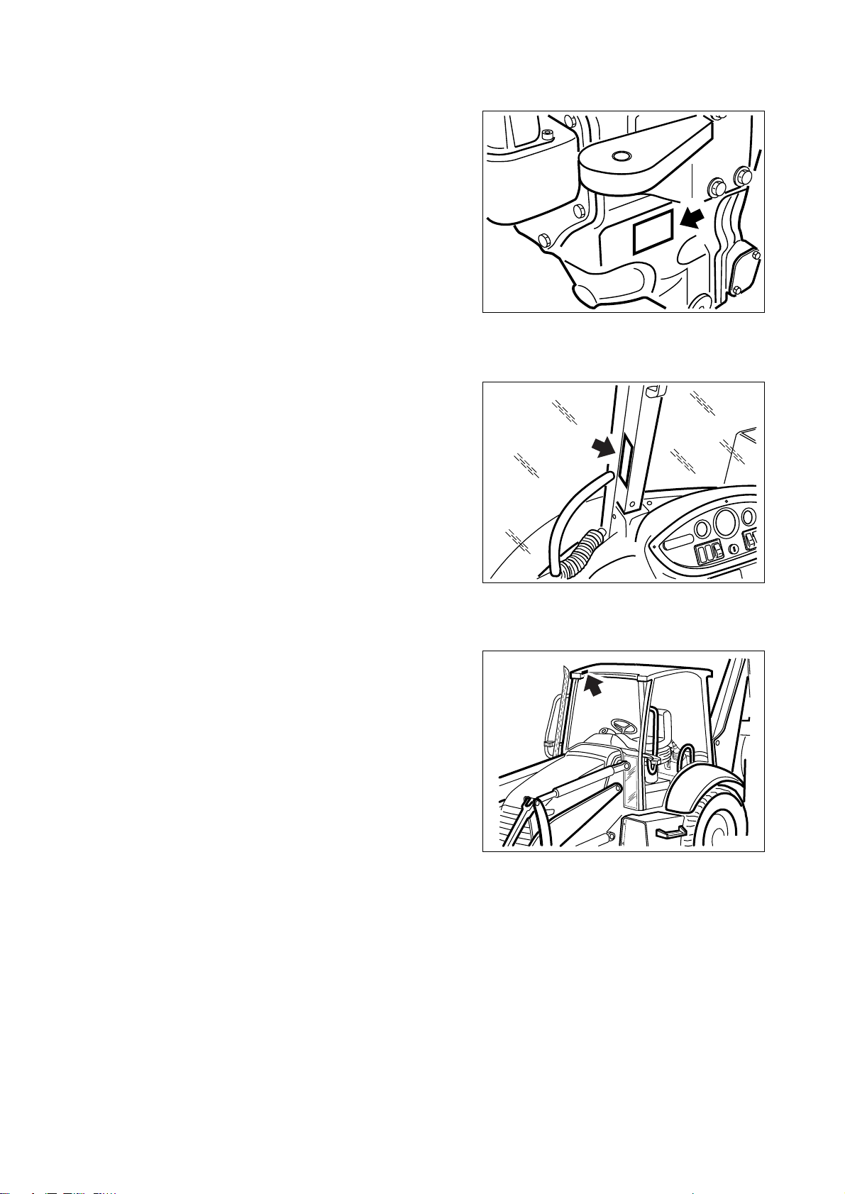
1.4.7 CAB SERIAL NUMBER
The cab serial number is stamped on the plate positioned on the
right center pillar.
1.4.8 CANOPY SERIAL NUMBER (if provided)
The serial number is stam ped on the plate po sitioned inside the
canopy, on the front right part.
RWA02500
RWA18190
8
Page 11

1.4.9 SERIAL NUMBERS AND DEALER’S ADDRESS
Machine n. Model
Engine n.
Front axle n.
Rear axle n.
Transmission n.
Cab n.
Canopy n.
Dealer:
PRODUCT IDENTIFICATION
Address:
Person to contact:
NOTES:
Tel.
9
Page 12

THIS PAGE WAS INTENTIONALLY LEFT EMPTY
10
Page 13

TABLE OF CONTENTS
Page
TABLE OF CONTENTS
1.1 FOREWORD. . . . . . . . . . . . . . . . . . . . . . . . . . . . . . . . . . . . . . . . . . . . . . . . . . . . . . . . . . . . . . . . . . . . 1
1.2 INFORMATION ON SAFETY . . . . . . . . . . . . . . . . . . . . . . . . . . . . . . . . . . . . . . . . . . . . . . . . . . . . . . . 2
1.3 INTRODUCTION. . . . . . . . . . . . . . . . . . . . . . . . . . . . . . . . . . . . . . . . . . . . . . . . . . . . . . . . . . . . . . . . . 4
1.3.1 INTENDED USES . . . . . . . . . . . . . . . . . . . . . . . . . . . . . . . . . . . . . . . . . . . . . . . . . . . . . . . . . 4
1.3.2 IMPROPER OR UNAUTHORIZED USES . . . . . . . . . . . . . . . . . . . . . . . . . . . . . . . . . . . . . . 4
1.3.3 MAIN CHARACTERISTICS . . . . . . . . . . . . . . . . . . . . . . . . . . . . . . . . . . . . . . . . . . . . . . . . . 5
1.3.4 RUNNING-IN . . . . . . . . . . . . . . . . . . . . . . . . . . . . . . . . . . . . . . . . . . . . . . . . . . . . . . . . . . . . . 5
1.4 PRODUCT IDENTIFICATION . . . . . . . . . . . . . . . . . . . . . . . . . . . . . . . . . . . . . . . . . . . . . . . . . . . . . . 6
1.4.1 MACHINE SERIAL NUMBER . . . . . . . . . . . . . . . . . . . . . . . . . . . . . . . . . . . . . . . . . . . . . . . . 6
1.4.2 MACHINE IDENTIFICATION PLATE . . . . . . . . . . . . . . . . . . . . . . . . . . . . . . . . . . . . . . . . . 6
1.4.3 ENGINE SERIAL NUMBER AND EXHAUST GAS EMISSION PLATE. . . . . . . . . . . . . . . . . 7
1.4.4 FRONT AXLE SERIAL NUMBER . . . . . . . . . . . . . . . . . . . . . . . . . . . . . . . . . . . . . . . . . . . . . 7
1.4.5 REAR AXLE SERIAL NUMBER . . . . . . . . . . . . . . . . . . . . . . . . . . . . . . . . . . . . . . . . . . . . . . 8
1.4.6 TRANSMISSION SERIAL NUMBER . . . . . . . . . . . . . . . . . . . . . . . . . . . . . . . . . . . . . . . . . . . 8
1.4.7 CAB SERIAL NUMBER . . . . . . . . . . . . . . . . . . . . . . . . . . . . . . . . . . . . . . . . . . . . . . . . . . . . 8
1.4.8 CANOPY SERIAL NUMBER (if provided) . . . . . . . . . . . . . . . . . . . . . . . . . . . . . . . . . . . . . . 8
1.4.9 SERIAL NUMBERS AND DEALER’S ADDRESS . . . . . . . . . . . . . . . . . . . . . . . . . . . . . . . . . 9
SAFETY AND ACCIDENT PREVENTION
2.1 SAFETY, NOISE AND VIBRATION PLATES . . . . . . . . . . . . . . . . . . . . . . . . . . . . . . . . . . . . . . . . . . 20
2.1.1 POSITION OF THE SAFETY PLATES . . . . . . . . . . . . . . . . . . . . . . . . . . . . . . . . . . . . . . . . . 20
2.1.2 PICTOGRAMS AND RELEVANT MEANINGS . . . . . . . . . . . . . . . . . . . . . . . . . . . . . . . . . . . 22
2.1.3 POSITION OF THE NOISE PLATES ON MACHINES WITH CAB . . . . . . . . . . . . . . . . . . . . 26
2.1.4 VIBRATIONS TO WHICH THE OPERATOR IS SUBJECTED . . . . . . . . . . . . . . . . . . . . . . . 27
2.2 GENERAL PRECAUTIONS . . . . . . . . . . . . . . . . . . . . . . . . . . . . . . . . . . . . . . . . . . . . . . . . . . . . . . . . 28
2.2.1 GENERAL SAFETY RULES . . . . . . . . . . . . . . . . . . . . . . . . . . . . . . . . . . . . . . . . . . . . . . . . . 28
2.2.2 SAFETY DEVICES AND GUARDS. . . . . . . . . . . . . . . . . . . . . . . . . . . . . . . . . . . . . . . . . . . . 28
2.2.3 CLOTHING AND PERSONAL PROTECTION ITEMS. . . . . . . . . . . . . . . . . . . . . . . . . . . . . . 28
2.2.4 UNAUTHORIZED MODIFICATIONS . . . . . . . . . . . . . . . . . . . . . . . . . . . . . . . . . . . . . . . . . . 29
2.2.5 LEAVING THE OPERATOR’S SEAT . . . . . . . . . . . . . . . . . . . . . . . . . . . . . . . . . . . . . . . . . . 29
2.2.6 GETTING ON AND OFF THE MACHINE . . . . . . . . . . . . . . . . . . . . . . . . . . . . . . . . . . . . . . . 30
2.2.7 CHECKING THE REAR-VIEW MIRRORS . . . . . . . . . . . . . . . . . . . . . . . . . . . . . . . . . . . . . . 30
2.2.8 PREVENTING FIRES DUE TO FUEL AND OIL . . . . . . . . . . . . . . . . . . . . . . . . . . . . . . . . . . 30
2.2.9 PREVENTING BURNS . . . . . . . . . . . . . . . . . . . . . . . . . . . . . . . . . . . . . . . . . . . . . . . . . . . . . 31
2.2.10 PREVENTING DAMAGE DUE TO ASBESTOS POWDER. . . . . . . . . . . . . . . . . . . . . . . . . . 31
2.2.11 PREVENTING DAMAGE CAUSED BY THE WORK EQUIPMENT . . . . . . . . . . . . . . . . . . . 32
2.2.12 FIRE EXTINGUISHERS AND FIRST AID KIT. . . . . . . . . . . . . . . . . . . . . . . . . . . . . . . . . . . . 32
2.2.13 PRECAUTIONS CONCERNING THE CAB STRUCTURE . . . . . . . . . . . . . . . . . . . . . . . . . . 32
2.2.14 PRECAUTIONS CONCERNING THE EQUIPMENT. . . . . . . . . . . . . . . . . . . . . . . . . . . . . . . 32
2.3 PRECAUTIONS TO BE TAKEN BEFORE STARTING THE ENGINE . . . . . . . . . . . . . . . . . . . . . . . 33
2.3.1 SAFETY ON THE WORK SITE . . . . . . . . . . . . . . . . . . . . . . . . . . . . . . . . . . . . . . . . . . . . . . . 33
2.3.2 FIRE PREVENTION . . . . . . . . . . . . . . . . . . . . . . . . . . . . . . . . . . . . . . . . . . . . . . . . . . . . . . . 33
2.3.3 PRECAUTIONS TO BE TAKEN FOR THE OPERATOR'S CAB. . . . . . . . . . . . . . . . . . . . . . 33
2.3.4 ROOM VENTILATION . . . . . . . . . . . . . . . . . . . . . . . . . . . . . . . . . . . . . . . . . . . . . . . . . . . . . 34
2.3.5 CLEANING WINDOWS, MIRRORS AND LIGHTS - CHECKING THE WINDSHIELD
WIPER BLADES AND THE BULBS . . . . . . . . . . . . . . . . . . . . . . . . . . . . . . . . . . . . . . . . . . . 34
11
Page 14

TABLE OF CONTENTS
Page
2.4 PRECAUTIONS TO BE TAKEN WHEN WORKING . . . . . . . . . . . . . . . . . . . . . . . . . . . . . . . . . . . . . 35
2.4.1 STARTING THE ENGINE . . . . . . . . . . . . . . . . . . . . . . . . . . . . . . . . . . . . . . . . . . . . . . . . . . . 35
2.4.2 RULES FOR ROAD TRAVEL . . . . . . . . . . . . . . . . . . . . . . . . . . . . . . . . . . . . . . . . . . . . . . . . 35
2.4.3 CHECKS FOR TRAVELLING IN REVERSE . . . . . . . . . . . . . . . . . . . . . . . . . . . . . . . . . . . . 36
2.4.4 MOVING THE MACHINE . . . . . . . . . . . . . . . . . . . . . . . . . . . . . . . . . . . . . . . . . . . . . . . . . . . 36
2.4.5 WORKING ON SLOPES . . . . . . . . . . . . . . . . . . . . . . . . . . . . . . . . . . . . . . . . . . . . . . . . . . . . 37
2.4.6 PREVENTING ELECTROCUTION . . . . . . . . . . . . . . . . . . . . . . . . . . . . . . . . . . . . . . . . . . . . 38
2.4.7 VISIBILITY . . . . . . . . . . . . . . . . . . . . . . . . . . . . . . . . . . . . . . . . . . . . . . . . . . . . . . . . . . . . . . 39
2.4.8 WORKING ON ICY OR SNOW-COVERED SURFACES . . . . . . . . . . . . . . . . . . . . . . . . . . . 39
2.4.9 PREVENTING DAMAGE CAUSED BY THE WORK EQUIPMENT. . . . . . . . . . . . . . . . . . . . 39
2.4.10 WORKING ON LOOSE GROUND. . . . . . . . . . . . . . . . . . . . . . . . . . . . . . . . . . . . . . . . . . . . . 39
2.4.11 PARKING THE MACHINE . . . . . . . . . . . . . . . . . . . . . . . . . . . . . . . . . . . . . . . . . . . . . . . . . . 40
2.5 TRANSPORTING THE MACHINE ON OTHER VEHICLES . . . . . . . . . . . . . . . . . . . . . . . . . . . . . . . 41
2.5.1 LOADING AND UNLOADING THE MACHINE . . . . . . . . . . . . . . . . . . . . . . . . . . . . . . . . . . . 41
2.5.2 THE ROUTE . . . . . . . . . . . . . . . . . . . . . . . . . . . . . . . . . . . . . . . . . . . . . . . . . . . . . . . . . . . . 41
2.6 BATTERY . . . . . . . . . . . . . . . . . . . . . . . . . . . . . . . . . . . . . . . . . . . . . . . . . . . . . . . . . . . . . . . . . . . . . 42
2.6.1 SAFETY PRECAUTIONS FOR WORK ON BATTERIES . . . . . . . . . . . . . . . . . . . . . . . . . . . 42
2.6.2 STARTING WITH BOOSTER CABLES. . . . . . . . . . . . . . . . . . . . . . . . . . . . . . . . . . . . . . . . . 42
2.7 PRECAUTIONS FOR EMERGENCY RECOVERY . . . . . . . . . . . . . . . . . . . . . . . . . . . . . . . . . . . . . . 43
2.8 PRECAUTIONS TO BE TAKEN DURING MAINTENANCE . . . . . . . . . . . . . . . . . . . . . . . . . . . . . . . 44
2.8.1 WARNING PLATES . . . . . . . . . . . . . . . . . . . . . . . . . . . . . . . . . . . . . . . . . . . . . . . . . . . . . . . 44
2.8.2 TOOLS . . . . . . . . . . . . . . . . . . . . . . . . . . . . . . . . . . . . . . . . . . . . . . . . . . . . . . . . . . . . . . . . . 44
2.8.3 PERSONNEL . . . . . . . . . . . . . . . . . . . . . . . . . . . . . . . . . . . . . . . . . . . . . . . . . . . . . . . . . . . . 44
2.8.4 EQUIPMENT . . . . . . . . . . . . . . . . . . . . . . . . . . . . . . . . . . . . . . . . . . . . . . . . . . . . . . . . . . . . . 45
2.8.5 WORKING UNDER THE MACHINE . . . . . . . . . . . . . . . . . . . . . . . . . . . . . . . . . . . . . . . . . . . 45
2.8.6 KEEPING THE MACHINE CLEAN . . . . . . . . . . . . . . . . . . . . . . . . . . . . . . . . . . . . . . . . . . . 45
2.8.7 USE OF THE ENGINE DURING MAINTENANCE . . . . . . . . . . . . . . . . . . . . . . . . . . . . . . . . 46
2.8.8 PERIODICAL CHANGE OF THE PARTS THAT ARE CRITICAL FOR SAFETY . . . . . . . . . 46
2.8.9 STOP THE ENGINE BEFORE CARRYING OUT ANY MAINTENANCE OPERATION
OR INSPECTION . . . . . . . . . . . . . . . . . . . . . . . . . . . . . . . . . . . . . . . . . . . . . . . . . . . . . . . . . 47
2.8.10 RULES FOR REFUELLING AND ADDING OIL . . . . . . . . . . . . . . . . . . . . . . . . . . . . . . . . . . 48
2.8.11 CHECKING THE COOLANT LEVEL IN THE RADIATOR . . . . . . . . . . . . . . . . . . . . . . . . . . 48
2.8.12 USING LAMPS . . . . . . . . . . . . . . . . . . . . . . . . . . . . . . . . . . . . . . . . . . . . . . . . . . . . . . . . . . . 48
2.8.13 PRECAUTIONS CONCERNING THE BATTERY AND THE ALTERNATOR . . . . . . . . . . . . 49
2.8.14 PRECAUTIONS CONCERNING THE STARTER . . . . . . . . . . . . . . . . . . . . . . . . . . . . . . . . 49
2.8.15 PRECAUTIONS CONCERNING THE GEARSHIFT . . . . . . . . . . . . . . . . . . . . . . . . . . . . . . 50
2.8.16 HANDLING HIGH-PRESSURE PIPES . . . . . . . . . . . . . . . . . . . . . . . . . . . . . . . . . . . . . . . . . 50
2.8.17 PRECAUTIONS TO BE TAKEN WHEN HANDLING HIGH-PRESSURE OIL . . . . . . . . . . . 50
2.8.18 PRECAUTIONS FOR MAINTENANCE WORK INVOLVING HIGH TEMPERATURES
AND PRESSURES . . . . . . . . . . . . . . . . . . . . . . . . . . . . . . . . . . . . . . . . . . . . . . . . . . . . . . . . 51
2.8.19 COOLING FAN AND FAN BELT . . . . . . . . . . . . . . . . . . . . . . . . . . . . . . . . . . . . . . . . . . . . . . 51
2.8.20 WASTE MATERIALS. . . . . . . . . . . . . . . . . . . . . . . . . . . . . . . . . . . . . . . . . . . . . . . . . . . . . . . 51
2.8.21 PRECAUTIONS TO BE TAKEN WHEN INFLATING TYRES . . . . . . . . . . . . . . . . . . . . . . . . 52
2.8.22 PRECAUTIONS FOR THE INSTALLATION OF THE EXHAUST SYSTEM TAILPIPE. . . . . 52
2.8.23 PRECAU TIONS FOR THE USE OF THE SYNTHE TIC BIODEGRADABLE OIL
TYPE HEES . . . . . . . . . . . . . . . . . . . . . . . . . . . . . . . . . . . . . . . . . . . . . . . . . . . . . . . . . . . . . 53
12
Page 15

TABLE OF CONTENTS
Page
DESCRIPTION AND USE OF THE MACHINE
3.1 SAFETY LOCKS. . . . . . . . . . . . . . . . . . . . . . . . . . . . . . . . . . . . . . . . . . . . . . . . . . . . . . . . . . . . . . . . . 56
3.1.1 FRONT LOADER LOCKS . . . . . . . . . . . . . . . . . . . . . . . . . . . . . . . . . . . . . . . . . . . . . . . . . . . 56
3.1.2 BACKHOE LOCKS . . . . . . . . . . . . . . . . . . . . . . . . . . . . . . . . . . . . . . . . . . . . . . . . . . . . . . . . 58
3.2 GENERAL VIEWS . . . . . . . . . . . . . . . . . . . . . . . . . . . . . . . . . . . . . . . . . . . . . . . . . . . . . . . . . . . . . . . 59
3.2.1 FRONT GENERAL VIEW . . . . . . . . . . . . . . . . . . . . . . . . . . . . . . . . . . . . . . . . . . . . . . . . . . 59
3.2.2 BACKHOE GENERAL VIEW. . . . . . . . . . . . . . . . . . . . . . . . . . . . . . . . . . . . . . . . . . . . . . . . . 60
3.2.3 CAB INSIDE GENERAL VIEW . . . . . . . . . . . . . . . . . . . . . . . . . . . . . . . . . . . . . . . . . . . . . . . 61
3.2.3.1 CAB INSIDE GENERAL VIEW (Standard version) . . . . . . . . . . . . . . . . . . . . . . 61
3.2.3.2 CAB INSIDE GENERAL VIEW (Version with servcontrols available on request) 62
3.3 INSTRUMENTS AND CONTROLS . . . . . . . . . . . . . . . . . . . . . . . . . . . . . . . . . . . . . . . . . . . . . . . . . . 63
3.3.1 FRONT INSTRUMENTS . . . . . . . . . . . . . . . . . . . . . . . . . . . . . . . . . . . . . . . . . . . . . . . . . . . . 63
3.3.2 SIDE INSTRUMENTS . . . . . . . . . . . . . . . . . . . . . . . . . . . . . . . . . . . . . . . . . . . . . . . . . . . . . . 75
3.3.2.1 SIDE INSTRUMENTS (Standard version) . . . . . . . . . . . . . . . . . . . . . . . . . . . . . . 75
3.3.2.2 SIDE INSTRUMENTS (Version with servo controls available on request) . . . . . 76
3.3.3 PUSH BUTTONS ON THE FRONT LOADER CONTROL LEVER . . . . . . . . . . . . . . . . . . . . 84
3.3.4 ELECTRICAL ACCESSORIES . . . . . . . . . . . . . . . . . . . . . . . . . . . . . . . . . . . . . . . . . . . . . . . 85
3.3.5 MACHINE CONTROLS . . . . . . . . . . . . . . . . . . . . . . . . . . . . . . . . . . . . . . . . . . . . . . . . . . . . . 86
3.3.5.1 MACHINE CONTROLS (Standard version) . . . . . . . . . . . . . . . . . . . . . . . . . . . . . 86
3.3.5.2 MACHINE CONTROLS (Version with servo controls available upon request) . . 87
3.4 FUSES AND RELAYS . . . . . . . . . . . . . . . . . . . . . . . . . . . . . . . . . . . . . . . . . . . . . . . . . . . . . . . . . . . . 127
3.4.1 EQUIPMENT FUSES AND RELAYS. . . . . . . . . . . . . . . . . . . . . . . . . . . . . . . . . . . . . . . . . . . 127
3.4.1.1 FUSES . . . . . . . . . . . . . . . . . . . . . . . . . . . . . . . . . . . . . . . . . . . . . . . . . . . . . . . . . 128
3.4.1.2 RELAYS . . . . . . . . . . . . . . . . . . . . . . . . . . . . . . . . . . . . . . . . . . . . . . . . . . . . . . . 129
3.4.2 ENGINE LINE FUSES AND RELAYS . . . . . . . . . . . . . . . . . . . . . . . . . . . . . . . . . . . . . . . . . . 129
3.4.2.1 FUSES . . . . . . . . . . . . . . . . . . . . . . . . . . . . . . . . . . . . . . . . . . . . . . . . . . . . . . . . . 130
3.4.2.2 RELAYS . . . . . . . . . . . . . . . . . . . . . . . . . . . . . . . . . . . . . . . . . . . . . . . . . . . . . . . 130
3.4.3 SIDE DASHBOARD RELAYS . . . . . . . . . . . . . . . . . . . . . . . . . . . . . . . . . . . . . . . . . . . . . . . . 131
3.4.4 SIDE DASHBOARD RELAYS AND FUSES (Only with servo controls) . . . . . . . . . . . . . . . . 131
3.4.4.1 RELAYS . . . . . . . . . . . . . . . . . . . . . . . . . . . . . . . . . . . . . . . . . . . . . . . . . . . . . . . . 131
3.4.4.2 FUSES . . . . . . . . . . . . . . . . . . . . . . . . . . . . . . . . . . . . . . . . . . . . . . . . . . . . . . . . . 131
3.5 GUARDS, CAB AND DRIVER’S SEAT . . . . . . . . . . . . . . . . . . . . . . . . . . . . . . . . . . . . . . . . . . . . . . . 132
3.5.1 ENGINE HOOD . . . . . . . . . . . . . . . . . . . . . . . . . . . . . . . . . . . . . . . . . . . . . . . . . . . . . . . . . . 132
3.5.2 CANOPY (if provided) . . . . . . . . . . . . . . . . . . . . . . . . . . . . . . . . . . . . . . . . . . . . . . . . . . . . . . 132
3.5.3 CAB . . . . . . . . . . . . . . . . . . . . . . . . . . . . . . . . . . . . . . . . . . . . . . . . . . . . . . . . . . . . . . . . . . . . 133
3.5.4 VENTILATION AND HEATING . . . . . . . . . . . . . . . . . . . . . . . . . . . . . . . . . . . . . . . . . . . . . . . 136
3.5.5 AIR CONDITIONER (if installed) . . . . . . . . . . . . . . . . . . . . . . . . . . . . . . . . . . . . . . . . . . . . . . 137
3.5.6 SEAT . . . . . . . . . . . . . . . . . . . . . . . . . . . . . . . . . . . . . . . . . . . . . . . . . . . . . . . . . . . . . . . . . . . 139
3.5.6.1 SEAT (STANDARD) . . . . . . . . . . . . . . . . . . . . . . . . . . . . . . . . . . . . . . . . . . . . . . 139
3.5.6.2 SEAT (OPTIONAL) . . . . . . . . . . . . . . . . . . . . . . . . . . . . . . . . . . . . . . . . . . . . . . . 140
3.5.7 SAFETY BELT . . . . . . . . . . . . . . . . . . . . . . . . . . . . . . . . . . . . . . . . . . . . . . . . . . . . . . . . . . . 141
3.5.8 FIRE EXTINGUISHER. . . . . . . . . . . . . . . . . . . . . . . . . . . . . . . . . . . . . . . . . . . . . . . . . . . . . . 141
3.5.9 FIRST AID KIT. . . . . . . . . . . . . . . . . . . . . . . . . . . . . . . . . . . . . . . . . . . . . . . . . . . . . . . . . . . . 141
3.5.10 TECHNICAL DOCUMENTATION . . . . . . . . . . . . . . . . . . . . . . . . . . . . . . . . . . . . . . . . . . . . . 141
3.5.11 ADDITIONAL TOOL BOX (if provided) . . . . . . . . . . . . . . . . . . . . . . . . . . . . . . . . . . . . . . . . . 142
3.6 USE OF THE MACHINE. . . . . . . . . . . . . . . . . . . . . . . . . . . . . . . . . . . . . . . . . . . . . . . . . . . . . . . . . . . 143
3.6.1 CHECKS BEFORE STARTING THE ENGINE . . . . . . . . . . . . . . . . . . . . . . . . . . . . . . . . . . . 143
3.6.1.1 VISUAL CHECKS . . . . . . . . . . . . . . . . . . . . . . . . . . . . . . . . . . . . . . . . . . . . . . . . 143
3.6.1.2 DAILY CHECKS . . . . . . . . . . . . . . . . . . . . . . . . . . . . . . . . . . . . . . . . . . . . . . . . . 143
3.6.1.3 OPERATIONAL CHECKS . . . . . . . . . . . . . . . . . . . . . . . . . . . . . . . . . . . . . . . . . . 144
13
Page 16

TABLE OF CONTENTS
Page
3.6.2 STARTING THE ENGINE . . . . . . . . . . . . . . . . . . . . . . . . . . . . . . . . . . . . . . . . . . . . . . . . . . . 145
3.6.2.1 STARTING WITH WARM ENGINE OR IN TEMPERATE CLIMATES . . . . . . . . 145
3.6.2.2 STARTING WITH COLD ENGINE OR IN COLD CLIMATES . . . . . . . . . . . . . . . 146
3.6.3 WARMING THE ENGINE . . . . . . . . . . . . . . . . . . . . . . . . . . . . . . . . . . . . . . . . . . . . . . . . . . . 147
3.6.4 HEATING THE HYDRAULIC OIL . . . . . . . . . . . . . . . . . . . . . . . . . . . . . . . . . . . . . . . . . . . . . 147
3.6.5 HOW TO MOVE THE MACHINE . . . . . . . . . . . . . . . . . . . . . . . . . . . . . . . . . . . . . . . . . . . . . 148
3.6.5.1 ENGAGING THE FOUR-WHEEL DRIVE . . . . . . . . . . . . . . . . . . . . . . . . . . . . . . 149
3.6.5.2 MOVING ON SLOPES. . . . . . . . . . . . . . . . . . . . . . . . . . . . . . . . . . . . . . . . . . . . . 150
3.6.5.3 MAXIMUM IMMERSION DEPTH . . . . . . . . . . . . . . . . . . . . . . . . . . . . . . . . . . . . 151
3.7 PARKING THE MACHINE . . . . . . . . . . . . . . . . . . . . . . . . . . . . . . . . . . . . . . . . . . . . . . . . . . . . . . . . . 152
3.7.1 PARKING ON LEVEL GROUND . . . . . . . . . . . . . . . . . . . . . . . . . . . . . . . . . . . . . . . . . . . . . 152
3.7.2 PARKING ON SLOPES . . . . . . . . . . . . . . . . . . . . . . . . . . . . . . . . . . . . . . . . . . . . . . . . . . . . 153
3.8 STOPPING THE ENGINE. . . . . . . . . . . . . . . . . . . . . . . . . . . . . . . . . . . . . . . . . . . . . . . . . . . . . . . . . . 154
3.9 TRANSPORTING THE MACHINE ON OTHER VEHICLES. . . . . . . . . . . . . . . . . . . . . . . . . . . . . . . . 155
3.9.1 LOADING AND UNLOADING THE MACHINE . . . . . . . . . . . . . . . . . . . . . . . . . . . . . . . . . . . 155
3.9.2 TRANSPORT . . . . . . . . . . . . . . . . . . . . . . . . . . . . . . . . . . . . . . . . . . . . . . . . . . . . . . . . . . . . 156
3.10 PRECAUTIONS TO BE TAKEN IN THE COLD SEASON . . . . . . . . . . . . . . . . . . . . . . . . . . . . . . . . 157
3.10.1 FUEL AND LUBRICANTS . . . . . . . . . . . . . . . . . . . . . . . . . . . . . . . . . . . . . . . . . . . . . . . . . . 157
3.10.2 COOLANT . . . . . . . . . . . . . . . . . . . . . . . . . . . . . . . . . . . . . . . . . . . . . . . . . . . . . . . . . . . . . . . 157
3.10.3 BATTERY . . . . . . . . . . . . . . . . . . . . . . . . . . . . . . . . . . . . . . . . . . . . . . . . . . . . . . . . . . . . . . . 157
3.10.4 OTHER PRECAUTIONS . . . . . . . . . . . . . . . . . . . . . . . . . . . . . . . . . . . . . . . . . . . . . . . . . . . . 158
3.10.5 PRECAUTIONS TO BE TAKEN AT THE END OF WORK . . . . . . . . . . . . . . . . . . . . . . . . . . 158
3.11 PRECAUTIONS TO BE TAKEN IN THE WARM SEASON . . . . . . . . . . . . . . . . . . . . . . . . . . . . . . . 159
3.12 USING THE MACHINE AS A LOADER . . . . . . . . . . . . . . . . . . . . . . . . . . . . . . . . . . . . . . . . . . . . . . . 160
3.12.1 BUCKET POSITION INDICATOR . . . . . . . . . . . . . . . . . . . . . . . . . . . . . . . . . . . . . . . . . . . . . 160
3.12.2 ORGANIZING THE WORK AREA . . . . . . . . . . . . . . . . . . . . . . . . . . . . . . . . . . . . . . . . . . . . 160
3.12.2.1 LOADING HEAPED AND LEVEL MATERIAL . . . . . . . . . . . . . . . . . . . . . . . . . . . 161
3.12.2.2 LOADING OPERATIONS ON SLOPES . . . . . . . . . . . . . . . . . . . . . . . . . . . . . . . 162
3.12.3 CHANGING THE STANDARD FRONT BUCKET . . . . . . . . . . . . . . . . . . . . . . . . . . . . . . . . . 162
3.13 USING THE MACHINE AS AN EXCAVATOR . . . . . . . . . . . . . . . . . . . . . . . . . . . . . . . . . . . . . . . . . . 163
3.13.1 POSITIONING THE BUCKET ACCORDING TO THE WORK TO BE CARRIED OUT. . . . . 163
3.13.2 POSITIONING THE MACHINE FOR DIGGING OPERATIONS . . . . . . . . . . . . . . . . . . . . . . 164
3.13.3 SLIDING THE BACKHOE UNIT SIDEWARDS . . . . . . . . . . . . . . . . . . . . . . . . . . . . . . . . . . . 165
3.13.4 DIGGING METHOD . . . . . . . . . . . . . . . . . . . . . . . . . . . . . . . . . . . . . . . . . . . . . . . . . . . . . . . 166
3.13.5 CHANGING THE BACKHOE BUCKET . . . . . . . . . . . . . . . . . . . . . . . . . . . . . . . . . . . . . . . . 167
3.14 LONG PERIODS OF INACTIVITY . . . . . . . . . . . . . . . . . . . . . . . . . . . . . . . . . . . . . . . . . . . . . . . . . . . 168
3.14.1 BEFORE THE PERIOD OF INACTIVITY . . . . . . . . . . . . . . . . . . . . . . . . . . . . . . . . . . . . . . . 168
3.14.2 DURING THE PERIOD OF INACTIVITY . . . . . . . . . . . . . . . . . . . . . . . . . . . . . . . . . . . . . . . 170
3.14.3 AFTER THE PERIOD OF INACTIVITY . . . . . . . . . . . . . . . . . . . . . . . . . . . . . . . . . . . . . . . . . 170
3.15 TROUBLESHOOTING . . . . . . . . . . . . . . . . . . . . . . . . . . . . . . . . . . . . . . . . . . . . . . . . . . . . . . . . . . . . 171
3.15.1 HOW TO REMOVE THE MACHINE . . . . . . . . . . . . . . . . . . . . . . . . . . . . . . . . . . . . . . . . . . . 171
3.15.2 IF THE FUEL HAS BEEN COMPLETELY DEPLETED. . . . . . . . . . . . . . . . . . . . . . . . . . . . . 171
3.15.3 IF THE BATTERY IS DEPLETED . . . . . . . . . . . . . . . . . . . . . . . . . . . . . . . . . . . . . . . . . . . . 172
3.15.3.1 STARTING WITH BOOSTER CABLES . . . . . . . . . . . . . . . . . . . . . . . . . . . . . . . . 173
3.15.4 OTHER TROUBLES . . . . . . . . . . . . . . . . . . . . . . . . . . . . . . . . . . . . . . . . . . . . . . . . . . . . . . 174
3.15.4.1 ELECTRICAL CIRCUIT . . . . . . . . . . . . . . . . . . . . . . . . . . . . . . . . . . . . . . . . . . . . 174
3.15.4.2 HYDRAULIC SYSTEM . . . . . . . . . . . . . . . . . . . . . . . . . . . . . . . . . . . . . . . . . . . . 174
3.15.4.3 BRAKING SYSTEM . . . . . . . . . . . . . . . . . . . . . . . . . . . . . . . . . . . . . . . . . . . . . . . 175
3.15.4.4 CONVERTER . . . . . . . . . . . . . . . . . . . . . . . . . . . . . . . . . . . . . . . . . . . . . . . . . . . 175
3.15.4.5 ENGINE . . . . . . . . . . . . . . . . . . . . . . . . . . . . . . . . . . . . . . . . . . . . . . . . . . . . . . . . 176
14
Page 17

TABLE OF CONTENTS
Page
MAINTENANCE
4.1 GUIDE TO MAINTENANCE . . . . . . . . . . . . . . . . . . . . . . . . . . . . . . . . . . . . . . . . . . . . . . . . . . . . . . . . 178
4.2 MAINTENANCE NOTES . . . . . . . . . . . . . . . . . . . . . . . . . . . . . . . . . . . . . . . . . . . . . . . . . . . . . . . . . . 180
4.2.1 NOTES REGARDING THE ENGINE . . . . . . . . . . . . . . . . . . . . . . . . . . . . . . . . . . . . . . . . . . 180
4.2.1.1 ENGINE OIL . . . . . . . . . . . . . . . . . . . . . . . . . . . . . . . . . . . . . . . . . . . . . . . . . . . . 180
4.2.1.2 COOLANT . . . . . . . . . . . . . . . . . . . . . . . . . . . . . . . . . . . . . . . . . . . . . . . . . . . . . . 180
4.2.1.3 FUEL . . . . . . . . . . . . . . . . . . . . . . . . . . . . . . . . . . . . . . . . . . . . . . . . . . . . . . . . . . 181
4.2.2 NOTES REGARDING THE HYDRAULIC SYSTEM . . . . . . . . . . . . . . . . . . . . . . . . . . . . . . . 181
4.2.3 NOTES REGARDING THE ELECTRICAL SYSTEM. . . . . . . . . . . . . . . . . . . . . . . . . . . . . . . 182
4.2.4 NOTES REGARDING LUBRICATION . . . . . . . . . . . . . . . . . . . . . . . . . . . . . . . . . . . . . . . . . 182
4.2.5 PARTS SUBJECT TO WEAR THAT PERIODICALLY NEED CHANGING. . . . . . . . . . . . . . 183
4.3 FUEL, COOLANT AND LUBRICANTS . . . . . . . . . . . . . . . . . . . . . . . . . . . . . . . . . . . . . . . . . . . . . . . 184
4.3.1 HOMOLOGATED HEES SYNTHETIC BIODEGRADABLE LUBRICANTS. . . . . . . . . . . . . . 186
4.4 DRIVING TORQUES FOR SCREWS AND NUTS . . . . . . . . . . . . . . . . . . . . . . . . . . . . . . . . . . . . . . . 187
4.4.1 STANDARD DRIVING TORQUES . . . . . . . . . . . . . . . . . . . . . . . . . . . . . . . . . . . . . . . . . . . . 187
4.4.2 SPECIFIC DRIVING TORQUES . . . . . . . . . . . . . . . . . . . . . . . . . . . . . . . . . . . . . . . . . . . . . . 187
4.5 LUBRICATION . . . . . . . . . . . . . . . . . . . . . . . . . . . . . . . . . . . . . . . . . . . . . . . . . . . . . . . . . . . . . . . . . . 188
4.5.1 LUBRICATION DIAGRAM . . . . . . . . . . . . . . . . . . . . . . . . . . . . . . . . . . . . . . . . . . . . . . . . . . 188
4.5.2 LUBRICATION DIAGRAM (4in1 bucket and pallet forks) . . . . . . . . . . . . . . . . . . . . . . . . . . . 189
4.5.3 LUBRICATION DIAGRAM (Front bucket rapid couplings) . . . . . . . . . . . . . . . . . . . . . . . . . . 190
4.5.4 LUBRICATION DIAGRAM (Telescopic arm) . . . . . . . . . . . . . . . . . . . . . . . . . . . . . . . . . . . . . 191
4.5.5 LUBRICATION DIAGRAM (Offset device). . . . . . . . . . . . . . . . . . . . . . . . . . . . . . . . . . . . . . . 192
4.6 PERIODICAL CHANGE OF THE COMPONENTS CONNECTED WITH SAFETY . . . . . . . . . . . . . . 193
4.6.1 CRITICAL PARTS FOR SAFETY . . . . . . . . . . . . . . . . . . . . . . . . . . . . . . . . . . . . . . . . . . . . . 194
4.7 MAINTENANCE PLAN . . . . . . . . . . . . . . . . . . . . . . . . . . . . . . . . . . . . . . . . . . . . . . . . . . . . . . . . . . . 198
4.7.1 WHEN REQUIRED . . . . . . . . . . . . . . . . . . . . . . . . . . . . . . . . . . . . . . . . . . . . . . . . . . . . . . . . 202
4.7.1.a CHECKING, CLEANING OR CHANGING THE AIR CLEANER CARTRIDGE . . 202
4.7.1.b CHECKING AND CLEANING THE CAB AIR FILTER . . . . . . . . . . . . . . . . . . . . . 203
4.7.1.c CHECKING AND CLEANING THE RECIRCULATING AIR FILTER
(only for machines with air conditioner) . . . . . . . . . . . . . . . . . . . . . . . . . . . . . . . . 204
4.7.1.d BLEEDING THE BRAKING CIRCUIT . . . . . . . . . . . . . . . . . . . . . . . . . . . . . . . . . 205
4.7.1.e CLEANING THE WATER SEPARATOR . . . . . . . . . . . . . . . . . . . . . . . . . . . . . . . 206
4.7.1.f CHECKING AND ADJUSTING THE WHEEL TOE-IN . . . . . . . . . . . . . . . . . . . . . 206
4.7.1.g CHECKING AND ADJUSTING THE PARKING BRAKE . . . . . . . . . . . . . . . . . . . 207
4.7.1.h CHECKING THE BRAKING EFFICIENCY . . . . . . . . . . . . . . . . . . . . . . . . . . . . . 208
4.7.1.j CHECKING AND ADJUSTING THE BRAKE PEDAL STROKE. . . . . . . . . . . . . . 209
4.7.1.k ADJUSTING THE AUTOMATIC RETURN-TO-DIG DEVICE
OF THE FRONT BUCKET (if installed) . . . . . . . . . . . . . . . . . . . . . . . . . . . . . . . . 209
4.7.1.l CHECKING AND ADJUSTING THE STABILIZER SLACK . . . . . . . . . . . . . . . . . 210
4.7.2 MAINTENANCE INTERVALS IN CASE OF USE OF THE DEMOLITION HAMMER . . . . . . 211
4.7.2.a CHANGING THE HYDRAULIC OIL FILTER . . . . . . . . . . . . . . . . . . . . . . . . . . . . 211
4.7.2.b CHANGING THE HYDRAULIC OIL . . . . . . . . . . . . . . . . . . . . . . . . . . . . . . . . . . . 211
4.7.3 CHECKS BEFORE STARTING . . . . . . . . . . . . . . . . . . . . . . . . . . . . . . . . . . . . . . . . . . . . . . 212
4.7.3.a VARIOUS CHECKS . . . . . . . . . . . . . . . . . . . . . . . . . . . . . . . . . . . . . . . . . . . . . . . 212
4.7.3.b CHECKING THE COOLANT LEVEL . . . . . . . . . . . . . . . . . . . . . . . . . . . . . . . . . . 212
4.7.3.c CHECKING THE FUEL LEVEL . . . . . . . . . . . . . . . . . . . . . . . . . . . . . . . . . . . . . . 213
4.7.3.d CHECKING THE ENGINE OIL LEVEL. . . . . . . . . . . . . . . . . . . . . . . . . . . . . . . . . 213
4.7.3.e CHECKING THE HYDRAULIC CIRCUIT OIL LEVEL . . . . . . . . . . . . . . . . . . . . . 214
4.7.3.f DRAINING THE WATER SEPARATOR. . . . . . . . . . . . . . . . . . . . . . . . . . . . . . . . 215
4.7.4 MAINTENANCE EVERY 10 HOURS OF OPERATION . . . . . . . . . . . . . . . . . . . . . . . . . . . . 216
4.7.4.a LUBRICATING THE JOINTS . . . . . . . . . . . . . . . . . . . . . . . . . . . . . . . . . . . . . . . . 216
15
Page 18

TABLE OF CONTENTS
4.7.5 MAINTENANCE AFTER THE FIRST 50 HOURS OF OPERATION
(Only for machines in which the synthetic biodegradable oil type HEES is used) . . . . . . . . . 218
4.7.6 MAINTENANCE EVERY 50 HOURS OF OPERATION . . . . . . . . . . . . . . . . . . . . . . . . . . . . 218
4.7.6.a CHECKING THE RADIATOR FLUID LEVEL . . . . . . . . . . . . . . . . . . . . . . . . . . . . 218
4.7.6.b CHECKING THE BRAKING SYSTEM OIL LEVEL. . . . . . . . . . . . . . . . . . . . . . . . 218
4.7.6.c LUBRICATING THE PROPELLER SHAFTS . . . . . . . . . . . . . . . . . . . . . . . . . . . . 219
4.7.6.d LUBRICATING THE FRONT AXLE JOINTS AND CENTRAL COUPLING
AND THE REAR AXLE JOINTS. . . . . . . . . . . . . . . . . . . . . . . . . . . . . . . . . . . . . . 220
4.7.6.e CHECKING THE TYRE PRESSURE . . . . . . . . . . . . . . . . . . . . . . . . . . . . . . . . . 220
4.7.6.f CHECKING THE ELECTRICAL SYSTEM . . . . . . . . . . . . . . . . . . . . . . . . . . . . . . 221
4.7.7 MAINTENANCE AFTER THE FIRST 250 HOURS OF OPERATION . . . . . . . . . . . . . . . . . . 222
4.7.8 MAINTENANCE EVERY 250 HOURS OF OPERATION . . . . . . . . . . . . . . . . . . . . . . . . . . . 223
4.7.8.a ADJUSTING THE FAN BELT TENSION . . . . . . . . . . . . . . . . . . . . . . . . . . . . . . . 223
4.7.8.b ADJUSTING THE A/C COMPRESSOR BELT TENSION
(Only for machines with air conditioner) . . . . . . . . . . . . . . . . . . . . . . . . . . . . . . . 224
4.7.8.c CHECKING THE BATTERY ELECTROLYTE LEVEL . . . . . . . . . . . . . . . . . . . . . 225
4.7.8.d CHECKING THE FRONT AXLE OIL LEVELS . . . . . . . . . . . . . . . . . . . . . . . . . . . 226
4.7.8.e CHECKING THE REAR AXLE OIL LEVELS . . . . . . . . . . . . . . . . . . . . . . . . . . . . 226
4.7.8.f CHECKING THE HYDRAULIC TRANSMISSION OIL LEVEL . . . . . . . . . . . . . . . 227
4.7.8.g CHECKING THE WHEEL NUT DRIVING TORQUE . . . . . . . . . . . . . . . . . . . . . . 227
4.7.9 MAINTENANCE AFTER THE FIRST 500 HOURS OF OPERATION
(Only for machines in which the synthetic biodegradable oil type HEES is used) . . . . . . . . . 228
4.7.10 MAINTENANCE EVERY 500 HOURS OF OPERATION . . . . . . . . . . . . . . . . . . . . . . . . . . . 229
4.7.10.a CHANGING THE ENGINE OIL. . . . . . . . . . . . . . . . . . . . . . . . . . . . . . . . . . . . . . . 229
4.7.10.b CHANGING THE ENGINE OIL FILTER . . . . . . . . . . . . . . . . . . . . . . . . . . . . . . . 230
4.7.10.c CHANGING THE HYDRAULIC SYSTEM OIL FILTER . . . . . . . . . . . . . . . . . . . . 230
4.7.10.d CHANGING THE FUEL FILTER. . . . . . . . . . . . . . . . . . . . . . . . . . . . . . . . . . . . . . 233
4.7.10.e DRAINING THE FUEL TANK . . . . . . . . . . . . . . . . . . . . . . . . . . . . . . . . . . . . . . . 234
4.7.10.f DRAINING THE HYDRAULIC OIL TANK
(Only for machines in which the synthetic biodegradable oil type HEES is used) 235
4.7.10.g CLEANING THE OUTSIDE OF THE RADIATORS . . . . . . . . . . . . . . . . . . . . . . . 236
4.7.10.h CLEANING THE OUTSIDE OF THE A/C CONDENSER
(Only for machines with air conditioner) . . . . . . . . . . . . . . . . . . . . . . . . . . . . . . . 237
4.7.11 MAINTENANCE EVERY 1000 HOURS OF OPERATION . . . . . . . . . . . . . . . . . . . . . . . . . . 238
4.7.11.a CHANGING THE FRONT AXLE OIL . . . . . . . . . . . . . . . . . . . . . . . . . . . . . . . . . . 238
4.7.11.b CHANGING THE REAR AXLE OIL . . . . . . . . . . . . . . . . . . . . . . . . . . . . . . . . . . . 239
4.7.11.c CHANGING THE HYDRAULIC TRANSMISSION OIL . . . . . . . . . . . . . . . . . . . . . 240
4.7.11.d CHANGING THE HYDRAULIC TRANSMISSION FILTER. . . . . . . . . . . . . . . . . . 241
4.7.11.e CHECKING AND ADJUSTING THE ENGINE VALVE CLEARANCE . . . . . . . . . 241
4.7.12 MAINTENANCE EVERY 2000 HOURS OF OPERATION . . . . . . . . . . . . . . . . . . . . . . . . . . 242
4.7.12.a CHANGING THE HYDRAULIC SYSTEM OIL AND CLEANING THE SUCTION
FILTER . . . . . . . . . . . . . . . . . . . . . . . . . . . . . . . . . . . . . . . . . . . . . . . . . . . . . . . . 242
4.7.12.b CHANGING THE COOLANT . . . . . . . . . . . . . . . . . . . . . . . . . . . . . . . . . . . . . . . 244
4.7.12.c CHANGING THE BRAKING SYSTEM OIL . . . . . . . . . . . . . . . . . . . . . . . . . . . . . 246
4.7.12.d CHECKING THE ALTERNATOR AND THE STARTER . . . . . . . . . . . . . . . . . . . 246
4.7.12.e CHECKING THE QUANTITY OF COOLANT IN THE A/C SYSTEM
(Only for machines with air conditioner) . . . . . . . . . . . . . . . . . . . . . . . . . . . . . . . 247
4.7.13 MAINTENANCE EVERY 4000 HOURS OF OPERATION . . . . . . . . . . . . . . . . . . . . . . . . . . 248
4.7.13.a CHANGING THE A/C DEHYDRATING FILTER
(Only for machines with air conditioner) . . . . . . . . . . . . . . . . . . . . . . . . . . . . . . . 248
4.7.13.b CHECKING THE OPERATING CONDITIONS OF THE A/C COMPRESSOR
(Only for machines with air conditioner) . . . . . . . . . . . . . . . . . . . . . . . . . . . . . . . 248
Page
16
Page 19

TABLE OF CONTENTS
Page
TECHNICAL SPECIFICATIONS
5.1 TECHNICAL DATA. . . . . . . . . . . . . . . . . . . . . . . . . . . . . . . . . . . . . . . . . . . . . . . . . . . . . . . . . . . . . . . 250
5.1.1 STANDARD OVERALL DIMENSIONS WITH CENTERED BACKHOE . . . . . . . . . . . . . . . . 250
5.1.2 STANDARD OVERALL DIMENSIONS WITH FOLDED BACKHOE . . . . . . . . . . . . . . . . . . 250
5.1.3 TECHNICAL CHARACTERISTICS . . . . . . . . . . . . . . . . . . . . . . . . . . . . . . . . . . . . . . . . . . . . 251
5.1.4 LIFTING CAPACITIES . . . . . . . . . . . . . . . . . . . . . . . . . . . . . . . . . . . . . . . . . . . . . . . . . . . . . 252
5.1.4.1 SYMBOL TABLE . . . . . . . . . . . . . . . . . . . . . . . . . . . . . . . . . . . . . . . . . . . . . . . . . 252
5.1.4.2 LIFTING CAPACITY (STANDARD BOOM) . . . . . . . . . . . . . . . . . . . . . . . . . . . . . 253
5.1.4.3 LIFTING CAPACITY (OFFSET BOOM) . . . . . . . . . . . . . . . . . . . . . . . . . . . . . . . 254
AUTHORIZED OPTIONAL EQUIPMENT
6.1 AUTHORIZED OPTIONAL EQUIPMENT. . . . . . . . . . . . . . . . . . . . . . . . . . . . . . . . . . . . . . . . . . . . . . 256
6.1.1 CHARACTERISTICS OF THE OPTIONAL EQUIPMENT . . . . . . . . . . . . . . . . . . . . . . . . . . . 256
6.2 FRONT EQUIPMENT QUICK COUPLING DEVICES . . . . . . . . . . . . . . . . . . . . . . . . . . . . . . . . . . . . 257
6.2.1 MANUAL CONTROL QUICK COUPLING. . . . . . . . . . . . . . . . . . . . . . . . . . . . . . . . . . . . . . . 257
6.2.2 HYDRAULIC CONTROL QUICK COUPLING FOR STANDARD BUCKET. . . . . . . . . . . . . . 258
6.2.3 HYDRAULIC CONTROL QUICK COUPLING FOR 4IN1 BUCKET AND OPTIONAL
EQUIPMENT WITH UNIDIRECTIONAL OIL FLOW . . . . . . . . . . . . . . . . . . . . . . . . . . . . . . . 258
6.3 4in1 BUCKET . . . . . . . . . . . . . . . . . . . . . . . . . . . . . . . . . . . . . . . . . . . . . . . . . . . . . . . . . . . . . . . . . . 259
6.3.1 DESCRIPTION AND CONTROLS. . . . . . . . . . . . . . . . . . . . . . . . . . . . . . . . . . . . . . . . . . . . . 259
6.3.2 SAFETY DEVICES . . . . . . . . . . . . . . . . . . . . . . . . . . . . . . . . . . . . . . . . . . . . . . . . . . . . . . . . 259
6.3.3 INSTALLING THE 4in1 BUCKET . . . . . . . . . . . . . . . . . . . . . . . . . . . . . . . . . . . . . . . . . . . . . 260
6.3.4 USING THE 4in1 BUCKET . . . . . . . . . . . . . . . . . . . . . . . . . . . . . . . . . . . . . . . . . . . . . . . . . . 261
6.3.5 MAINTENANCE. . . . . . . . . . . . . . . . . . . . . . . . . . . . . . . . . . . . . . . . . . . . . . . . . . . . . . . . . . . 261
6.4 PALLET FORKS. . . . . . . . . . . . . . . . . . . . . . . . . . . . . . . . . . . . . . . . . . . . . . . . . . . . . . . . . . . . . . . . . 262
6.4.1 DESCRIPTION . . . . . . . . . . . . . . . . . . . . . . . . . . . . . . . . . . . . . . . . . . . . . . . . . . . . . . . . . . . 262
6.4.2 SAFETY DEVICES . . . . . . . . . . . . . . . . . . . . . . . . . . . . . . . . . . . . . . . . . . . . . . . . . . . . . . . . 262
6.4.3 USING THE FORKS . . . . . . . . . . . . . . . . . . . . . . . . . . . . . . . . . . . . . . . . . . . . . . . . . . . . . . . 263
6.4.3.1 PREPARING THE PALLET FORKS FOR USE . . . . . . . . . . . . . . . . . . . . . . . . . 263
6.4.3.2 OVERTURNING THE FORKS FOR TRAVEL ON ROADS . . . . . . . . . . . . . . . . . 264
6.4.4 REMOVING THE FORKS . . . . . . . . . . . . . . . . . . . . . . . . . . . . . . . . . . . . . . . . . . . . . . . . . . . 265
6.4.5 INSTALLING THE FORKS . . . . . . . . . . . . . . . . . . . . . . . . . . . . . . . . . . . . . . . . . . . . . . . . . . 265
6.4.6 MAINTENANCE . . . . . . . . . . . . . . . . . . . . . . . . . . . . . . . . . . . . . . . . . . . . . . . . . . . . . . . . . . 265
6.5 BACKHOE TELESCOPIC ARM . . . . . . . . . . . . . . . . . . . . . . . . . . . . . . . . . . . . . . . . . . . . . . . . . . . . 266
6.5.1 DESCRIPTION AND CONTROL . . . . . . . . . . . . . . . . . . . . . . . . . . . . . . . . . . . . . . . . . . . . . 266
6.5.1.1 VERSION WITH STANDARD CONTROLS . . . . . . . . . . . . . . . . . . . . . . . . . . . . . 266
6.5.1.2 VERSION WITH SERVO CONTROLS (if installed) . . . . . . . . . . . . . . . . . . . . . . . 266
6.5.2 SAFETY DEVICES . . . . . . . . . . . . . . . . . . . . . . . . . . . . . . . . . . . . . . . . . . . . . . . . . . . . . . . . 267
6.5.3 USING THE TELESCOPIC ARM. . . . . . . . . . . . . . . . . . . . . . . . . . . . . . . . . . . . . . . . . . . . . . 267
6.5.4 MAINTENANCE. . . . . . . . . . . . . . . . . . . . . . . . . . . . . . . . . . . . . . . . . . . . . . . . . . . . . . . . . . . 268
6.5.4.1 ADJUSTING THE GUIDE SLACK . . . . . . . . . . . . . . . . . . . . . . . . . . . . . . . . . . . . 268
17
Page 20

TABLE OF CONTENTS
Page
6.6 ARRANGEMENT FOR THE INSTALLATION OF THE DEMOLITION HAMMER . . . . . . . . . . . . . . 270
6.6.1 DESCRIPTION AND CONTROL . . . . . . . . . . . . . . . . . . . . . . . . . . . . . . . . . . . . . . . . . . . . . 270
6.6.1.1 VERSION WITH STANDARD CONTROLS . . . . . . . . . . . . . . . . . . . . . . . . . . . . . 270
6.6.1.2 VERSION WITH SERVO CONTROLS (if installed) . . . . . . . . . . . . . . . . . . . . . . 270
6.6.2 USE OF THE DEMOLITION HAMMER AND RULES TO BE OBSERVED. . . . . . . . . . . . . . 271
6.6.3 INSTALLING AND REMOVING THE DEMOLITION HAMMER . . . . . . . . . . . . . . . . . . . . . . 275
6.6.3.1 INSTALLING THE HAMMER . . . . . . . . . . . . . . . . . . . . . . . . . . . . . . . . . . . . . . . . 275
6.6.3.2 REMOVING THE HAMMER. . . . . . . . . . . . . . . . . . . . . . . . . . . . . . . . . . . . . . . . . 277
6.6.4 USING THE HAMMER . . . . . . . . . . . . . . . . . . . . . . . . . . . . . . . . . . . . . . . . . . . . . . . . . . . . . 277
6.6.5 MAINTENANCE . . . . . . . . . . . . . . . . . . . . . . . . . . . . . . . . . . . . . . . . . . . . . . . . . . . . . . . . . . 277
6.7 APPLICATION OF THE OFFSET DEVICE . . . . . . . . . . . . . . . . . . . . . . . . . . . . . . . . . . . . . . . . . . . . 278
6.7.1 DESCRIPTION AND CONTROL. . . . . . . . . . . . . . . . . . . . . . . . . . . . . . . . . . . . . . . . . . . . . . 278
6.7.1.1 VERSION WITH STANDARD CONTROLS . . . . . . . . . . . . . . . . . . . . . . . . . . . . . 278
6.7.1.2 VERSION WITH SERVO CONTROLS (if installed) . . . . . . . . . . . . . . . . . . . . . . 279
6.7.2 MAINTENANCE. . . . . . . . . . . . . . . . . . . . . . . . . . . . . . . . . . . . . . . . . . . . . . . . . . . . . . . . . . . 279
6.8 ARRANGEMENT FOR THE OPERATION OF OPTIONAL EQUIPMENT WITH UNIDIRECTIONAL
OIL FLOW. . . . . . . . . . . . . . . . . . . . . . . . . . . . . . . . . . . . . . . . . . . . . . . . . . . . . . . . . . . . . . . . . . . . . . 280
6.8.1 DESCRIPTION AND CONTROL. . . . . . . . . . . . . . . . . . . . . . . . . . . . . . . . . . . . . . . . . . . . . . 280
6.8.1.1 VERSION WITH STANDARD CONTROLS . . . . . . . . . . . . . . . . . . . . . . . . . . . . . 280
6.8.1.2 VERSION WITH SERVO CONTROLS (if installed) . . . . . . . . . . . . . . . . . . . . . . 280
6.8.2 INSTALLING AND CONNECTING THE EQUIPMENT . . . . . . . . . . . . . . . . . . . . . . . . . . . . 281
6.8.3 MAINTENANCE. . . . . . . . . . . . . . . . . . . . . . . . . . . . . . . . . . . . . . . . . . . . . . . . . . . . . . . . . . . 281
6.9 ARRANGEMENT FOR THE INSTALLATION OF THE CLAMSHELL BUCKET . . . . . . . . . . . . . . . 282
6.9.1 DESCRIPTION AND CONTROL . . . . . . . . . . . . . . . . . . . . . . . . . . . . . . . . . . . . . . . . . . . . . 282
6.9.1.1 VERSION WITH STANDARD CONTROLS . . . . . . . . . . . . . . . . . . . . . . . . . . . . . 282
6.9.1.2 VERSION WITH SERVO CONTROLS (if installed) . . . . . . . . . . . . . . . . . . . . . . 283
6.9.2 INSTALLING THE CLAMSHELL BUCKET . . . . . . . . . . . . . . . . . . . . . . . . . . . . . . . . . . . . . . 284
6.9.3 USING THE CLAMSHELL BUCKET . . . . . . . . . . . . . . . . . . . . . . . . . . . . . . . . . . . . . . . . . . . 285
6.9.4 MAINTENANCE. . . . . . . . . . . . . . . . . . . . . . . . . . . . . . . . . . . . . . . . . . . . . . . . . . . . . . . . . . . 285
6.10 ARRANGEMENT FOR THE INSTALLATION OF THE MANUAL HYDRAULIC HAMMER . . . . . . . 286
6.10.1 DESCRIPTION AND CONTROL . . . . . . . . . . . . . . . . . . . . . . . . . . . . . . . . . . . . . . . . . . . . . . 286
6.10.2 CONNECTING AND REMOVING THE HAMMER . . . . . . . . . . . . . . . . . . . . . . . . . . . . . . . . 287
6.10.2.1 CONNECTING THE HAMMER . . . . . . . . . . . . . . . . . . . . . . . . . . . . . . . . . . . . . . 287
6.10.2.2 REMOVING THE CONNECTIONS . . . . . . . . . . . . . . . . . . . . . . . . . . . . . . . . . . . 287
6.10.3 USING THE HAMMER . . . . . . . . . . . . . . . . . . . . . . . . . . . . . . . . . . . . . . . . . . . . . . . . . . . . . 288
6.10.4 MAINTENANCE . . . . . . . . . . . . . . . . . . . . . . . . . . . . . . . . . . . . . . . . . . . . . . . . . . . . . . . . . . 288
6.11 LOAD STABILIZER SYSTEM (LSS) (Optional) . . . . . . . . . . . . . . . . . . . . . . . . . . . . . . . . . . . . . . . 289
6.11.1 ACCUMULATOR OF THE LOAD STABILIZER SYSTEM (LSS) . . . . . . . . . . . . . . . . . . . . . 289
6.12 REAR EQUIPMENT RAPID COUPLING DEVICE . . . . . . . . . . . . . . . . . . . . . . . . . . . . . . . . . . . . . . 290
6.12.1 EQUIPMENT COUPLING AND RELEASE PROCEDURE . . . . . . . . . . . . . . . . . . . . . . . . . . 291
6.12.2 MAINTENANCE. . . . . . . . . . . . . . . . . . . . . . . . . . . . . . . . . . . . . . . . . . . . . . . . . . . . . . . . . . . 293
18
Page 21

SAFETY AND
ACCIDENT PREVENTION
Page 22
SAFETY, NOISE AND VIBRATION PLATES
2.1 SAFETY, NOISE AND VIBRATION PLATES
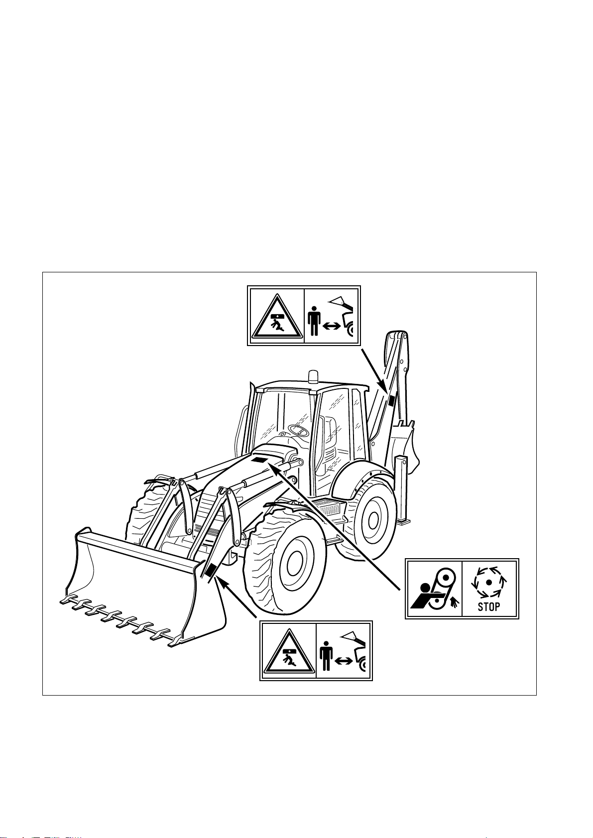
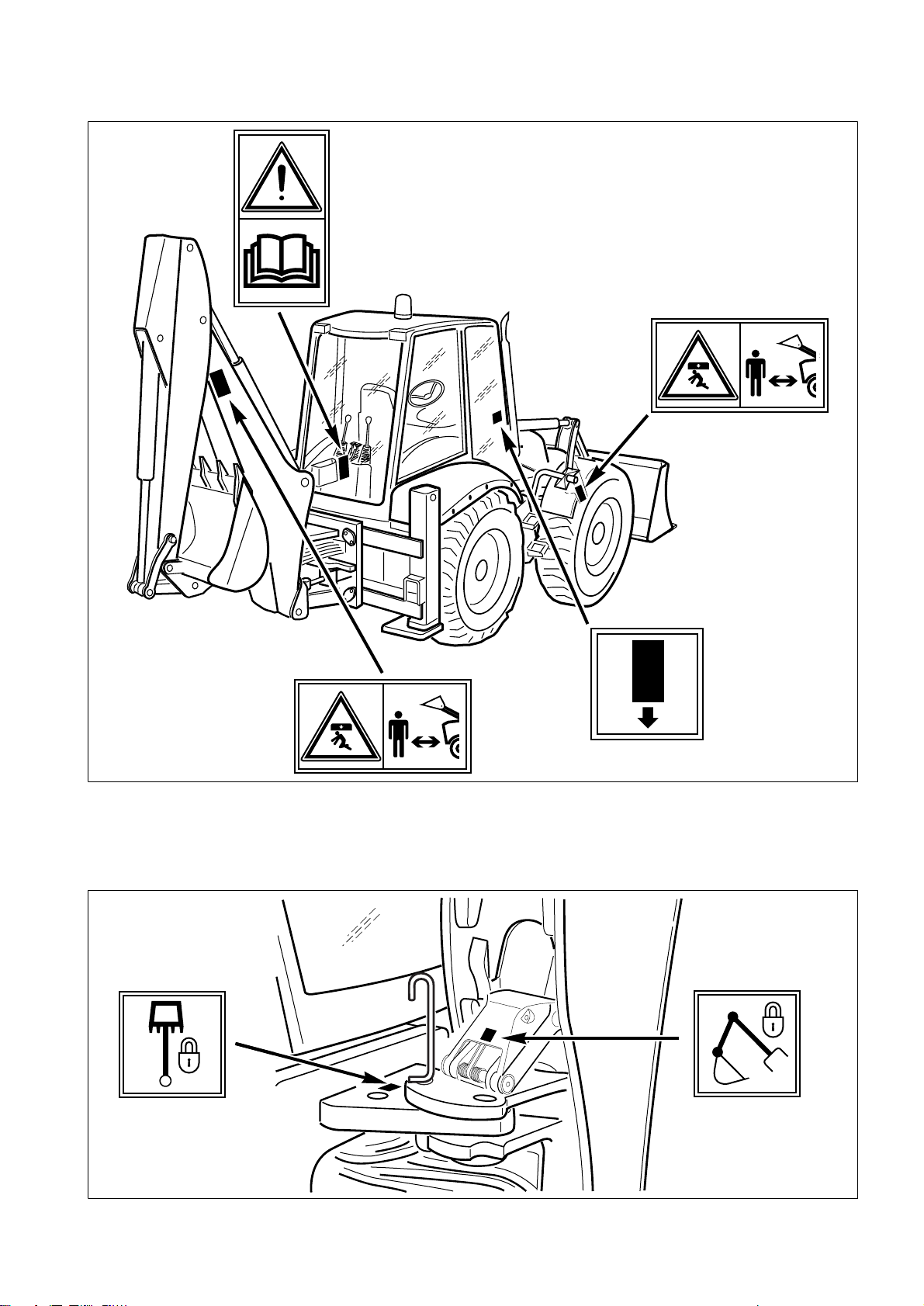
2.1.1 POSITION OF THE SAFETY PLATES
• The safety plates must always be legible and in good conditions; for this reason, if they are dirty with dust, oil or
grease, it is necessary to clean them with a solution made of water and detergent.
Do not use fuel, petrol or solvents.
• If the plates are damaged, ask for new ones to Komatsu Utility or to your Komatsu Utility Dealer.
• In case of replacement of a component provided with a safety plate, make sure that this plate is applied also on
the new piece.
• The machine can be p rovided with other pla tes in addition to those indicated below; keep also to the instr uc-
tions given in the additional plates, in any case.
RWA26140
RWA00020
20
RWA00010
RWA00020
Page 23
RWA26150
SAFETY, NOISE AND VIBRATION PLATES
RWA00030
RWA00020
RWA00150
RWA00190
RWA00020
RWA00160
RWA37700
21
Page 24
SAFETY, NOISE AND VIBRATION PLATES
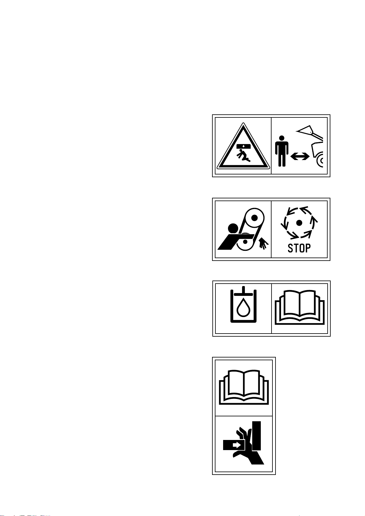
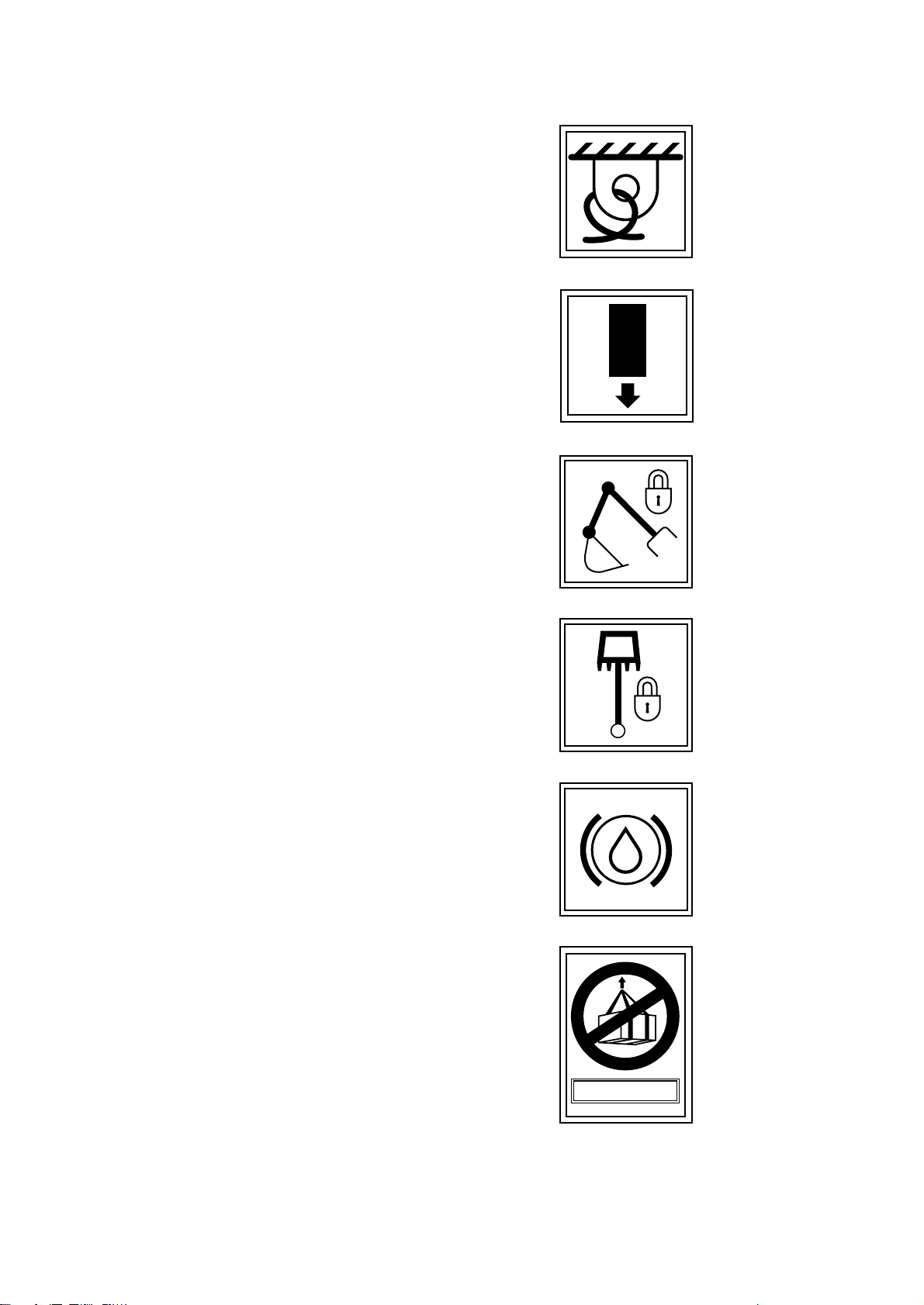
2.1.2 PICTOGRAMS AND RELEVANT MEANINGS
The warning and danger plates applied onto the machine are accompanied or represented by pictograms.
The personnel in charge with the operation and maintenance of the machine must know the symbols contained in
the pictograms perfectly; the following description illustrates what they look like and their respective meanings.
DANGER IN THE WORK AREA
• Do not approach or stand in the equ ipment operating radius
when the boom and the bucket are raised.
RWA00020
DO NOT OPEN THE HOOD
• Do not open or remove the hood when the engine is running.
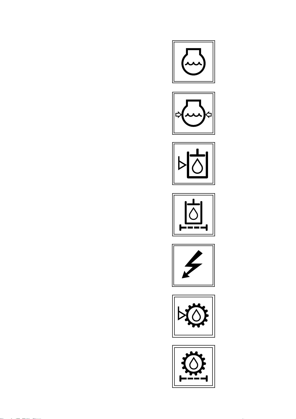
FILLING THE HYDRAULIC SYSTEM WITH
OIL
(Only for machines in which the synthetic biod egr adable oil
type HEES is used)
O VERTURNING THE FORKS
• When the forks are overturned for use or storage, be care-
ful to the grasping points, since hands and feet may be injured and even cut.
BIO-OIL
RWA00010
RWA34380
22
RWA35830
Page 25

CONSULT THE MANUAL
• Carefully read the contents of the manual before using the ma-
chine or performing maintenance operations.
HYDRAULIC OIL TOPPING UP
SAFETY, NOISE AND VIBRATION PLATES
RWA00030
REFUELLING
ENGINE LUBRICATING OIL FILTER
FUEL FILTER
RWA00050
D
RWA00040
RWA00080
D
ENGINE AIR SUCTION FILTER
RWA00060
RWA00090
23
Page 26
SAFETY, NOISE AND VIBRATION PLATES
ENGINE COOLANT
ENGINE COOLANT PRESSURE
HYDRAULIC OIL LEVEL
RWA00130
RWA00110
HYDRAULIC OIL FILTER
ELECTRIC OUTLET
TRANSMISSION OIL LEVEL
RWA00120
RWA00100
RWA00070
12 V
HYDRAULIC TRANSMISSION OIL FILTER
24
RWA00180
RWA00170
Page 27
ANCHORAGE POINT
EMERGENCY EXIT
BOOM LOCK
SAFETY, NOISE AND VIBRATION PLATES
RWA00200
RWA00190
SWING LOCK
BRAKE OIL
DO NOT LIFT MORE THAN 1000 kg
RWA00160
RWA00150
RWA00140
> 1000 Kg
RWA00210
25
Page 28

SAFETY, NOISE AND VIBRATION PLATES
2.1.3 POSITION OF THE NOISE PLATES ON MACHINES WITH CAB
• The noise plates must always be legible and in good conditions; for this reason, if they are dirty with dust, oil or
grease, it is necessary to clean them with a solution made of water and detergent.
Do not use fuel, petrol or solvents.
• If the plates are damaged, ask for new ones to Komatsu Utility or to your Komatsu Utility Dealer.
• In case of replacement of a component provided with a noise plate, make sure that this plate is applied also on
the new piece.
ISO 6396
NOISE OUTSIDE THE CAB
• This value indicates the noise level outside the machine and
refers to the noise perceived by persons in the vicinity of th e
work area.
NOISE INSIDE THE CAB
• This value indicates the maximum noise level perceived by the
operator’s ears inside the cab when this is completely closed.
2000/14/EC
2000/14/EC
RWA37710
RWA37720
26
ISO 6396
RWA37730
Page 29

SAFETY, NOISE AND VIBRATION PLATES
2.1.4 VIBRATIONS TO WHICH THE OPERATOR IS SUBJECTED
• According to the res ults of the test s carried out t o determine the vibrations transmi tted to the operator by the
machine, the upper limbs are subjected to vibrations lower than 2.5 m/sq.sec., while the seated part of the body
is subject to vibrations lower than 0.5 m/sq.sec.
27
Page 30
GENERAL PRECAUTIONS
2.2 GENERAL PRECAUTIONS
2.2.1 GENERAL SAFETY RULES
• Only trained and authorized personnel can use the machine and perform maintenance operations.
• Follow all the safety rules, precautions and instructions when using the machine or performing maintenance op-
erations.
• When working with other op erators or w hen the wor k site is often occup ied by other op erators, make sure that
everyone knows and understands all t he signals described above and, in any cas e, that everyone works in
such a way as to be able to see the machine and to be visible to the operator.
2.2.2 SAFETY DEVICES AND GUARDS
• Make sure that all the g uards and covers are in the correct posit ion. Have guards and covers chang ed or re-
paired if damaged. Neither use the machine without guards, nor rem ove the guards when the engine is running.
• Always use the proper safety devices to lock the machine when parking and fasten the safety belt.
• For the safety devices, see “3.1 SAFETY LOCKS”.
• For the safety belt, see “3.5.7 SAFETY BELT”.
• Do not remove the safety devices and always keep them in good operating conditions.
• Any improper use of the safety devices may result in serious injuries or even death.
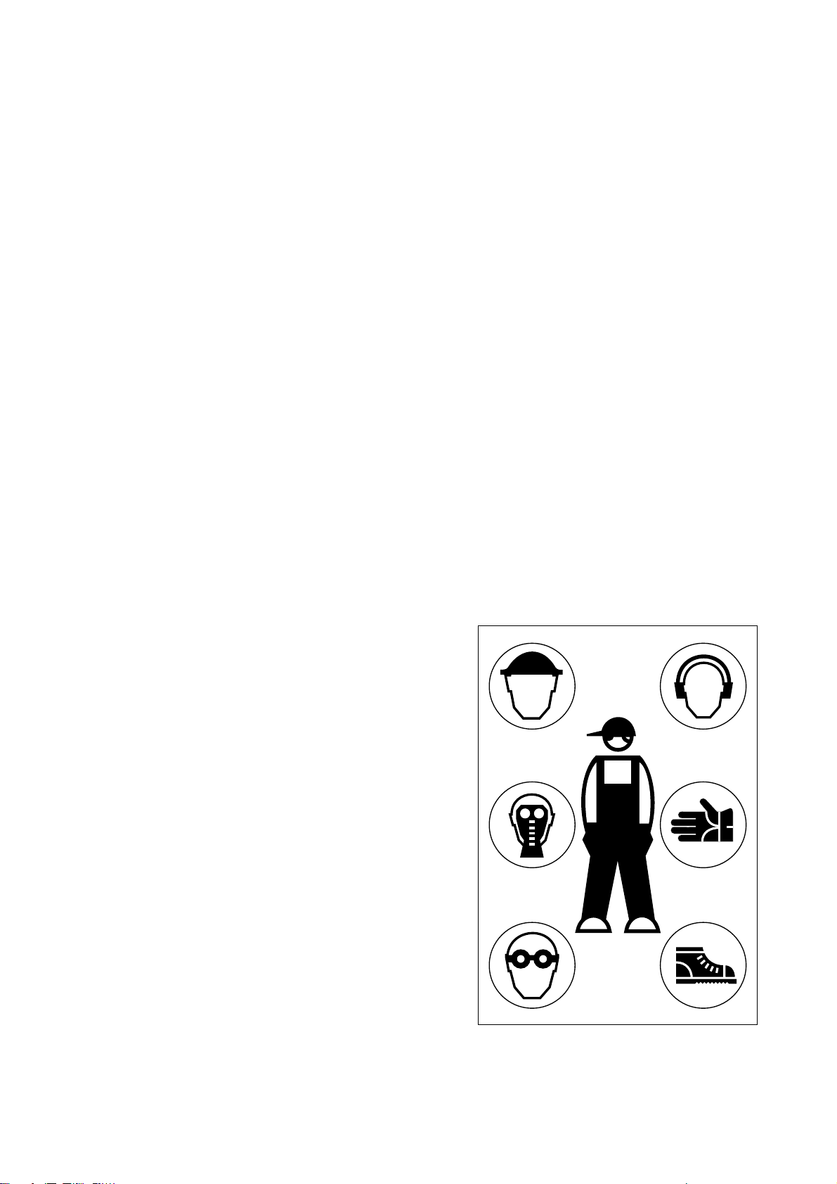
2.2.3 CLOTHING AND PERSONAL PRO-
TECTION ITEMS
• Do not wear large or loos e clothes, ri ngs and watches and d o
not approach the machi ne with lo ose long h air, since they can
get entagled in the moving parts of the machine and cause serious injuries or damage.
Avoid also wearing clothes dir ty with oi l or fuel, since they are
flammable.
• Wear a hard hat, goggles, safety shoes, mask, gloves and
headphones when ope rating the m achine or pe rforming maintenance operations.
• Always wear safety goggles, a hard hat and heavy gloves if
your job involves scattering metal chips or minute materials;
these precautions are particularly useful when driving the
equipment connection pi ns with a hammer and when blowing
compressed air into the air filter and the radiator to clean them.
During these opera tions, make also sure that no one i s sta nding or working near the machine without the necessary protections.
• When working for 8 hours with a noise level exceeding 90
dBA, it is necessar y to use headphones or ear plu gs and be
particularly careful, especially at the end of the work shift.
28
RWA00960
Page 31

GENERAL PRECAUTIONS
IMPORTANT
☞
2.2.4 UNAUTHORIZED MODIFICATIONS
• Any modification made without the authorization of Komatsu Utility can involve hazards.
• Before making a modification, consul t your Komatsu Utility Dealer. Komatsu Utility declines any respo nsibility
for injuries or damage caused by unauthorized modifications.
2.2.5 LEAVING THE OPERATOR’S SEAT
• When leaving the operator’s seat, even if temporarily, make
sure that t h e m ac h ine is in a safe positio n. (See “2.4.11 PARKING THE MACHINE”).
• Before leaving the operator’s seat, carry out the following oper-
ations in the sequence indicated below:
1 - Rest the equipment onto the ground.
2 - Connect the safety devices of the controls.
3 - Apply the parking brake.
4 - Shift the reversing gear lever to the neutral position.
5 - Stop the engine.
RWA31250
• If the machine is equipped with backhoe servo controls,
before leaving the operator seat always engage the control locking safety device by pressing the relevant switch,
see “3.3.5.2 MACHINE CONTROLS (Version with servo
controls)”, pos. 26.
If you have to go so far away that you will not be able to see the
machine, extract the ignition key.
RWA34810
RWA35030
29
Page 32

GENERAL PRECAUTIONS
2.2.6 GETTING ON AND OFF THE MA-
CHINE
• Do not jump on or off the machine, either when it is at rest and
when it is moving.
• When getting on or off the ma chine, always use the handles
and the safety ladders; get on and off t he machine very carefully.
• Never hold or rest on the steering wheel or the gearshift lever.
• Either when getting on and when get ting off the machine, al-
ways maintain three points of contact (holding or resting
points), in order to avoid losing your balance and falling down.
• Tighten the handle and ladder connect ion screws if they are
loose and clean the handl es and steps if they are dirty with oil
or grease.
Carefully clean the cab floor if it is dirty with oil , grease, mud
or rubble.
The cab
RWA25650
Safety canopy
2.2.7 CHECKING THE REAR-VIEW MIR-
RORS
• Make sure that the rear-view mirrors are clean and correcly
positioned; they must allow the opera tor to see the rear of th e
machine with no need to move the chest with respect to the
normal work position.
• If the rear-view mirrors should move or break during work, stop
the machine immediately and fasten or change them.
• Working without checking the back of the machi ne is danger-
ous, since the machine may hit persons who are in cautiously
standing in the wor k area, fixed obstacl es or manoeu vring vehicles.
2.2.8 PREVENTING FIRES DUE TO FUEL
AND OIL
Fuel, oil and some types of antifreeze can be easily ignited if
they get in contact with a flame. Fuel is par ticularly flammable
and therefore extremely hazardous.
• Keep any naked flame away from flammable fluids.
• Stop the engine and do not smoke when refuelling.
• Top up with fu el and oil only after stopping the engine and in
well ventilated areas.
• Top up wi th fuel an d oil in a well deli mited area a nd do not al-
low unauthorized persons to approach.
RWA25760
RWA25860
RWA00970
30
Page 33

• When refuelling, hold the fuel gun firmly and keep it constantly
in contact with the filler until you have finished, in order to
avoid sparks due to static electricity.
• After topping up, tighten the fuel and oil safety caps securely.
• Do not fill the tank completely, in order to leave room for the fu-
el to expand.
• In case some fuel is spilled, wipe it up immediately.
2.2.9 PREVENTING BURNS
• If the engine coolant, the engi ne oil and the hydraulic oil are
hot, use heavy cloths and wear gloves, heavy clothing and
safety goggles before carryi ng out any check or touching the
hot parts.
• Before checking the coolant level, stop the en gine and let the
fluid cool down.
If a check is necessary du e to the overheating of the engine,
slowly loosen the radia tor plug to release any residual pressure before removing it. The hot fluid that spurts out may
cause serious burns.
• Before checking the engine oil and hydraulic circuit oil level,
stop the engine and l et the oil cool down. The hot oil that can
be sprayed out of the tank may cause serious burns.
GENERAL PRECAUTIONS
RWA00980
RWA00990
2.2.10 PREVENTING DAMAGE DUE TO ASBESTOS POWDER
• Asbestos powder can be hazardous to your health if it is in-
haled.
• If you handle materials contai ning asbes tos fib ers, keep to the
instructions given below:
1 - Do not use compressed air, b ut only aspirators to clean the
machine and make sure that the room in which you are
working is properly ventilated.
2 - Use low-pressure water to keep down the dust when clean-
ing.
3 - If there is danger that there may be asbestos powder in the
air, operate the machine with the wind to your back whenever possible.
4 - Even if the cab provides suitable protection, use an ap-
proved and homologated respirator.
5 - The powder gathered during the cleaning operations must
be dampened and put in a sealed and marked container, so
that it can be safely disposed of according to the regulations in force.
RWA01000
RWA01010
31
Page 34

GENERAL PRECAUTIONS
2.2.11 PREVENTING D AMAGE CA USED BY THE WORK EQUIPMENT
• Do not stand within or approach the operating radius of the
work equipment, even when the operator is on board th e machine and the engine is running.
• Do not stand or work unde r the arms or the articul ati ons whe n
the arms are lifted, if you are not sure that the safety locks
have been duly engaged.
• Do not carry out any operation requiring the lifting of the arms,
if you are not sure that the locks are correctly positioned and
coupled to the arms.
2.2.12 FIRE EXTINGUISHERS AND FIRST AID KIT
• Make sure that fire extinguishers have been provided and
check their position.
• Periodically make sure that th e fire extinguishers are loaded
and that you know how to use them.
RWA01020
• Find out where the first aid kit has been located.
• Periodically make sure that the first aid kit conta ins the neces-
sary disinfectants, bandages, medicins, etc.
• It is necessary to know what to do in case of fire.
• Make sure that you have the phone numbers of the persons or
structures you may need to contact in case of an emergency at
hand (either at the wor k site and where maintenance operations are performed).
RWA01030
2.2.13 PRECAUTIONS CONCERNING THE CAB STRUCTURE
• If the cab is inadvertently hit or the machine overturns during work, the cab may be damaged with cons eq uen t
reduction of its stiffness and of the safety that must be guaranteed to the operator (Rops/Fops homologation).
Contact Komatsu Utility or an Authorized Komatsu Utility Dealer to have the cab structure and resistance
checked in case of impact or damage.
2.2.14 PRECAUTIONS CONCERNING THE EQUIPMENT
• When installing and using optional equipment, carefully read the relevant instruction manual and keep to the in-
dications given therein.
• Do not use optional o r special equipment without the authorization of Komatsu Utility or th e Komatsu Utility
Dealer.
The installation and us e of unauthori zed equipment may create safety problems and ad versely affect the efficiency and life of the machine.
• Komatsu Utility cannot be held li able for any injury, accident, product failure resulting fr om the installa tion and
use of unauthorized equipment.
32
Page 35

PRECAUTIONS TO BE TAKEN BEFORE STARTING THE ENGINE
2.3 PRECAUTIONS TO BE TAKEN BEFORE STARTING THE ENGINE
2.3.1 SAFETY ON THE WORK SITE
• Before starting the engine, thoroughly check the area for any
unusual condition of the ground due to which work may be
dangerous.
• Check the conditions of the ground at the work site an d before
starting the engine defin e the work pl an and the best and s afest operating procedure.
• Make the ground surface as level as possible before carr ying
out any operation.
• In case of work on the road, protect pedestr ians and cars by
designating a person for work site traffic duty and install fences
around the work site.
• If water lines, gas lines, and telephone or high-voltage electr i-
cal lines are locate d under the work si te, contact the relevant
utility company in order to find out their exact positions or to
make them inneffective until the end of the operations. Be
careful not to sever or damage any of these lines.
RWA00220
• Check the depth and flow of water before operating in water or
on river banks.
2.3.2 FIRE PREVENTION
• Completely remove all wood chips, r ubbish, paper and other
flammable materials that may hav e accumulated inside the engine compartment, since they can cause fires.
• Check the fuel and hydraulic system pipes for leaks and if nec-
essary repa ir them. Wipe up any excess oil, fuel or other flammable fluids.
• Make sure that fire extinguish ers are available in the work a r-
ea.
RWA01040
2.3.3 PRECAUTIONS TO BE TAKEN FOR THE OPERATOR’S CAB
• Do not leave objects or tools lying a round in the operator ’s cab. They may hinder the operation of the brakes
and cause serious accidents.
• Keep the cab floor and the controls (steer in g wheel and levers) clean, by removing a ny trace of oil an d grease
and, as far as the floor is concerned, remove any excess dirt (earth, stones, etc.).
• Check the safety belt and change it if it is broken or damaged. Replace any component only wi th h omo log ated
parts available at Komatsu Utility or its Dealers.
• Make always sure that the lock of the right door, which is considered the emergency door, is open.
33
Page 36

PRECAUTIONS TO BE TAKEN BEFORE STARTING THE ENGINE
2.3.4 ROOM VENTILATION
• Before starting the machine in confined or poorly ventilated
places, provide for proper ventilation or connect the engine exhaust pipe to a suction duct. The engine exhaust gases can be
deadly.
RWA01050
2.3.5 CLEANING WINDOWS, MIRRORS AND LIGHTS - CHECKING THE WINDSHIELD WIPER BLADES AND THE BULBS
• Remove any trace of dirt from the cab windows, lights and rear-view mirrors, in order to ensure perfect visibility.
• Adjust the rear-vi ew mirrors if they have moved, so that the operat or sitting in t he driving position can c learly
see the back of the machine.
If any window, light or mirror is damaged, change it.
• Make sure that the road lights, stoplights, direction indicators and working lights are properly working. If neces-
sary, change the faulty bulbs with new ones, making sure that their power is correct.
• Check the conditions of the windshield wipe r blades; the scraping wire must be smooth, with no indent ations
and attached to the rubber back of the blade.
In case of doubts on the efficiency of the scraping wire, change the blades.
34
Page 37

PRECAUTIONS TO BE TAKEN WHEN WORKING
IMPORTANT
☞
IMPORTANT
☞
2.4 PRECAUTIONS TO BE TAKEN WHEN WORKING
2.4.1 STARTING THE ENGINE
• Before getting on the machine, walk around it and check for people and objects that might be in the way.
• Do not start the engine if warning plates have been attached to the steering wheel or the control levers.
• When starting the engine, sound the horn as an alert signal.
• Start the engine and operate the machine only while seated with fastened safety belt.
• Do not allow anyone to get on the machine or enter the cab.
2.4.2 RULES FOR ROAD TRAVEL
• The machine is equipp ed with multifunction safety locks that must b e used both for maintenance ope rations
and road travel.
• When it is necessary to travel on roads, proceed as follows:
1 - Position the safety lock of the front loader, so that the bucket is raised from the ground, thus ensuring better
visibility and the stability of the machine.
2 - Install the front bucket antirotation lock and secure it with the safety pins.
3 - Install the teeth protection casing on the front bucket.
4 - Raise the backhoe boom until engaging the s afety coupl in g. The arm and bucket must in any case be com-
pletely folded.
5 - The backhoe must be rotated and resting on the str ucture. This is the onl y position homologat ed for road
travel in Italy.
6 - For travelling with folded backhoe, the unit must be moved on its guide in such a way as to be positioned to-
wards the road center, against the lock and with the bucket facing the road side.
7 - Fasten the backhoe with the antirotation pin.
8 - Connect the safety chains to prevent the accidental lowering of the stabilizers.
9 - Engage the loader and backhoe control lever safety locks.
For further information on their position, see “3.1 SAFETY LOCKS”.
• If the machine is equipped with backhoe servo controls, before travelling on roads always engage the
control locking safety device by pressing the relevant switch, see “3.3.5.2 MACHINE CONTROLS (Version with servo controls)”, pos. 26.
• When it is necessary to travel on roads, the four-wheel drive must be disengaged and the brake pedals must be
connected with the appropriate pin.
• When travelling on roads, keep to the rule of the road and operate the flashing light posi tioned on top of the
cab.
• When travelling on roads, keep the working lights off.
• When travelling on roads, use only the two-wheel steering moderuote.
• In any case, keep to the traffic rules in force.
35
Page 38

PRECAUTIONS TO BE TAKEN WHEN WORKING
2.4.3 CHECKS FOR TRAVELLING IN REVERSE
• When operating in ar eas that m ay be hazardous or have poor
visibility, designate a person to direct the movements of the
machine and traffic on the work site.
• Before moving the machine, sound t he horn to warn the per-
sons standing or working in the area.
• There are blind spots behind the machine, which cannot be
seen through the rear -view mirrors and where someon e may
be standing.
It is necessar y to make sure that there is no one behind th e
machine before travelling in reverse.
On request the machine may be equipped with an acoustic
alarm (1) to be used in case of reversal. If the machine is
equipped with this acoustic alarm (1), before any reversal
make sure that it functions correctly.
See “3.3.5 pos. 1 REVE RSING GEAR LEVER” to check the
functionality of the alarm.
RWA25860
1
2.4.4 MOVING THE MACHINE
• When moving the machine, position the front bucket at about
30÷40 cm from the ground; this pos ition makes it possible to
evaluate the space required for the movements more precisely
and at the same time ensures the stability of the machine.
• If the front bucket control lever is to be used during travel,
avoid moving it abruptly; sudden mano euvres cha nge the a ttitude of the machine and make driving difficult.
• When travelling on rough ground, keep the speed low and
avoid sudden movements of the bucket arm.
RWAB0630
RWA25870
30÷40 cm
• If the machine has to travel over an obstacle, keep the front
equipment as close to the ground as possible and travel at low
speed, in order not to strain the axles and tyres.
36
Page 39

PRECAUTIONS TO BE TAKEN WHEN WORKING
2.4.5 WORKING ON SLOPES
• Operations on slopes and on river or lake banks with damp
ground may result in the tipping over or slipping of th e machine.
• Do not work with the bucket downward with respect to the trac-
tor.
• On hills, banks or slopes, keep the bucket very close to the
ground (20÷30 cm from the ground) and in case of emergency
quickly lower it to the ground to help the machine stop.
• Do not change direction and avoid travelling obliquely when
working on slopes. It is advis able to go down or up to a flat
place to perform these operations.
• Do not travel on wet grass or thick layers of leaves: if the ma-
chine moves obliquely in these conditions, it may slip.
• Before working on a s lope, always check the efficienc y of the
brakes, engage a low gear and the four-wheel drive.
• Do not travel down slopes in neutral; you may lose control of
the machine and cause serious injuries and even death.
• Avoid disengaging the gearshift with the push button posi-
tioned on the loader control lever.
• When travelling down a slope, engage a low gear, so that the
braking action of the engine is us ed to hold the machi ne, with
no need to strain the brakes.
RWA25880
20÷30 cm
WRONG
RWA25900
• When the fuel level indicator reaches the red reserve area dur-
ing work on a slope, immediately provide for refuelling; due to
the inclination of the ma chine, the engi ne may suck in air and
suddenly stop, which repr esents a grave risk for the safety of
the operator and of the persons before the machine.
• If the engine should s top all of a sudden, immediately lower
the bucket to the ground, brake and apply the parking brake.
CORRECT
RWA26010
37
Page 40

PRECAUTIONS TO BE TAKEN WHEN WORKING
2.4.6 PREVENTING ELECTROCUTION
• Digging operations near overhead electric lines are extremely
dangerous and they may also caus e death due to electrocution; for this reason, when working near overhead electrical
lines always respect the minimum safety distanc es presc ribed
by the competent authorities and by the accident-prevention
rules in force.
• As far as underground long-distanc e lines are concer ned, the
minimum distance depends on the covering of the ducts in
which the cables are laid.
• The basic safety precautions to b e taken to prevent this risk
are the following:
1 - Wear shoes with thick rubber or leather soles.
2 - Request the aid of anoth er p er so n wh o ca n warn you if the
machine gets too close to the electric line.
3 - Operate at low speed.
4 - Learn what is to be done first in case of electrocution.
5 - Keep the phone number of the electr icity company and of
the nearest first aid station at hand.
• If the work equipme nt gets accidentally entangled in th e ca-
bles, the operator must not leave the cab until the electricity
company has insulated the line.
RWA04900
• When carrying out this kind of operations, warn everyone
standing in the work area to keep at the minimum distance
prescribed from the machine and the work equipment.
• Ask the electrici ty com pany what ar e the voltage of th e cables
and the minimum safety distance in advance.
DANGER
• The minimum distances from overhead lines can vary in the different countries, according to the cli-
mate and to the humidity percentage in the air.
Indicatively, the distances indicated in the table should be respected.
Cable voltage Min. safety distance
1.0 kV (distribution line) 5 m
6.6 kV (2÷3 insulators) 5.2 m
33 kV (min. 3 insulators) 5.5 m
38
66 kV (min. 6 insulators) 6 m
154 kV (min. 10 insulators) 8 m
275 kV (min. 19 insulators) 10 m
Page 41

PRECAUTIONS TO BE TAKEN WHEN WORKING
2.4.7 VISIBILITY
• Switch on the road or working lights as soon as visibility decreases.
• If visibility decreas es due to mist, smoke or heavy rain, s top the machine in a safe position and wait for the
weather to improve until visibility becomes acceptable.
2.4.8 WORKING ON ICY OR SNOW-COVERED SURFACES
• If the ground is icy or covered with snow, the response of the m ac hin e to the movements of the ste er in g wh eel
may not be precise.
To limit the risks deriving from reduced directionality, proceed as follows:
1 - Engage the four-wheel drive.
2 - Travel using the accelerator smoothly and gradually.
3 - Brake smoothly and only after having slowed down by using the engine deceleration as much as possible.
4 - Avoid any sudden braking, rapid acceleration and abrupt steering with reduced steering radius.
• If the machine is used to cl ear snow or as s nowplou gh o n r oad s ( in stall in g the specific optional equipmen t and
even chains, if necessary), be careful to the road shoulders and to any object/obstacle buried in the snow (wayside posts, milestones, signs just above the asphalt, etc.).
2.4.9 PREVENTING DAMAGE CAUSED BY THE WORK EQUIPMENT
• When working in tunnels, gall erie s, under ele ctri c cables or other duc ts (air, telephone lines) and wher ever the
height is limited, proceed with the greates t care to prevent the bucket or arms and th e backhoe bucket from
causing any damage.
2.4.10 WORKING ON LOOSE GROUND
• Avoid operating the machine too close to the edge of cliffs, overhangs and deep ditches.
These areas may collapse, mak ing th e machi ne fall down or tip over and this could resu lt in ser io us in jur ies or
death.
Remember that after heavy rain or earthquakes these dangerous conditions usually get worse.
• The earth laid near ditches is loose and can easily collapse due to the weight or vibrations of the machine.
Be extremely careful: always close the cab doors and fasten the safety belt.
39
Page 42

PRECAUTIONS TO BE TAKEN WHEN WORKING
IMPORTANT
☞
2.4.11 PARKING THE MACHINE
• Park the machine on firm and level ground. If this is not poss i-
ble and it is necessar y to park on a slope, position the machine with the front bucket directed downwards and carry out
the following operations:
1 - While keeping the machine stoppe d with the brakes, apply
the parking brake.
2 - Dump the front bucket to the unloadi ng position and lower
the arms until the teeth are driven into the ground.
3 - Carry out the same operations with the backhoe bucket.
4 - Stop the engine.
5 - Put wedges or safety blocks under the front and rear
wheels.
• Always rest the work equipment on th e ground; if it is neces-
sary to par k with ra ised ar ms, make sure that the s afety locks
are engaged.
• Always engage the control lever safety locks.
• If the machine is equipped with backhoe servo controls,
always engage the control locking safety device by pressing the relevant switch, see “3.3.5.2 MACHINE CONTROLS
(Version with servo controls)”, pos. 26.
RWA26110
RWA26120
• When leaving the machine, apply the parking brake, make
sure that the cab windows ar e closed, rem ove the ignition key
and finally lock the doors.
• If it is necessar y to par k on public roads, pr ovide for signall ing
the presence of the machine according to the local regulations
in force (signalling fires, fences, road works ahead, alt ernate d
direction and direction signs, etc.) .
RWA31250
40
RWA35030
RWA34810
Page 43

TRANSPORTING THE MACHINE ON OTHER VEHICLES
CAUTION
2.5 TRANSPORTING THE MACHINE ON OTHER VEHICLES
2.5.1 LOADING AND UNLOA DING THE MACHINE
• Loading and unloadi ng the machine on/from a motor vehicle
always involves potential hazards. Proceed with extreme care.
• Perform loading and unloading on firm, level ground. Maintain
a safety distance from the edges of ditches or from road sides.
• If the vehicles used have not been appositely equipped, put
support blocks under the ramps, in order to avoid any bending.
• Always lock the wheels of the transpor ting vehicle with wedg-
es.
• Always use ramps that are sufficiently wide and can s upport
the weight of the machine. The lon gitudinal axes of the ramps
must be parallel to each other and perpendicular to the loading
side board and their di stance mus t be suitable for the tread of
the machine.
• Make sure that the ramps are securely positioned and fas-
tened to the loading board and that they ha v e the same length.
Ramps
Max.15˚
Blocks
Blocks
RWA00240
• Position the ramps with a maximum inclination of 15°.
• Make sure that the ramp surface is clean an d th er e is no trace
of grease, oil, soil and ice; remove dir t fr om the wheel s before
starting to load the machine on the vehicle.
• The machine must be loaded on the vehicle with the bucket di-
rected forwards, that is, in the dire ction o f ad vancement of th e
vehicle.
• Do not correct the trajector y of the machine on the ramps. If
necessary, get down the ramps and start the operation again.
• After loading the machi ne, block its wheels with wedges and
secure it with tie-downs or chains that p revent even any sideward shift (see “3.9 TRANSPORTING THE MACHINE ON
OTHER VEHICLES”).
2.5.2 THE ROUTE
• During transport, the machine must be secured to the vehicle with closed doors and windows.
• Define the route to be followed, taking in consideration the width, height and weight of the transport means and
of the machine.
Make sure that the dimensions o f the machine are compa tible with the road and any galler y, subway, bridg e,
electric and telephone lines, etc.
• Keep to the regulations in force regarding the permis sible width, height, weight of the machi ne and the trans-
port speed .
41
Page 44

BATTERY
2.6 BATTERY
2.6.1 SAFETY PRECA UTIONS FOR WORK ON BATTERIES
• Electrolytic batteries contain sulphuric acid that can quickly
burn the skin and corrode clothes making holes in the fabric. If
you spill acid on yourself, immediately ri nse the involved area
with plenty of water.
• Battery acid may cause blindness if splashed into the eyes.
If acid gets accidentally into your eyes, flush them immediately
with plenty of water and consult a doctor without delay.
• If you accidentally swallow some acid, drink a large quant ity of
water or milk, beaten egg white or vegetable oil and in any
case antiacid substances like magnesia, bicarbonate, etc.;.
call a doctor or a poisoning prevention center immediately.
• When handling batteries, always wear safety goggles.
• Batteries generate hydrogen. Hydrogen is highly explosive
and can be easily ignited with small sparks or naked flames.
• Before working with batter ie s, sto p th e e ngi ne a nd remove the
ignition key.
• Avoid short-circuiting the batter y term inals through accidenta l
contact with metal objects or tools or through the inversion of
the terminals.
• Tighten the battery terminals securely. Loose terminals may
generate sparks and even cause the explosion of the battery.
RWA01060
WRONG
RWA01080
2.6.2 STARTING WITH BOOSTER CABLES
• When starting the machine with booster cables, always wear
safety goggles.
• When star tin g the en gin e by means of ano ther machi ne, avoid
any contact between the two machines.
• Be sure to connect the positive cable (+) first and then the neg-
ative or earth cable (-) when connecting the booster cables.
Disconnect first t he negative or earth (–) cable and then the
positive cable (+) after the start.
• Connect the batteries in parallel: positive to positive and nega-
tive to negative.
• When connecting the ea r th cable to the frame of the machin e
to be started, operate as far as possible from the battery.
(See "3.15.3 IF THE BATTERY IS DEPLETED").
• Do not attempt to star t the engine by causing a short-circuit
with the termina ls of the star ter ( see “2.8.14 PRECAUTIONS
REGARDING THE STARTER”).
42
RWA01180
RWA01190
Page 45

PRECAUTIONS FOR EMERGENCY RECOVERY
CAUTION
2.7 PRECAUTIONS FOR EMERGENCY RECOVERY
• The draw hooks must be used only for the first ai d and not for
towing the machine.
• Before moving the machine, make sure that the gea r shift l ever
is in neutral and disengage the four-wheel drive.
• Incorrect manoeuvres may result in serious injuries or even
death.
• To move the machine, use prop erly dim ensioned steel cables;
do not use worn cables or cables with broken strands (A),
twisted cables (B), deformed cables (C).
• During the removal, no one can be allowed to get near the ma-
chines or the cable.
• Do not get astride the cable.
• Remove the machine only as much as necessary to permit the
required repairs.
• Do not remove the machine in any way other than that indicat-
ed in paragraph “3.15.1 HOW TO REMOVE THE MACHINE”.
F
RWA26130
• The maximum applicable force for each draw hook is
F = 6300 kg.
• Use cables having the same length and draw continuosly
and constantly, without jerks.
• The drawing force must be parallel to the machine axis
(advancement direction), in such a way as to avoid the application of sideward forces on the draw hooks.
F
RWA01930
RWA05380
43
Page 46

PRECAUTIONS TO BE TAKEN DURING MAINTENANCE
2.8 PRECAUTIONS TO BE TAKEN DURING MAINTENANCE
2.8.1 WARNING PLATES
• Before starting any maintenance operation, position the ma-
chine on fir m and level ground, engage the safety locks either
for the equipment and the c ontrols, stop t he engine and apply
the parking brake.
• If another person starts th e engine and operates the controls
while the operator is p roviding for ser vice, this may result in
serious injuries or even death.
• To avoid these risks, alwa ys attach warning plates to the steer-
ing wheel, to the control levers and to the ignition key before
performing any maintenance operation; if necessary, attach
additional warning tags also around the machine and in particular on the cab door handles.
2.8.2 TOOLS
• Use only the tools provided with the machi ne and hi gh-quality
tools suitable for the tasks to be performed.
DO NOT
START
ENGINE
RWA01210
• Do not use worn, da maged, low-quality tools or tools that are
not suitable for the tasks to be performed, in order to avoid any
personal injury.
• After use, carefully clean th e tools and put them in the com-
partment obtained inside the seat support. If the operator
plans to keep on the machine som e tools whose dimensions
exceed those of the compar tment positioned under t he seat,
he can store them in an appropr i ate tool box positioned on the
rear outer part of the cab. See “3.5.11 ADDITIONAL TOOL
BOX (if provided).”
RWA01310
RWA02860
2.8.3 PERSONNEL
• Any maintenance opera tion must be carr ied out exclusively by author ized and duly trained per sonnel; s pecific
and personal prote ction me asur es must be ad opted w hen gr inding , weld ing an d when usin g sle dges or h eavy
hammers.
• When assemblying the equ ipment or cylinder connection pins, us e wooden, plastic or in any case not exces-
sively hard tools to check the centering of the holes.
Do not use your fingers, since you run the risk of cutting them.
44
Page 47

PRECAUTIONS TO BE TAKEN DURING MAINTENANCE
2.8.4 EQUIPMENT
• The normal or spec ia l equipment that must be instal le d o n th e
machine or that have been removed must be stored in safe
places, preventing them from falling down. If they fall on someone, they can cause serious bodily harm.
• When assemblying or removing any equipment, make sure
that the ropes and the lifting h ook are in goo d conditions and
properly dimensioned for the load to be lifted.
2.8.5 WORKING UNDER THE MACHINE
• Always lower the work equipment to the ground or in a ny cas e
to their lowest position before performing service or repairs under the machine.
• Always lock the machine tyres securel y.
RWA01320
• Do not work under the mac hine, if this is not sufficiently s up-
ported.
2.8.6 KEEPING THE MACHINE CLEAN
• Spilled oil or grease, scattered tools or broken pieces are dan-
gerous, because they may cause someone to slip or t rip. Always keep the machine and the work site clean and tidy.
• To clean th e machine, use a pressurized jet of warm water or
steam and the appropriate detergents available on the market.
Do not use gas oil, oil or solvents, since the former leave an
oily coat that favours the sticking of dust, whi le the la tter (even
if weak) damage the painted sur faces and therefore facilitate
rusting.
• While cleaning the machine, keep the pressurized jet at a min-
imum distance of approx. 60 cm in order not to dam age the
warning plates and the pictograms.
If the plates are damaged, request Komlatsu Utility or your
Komlatsu Utility Dealer to sen d you spare plates and chang e
them.
• Water into the electrical system provokes the oxidation of the
contacts and may hinder the start of the machine or even
make it start suddenly and abruptly. For this reason, never use
water or steam jets to cl ean sensor s, connecto rs or the ins ide
of the operator’s cab.
RWA02520
RWA01330
45
Page 48

PRECAUTIONS TO BE TAKEN DURING MAINTENANCE
IMPORTANT
☞
2.8.7 USE OF THE ENGINE DURING MAINTENANCE
• During maintenanc e operations, let the en gine ru n only when indi spensable. If it is ne cessar y to have the en-
gine running (f or example, to wash the cooling circuit or to check the functionality of the alternator), an operator
should constantly remain in the cab, in order to be able to stop the engine whenever necessary.
• During maintenance operations with running engine, never move the control locking devices from the “lock” po-
sition or change the position of the gearshift lever.
Service personnel must not move any control lever.
• If the machine is equipped with backhoe servo controls, always engage the control locking safety de-
vice by pressing the relevant switch, see “3.3.5.2 MACHINE CONTROLS (Version with servo controls)”,
pos. 26.
• When carryin g out maintena nce operations, do no t touch the moving pa r ts of the mac hine and avoid wearing
large and loose clothes.
2.8.8 PERIODICAL CHANGE OF THE PARTS THAT ARE CRITICAL FOR SAFETY
• Periodically change the following components, which are important for safety and fire prevention:
Fuel supply system: fuel delivery and return pipes.
Hydraulic system: main delivery pipes of the hydraulic pump.
Hydraulic system: work circuit pipes from the distributor to the hydraulic cylinders.
Safety belt
• Even if they seem to be in good conditions, these components must be periodically changed with new ones.
In fact, these components tend to deteriorate over time.
• If one of these parts is defective, change or repair it even if the change interval has not elapsed yet. (See “4.6
PERIODICAL CHANGE OF THE COMPONENTS CONNECTED WITH SAFETY).
46
Page 49

PRECAUTIONS TO BE TAKEN DURING MAINTENANCE
IMPORTANT
☞
2.8.9 STOP THE ENGINE BEFORE CARRYING OUT ANY MAINTENANCE
OPERATION OR INSPECTION
• Stop the machine only o n firm and level ground and stop the
engine before carryi ng out any maintenance operation or inspection.
• If it is necessary to have the engine running during mainte-
nance, engage the safety LOCKS of the equipment c ontrol levers, apply the parking brake and carr y out any maintenance
operation with the help of another person; an operator must remain on board and the words to be used dur ing the operation
must be agreed upon.
• If the machine is equipped with backhoe servo controls,
always engage the control locking safety device by pressing the relevant switch, see “3.3.5.2 MACHINE CONTROLS
(Version with servo controls)”, pos. 26.
RWA02000
• The person who carr ies out the maintenance operation must
be very careful not to touch any moving part of the engine.
RWA31250
RWA34810
RWA35030
47
Page 50

PRECAUTIONS TO BE TAKEN DURING MAINTENANCE
2.8.10 RULES FOR REFUELLING AND ADDING OIL
• Spilled fuel or oil make the ground slippery and may cause ac-
cidents; clean any dirty area immediately and carefully.
• Always tighten the fuel tank and hydraulic circuit oil safety caps
securely.
• Do not use fuel to clean any part of the machine that m ay be
dirty with oil or dust.
• Always top up the fuel and oil tanks in properly ventilated place
and avoid smoking.
• When refuelling, hold the fuel gun firmly and keep it constantly
in contact with the filler until you have finished, in order to
avoid sparks due to static electricity.
• Do not fill the tank completely, in order to leave room for the fu-
el to expand.
2.8.11 CHECKING THE COOLANT LEVEL IN THE RADIATOR
• Let the engine and the radiator cool down, before checking the
coolant level in the radiator.
RWA00970
RWA00980
• If it is necessary to r emove the cap with hot engine, wear suit-
able clothes and prot ections and loo sen the cap s lowly, in order to gradually release the pressure.
2.8.12 USING LAMPS
• When checking the fuel , oil, coolant o r batter y electrolyte l ev-
els, always use homologated explosion-proof lamps.
If such lighting equipment is not used, there is danger of fire or
explosion.
RWA01340
RWA01350
48
Page 51

PRECAUTIONS TO BE TAKEN DURING MAINTENANCE
IMPORTANT
☞
2.8.13 PRECAUTIONS CONCERNING THE BATTERY AND THE ALTERNATOR
• When repairing the electrical system , disconnet the batte ry in
order to stop the flow of current.
• Disconnect first the negative earth cable (-) and then the
positive cable (+).
At the end of the operation, reconnect first the pos itive cable (+) and then the negative cable (-).
• If electrical welding operations are to be carried out on the ma-
chine, it is necessary to disconnect the battery and also the alternator.
REMOVAL
12
RWA01370
RWAA0040
2.8.14 PRECAUTIONS CONCERNING THE STARTER
• Start the engine only when correctly seated in the driving posi-
tion.
• Do not attempt to star t the engine by causing a short-circuit
with the terminal s of the starter. This may cause fires, serious
injuries and even death in cas e o f s udd en o r ac ci den tal movements of the machine.
RWA04890
RWAA0850
RWAA0850
49
Page 52

PRECAUTIONS TO BE TAKEN DURING MAINTENANCE
2.8.15 PRECAUTIONS CONCERNING THE GEARSHIFT
• If electrical welding operations are to be carried out on the ma-
chine, it is necessar y to disconnect the connector (1) of the
gearshift unit positioned under the steering wheel.
To reach the c onnector (1), first remove the protection casin g
(2).
2
RWAA9260
1
RWAA0970
2.8.16 HANDLING HIGH-PRESSURE PIPES
• Do not bend high-pressure pipes or rub them with abrasive or cutting objects.
Do not use any bent or cracked pipes or ho se s that were previously rejected because of l eak s or fastening defects, since they may burst during use.
• Always repair or replace any loose or faulty fuel or oil pipe. Any leakage of fuel or oil may cause fires.
2.8.17 PRECAUTIONS T O BE T AKEN WHEN
DANGEROUS!
HANDLING HIGH-PRESSURE OIL
• Do not forget that the work equipment circu its are always un-
der pressure; for this reas on, when it is necessar y to add or
drain hydraulic oil or to perform maintenanc e operations or inspections on the hydraulic circuit, it is advisable to lower the
equipment to the ground and completely release the pressures
and the residual pressure present in the tank.
Small leakages from pipes under pressure and the resulting
jets are extremely dangerous, since they can perforate the skin
and penetrate in the blood circulation or injure the eyes.
For this reason, always wear goggles and thick gloves durin g
the inspections and use a piece of cardboard or a sheet of plywood to check for oil leakages.
If you are hit by a jet of high-pressur e o il or ar e inj ur ed, even if
slightly, immediately consult a docto r.
CORRECT
RWA01480
50
RWA01580
Page 53

PRECAUTIONS TO BE TAKEN DURING MAINTENANCE
2.8.18 PRECAUTIONS FOR MAINTENANCE WORK INVOLVING HIGH
TEMPERATURES AND PRESSURES
• When the machine is stopped at the end of operations, the en-
gine coolant, the oil an d all the components are hot and the
hydralic circuits are under pressure.
In these conditions, if the coolant, the hydraulic oil and the engine oil are to be drained in order to change them or the filters,
there are serious risks of damage and burns.
Wait for the temperature to lower within the nor mal operating
range (40÷45) before carrying out the maintenance operations
in accordance with the procedures indicated in the relevant
sections of this manual.
2.8.19 COOLING FAN AND FAN BELT
RWA00990
• Be careful to the revolving par ts and do not allow anyone to
get too close to these par t s, since cloth es or pa rts of the body
may get caught into them.
• If hands, clothes, or tools touch the fan blades or the belt, they
may be cut, torn or s eriously dama ged; for this reason, avoid
touching the revolving parts.
2.8.20 WASTE MATERIALS
• Do not dispose of used oil in the sewer system, rivers, etc.
• Always put used oil in containers. Never drain the oil directly
onto the ground.
RWA01660
• Keep to the laws and regulation s in force when disposing of
harmful su bstanc es s uch as oil, fuel, solvents, used filters and
batteries.
RWA01670
51
Page 54

PRECAUTIONS TO BE TAKEN DURING MAINTENANCE
2.8.21 PRECAUTIONS TO BE TAKEN WHEN INFLATING TYRES
• When being inflated, the tyres may explode and come off, thus
causing serious accidents.
• Before inflating the tyres, always check the conditions of the
rims and the outer condi tions of the tyres themselves, in order
make sure that there are no dents, cuts, torn plies or ot her defects.
• It is advisable to have these checks and main tenance opera-
tions carried out by a specialized technician.
• Inflate the tyres using a protection str ucture and a pneuma tic
inflating gun with extension comp lete wit h contr olling pres sure
gauge.
• Before starting thi s operation, make sure that there is no on e
in the vicinity and position yourself in front of the tread.
• Do not exceed the inflation pres s ur es pr es cr i bed for the singl e
types of tyre and make sure that all t he tyres have the same
pressure.
RWA01680
2.8.22 PRECAUTIONS FOR THE INSTALLATION OF THE EXHAUST SYSTEM
TAILPIPE
• When the machine is stopped a t the end o f work, the exhaust
pipe (1) and the tailpipe (2) are ver y ho t. In these c ond iti ons, if
any maintenance operation has t o b e c arried out, the operator
runs the risk of being burned or injured.
Carry out any maintenanc e operation only w hen the temperature of these parts is normal and in any cas e always use thick
gloves.
• Be part icularly careful when reasse mbling the tailpipe (2) on
the exhaust pipe (1).
The tailpipe (2) must be pos i tio ned in the cor rec t d ir ec tio n an d
respecting the angles indicated in the figure (A).
By following the procedure indicated above, you prevent the
exhaust gases from being di r ec ted towards the cab a nd therefore towards the operator.
A
2
1
RWA33380
60˚
2
1
52
RWA33390
Page 55

PRECAUTIONS TO BE TAKEN DURING MAINTENANCE
2.8.23 PRECAUTIONS FOR THE USE OF THE SYNTHETIC BIODEGRADABLE OIL TYPE HEES
• It is not possible to mix the synthet ic biodegradable oil type HE ES with or dinar y hydraulic oils, since when the
temperature increases insoluble compounds are generated, which are depos ited on the filters and c log them
(the maximum concentration of ordinary oil cannot exceed 1% of the total quantity of oil).
• The biodegradable oil can be used only in the hydraulic sy stem; it canno t be used for the endothe r mic engin e,
the transmissions, the braking system, etc.
• Before introducing the synth etic biodegradable oil in the hydraulic system, empty the s ystem completely, dis-
connecting the cyl inders an d all the p ar ts t hat may contain or dinar y oi l, and r eplace the drain filter with a new
one.
Start the engine and let i t idle without using the work equipm ent , wait unti l the oi l rea ches a temperatur e of at
least 40°C, then start moving the e quipment, so tha t all the parts of the system are filled wit h oil. Stop the engine and check the oil level (see “4.7.3.e CHECKING THE HYDRAULIC SYSTEM OIL LEVEL”).
53
Page 56

THIS PAGE WAS INTENTIONALLY LEFT EMPTY
54
Page 57

THE MACHINE AND
ITS OPERATIONS
Page 58

SAFETY LOCKS
IMPORTANT
☞
3.1 SAFETY LOCKS
DANGER
• If it is necessary to carry out maintenance operations or
to stop the machine with raised loader arm, always engage the mechanical safety lock and the control lever
lock.
A
• When travelling on roads, always engage the mechanical
lock, lock the control lever in order to keep the front bucket in a stable position and use the front bucket antirotation lock and the teeth protection. Use only the two-wheel
steering.
• When travelling on roads or when the backhoe is not be-
ing used, always connect the boom to the safety lock , f old
the arm and the bucket completely and lock both the
swing and the control lever. If the machine is equipped
with backhoe servo controls, always engage the control
locking safety device by pressing the relevant switch, see
“3.3.6.2 MACHINE CONTROLS (Version with servo controls)”, pos. 27.
Non-compliance with these rules may cause serious damage in case of travel downhill or accidental swing of the
equipment.
3.1.1 FR ONT LOADER LOCKS
The loader ar m is provided with two safety locks tha t have two
distinct functions regarding:
a) LOCK (1) - the posi tion of the arm when the machine is
subjected to maintena nce on the engine unit and inspection of the hydraulic system e qui pme nt an d of t he auxiliary
equipment housed in the engine compar tment and in any
case to inspections and maintenance operations to be carried out with raised arm (A) .
b) LOCK (2) - the posi tion of the arm when the machine is
travelling on roads (B).
It is important to remember that in operating conditions the safety lock (1) must be positioned against the arm (C) and secured in
that position by means of the s afety pin (3), whil e th e s afety lock
(2) must be stored in the tool case positioned inside the cab, under the seat support.
1
3
RWA04350
B
2
3
• The safety locks (1-2) must always adhere to the stems of
the hydraulic cylinders on whose eyes they are applied.
• The safety locks must be positioned definitively by bring-
ing the contact surfaces against each other with a sl ow
and continuous movement, in such a way as not to damage the cylinder head surfaces.
• When the safety locks are in their definitive position, fas-
ten them with the safety pins (3).
RWA04360
56
Page 59

SAFETY LOCKS
C
1
3
The other applications of the safety locks concern:
a) Installation of the front bucket swing lock (1).
b) Engaging of the front loader (2) control lever lock.
c) Installation of the teeth protection casing (3).
RWA04370
1
RWAA0770
2
3
RWA26220
RWA31270
57
Page 60

SAFETY LOCKS
IMPORTANT
☞
3.1.2 BACKHOE LOCKS
The backhoe is held c ompletely raised by a s ingle cou pling th at
does not permit the lowering of th e boom.
The other safety device regards the swing, which is locked, either in the central and in the folded position, by means of a pin.
To lock the boom, proceed as follows:
1 - Fold the bucket and arm completely.
2 - Raise the safety lock (1) by pressing the control switch (led
on) positioned on the side dashboard (see “3.3.2 pos. 20”).
3 - Rais e th e boo m completely and engage the safety lock (1)
by pressing the switch again (led off).
4 - Rotate the boom and insert the antirotation pin (2).
5 - Install the safety chains (5) f or the stabilizers.
6 - Stop the engine a nd shift th e levers (3) to sett le the safety
locks.
7 - Engage the control lever lock (4).
• If the machine is equipped with backhoe servo controls,
always engage the control locking safety device by pressing the relevant switch, see “3.3.5.2 MACHINE CONTROLS
(Version with servo controls)”, pos. 26.
RWAA0780
1
RWAB0090
2
1
RWAB0080
3
5
58
4
RWA34830
RWA03650
Page 61

3.2 GENERAL VIEWS
3.2.1 FRONT GENERAL VIEW
RWA26240
GENERAL VIEWS
4
2
2
RIGHT
FORWARD
1 - Front bucket
2 - Bucket dumping cylinder
3 - Bucket lifting arm
4 - Cab
1
5
6
7
3
LEFT
5 - Rear axle
6 - Fuel tank
7 - Lifting cylinder
8 - Front axle
8
59
Page 62

GENERAL VIEWS
3.2.2 BACKHOE GENERAL VIEW
RWA26350
RIGHT
3
4
5
6
2
7
FORWARD
1 - Bucket
2 - Buc ket cylinder
3 - Arm
4 - Boom
5 - Arm cylinder
6 - Boom cylinder
7 - Hydraulic oil tank
1
13
11
12
10
8 - Stabilizers
9 - Backhoe sliding guides
10 - Backhoe locking cylinders
11 - Boom swing cylinders
12 - Sliding plate
13 - Revolving support
9
8
LEFT
60
Page 63

3.2.3 CAB INSIDE GENERAL VIEW
3.2.3.1 CAB INSIDE GENERAL VIEW (Standard version)
GENERAL VIEWS
2
1
8
1 - Reversing gear-gearshift control lever
2 - Steering wheel
3 - Front dashboard
4 - Direction selector - dimmer switch
5 - Steering wheel adjustment lock
6 - Front loader control lever
7 - Accelerator pedal
8 - Brake pedals
9 - Side dashboard
10 - Hand accelerator
11 - Parking brake
12 - Arm and swing control lever
(Standard version “ISO system controls”)
- Boom and swing control lever
(On request “Komatsu and “X” system controls”)
13 - Boom and bucket control lever
(Standard version “ISO system controls”)
- Arm and bucket control lever
(On request “Komatsu and “X” system controls”)
14 - Right stabilizer control lever
15 - Left stabilizer control lever
7
RWA16630
4
3
6
RWA34820
RWA16650
12
15
6
9
1
0
2
3
10
11
1
5
13
14
RWA34840
61
Page 64

INSTRUMENTS AND CONTROLS
2
1
8
7
6
3
4
RWA16630
3.2.3.2 CAB INSIDE GENERAL VIEW (Version with servcontrols available on request)
RWA38250
15
14
6
9
1
0
2
3
10
11
1 - Reversing gear-gearshift control lever
2 - Steering wheel
3 - Front dashboard
4 - Direction selector - dimmer switch
5 - Steering wheel adjustment lock
6 - Front loader control lever
7 - Accelerator pedal
8 - Brake pedals
9 - Side dashboard
10 - Hand accelerator
11 - Parking brake
12 - Arm and swing control lever
(Standard version “ISO system controls”)
- Boom and swing control lever
(On request only with “Komatsu system contr ols” Patt er n
Change)
13 - Boom and bucket control lever
(Standard version “ISO system controls”)
- Arm and bucket control lever
(On request only with “Komatsu system contr ols” Patt er n
Change)
14 - Right stabilizer control switch
15 - Left stabilizer control switch
RWA16650
1
5
12
13
RWA37750
62
Page 65

3.3 INSTRUMENTS AND CONTROLS
3.3.1 FRONT INSTRUMENTS
RWA27790
17
4
10
3
2
1
C
H
E
C
K
+
-
15
S
E
R
V
IC
13
5
6
7
8
E
9
16
14
11
12
INSTRUMENTS AND CONTROLS
1 - Transmission oil temperature warning
light
2 - Engine coolant temperature warning
light
3 - Four-wheel drive engageme nt warning
light
4 - Low fuel warning light
5 - Direction indicator warning light
6 - High beam warning light
7 - Parking brake and brake oil level warn-
ing light
8 - Warning light available for optional
equipment
9 - Direction selector, dimmer switch, horn,
blinking
10 - Four-wheel drive push button
11 - Front windshield wiper / washer switch
12 - Front working light switch
13 - Emergency switch (HAZARD)
14 - Switch available for optional equipment
15 - Electric safety valve switch (if installed)
16 - Steering push-button unit
17 - Electronic display
1 - TRANSMISSION OIL TEMPERATURE WARN-
ING LIGHT
This warning light comes on and the acoustic alarm sounds
when the transmission oil temperature exceeds the maximum
value allowed; when it comes on, immediately stop the machine,
shift the gears into neutral and let i t cool down with the engin e
running at about 1200 rpm until the warning light goes out.
When the warning light (1) comes on, the operator is warned
about the failure also through the electronic display pos. 17.
If this inconvenience occurs repeatedly, have the machine
checked and if necessary repaired by an authorized repair shop.
2 - ENGINE COOLANT TEMPERATURE WARN-
ING LIGHT
This warning light comes on and the acoustic alarm sounds
when the engine coolant temperature exceeds the maximum
value allowed; when it comes on , let the engine i dle (1200 rpm)
until the warning light goes out. When the warning light (2)
comes on, the operator is war ned about th e failure also throug h
the electronic display pos. 17.
If this inconvenience occurs again, make sure that the radiator is clea
3 - FOUR-WHEEL DRIVE ENGAGEMENT WARN-
ING LIGHT
It comes on when the four-wheel drive is engaged.
1
RWA02580
2
2
1
3
4
3
4
4 - LOW FUEL WARNING LIGHT
This warning light comes on when about 17 l. of fuel a re left in t he
tank and therefore it is necessary to refuel as soon as possible.
63
Page 66

INSTRUMENTS AND CONTROLS
IMPORTANT
☞
5 - DIRECTION INDICATOR WARNING LIGHT
This warning light comes on in termitten tly when the l ever (9) or
the emergency switch - pos. 13 - are operated.
OPT
6 - HIGH BEAM WARNING LIGHT
It comes on when the high beam is operated through the dimmer
switch - pos. 9.
7 - P ARKING BRAKE AND BRAKE FLUID LEVEL
WARNING LIGHT
This warning light indicates t hat the park ing brake has been applied or that the brake fluid l evel is low; if it comes on for the latter cause, stop the machine and top up the brake fluid.
If this occurs repeate dly, check the braking syste m in order to
eliminate any leakage.
8 - WARNING LIGHT AVAILABLE FOR OPTION-
AL EQUIPMENT
9 - DIRECTION SELECTOR, DIMMER SWITCH,
HORN, BLINKING
This is a combine d switch positioned under the steering wheel ,
on the right s ide, and c ontrols t he dire ction i ndicators, the lights
and the horn. By rotating it one click anticl ockwise it is possible
to switch on the park ing lig hts and the instr ument lighting , while
with two clicks the low beam comes on.
It is possible to switch over from low beam to high beam by
pushing the lever downwards (position D), wh ile the lights blink
when the lever is pushed upwards (position E).
Push the lever forward (position A) to si gnal left, pull the lever
backward (position B) to signal right.
Press (C) to sound the horn.
5
RWA38610
6
6
5
7
8
RWA26470
7
8
A
E
C
9
B
D
10 - FOUR-WHEEL DRIVE PUSH BUTTON
This button is positio ned on the transmission co ntrol and when
pressed it selects the 4WD (four-wheel drive), which is si gnal le d
by the coming on of the relevant green led.
In this position also the warning light pos. 3 comes on.
When the button is pressed again (led off), it disconnects the
four-wheel drive while the ma chine automaticall y returns to the
normal drive.
For further details, see “3.3.5 pos. 1 REVERSING GEARGEARSHIFT LEVER”.
• When travelling at high speed and on roads, disengage
the four-wheel drive.
64
RWA16680
10
10
+
-
Page 67

11 - FRONT WINDSHIELD WIPER / WASHER
IMPORTANT
☞
SWITCH
With the first click it operates the windshield wiper, while with the
second click (with automatic return to the first) it operates the
windshield washer.
12 - FRONT W ORKING LIGHT SWITCH
This switch enables the front working light circuit.
• When travelling on roads, turn off the working lights.
15
INSTRUMENTS AND CONTROLS
13
12
11
13 - EMERGENCY SWITCH
This switch simultaneously ope rates all the direction lights an d
must be during road travel whenever the machine is temporari ly
stopped on the roadway or however in anomalous positions.
14 - SWITCH A VAILABLE FOR OPTIONAL EQUIP-
MENT
15 - ELECTRIC SAFETY VALVE SWITCH
(if installed)
This is a two-position switch.
When pressed, it remains in the low position, the relevant red led
comes on and the safety valves installed on the cyli nders of th e
front loader are deactivated.
When released, it returns to its original position, the safety
valves are activated and at the same time the red led goes out.
• Always deactivate the electric safety valves when the load
stabilizer system “LSS” is operated.
For further information regarding the “LSS”, see “6.11
LOAD STABILIZER SYSTEM (LSS)”.
RWA31500
15
13
12
11
14
16 - STEERING CONTROL PUSH-BUTTON UNIT
This is a control with micr oswitches in pairs, giving the oppo rtunity to select from three different steering modes:
A) two-wheel steering
B) all-wheel steering
C) crab steering.
For its use, see “3.3.5 pos. 2 STEERING SELECTOR UNIT”.
SERVICE
B
A
C
RWA26480
65
Page 68

INSTRUMENTS AND CONTROLS
IMPORTANT
☞
17 - ELECTRONIC DISPLAY
The electronic display (17) shows the alignme nt of the front and
rear axles, besides managing and displaying several functions,
at the same time controlling them completely and effectively:
• speedometer, with indication in km/h and Mp/h;
• situation of the routine maintenance operations to be per-
formed every 500, 1000 and 2000 hours;
• maintenance and emergency indicators;
• other messages.
After introducing the key and switching on the board, that is,
making one click only with the key (in this phase the e ngine is
off), it is possible to dis play all the following information in s equence, by pressing the CHECK button (1) only with the rear axle aligned.
1 - Partial service hours
Storage and display of the ser vice hours between two successive maintenance operations. To set the number of service hours
to zero, keep the SERVICE button (2) pressed for approximately
5 seconds.
The display (16) will show some symbols with the respective
service hours, in the following order:
• Engine oil.
17
1
C
H
E
C
K
2
S
E
R
V
IC
E
RWA27800
• Engine oil filter.
• Fuel filter.
• Air cleaner.
• Transmission filter.
• Brake oil.
• Coolant.
• Hydraulic oil.
• Set the service hours to zero only after performing the re-
quired maintenance operation.
2 - Types of oil
Indication of the type of oil us ed in the machine, specifical ly for
the following systems:
• Engine oil and transmission oil (see Fig. A)
• Brake oil and hydraulic oil (see Fig. B)
A
SAE 10W-30
ANDROS FLUID II D
B
ANDROS FLUID II D
RWA01960
RWA26500
!
SAE 10W-30
RWA26510
66
Page 69

3 - Maintenance plan
The display shows the maintenance plan in the following order:
• Maintenance operations to be perfor me d every 500 hour s (en-
gine oil, fuel filter, air cleaner and engine oil filter).
• Maintenance operations to be performed every 1000 hours
(transmission filter).
INSTRUMENTS AND CONTROLS
500H
RWA26520
• Maintenance operations to be performed every 2000 hours
(engine coolant, hydraulic oil and brake oil).
1000H
RWA26530
!
2000H
RWA26540
67
Page 70

INSTRUMENTS AND CONTROLS
When a maintenance alar m is sent out, the display (17) keeps
showing the speedometer together with the ”CHECK” signal
(see figure A or B).
A
000KM/h
By pressing the CHECK button (1), it is possible to display what
maintenance operation must be performed.
If more than one mainte nance operation must be performed at
the same time, they ca n be displayed in sequence by pressing
the SERVICE button (2):
• Every 500 hours:
- Engine oil (Fig. C)
- Engine oil filter (Fig. D)
- Fuel filter (Fig. E)
- Air cleaner (Fig. F)
CHECK
B
000MP/h
CHECK
17
1
C
H
E
C
K
S
E
R
V
IC
E
RWA26550
RWA26560
2
RWA27800
68
C
500H MOTOR
OIL
D
500H MOTOR
FILTER
RWA26580
Page 71

INSTRUMENTS AND CONTROLS
IMPORTANT
☞
• Every 1000 hours:
- Transmission filter (Fig. G)
• Every 2000 hours:
- Brake oil (Fig. H)
- Coolant (Fig. I)
- Hydraulic oil (Fig. L).
To return to the speedometer, press the CHECK button (1)
again. Once the require d maintenance operation has bee n carried out, it is possible to res et the partial ser vice hours for that
specific maintenance operation, by showing the operation on the
display (17) and keeping the SERVICE button (2) pressed for
approximately 5 seconds.
The partial number of hours is thus cancelled and the count
starts agai n, for each mainte nan ce func tio n, fr om th e mom ent in
which the reset of the alarm is carried out.
• Set the service hours to zero only after performing the re-
quired maintenance operation.
• The maintenance alarms must be accompanied by the
flashing of the danger symbol ( ).
E
500H FUEL
FILTER
F
500H AIR
FILTER
G
1000H FILTER
GEARING
H
2000H BRAKE
OIL
RWA26640
!
RWA26700
I
2000H COOLANT
FLUID
L
2000H HYDRAULIC
OIL
RWA26760
69
Page 72

INSTRUMENTS AND CONTROLS
IMPORTANT
☞
IMPORTANT
☞
IMPORTANT
☞
4 - Language selection
It is possible to display the list of all the languages available, in
the following order:
• Italian
• English
• German
• French
• Spanish
• Portuguese
• To select a language, move to the desired page by press-
ing the SERVICE button (2).
5 - Speed indication
Display of the machine speed during travel.
According to the traffic r ule in force, it is possible to cho ose from
two units of measurement:
• Km/h
• Mp/h
CHECK
CHECK
SELECTION
LANGUAGE
ENGLISH
INDICATION
OF SPEED IN
KM
/h M
P/H
2
SERVICE
RWA26820
2
SERVICE
• To select one of the two units of measuremen t, move to
the desired page by pressing the SERVICE button (2).
6 - Tyre pressure
Display of the correct t yre pressure for the front an d rear tyres.
The pressure measured when checking the tyres must correspond to that indicated on the display.
For further informatio n on the tyre pressure check, see “4.7.6.e
CHECKING THE TYRE PRESSURE” and “5.1.3 TECHNICAL
CHARACTERISTICS”.
• On this screen page it is possible to select the tyre cir-
cumference by keeping the SERVICE button (2) pressed
for approximately 10 seconds. The selection of the circumference depends on the type of tyre installed on the
machine.
Therefore, for a correct selection of the circumference value, keep to the following indications:
- with tyre 16.9-24 = wheel 3.819
- with tyre 16.9-28 = wheel 4.144
To carry out a selection, move to the desired page by
pressing the SERVICE button (2).
CHECK
CHECK
TYRE
PRESSURE 4RS
FRO
NT. 2.2
REAR. 2.6
16.9 - 24
16.9 - 28
RWA26880
2
SERVICE
RWA26940
2
SERVICE
70
RWA27810
Page 73

7 - Operation alarms
Besides the functions described before, the display (17) has also
the function to warn the operator in case of problems on s ome
machine components.
These alarms take priority over any other message displayed
(maintenance alar ms) and are ac companie d by an acoustic signal.
When the machine is started, while the steering system performs the tests on the s olenoid valves, the writing ”KOMATSU”
appears for a few seconds on the display (17).
INSTRUMENTS AND CONTROLS
17
CHECK
SERVICE
17
KOMATSU
CHECK
SERVICE
RWA27820
Successively, if no malfuncti on has been found, the spe edometer appears on the display (17) (see Figure A or B).
RWA27840
A
17
000KM/h
CHECK
SERVICE
RWA27850
B
17
000MP/h
CHECK
SERVICE
RWA27860
71
Page 74

INSTRUMENTS AND CONTROLS
If a malfunction shoul d be found in the steer ing soleno id valves,
the relevant message will appear on the display (17) and an
acoustic signal will be sen t forth, according to the solenoid valve
presenting the failure.
• Crab steering solenoid valve failure.
• All-wheel steer in g sol eno id valve failure.
CHECK
CHECK
MISTAKE
ELECTROVALVE
CRAB
MISTAKE
ELECTROVALVE
ROUND
SERVICE
RWA27260
SERVICE
• Four-wheel steering solenoid valve failure.
• Two-wheel steering solenoid valve failure.
CHECK
CHECK
MISTAKE
ELECTROVALVE
4RS
MISTAKE
ELECTROVALVE
2RS
RWA27380
SERVICE
RWA27440
SERVICE
72
RWA27500
Page 75

• Rear potentiometer failure
Other operation alar ms that can be shown on the display (17)
are the following:
• Alternator failure.
INSTRUMENTS AND CONTROLS
SHORT/OPEN
REAR
CHECK
POTENTIOMETER
SERVICE
17
BATTERY
RWA27570
• Insufficient engine oil pressure.
CHECK
CHECK
17
LOW
PRESSURE
OIL
SERVICE
RWA27870
SERVICE
RWA27890
• Maximum coolant temperature.
CHECK
17
OVERTEMP.
COOLANT
FLUID
SERVICE
RWA27900
73
Page 76

INSTRUMENTS AND CONTROLS
IMPORTANT
☞
• Air cleaner clogging.
CHECK
17
AIR
FILTER
STOPPING
SERVICE
RWA27910
• Converter oil maximum temperature.
• When an operation alarm is sent forth, stop the machine,
engage all the safety locks and carry out the necessary repair.
• The acoustic alarm sends out two different sounds: an in-
termittent sound for the steering alarms and a continuous
sound for all the other types of alarm.
For further information on the acoustic alarm, see “3.3.2
SIDE INSTRUMENTS pos.10”.
CHECK
17
OVERTEMP.
GEARING
OIL
SERVICE
RWA27920
74
Page 77

3.3.2 SIDE INSTRUMENTS
3.3.2.1 SIDE INSTRUMENTS (Standard version)
1
7
6
5
4
16
14
15
3
2
8
9
10
21
11
12
13
17
1
0
2
3
20
19
18
RWA34850
INSTRUMENTS AND CONTROLS
1 - Fuel level indicator
2 - Revolution counter - Hour meter
3 - Engine coolant temperature indicator
4 - Air cleaner clogging warning light
5 - Engine oil pressure warning light
6 - Glow plug preheating warning light
7 - Generator warning light
8 - Engine coolant temperature warning
light
9 - Available for optional equipment warn-
ing lights
10 - Acoustic alarm
11 - Rear working light switch
12 - Rear windshield wiper / washer switch
13 - Revolving light switch
14 - Rear horn
15 - Air conditioner switch (if provided)
16 - Load stabilizer system switch (if p rovid-
ed)
17 - Ignition switch
18 - Fan switch
19 - Backhoe speed control button
20 - Backhoe boom lock switch
21 - Backhoe sliding lock switch
75
Page 78

INSTRUMENTS AND CONTROLS
3.3.2.2 SIDE INSTRUMENTS (Version with servo controls available on request)
1 - Fuel level indicator
2 - Revolution counter - Hour meter
21
20
19
24
23
22
10
9
12
8
11
1
0
2
3
18
RWA37760
1
7
6
5
4
2
3
13
15
14
17
16
3 - Engine coolant temperature indicator
4 - Air cleaner clogging warning light
5 - Engine oil pressure warning light
6 - Glow plug preheating warning light
7 - Generator warning light
8 - Engine coolant temperature warning
light
9 - Available for optional equipment warn-
ing lights
10 - Acoustic alarm
11 - Rear working light switch
12 - Rear windshield wiper / washer switch
13 - Revolving light switch
14 - Rear horn
15 - Air conditioner switch (if provided)
16 - Load stabilizer system switch (if p rovid-
ed)
17 - Ignition switch
18 - Fan switch
19 - Backhoe speed control button
20 - Backhoe boom lock switch
21 - Backhoe sliding lock switch
22 - Backhoe control locking switch (only in
the version with servo controls)
23 - Left stabilizer control switch (only in the
version with servo controls)
24 - Right stabilizer control switch (only in
the version with servo controls)
76
Page 79

INSTRUMENTS AND CONTROLS
1 - FUEL LEVEL INDICATOR
It indicates the fuel level in the tank; this indicat ion is given only
when the ignition key is in position «I» (see pos. 17).
2 - REVOLUTION COUNTER - HO UR METER
This is a combine d inst rument th at indica tes the eng ine r unnin g
speed with a pointer, while the number of operating hours appears on the lower displays.
The reading is to be co nsidered valid for the calculation of the
maintenance intervals.
RWA02620
15
10
20
RPM x 100
electronic
25
30
5
1
RWA02630
2
15
10
20
RPM x 100
electronic
25
30
5
3 - ENGINE COOLANT TEMPERATURE INDICA-
TOR
It indicates the engine coolant temperature, which normally must
be included between 80 and 85°C.
RWA02640
5
10
RPM x 100
15
electronic
20
25
30
3
77
Page 80

INSTRUMENTS AND CONTROLS
4 - AIR CLEANER CLOGGING WARNING LIGHT
This warning light comes on and the acoustic alarm sounds
when the engine air filter needs cleaning. When the warning light
(4) comes on, the operator is warned about the inconvenience
even through the electronic display positioned on the front das hboard.
See “3.3.1 FRONT INSTRUMENTS” pos. 17).
5 - ENGINE OIL PRESSURE WARNING LIGHT
This warning light comes on and the acoustic alarm sounds
when the engine i s n ot running and the starting circuit is op erated and goes out as soon as the engine lubrication circuit is pressurized. If this war ning light does not go ou t or comes on when
the engine is running, s top the machine immediat ely and try to
find the cause of the failure. When the warning li ght (5) comes
on, the operator is warned about the inconvenience even
through the electronic display positioned on the front dashboard.
See “3.3.1 FRONT INSTRUMENTS” pos. 17.).
4
RWA02650
5
6
5
4
6
7
7
15
10
20
RPM x 100
electronic
25
30
5
6 - GLOW PLUG PREHEATING WARNING LIGHT
It comes on when the ignit ion key is tur ned to position «» for
the cold start of the engine (see “3.6.2.2 STARTING WITH
COLD ENGINE OR IN COLD CLIMATES”).
7 - GENERATOR WARNING LIGHT
This warning light comes on and the acoustic alarm sounds
when the starting circuit is energized and goes out when the engine exceeds the idling rpm; if this warning light remains on even
when the engine is r unning at the nor mal operating speed, t his
means that the alter nator is not working and th e battery is not
charged correctly.
When the warning light (7) comes on, the operator is warned
about the inconvenience even through the electr onic display positioned on the front dashboard. See “3.3.1 FRONT INSTRUMENTS” pos. 17.
78
Page 81

8 - ENGINE COOLANT TEMPERATURE WARN-
IMPORTANT
☞
ING LIGHT
This warning light comes on and the acoustic alarm sounds
when the engine coolant temperature exceeds the maximum
value allowed; in this case, lower the eng ine s pee d to i dli ng (approximately 1200 r pm) an d wait u ntil it stop s. When the war nin g
light (8) comes o n, the operator is war ned about the in convenience even through the electronic display positioned on the front
dashboard.
See “3.3.1 FRONT INSTRUMENTS” pos. 17.
9 - WARNING LIGHTS AVAILABLE FOR OP-
TIONAL EQUIPMENT
8
15
10
RPM x 100
electronic
RWA02660
INSTRUMENTS AND CONTROLS
OPT OPT OPT
9
20
25
30
8
9
9
9
9
9
10 - ACOUSTIC ALARM
This alarm starts when the ci rcuits are energized by means of
the ignition key (by turning it to position «I») and is automatically
disconnected when the engine starts.
The sounding of the continuou s alar m du r ing the us e of the machine signals the following:
• Insufficient engine oil pressure.
• Overheating of the engine cooling circuit.
• Overheating of the transmission oil.
• Faulty alternator or worn belt.
• Air cleaner clogged.
• Incorrect position of the seat for travelling.
The sounding of the intermittent alarm duri ng the use of the machine signals the following:
• Real wheels misalig ned either with ma chine moving and wi th
machine at rest.
• Steering solenoid valve malfunction.
• Incorrect gear se lection with respect to the s elected steering
mode.
10
RWA02720
• Before using the machine, make sure that the acoustic
alarm (10) functions perfectly. If the alarm doesn’t work,
have the machine checked by your Komatsu Utility Dealer.
79
Page 82

INSTRUMENTS AND CONTROLS
IMPORTANT
☞
11 - REAR WORKING LIGHT SWITCH
This switch enables the rear working light circuit.
• When travelling on roads, turn off the working lights.
12 - REAR WINDSHIELD WIPER / WASHER
SWITCH
With the first click it operates the windshield wiper, while with the
second click (with automatic return to the first) it operates the
windshield washer.
13 - REVOLVING LIGHT SWITCH
This switch must be operated when it is necessary to travel on
roads and after connecting the light to the outlet (see “3.3.4 pos.
2”).
5
RWA02670
13
10
RPM x 100
electronic
12
15
20
25
30
12
11
13
11
14 - REAR HORN
It serves to warn the persons in the surrounding area before
starting work and in case of danger when working with the backhoe.
15 - AIR CONDITIONER SWITCH (if provided)
When this switch is pressed, the r elevant green led comes on
and the air conditioner is started.
For further informa tion on the operation of the air condi tioning
system, see “3.5.5 AIR CONDITIONER”.
16 - LOAD STABILIZER SYSTEM SWITCH (LSS)
(if provided)
When this switch is pressed , the green led comes on and the
load stabilizer system is operated.
To recharge the battery and to keep the pressure constant,
press the switch. For further information on the LSS system, see
"6.11 LOAD STABILIZER SYSTEM (LSS)".
RWA33740
16
16
15
15
14
5
14
10
RPM x 100
R
15
electronic
20
25
30
80
Page 83

17 - IGNITION SWITCH
The ignition switch is a rotary key switch with four positions
marked with the following symbols: «» - (OFF) - I - «»
(START).
For further details on the us e of this switch see “3.6.2 STARTING THE ENGINE”).
17
INSTRUMENTS AND CONTROLS
1
0
2
RWA31210
18 - FAN SWITCH
It is a three-speed switch and operates the fan motor. Tur n the
switch clockwise to increase the fan speed.
If operated after the opening of the cock installed on the heater,
it ensures the circulation of warm air and serves as heating
switch (see “3.5.4 VENTILATION AND HEATING”).
The temperature of the air conveyed by the heater is regulated
through the knob (T).
Tur n the knob cl ockwise to increase the temperature and counterclockwise to reduce it.
If the machine is provided with air conditioning system, the three
knobs (T), (18) and (R ) can be used to adjust the air flow and
therefore to choose the temperature inside the cab.
For further information, see “3.5.5 AIR CONDITIONER”.
RWA34870
1
0
2
3
R
18
T
81
Page 84

INSTRUMENTS AND CONTROLS
IMPORTANT
☞
IMPORTANT
☞
IMPORTANT
☞
19 - BACKHOE SPEED CONTROL BUTTON
This button permits the selection of the oil delivery of the hydraulic pump. Whenever restarted, the machine automatically selects
the POWER mode (LED on), even if when it stop ped the sele cted mode was ECONOMY. Th is pos iti on ma kes it possible to use
the maximum oil delivery and is indispe nsable for a correct use
of the backhoe. When the button is pressed (LED off), the
ECONOMY operation mode is selected. To return to the POWER mode (LED on), press the button agai n. The machine passes automatically from th e POWER to the ECONOMY operatio n
mode when the forward or the reverse gear are engaged (inverter control lever forward or backward). To return to the POWER
operation mode, shift the lever back to the neutral position.
POWER
19
20
21
RWA31230
21
• If the machine is equipped with backhoe servo controls,
the switch (19) is positioned on the upper part of the side
dashboard, as shown in Fig. A.
20 - BACKHOE BOOM LOCK SWITCH
This switch is used to couple the safety lock with the boom when
the backhoe is not used or when travelling. The safety lock is engaged when the switch is off (led off), whi le its disengagement
takes place when the switch is on (led on). (See “3.3.5 pos. 9”).
• If the machine is equipped with backhoe servo controls,
the switch (20) is positioned on the upper part of the side
dashboard, as shown in Fig. A.
The specific function of the switch (20) can be disabled
through the control locking switch (22).
For further information, see “22 - CONTROL LOCKING
SWITCH (Version with servo controls)”.
21 - BACKHOE SLIDING LOCK SWITCH
This switch has the function to release the backhoe unit from the
sliding guides, i n such a way as to make it possible to change
the position of the backhoe with respect to the machine. The
backhoe unit is generally locked on the guides a nd the switch is
not operated (led off). When pre ssed, the switch comes on and
releases the unit from the guides, thus allowing th e backhoe to
slide; once the desired position has been reached, press the
switch again to lock the backhoe unit (led off).
POWER
19
A
22
20
19
21
19
20
20
22
21
RWA37770
• If the machine is equipped with backhoe servo controls,
the switch (21) is positioned on the upper part of the side
dashboard, as shown in Fig. A.
The specific function of the switch (21) can be disabled
through the control locking switch (22).
For further information, see “22 - CONTROL LOCKING
SWITCH (Version with servo controls)”.
82
Page 85

22 - BACKHOE CONTROL LOCKING SWITCH
(Version with servo controls only)
This switch has the speci fic function to disable all the backhoe
controls and this function must always be activated when the
backhoe is not used or when travelling on roads. To activate the
control locking function, press the switch (22). The actual locking
of the controls is indicated by the co ming on of the correspo nding warning light. To deactivate this function, press the switch
(22) again until the cor responding warning light goes out. The
backhoe control locking function is automatically activated at
each start of th e machine and is signalled by the coming on of
the corresponding war ning light. For further informat ion on the
operation of this switch, see “3.3.5.2 MACHINE CONTROLS
(Version with servo controls)” pos. 26.
INSTRUMENTS AND CONTROLS
22
22
23
23
24
24
RWA37780
23 - LEFT STABILIZER CONTROL SWITCH
(Version with servo controls only)
This switch controls the lifting and lowering of the left stabilizer.
Push the switch (23) towards the outside of the cab to lower the
left stabilizer. To lift the stabilizer, pull the switch (23) towards the
inside of the cab. The function of the switch (23) can be disabled
by means of the backhoe cont rol l ocking switch (2 2). For further
information on the operation of the stabilizers, see “3.3.5.2 MACHINE CONTROLS (Version with servo controls)” pos. 17.
24 - RIGHT STABILIZER CONTROL SWITCH
(Version with servo controls only)
This switch controls the lifting and lowering of the right stabilizer.
Push the switch (24) towards the outside of the cab to lower the
right stabilizer. To lift th e stabilizer, pull the switch (24) towards
the inside of the cab. The function of the switch (24) can be disabled by means of the backhoe control l ocking switch (22). For
further information on the operation of the stabilizers, see
“3.3.5.2 MACHINE CONTROLS (Version with servo controls)”
pos. 18.
83
Page 86

INSTRUMENTS AND CONTROLS
3.3.3 PUSH BUTTONS ON THE FRONT LOADER CONTROL LEVER
1 - Declutch push button
1
4
2
1 - DECLUTCH PUSH BUTTON
This push button is used to transform all the engine power into
hydraulic po wer for the lifting of materials.
(See “3.3.5 pos. 11 DEC L UTCH CONTROL”).
3
A
A
5
6
RWA31280
2 - Available push button
3 - 4in1 bucket opening push button
4 - 4in1 bucket folding push button
5 - Front loader speed control push button
6 - KICK-DOWN push button
OPT
2 - A VAILABLE PUSH BUTTON
3 - 4IN1 BUCKET OPENING PUSH BUTTON
Press the push button to open the bucket; when the push button
is released, the bucket stops (see “3.3.5 pos. 12 4 IN1 BUCKET
OPENING CONTROL”).
4 - 4IN1 BUCKET FOLDING PUSH BUTTON
Press the push button to fold the bucket; when the push button is
released, the bucket stops (see “3.3.5 pos. 13 4IN1 BUCKET
FOLDING CONTROL”).
5 - FRONT LOADER SPEED CONTROL PUSH
BUTTON
The front loader movement speed can be increased by means of
this push button.
1
1
2
3
3
4
4
2
RWA27550
L
56
6 - KICK-DOWN PUSH BUTTON
This is a pulse push button connected with the electronicallycontrolled gearshift.
It selects the 1
them engaged (see “3.3.5 pos. 6 KICK-DOWN PUSH BUTTON”).
84
st
gear from the 2nd gear or vice versa and keeps
A
A
5
6
RWA31300
Page 87

3.3.4 ELECTRICAL ACCESSORIES
1 - OVERHEAD LAMP
The overhead lamp is used to check the instr um ents an d the inside of the cab when visibility is scarce.
2 - ELECTRIC OUTLET
The electric outlet is a 12V outlet in compliance with the ISO
4165-1979 standa rd. It is used for the connection o f the revolving light and of the inspectio n lamp when maintenance operations are to be carried out and visibility is scarce and for the
connection of the emergency light.
The outlet is powered with the revolving light switch (see “3.3.2
pos. 13”).
INSTRUMENTS AND CONTROLS
1
RWAA0230
2
3 - CIGARETTE LIGHTER OUTLET
The outlet (3) is positioned on the lower par t of the side dashboard and is powered by a 12V supply. It is used to for the insertion of the cigarette li ghter and is perfectly compatible with the
cigarette lighters available on the ma rket. The same outlet can
also be used to recharge mobile phones; before using it, remove
the safety plug (A).
4 - BATTERY DISCONNECTION SWITCH
(if installed)
The battery disconnection switch (4) is positioned on the left side
of the machine, inside the engine compartment and to reach it it
is necessary to open the engine hood (see "3.5.1 ENGINE
HOOD"). It is possible to inter rupt the passage of current fro m
the battery to the e lectric syste m of the machine by rotating th e
switch anticlockwise and removing it. Al ways interrupt the passage of current be fore carr ying out any operati on on the ba tter y
or the electric system and be fore carr ying ou t any welding ope ration on the machine. To restore the electr ic contact, put back
the switch and rotate it clockwise.
RWAA0240
A
3
RWA38190
4
RWA37790
85
Page 88

INSTRUMENTS AND CONTROLS
1
RWA38270
3
4
5
C
H
E
C
K
S
E
R
V
IC
E
2
19
3.3.5 MACHINE CONTROLS
3.3.5.1 MACHINE CONTROLS (Standard version)
RWA34890
5
10
9
1
0
2
3
8
7
1 - Reversing gear-gearshift lever
2 - Steering selector uni t
11
3 - Brake pedals
4 - Accelerator
13
5 - Front loader control lever
6 - KICK-DO WN push button
7 - Parking brake
8 - Hand accelerator
9 - Backhoe boom lock control switch
10 - Backhoe sliding lock control switch
11 - Declutch push button
12 - 4in1 bucket opening control push button
13 - 4in1 bucket folding control push button
14 - Front loader speed control push button
15 - Left backhoe control lever
15
16 - Right backhoe control lever
17 - Left stabilizer control lever
18 - Right stabilizer control lever
19 - Steering wheel adjustment locking lever
17
12
14
6
RWA27230
16
86
18
RWA34900
Page 89

INSTRUMENTS AND CONTROLS
3.3.5.2 MACHINE CONTROLS (Version with servo controls available upon request)
C
H
E
C
K
S
E
R
V
IC
1
E
19
3
1 - Reversing gear-gearshift lever
2 - Steering selector uni t
3 - Brake pedals
4 - Accelerator
5 - Front loader control lever
6 - KICK-DO WN push button
7 - Parking brake
8 - Hand accelerator
9 - Backhoe boom lock control switch
10 - Backhoe sliding lock control switch
11 - Declutch push button
12 - 4in1 bucket opening control push button
13 - 4in1 bucket folding control push button
14 - Front loader speed control push button
15 - Left backhoe control lever
16 - Right backhoe control lever
17 - Left stabilizer control switch
18 - Right stabilizer control switch
19 - Steering wheel adjustment locking lever
4
RWA38270
2
5
RWA38280
18
17
9
10
26
5
1
0
2
3
8
7
11
12
13
14
6
RWA27230
15
16
RWA38320
87
Page 90

INSTRUMENTS AND CONTROLS
27
28
29
15
32
20
22
24
20 - Left joystick locking lever
(only with servo control system)
21 - Right joystick locking lever
(only with servo control system)
22 - Left support adjusting knob
(only with servo control system)
23 - Right support adjusting knob
(only with servo control system)
24 - Left joystick stroke adjusting knob
(only with servo control system)
25 - Right joystick stroke adjusting knob
(only with servo control system)
26 - Backhoe control locking switch
(only with servo control system)
27 - Offset boom left swing control push button
(if installed and only with servo control system)
28 - Offset arm right swing control push button
(if installed and only with servo control system)
29 - Horn push button
(only with servo control system)
30 - Telescopic arm extension control push button
(if installed and only with servo control system)
31 - Telescopic arm retraction control push button
(if installed and only with servo control system)
32 - Hammer control push button
(if installed and only with servo control system)
33 - Pattern change control lever
(if installed and only with servo control system)
33
25
16
23
30
31
21
RWA38550
88
Page 91

INSTRUMENTS AND CONTROLS
DANGER
IMPORTANT
☞
1 - REVERSING GEAR-GEARSHIFT LEVER
• Since no mechanical connection is provided between the gearshift and the engine, if the machine is
parked on a slope it can move freely even with engaged gears; for this reason, always apply the parking
brake, in order to avoid any damage.
• The machine is equipped with an acoustic alarm that is activated if the operator, with the engine run-
ning, moves the reversing gear lever (1) t o position FWD or REV with the seat rotated in any position
different from the correct driving position.
This is a danger signa l, since it is absolutely forbidden to carry o ut any movement with the machine
while working with the ba ckhoe equipmen t or in any case w ith th e seat rotat ed by 180° with respect to
the regular driving position. Remember that the operator must carry out any movement of the machine
while seated in the correct driving position, with locked seat and fastened safety belt.
• Disconnect the connector of the reversing gear-gearshift lever unit before carrying out electric welding
operations on the machine.
Non-compliance with this rule may even result in deadly acciden ts, since the gear storage , gea r selection and travel direction selection microcircuits may be irreversibly damaged.
• The engine can be started only with the gearshift lever in
neutral position (N).
• If the operator deems it n ecessary, the machine may also
be equipped with an acoustic alarm for movements in reverse.
This device can be installed on an apposite area on the
rear part of the frame (see 2.4.3 CHECKS FOR TRAVELLING IN REVERSE) and before carrying out any movement in reverse it is recommended to make sure that this
device is functioning perfectly.
To check the functionality of this acoustic alarm, proceed
as follows:
- Start the machine (see “3.6.2 STARTING THE ENGINE”)
- Press the brake pedals.
- Shift the reversing gear lever (1) to the reverse positio n
R.
If the alarm doesn’t work, have the machine checked by
your Komatsu Utility Dealer.
This is a combined control that serves either to shift gears and to
reverse.
The gears are engaged by mea ns of the push buttons UP (2)
and DOWN (3).
The travelling direction (forward or reverse) is selected by means
of the lever (1).
The normal co ntrol of the gearshift is ensured by the semiautomatic logic system (SA) , with possibility to select the au tomatic
logic system (AU).
The gearshift contro l is also provided with a safety code to prevent theft.
REV
RWA12430
2
FWD
N
1
3
+
-
89
Page 92

INSTRUMENTS AND CONTROLS
MAIN FUNCTIONS OF THE GEARSHIFT CONTROL
2
FWD
1
4
5
N
REV
3
6
7
9
11
12
RWA12420
8
10
13
14
15
+
-
1 - Reversing gear lever for the forward (FWD), reverse (REV) and NEUTRAL (N) selection.
2 - (UP) push button for the upshifting.
3 - (DOWN) push button for the downshifting.
4 - Red led (N); when this led lights up, it indicates that the device preventing the accidental engagement of the
FWD or REV is connected or that the reversing gear lever is not in NEUTRAL position during the start.
5 - Green led (FWD); when this led lights up, it indicates that the forward gear has been selected.
6 - Green led (REV); when this led lights up, it indicates that the reverse gear has been selected.
st
7 - (4WD) push button for the engagement and disengagement of the four-wheel drive only in 1
8 - Gree n l ed (4 WD ); when this led is continuosly on , it indicates that the 4WD push button is pres se d an d the
four-wheel drive is engaged, when it is off, it indicates that the 4WD push button is relea sed and the four-
wheel drive is diseng aged and when it flashes, it indi cates that the 4WD push button is pressed and the
four-wheel drive has been temporarily disengaged in 3
9 - Safety code push button for the connection or disconnection of the anti-theft function.
The connection is achieved by pressing the push button for more than 3 seconds with the engine running.
10 - Safety code green led; when this led lights up, it indicates that the anti-theft function is in operation.
When the engine is started again, it is necessary to enter the secret code to be able to move the machine.
11 - Automatic log ic c onn ect ion pu sh button (AUT); the connection of the automatic l ogic (AUT) is possible on ly
with the engine running and the device preventing the accidental engagement in operation (red led N on).
The connection (AUT) is indicated by the coming on of two red points on the display (15).
12 - (DIM) push button; this button confirms and acquires the anti-theft code, regulates the luminous intensity of
the display and of the leds.
13 - Orange configuration led; it flashes when state changes are required in non-optimal field.
14 - Red al arm led; when this led is continuosl y on , it in dic ate s s erious faults associated to a figure code on the
display; when it flashes, it indicates minor faults associated to a figure code on the display.
15 - Red luminous display; it indicates the automatic lo gic state, the engaged gear, the number relevant to the
safety code, the state (88) after the energizing or the ent r y of a wrong anti-the ft code, the diagnost ic refer-
ences in case of anomaly in the transmission or in the electronic control.
rd
or 4th gear.
or 2nd gear.
90
Page 93

STARTING THE ENGINE
t
IMPORTANT
☞
IMPORTANT
☞
IMPORTANT
☞
• Shift the lever to the neutral position (N), turn the ignition key to
position «I» and make sure that the display indicates (88). Star
the engine. After a quick self-test phase, the 2nd gear with semiautomatic logic (SA) will be shown on the display (15).
• If the engine is not started within 20 seconds (program-
mable) after turning the ignition key to position «I», the
electronic system inhibits the control and displays the figure code dP on the display (15); turn the key to position
«» and repeat the starting procedure.
• If the lever is not in the neutral position, the red led N (4)
comes on and the engine does not start.
• If the anti-theft function has been connected before stop-
ping the engine, after the self-test it is necessa ry to e nter
the anti-theft code.
SAFETY CODE PUSH BUTTON (9)
• The anti-theft func tion is c onnected by pre ssing the pu sh but-
ton (9) (led 10 on) for at least 3 s econds before stopping the
engine (this operation must be carried out by those who know
the secret code). If the push button (9) is pressed more than
once, the function is connected and disconnected in sequence, with the led (10) coming on and going out alternately.
REV
RWA12440
INSTRUMENTS AND CONTROLS
FWD
N
4
15
+
-
10
+
-
• After the engine sta rt and the self-test phase , if the anti-
theft function has been previously connected (led 10 on),
the secret code must be entered by keying the figures in
one by one with the UP/DOWN buttons, while the push
button 12 (DIM) must be used to confirm the entries.
• After the entry of the correct safety code and the succes-
sive acoustic confirmation, the anti-theft function is automatically excluded (led 10 off); to connect this function
again, press the push button (9) before stopping the engine.
• The anti-theft code is made up of 4 digits and is connected
with the S/N stamped on the casing. The digits are selected by
means of the UP/DOWN buttons (09) and each digit is confirmed with the button 12 (DIM). After the 4
confirmed, the electronic system acquires the code with 3
short b eeps (0.3 secs) and the 2
logic SA is displayed.
• If an INCORRECT digit is confirmed, (88) appears on the
display and a long beep (1 sec) is emitted; repeat the operation entering the right code.
nd
gear with semiautomatic
th
digit has been
RWA12450
9
12
• After five consecutive incorrect confirmations, stop the
engine and start it again.
91
Page 94

INSTRUMENTS AND CONTROLS
IMPORTANT
☞
IMPORTANT
☞
DIM PUSH BUTTON (12)
• This push button confirms and acquires the anti-theft code.
The 4 digits of the secret code must be en tered in sequence
and each selection mus t be confirmed by means of the push
button 12 (DIM).
15
• This button is used al so to adju st the lumi nous inte nsity of th e
display (15) and of the leds (day/night).
This function is available after the engine star t, the self-test
phase and the display of the 2
nd
gear.
4WD PUSH BUTTON (7)
• This button engages the 4WD in 1st and 2nd gear with the
green led (8) on.
If the 4WD is engage d in 3rd or 4th gear, the led flashes and
the function is inhibited.
If you shift down from 3rd to 2
the logic automatica ll y r ecal ls th e 4 WD func tion and the green
led stops flashing and lights up continuously.
• In case of braking in 3
ly engages the 4WD and the green led (8) lights up without
flashing.
rd
nd
gear with the button (7) o n,
or 4th gear, the logic automatical-
RWA12460
RWA12470
+
-
12
8
+
-
7
GEAR SHIFTING WITH SEMIAUTOMATIC LOGIC
(SA)
• After the engine star t, the self-test phase and the entry and
confirmation of th e antitheft code, if any, the electronic control
always sets to the 2
From the 2nd gear, with reversing gear in neutral position, it is
possible to engage the 1
tons (2 UP) and (3 DOWN); engage the forward or reverse
gear within 3 se conds after the relea se of the device preventing the accidental engagement of the gears.
• If the reversing gear lever is shifted to the neutral position
(N) when the machine is moving, the electronic control
maintains the selected gear, 1
them on the display.
• If the neutral (N) position is maintained for more than 3
seconds when the machine is not moving, the system signals an EMERGENCY ; the electr o ni c contr ol main tains the
selected gear (see “DEVICE PREVENTIN G THE ACCIDENTAL SELECTION OF THE FWD/REV GEAR”).
nd
gear with semiautomatic logic (SA).
st
, 3rd or 4th gear, by means of the but-
st
, 2nd, 3rd or 4th and shows
REV
RWA12430
2
FWD
N
1
3
+
-
92
Page 95

• If the gears are shif ted at unsuitable speed, the flashing le d
IMPORTANT
☞
(13) comes on and this is signalled by a long beep (1 sec).
The electronic control does not carry out the shifting, but
stores the selection.
When the speed is opti mal, the led stops flashing and the selected gear is engaged.
The electronic control stores only the last selection.
• The upshifting is ca rri ed out every 1.5 s econ ds with out che ck-
ing if the speed is optimal.
If UP/DOWN is pressed for more than 5 s econds, this is considered as a double selection.
Pressure on UP/DOWN for more than 0 .25 se co nds i s considered a selection.
• The engaged gear is always shown on the display (15).
• The 4
th
reverse gear is always disconnected.
RWA17320
INSTRUMENTS AND CONTROLS
13
15
+
-
DEVICE PREVENTING THE ACCIDENTAL SELECTION OF THE FWD/REV GEAR
• With the machine at rest and reversing gear lever in neutral
position, after 3 seconds the system signals an emergency
condition and the red warning light N (4) comes on.
Press the UP/DOWN buttons again and start again within 3
seconds.
• After the engine star t, during the self-test phase and the
nd
entry of the safety code, if any, before the 2
gear is displayed, if the reversing gear lever is accidentally set in
FWD or REV position, the logic automatically recalls the
emergency function that prevents th e accidental engagement from occurring again.
AUTOMATIC LOGIC PUSH BUTTON (AU)
• This function is ena bled by pressing the pu sh button 11 (AUT)
once, only with the machine at rest i n safety condition ( red led
N (4) on).
The automatic function AU is indicated by the coming on of
two red points on the display (15).
If the push button is pressed mor e than once, the function is
enabled and excluded in sequence, with the two red points
coming on and going out alternately on the display (15).
REV
RWA12490
FWD
4
N
+
-
4
15
+
-
RWA12500
11
93
Page 96

INSTRUMENTS AND CONTROLS
IMPORTANT
☞
IMPORTANT
☞
GEAR SHIFTING WITH AUTOMATIC LOGIC (AU)
• After the connection of the automatic function (AUT button 11),
the electronic control always sets on the 2
forward or reverse gear within the following three seconds.
• It is possible to carry out the forced engagement of the 1
by means of the buttons DOWN (3) or KICK DOWN, while controlling the optimal rpm. After the forced engagement of the 1st
forward or reverse gear, the logic AU will carry out the automatic shifting from 1
st
to 4th forward gear or from 1st to 3
verse gear, with successive automatic shifting to the 2
forward or reverse gear.
• The engaged gear is always shown on the display (15).
• The 4
th
reverse gear is always disconnected.
• If the neutral (N) position is maintained for more than 3
seconds when the machine is not moving, the system signals an EMERGENCY ; the electr o ni c contr ol main tains the
preselected gea r (see “DEVICE PREVENTING THE ACCIDENTAL SELECTION OF THE FWD/REV GEAR”).
Even the forced 1
st
gear remains preselected.
• In case of damage to the solenoid valve of the 2
gear (signalled by 3 long beeps (1 sec) and by the flashing
of the figure message on the display (15)), the system
passes directly from automatic (AU) to semiautomatic
(SA) logic.
nd
gear; engage th e
st
nd
or 3
gear
rd
re-
nd
rd
REV
RWA12510
FWD
15
N
+
-
3
11
FWD/REV REVERSAL WITH (AU) AND (SA) LOGIC
• The FWD/REV reversal is carri ed out in 1
must take place in the shortest possible time.
The reversal is indicated by the coming on of the led F (5) or R
(6).
• It is possible to stop in the neutral position (N) for a while.
• Reversal requested in 3
timal rpm the 2
nd
rd
and 4th forward gear (FWD): with op-
gear is engaged immediately and the reverse
soon afterwards. If the r pm is not optimal, the led (13) starts
flashing and this is signalled by a long beep (1 sec.).
The electronic control d oes not carr y out the reversal and the
selection is stored.
When the optimal rp m is reached, the flashing led goes out,
nd
the 2
gear is engaged immediate ly and the reverse soon af-
terwards.
• With the (SA) logic, the UP/DOWN button cannot be operate d
until the reversal has been carried out.
One selection only is stored.
• Carry out reversals in the 3
rd
and 4th gear only in case of
emergency.
st
and 2nd gear and
REV
RWA12520
FWD
5
13
N
+
-
6
94
Page 97

KICK-DOWN FUNCTION FOR 1st AND 2nd GEAR
IMPORTANT
☞
ONLY
• A pulse push button (1) posit ioned on the front loade r control
lever and connected to the electronic co ntrol engages the 1
gear from the 2nd or the 2nd from the 1st and maintains the selected gear.
With the semiautomati c logic (SA), it is possible to shift from
st
nd
to 2
1
With the automatic log ic (AU) it is only possible to shift down
from 2
• If the KICK DOWN function is selected - 1
electronic control verifi es the optimal r pm for the shifting (pr ogrammable).
When the r pm is not optimal, the flashing led (13) comes o n
and a long beep (1 sec) is emitted.
When the optimal rpm has been reached, the led goes out and
the 1
• If the KICK DOWN function is selected - 2
engagement of the 2
• The functions of the U P/DOWN button override the functions
of the KICK DOWN button.
The electronic control ac quires a differentiated selec tion if between two selections a mi ninum time of 0.5 seco nds elapses
(the selections are not simultaneous).
gear and from 2nd to 1st gear.
nd
st
to 1
gear.
st
gear is engaged.
nd
gear takes place immediately.
st
from 2nd gear - the
nd
from 1
st
gear - the
INSTRUMENTS AND CONTROLS
A
A
st
1
RWA12530
13
+
-
RWA12480
DECLUTCH FUNCTION FOR THE 1st AND 2nd
GEAR ONLY
• A state button (1) positio ned on the front loader control lever
and connected to the electronic cont rol is used to decl utch in
st
and 2nd gear only.
1
The DECLUTCH function r emains in op eration as long as the
state button remains pressed.
• If the machine is run with speed exceeding the optimal
rpm, the flashing led (13) comes on, a long beep (1 sec) is
emitted and the electronic control engages the 3rd gear
with semiautomatic logic.
2
RWA31310
13
+
-
RWA12480
95
Page 98

INSTRUMENTS AND CONTROLS
IMPORTANT
☞
DIAGNOSTI C FUNCTION FOR SERIOUS ANOMALIES - MACHINE NOT WORKING
Condition either during the self-test phase and during operation.
⇒ Red alarm led (14) permanently on
⇒ 3 long beeps (1 sec)
⇒ Figure message on the display (15)
⇒ All solenoid valves at rest.
This takes place due to high oil temperature, low pressure of the
transmission oil, voltage below 7 volts, electronic card anomaly.
CAUTION
• When a figure code appears on the display, contact your
Komatsu Utility Dealer or an Komatsu Utility authorized
repair shop for the necessary checks and repairs.
DIAGNOSTIC FUNCTION FOR ANOMALIES - MACHINE WORKING
Condition during the self-tes t phas e.
⇒ Red alarm led (14) flashing.
⇒ 3 long beeps (1 sec).
⇒ Figure message on the display (15).
Condition during operation.
⇒ Red alarm led (14) flashing.
⇒ 3 long beeps (1 sec).
⇒ Figure message flashing on the display (15) as an alterna-
tive to the indication of the engaged gear.
RWA12550
RWA12550
14
14
15
+
-
15
+
-
• In case of damage to the gear clutch pressure sensors,
the system does not engage the clutches corresponding
nd
to the damaged sensors. In case of damage to the 2
rd
gear clutch pressure sensors, the system passes auto-
3
and
matically from the automa tic logic AU to the semiautomatic logic SA.
• Engine start:
In case of damage to the 2
tronic control takes the 1
case of damage to the 2
nd
gear solenoid valve, the elec-
st
gear as point of reference. In
nd
or 3rd gear solenoid valve, the
system passes automatically from the automatic logic AU
to the semiautomatic logic SA.
• In case of damage to the RPM sensor , the shifting with the
automatic logic AU cannot take place any more.
CAUTION
• When a figure code appears on the display, contact your
Komatsu Utility Dealer or an Komatsu Utility authorized
repair shop for the necessary checks and repairs.
96
Page 99

INSTRUMENTS AND CONTROLS
DANGER
2 - STEERING SELECTOR UNIT
• The selection of the crab steering must be carried out with
the machine at rest and only in 1
selection of the all- wheel steer ing can b e performed even
with the machine moving and only in 1
• When the engine is started, th e two-wheel steering is au-
tomatically selected. If the acoustic alarm sounds when
the machine is restar ted, this means tha t the rear wheels
are not aligned. The misalignment of the rear wheels is
signalled also on the display (17) positioned of the front
dashboard, through the a lternate pre sence of the s ymbols
( and ) “see Fig. a”. Turn the steering wheel
clockwise or anticlockwise until the rear wheels are
aligned, which is signalled by the coming on of the green
warning light (A) and by the interruption of the alarm.
When the rear wheels are aligned, the symbols
( and ) disappear, while the speedometer (km/h
or MP/h) is displayed again . “see Fig. b”.
• Every time a steering soleno id valve is powered, its cor-
rect operation is automatic ally tested: if there is a shor t
circuit or an open circuit, a signal on the display (17) and
the acoustic alarm inform the operator that there is a f ailure of the solenoid valve in question.
For further details, see “3.3.1 FRONT INSTRUMENTS (pos.
17 ELECTRONIC DISPLAY)”.
st
and 2nd gear, while the
st
, 2nd and 3rd gear.
a
CHECK
b
000KM/h
CHECK
SERVICE
17
REAR
AXLE
A
17
SERVICE
CHECK
000MP/h
SERVIC
17
E
2
RWA28440
A
RWA28450
This is a contr ol with coupled mi croswitches and is u sed to select the steering mode tha t is most suitable for the conditions of
the ground and the type of work to be pe rformed. The selec tion
is obtained by pressing two couple d switches at the same time,
with consequent c om in g o n o f th e corresponding LED. This system makes it possible to switch over from crab steering to allwheel steering and vice versa, by pressing button ”1”, which corresponds to the two-wheel steer ing, and the button correspo nding to the desired steering mode at the same time (”button 3” for
crab steering and ”button 2” for all-wheel steering).
On the other hand, it is pos sible to switch over from crab or allwheel steering to two-wheel steering by simply pressing ”button
1”, which corresponds to the two-wheel steering (see Fig. c).
The selected steeri ng mode is act ivated onl y wh en th e fr ont an d
rear wheels are aligned (automatic wheel alignment).
If you switch over from one steering mod e to the other while th e
wheels are being aligned, the acoustic alarm keeps sounding
until the front or rear wheels are perfectly aligned.
The alignment of the wheels is indicated also on the display (17)
positioned on the upper part of the front dahsboard.
c
CHECK
SERVICE
2 1 3
RWA27670
97
Page 100

INSTRUMENTS AND CONTROLS
IMPORTANT
☞
The display (17) indicates which wheels must be aligned through
the relevant symbols:
- Front wheels misaligned (see Fig. d).
- Rear wheels misaligned (see Fig. e).
Once the wheels are aligne d, the relevant symbols go out and
the acoustic alarm stops.
d
FRON
CHECK
T AXLE
e
REAR AXLE
CHECK
17
SERVICE
RWA34780
17
SERVICE
• In case of repl acement of the rear axle, th e monitor, the
potentiometer, the sensor or any other component of the
steering system, it is necessary to carry out the alignment
of the rear wheels, by proceeding as follows:
- turn the steering wheel clockwise and anticlockwise,
until the rear wheels are aligned;
- before checking the alignment of the wheels, stop the
machine;
- press the push buttons (1-2-3) shown in Fig. (c) at the
same time;
- keeping the th ree buttons presse d, tu rn the key to p osi-
tion «I» to activate the electric signal;
- after a few seconds the writing “KOMATSU” will appear
on the monitor (17), followed by the symbol that indicates the alignment of the rear wheels ( );
- press the push button (1) shown in Fig. (c);
- the co rrect alignment o f the rear wheel s is signalled by
the coming on of the green warning light (A) and by the
display of the symbols “KM/h or MP/h” on the monitor
(17), as shown in Fig. (b).
c
b
CHECK
CHECK
000KM/h
SERVICE
17
SERVICE
2 1 3
A
CHECK
000MP/h
SERVICE
RWA28480
RWA27670
17
A
RWA28450
98
 Loading...