

Page 1

WEAM006000
Operation & Maintenance
Manual
WB93R-5
BACKHOE-LOADER
SERIAL NUMBER
WB93R-5 F50003
and up
ATTENTION
Unsafe use of this machine may cause serious injury
or death. Operators and maintenance personnel
must read this manual before operating or
maintaining this machine.
This manual should be kept inside the cab for
reference and periodically reviewed by all personnel
who will come into contact with the machine.
Page 2

Page 3

FOREWORD
1.1 FOREWORD
q This manual has been produced by Komatsu Utility S.p.A. in order to supply their customers with all the neces-
sary information on the machine and the safety regulations related to it, together with the use and maintenance
instructions that enable the operator to exploit the capacity of the machine with optimal results and to keep the
machine efficient over time.
q The operation manual, together with the spare parts catalogue, is an integral part of the machine and must ac-
company it, even when it is resold, until its final disposal.
q The manual must be handled with the greatest care and always kept on board the machine, so that it can be
consulted at any moment; it must be placed in the appropriate compartment behind the seat, where also the
ownership documents and the logbook are usually kept (see "3.5.9 TECHNICAL DOCUMENTATION").
q This manual must be given to the persons who have to use the machine and carry out the routine maintenance
operations; they must read the contents carefully more than once, in such a way as to clearly understand what
are the correct operating conditions and the dangerous conditions that must be avoided.§
In case of loss or damage, request a new copy to Komatsu or your Komatsu Dealer.
q The illustrations contained in this manual may represent machine configurations available on request.
The machines are constantly upgraded in order to increase their efficiency and reliability; this manual sums up
all the information regarding the state of the art at the moment when the machine is launched on the market.
Contact your Komatsu Dealer for updated information.
q Punctual periodic annotations regarding the maintenance operations that have been carried out are important to
have a clear prospect of the situation and to know exactly what has been done and what has to be done after the
next maintenance interval. Therefore, it is advisable to consult both the hour meter and the maintenance plan
frequently.
q Komatsu Dealers have gathered a considerable amount of experience over years of work in close contact with
the users.
If more information is needed, do not hesitate to contact your Komatsu Dealer: he always knows how to get the
best performance from the machine, he can recommend the equipment that is most suitable for specific needs
and can provide the technical assistance necessary for any change that may be required to conform the machine to the safety standards and traffic rules.
Komatsu Dealers also provide assistance for the supply of original Komatsu spare parts, which alone guarantee
safety and interchangeability.
q The table included in this manual must be filled in with the machine data, which are the data that must always be
indicated to the Dealer when requiring assistance and ordering spare parts.
CAUTION
q The incorrect use of the machine and inappropriate maintenance operations may cause serious injury
and even death.
q Operators and maintenance personnel must carefully read this manual before using the machine or per-
forming maintenance operations.
q Some actions involved in the operation and maintenance of the machine may cause serious injury or
even death, if they are not performed in compliance with the instructions given herein.
q The procedures and precautions described in this manual are valid for application to the machine only
when it is used correctly.
If the machine is used for any purpose or in any way other than those described herein, the operator
shall be responsible for his own safety and for the safety of any other person involved.
1
Page 4

INFORMATION ON SAFETY
1.2 INFORMATION ON SAFETY
Many accidents are caused by insufficient knowledge of and failure to comply with the safety regulations prescribed for the maintenance operations that must be performed on the machine.
In order to avoid accidents, before starting work and before carrying out any maintenance operation, carefully read
and be sure to understand all the information and warnings contained in this manual and given on the plates applied onto the machine.
To allow the operator to use the machine in total safety, precautions and safety plates are described in this manual
and applied to the machine in order to supply information regarding situations that involve potential risks and the
measures that may be adopted to avoid such situations.
Terminology used in the signs
The following terms are used in the signs to inform the user that there is a situation of potential danger that may
cause injury or damage.
In this manual and in the plates applied to the machine the following terms are used to indicate potential dangers.
DANGER
q Indicates a situation of imminent danger that, if not avoided, may cause serious injury and even death.
The use of this term must be limited to situations of extreme danger.
WARNING
q Indicates a situation of potential danger that, if not avoided, may cause serious injury and even death.
CAUTION
q Indicates a situation of potential danger that, if not avoided, may cause moderate injury. This term can
also be used as a warning in case of dangerous procedures.
Other terms used in the signs
In addition to those indicated above, the following warning terms are used to recommend the precautions to be
taken to protect the machine or to supply useful information.
IMPORTANT
q This term is used to indicate precautions that must be taken in order to avoid actions that may reduce
the life of the machine.
NOTE
q This word is used to indicate a useful piece of information.
Komatsu cannot reasonably predict every circumstance that might involve a potential hazard during the operation
or maintenance of the machine; for this reason, the safety messages included in this manual and applied onto the
machine may not include all possible safety precautions.
If all the procedures and operations prescribed for this machine are kept to, you can be sure that the operator and
the persons in the vicinity will work in total safety, with no risk of damaging the machine. In case of doubt regarding
the safety measures necessary for some procedures, contact Komatsu or your local Dealer.
2
Page 5

INFORMATION ON SAFETY
DANGER
q Before starting any maintenance operation, position the machine on firm and level ground, engage the
safety locks of the equipment and of the controls, stop the engine and apply the parking brake.
DANGER
q To make the information clearer, some illustrations in this manual represent the machine without safety
guards. Do not use the machine without guards and do not start the engine when the hood is open, unless this is expressly prescribed for certain maintenance operations.
WARNING
q It is strictly forbidden to modify the setting of the hydraulic system safety valves; Komatsu cannot be
held liable for any personal injury, or damage to property or the machine, if this has been tampered with
by modifying the standard setting of the hydraulic system.
WARNING
q Before carrying out any electric welding operation, disconnect the battery and the alternator. (See
"2.8.13 PRECAUTIONS CONCERNING THE BATTERY AND THE ALTERNATOR").
WARNING
q Install only authorized additional equipment (See "6.1 AUTHORIZED OPTIONAL EQUIPMENT").
WARNING
q The machine can travel on roads only if equipped with suitable lighting, signalling and safety devices
and if this type of use is authorized by the logbook.
Before travelling on roads, make sure that the equipment with which the machine is provided is homologated and that the safety locks are correctly engaged.
DANGER
q It is absolutely forbidden to manoeuvre the machine while standing on the ground.
Each operation must be carried out by the operator correctly seated in the driving position.
3
Page 6

INTRODUCTION
1.3 INTRODUCTION
1.3.1 INTENDED USES
The Komatsu BACKHOE LOADERS described in this manual have been designed and constructed to be used
mainly with the following functions:
q LOADER
q EXCAVATOR
Through the installation of optional equipment, the machine can also be used for the following applications:
q HANDLING OF MATERIALS (4IN1 BUCKET - PALLET FORKS)
q SNOWPLOUGH (ANGLEDOZER BLADE - SNOWPLOUGH)
q DEMOLITION (HAND HAMMER - HAMMER ON THE BACKHOE)
q DITCH CLEANING AND DIGGING (SPECIAL BUCKETS)
1.3.2 IMPROPER OR UNAUTHORIZED USE
CAUTION
q This paragraph describes some improper or unauthorized uses of the machine; since it is impossible to
predict all possible improper uses, if the machine is going to be used for particular applications, contact
your Komatsu Dealer before carrying out the work.
IMPORTANT
q The instructions regarding the authorized optional equipment are given in the relevant operation and
maintenance manuals; if the equipment is supplied by Komatsu, these publications are enclosed to this
manual.
q The instructions regarding the assembly of the authorized equipment, the controls requiring special ar-
rangements on the machine and the hydraulic couplings necessary for the operation of the equipment
are grouped in the final section of this manual.
Komatsu BACKHOE LOADERS are constructed exclusively for the handling, excavation and treatment of inert
materials; therefore, the following uses are absolutely forbidden:
q USE OF THE MACHINE BY MINORS OR INEXPERIENCED PERSONS.
q USE OF THE MACHINE FOR LIFTING PERSONS OR OBJECTS.
q TRANSPORTATION OF PERSONS even if they are in the operator’s cab.
q TRANSPORTATION OF CONTAINERS with fluids, flammable fluids, loose material, without the appropriate
slinging equipment.
q TRANSPORTATION AND LIFTING (EVEN IF IN EXCEPTIONAL CASES) OF EQUIPMENT OR MATERIALS
THAT PROTRUDE FROM THE BUCKET OR ARE NOT SECURED TO THE BUCKET BY MEANS OF ROPES
OR CHAINS.
q USE OF THE BUCKET FOR DRIVING OR EXTRACTING PILES.
q USE OF THE MACHINE FOR TOWING DAMAGED VEHICLES ON ROADS.
q USE OF THE MACHINE FOR LIFTING DAMAGED VEHICLES.
4
Page 7

INTRODUCTION
1.3.3 MAIN CHARACTERISTICS
q Simple and easy operation.
q Servo-assisted steering with priority hydraulic system.
q 4-gear mechanical gearshift and transmission with hydraulic converter; reversal controlled by a lever positioned
under the steering wheel.
q Loader control through a single servo lever ensuring also combined movements that can be modulated propor-
tionally and continually.
q Backhoe controls through mechanical levers ensuring also combined movements that can be modulated propor-
tionally and continually. On request, the backhoe can be controlled by means of two servo levers.
q Complete series of instruments visible from the two operating positions (loader or backhoe).
q Separate accelerator controls for the two operating positions.
q Foot brake control.
q Easy maintenance with simplified intervals.
1.3.4 RUNNING-IN
Every machine is scrupulously adjusted and tested before delivery.
A new machine, however, must be used carefully for the first 100 hours, in order to ensure proper running-in of the
various components.
If the machine is subjected to an excessive work load at the beginning of its service life, its productivity and functionality will be untimely reduced.
Every new machine must be used carefully, paying special attention to the following indications:
q After the start, let the engine idle for 5 minutes, in such a way as to warm it up gradually before actual operation.
q Avoid operating the machine with the limit loads allowed or at high speed.
q Avoid abrupt starts or accelerations, useless sudden decelerations and abrupt reversals.
q After the first 250 hours of use, carry out the following operations, in addition to those to be performed every 250
hours:
1 - Change the hydraulic transmission oil and filter.
2 - Change the differential unit oil (front and rear axle).
3 - Change the final reduction gear oil (front and rear axle).
4 - Change the hydraulic circuit oil filter.
SYNTHETIC BIODEGRADABLE OIL TYPE HEES
On machines in which the synthetic biodegradable oil type HEES is used, the following operations are to be performed together with the standard maintenance operations.
q After the first 50 hours of operation, change the hydraulic circuit drain filter.
q After the first 500 hours of operation, change the hydraulic circuit oil.
IMPORTANT
q When changing the oil filters (cartridges), check their innner part to make sure that there are no depos-
its. If abundant deposits are observed, find out what may have caused their accumulation before starting
the machine.
q The number of operation hours is indicated by the hour meter.
5
Page 8

PRODUCT IDENTIFICATION
1.4 PRODUCT IDENTIFICATION
The Komatsu backhoe loader and its main components are identified by serial numbers stamped on the identification plates. The serial number and the identification numbers of the components are the only numbers that must
be indicated to the Dealer when requiring assistance and ordering spare parts.
1.4.1 MACHINE IDENTIFICATION NUMBER (PIN)
The machine identification number "PIN" is stamped on the
right side of the frame front.
RKAB2670
1.4.2 MACHINE IDENTIFICATION PLATE AND PRODUCT IDENTIFICATION NUMBER (PIN) (alternatively for some markets)
The Komatsu BACKHOE LOADERS described in this manual
are CE marked, in fact they are in full compliance with the EU
harmonised standards. The Product Identification Number
(PIN) is stamped on the lower part of the plate. The customer
must be able to indicate the PIN at any time, that is why it must
compulsorily be written in the following table. The plate with
the CE marking is applied inside the cab, on the left vertical
wall of the frame, at the height of the brake pedals.
MODELLO - MODEL
TYP - MODELE
MATRICOLA N˚ - SERIAL N˚
FABR. NR. - SERIE NR.
ANNO - YEAR
BAUJAHR - ANNEE
MASSA TOTALE - TOTAL WEIGHT
GESAMTGEWICHT - POIDS TOTAL
POTENZA MOTORE - ENGINE POWER
LEISTUNG - PUISSANCE MOTEUR
Product Identification Number
PIN
MANUFACTURED BY KOMATSU UTILITY EUROPE S.p.A.
36025 NOVENTA VICENTINA (VI) - ITALY
MODEL
SERIAL N˚
YEAR
TOTAL WEIGHT
ENGINE POWER
Product Identification Number
PIN
RKAB2680
37A-98-11820
37A-98-11820
RKA14970
kg
kw
kg
kw
MANUFACTURED BY KOMATSU UTILITY EUROPE S.p.A.
36025 NOVENTA VICENTINA (VI) - ITALY
6
Page 9
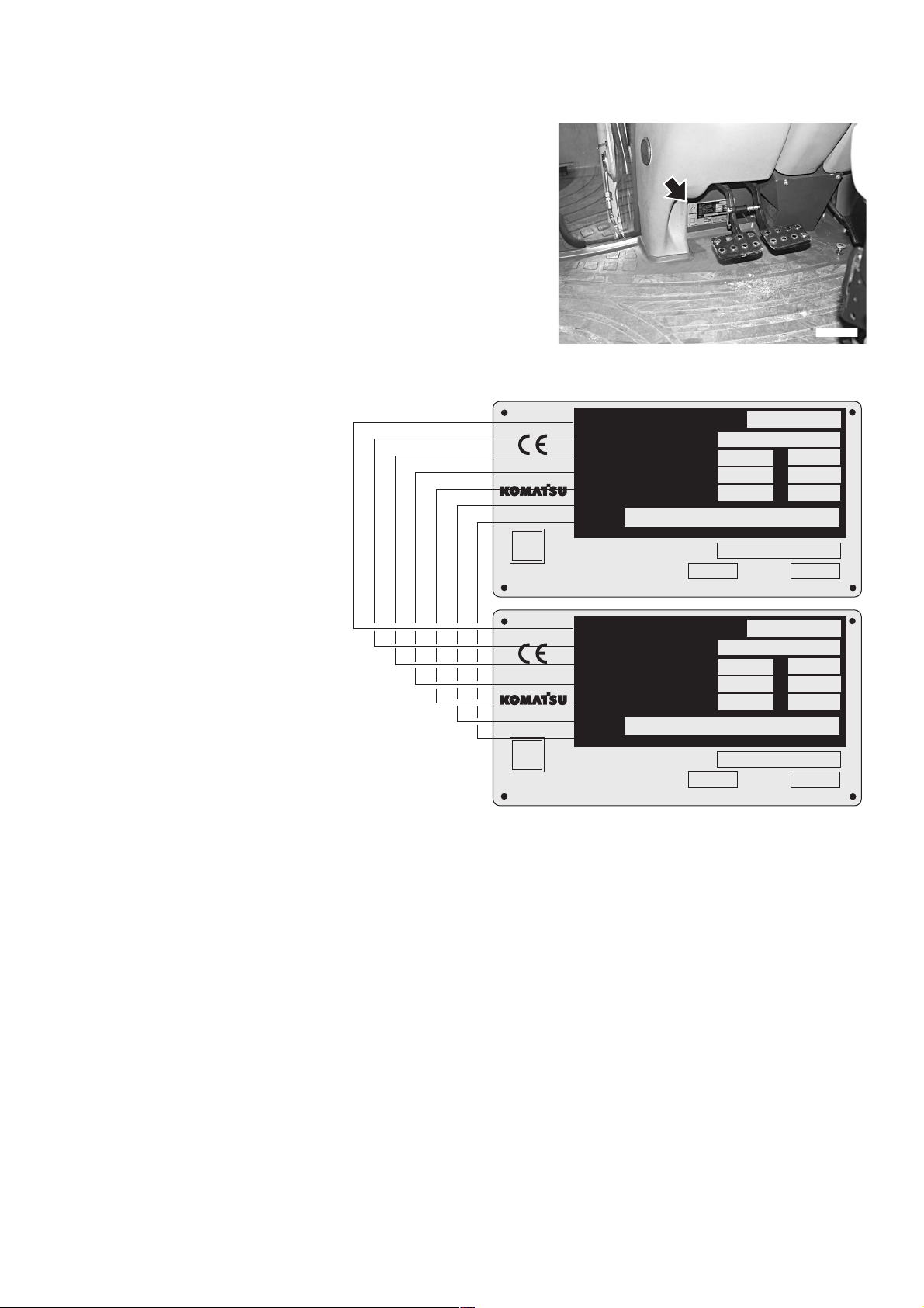
1.4.3 MACHINE IDENTIFICATION PLATE AND PRODUCT IDENTIFICATION NUMBER (PIN)
The Komatsu BACKHOE LOADERS described in this manual
are CE marked, in fact they are in full compliance with the EU
harmonised standards.
The Product Identification Number (PIN) is stamped on the
lower part of the plate. The customer must be able to indicate
the PIN at any time, that is why it must compulsorily be written
in the following table. The plate with the CE marking is applied
inside the cab, on the left vertical wall of the frame, at the
height of the brake pedals.
PRODUCT IDENTIFICATION
TIPO
TYPE - MODEL
NUMERO DI OMOLOGAZIONE
HOMOLOGATION NUMBER
MASSA TOTALE AMMISSIBILE
TOTAL MASS WEIGHT
CARICO AMMISSIBILE ASSE ANT.
WEIGHT FRONT AXLE
CARICO AMMISSIBILE ASSE POST.
WEIGHT REAR AXLE
Product Identification Number
PIN
- Massa rimorchiabile: non atto
MATRICOLA
SERIAL NUMBER
POTENZA MOTORE
MANUFACTURED BY KOMATSU UTILITY EUROPE S.p.A. 36025 NOVENTA VIC. (VI) -ITALY
TYPE
HOMOLOGATION NUMBER
TOTAL MASS WEIGHT
WEIGHT FRONT AXLE
WEIGHT REAR AXLE
Product Identification Number
PIN
- Towable weight: not suitable
SERIAL NUMBER
ENGINE POWER
MANUFACTURED BY KOMATSU UTILITY EUROPE S.p.A. 36025 NOVENTA VIC. (VI) -ITALY
FROM
FROM
FROM
FROM
FROM
FROM
DA
DA
DA
kg
kg
kg
ANNO
kW
kg
kg
kg
YEAR
kW
RKAB2680
A
TO
A
TO
A
TO
kg
kg
kg
37A-98-11840
RKA16060
TO
TO
TO
kg
kg
kg
37A-98-11840
7
Page 10
PRODUCT IDENTIFICATION
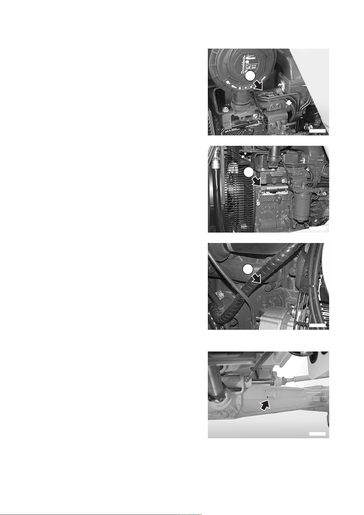
1.4.4 ENGINE SERIAL NUMBER AND EXHAUST GAS EMISSION PLATE
The identification plate (1) is fixed above the engine head and
indicates the engine model, total displacement and serial
number.
The identification plate (2) is fixed to the left side of the engine
block, bears the Manufacturer’s mark and contains the following data:
1 - Engine type
2 - Engine family
3 - Serial number
4 - EC Type Approval
5 - EPA
The serial number (3) is also stamped on the right side of the
cylinder block, on the upper part of the oil cooling heat exchanger.
1
RKAB2690
2
RKAB2700
1.4.5 FRONT AXLE SERIAL NUMBER
The serial number of the front axle is stamped on the plate positioned on the right side of the axle body.
3
RKAB2710
RKAB2720
8
Page 11
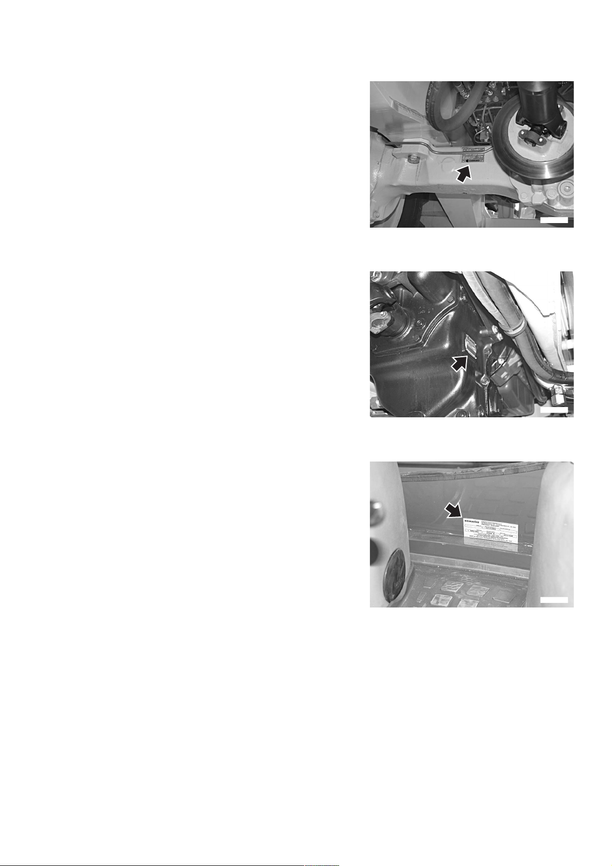
1.4.6 REAR AXLE SERIAL NUMBER
The serial number of the rear axle is stamped on the plate positioned on the right side of the axle body.
1.4.7 TRANSMISSION SERIAL NUMBER
The transmission serial number is stamped on the plate postioned on the right side of the transmission case.
PRODUCT IDENTIFICATION
RKAB2730
1.4.8 CAB SERIAL NUMBER
The cab serial number is stamped on the plate postioned on
the left side of the rear wall.
RKAB2750
RKAB2740
9
Page 12

PRODUCT IDENTIFICATION
1.4.9 SERIAL NUMBERS AND DEALER’S ADDRESS
Machine no. Mod.
Product identification number (PIN)
Engine no.
Front axle no.
Rear axle no.
Transmission no.
Cab no.
Dealer:
Address:
Contact person:
NOTES:
Tel.
10
Page 13

TABLE OF CONTENTS
TABLE OF CONTENTS
FOREWORD
1.1 FOREWORD.......................................................................................................................................... 1
1.2 INFORMATION ON SAFETY ................................................................................................................ 2
1.3 INTRODUCTION ................................................................................................................................... 4
1.3.1 INTENDED USES .................................................................................................................... 4
1.3.2 IMPROPER OR UNAUTHORIZED USE .................................................................................. 4
1.3.3 MAIN CHARACTERISTICS...................................................................................................... 5
1.3.4 RUNNING-IN ............................................................................................................................ 5
1.4 PRODUCT IDENTIFICATION ............................................................................................................... 6
1.4.1 MACHINE IDENTIFICATION NUMBER (PIN) ......................................................................... 6
1.4.2 MACHINE IDENTIFICATION PLATE AND PRODUCT IDENTIFICATION NUMBER
(PIN) (alternatively for some markets) ..................................................................................... 6
1.4.3 MACHINE IDENTIFICATION PLATE AND PRODUCT IDENTIFICATION NUMBER (PIN) .... 7
1.4.4 ENGINE SERIAL NUMBER AND EXHAUST GAS EMISSION PLATE ................................... 8
1.4.5 FRONT AXLE SERIAL NUMBER............................................................................................. 8
1.4.6 REAR AXLE SERIAL NUMBER ............................................................................................... 9
1.4.7 TRANSMISSION SERIAL NUMBER ........................................................................................ 9
1.4.8 CAB SERIAL NUMBER ............................................................................................................ 9
1.4.9 SERIAL NUMBERS AND DEALER’S ADDRESS .................................................................... 10
TABLE OF CONTENTS ........................................................................................................................ 11
SAFETY AND ACCIDENT PREVENTION
2.1 SAFETY, NOISE AND VIBRATION PLATES....................................................................................... 20
2.1.1 POSITION OF THE SAFETY PLATES .................................................................................... 20
2.1.2 PICTOGRAMS AND RELEVANT MEANINGS......................................................................... 22
2.1.3 POSITION OF THE NOISE PLATES ON MACHINES WITH CAB .......................................... 28
2.1.4 VIBRATIONS TO WHICH THE OPERATOR IS SUBJECTED ................................................ 29
2.2 GENERAL PRECAUTIONS .................................................................................................................. 30
2.2.1 GENERAL SAFETY RULES .................................................................................................... 30
2.2.2 SAFETY DEVICES AND GUARDS .......................................................................................... 30
2.2.3 CLOTHING AND PERSONAL PROTECTION ITEMS ............................................................. 30
2.2.4 UNAUTHORIZED MODIFICATIONS ....................................................................................... 30
2.2.5 LEAVING THE OPERATOR’S SEAT ....................................................................................... 31
2.2.6 GETTING ON AND OFF THE MACHINE................................................................................. 32
2.2.7 CHECKING THE REAR-VIEW MIRRORS .............................................................................. 32
2.2.8 PREVENTING FIRES DUE TO FUEL AND OIL ..................................................................... 33
2.2.9 PREVENTING BURNS ............................................................................................................ 33
2.2.10 PREVENTING DAMAGE DUE TO ASBESTOS POWDER .................................................... 34
2.2.11 PREVENTING DAMAGE CAUSED BY THE WORK EQUIPMENT ........................................ 34
2.2.12 FIRE EXTINGUISHERS AND FIRST AID KIT ........................................................................ 35
2.2.13 PRECAUTIONS CONCERNING THE CAB STRUCTURE ...................................................... 35
2.2.14 PRECAUTIONS CONCERNING THE EQUIPMENT ............................................................... 35
2.3 PRECAUTIONS TO BE TAKEN BEFORE STARTING THE ENGINE................................................. 36
2.3.1 SAFETY ON THE WORK SITE ............................................................................................... 36
2.3.2 FIRE PREVENTION ................................................................................................................ 36
2.3.3 PRECAUTIONS TO BE TAKEN FOR THE OPERATOR'S CAB ............................................. 36
2.3.4 ROOM VENTILATION ............................................................................................................. 37
2.3.5 CLEANING WINDOWS, MIRRORS AND LIGHTS - CHECKING THE WINDSHIELD
WIPER BLADES AND THE BULBS ......................................................................................... 37
11
Page 14

TABLE OF CONTENTS
2.4 PRECAUTIONS TO BE TAKEN DURING WORK ................................................................................ 38
2.4.1 WHEN STARTING THE ENGINE............................................................................................. 38
2.4.2 RULES FOR TRAVELLING ON ROADS.................................................................................. 38
2.4.3 HAND SIGNALS ....................................................................................................................... 39
2.4.4 CHECKS FOR TRAVELLING IN REVERSE ............................................................................ 44
2.4.5 MOVING THE MACHINE .........................................................................................................44
2.4.6 WORKING ON SLOPES .........................................................................................................45
2.4.7 PREVENTING ELECTROCUTION .......................................................................................... 46
2.4.8 VISIBILITY ................................................................................................................................ 47
2.4.9 WORKING ON ICY OR SNOW-COVERED SURFACES......................................................... 47
2.4.10 PREVENTING DAMAGE CAUSED BY THE WORK EQUIPMENT ......................................... 47
2.4.11 WORKING ON LOOSE GROUND ........................................................................................... 47
2.4.12 PARKING THE MACHINE........................................................................................................ 48
2.5 TRANSPORTING THE MACHINE ON OTHER VEHICLES ................................................................. 49
2.5.1 LOADING AND UNLOADING THE MACHINE ........................................................................ 49
2.5.2 TRANSPORT............................................................................................................................ 49
2.6 BATTERY .............................................................................................................................................. 50
2.6.1 PREVENTING RISKS THAT MAY BE DUE TO THE BATTERY ............................................. 50
2.6.2 STARTING WITH BOOSTER CABLES ................................................................................... 50
2.7 PRECAUTIONS FOR EMERGENCY RECOVERY ............................................................................... 51
2.8 PRECAUTIONS TO BE TAKEN DURING MAINTENANCE ................................................................. 52
2.8.1 WARNING PLATES.................................................................................................................. 52
2.8.2 TOOLS ..................................................................................................................................... 52
2.8.3 PERSONNEL............................................................................................................................ 53
2.8.4 EQUIPMENT ........................................................................................................................... 53
2.8.5 WORKING UNDER THE MACHINE ........................................................................................ 53
2.8.6 KEEPING THE MACHINE CLEAN .......................................................................................... 54
2.8.7 USE OF THE ENGINE DURING MAINTENANCE ................................................................... 54
2.8.8 PERIODICAL CHANGE OF THE SAFETY RELATED PARTS................................................ 54
2.8.9 STOP THE ENGINE BEFORE CARRYING OUT ANY MAINTENANCE OPERATION
OR INSPECTION .................................................................................................................... 55
2.8.10 RULES TO BE FOLLOWED DURING FUEL OR OIL TOPPING UP ...................................... 56
2.8.11 CHECKING THE COOLANT LEVEL IN THE RADIATOR........................................................ 56
2.8.12 USING LAMPS ......................................................................................................................... 56
2.8.13 PRECAUTIONS CONCERNING THE BATTERY AND THE ALTERNATOR .......................... 57
2.8.14 PRECAUTIONS CONCERNING THE STARTER .................................................................... 57
2.8.15 HANDLING HIGH-PRESSURE PIPES..................................................................................... 58
2.8.16 PRECAUTIONS TO BE TAKEN WHEN WORKING ON HIGH- PRESSURE SYSTEMS ....... 58
2.8.17 PRECAUTIONS FOR MAINTENANCE WORK INVOLVING HIGH TEMPERATURES
AND PRESSURES ...................................................................................................................58
2.8.18 HYDRAULIC ACCUMULATOR ................................................................................................ 59
2.8.19 COOLING FAN AND FAN BELT .............................................................................................. 59
2.8.20 WASTE MATERIALS................................................................................................................ 59
2.8.21 PRECAUTIONS CONCERNING TECHNOPOLYMERS AND ELASTOMERS........................ 60
2.8.22 PRECAUTIONS TO BE TAKEN WHEN INFLATING THE TYRES ......................................... 60
2.8.23 PRECAUTIONS FOR THE INSTALLATION OF THE EXHAUST SYSTEM TAILPIPE............ 61
2.8.24 PRECAUTIONS TO BE TAKEN WHEN USING SYNTHETIC BIODEGRADABLE
OIL TYPE «HEES»................................................................................................................... 61
12
Page 15

TABLE OF CONTENTS
DESCRIPTION AND USE OF THE MACHINE
3.1 SAFETY LOCKS ................................................................................................................................... 64
3.1.1 FRONT LOADER LOCKS ........................................................................................................ 64
3.1.2 BACKHOE LOCKS ................................................................................................................... 66
3.2 GENERAL VIEWS................................................................................................................................. 68
3.2.1 FRONT GENERAL VIEW .........................................................................................................68
3.2.2 BACKHOE GENERAL VIEW.................................................................................................... 69
3.2.3 CAB INSIDE GENERAL VIEW ................................................................................................. 70
3.2.3.1 CAB INSIDE GENERAL VIEW (mechanical backhoe controls).............................. 70
3.2.3.2 CAB INSIDE GENERAL VIEW (backhoe servo controls) ....................................... 71
3.3 INSTRUMENTS AND CONTROLS ....................................................................................................... 72
3.3.1 FRONT INSTRUMENTS ..........................................................................................................72
3.3.2 SIDE INSTRUMENTS .............................................................................................................. 76
3.3.3 PUSH BUTTONS ON THE FRONT LOADER CONTROL LEVER .......................................... 84
3.3.4 PUSH BUTTON ON THE GEARSHIFT LEVER....................................................................... 85
3.3.5 CAB SWITCHES AND ELECTRIC ACCESSORIES ................................................................ 86
3.3.6 MACHINE CONTROLS ............................................................................................................ 89
3.3.6.1 MACHINE CONTROLS (version with mechanically-controlled backhoe) .............. 89
3.3.6.2 MACHINE CONTROLS (version with servo-assisted backhoe) ............................. 91
3.3.6.3 ADJUSTING THE CONTROLS .............................................................................. 111
3.4 FUSES AND RELAYS........................................................................................................................... 114
3.4.1 CENTRAL UNIT FUSES – RELAYS AND ENGINE LINE ........................................................ 114
3.4.1.1 FUSES ................................................................................................................... 114
3.4.1.2 RELAYS .................................................................................................................. 116
3.4.2 VENTILATION, HEATING AND AIR CONDITIONING FUSES AND RELAYS ........................ 117
3.4.2.1 FUSES ................................................................................................................... 117
3.4.2.2 RELAYS ................................................................................................................. 117
3.5 GUARDS, CAB AND DRIVER’S SEAT ................................................................................................ 118
3.5.1 ENGINE HOOD ........................................................................................................................ 118
3.5.2 CAB .......................................................................................................................................... 119
3.5.3 VENTILATION AND HEATING ................................................................................................ 122
3.5.4 AIR CONDITIONER (if installed) .............................................................................................. 123
3.5.5 SEAT ........................................................................................................................................ 125
3.5.5.1 SEAT (STANDARD) ............................................................................................... 125
3.5.5.2 SEAT (OPTIONAL) ................................................................................................ 126
3.5.6 SAFETY BELT.......................................................................................................................... 127
3.5.7 FIRE EXTINGUISHER ............................................................................................................ 127
3.5.8 FIRST AID KIT ......................................................................................................................... 127
3.5.9 TECHNICAL DOCUMENTATION ........................................................................................... 127
3.5.10 STORAGE COMPARTMENT .................................................................................................. 128
3.6 USE OF THE MACHINE........................................................................................................................ 129
3.6.1 CHECKS TO BE CARRIED OUT BEFORE STARTING THE ENGINE ................................... 129
3.6.1.1 VISUAL CHECKS.................................................................................................... 129
3.6.1.2 OPERATIONAL CHECKS ...................................................................................... 130
3.6.2 STARTING THE ENGINE ........................................................................................................ 131
3.6.2.1 STARTING WITH WARM ENGINE OR IN TEMPERATE CLIMATES ................... 131
3.6.2.2 STARTING WITH COLD ENGINE OR IN COLD CLIMATES ................................ 132
3.6.3 WARMING THE ENGINE ......................................................................................................... 133
3.6.4 HEATING THE HYDRAULIC OIL ............................................................................................. 133
3.6.5 HOW TO MOVE THE MACHINE ............................................................................................. 134
3.6.5.1 DIFFERENTIAL LOCKING...................................................................................... 135
3.6.5.2 ENGAGING THE FOUR-WHEEL DRIVE ............................................................... 135
13
Page 16

TABLE OF CONTENTS
3.6.5.3 WORKING ON SLOPES ........................................................................................ 136
3.6.5.4 MAXIMUM IMMERSION DEPTH ............................................................................ 137
3.7 PARKING THE MACHINE .................................................................................................................... 138
3.7.1 PARKING ON LEVEL GROUND .............................................................................................. 138
3.7.2 PARKING ON SLOPES............................................................................................................ 139
3.8 STOPPING THE ENGINE ..................................................................................................................... 140
3.9 TRANSPORTING THE MACHINE ON OTHER VEHICLES ................................................................. 141
3.9.1 LOADING AND UNLOADING THE MACHINE ......................................................................... 141
3.9.2 TRANSPORT............................................................................................................................ 142
3.10 PRECAUTIONS TO BE TAKEN IN THE COLD SEASON ................................................................... 143
3.10.1 FUEL AND LUBRICANTS ........................................................................................................ 143
3.10.2 COOLANT ................................................................................................................................ 143
3.10.3 BATTERY ................................................................................................................................. 144
3.10.4 OTHER PRECAUTIONS .......................................................................................................... 144
3.10.5 PRECAUTIONS TO BE TAKEN AT THE END OF WORK ...................................................... 144
3.11 PRECAUTIONS TO BE TAKEN AT THE END OF THE WINTER........................................................ 145
3.12 USING THE MACHINE AS A LOADER ................................................................................................ 146
3.12.1 BUCKET POSITION INDICATOR ............................................................................................ 146
3.12.2 ORGANIZING THE WORK AREA ............................................................................................ 146
3.12.2.1 LOADING HEAPED AND LEVEL MATERIAL ........................................................ 147
3.12.2.2 LOADING OPERATIONS ON SLOPES.................................................................. 148
3.12.3 CHANGING THE STANDARD FRONT BUCKET ................................................................... 148
3.13 USING THE MACHINE AS AN EXCAVATOR ...................................................................................... 149
3.13.1 POSITIONING THE BUCKET ACCORDING TO THE WORK THAT MUST
BE CARRIED OUT .................................................................................................................. 149
3.13.2 POSITIONING THE MACHINE FOR DIGGING OPERATIONS............................................... 150
3.13.3 SLIDING THE BACKHOE UNIT SIDEWARDS ........................................................................ 151
3.13.4 DIGGING METHOD.................................................................................................................. 152
3.13.4.1 CHANGING THE BACKHOE BUCKET................................................................... 153
3.14 LONG PERIODS OF INACTIVITY ........................................................................................................ 154
3.14.1 PREPARING THE MACHINE FOR A LONG PERIOD OF INACTIVITY .................................. 154
3.14.2 PREPARING THE ENGINE FOR A LONG PERIOD OF INACTIVITY..................................... 156
3.14.3 MAINTENANCE DURING A PERIOD OF INACTIVITY ........................................................... 156
3.14.4 RESTARTING THE ENGINE.................................................................................................... 157
3.14.5 AFTER THE PERIOD OF INACTIVITY .................................................................................... 157
3.15 TROUBLESHOOTING .......................................................................................................................... 158
3.15.1 HOW TO REMOVE THE MACHINE......................................................................................... 158
3.15.2 AFTER THE FUEL HAS RUN OUT .......................................................................................... 158
3.15.3 IF THE BATTERY HAS RUN DOWN ....................................................................................... 159
3.15.3.1 STARTING WITH BOOSTER CABLES .................................................................. 160
3.15.4 OTHER TROUBLES................................................................................................................. 161
3.15.4.1 ELECTRICAL CIRCUIT........................................................................................... 161
3.15.4.2 HYDRAULIC SYSTEM ............................................................................................ 161
3.15.4.3 BRAKING SYSTEM ................................................................................................ 162
3.15.4.4 CONVERTER .......................................................................................................... 162
3.15.4.5 ENGINE................................................................................................................... 162
14
Page 17

TABLE OF CONTENTS
MAINTENANCE
4.1 GUIDE TO MAINTENANCE .................................................................................................................. 166
4.2 MAINTENANCE NOTES ....................................................................................................................... 168
4.2.1 NOTES REGARDING THE ENGINE ....................................................................................... 168
4.2.1.1 ENGINE OIL............................................................................................................ 168
4.2.1.2 COOLANT ............................................................................................................... 168
4.2.1.3 FUEL ....................................................................................................................... 169
4.2.2 NOTES REGARDING THE HYDRAULIC SYSTEM................................................................. 169
4.2.3 NOTES REGARDING THE ELECTRIC SYSTEM.................................................................... 170
4.2.4 NOTES REGARDING LUBRICATION ..................................................................................... 170
4.2.5 PARTS SUBJECT TO WEAR THAT PERIODICALLY NEED CHANGING.............................. 171
4.3 FUEL, COOLANT AND LUBRICANTS ................................................................................................ 172
4.3.1 LUBRICATION WITH GREASE ............................................................................................... 173
4.3.2 HOMOLOGATED SYNTHETIC BIODEGRADABLE LUBRICANTS “HEES” ........................... 174
4.4 DRIVING TORQUES ............................................................................................................................. 175
4.4.1 STANDARD DRIVING TORQUES FOR SCREWS AND NUTS .............................................. 175
4.4.2 SPECIFIC DRIVING TORQUES FOR SCREWS AND NUTS ................................................. 176
4.4.3 STANDARD DRIVING TORQUES FOR HOSES WITH ORFS................................................ 176
4.5 LUBRICATION ...................................................................................................................................... 177
4.5.1 LUBRICATION DIAGRAM........................................................................................................ 177
4.5.2 LUBRICATION DIAGRAM (4in1 bucket and pallet forks) ........................................................ 178
4.5.3 LUBRICATION DIAGRAM (front bucket quick couplings) ........................................................ 179
4.5.4 LUBRICATION DIAGRAM (offset device) ................................................................................ 180
4.6 PERIODICAL CHANGE OF THE SAFETY RELATED COMPONENTS.............................................. 181
4.6.1 SAFETY RELATED PARTS ..................................................................................................... 182
4.6.1.1 FUEL SYSTEM ...................................................................................................... 182
4.6.1.2 DELIVERY HYDRAULIC SYSTEM ........................................................................ 183
4.6.1.3 FRONT LOADER HYDRAULIC SYSTEM............................................................... 184
4.6.1.4 BACKHOE HYDRALIC SYSTEM............................................................................ 185
4.6.1.5 OPERATOR’S SAFETY ......................................................................................... 186
4.7 MAINTENANCE PLAN.......................................................................................................................... 187
4.8 MAINTENANCE PROCEDURES .......................................................................................................... 189
4.8.1 WHEN REQUIRED................................................................................................................... 189
4.8.1.a CHECKING, CLEANING OR CHANGING THE ENGINE AIR FILTERS ................ 189
4.8.1.b CHECKING AND CLEANING THE CAB AIR FILTER ............................................ 190
4.8.1.c CHECKING AND CLEANING THE AIR RECIRCULATION FILTER
(only for machines with air conditioner)................................................................... 191
4.8.1.d CHECKING THE DETERGENT LEVEL IN THE WINDSHIELD WASHER
RESERVOIR ........................................................................................................... 191
4.8.1.e CHECKING THE WINDSHIELD WIPER BLADES.................................................. 192
4.8.1.f LUBRICATING THE CAB DOOR HINGES ............................................................. 192
4.8.1.g FUSES AND RELAYS – CHECK AND CHANGE ................................................... 192
4.8.1.h BLEEDING THE BRAKING CIRCUIT ..................................................................... 193
4.8.1.i CHECKING AND ADJUSTING THE FRONT WHEEL TOE-IN .............................. 194
4.8.1.j CHECKING THE BRAKING EFFICIENCY.............................................................. 194
4.8.1.k CHECKING AND ADJUSTING THE PARKING BRAKE......................................... 195
4.8.1.l CHECKING AND ADJUSTING THE BRAKE PEDAL STROKE ............................. 196
4.8.1.m ADJUSTING THE AUTOMATIC RETURN-TO-DIG DEVICE OF THE
FRONT BUCKET (if installed) ................................................................................. 196
4.8.1.n CHECKING AND ADJUSTING THE STABILIZER SLACK .................................... 197
4.8.2 MAINTENANCE INTERVALS IN CASE OF USE OF THE DEMOLITION HAMMER .............. 198
4.8.2.a CHANGING THE HYDRAULIC OIL FILTER ........................................................... 198
15
Page 18

TABLE OF CONTENTS
4.8.2.b CHANGING THE HYDRAULIC OIL ........................................................................ 198
4.8.3 CHECKS TO BE CARRIED OUT BEFORE STARTING THE ENGINE ................................... 199
4.8.3.a VARIOUS CHECKS ................................................................................................ 199
4.8.3.b CHECKING THE COOLANT LEVEL....................................................................... 199
4.8.3.c CHECKING THE FUEL LEVEL............................................................................... 200
4.8.3.d CHECKING THE ENGINE OIL LEVEL ................................................................... 200
4.8.4 MAINTENANCE EVERY 10 HOURS OF OPERATION ........................................................... 201
4.8.4.a LUBRICATING THE JOINTS .................................................................................. 201
4.8.5 MAINTENANCE AFTER THE FIRST 50 HOURS OF OPERATION
(Only for machines in which synthetic biodegradable oil type HEES is used) .......................... 203
4.8.6 MAINTENANCE EVERY 50 HOURS OF OPERATION ........................................................... 203
4.8.6.a CHECKING THE HYDRAULIC OIL LEVEL ............................................................ 203
4.8.6.b CHECKING THE FLUID LEVEL IN THE RADIATOR ............................................. 204
4.8.6.c CHECKING THE BRAKING SYSTEM OIL LEVEL ................................................. 204
4.8.6.d LUBRICATING THE PROPELLER SHAFTS .......................................................... 205
4.8.6.e LUBRICATING THE FRONT AXLE JOINTS AND CENTRAL COUPLING ............ 206
4.8.6.f CHECKING THE TYRE PRESSURE ..................................................................... 206
4.8.6.g DRAINING THE WATER SEPARATOR ................................................................. 207
4.8.7 MAINTENANCE AFTER THE FIRST 250 HOURS OF OPERATION ...................................... 208
4.8.8 MAINTENANCE EVERY 250 HOURS OF OPERATION ......................................................... 208
4.8.8.a CHECKING THE ALTERNATOR-FAN BELT.......................................................... 208
4.8.8.b CHECKING AND ADJUSTING THE A/C COMPRESSOR BELT TENSION
(only for machines with air conditioner) ................................................................... 209
4.8.8.c CHECKING THE BATTERY ELECTROLYTE LEVEL ............................................ 210
4.8.8.d CHECKING THE FRONT AXLE OIL LEVELS ........................................................ 211
4.8.8.e CHECKING THE REAR AXLE OIL LEVEL ............................................................. 211
4.8.8.f CHECKING THE HYDRAULIC TRANSMISSION OIL LEVEL ............................... 212
4.8.8.g CHECKING THE WHEEL NUT DRIVING TORQUE............................................... 212
4.8.9 MAINTENANCE AFTER THE FIRST 500 HOURS OF OPERATION
(Only for machines in which synthetic biodegradable oil type HEES is used) .......................... 213
4.8.10 MAINTENANCE EVERY 500 HOURS OF OPERATION ......................................................... 213
4.8.10.a CHANGING THE ENGINE OIL ............................................................................... 213
4.8.10.b CHANGING THE ENGINE OIL FILTER.................................................................. 214
4.8.10.c CHANGING THE HYDRAULIC SYSTEM OIL FILTER ........................................... 214
4.8.10.d CHANGING THE FUEL FILTER ............................................................................. 217
4.8.10.e DRAINING THE FUEL TANK .................................................................................. 218
4.8.10.f DRAINING THE HYDRAULIC OIL TANK
(only for machines in which synthetic biodegradable oil type HEES is used) ......... 219
4.8.10.g CLEANING THE OUTSIDE OF THE RADIATOR .................................................. 220
4.8.10.h CLEANING THE OUTSIDE OF THE A/C CONDENSER
(only for machines with air conditioner) .................................................................. 221
4.8.11 MAINTENANCE EVERY 1000 HOURS OF OPERATION ....................................................... 222
4.8.11.a CHANGING THE FRONT AXLE OIL ...................................................................... 222
4.8.11.b CHANGING THE REAR AXLE OIL......................................................................... 223
4.8.11.c CHANGING THE HYDRAULIC TRANSMISSION OIL............................................ 224
4.8.11.d CHANGING THE HYDRAULIC TRANSMISSION OIL FILTER .............................. 225
4.8.12 MAINTENANCE EVERY 2000 HOURS OF OPERATION ....................................................... 226
4.8.12.a CHANGING THE HYDRAULIC OIL AND CLEANING THE INTAKE FILTER......... 226
4.8.12.b CHANGING THE COOLANT ................................................................................. 228
4.8.12.c CHANGING THE BRAKING SYSTEM OIL ............................................................. 229
4.8.12.d CHECKING THE ALTERNATOR AND THE STARTER ......................................... 230
4.8.12.e CHANGING THE ALTERNATOR BELT.................................................................. 230
4.8.12.f CHECKING THE A/C COOLING GAS QUANTITY
(only for machines with air conditioner) ................................................................... 230
4.8.13 MAINTENANCE EVERY 3000 HOURS OF OPERATION ....................................................... 231
16
Page 19

TABLE OF CONTENTS
4.8.13.a CHECKING THE ENGINE RETAINING SCREWS AND DAMPING ELEMENTS .. 231
4.8.13.b CHECKING AND ADJUSTING THE ENGINE VALVE CLEARANCE AND
THE INJECTION TIMING ADVANCE ..................................................................... 231
4.8.14 MAINTENANCE EVERY 4000 HOURS OF OPERATION ....................................................... 232
4.8.14.a CHANGING THE A/C DEWATERING FILTER
(Only for machines with air conditioner) ................................................................. 232
4.8.14.b CHECKING THE OPERATING CONDITIONS OF THE A/C COMPRESSOR
(Only for machines with air conditioner) ................................................................. 232
4.8.14.c CHANGING THE ENGINE THERMOSTATIC VALVE ............................................ 232
TECHNICAL SPECIFICATIONS
5.1 TECHNICAL DATA ............................................................................................................................... 234
5.1.1 STANDARD OVERALL DIMENSIONS .................................................................................... 234
5.1.1.1 OVERALL DIMENSIONS WITH STANDARD ARM ................................................ 234
5.1.1.2 OVERALL DIMENSIONS WITH TELESCOPIC ARM ............................................. 234
5.1.2 TECHNICAL CHARACTERISTICS .......................................................................................... 235
5.1.3 LIFTING CAPACITIES ............................................................................................................. 237
5.1.3.1 SYMBOL TABLE ..................................................................................................... 237
5.1.3.2 LIFTING CAPACITIES (STANDARD ARM) ............................................................ 238
5.1.3.3 LIFTING CAPACITIES (TELESCOPIC ARM) ......................................................... 239
AUTHORIZED OPTIONAL EQUIPMENT
6.1 AUTHORIZED OPTIONAL EQUIPMENT ............................................................................................. 242
6.1.1 PRECAUTIONS REGARDING SAFETY .................................................................................. 242
6.1.2 PRECAUTIONS REGARDING THE INSTALLATION OF EQUIPMENT.................................. 243
6.1.3 CHARACTERISTICS OF THE OPTIONAL EQUIPMENT........................................................ 244
6.2 FRONT EQUIPMENT QUICK COUPLING DEVICES .......................................................................... 245
6.2.1 MANUAL QUICK COUPLING .................................................................................................. 245
6.2.2 HYDRAULIC QUICK COUPLING FOR STANDARD BUCKET ............................................... 246
6.2.3 HYDRAULIC QUICK COUPLING FOR 4in1 BUCKET AND OPTIONAL EQUIPMENT
WITH UNIDIRECTIONAL OIL FLOW ...................................................................................... 246
6.3 4in1 BUCKET........................................................................................................................................ 247
6.3.1 DESCRIPTION AND CONTROLS .......................................................................................... 247
6.3.2 SAFETY DEVICES .................................................................................................................. 247
6.3.3 INSTALLING THE 4in1 BUCKET ............................................................................................ 248
6.3.4 USING THE 4in1 BUCKET ...................................................................................................... 249
6.3.5 MAINTENANCE ....................................................................................................................... 249
6.4 PALLET FORKS ................................................................................................................................... 250
6.4.1 DESCRIPTION ......................................................................................................................... 250
6.4.2 SAFETY DEVICES .................................................................................................................. 251
6.4.3 USING THE FORKS ................................................................................................................ 251
6.4.3.1 PREPARING THE PALLET FORKS FOR USE ..................................................... 252
6.4.3.2 OVERTURNING THE FORKS FOR TRAVEL ON ROADS ................................... 252
6.4.4 REMOVING THE FORKS ........................................................................................................ 253
6.4.5 INSTALLING THE FORKS ....................................................................................................... 253
6.4.6 MAINTENANCE ....................................................................................................................... 253
6.5 BACKHOE TELESCOPIC ARM............................................................................................................ 254
6.5.1 DESCRIPTION AND CONTROL .............................................................................................. 254
6.5.1.1 CONTROL (version with mechanically-controlled backhoe) .................................. 254
6.5.1.2 CONTROL (version with servo-assisted backhoe).................................................. 254
6.5.2 SAFETY DEVICES ................................................................................................................... 255
6.5.3 USING THE TELESCOPIC ARM ............................................................................................. 255
6.5.4 MAINTENANCE ....................................................................................................................... 256
6.5.4.1 ADJUSTING THE GUIDE SLACK........................................................................... 256
17
Page 20

TABLE OF CONTENTS
6.6 CONFIGURATION FOR THE INSTALLATION OF THE DEMOLITION HAMMER ............................. 258
6.6.1 DESCRIPTION AND CONTROL .............................................................................................. 258
6.6.1.1 CONTROL (version with mechanically-controlled backhoe) ................................... 258
6.6.1.2 CONTROL (version with servo-assisted backhoe).................................................. 258
6.6.2 USE OF THE DEMOLITION HAMMER AND RULES TO BE OBSERVED ............................. 259
6.6.3 INSTALLING AND REMOVING THE DEMOLITION HAMMER ............................................... 263
6.6.3.1 INSTALLING THE HAMMER .................................................................................. 263
6.6.3.2 REMOVING THE HAMMER.................................................................................... 265
6.6.4 USING THE HAMMER ............................................................................................................. 265
6.6.5 MAINTENANCE........................................................................................................................ 265
6.7 APPLICATION OF THE OFFSET DEVICE ........................................................................................... 266
6.7.1 DESCRIPTION AND CONTROL ............................................................................................. 266
6.7.1.1 CONTROL (version with mechanically-controlled backhoe) ................................... 266
6.7.1.2 CONTROL (version with servo-assisted backhoe).................................................. 267
6.7.2 MAINTENANCE........................................................................................................................ 267
6.8 CONFIGURATION FOR THE USE OF OPTIONAL EQUIPMENT WITH
UNIDIRECTIONAL OIL FLOW.............................................................................................................. 268
6.8.1 DESCRIPTION AND CONTROL ............................................................................................. 268
6.8.1.1 CONTROL (version with mechanically-controlled backhoe) ................................... 268
6.8.1.2 CONTROL (version with servo-assisted backhoe).................................................. 268
6.8.2 INSTALLING AND CONNECTING THE EQUIPMENT ........................................................... 269
6.8.3 MAINTENANCE........................................................................................................................ 269
6.9 CONFIGURATION FOR THE USE OF THE CLAMSHELL BUCKET .................................................. 270
6.9.1 DESCRIPTION AND CONTROL .............................................................................................. 270
6.9.1.1 CONTROL (version with mechanically-controlled backhoe) ................................... 270
6.9.1.2 CONTROL (version with servo-assisted backhoe).................................................. 271
6.9.2 INSTALLING THE CLAMSHELL BUCKET............................................................................... 272
6.9.3 USING THE CLAMSHELL BUCKET ........................................................................................ 273
6.9.4 MAINTENANCE........................................................................................................................ 273
6.10 CONFIGURATION FOR THE USE OF THE HAND HYDRAULIC HAMMER....................................... 274
6.10.1 DESCRIPTION AND CONTROL .............................................................................................. 274
6.10.2 INSTALLING AND REMOVING THE HAND HAMMER .......................................................... 275
6.10.2.1 CONNECTING THE HAND HAMMER.................................................................... 275
6.10.2.2 REMOVING THE CONNECTIONS ........................................................................ 276
6.10.3 USING THE HAMMER ............................................................................................................. 276
6.10.4 MAINTENANCE........................................................................................................................ 276
6.11 LOAD STABILIZER SYSTEM (LSS) (Optional) .................................................................................. 277
6.11.1 LOAD STABILIZER SYSTEM (LSS) ACCUMULATOR ........................................................... 277
6.12 REAR EQUIPMENT MECHANICAL QUICK COUPLING DEVICE ...................................................... 278
6.12.1 EQUIPMENT COUPLING AND RELEASE PROCEDURE ...................................................... 279
6.12.2 MAINTENANCE........................................................................................................................ 280
18
Page 21

SAFETY AND
ACCIDENT PREVENTION
19
Page 22
SAFETY, NOISE AND VIBRATION PLATES
42N-93-1
1380
42
N
9
3-1
1220
42N-93-1
1360
42N-
93-1
13
8
0
3
95
-
9
3
-
1
1
330
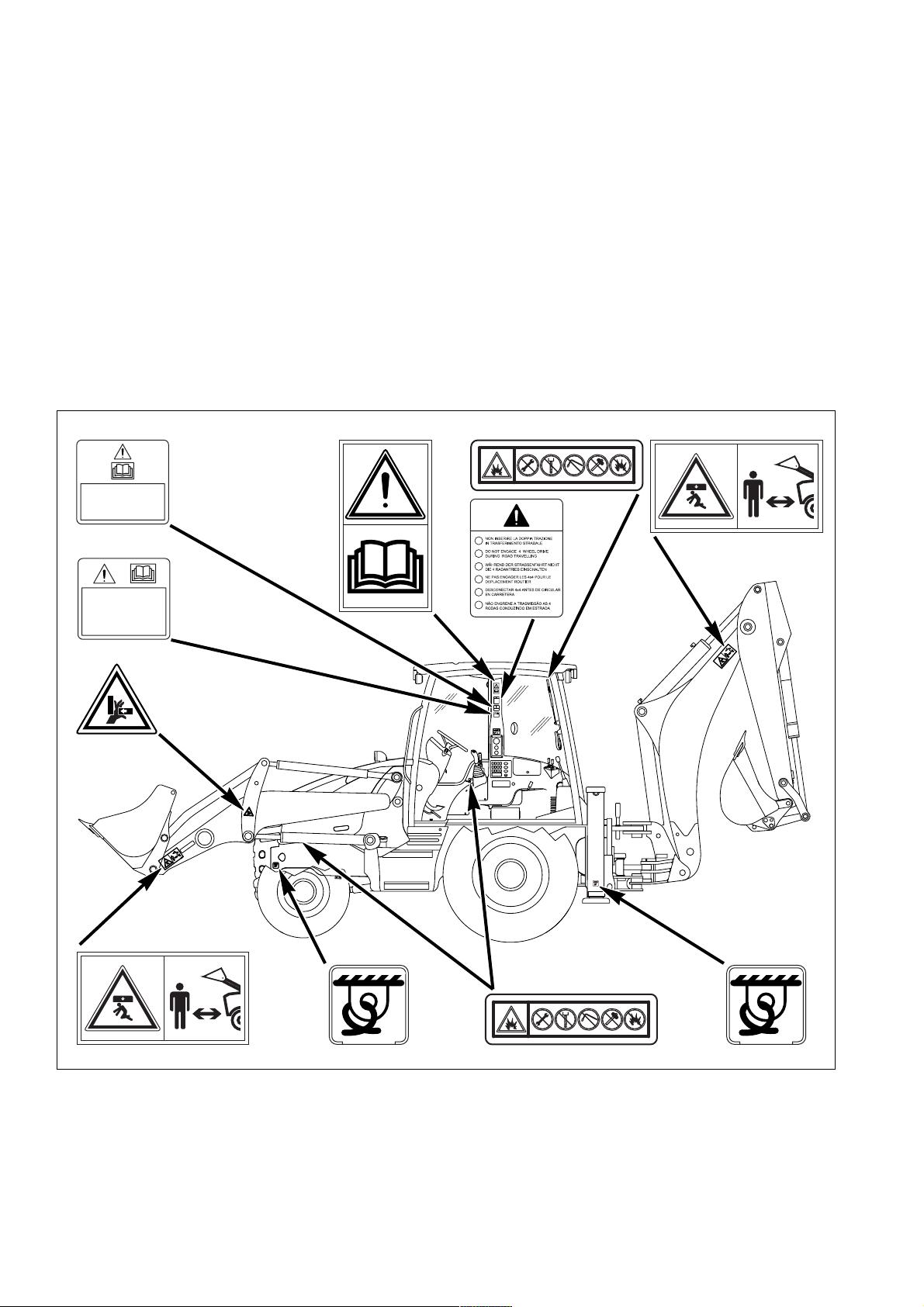
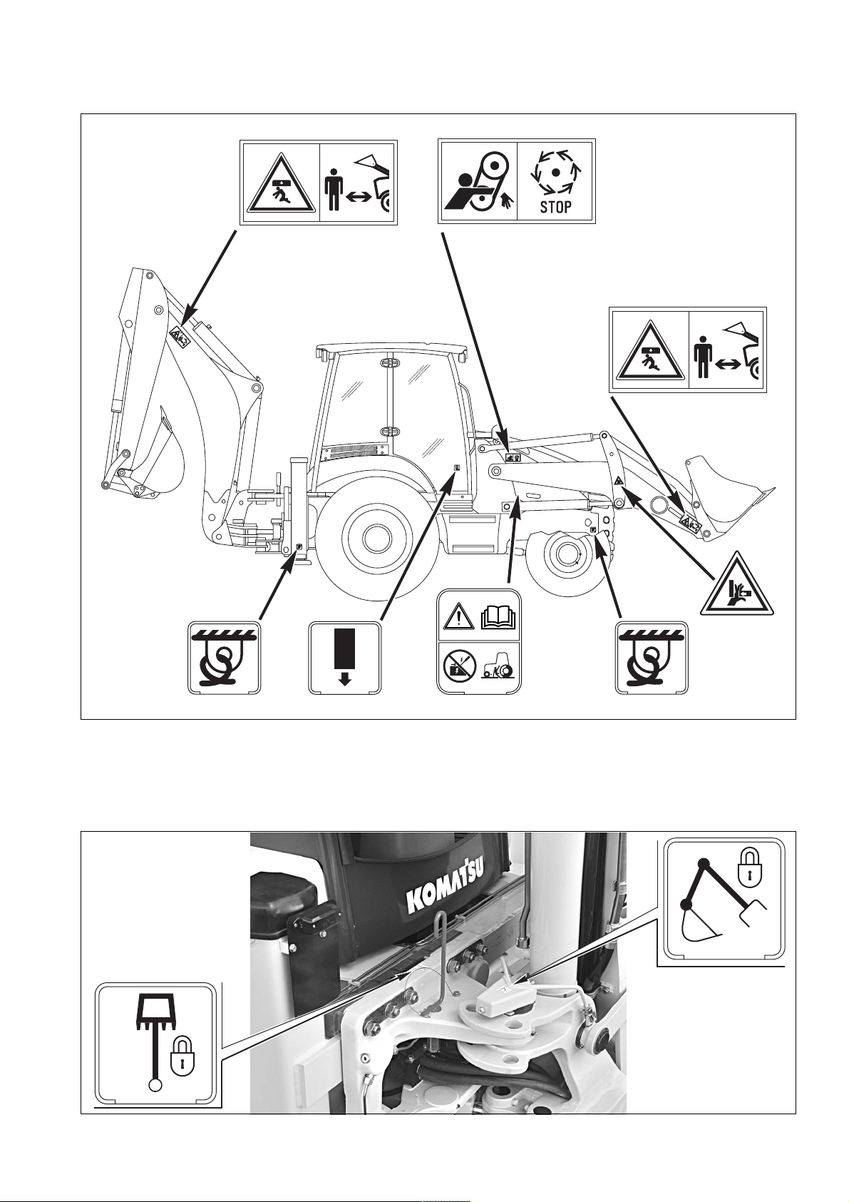
2.1 SAFETY, NOISE AND VIBRATION PLATES
2.1.1 POSITION OF THE SAFETY PLATES
q The safety plates must always be legible and in good conditions; for this reason, if they are dirty with dust, oil or
grease, it is necessary to clean them with a solution made of water and detergent. Do not use fuel, petrol or solvents.
q If the plates are damaged, ask for new ones to Komatsu or to your Komatsu Dealer.
q In case of replacement of a component provided with a safety plate, make sure that this plate is applied also on
the new piece.
q The machine can be provided with other plates in addition to those indicated below; in any case, keep also to the
instructions given in the additional plates.
DURANTE I TRASFERIMENTI
SU STRADA I PEDALI FRENO
DEVONO ESSERE COLLEGATI
CON APPOSITO SPINOTTO
PRIMA DI PARTIRE PER IL
TRASFERIMENTO SU
STRADA BLOCCARE LA LEVA
COMANDO PALA!
I
GB
D
F
E
P
0
8
3
1
1
3
9
N
2
4
3
9
5
-
9
3
-
1
1
3
3
42N-93-11130
NON INSERIRE LA DOPPIA TRAZIONE
I
IN TRASFERIMENTO STRADALE
DO NOT ENGAGE 4 WHEEL DRIVE
GB
DURING ROAD TRAVELLING
W˜HREND DER STRASSENFAHRT NICHT
D
DIE 4 RADANTRIEB EINSCHALTEN
NE PAS ENGAGER LES 4x4 POUR LE
F
DEPLACEMENT ROUTIER
DESCONECTAR 4x4 ANTES DE CIRCULAR
E
EN CARRETERA
NˆO ENGRENE A TRASMISSˆO AS 4
P
RODAS CONDUZINDO EM ESTRADA
42N-93-11120
DURANTE I TRASFERIMENTI
SU STRADA I PEDALI FRENO
DEVONO ESSERE COLLEGATI
CON APPOSITO SPINOTTO
42N-93-11110
PRIMA DI PARTIRE PER IL
TRASFERIMENTO SU
STRADA BLOCCARE LA LEVA
COMANDO PALA!
+
L
+
SPEED CONTROL
BUCKET CLOSE
L
KICK-DOWN
BUCKET OPEN
DIFFERENTIAL
DECLUTCH
LOCK
4
2
N
9
3
-1
1
2
2
0
g
k
0
0
0
1
L
W
S
0
8
3
1
1
-
3
9
-
N
2
4
42N-93-1
1360
0
20
RKA13480
Page 23
SAFETY, NOISE AND VIBRATION PLATES
SW
L
10
00 kg
RKA13490
42N-93-11310
42N-93-11320
RKAB4740
21
Page 24
SAFETY, NOISE AND VIBRATION PLATES
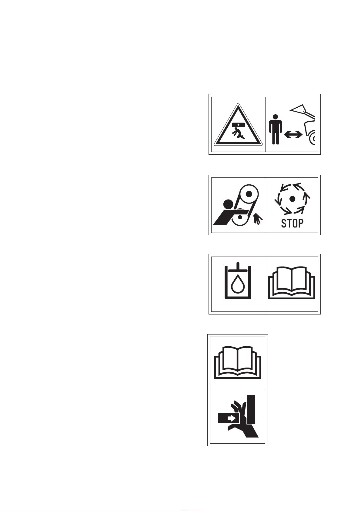
2.1.2 PICTOGRAMS AND RELEVANT MEANINGS
The warning and danger signs applied onto the machine are accompanied by or illustrated through pictograms.
The personnel in charge with handling and maintenance operations must know the symbols contained in the pictograms perfectly; the symbols and the relevant meanings are explained in the following list.
WORK AREA
q Do not approach or stand in the equipment operating radius
when the boom and the bucket are lifted.
42N-93-11380
RKA14690
DO NOT OPEN THE ENGINE HOOD
q Do not open or remove the hood when the engine is running.
HYDRAULIC OIL TOPPING UP
q (Only for machines in which synthetic biodegradable oil type
HEES is used)
OVERTURNING THE FORKS
q When overturning the forks for use or storage, be very care-
ful, since hands and feet may be seriously injured or even
cut off.
42N-93-11370
RKA14700
BIO-OIL
42N-93-11370
RKA14710
22
RKA14720
Page 25
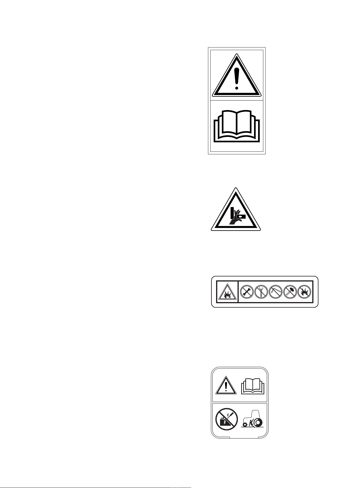
CONSULT THE MANUAL
q Carefully read the contents of the manual before using the
machine or performing maintenance operations.
RISK OF CRUSHING
q Do not touch or stand near moving parts, since your hands
may be crushed or cut off.
SAFETY, NOISE AND VIBRATION PLATES
42N-93-11130
RKA14730
PRECAUTIONS TO BE TAKEN WHEN HANDLING THE GAS SHOCK ABSORBERS
q Do not remove the shock absorber.
q Do not bring the shock absorber near sparks or naked
flames.
q Do not make holes in the shock absorber, do not weld or use
oxyhydrogen flames.
q Do not hit the shock absorber.
DO NOT START THE ENGINE WITH INCORRECT
PROCEDURES
q Start the engine and operate the machine only while seated
with fastened safety belt.
q Do not attempt to start the engine by causing a short-circuit
with the terminals of the starter.
This may cause serious injury and even death.
42N-93-11220
RKA14740
395-93-11330
RKA14750
42N-93-11350
RKA14760
23
Page 26
SAFETY, NOISE AND VIBRATION PLATES
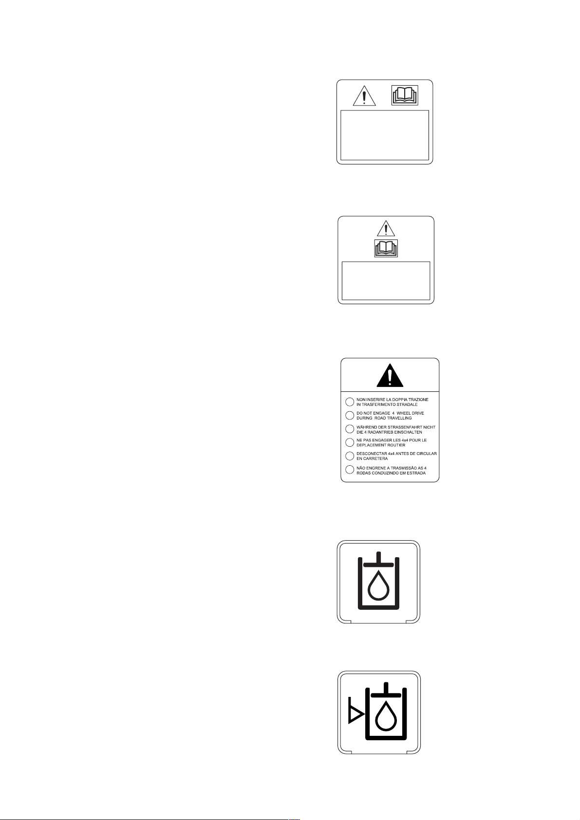
LOCK THE LOADER CONTROL
q When it is necessary to travel on roads, lock the loader con-
trol lever before starting.
CONNECT THE BRAKE PEDALS
q When the machine travels on roads, the brake pedals must
be connected with the apposite pin.
PRIMA DI PARTIRE PER IL
TRASFERIMENTO SU
STRADA BLOCCARE LA LEVA
COMANDO PALA!
42N-93-12460
RKA14770
DURANTE I TRASFERIMENTI
SU STRADA I PEDALI FRENO
DEVONO ESSERE COLLEGATI
CON APPOSITO SPINOTTO
42N-93-11110
RKA14780
DO NOT ENGAGE THE 4WD
q When the machine travels on roads, do not engage the
4WD.
HYDRAULIC OIL TOPPING UP
I
GB
D
F
E
P
37A-98-12210
42N-93-11120
RKA14790
RKA14800
HYDRAULIC OIL LEVEL
24
37A-98-12290
RKA14810
Page 27

HYDRAULIC OIL FILTER
REFUELLING
FUEL FILTER
SAFETY, NOISE AND VIBRATION PLATES
37A-98-12310
RKA14820
D
37A-98-12240
RKA14830
ENGINE LUBRICATING OIL FILTER
ENGINE AIR SUCTION FILTER
D
37A-98-12250
37A-98-12230
37A-98-12260
RKA14840
RKA14850
RKA14860
ENGINE COOLANT
37A-98-12340
RKA14870
25
Page 28
SAFETY, NOISE AND VIBRATION PLATES
COOLANT PRESSURE
TRANSMISSION OIL LEVEL
TRANSMISSION OIL FILTER
37A-98-12270
395-93-11440
RKA14880
RKA14590
POWER OUTLET
BOOM LOCK
SWING LOCK
395-93-11420
12 V
42N-93-11270
42N-93-11320
RKA14580
RKA14890
RKA14900
26
42N-93-11310
RKA14910
Page 29
ANCHORAGE POINT
EMERGENCY EXIT
BRAKE OIL
SAFETY, NOISE AND VIBRATION PLATES
42N-93-11360
RKA14920
42N-93-11260
RKA14930
E
K
O
B
R
A
I
L
DO NOT LIFT MORE THAN 1000 kg
L
I
O
K
E
SWL 1000 Kg
RKA14950
B
R
A
RKA14940
27
Page 30
SAFETY, NOISE AND VIBRATION PLATES
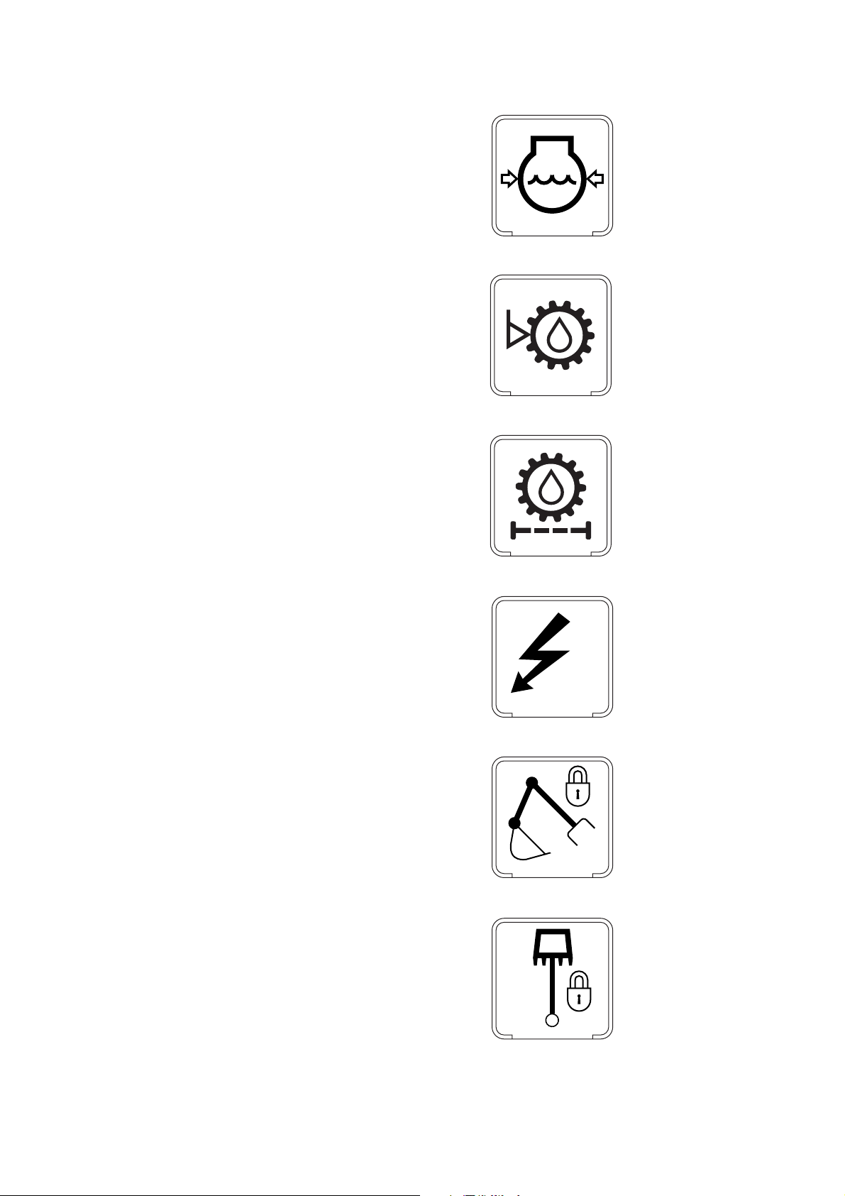
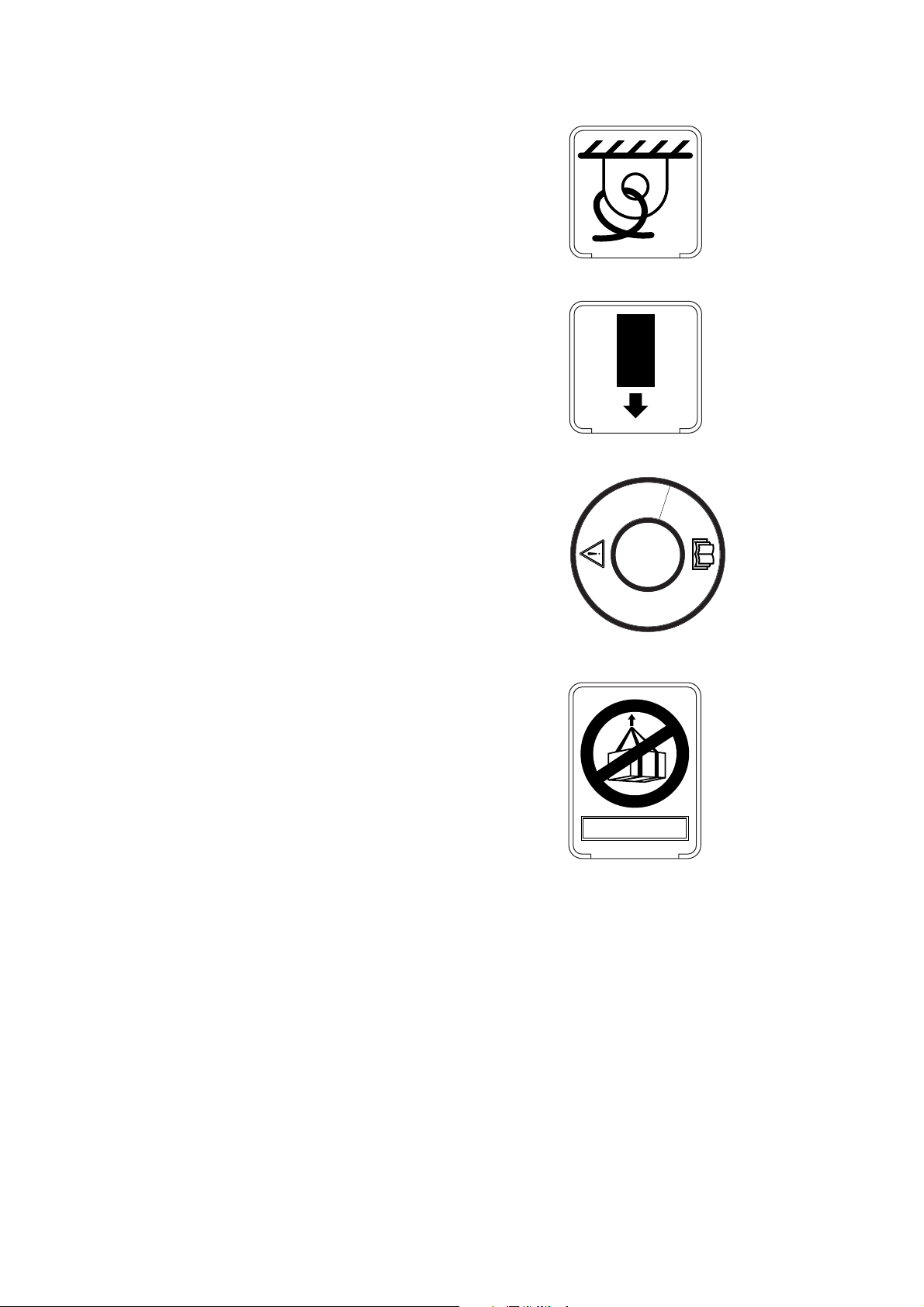
2.1.3 POSITION OF THE NOISE PLATES ON MACHINES WITH CAB
q The noise plates must always be legible and in good conditions; for this reason, if they are dirty with dust, oil or
grease, it is necessary to clean them with a solution made of water and detergent.
Do not use fuel, petrol or solvents.
q If the plates are damaged, ask for new ones to Komatsu or to your Komatsu Dealer.
q In case of replacement of a component provided with a noise plate, make sure that this plate is applied also on
the new piece.
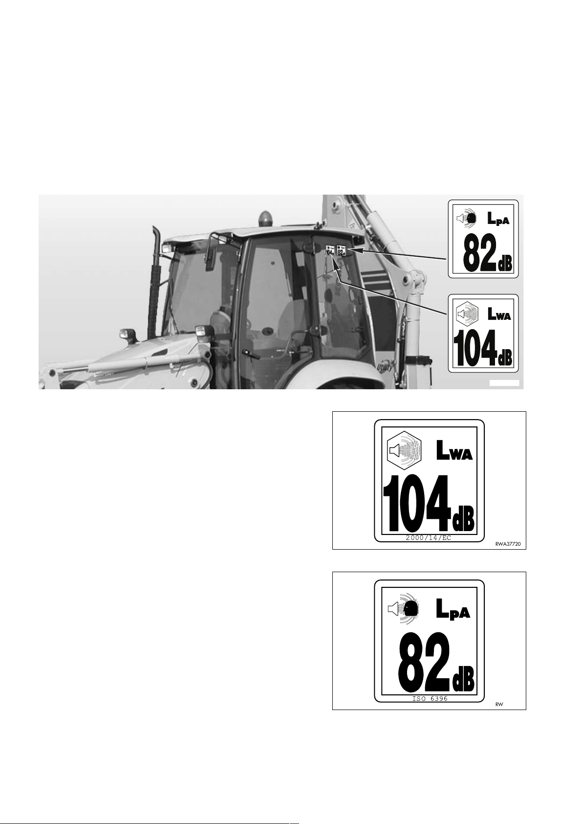
ISO 6396
NOISE OUTSIDE THE CAB
q This value indicates the noise level outside the machine and
refers to the noise perceived by persons in the vicinity of the
work area.
NOISE INSIDE THE CAB
q This value indicates the maximum noise level perceived by
the operator’s ears inside the cab when this is completely
closed.
2000/14/EC
2000/14/EC
RKAB4750
RWA37720
28
ISO 6396
RWA37730
Page 31

SAFETY, NOISE AND VIBRATION PLATES
2.1.4 VIBRATIONS TO WHICH THE OPERATOR IS SUBJECTED
q According to the results of the tests carried out to determine the vibrations transmitted to the operator by the ma-
chine, the upper limbs are subjected to vibrations lower than 2.5 m/sq.sec., while the seated part of the body is
subjected to vibrations lower than 0.5 m/sq.sec.
29
Page 32

GENERAL PRECAUTIONS
2.2 GENERAL PRECAUTIONS
2.2.1 GENERAL SAFETY RULES
q Only trained and authorized personnel can use the machine and perform maintenance operations.
q Follow all the safety rules, precautions and instructions when using the machine or performing maintenance op-
erations.
q When working with other operators or when the work site is often occupied by other operators, make sure that
everyone knows and understands all the signs described above and, in any case, that everyone works in such a
way as to be able to see the machine and to be visible to the operator.
2.2.2 SAFETY DEVICES AND GUARDS
q Make sure that all the guards and covers are in the correct position. Have guards and covers changed or re-
paired if damaged. Do not use the machine without guards, nor remove the guards when the engine is running.
q Always use the proper safety devices to lock the machine when parking and remember to fasten the safety belt.
q For the safety devices, see "3.1 SAFETY LOCKS".
q For the safety belt, see "3.5.6 SAFETY BELT".
q Do not remove the safety devices and always keep them in good operating conditions.
q Any improper use of the safety devices may result in serious injury or even death.
2.2.3 CLOTHING AND PERSONAL PROTECTION ITEMS
q Do not wear large or loose clothes, rings and watches and
do not approach the machine with loose long hair, since they
can get entagled in the moving parts of the machine and
cause serious personal injury or damage. Also avoid wearing clothes that are dirty with oil or fuel, since they catch fire
very easily.
q Wear a hard hat, goggles, safety shoes, mask, gloves and
headphones when operating the machine or performing
maintenance operations.
q Always wear safety goggles, a hard hat and heavy gloves if
your job involves scattering metal chips or minute materials;
these precautions are particularly useful when driving the
equipment connection pins with a hammer and when blowing compressed air into the air filter and the radiator to clean
them. During these operations, make also sure that no one
is standing or working near the machine without the necessary protection.
q When working for 8 hours with a noise level exceeding 90
dBA, it is necessary to use headphones or ear plugs and be
particularly careful, especially towards the end of the work
shift.
RWA00960
2.2.4 UNAUTHORIZED MODIFICATIONS
q Any modification made to the machine without the authorization of Komatsu can involve hazards.
q Before making a modification, consult your Komatsu Dealer. Komatsu declines any responsibility for injury or
damage caused by unauthorized modifications.
30
Page 33

2.2.5 LEAVING THE OPERATOR’S SEAT
q When leaving the operator’s seat, even if for a short time,
make sure that the machine is in a safe position. (See
"2.4.12 PARKING THE MACHINE").
q Before leaving the operator’s seat, carry out the following
operations in the sequence indicated below:
1 - Lower the equipment to the ground.
2 - Press the servo control locking button (LED on).
GENERAL PRECAUTIONS
NOTE
q On machines equipped with backhoe servo controls, all
movements are inhibited when the button is in locking position (LED on).
3 - Engage the safety lock of the mechanical controls.
4 - Apply the parking brake.
5 - Shift the reversing gear lever to the neutral position.
6 - Stop the engine.
If you have to go so far away that you will not be able to see
the machine, extract the ignition key.
RKAB2760
RKAB2780
RWA02000
RKAB2800
N
RKAB4820
31
Page 34

GENERAL PRECAUTIONS
2.2.6 GETTING ON AND OFF THE MACHINE
q Do not jump on or off the machine, both when it is at rest and
when it is moving.
q Always use the handles and the safety ladders to get on or
off the machine, and be very careful.
q Do not hold or rest on the steering wheel or the gearshift le-
ver.
q Both when getting on and when getting off the machine, al-
ways maintain three points of contact (holding or resting
points), in order to avoid losing your balance and falling
down.
q Tighten the handle and ladder connection screws if they are
loose and clean the handles and steps if they are dirty with
oil or grease. Carefully clean the cab floor if it is dirty with oil,
grease, mud or rubble.
RKAB2820
2.2.7 CHECKING THE REAR-VIEW MIRRORS
q Make sure that the rear-view mirrors are clean and correctly
positioned; they must allow the operator to see the rear of
the machine with no need to move the chest with respect to
the normal work position.
q If the rear-view mirrors should move or break during work,
stop the machine immediately and fasten or change them.
q Working without checking the area behind the machine is
dangerous, since the machine may hit persons who are incautiously standing in the work area, fixed obstacles or manoeuvring vehicles.
RWA18670
RWA00340
32
Page 35

2.2.8 PREVENTING FIRES DUE TO FUEL AND OIL
Fuel, oil and some types of antifreeze can be easily ignited if
they get in contact with a flame. Fuel is flammable and therefore very dangerous.
q Keep any naked flame away from flammable fluids.
q Stop the engine and do not smoke when refuelling.
q Top up with fuel and oil only after stopping the engine and in
well ventilated areas.
q Top up with fuel and oil in a well delimited area and do not al-
low unauthorized persons to approach.
q When refuelling, hold the fuel gun firmly and keep it con-
stantly in contact with the filler until you have finished, in order to avoid sparks due to static electricity.
q After topping up, tighten the fuel and oil safety caps securely.
q Do not fill the tank completely, in order to leave room for the
fuel to expand.
q If some fuel is inadvertently spilled, wipe it up immediately.
GENERAL PRECAUTIONS
RWA00970
2.2.9 PREVENTING BURNS
q If the engine coolant, the engine oil and the hydraulic oil are
hot, use heavy cloths and wear gloves, heavy clothing and
safety goggles before carrying out any check or touching the
hot parts.
q Before checking the coolant level, stop the engine and let
the fluid cool down.
If a check is necessary due to the overheating of the engine,
loosen the radiator cap slowly, to release any residual pressure before removing it. The hot fluid that spurts out may
cause serious burns.
q Before checking the engine oil and hydraulic circuit oil level,
stop the engine and let the oil cool down. The hot oil that
may be sprayed out of the tank may cause serious burns.
RWA00980
RWA00990
33
Page 36

GENERAL PRECAUTIONS
2.2.10 PREVENTING DAMAGE DUE TO ASBESTOS POWDER
q Asbestos powder can be hazardous to your health if it is in-
haled.
q If you handle materials containing asbestos fibers, keep to
the instructions given below:
1 - Do not use compressed air, but only exhaust fans to
clean the machine, and make sure that the room in which
you are working is properly ventilated.
2 - Use low-pressure water to abate dust when cleaning.
3 - If there is danger that there may be asbestos powder in
the air, operate the machine with the wind to your back
whenever possible.
4 - Even if the cab provides suitable protection, use an ap-
proved and homologated respirator.
5 - The powder gathered during the cleaning operations must
be wet and put in a sealed and marked container, so that
it can be safely disposed of according to the regulations in
force.
RWA01000
2.2.11 PREVENTING DAMAGE CAUSED BY THE WORK EQUIPMENT
q Do not stand within the operating radius of the work equip-
ment, even when the operator is on board the machine and
the engine is running.
q Do not stand or work under the arms or the articulations
when the arms are lifted, if you are not sure that the safety
locks have been duly engaged.
q Do not carry out any operation requiring the arms to be lifted,
if you are not sure that the locks are correctly positioned and
connected to the arms.
RWA01010
RWA01020
34
Page 37

GENERAL PRECAUTIONS
2.2.12 FIRE EXTINGUISHERS AND FIRST AID KIT
q Make sure that fire extinguishers have been provided and
check their position.
q Periodically make sure that the fire extinguishers are loaded
and that you know how to use them.
q Find out where the first aid kit has been located.
q Periodically make sure that the first aid kit contains the nec-
essary disinfectants, bandages, medicines, etc.
q It is necessary to know what to do in case of fire.
q Make sure that you have the phone numbers of the persons
RWA01030
or structures you may need to contact in case of an emergency at hand (both at the worksite and where maintenance
operations are performed).
2.2.13 PRECAUTIONS CONCERNING THE CAB STRUCTURE
q If the cab is inadvertently hit or the machine overturns during work, the cab may be damaged with consequent
reduction of its stiffness and of the safety that must be guaranteed to the operator (ROPS/FOPS).
Contact Komatsu or your Komatsu Dealer to have the cab structure and resistance checked in case of impact or
damage.
2.2.14 PRECAUTIONS CONCERNING THE EQUIPMENT
q When installing and using optional equipment, carefully read the relevant instruction manual and keep to the in-
dications given therein.
q Do not use optional or special equipment without the authorization of Komatsu or a Komatsu Dealer.
Installing and using any equipment not authorized by Komatsu may create safety problems and may have negative consequences on both the efficiency and life of the machine.
q Komatsu cannot be held liable for any injury, accident, product failure resulting from the installation and use of
unauthorized equipment.
35
Page 38

PRECAUTIONS TO BE TAKEN BEFORE STARTING THE ENGINE
2.3 PRECAUTIONS TO BE TAKEN BEFORE STARTING THE ENGINE
2.3.1 SAFETY ON THE WORK SITE
q Before starting the engine, thoroughly check the area for any
unusual condition of the ground due to which work may be
dangerous.
q Check the conditions of the ground at the work site and be-
fore starting the engine define the work plan and the best
and safest operating procedure.
q Level the ground surface as much as possible before carry-
ing out any operation.
q In case of work on the road, protect pedestrians and cars by
designating a person for work site traffic duty and install
fences around the work site.
q If water lines, gas lines, and telephone or high-voltage elec-
trical lines are located under the work site, contact the relevant utility company in order to find out their exact position or
to disconnect them until the end of the operations. Be careful
not to sever or damage any of these lines.
RWA00220
q Check the water depth and the force and flow direction of the
current before operating in water or on river banks.
2.3.2 FIRE PREVENTION
q Completely remove all wood chips, rubbish, paper and other
flammable materials that may have accumulated inside the
engine compartment, since they can cause fires.
q Check the fuel and hydraulic system pipes for leaks and if
necessary repair them. Wipe up any excess oil, fuel or other
flammable fluids.
q Make sure that fire extinguishers are available in the work
area.
2.3.3 PRECAUTIONS TO BE TAKEN FOR THE OPERATOR'S CAB
RWA01040
q Do not leave objects or tools lying around in the operator's cab. They may prevent the use of the brakes and
cause serious accidents.
q Keep the cab floor and the controls (steering wheel and levers) clean, by removing any trace of oil and grease
and, as far as the floor is concerned, remove any excess dirt (earth, stones, etc.).
q Check the safety belt and change it if it is broken or damaged. Replace any component only with homologated
parts available at Komatsu or its Dealers.
q Make always sure that the lock of the right door, which is considered the emergency door, is open.
36
Page 39

PRECAUTIONS TO BE TAKEN BEFORE STARTING THE ENGINE
2.3.4 ROOM VENTILATION
q Before starting the machine in confined or poorly ventilated
places, provide for proper ventilation or connect the engine
exhaust pipe to a suction duct. The engine exhaust gases
can be deadly.
RWA01050
2.3.5 CLEANING WINDOWS, MIRRORS AND LIGHTS - CHECKING THE WINDSHIELD WIPER BLADES AND THE BULBS
q Remove any trace of dirt from the cab windows and the lights and clean the rear-view mirrors; this will ensure
good visibility on the work area.
q Adjust the rear-view mirrors if they have moved, so that the operator seated in the driving position can clearly
see the area behind the machine.
If any window, light or mirror is damaged, change it.
q Make sure that the road lights, stop lights, direction indicators and work lights are properly working. If necessary,
change the faulty bulbs with new ones, making sure that their power is correct.
q Check the conditions of the windshield wiper blades; the scraping wire must be smooth, with no indentations and
attached to the rubber back of the blade.
In case of doubt on the efficiency of the scraping wire, change the blades.
37
Page 40

PRECAUTIONS TO BE TAKEN DURING WORK
2.4 PRECAUTIONS TO BE TAKEN DURING WORK
2.4.1 WHEN STARTING THE ENGINE
q Before getting on the machine, walk around it and check for people and objects that might be in the way.
q Do not start the engine if warning plates have been attached to the steering wheel or the control levers.
q When starting the engine, sound the horn as an alert signal.
q Start the engine and operate the machine only while seated with fastened safety belt.
q Do not allow anyone to get on the machine or enter the cab.
2.4.2 RULES FOR TRAVELLING ON ROADS
q The machine is equipped with multifunction safety locks that must be used both for maintenance operations and
road travel.
q When it is necessary to travel on roads, proceed as follows:
1 - Position the safety lock of the front loader so that the bucket is lifted from the ground, thus ensuring better vis-
ibility and the stability of the machine.
2 - Install the front bucket swing lock and secure it with the safety pins.
3 - Install the teeth protection casing on the front bucket.
4 - Lift the backhoe boom until engaging the safety coupling.
The arm and bucket must in any case be completely folded.
5 - The backhoe must be rotated and resting against the machine structure.
This is the only position homologated for road travel in Italy.
6 - For travelling with folded backhoe, the unit must be moved on its guide in such a way as to be positioned to-
wards the road centre, against the lock and with the bucket facing the road side.
7 - Fasten the backhoe with the swing lock pin.
8 - Connect the safety chains to prevent the accidental lowering of the stabilizers.
9 - Engage the safety locks of the loader and backhoe control levers.
For further information on their position, see "3.1 SAFETY LOCKS".
q When it is necessary to travel on roads, the four-wheel drive must be disengaged and the brake pedals must be
connected with the appropriate pin.
q When travelling on roads, keep to the rule of the road and operate the flashing light positioned on top of the cab.
q When travelling on roads, keep the work lights off.
IMPORTANT
q In any case, keep to the traffic rules in force.
38
Page 41

PRECAUTIONS TO BE TAKEN DURING WORK
2.4.3 HAND SIGNALS
WARNING
q When it is necessary to position loads, make excavations or move the machine with a reduced field of vi-
sion, the operator must be helped by another person (signalman) who should stand on the ground and
give signals to indicate the manoeuvres to be carried out according to the specific instructions provided
for by the relevant regulations.
q No movement or operation may be carried out if the signals have not been clearly understood by the op-
erator and the signalman.
q When additional instructions different from those defined by the hand signalling system are necessary,
these must be agreed upon by the two operators before starting the job.
q Only one person must be entrusted with giving signals.
q The operator must make sure that the signalman is always within his field of vision and follow all his sig-
nals.
The use of hand signals serves to direct the lifting, handling and positioning of the loads lifted by the work equipment. Hand signals can also be used during digging operations or when the machine travels, if the field of vision of
the operator is reduced. The direction of movement of the hands and arms in relation to the machine must define
the signal, independently of the position of the signalman. Hand signals must be given following the indications below.
1 - LIFT THE LOAD VERTICALLY
One forearm in vertical position and forefinger pointing
upwards: turn the hand making small circles.
2 - LOWER THE LOAD VERTICALLY
One arm down and forefinger pointing downwards: turn
the hand making small circles.
RKA15140
RKA15150
39
Page 42
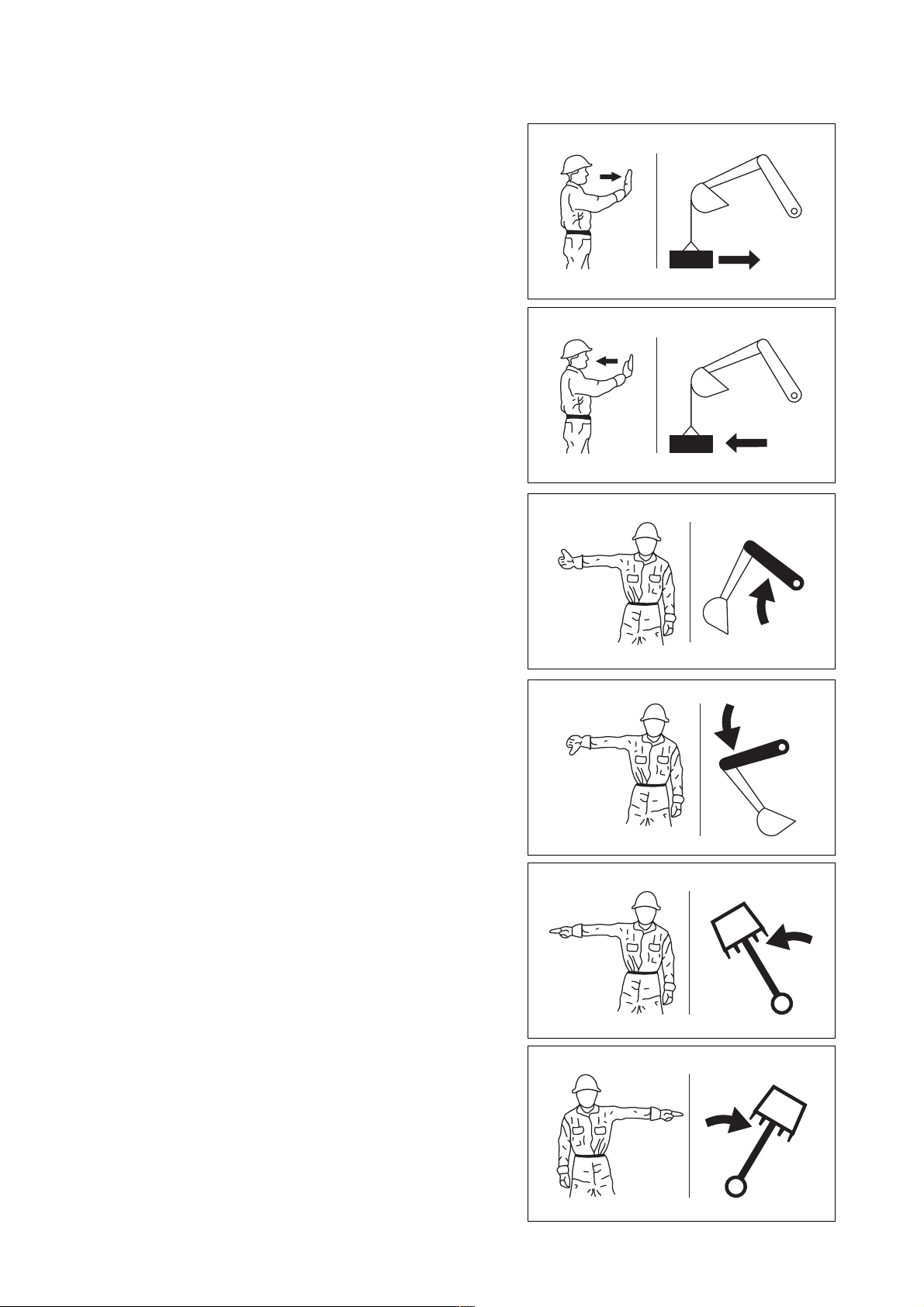
PRECAUTIONS TO BE TAKEN DURING WORK
3 - MOVE THE LOAD AWAY IN HORIZONTAL DIRECTION
One arm outstretched and hand in vertical position with
the palm facing towards the load to be moved away: move
the hand in the direction of the movement to be carried
out.
4 - BRING THE LOAD NEARER IN HORIZONTAL DIREC-
TION
One arm outstretched and hand in vertical position with
the palm facing towards yourself: move the hand in the direction of the movement to be carried out.
5 - LIFT THE BOOM
One arm laterally outstretched in horizontal position and
clenched fingers: point the thumb upwards.
RKA15160
RKA15170
6 - LOWER THE BOOM
One arm laterally outstretched in horizontal position and
clenched fingers: point the thumb downwards.
7 - SWING THE BOOM
One arm laterally outstretched in horizontal position: point
the forefinger towards the desired swing direction.
8 - SWING THE BOOM
One arm laterally outstretched in horizontal position: point
the forefinger towards the desired swing direction.
RKA15180
RKA15190
RKA15200
40
RKA15210
Page 43

9 - FOLD THE ARM
With both fists clenched, point the thumbs inwards.
10 - EXTEND THE ARM
With both fists clenched, point the thumbs outwards.
11 - FOLD THE BUCKET
Keep one hand still and closed. Rotate the other hand
vertically with the forefinger pointing towards the closed
hand.
PRECAUTIONS TO BE TAKEN DURING WORK
RKA15220
RKA15230
12 - OPEN THE BUCKET
Keep one hand still and open. Rotate the other hand vertically with the forefinger pointing towards the open hand.
13 - TRAVEL WHILE STEERING
Lift the forearm corresponding to the inner steering side
with clenched fist. Rotate the other fist vertically indicating
the wheel’s turning direction.
14 - TRAVEL WHILE STEERING
Lift the forearm corresponding to the inner steering side
with clenched fist. Rotate the other fist vertically indicating
the wheel’s turning direction.
RKA15240
RKA15250
RKA15260
RKA15270
41
Page 44

PRECAUTIONS TO BE TAKEN DURING WORK
15 - TRAVEL STRAIGHT AHEAD
Rotate the fists vertically indicating the turning direction of
the wheels.
16 - TRAVEL STRAIGHT AHEAD
Rotate the fists vertically indicating the turning direction of
the wheels.
17 - DISTANCE TO BE COVERED
Hands raised and palms facing inwards: move the hands
laterally indicating the distance to be covered.
RKA15280
RKA15290
18 - CARRY OUT THE MOVEMENTS SLOWLY
One hand still in front of the hand that indicates the movement to be carried out. (The figure represents the “lift
slowly” signal).
19 - STOP
One arm outstretched laterally, hand open and palm facing downwards: move the arm forwards and backwards.
20 - EMERGENCY STOP
Both arms outstretched laterally in horizontal position,
hands open and palms facing downwards: move both
arms forwards and backwards.
RKA15300
RKA15310
RKA15320
42
RKA15330
Page 45

21 - STOP THE ENGINE
Pass thumb or forefinger across the throat.
22 - RETRACT THE TELESCOPIC ARM
One forearm lifted forwards and clenched fingers: point
the thumb in the direction of the movement to be carried
out.
23 - EXTEND THE TELESCOPIC ARM
One forearm lifted forwards and clenched fingers: point
the thumb in the direction of the movement to be carried
out.
PRECAUTIONS TO BE TAKEN DURING WORK
RKA15340
RKA15350
RKA15360
43
Page 46

PRECAUTIONS TO BE TAKEN DURING WORK
2.4.4 CHECKS FOR TRAVELLING IN REVERSE
q When operating in areas that may be hazardous or where
visibility is poor, designate a person to direct the movements
of the machine and traffic on the work site.
q Before moving the machine, sound the horn to warn the per-
sons standing or working in the area.
q There are blind spots behind the machine, which cannot be
seen through the rear-view mirrors and where someone may
be standing.
Therefore, it is necessary to make sure that there is no one
behind the machine before travelling in reverse.
On request the machine can be equipped with an acoustic
alarm (1) for travelling in reverse; before starting to travel in
reverse, make sure that the acoustic alarm is functioning
perfectly.
See "3.3.6 pos. 1 - REVERSING GEAR LEVER".
RWA00340
1
2.4.5 MOVING THE MACHINE
q When moving the machine, position the front bucket at about
30–40 cm from the ground; this position makes it possible to
evaluate the space required for the movements more precisely and at the same time ensures the stability of the machine.
q If the front bucket control lever is to be used during travel,
avoid moving it abruptly; sudden manoeuvres change the attitude of the machine and make driving difficult.
q When travelling on rough ground, keep the speed low and
avoid sudden movements of the bucket arm.
q If the machine has to overrun an obstacle, keep the front
equipment as close to the ground as possible and travel at
low speed, in order not to overload the axles and tyres.
RKAB5830
30-40 cm
RKA13510
44
Page 47

2.4.6 WORKING ON SLOPES
q Operations on slopes and on river or lake banks with damp
ground may result in the tipping over or slipping of the machine.
q Do not work with the bucket downward with respect to the
tractor.
q On hills, banks or slopes, keep the bucket very close to the
ground (20–30 cm from the ground) and in case of emergency quickly lower it to the ground to help the machine stop.
Do not change direction and avoid travelling obliquely when
working on slopes. It is advisable to go down or up to a flat
place to perform these operations.
q Do not travel on wet grass or thick layers of leaves: if the
machine moves obliquely in these conditions, it may slip.
q Before working on a slope, always check the efficiency of
the brakes, engage a low gear and the four-wheel drive.
q Do not travel down slopes in neutral; you may lose control of
the machine and cause serious injuries and even death.
q Avoid disengaging the gearshift with the push button posi-
tioned on the loader control lever.
q When travelling down a slope, engage a low gear, so that
the braking action of the engine is used to hold the machine,
with no need to overload the brakes. Avoid disengaging the
gearshift with the push button positioned on the gearshift
control lever.
q When the fuel level indicator reaches the red reserve area
during work on a slope, immediately provide for refuelling;
due to the inclination of the machine, the engine may suck in
air and suddenly stop, which represents a grave risk for the
safety of the operator and of the persons standing before the
machine.
PRECAUTIONS TO BE TAKEN DURING WORK
20-30 cm
RKA13520
WRONG
RKA13540
CORRECT
q If the engine should stop all of a sudden, immediately lower
the bucket to the ground, brake and apply the parking brake.
RKA13650
45
Page 48

PRECAUTIONS TO BE TAKEN DURING WORK
2.4.7 PREVENTING ELECTROCUTION
q Digging operations near overhead electric lines are extreme-
ly dangerous and they may also cause death due to electrocution; for this reason, when working near overhead
electrical lines, always respect the minimum safety distances prescribed by the competent authorities and by the accident-prevention rules in force.
q As far as underground long-distance lines are concerned,
the minimum distance depends on the covering of the ducts
in which the cables are laid.
q The basic safety precautions to be taken to prevent this risk
are the following:
1 - Wear shoes with thick rubber or leather soles.
2 - Request the aid of another person who can warn you if
the machine gets too close to the electric line.
3 - Operate at low speed.
4 - Get acquainted with the behaviour rules to be followed in
case of electrocution.
5 - Keep the phone number of the electric energy company
and of the nearest hospital at hand.
RWA04900
q If the work equipment gets accidentally entangled in the ca-
bles, the operator must not leave the cab until the electricity
company has insulated the line.
q When carrying out this kind of operations, warn everyone
standing in the work area to maintain a safety distance from
the machine and the work equipment.
q Ask the electricity company in advance what are the voltage
of the cables and the minimum safety distance.
DANGER
q The minimum distances from overhead lines can vary in
the different countries, according to the climate and to
the humidity percentage in the air.
Indicatively, the distances indicated in the table should
be respected.
Cable voltage Min. safety distance
1.0 kV (
distribution line)5 m
6.6 kV (2–3
insulators)5.2 m
46
33 kV (
66 kV (
154 kV (
275 kV (
min. 3 insulators)5.5 m
min. 6 insulators)6 m
min. 10 insulators)8 m
min. 19 insulators) 10 m
Page 49

PRECAUTIONS TO BE TAKEN DURING WORK
2.4.8 VISIBILITY
q Switch on the headlights or the work lights as soon as visibility decreases.
q If visibility decreases due to mist, smoke or heavy rain, stop the machine in a safe position and wait for the
weather to improve until visibility becomes acceptable.
2.4.9 WORKING ON ICY OR SNOW-COVERED SURFACES
q If the ground is icy or covered with snow, the response of the machine to the movements of the steering wheel
may not be precise.
To reduce the risks connected with poor manoeuvrability, proceed as follows:
1 - Engage the four-wheel drive.
2 - Travel using the accelerator smoothly and gradually.
3 - Brake smoothly and only after having slowed down by using the engine deceleration as much as possible.
4 - Absolutely avoid any sudden braking, abrupt acceleration and sudden steering with short steering radius.
q If the machine is used to clear snow or as snowplough on roads (installing the specific optional equipment and
even chains, if necessary), be careful to the road shoulders and to any object/obstacle buried in the snow (wayside posts, milestones, signs just above the asphalt, etc.).
2.4.10 PREVENTING DAMAGE CAUSED BY THE WORK EQUIPMENT
q When working in tunnels, galleries, under electric cables or other ducts (air, telephone lines) and wherever the
height is limited, proceed with the greatest care to prevent the bucket or arms and the backhoe bucket from
causing any damage.
2.4.11 WORKING ON LOOSE GROUND
q Avoid operating the machine too close to the edge of cliffs, overhangs and deep ditches.
These areas may collapse, making the machine fall down or tip over and this could result in serious injury or
even death.
Remember that after heavy rain or earthquakes these dangerous conditions usually get worse.
q The earth laid near ditches is loose and can easily collapse due to the weight or vibrations of the machine.
Be extremely careful: always close the cab doors and fasten the safety belt.
47
Page 50

PRECAUTIONS TO BE TAKEN DURING WORK
2.4.12 PARKING THE MACHINE
q Park the machine on firm and level ground. If this is not pos-
sible and it is necessary to park on a slope, position the machine with the front bucket directed downwards and carry out
the following operations:
1 - While keeping the machine stopped with the brakes, ap-
ply the parking brake.
2 - Dump the front bucket to the unloading position and lower
the arms until the teeth are driven into the ground.
3 - Carry out the same operations with the backhoe bucket.
4 - Stop the engine.
5 - Position wedges or safety blocks under the front and rear
wheels.
q Always rest the work equipment on the ground; if it is neces-
sary to park with lifted arms, make sure that the safety locks
are engaged.
q Always engage the control lever safety locks.
NOTE
q The servo control locking button inhibits also the movements
of the backhoe when this is equipped with servo controls.
q When leaving the machine, apply the parking brake, make
sure that the cab windows are closed, remove the ignition
key and finally lock the doors.
RKA13750
RKA13760
q If it is necessary to park on public roads, provide for signal-
ling the presence of the machine according to the local regulations in force (signalling fires, fences, road works ahead,
alternated direction and direction signs, etc.).
RKAB2800
RKAB2760
RKAB2780
48
Page 51

TRANSPORTING THE MACHINE ON OTHER VEHICLES
2.5 TRANSPORTING THE MACHINE ON OTHER VEHICLES
2.5.1 LOADING AND UNLOADING THE MACHINE
q Loading and unloading the machine on-off a motor vehicle
always involves potential hazards. Proceed with extreme
care.
q The loading and unloading of the machine on-off the means
of transport must be carried out on a flat surface and at a
safety distance from the edges of ditches or from the road
side.
q If the vehicles used have not been appositely equipped, put
support blocks under the ramps, in order to avoid any bending.
q Always lock the wheels of the transporting vehicle with
wedges.
q Always use ramps that are sufficiently wide and can support
the weight of the machine. The longitudinal axes of the
ramps must be parallel to each other and perpendicular to
the loading side board and their distance must be suitable
for the tread of the machine.
q Make sure that the ramps are securely positioned and fas-
tened to the loading board and that they have the same
length.
Ramps
Max.15˚
Blocks
Blocks
RWA00240
q Position the ramps with a maximum inclination of 15°.
q Make sure that the ramp surface is clean and there is no
trace of grease, oil, soil and ice; remove dirt from the wheels
before starting to load the machine on the vehicle.
q The machine must be loaded on the vehicle with the bucket
directed forwards, that is, in the direction of advancement of
the vehicle.
q Do not correct the trajectory of the machine on the ramps. If
necessary, get down the ramps and start the operation
again.
q After loading the machine, block its wheels with wedges and
secure it with tie-downs or chains that prevent even any
sideward shift (see "3.9 TRANSPORTING THE MACHINE
ON OTHER VEHICLES").
2.5.2 TRANSPORT
CAUTION
q During transport, the machine must be secured to the vehicle, with closed doors and windows.
q Define the route to be followed, taking in consideration the width, height and weight of the transport means and
of the machine.
Make sure that the dimensions of the machine are compatible with the road and any galleries, subways, bridges,
electric and telephone lines, etc.
q Keep to the regulations in force regarding the permissible width, height, weight of the machine and the transport
speed.
49
Page 52

BATTERY
2.6 BATTERY
2.6.1 PREVENTING RISKS THAT MAY BE DUE TO THE BATTERY
q Electrolytic batteries contain sulphuric acid, which can cause
burns. It can also corrode clothing and make holes in it. In
case of contact with battery acid, immediately wash the involved part with plenty of water.
q Battery acid may cause blindness if it comes in contact with
the eyes.
If acid accidentally gets into your eyes, wash them immediately with plenty of water and consult a doctor without delay.
q If you accidentally swallow battery acid, drink a large quanti-
ty of water or milk, beaten egg white or vegetable oil and in
any case anti-acid substances like magnesia, bicarbonate,
etc., call a doctor or a poison treatment centre immediately.
q Always wear safety goggles when working on batteries.
q Batteries produce hydrogen, which is highly explosive and
can be easily ignited with small sparks or naked flames.
RWA01060
WRONG
q Before working with batteries, stop the engine and remove
the ignition key.
q Avoid short-circuiting the battery terminals through acciden-
tal contact with metal objects or tools or through the inversion of the terminals.
q Tighten the battery terminals securely. Loose terminals may
generate sparks and even cause the explosion of the battery.
2.6.2 STARTING WITH BOOSTER CABLES
q When starting the machine with booster cables, always wear
safety goggles.
q When starting the engine by means of another machine,
avoid any contact between the two machines.
q Be sure to connect the positive cable (+) first and then the
negative or earth cable (-) when connecting the booster cables. After the start, disconnect first the negative or earth (–)
cable and then the positive cable (+).
RWA01080
RWA01180
q Connect the batteries in parallel: positive to positive and
negative to negative.
q When connecting the earth cable to the frame of the ma-
chine to be started, operate as far as possible from the battery (see "3.15.3 IF THE BATTERY HAS RUN DOWN").
q Do not attempt to start the engine by causing a short-circuit
with the terminals of the starter (see "2.8.14 PRECAUTIONS
CONCERNING THE STARTER").
50
RWA01190
Page 53

PRECAUTIONS FOR EMERGENCY RECOVERY
2.7 PRECAUTIONS FOR EMERGENCY RECOVERY
q The draw hooks must be used only for the first aid and not
for towing the machine.
q Before moving the machine, make sure that the gearshift le-
ver is in neutral and disengage the four-wheel drive.
q Incorrect manoeuvres may cause serious damage, injury
and even death.
q To move the machine, use properly dimensioned steel ca-
bles; do not use worn cables or cables with broken strands
(A), twisted cables (B), deformed cables (C).
q During the removal, no one should be allowed to get near
the machines or the cable.
q Do not get astride the cable.
q Move the machine only as far as necessary to allow the re-
quired repairs to be carried out.
q Do not remove the machine in any way other than that indi-
cated in paragraph "3.15.1 HOW TO REMOVE THE MACHINE".
F
RKAB2830
CAUTION
q The maximum applicable force for each draw hook is F =
4854 kg.
q Use cables of the same length and pull continuously,
without jerking movements.
q The drawing force must be parallel to the machine axis
(advancement direction), in such a way as to avoid the
application of sideward forces on the draw hooks.
F
RKAB2840
RWA05380
51
Page 54
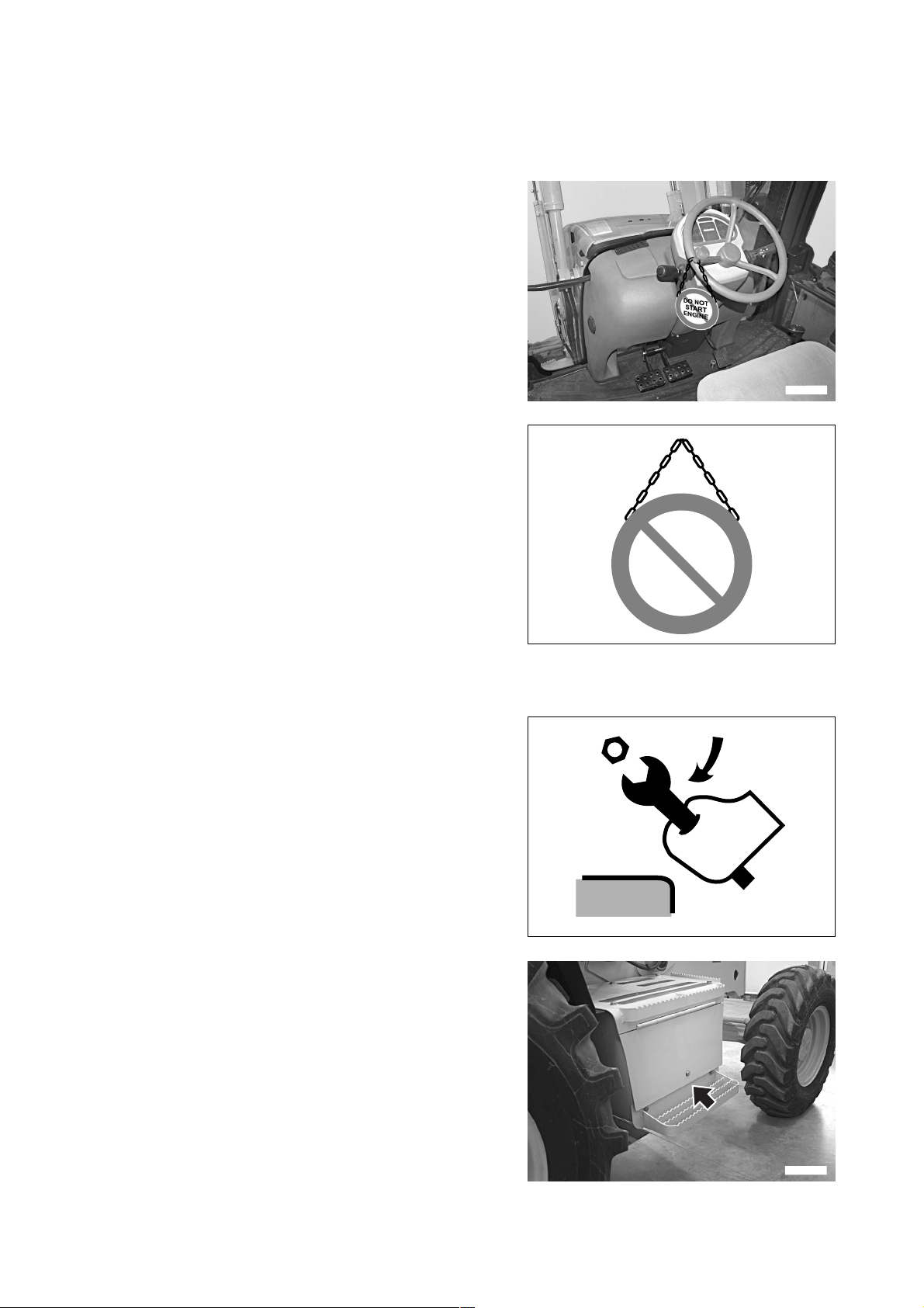
PRECAUTIONS TO BE TAKEN DURING MAINTENANCE
2.8 PRECAUTIONS TO BE TAKEN DURING MAINTENANCE
2.8.1 WARNING PLATES
q Before starting any maintenance operation, position the ma-
chine on firm and level ground, engage the safety locks of
the equipment and of the controls, stop the engine and apply
the parking brake.
q If anyone starts the engine and operates the control levers
while the operator is servicing the machine, this may result
in serious injury or even death.
q To avoid these risks, always attach warning plates to the
steering wheel, to the control levers and to the ignition key
before performing any maintenance operation; if necessary,
attach additional warning tags also around the machine and
in particular on the cab door handles.
RKAB4910
2.8.2 TOOLS
q Use only the tools supplied together with the machine and
high-quality tools suitable for the tasks to be performed.
q Do not use worn, damaged, low-quality tools or tools that are
not suitable for the tasks to be performed, in order to avoid
any personal injury.
q After use clean the tools carefully and store them in the com-
partment situated in the right access platform.
DO NOT
START
ENGINE
RWA01210
RWA01310
52
RKAB2770
Page 55

PRECAUTIONS TO BE TAKEN DURING MAINTENANCE
2.8.3 PERSONNEL
q Any maintenance operation must be carried out exclusively by authorized and duly trained personnel; specific
and personal protection measures must be adopted when grinding, welding and when using sledges or heavy
hammers.
q When assembling the equipment or cylinder connection pins, use wooden, plastic or in any case not excessively
hard tools to check the centering of the holes.
Do not use your fingers, since you run the risk of cutting them off.
2.8.4 EQUIPMENT
q The normal or special equipment that must be installed on
the machine or that have been removed must be stored in a
safe place and positioned in such a way as to prevent them
from falling down.
If they fall on someone, they may cause serious bodily harm.
q When assembling or removing any equipment, make sure
that the ropes and the lifting hook are in good conditions and
properly dimensioned for the load to be lifted.
RWA01320
2.8.5 WORKING UNDER THE MACHINE
q Before performing service or repairs under the machine, al-
ways lower the work equipment to the ground or in any case
lower it as much as possible.
q Always lock the tyres of the machine securely.
q Avoid working under the machine if it isn’t properly support-
ed.
RWA02520
53
Page 56

PRECAUTIONS TO BE TAKEN DURING MAINTENANCE
2.8.6 KEEPING THE MACHINE CLEAN
q Spilled oil or grease, scattered tools or broken pieces are
dangerous, because they may cause someone to slip or trip.
Always keep the machine and the worksite clean and tidy.
q To clean the machine, use a pressurized jet of warm water or
steam and the specific detergents available on the market.
Do not use diesel oil, oil or solvents, since the former leave
an oily coat that favours the sticking of dust, while the latter
(even if weak) damage the painted surfaces and therefore
facilitate rusting.
q While cleaning the machine, keep the pressurized jet at a
minimum distance of approx. 60 cm, in order to avoid damaging the warning plates and the pictograms.
If the plates are damaged, request Komatsu or your Komatsu Dealer to send you spare plates and change them.
q Water into the electric system provokes the oxidation of the
contacts and may hinder the start of the machine or even
make it start suddenly and abruptly. For this reason, avoid
using water or steam jets to clean sensors, connectors or
the inside of the operator's cab.
RWA01330
2.8.7 USE OF THE ENGINE DURING MAINTENANCE
q During maintenance operations, run the engine only when indispensable. If the engine must be running (for ex-
ample, when checking the functionality of the alternator), it is advisable that someone remains seated in the driving position, so that the engine can be stopped whenever necessary.
q During maintenance operations with running engine, neither move the control locking devices from the “lock” po-
sition, nor change the position of the gearshift lever.
Service personnel must not move any control lever.
q When carrying out maintenance operations, do not touch the moving parts of the machine and avoid wearing
large and loose clothes.
2.8.8 PERIODICAL CHANGE OF THE SAFETY RELATED PARTS
q Periodically change the following components, which are important for safety and fire prevention:
Fuel system: fuel delivery and return pipes.
Hydraulic system: main delivery pipes of the hydraulic pump.
Hydraulic system: work circuit pipes from the distributor to the hydraulic cylinders.
Safety belt.
q Even if they seem to be in good conditions, these components must be periodically changed with new ones.
In fact, these components tend to deteriorate over time.
q If one of these parts is defective, change or repair it even if the prescribed change interval has not elapsed yet.
(See "4.6 PERIODICAL CHANGE OF THE SAFETY RELATED COMPONENTS").
54
Page 57

2.8.9 STOP THE ENGINE BEFORE CARRYING OUT ANY MAINTENANCE
OPERATION OR INSPECTION
q Stop the machine only on firm and level ground and stop the
engine before carrying out any maintenance operation or inspection.
q If it is necessary to have the engine running during mainte-
nance, engage the safety LOCKS of the equipment control
levers, apply the parking brake and carry out any maintenance operation with the help of another person; an operator
must remain on board and the words to be used during the
operation must be agreed upon.
NOTE
q The servo control locking button inhibits also the movements
of the backhoe when this is equipped with servo controls.
q The maintenance personnel must be very careful not to
touch any moving part of the engine.
PRECAUTIONS TO BE TAKEN DURING MAINTENANCE
RWA02000
RKAB2760
RKAB2780
RKAB2800
55
Page 58

PRECAUTIONS TO BE TAKEN DURING MAINTENANCE
2.8.10 RULES TO BE FOLLOWED DURING FUEL OR OIL TOPPING UP
q Spilled fuel or oil make the ground slippery and may cause
accidents; clean any dirty area carefully and without delay.
q Always tighten the fuel tank and hydraulic oil tank safety
caps securely.
q Do not use fuel to clean any part of the machine that is dirty
with oil or dust.
q Always top up the fuel and oil tanks in properly ventilated ar-
eas and refrain from smoking.
q When refuelling, hold the fuel gun firmly and keep it con-
stantly in contact with the filler until you have finished, in order to avoid sparks due to static electricity.
q Do not fill the tank completely, in order to leave room for the
fuel to expand.
RWA00970
2.8.11 CHECKING THE COOLANT LEVEL IN THE RADIATOR
q Let the engine and the radiator cool down before checking
the coolant level in the radiator.
q If it is necessary to remove the cap with hot engine, wear
suitable clothes and protection and loosen the cap slowly, in
order to release the pressure gradually.
2.8.12 USING LAMPS
q When checking the fuel, oil, coolant or battery electrolyte
levels, always use homologated explosion-proof lamps.
Unsuitable lamps may cause fires or explosions.
RWA00980
RWA01340
56
RWA01350
Page 59

PRECAUTIONS TO BE TAKEN DURING MAINTENANCE
2.8.13 PRECAUTIONS CONCERNING THE BATTERY AND THE ALTERNATOR
q When repairing the electrical system, disconnect the battery
in order to stop the flow of current.
IMPORTANT
q Disconnect first the negative cable (-) and then the posi-
tive cable (+).
At the end of the operation, reconnect first the positive
cable (+) and then the negative cable (-).
q If electrical welding operations are to be carried out on the
machine, it is necessary to disconnect the battery and also
the alternator.
REMOVAL
12
RWA01370
RKAB2850
2.8.14 PRECAUTIONS CONCERNING THE STARTER
q Start the engine only when correctly seated in the driving po-
sition.
q Do not attempt to start the engine by causing a short-circuit
with the terminals of the starter. This may cause fires, serious injury and even death in case of sudden or accidental
movements of the machine.
RWA04890
RKAB2860
57
Page 60

PRECAUTIONS TO BE TAKEN DURING MAINTENANCE
2.8.15 HANDLING HIGH-PRESSURE PIPES
q Do not bend high-pressure pipes or rub them with sharp or abrasive objects.
Do not use any bent or cracked pipes or hoses that were previously rejected because of leaks or fastening defects, since they may burst during use.
q Always repair or replace any loose or faulty fuel or oil pipe. Any leakage of fuel or oil may cause fires.
2.8.16 PRECAUTIONS TO BE TAKEN
WHEN WORKING ON HIGH- PRESSURE SYSTEMS
q Do not forget that the work equipment circuits are always un-
der pressure; for this reason, when it is necessary to add or
drain hydraulic oil, or to service or inspect the hydraulic circuit, it is advisable to lower the equipment to the ground and
completely release the pressure and also the residual pressure present in the tank.
q For this reason, always wear goggles and thick gloves dur-
ing the inspections and use a piece of cardboard or a sheet
of plywood to check for oil leakages.Small leakages from
pipes under pressure and the resulting jets are extremely
dangerous, since they can perforate the skin and get in the
blood circulation or injure the eyes.
q If you are struck by a jet of high-pressure oil or are injured,
even if slightly, consult a doctor without delay.
DANGEROUS!
RWA01480
CORRECT
RWA01580
2.8.17 PRECAUTIONS FOR MAINTENANCE WORK INVOLVING HIGH
TEMPERATURES AND PRESSURES
q When the machine is stopped at the end of operations, the
engine coolant, the oil and all the components are hot and
the hydraulic circuits are under pressure.
In these conditions, if the coolant, the hydraulic oil or the engine oil are to be drained in order to change them or the filters, there are serious risks of injury and burns.
Wait for the temperature to lower within the normal operating
range (40–45) before carrying out the maintenance operations in accordance with the procedures indicated in the relevant sections of this manual.
58
RWA00990
Page 61

2.8.18 HYDRAULIC ACCUMULATOR
The hydraulic accumulator contains pressurized nitrogen.
When carrying out any operation on the accumulator, proceed
with the utmost care, in order to avoid explosions and consequently serious injury and even death.
For this reason, keep to the following instructions:
q do not remove the accumulator;
q do not use sparks or naked flames;
q do not make holes in the accumulator, do not weld or use ox-
yhydrogen flames;
q do not hit or press the accumulator;
q when disposing of the accumulator, take care to release the
gas it contains. Have this operation carried out only by a Komatsu Dealer.
2.8.19 COOLING FAN AND FAN BELT
q Be careful to the revolving parts and do not allow anyone to
get too close to these components, since clothes or parts of
the body may get caught into them.
q If hands, clothes, or tools become entangled in the fan
blades or the fan belt, they may be cut off, torn or seriously
injured/damaged; for this reason, avoid touching any revolving part.
PRECAUTIONS TO BE TAKEN DURING MAINTENANCE
RKA12540
2.8.20 WASTE MATERIALS
q Do not dispose of used oil in the sewer system, rivers, etc.
q Always put used oil in containers. Do not drain used oil di-
rectly on the ground.
q Keep to the laws and regulations in force when disposing of
harmful substances such as oil, fuel, solvents, used filters,
gaskets, electric wires and batteries.
WARNING
q Oils, filters, coolant, gaskets, electric wires and batter-
ies are considered special waste and must be collected
and disposed of according to the regulations in force.
q The combustible material of some components may be-
come extremely dangerous if it burns. For this reason,
avoid any contact of burnt material with your skin or
eyes and do not inhale the fumes produced.
RWA01660
RWA01670
59
Page 62

PRECAUTIONS TO BE TAKEN DURING MAINTENANCE
2.8.21 PRECAUTIONS CONCERNING TECHNOPOLYMERS AND ELASTOMERS
DANGER
q Some components of the machine contain polymers and elastomers (Viton sealing rings, Teflon rings,
piston seals made of fluoroelastomers, electric cable insulating materials, etc.).
At room temperature and up to approximately 200°C these materials can be handled without taking any
precautions, since they are completely inert.
However, if these materials are burnt, they release highly toxic gases.
Once these materials have cooled down, they must be collected in tight bags, using heavy waterproof
gloves; gloves and materials must be disposed of in a differentiated manner in compliance with the laws
in force.
The contaminated part of the machine must be washed with highly alkaline detergents and then with a
solution made of detergent and water.
q Avoid burning seals, electric cables, sealing rings.
q Dispose of elastomeric and polymeric waste according to
the regulations in force.
q Do not touch any burnt elastomeric or polymeric waste and
in case of accidental burning avoid inhaling the toxic gases
produced.
q In case of contact with the skin, immediately rinse with a so-
lution made of water and an alkaline detergent for about 30
minutes and then contact a poisoning treatment center without delay.
RKA13780
2.8.22 PRECAUTIONS TO BE TAKEN WHEN INFLATING THE TYRES
q Always bear in mind that tyres can burst while being inflated,
causing serious accidents.
q Before inflating the tyres, always check the wheel rims and
the tyre sidewalls and tread for dents, cuts, broken plies or
other defects.
q Have the tyres checked and serviced by specialized person-
nel.
q Inflate the tyres using a protection structure and a pneumatic
inflating gun with extension complete with pressure gauge.
q Make sure that there is nobody in the vicinity before starting
to inflate a tyre. Stand beside the tyre to inflate it.
q Do not exceed the inflation pressures prescribed for the sin-
gle types of tyre and make sure that all the tyres have the
same pressure.
RWA01680
60
Page 63

2.8.23 PRECAUTIONS FOR THE INSTALLATION OF THE EXHAUST SYSTEM TAILPIPE
PRECAUTIONS TO BE TAKEN DURING MAINTENANCE
2
q When the machine is stopped at the end of work, the ex-
haust pipe (1) and the tailpipe (2) are very hot. In these conditions, if any maintenance operation has to be carried out,
the operator runs the risk of being burned or injured.
Carry out any maintenance operation only when these parts
have cooled down and in any case always use thick gloves.
q Pay the utmost attention when installing the tailpipe (2) on
the exhaust pipe (1), since the former must be positioned
correctly with the outlet of the exhaust gases directed toward
the front part of the machine and inclined 60° outwards.
This position serves to prevent the exhaust gases from being directed towards the cab and therefore towards the operator.
1
RKAB2870
2.8.24 PRECAUTIONS TO BE TAKEN WHEN USING SYNTHETIC BIODEGRADABLE OIL TYPE «HEES»
q It is not possible to mix the synthetic biodegradable oil type HEES with ordinary hydraulic oils, since when the
temperature increases insoluble compounds are generated, which are deposited on the filters and clog them
(the maximum concentration of ordinary oil must not exceed 1% of the total quantity of oil).
q Biodegradable oil can be used only in the hydraulic system; it cannot be used for the engine, the transmissions,
the braking system, etc.
q Before introducing synthetic biodegradable oil in the hydraulic system, empty the system completely, discon-
necting the cylinders and all the parts that may contain ordinary oil, and replace the drain filter with a new one.
Start the engine and let it idle without using the work equipment, wait until the oil reaches a temperature of at
least 40°C, then start moving the equipment, so that all the parts of the system are filled with oil. Stop the engine
and check the oil level (see "4.8.6.a CHECKING THE HYDRAULIC OIL LEVEL").
61
Page 64

THIS PAGE WAS INTENTIONALLY LEFT EMPTY
62
Page 65

THE MACHINE AND
ITS OPERATIONS
63
Page 66

SAFETY LOCKS
3.1 SAFETY LOCKS
DANGER
q If it is necessary to carry out any maintenance operation or to stop the machine with lifted loader arm,
always engage the mechanical safety retainer and lock the control lever.
q When travelling on roads, always engage the mechanical lock, lock the control lever in order to keep the
front bucket in a stable position and use the front bucket swing lock and the teeth guard.
q When travelling on roads or when the backhoe is not going to be used, always connect the boom to the
safety lock, fold the arm and the bucket completely and lock both the swing and the control lever.
On machines equipped with backhoe servo controls, the movements are inhibited by the servo control
locking button (see "3.3.2 pos. 12 - SERVO CONTROL LOCKING BUTTON").
q Non-compliance with these rules may cause serious damage in case of accidental lowering or rotation
of the equipment.
3.1.1 FRONT LOADER LOCKS
The loader arm is provided with two safety locks that have two
distinct essential functions:
a) SAFETY LOCK (1) for the position of the arm when the
machine is subjected to maintenance on the propeller unit
and inspection of the hydraulic system equipment and of
the auxiliary equipment housed in the engine compartment and in any case to the inspections and maintenance
operations that must be carried out with lifted arm (A).
b) SAFETY LOCK (2) for the position of the arm when the
machine is travelling on roads (B).
A
1
3
RKAB5880
It is important to remember that in work conditions the safety
lock (1) must be positioned against the arm (C) and secured in
that position by means of the safety pin (3), while the safety
lock (2) must be stored in the tool box positioned in the operator's cab, inside the right access platform.
IMPORTANT
q The safety locks (1-2) must always adhere to the rods of
the hydraulic cylinders, on whose eyes they are applied.
q The safety locks must be positioned definitively by
bringing the contact surfaces against each other with a
slow and continuous movement, in such a way as not to
damage the cylinder head surfaces.
q When the safety locks are in their definitive position, se-
cure them with the safety pins (3).
C
2
B
3
RKA13800
1
3
64
RKAB5890
Page 67

The other applications of the safety locks concern:
a) Installation of the front bucket swing lock (1).
b) Locking position of the button inhibiting the front loader
control (2) (LED on).
SAFETY LOCKS
1
RWAA0770
2
c) Installation of the teeth guard (3).
RKAB2880
3
RKA13810
65
Page 68

SAFETY LOCKS
3.1.2 BACKHOE LOCKS
The backhoe is held completely lifted by a single coupling that
does not allow the boom to be lowered.
The other safety device regards the swing, which is prevented,
both in the central and in the folded position, by means of a
pin.
To lock the boom, proceed as follows:
1 - Fold the bucket and arm completely.
2 - Press the button (1) (LED on) to raise the safety lock (3).
3 - Lift the boom completely and release the button (1) (LED
off) to engage the safety lock to the boom.
4 - Rotate the boom and insert the swing lock pin (4).
RKAB2900
1
2
RKAB2890
3
RKAB2910
66
3
4
RKAB2920
Page 69

5 - Raise the stabilizers completely and couple the safety
chains (5) to the stabilizers. The controls are inhibited by
the servo control locking button (2) (LED on).
6 - Stop the engine and shift the levers (6) to settle the safety
locks.
7 - Inhibit the movements of the backhoe control levers by
shifting the lever (7) to the locking position.
NOTE
q On machines equipped with backhoe servo controls, the
movements are inhibited by the servo control locking button
(see "3.3.2 pos. 12 - SERVO CONTROL LOCKING BUTTON")
SAFETY LOCKS
5
RKA13820
6
7
RKAB2930
67
Page 70

GENERAL VIEWS
3.2 GENERAL VIEWS
3.2.1 FRONT GENERAL VIEW
2
2
4
10
1
RIGHT
FORWARD
1 - Front bucket
2 - Bucket dumping cylinder
3 - Bucket lifting arm
4 - Cab
5 - Hydraulic oil tank
LEFT
6 - Rear axle
7 - Fuel tank
8 - Lifting cylinder
9 - Front axle
10 - Backhoe bucket cylinder.
3
5
6
7
8
9
RKAB5630
68
Page 71

3.2.2 BACKHOE GENERAL VIEW
GENERAL VIEWS
2
1
RIGHT
3
4
5
6
FORWARD
1 - Bucket
2 - Arm
3 - Boom
4 - Arm cylinder
5 - Boom cylinder
6 - Revolving support
12
11
7
LEFT
9 810
RKAB5730
7 - Right access platform and tool box
8 - Backhoe sliding guides
9 - Stabilizers
10 - Backhoe locking cylinders
11 - Boom swing cylinders
12 - Sliding plate
69
Page 72

GENERAL VIEWS
3.2.3 CAB INSIDE GENERAL VIEW
3.2.3.1 CAB INSIDE GENERAL VIEW (mechanical backhoe controls)
1 - Reversing gear lever
2 - Steering wheel
3 - Front dashboard
4 - Direction selector - dimmer switch
5 - Gearshift lever
6 - Steering wheel adjustment lock
7 - Accelerator pedal
8 - Brake pedals
9 - Side dashboard
10 - Front loader control lever
11 - Parking brake
12 - Hand accelerator
13 - Arm and swing control lever
Standard version “ISO pattern controls”)
- Boom and swing control lever
(On request “Komatsu pattern and X-pattern controls”)
14 - Boom and bucket control lever
(Standard version “ISO pattern controls”)
- Arm and bucket control lever
(On request “Komatsu pattern and X-pattern controls”)
15 - Right stabilizer control lever
16 - Left stabilizer control lever
11
2
3
4
1
5
6
7
8
RKAB2940
9
10
5
RKAB2950
16
15
RKAB2980
12
RKAB2960
14
13
RKAB2970
70
Page 73

3.2.3.2 CAB INSIDE GENERAL VIEW (backhoe servo controls)
GENERAL VIEWS
1 - Reversing gear lever
2 - Steering wheel
3 - Front dashboard
4 - Direction selector - dimmer switch
5 - Gearshift lever
6 - Steering wheel adjustment lock
7 - Accelerator pedal
8 - Brake pedals
9 - Side dashboard
10 - Front loader control lever
11 - Parking brake
12 - Hand accelerator
13 - Arm and swing control lever
(Standard version “ISO pattern controls”)
- Boom and swing control lever
(On request only with Pattern Change “Komatsu pattern controls”)
14 - Boom and bucket control lever
(Standard version “ISO pattern controls”)
- Arm and bucket control lever
(On request only with Pattern Change “Komatsu pattern controls”)
15 - Left stabilizer control lever
16 - Right stabilizer control lever
11
2
3
4
1
5
6
7
8
RKAB2940
9
10
5
RKAB2950
16
15
RKAB2980
13
12
RKAB2960
14
RKA15070
71
Page 74

INSTRUMENTS AND CONTROLS
3.3 INSTRUMENTS AND CONTROLS
3.3.1 FRONT INSTRUMENTS
6
5
4
3
2
1 - Low fuel warning light 8 - Low oil pressure or braking system failure warning light
2 - Four-wheel drive warning light 9 - General alarm warning light
3 - Differential locking warning light 10 - High beam warning light
4 - Parking brake warning light 11 - Low beam warning light
5 - Transmission oil temperature warning light 12 - Parking lights and instrument lights warning light
6 - Left direction indicator warning light 13 - Direction selector, dimmer switch, horn, blinking, front
7 - Right direction indicator warning light
1
windshield wiper/washer
12
7
8
9
10
11
RKA13850
1 - LOW FUEL WARNING LIGHT
It comes on when about 17 litres of fuel are left in the tank and
therefore it is necessary to refuel as soon as possible.
72
RKA13860
Page 75

2 - FOUR-WHEEL DRIVE WARNING LIGHT
It comes on when the four-wheel drive is engaged.
3 - DIFFERENTIAL LOCKING WARNING LIGHT
It comes on when the differential is locked by means of the
push button positioned on the loader control lever (see "3.3.6
pos. 11 - DIFFERENTIAL LOCKING PUSH BUTTON").
INSTRUMENTS AND CONTROLS
RKA13870
4 - PARKING BRAKE WARNING LIGHT
It comes on when the parking brake is applied.
5 - TRANSMISSION OIL TEMPERATURE WARNING
LIGHT
It comes on and activates the acoustic alarm when the transmission oil exceeds the maximum temperature allowed; when
it comes on, immediately stop the machine, put it in neutral
and let it cool down with the engine idling at approximately
1200 rpm until the warning light goes out. If this occurs repeatedly, have the machine inspected and if necessary repaired by
an authorized repair shop.
RKA13880
P
RWA20230
RKA01810
73
Page 76

INSTRUMENTS AND CONTROLS
6 - LEFT DIRECTION INDICATOR WARNING LIGHT
It flashes on and off when the indicator (13) is operated to turn
to the left, while it comes on at the same time as the warning
light (7) when the hazard flashers are activated (see "3.3.2
pos. 16 - HAZARD FLASHERS").
7 - RIGHT DIRECTION INDICATOR WARNING LIGHT
It flashes on and off when the indicator (13) is operated to turn
to the right, while it comes on at the same time as the warning
light (6) when the hazard flashers are activated (see "3.3.2
pos. 16 - HAZARD FLASHERS").
RKA13890
8 - LOW OIL PRESSURE OR BRAKING SYSTEM FAIL-
URE WARNING LIGHT
It comes on to indicate that the brake oil pressure is low or that
there is no oil in the reservoir due to leakages.
9 - GENERAL ALARM WARNING LIGHT
This warning light comes on:
a - for about 3 seconds, during the general warning light
check that is performed every time the machine is started;
b - when the maximum temperature allowed for the engine
coolant is exceeded;
c - when the engine oil pressure is low.
RKA13900
RYA13700
74
RKA00030
Page 77

10 - HIGH BEAM WARNING LIGHT
It comes on when the high beam is operated through the dimmer switch - pos. (13).
11 - LOW BEAM WARNING LIGHT
It comes on when the low beam is operated with two clicks of
the switch (17) positioned on the side dashboard (see "3.3.2
pos. 17 - PARKING LIGHTS AND LOW BEAM SWITCH").
INSTRUMENTS AND CONTROLS
RKA13910
12 - PARKING LIGHTS AND INSTRUMENT LIGHTS WARN-
ING LIGHT
It comes on when the parking lights are operated with one
click of the switch (17) positioned on the side dashboard (see
"3.3.2 pos. 17 - PARKING LIGHTS AND LOW BEAM
SWITCH").
13 - DIRECTION SELECTOR, DIMMER SWITCH, HORN,
BLINKING, FRONT WINDSHIELD WIPER/WASHER
This is a combined switch positioned under the steering wheel,
on the right side, and controls the following functions:
A - Left direction indicator
B - Right direction indicator
C - Horn
D - Low beam/high beam switch-over
E - High beam blinking
F - Windshield wiper
G - Windshield washer
E
B
RKA13920
RKA00970
A
F
C
D
G
RKAB3000
75
Page 78

INSTRUMENTS AND CONTROLS
3.3.2 SIDE INSTRUMENTS
3
2
6
5
4
1
13
14
15
18
7
8
9
10
RKA13930
1 - Fuel level indicator
2 - Engine coolant temperature indicator
3 - Revolution counter - Hour meter
4 - Hydraulic oil filter clogging warning light
5 - Generator warning light
6 - Glow plug preheating warning light
7 - Engine coolant temperature warning
light
8 - Engine oil pressure warning light
9 - Air filter clogging warning light
10 - Revolving light warning light
11 - Acoustic alarm
12 - Servo control locking button
13 - Backhoe speed control button
14 - Backhoe sliding lock switch
15 - Backhoe boom lock switch
16 - Hazard flashers
17 - Low beam and parking lights switch
18 - Four-wheel drive switch
19 - Rear horn
20 - Safety valve switch (if installed)
21 - Load stabilizer system switch
(if provided)
22 - Optional equipment switch (if provided)
23 - Hydraulic hand hammer switch
(if provided)
24 - Ignition switch
25 - Fan switch
26 - Air conditioner switch (if provided)
12
19
76
17
16
20
21
22
23
25
26
24
RKAB4290
11
RKAB3300
Page 79

1 - FUEL LEVEL INDICATOR
It indicates the fuel level in the tank and functions only when
the ignition key is in position «I».
IMPORTANT
q If the indicator reaches the red low fuel area during
work, stop the machine and provide for refuelling.
q The warning light (1) positioned on the front instrument
panel signals when the fuel level is too low (see "3.3.1
pos. 1 - LOW FUEL WARNING LIGHT").
2 - ENGINE COOLANT TEMPERATURE INDICATOR
It indicates the engine coolant temperature, which normally
must be included between 80°C and 85°C.
If the indicator reaches the red area, indicating that the temperature is too high, the acoustic alarm sends out a continuous signal, the warning light (7) comes on and the general
alarm warning light flashes on and off (see "3.3.1 pos. 9 GENERAL ALARM WARNING LIGHT").
INSTRUMENTS AND CONTROLS
1
RKAB4340
2
3 - REVOLUTION COUNTER - HOUR METER
This is a combined instrument that indicates the engine speed
with a pointer, while the number of operating hours appears in
the lower displays.
The count is continuous and the hour number is increased by
one when the engine has worked for 1 hour, independently on
the engine speed.
The hour counter keeps counting even if the machine isn’t
working or travelling.
The reading must be considered valid for the calculation of the
maintenance intervals.
RKAB4350
3
RKAB4360
77
Page 80

INSTRUMENTS AND CONTROLS
4 - HYDRAULIC OIL FILTER CLOGGING WARNING LIGHT
It comes on when the hydraulic oil filter is clogged and must be
replaced (see "4.8.10.c CHANGING THE HYDRAULIC SYSTEM OIL FILTER").
5 - GENERATOR WARNING LIGHT
This warning light comes on, together with the acoustic alarm,
when the starting circuit is energized and goes out when the
engine exceeds the idling rpm; if this warning light remains on
even when the engine is running at the normal operating
speed, this means that the alternator is not working and the
battery is not charged correctly.
RWA22340
IMPORTANT
q If the warning light remains off when the ignition key is
turned to position «I», this means that the alternator is
faulty or broken.
6 - GLOW PLUG PREHEATING WARNING LIGHT
It comes on when the ignition key is turned to position « »
for the cold start of the engine (see "3.6.2.2 STARTING WITH
COLD ENGINE OR IN COLD CLIMATES").
7 - ENGINE COOLANT TEMPERATURE WARNING LIGHT
This warning light comes on, together with the acoustic alarm,
when the engine coolant exceeds the maximum temperature
allowed; in this case, let the engine idle (approx. 1200 rpm)
until it stops.
If this inconvenience occurs again, make sure that the radiator
is clean.
RWA07150
RWA07160
78
RKA13940
Page 81

8 - ENGINE OIL PRESSURE WARNING LIGHT
This warning light comes on, together with the acoustic alarm,
when the engine is not running and the starting circuit is operated and goes out as soon as the engine lubrication circuit is
pressurized.
If it does not go out or comes on when the engine is running,
stop the machine immediately and try to find the cause of the
failure.
9 - AIR FILTER CLOGGING WARNING LIGHT
It comes one when the engine air filter needs cleaning (see
"4.8.1.a CHECKING, CLEANING OR CHANGING THE ENGINE AIR FILTERS").
INSTRUMENTS AND CONTROLS
RWA07130
10 - REVOLVING LIGHT WARNING LIGHT
It comes on when the revolving light is operated by means of
the switch positioned on the upper right side of the cab (see
"3.3.5 pos. 2 - REVOLVING LIGHT SWITH").
11 - ACOUSTIC ALARM
The acoustic alarm starts when the circuits are energized with
the ignition key (turned to position « ») and stops automatically after the automatic check on the warning lights.
The sounding of the alarm when the machine is working signals the following anomalies:
• Insufficient engine oil pressure
• Overheating of the engine cooling circuit
• Overheating of the transmission oil
• Faulty alternator or worn belt
• Incorrect position of the seat while the machine is moving
RWA31710
RKA01800
RKA01070
79
Page 82

INSTRUMENTS AND CONTROLS
12 - SERVO CONTROL LOCKING BUTTON
WARNING
q When travelling on roads, always engage the servo con-
trol locking device.
This button has the function to inhibit the servo controls and
must be used when the machine travels on roads and as safety lock when leaving the driver’s seat or parking the machine.
To lock the servo controls, press the button (12) (LED on).
Press the button again (LED off) to release the controls.
NOTE
q Whenever the machine is started, the controls are locked
automatically (LED on); press the button (LED off) to use the
controls.
q For safety reasons, the servo controls are locked automati-
cally (LED on) when the seat is rotated by the operator to
change driving position. The servo controls are automatically
released (LED off) when the rotation has been completed
and the seat is fixed in the correct driving position (front or
rear).
q In the version with backhoe servo controls, this button
serves to lock the backhoe controls, too.
12
RKAB4370
13 - BACKHOE SPEED CONTROL BUTTON
This button allows the quantity of oil delivered by the hydraulic
pump to be selected. Whenever restarted, the machine automatically selects the POWER mode (LED on), even if when it
stopped the selected mode was ECONOMY. This position
makes it possible to use the maximum oil delivery and is indispensable for a correct use of the backhoe. When the button is
pressed (LED off), the ECONOMY operating mode is selected.
To return to the POWER mode (LED on), press the button
again. The machine passes automatically from POWER to
ECONOMY mode when the forward or the reverse gear are
engaged (reversing gear lever forward or backward). To return
to the POWER mode, shift the lever back to the neutral position.
14 - BACKHOE SLIDING LOCK SWITCH
This switch has the function to release the backhoe unit from
the sliding guides, in such a way as to make it possible to
change the position of the backhoe with respect to the machine. The backhoe unit is generally fixed on the guides and
the switch is not operated (LED off). When pressed, the switch
comes on and releases the unit from the guides, thus allowing
the backhoe to slide; once the desired position has been
reached, press the switch again to fix the backhoe unit (LED
off).
POWER
13
RKAB4380
80
RKA13980
Page 83

15 - BACKHOE BOOM LOCKING BUTTON
This is a button that automatically returns to position OFF and
is used to couple the safety lock to the boom when the backhoe is not going to be used or when the machine travels on
roads.
Press the button (LED on) to lift the safety lock; this is indispensable to position the boom correctly before the coupling
operation.
Release the button (LED off) to lower the lock and couple it to
the boom.
For the use of this button, see "3.6.1.1 pos. 8 - BACKHOE
BOOM LOCKING BUTTON".
16 - HAZARD FLASHERS
This button operates both direction indicators at the same time
and must be used whenever, while travelling on roads, the machine is temporarily parked/stopped on the roadway or in any
case in anomalous position.
INSTRUMENTS AND CONTROLS
RKA13990
17 - PARKING LIGHTS AND LOW BEAM SWITCH
This is a two-position switch; with one click it switches on the
parking lights and instruments, with two clicks it switches on
the low beam. The parking lights can be switched on even with
the machine at rest.
18 - FOUR-WHEEL DRIVE SWITCH
When pressed (LED on), this switch engages the four-wheel
drive. When the switch is pressed, also the warning light pos.
(2) on the front instrument panel comes on (see "3.3.1 pos. 2
- FOUR-WHEEL DRIVE WARNING LIGHT").
When pressed again (LED off), it disengages the four-wheel
drive.
RWA20210
RKA01820
IMPORTANT
q When travelling at high speed and on roads, disengage
the four-wheel drive.
q The four-wheel drive is automatically engaged when the
brake pedals are pressed, and only with the 4
th
gear en-
gaged.
RKA13870
81
Page 84

INSTRUMENTS AND CONTROLS
19 - REAR HORN
It serves to warn the persons in the surrounding area before
starting work and in case of danger when working with the
backhoe.
20 - ELECTRIC SAFETY VALVE SWITCH (if installed)
When pressed (LED on), this switch deactivates the safety
valves installed on the front loader cylinders.
When pressed again (LED off), it reactivates the safety valves.
IMPORTANT
q Always deactivate the electric safety valves when the
load stabilizer system “LSS” is operated.
For further information regarding the “LSS”, see "6.11
LOAD STABILIZER SYSTEM (LSS) (Optional)".
RKA14010
21 - LOAD STABILIZER SYSTEM SWITCH “LSS”
(if provided)
Pressing the switch (LED on) enables the load stabilizer system LSS.
When the switch is in this position the battery can be recharged and the pressure is kept constant.
For further information on the LSS system, see "6.11 LOAD
STABILIZER SYSTEM (LSS) (Optional)".
Press the switch again (LED off) to disable the load stabilizer
system.
22 - OPTIONAL EQUIPMENT SWITCH (if provided)
RKA14020
RKA14030
82
Page 85

23 - HYDRAULIC HAND HAMMER SWITCH (if provided)
When pressed (LED on), this switch enables the hydraulic circuit of the hand hammer. When pressed again (LED off), it disables the circuit.
24 - IGNITION SWITCH
The ignition switch is a rotary key switch with four positions
marked with the following symbols « » - (OFF) - « » «» (START).
For further details on the use of this switch, see "3.6.2 STARTING THE ENGINE").
INSTRUMENTS AND CONTROLS
RKA13960
25 - FAN SWITCH
It is a three-speed switch and operates the fan motor.
Turn the switch clockwise to increase the fan speed.
If operated after opening the cock installed on the heater, it ensures the circulation of warm air and serves as heating switch
(see "3.5.3 VENTILATION AND HEATING").
The temperature of the air delivered by the heater can be adjusted through the knob positioned under the switch. Turn the
knob clockwise to increase the temperature and counterclockwise to reduce it.
If the machine is provided with air conditioning system, the
same knob can be used to adjust the air flow and therefore the
temperature inside the cab. For further information, see "3.5.4
AIR CONDITIONER (if installed)".
26 - AIR CONDITIONER SWITCH (if provided)
Press the switch (LED on) to start the compressor of the air
conditioner.
For further information on the operation of the air conditioning
system, see "3.5.4 AIR CONDITIONER (if installed)".
Press the switch again (LED off) to stop the air conditioner.
RWA23290
RWA07170
IMPORTANT
q It is advisable to start the air conditioner only with low
engine rpm and not during acceleration, to avoid damaging the system or breaking the compressor drive belt.
RYA13780
83
Page 86

INSTRUMENTS AND CONTROLS
3.3.3 PUSH BUTTONS ON THE FRONT LOADER CONTROL LEVER
1 - Declutch push button
2 - Differential locking push button
3 - 4in1 bucket opening push button
4 - 4in1 bucket folding push button
5 - Front loader speed control push button
1 - DECLUTCH PUSH BUTTON
This push button is used to transform all the engine power into
the hydraulic power necessary to lift the material. (See "3.3.6
pos. 10 - DECLUTCH PUSH BUTTON").
1
2
5
3
4
RKAB5231
2 - DIFFERENTIAL LOCKING PUSH BUTTON
This push button must be used with low gears and reduced
speed, only when it is necessary to make the rear driving
wheels integral with each other in case of slipping (see "3.3.6
pos. 11 - DIFFERENTIAL LOCKING PUSH BUTTON").
The warning light (3) on the front instrument panel (see "3.3.1
pos. 3 - DIFFERENTIAL LOCKING WARNING LIGHT") indicates that the push button is in use.
3 - 4IN1 BUCKET OPENING PUSH BUTTON
Press the push button to open the bucket; when the push button is released, the bucket stops. (See "3.3.6 pos. 12 - 4 IN1
BUCKET OPENING PUSH BUTTON").
RKA14040
RKA13880
84
RKA14050
Page 87

4 - 4IN1 BUCKET FOLDING PUSH BUTTON
Press the push button to fold the bucket; when the push button
is released, the bucket stops. (See "3.3.6 pos. 13 - 4 IN1
BUCKET FOLDING PUSH BUTTON").
5 - FRONT LOADER SPEED CONTROL PUSH BUTTON
This button is used to increase the speed of the front loader
movements.
INSTRUMENTS AND CONTROLS
RKA14060
3.3.4 PUSH BUTTON ON THE GEARSHIFT LEVER
1 - DECLUTCH PUSH BUTTON
This push button is used to shift gears when the machine is
travelling. (See "3.3.6 pos. 15 - DECLUTCH PUSH
BUTTON").
RKA14070
RKAB3120
85
Page 88

INSTRUMENTS AND CONTROLS
3.3.5 CAB SWITCHES AND ELECTRIC ACCESSORIES
1 - FRONT WORK LIGHT SWITCH
This switch enables the front work lights installed on the cab.
IMPORTANT
q When travelling on roads, switch off the work lights.
2 - REVOLVING LIGHT SWITH
This switch must be operated when it is necessary to travel on
roads and after connecting the light to the outlet installed on
the cab roof.
1
RKAB4620
2
RKAB4630
3 - REAR WORK LIGHT SWITCH
This switch enables the rear work lights installed on the cab.
IMPORTANT
q When travelling on roads, switch off the work lights.
4 - REAR WINDSHIELD WIPER SWITCH
This switch operates the rear windshield wiper.
3
RKAB4640
4
86
RKAB4650
Page 89

5 - REAR WINDSHIELD WASHER SWITCH
This switch, with automatic return to the OFF position, operates the rear windshield washer.
6 - OVERHEAD LAMP
The overhead lamp is used to check the instruments and the
inside of the cab when visibility is scarce.
INSTRUMENTS AND CONTROLS
5
RKAB4660
6
7 - POWER OUTLET
The 12V power outlet is in compliance with the ISO 4165-1979
standard.
It is used for the connection of the revolving light, of the inspection lamp when maintenance operations are to be carried
out and visibility is scarce, and of the emergency light.
The outlet is powered with the revolving light switch. (See
"3.3.2 pos. 13 - BACKHOE SPEED CONTROL BUTTON").
8 - CIGARETTE LIGHTER SOCKET
The socket (8) is positioned on the lower part of the side dashboard and is powered by a 12V supply. It is used for the cigarette lighter and is perfectly compatible with the cigarette
lighters available on the market. It can also be used to recharge mobile phones. Before use, remove the protection cap.
RKAB3050
7
RKAB3060
8
A
RKAB3070
87
Page 90

INSTRUMENTS AND CONTROLS
9 - BATTERY DISCONNECTION SWITCH (if provided)
The battery disconnection switch (9) is positioned on the left
side of the machine, inside the engine compartment, and can
be reached by opening the engine hood (see "3.5.1 ENGINE
HOOD").
It is possible to interrupt the passage of current from the battery to the electric system of the machine by turning the switch
counterclockwise and releasing it. Always interrupt the passage of current before carrying out any operation on the battery or the electric system and before carrying out any welding
operation on the machine.
To restore the electric contact, put back the switch and turn it
clockwise.
10 - APERTURE FOR THE INSTALLATION OF A CAR RA-
DIO (if provided)
If the machine is provided with an aperture for the installation
of a car radio, remove the cover (10) and install the radio.
9
RKA15790
IMPORTANT
q For use, keep to the instructions contained in the book-
let supplied together with the radio.
10
RKAB4670
88
Page 91

3.3.6 MACHINE CONTROLS
3.3.6.1 MACHINE CONTROLS (version with mechanically-controlled backhoe)
INSTRUMENTS AND CONTROLS
1
2
1 - Reversing gear lever
2 - Brake pedals
3 - Accelerator
4 - Front loader control lever
5 - Gearshift lever
6 - Parking brake
7 - Hand accelerator
8 - Backhoe boom locking button
9 - Backhoe sliding lock switch
10 - Declutch push button
11 - Differential locking push button
12 - 4in1 bucket opening push button
13 - 4in1 bucket folding push button
14 - Front loader speed control push button
15 - Declutch push button
3
5
RKAB3080
4
9
8
6
5
RKAB3090
7
RKAB3100
10
12
14
15
13
11
RKAB3110
RKAB3120
89
Page 92

INSTRUMENTS AND CONTROLS
16 - Left stabilizer control lever
17 - Right stabilizer control lever
18 - Left backhoe control lever
19 - Right backhoe control lever
18
16
17
RKAB3140
19
RKAB3130
90
Page 93

3.3.6.2 MACHINE CONTROLS (version with servo-assisted backhoe)
INSTRUMENTS AND CONTROLS
1
2
1 - Reversing gear lever
2 - Brake pedals
3 - Accelerator
4 - Front loader control lever
5 - Gearshift lever
6 - Parking brake
7 - Hand accelerator
8 - Backhoe boom locking button
9 - Backhoe sliding lock switch
10 - Declutch push button
11 - Differential locking push button
12 - 4in1 bucket opening push button
13 - 4in1 bucket folding push button
14 - Front loader speed control push button
15 - Declutch push button
3
5
RKAB3080
4
9
8
6
5
RKAB3090
7
RKAB3100
10
12
14
13
11
15
RKAB3110
RKAB3120
91
Page 94

INSTRUMENTS AND CONTROLS
16 - Left stabilizer control switch
17 - Right stabilizer control switch
18 - Left backhoe control lever
19 - Right backhoe control lever
20 - Pattern change control lever (if provided and only for the
version with servo-assisted backhoe)
16
17
RKAB3140
18
19
20
RKA15080
92
Page 95

INSTRUMENTS AND CONTROLS
1 - REVERSING GEAR LEVER
WARNING
q When it is necessary to park or leave the machine unattended, even if temporarily, shift the lever to posi-
tion (N) and always apply the parking brake.
q The machine is equipped with an acoustic alarm that is activated if the operator, with the engine run-
ning, shifts the reversing gear lever (1) to position F or R with the seat rotated in any position different
from the correct driving position.
This is a danger signal, since it is absolutely forbidden to move the machine while working with the
backhoe equipment or in any case with the seat rotated by 180° with respect to the regular driving position.
Remember that the operator is allowed to move the machine only when seated in the correct driving position, with locked seat and fastened safety belt.
q Non-compliance with these rules may cause serious accidents.
IMPORTANT
q Operate the lever only when the engine is running at low speed.
q The engine can be started only with the lever in neutral position (N).
q If the operator deems it necessary, the machine may also be equipped with an acoustic alarm for move-
ments in reverse.
This device can be installed on a special area in the rear part of the frame (see "2.4.4 CHECKS FOR
TRAVELLING IN REVERSE"); before travelling in reverse, make sure that the acoustic alarm functions
perfectly.
To check the functionality of this acoustic alarm, proceed as follows:
- start the machine (see "3.6.2 STARTING THE ENGINE");
- press the brake pedals;
- shift the reversing gear lever (1) to the reverse position R.
If the alarm doesn’t work, have the machine checked by your Komatsu Dealer.
By lifting this lever and rotating it on the vertical axis, it is possible to select:
F - the forward travel, if the lever is shifted FORWARD
R - the reverse, if the lever is shifted BACKWARD
N
F
1
R
RKAB3150
93
Page 96

INSTRUMENTS AND CONTROLS
2 - BRAKE PEDALS
WARNING
q The brake pedals must always be connected when the
rd
3
or 4th gear is engaged and when the machine travels
on roads.
q Non-compliance with this rule may result in serious ac-
cidents.
The machine is provided with two split brake pedals that make
it possible to turn sharply in small work areas with many obstacles; with the right pedal it is possible to make sharp turns to
the right, with the left pedal it is possible to make sharp turns
to the left.
When the pedals (2) are used individually, reduce the speed
and keep the bucket as low as possible. The pedals must always be connected with each other by means of the connection pin (A) when the high gears are engaged and when the
machine travels on roads.
IMPORTANT
q When the machine is running at high speed and only
with the 4th gear engaged, the braking power is increased with the automatic engagement of the fourwheel drive.
2
A
RWA13950
2
A
RWA13960
3 - ACCELERATOR
Use the accelerator with care, especially when the machine is
under strain or is working in difficult conditions. Avoiding useless accelerations means reducing consumption and extending the service life of both the engine and the machine.
3
94
Page 97

4 - FRONT LOADER CONTROL LEVER
INSTRUMENTS AND CONTROLS
WARNING
q Before carrying out any manoeuvre with this lever, the
operator must be seated in the driving position, with
fastened safety belt.
q If the loader control lever has to be used during travel,
avoid any abrupt and quick movement that may affect
the balance of the machine and make it difficult to drive.
q If it is necessary to leave the machine on a slope, take
all the precautions aimed at preventing any uncontrolled movement of the machine itself.
(See "3.7 PARKING THE MACHINE").
q Before leaving the operator’s seat, lower the bucket to
the ground and engage the safety lock before stopping
the engine.
The front loader control lever (4) is positioned on the operator’s right and controls the lifting and lowering of the arm and
the folding and dumping of the bucket according to the orthogonal movements listed below.
If the machine is properly equipped, the shifting of the lever to
position E (one click) sets the loader to a free, or floating position, that is, to a position in which it can automatically follow
the undulation of the ground.
Shifting the lever (4) 45° towards the axis of the machine (F)
activates the “Return-to-dig” device, which controls the lowering of the loader arm and at the same time folds the bucket in
loading position.
As soon as the bucket touches the ground, the “Return-to-dig”
device is disconnected and the machine returns to normal operating conditions.
RWA33710
4
F
E
B
A
N
C
D
N - Neutral
A - Bucket folding
B - Arm lowering
C - Bucket dumping
D - Arm lifting
Only with the appropriate equipment:
E - Free (floating) arm
F - Self-leveling (return-to-dig)
95
Page 98

INSTRUMENTS AND CONTROLS
If the lever is shifted following an inclined direction with respect
to the machine axes, simultaneous movements, proportional
to the inclination angle, are obtained, since the two hydraulic
distributors responsible for the single functions are operated at
the same time.
N - Neutral
A - Arm lowering - Bucket folding
B - Arm lowering - Bucket dumping
C - Arm lifting - Bucket dumping
D - Arm lifting - Bucket folding
IMPORTANT
q All movements are inhibited when the safety button (A)
is in locking position (LED on) (see "3.3.2 pos. 12 SERVO CONTROL LOCKING BUTTON").
CAUTION
q When the machine travels on roads, the servo control
locking device must always be activated.
RWA00550
A
A
B
N
D
C
RKAB4450
96
Page 99

5 - GEARSHIFT LEVER
INSTRUMENTS AND CONTROLS
WARNING
q Since no mechanical connection is provided between
the gearbox and the engine, if the machine is parked on
a slope it can move freely even with engaged gears; for
this reason, always apply the parking brake, in order to
avoid any damage.
q Engage the gears only with the engine running at low
speed.
q Avoid shifting up when using the machine for heavy-du-
ty applications.
q Always shift the lever to the neutral position (N) when
parking or leaving the machine unattended, even if temporarily.
By means of the lever (5) it is possible to engage one of the
four available gears, which are arranged according to the diagram.
The choice of the gear to be engaged is up to the operator; it is
advisable to use the low gears for heavy-duty applications and
to use the high gears for movements on flat surfaces or to travel at high speed.
This precaution serves to protect the converter unit from dangerous overheatings.
15
1
2
5
RKAB3180
3
N
4
RWA03270
IMPORTANT
q During normal travel, the gears can be shifted up or
down with the declutch push button (15) pressed.
(See "3.3.6 pos. 15 - DECLUTCH PUSH BUTTON").
q Before shifting down, decelerate by putting on the
brakes.
97
Page 100

INSTRUMENTS AND CONTROLS
6 - PARKING BRAKE
CAUTION
q The parking brake must be applied whenever it is neces-
sary to leave the driving position, even if temporarily.
q The machine must be parked with the rear wheels firmly
resting on a flat surface.
If one of the rear wheels is unstable or rests on a small
obstacle, the machine may move.
q Periodically check the brake efficiency.
Non-compliance with these rules may cause serious accidents or even death.
q The parking brake must be released if the machine
breaks down and it is necessary to remove it.
Braking is obtained by pulling the lever completely upwards,
until the safety device is coupled; release is obtained by pressing the lower safety device while releasing the lever, which automatically returns downward.
CAUTION
q The warning light 4 on the front instrument panel (see
"3.3.1 pos. 4 - PARKING BRAKE WARNING LIGHT") signals that the parking brake is applied.
q In order to ensure safety, when the parking brake is ap-
plied the functions of the reversing gear lever are inhibited (see "3.3.6 pos. 1 - REVERSING GEAR LEVER").
RKAB2800
RKAB2810
98
 Loading...