

Page 1

WEBM000404
Page 2

40-28
PC15R-8
Page 3

CONTENTS
Page
10 STRUCTURE AND FUNCTION........................................................................................ 10-1
20 TESTING AND ADJUSTING ............................................................................................ 20-1
30 DISASSEMBLY AND ASSEMBLY.................................................................................. 30-1
40 MAINTENANCE STANDARD........................................................................................... 40-1
WB91R-2 WB93R-2
00-1
Page 4

PAGE INTENTIONALLY
LEFT BLANK
Page 5

The affected pages are indicated by the use of the
following marks. It is requested that necessary actions be taken to these pages according to table below.
REVISED PAGES
Mark Indication Action required
❍
Page to be newly Add
Mark Page
00-1
00-2
00-2-1
00-2-2
●
00-3
00-4
00-5
00-6
00-7
00-8
00-9
00-10
00-11
00-12
00-13
00-14
00-15
00-16
00-17
00-18
00-19
00-20
00-21
00-22
10-1
10-2
10-3
10-4
10-5
10-6
10-7
10-8
10-9
10-10
10-11
10-12
10-13
10-14
10-15
10-16
Time of
revision
Mark Page
10-17
10-18
10-19
10-20
10-21
10-22
10-23
10-24
10-25
10-26
10-27
10-28
10-29
10-30
10-31
10-32
10-33
10-34
10-35
10-36
10-37
10-38
10-39
10-40
10-41
10-42
10-43
10-44
10-45
10-46
10-47
10-48
10-49
10-50
10-51
10-52
10-53
10-54
10-55
10-56
10-57
LIST OF REVISED PAGES
Time of
revision
Mark Page
10-58
10-59
10-60
10-61
10-62
10-63
10-64
10-65
10-66
10-67
10-68
10-69
10-70
10-71
10-72
10-73
10-74
10-75
10-76
10-77
10-78
10-79
10-80
10-81
10-82
10-83
10-84
10-85
10-86
10-87
10-88
10-89
10-90
10-91
10-92
10-93
10-94
10-95
10-96
20-1
●
Page to be replaced Replace
( ) Page to b e delete Discar d
Pages having no marks are those previously revised or
made additions.
Time of
revision
Mark Page
20-2
20-3
20-4
20-5
20-6
20-7
20-8
20-9
20-10
20-11
20-12
20-13
20-14
20-15
20-16
20-17
20-18
20-19
20-20
20-21
20-22
20-23
20-24
20-25
20-26
20-27
20-28
20-29
20-30
20-31
20-32
20-33
20-34
20-35
20-36
20-37
20-38
20-39
Time of
revision
Mark Page
20-43
20-44
20-45
20-46
20-47
20-48
20-49
20-50
20-51
20-52
20-53
20-54
20-55
20-56
20-57
20-58
20-59
20-60
20-61
20-62
20-63
20-64
20-65
20-66
20-67
20-68
20-69
20-70
20-71
20-72
20-73
20-74
20-75
20-76
20-77
20-78
20-79
20-80
Time of
revision
20-40
20-41
20-42
30-1
●
30-2
WB91R-2 WB93R-2
00-2-1
Page 6
REVISED PAGES
Mark Page
30-3
30-4
30-5
30-6
30-7
30-8
30-9
30-10
30-11
30-12
30-13
30-14
30-15
30-16
30-17
30-18
30-19
30-20
30-21
30-22
30-23
30-24
30-25
30-26
30-27
30-28
30-29
30-30
30-31
30-32
30-33
30-34
30-35
30-36
30-37
30-38
30-39
30-40
30-41
30-42
30-43
30-44
30-45
30-46
30-47
30-48
30-49
30-50
30-51
30-52
30-53
30-54
30-55
30-56
30-57
30-58
30-59
30-60
30-61
Time of
revision
Mark Page
30-62
30-63
30-64
30-65
30-66
30-67
30-68
30-69
30-70
30-71
30-72
30-73
30-74
30-75
30-76
30-77
30-78
30-79
30-80
30-81
30-82
30-83
30-84
30-85
30-86
30-87
30-88
30-89
30-90
30-91
30-92
30-93
30-94
30-95
30-96
30-97
30-98
30-99
30-100
30-101
30-102
30-103
30-104
30-105
30-106
30-107
30-108
30-109
30-110
30-111
30-112
30-113
30-114
30-115
30-116
30-117
30-118
30-119
30-120
Time of
revision
Mark Page
30-121
30-122
30-123
30-124
30-125
30-126
30-127
30-128
30-129
30-130
30-131
30-132
30-133
30-134
30-135
30-136
30-137
30-138
30-139
30-139
❍
30-139
❍
30-139
❍
30-139
❍
❍
30-139
❍
30-139
30-139
❍
❍
30-139
❍
30-139
❍
30-139
❍
30-139
❍
30-139
❍
30-139
❍
30-139
30-140
30-141
30-142
30-143
30-144
30-145
30-146
30-147
30-148
30-149
30-150
30-151
30-152
30-153
30-154
30-155
30-156
30-157
30-158
30-159
30-160
30-161
30-162
30-163
30-164
30-165
Time of
revision
-1
-2
-3
-4
-5
-6
-7
-8
-9
-10
-11
-12
-13
-14
Mark Page
30-166
30-167
30-168
30-169
30-170
30-171
30-172
30-173
30-174
30-175
30-176
30-177
30-178
30-179
30-180
30-181
30-182
30-183
30-184
30-185
30-186
30-187
30-188
30-189
30-190
30-191
30-192
30-193
30-194
30-195
30-196
30-197
30-198
30-199
30-200
30-201
30-202
30-203
30-204
30-205
30-206
30-207
30-208
30-209
30-210
30-211
30-212
30-213
30-214
30-215
30-216
30-217
30-218
30-219
30-220
30-221
30-222
30-223
30-224
Time of
revision
Mark Page
30-225
30-226
30-227
30-228
30-229
30-230
30-231
30-232
30-233
30-234
30-235
30-236
30-237
30-238
40-1
40-2
40-3
40-4
40-5
40-6
40-7
40-8
40-9
40-10
40-11
40-12
40-13
40-14
40-15
40-16
40-17
40-18
40-19
40-20
40-21
40-22
40-23
40-24
40-25
40-26
40-27
40-28
40-29
40-30
40-31
40-32
40-33
40-34
40-35
40-36
40-37
40-38
40-39
40-40
40-41
40-42
Time of
revision
00-2-2
WB91R-2 WB93R-2
Page 7
IMPORTANT SAFETY NOTICE
Proper service and repair is extremely important for the safe operation of your machine.
The service andrepair techniquesrecommended byKomatsu Utility anddescribe in thismanual areboth effective and safe methods of operation.Some of these operations require the use of tools speciallydesigned
by Komatsu Utility for the purpose.
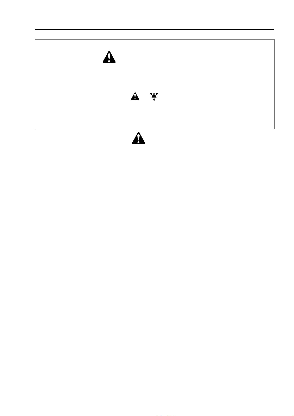
To prevent injury to workers, the symbols and are used to mark safety precautions in this manual.
The cautions accompanyingthese symbolsshould alwaysbe carefullyfollowed. Ifany dangerarises ormay
possibly arise, first consider safety, and take necessary steps to face.
SAFETY
GENERAL PRECAUTIONS
Mistakes in operation extremely dangerous.
Read all the Operation and Maintenance Manual carefully BEFORE operating the machine.
1. Before carrying out anygreasing or repairs,read all
theprecautions writtenon thedecals whichare suck
on the machine.
2. Whencarrying outany operation, alwayswear safety shoes and helmet. Do not wear loose work
clothes, or clothes with buttons missing.
• Always wear safety glasses when hitting parts
with a hammer.
• Always wear safety glasses when grinding
parts with a grinder, etc.
3. If welding repairs are needed, always have a
trained, experienced welder carry out the work.
When carryingout welding work, alwayswear welding gloves, apron, glasses, cap and other clothes
suited for welding work.
4. When carrying out any operation with two or more
workers, always agree on the operating procedure
before starting. Always inform your fellow workers
before starting any step of the operation. Before
starting work, hang UNDER REPAIR signs on the
controls in the operator’s compartment.
5. Keepall toolsin goodcondition andlearn thecorrect
way to use them.
6. Decide a place in the repair workshop to keep tools
and removedparts. Always keep thetools andparts
in their correct places. Always keep the work area
clean andmake surethat thereis nodirt or oilon the
floor.
Smoke onlyin the areasprovided forsmoking. Never smoke while working.
PREPARATIONS FOR WORK
7. Before adding or making any repairs, park the machine onhard, level ground,and blockthe wheels to
prevent the machine from moving.
8. Before starting work, lower outrigger, bucket or any
other work equipment to the ground. If this is not
possible, use blocksto prevent thework equipment
from falling down. In addition, be sure to lock all the
control levers and hang warning sign on them.
9. When disassembling or assembling, support the
machine withblocks, jacks or standsbefore starting
work.
10. Remove allmud andoil fromthe stepsor otherplaces used to get on and off the machine. Always use
thehandrails, laddersor stepswhen gettingon oroff
the machine.
Never jump on or off the machine.
If it is impossible to use the handrails, ladders or
steps, use a stand to provide safe footing.
PRECAUTIONS DURING WORK
11. When removing the oil filler cap, drain plug or hydraulic pressure measuring plugs, loosen them
slowly to prevent the oil from spurting out.
Before disconnecting or removing components of
the hydraulic circuit and engine cooling circuit, first
remove the pressure completely from the circuit.
12. The water and oilin thecircuits are not hot whenthe
engine in stopped, so be careful not to get burned.
Wait for the oil water to cool before carrying out any
work on the cooling water circuits.
13. Before startingwork, removethe leadsfrom the battery. Always remove thelead from the negative (– )
terminal first.
SAFETY
WB91R-2 WB93R-2
00-3
Page 8

SAFETY
14. When raising heavy components, use a hoist or
crane. Check that the wire rope, chains and hooks
are free from damage.
Always use lifting equipment which has ample capacity. Install the lifting equipment at the correct
places.
Use a hoist or crane and operate slowly to prevent
the component from hitting any other part.
Do not work with any part still raised by the hoist or
crane.
15. When removing covers which are under internal
pressure or under pressure from a spring, always
leave twobolts inposition on oppositesides. Slowly
release thepressure, then slowly loosenthe boltsto
remove.
16. When removing components, be careful not to
break or damage the wiring.
Damage wiring may cause electrical fires.
17. When removingpiping, stopthe fuelor oil fromspillingout. Ifany fuelor oildrips onto thefloor, wipeit up
immediately.
Fuel or oil on the floor can cause you to slip, or can
even start fires.
18. As ageneral rule,do notuse gasolineto washparts.
In particular, use only the minimum of gasoline
when washing electrical parts.
19. Be sure to assemble all parts again in their original
places. Replace any damage parts with new parts.
When installing hoses and wires, be sure that they
will not be damaged by contact with other parts
when the machine is being operated.
20. When installing high pressure hoses, make sure
that they are not twisted. Damaged tubes are dangerous, so be extremely careful when installing
tubes for high pressure circuits. Also, check that
connecting parts are correctly tightened.
21. When assembling or installing parts, always use
specified tightening torques.
When installing the parts which vibrate violently or
rotate at high speed, be particulary careful to check
that they are correctly installed.
22. When aligning two holes, never insert your fingers
or hand.
23. When measuring hydraulicpressure, checkthat the
measuring toolis correctlyassembled beforetaking
any measurement.
24. Take sure when removing or installing wheels.
00-4
WB91R-2 WB93R-2
Page 9

FOREWORD
FOREWORD
This shop manual has been prepared as an aid to improve the quality ofrepairs by giving the operator an accurate
understanding of the product and by showing him the correct way to perform repairs and make judgements. Make sure
you understand the contents of this manual and use it to full effect at every opportunity.
This shop manual mainly containsthe necessary technical informationfor operations performed in a service workshop.
The manual is dividedinto chapters on each maingroup of components;these chapters are further divided intothe
following sections.
STRUCTURE AND FUNCTION
This sectionexplains thestructure andfunction of eachcomponent. It serves notonly togive an understanding
of the structure, but also serves as reference material for troubleshooting.
TESTING AND ADJUSTING
This sections explains checks to be made before and after performing repairs, as well as adjustments to be
made at completion of the checks and repairs.
Troubleshooting charts correlating «Problems» to «Causes» are also included in this section.
DISASSEMBLY AND ASSEMBLY
This section explains the order to be followed when removing, installing, disassembling or assembling each
component, as well as precautions to be taken for these operations.
MAINTENANCE STANDARD
This section gives the judgement standards when inspecting disassembled parts.
NOTE
The specifications contained in this shop manual are subject to change at any time and without any notice.
Contact your Komatsu Utility distributor for the latest information.
WB91R-2 WB93R-2
00-5
Page 10
HOW TO READ THE SHOP MANUAL
HOW TO READ THE SHOP MANUAL
VOLUMES
Shop manual are issued as a guide to carry out repairs.
These various volumes are designed to avoid duplicating the same information.
DISTRIBUTION AND UPDATING
Any additions, amendments or other changes will be
sent to Komatsu Utility distributors.
Get themost up-to-dateinformation before you startany
work.
FILING METHOD
1. See the page number on the bottom of the page.
File the pages in correct order.
2. Following examplesshow you howto readthe page
number.
Example:
10
-
3
Item number (10. Structure and
Function)
Consecutive page number for each
item
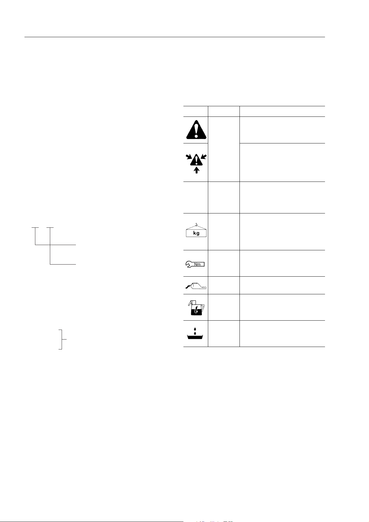
SYMBOLS
In order to make the shop manual greatly chelpful, important points about safety and quality are marked with
the following symbols.
Symbol Item Remarks
Special safety precautions
are necessary when
performing the work.
★
Safety
Caution
Weight
Tightening
torque
Extra special safety precautions
are necessary when performing
the work because it is under internal pressure.
Special technical precautions or
other precautions for preserving
standards are necessary when
performing the work.
Weight of parts or systems.
Caution necessary when selecting hoisting wire, or when working posture is important, etc.
Parts that require special attention for the tightening torque during assembly.
3. Additional pages: additional pagesare indicated by
a hyphen (–) and number after the page number.
Fle as in the example.
Example:
10-4
10-4-1
Added pages
10-4-2
10-5
REVISED EDITION MARK
➀ ➁ ➂ ....)
(
When a manual is revised, an edition mark is recorded
on the bottom outside corner of the pages.
REVISIONS
Revised pages areshown on the LIST OFREVISED PAGES between the title page and SAFETY page.
Coat
Oil, water
Drain
Parts to be coated with adhesives and lubricants etc.
Places where oil, water or fuel
must be added, and their quantity.
Places where oil or water must
be drained, and quantity to be
drained.
00-6
WB91R-2 WB93R-2
Page 11
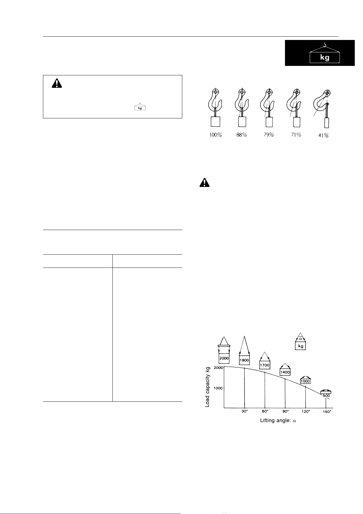
HOISTING INSTRUCTIONS
Heavy parts (25 kg or more) must be lifted
with a hoist etc. In the
section, every part weighing 25 kg or more is
bly
clearly indicated with the symbol
1. If a part cannot be smoothly removed from the machine by hoisting, the following checks should be
made:
• Check for removal of all bolts fastening the part
to the relative parts.
• Check for any part causing interference with
the part to be removed.
2. Wire ropes
1) Use adequate ropes depending on the weightof
parts to be hoisted, referring to the table below:
(Standard «S» or «Z» twist ropes
without galvanizing)
Rope diameter (mm) Allowable load (tons)
10.0
11.2
12.5
14.0
16.0
18.0
Disassembly and Assem-
WIRE ROPES
1.0
1.4
1.6
2.2
2.8
3.6
HOISTING INSTRUCTIONS
Hooks have maximum strength at the middle portion.
3) Do not sling a heavy load with one rope alone, but
sling with two or more ropes symmetrically wound
on to the load.
Slingingwith one rope maycause turningof theload
during hoisting, untwistingof the rope, or slipping of
the rope from its original winding position on the
load, which can cause dangerous accidents.
4) Do not sling a heavy load with ropes forming a wide
hanging angle from the hook.
When hoisting a load with two or more ropes, the
force subjected to each rope will increase with the
hanging angles.
The table below shows the variation of allowable
load (kg) when hoisting is made with two ropes,
each of which is allowed to sling up to 1000 kg vertically, at various handing angles.
When tworopes slinga loadvertically, upto 2000kg
of total weight can be suspended.
This weight becomes 1000 kg when two ropes
make a 120° hanging angle.
On the otherhand,two ropesaresubjected toan excessiveforce aslarge as4000 kgif theysling a2000
kg load at a lifting angle of 150°.
20.0
22.4
30.0
40.0
50.0
60.0
The allowable load value is estimated to be onesixth or one-seventh of the breaking strength of the
rope used.
2) Slingwire ropesfrom themiddle portionof thehook.
Slinging near the edge of the hook may cause the
rope to slip off the hook during hoist
rious accident can result.
4.4
5.6
10.0
18.0
28.0
40.0
ing, and a se-
WB91R-2 WB93R-2
00-7
Page 12
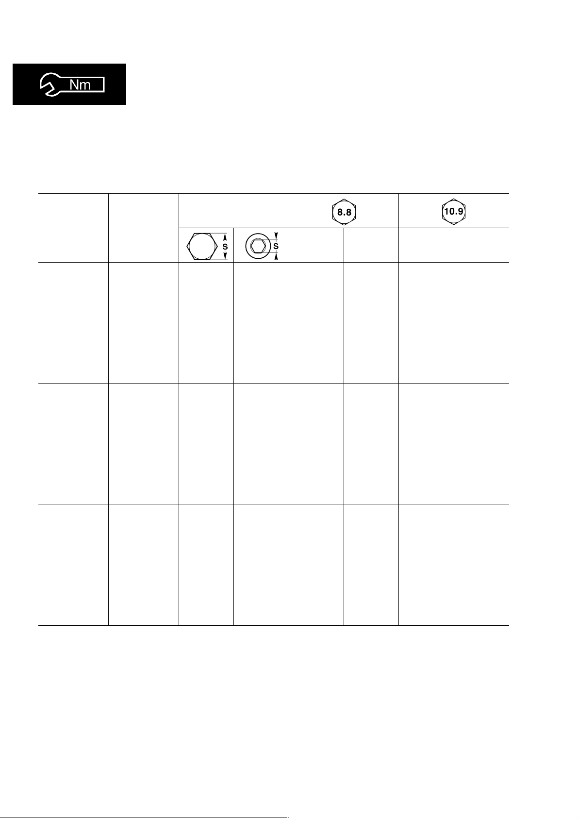
STANDARD TIGHTENING TORQUE
The following charts give the standard tightening torques of bolts and nuts.
Exceptions are given in section of «Disassembly and Assembly».
1. STANDARD TIGHTENING TORQUE OF BOLTS AND NUT
Width across flat
Thread
diameter ofbolts
(mm)
Pitch of
bolts
(mm)
(mm)
kgmNmkgmNm
STANDARD TIGHTENING TORQUE
10
12
14
16
18
20
22
24
27
30
6
8
1
1.25
1.5
1.75
2
2
2.5
2.5
2.5
3
3
3.5
10
13
17
19
22
24
27
30
32
36
41
46
10
12
14
14
17
17
19
19
22
8
6
8
0.96
2.3
4.6
7.8
12.5
19.5
27
38
52
66
96±10
131
±0.1
±0.2
±0.5
±0.8
±1
±2
±3
±4
±6
±7
±14
9.5
23
45
77
122
191
262
372
511
644
945
1287
±1
±2
±4.9
±8
±13
±21
±28
±40
±57
±70
±100
±140
1.3
3.2
6.5
17.5
92
135
184
±0.15
±0.3
±0.6
±1
11
27
±3
±4
37
53
±6
73
±8
±10
±15
±20
±2
13.5
32.2
63
108
172
268
366
524
719
905
1329
1810
±1.5
±3.5
±6.5
±11
±18
±29
±36
±57
±80
±98
±140
±190
33
36
39
This torque table does not apply to bolts or nuts which have to fasten nylon or other parts non-ferrous metal washer.
3.5
4
4
50
55
60
24
27
----
177
230
295
±20
±25
±33
1740
2250
2900
±200
±250
±330
250
320
410
±27
±35
±45
2455
3150
4050
±270
±350
±450
★ Nm (newton meter): 1 Nm = 0.102 kgm
00-8
WB91R-2 WB93R-2
Page 13
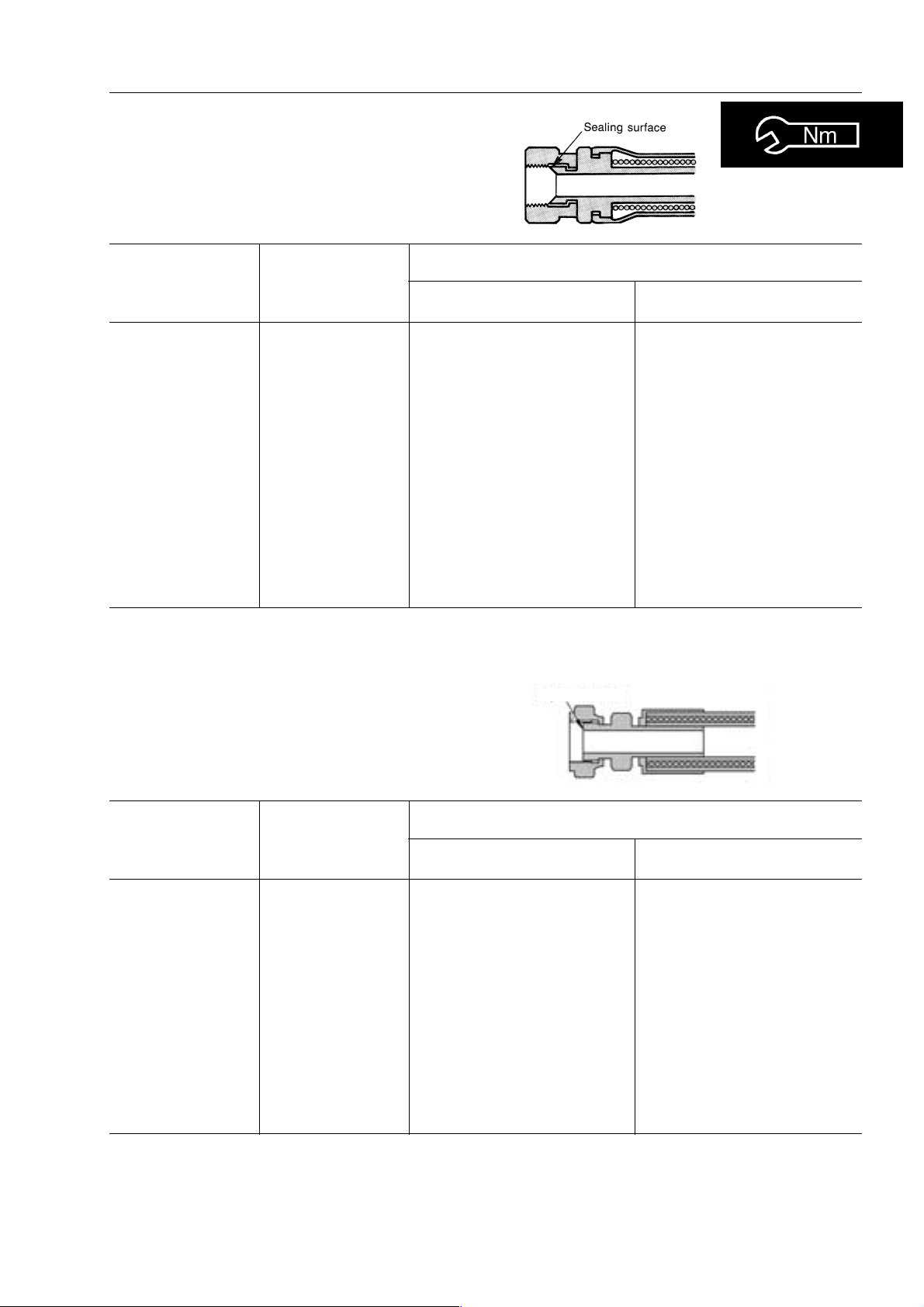
2. TIGHTENING TORQUE FOR NUTS OF FLARED
Use these torques for nut part of flared.
STANDARD TIGHTENING TORQUE
Thread diameter
of nut part
(mm)
1/2” -20
9/16” -18
3/4” -16
7/8” -14
1.1/16 - 12
1.5/16 - 12
1.5/8 - 12
22
33
Width across flats
of nut part
(mm)
17
17
22
27
32
38
50
27
41
TIGHTENING TORQUE
kgm Nm
2.6
4
6.7
9.7
17
20
20
±0.5
±0.5
±2
8
±2
±3
±3
±5
8
±2
±5
Sealing surface
25.5
39.2
65.7
78.5
95.15
166.7
196.2
78.5
196.2
±4.9
±4.9
±19.6
±19.6
±29.4
±29.4
±49
±19.6
±49
Thread diameter
of nut part
(mm)
9/16” -18
11/16” -16
13/16” -16
1” -14
1.3/16 - 12
1.7/16 - 12
1.11/16 - 12
2” -12
WB91R-2 WB93R-2
Width across flats
of nut part
(mm)
17
22
24
30
36
41
50
57
TIGHTENING TORQUE
kgm Nm
2.3–2.5
3.4–3.9
5.2–5.8
8.2–9.2
12.2–13.3
15.3–17.3
18.4–20.4
20.4–24.4
23–25
33–38
51–57
80–90
120–130
150–170
180–200
200–240
00-9
Page 14
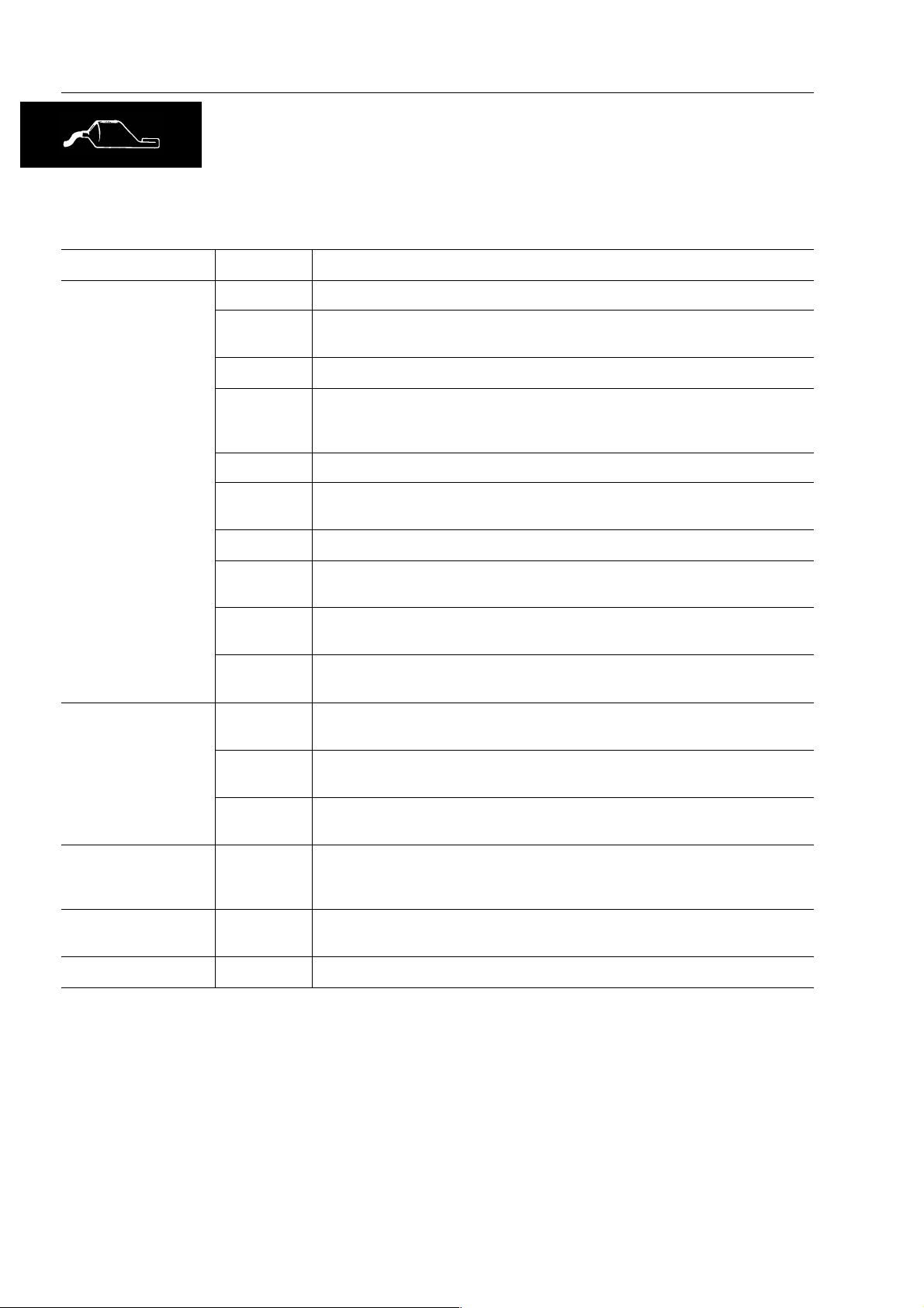
COAT I NG M ATER I A LS
COATIN G MAT ERIAL S
The recommended coating materials prescribed in Komatsu Utility Shop Manuals are listed below:
Nomenclature Code Applications
ASL800010 Used to apply rubber pads, rubber gaskets and cork plugs.
Adhesives
Gasket sealant
ASL800020
Loctite 222 Used for low resistance locking of screws, check nuts and adjustment nuts.
Loctite 242
Loctite 262 Used forhigh resistantof threadedparts thatcan be removed with normal tools.
Loctite 270
Loctite 542 Used for sealing the union threads for hydraulic tubes.
Loctite 573
Loctite 601
Loctite 675
ASL800060
Loctite 510
Used to apply resin,rubber, metallicand non-metallicparts whena fast,strong
seal is needed.
Toprevent theloosening ofbolts, nutsand plugsand the leakageof oil.Used for
medium resistance locking of screws and nuts of every type, and for locking
keys and bearings.
Used for high resistant locking and for sealing threaded parts, bolts and stud
bolts.
Used forsealing ratherexact planesurfaces whenthe optionof possiblefuture
dismantling is required.
Used forhigh resistantlocking ofmechanical componentsthat canbe removed
only after heating
Used to lock cylindrical couplings and for the permanent locking of threaded
parts, and also to lock shafts to bearings, gears, pulleys, pins, bushings, etc.
Used by itself to seal grease fittings, tapered screw fittings and tapered screw
fittings in hydraulic circuits of less than 50 mm in diameter.
Used by itself on mounting flat surface
(Clearance between surfaces within 0.2 mm)
Antifriction compound
(Lubricant including
Molybdenum disulfide)
Grease
(Lithium grease)
Vaseline
00-10
Loctite 518
ASL800040
ASL800050
-----
Used by itself on mounting flat surface
(Clearance between surfaces within 0.5 mm
Applied to bearings and taper shaft to facilitate press-fitting and to prevent
sticking, burning or rusting.
Applied to bearings, sliding parts and oil seals for lubrication, rust prevention
and facilitation of assembling work.
Used for protecting battery electrode terminals from corrosion
WB91R-2 WB93R-2
Page 15
ELECTRIC WIRE CODE
ELECTRIC
In the wiring diagrams various colour and symbols are employed to indicate the thickness of wires.
This wire code table will help you understand WIRING DIAGRAMS.
Example: R–N 1.5 indicates a cable having a nominal number 1.5 and red coating with black stripe.
CLASSIFICATION BY THICKNESS
Nominal
number
0.5 16 0.20 0.35 1.55 3.5
1 14 0.30 0.99 2.80 11
1.5 21 0.30 1.48 3.35 14
2.5 35 0.30 2.47 3.80 20
4 56 0.30 3.95 4.60 28
6 84 0.30 5.93 5.20 37
10 84 0.40 10.55 7.10 53
50 399 0.40 50.11 14 160
Number
strands
Copper wire
Ø of strands
(mm)
Cross section
(mm)
Cable O.D.
(mm)
Current rating
(A)
CLASSIFICATION BY COLOUR AND CODE
Primary Auxiliary
Code A A–BA/BA–G – A–NA/NA–RA/RA–VA/V
Colour Light Blue Light Blue–White Light Blue–Yellow Light Blue–Black Light Blue–Red Light Blue–Green
Code B B–G – B–NB/NB–RB/R – B/V ––
Colour White White–Yellow White–Black White–Red White–Green –
Code C C–BC/BC–L – C–N –––––
Colour Orange Orange–White Orange–Blue Orange–Black ––
Code G G–NG/NG–R – G–V –––––
Colour Yellow Yellow–Black Yellow–Red Yellow–Green ––
Code H H–G – H–L – H–NH/NH–R –––
Colour Grey Grey–Yellow Grey–Blue Grey–Black Grey–Red –
Code L L–BL/BL–G ––L/N ––––
Colour Blue Blue–White Blue–Yellow Blue–Black ––
Code M M–B – M–NM/NM–V –––––
Colour Brown Brown–White Brown–Black Brown–Green ––
Code N ––––––––––
Colour Black –––––
Code R R–G – R–NR/NR–V –––––
Colour Red Red–Yellow Red–Black Red–Green ––
Code S S–G – S–N –––––––
Colour Pink Pink–Yellow Pink–Black –––
Code V V–B – V–NV/N ––––––
Colour Green Green–White Green–Black –––
Code Z Z–BZ/BZ–NZ/N ––––––
Colour Violet Violet–White Violet–Black –––
COMPOSITION OF THE COLOURS
The coloration of two-colour wires is indicated by the composition of the symbol listed.
Example: G–V = Yellow-Green with longitudinal colouring
G/V = Yellow-Green with transversal colouring
WB91R-2 WB93R-2
00-11
Page 16

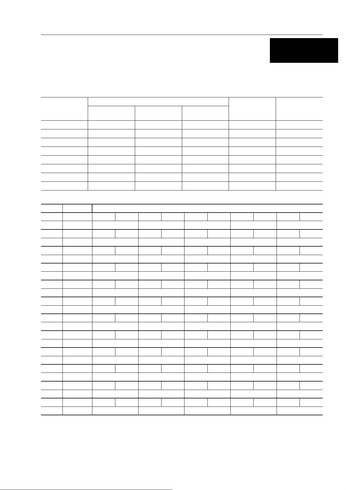
WEIGHT TABLE
WEIGHT TABLE
This weight table is a guide for use when transporting or handling components.
Unit: kg
Machine model WB91R-2 WB93R-2
From serial number 91F20145 93F23453
Engine assembly - Muffler - Exhaust pipe 400 410
Radiator - exchanger 37 37
Hydraulic oil tank (empty) 77 77
Fuel tank (empty) 73 73
Front counterweight 300 300
Engine hood 27 27
Cabin (without seat) 595 595
Seat 34 34
Engine-gear box-pump group 730 740
Piston pump 28 28
Transmission 230 230
Front axle 316 316
Rear axle 511 511
Front wheel
Rear wheel
2-spool control valve
3-spool control valve
Work equipment
• Boom
• Bucket
• Fulcrum lever
• Tilt lever
• Raise cylinder
• Tilt cylinder
Work equipment
• with standard arm
• with long arm
• with jig arm
Boom 323 323
Arm 213 213
Long arm 245 245
Boom swing bracket 133 133
Backframe 237 237
Control valve (6-spool) 47 47
Control valve (7-spool) 53 53
Control valve (8-spool) 59 59
Jig arm 392 392
Outriggers 57 57
Boom cylinder 65 78
Arm cylinder 69 69
Bucket cylinder 49 49
Outriggers cylinder 42 42
Swing cylinder 30 30
Bucket 156 156
65
163
24
30
960
370
427
13x4
48x2
40x2
45x2
850
885
1030
65
163
24
30
960
370
427
13x4
48x2
40x2
45x2
850
885
1030
00-12
WB91R-2 WB93R-2
Page 17
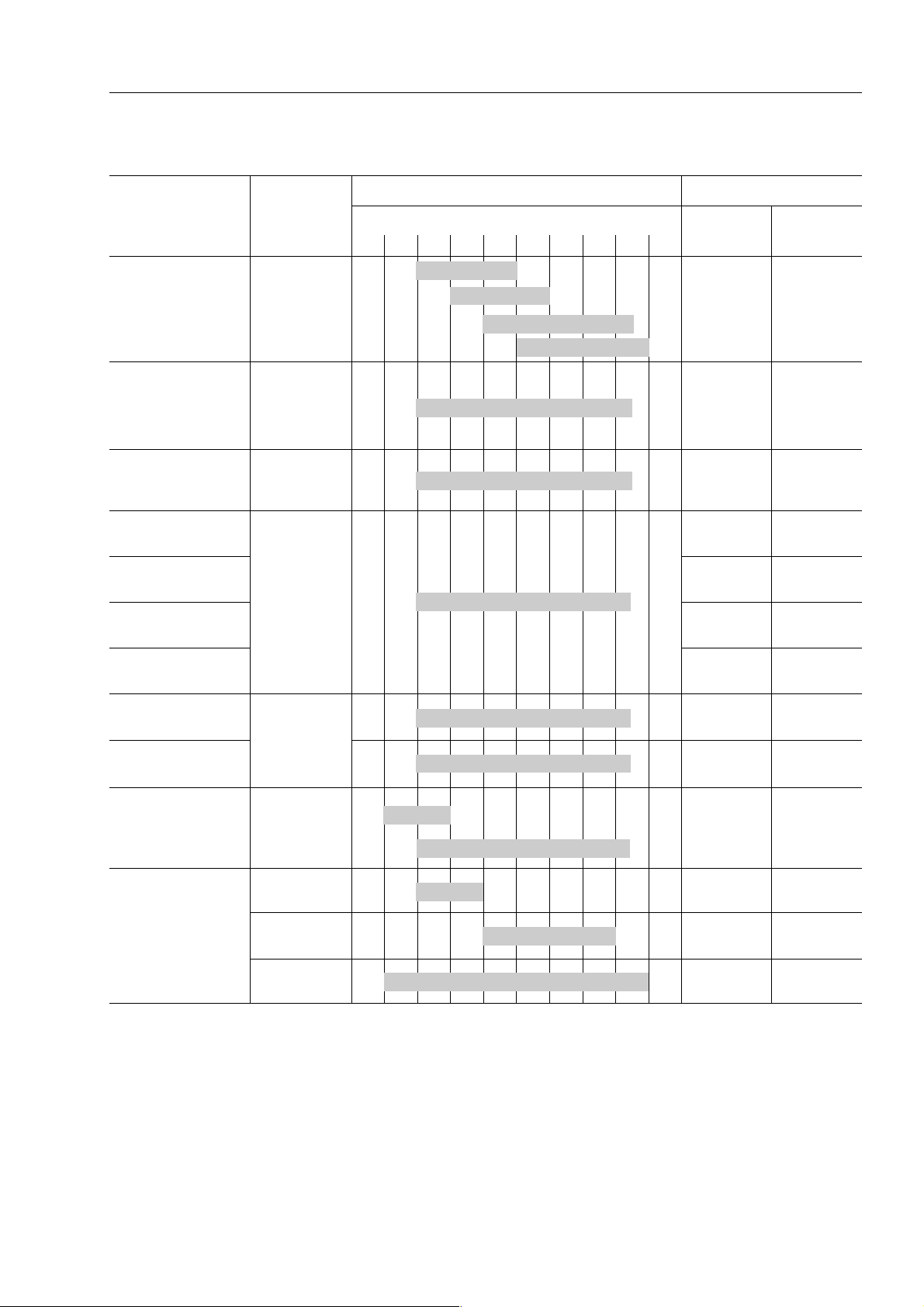
TABLE OF OIL AND COOLANT QUANTITIES
TABLE OF OIL AND COOLANT QUANTITIES
RESERVOIR
Crankcase sump
Hydraulic circuit
Hydraulic circuit
with biodegradable
oil
Front axle
• Differential
• Final reduction gear
(each.)
Rear axle:
• Differential
KIND OF
FLUID
OIL
• API CD
OIL
• API CD
OIL
• UTTO FLUID
AMBIENT TEMPERATURE CAPACITY (
--30--20--
SAE 10W
1001020304050°C
SAE 20W-20
SAE 30
SAE 40
SAE 10W-30
ᐉ)
Specified Refill
7.9 7.9
150 92
150 92
6.5 6.5
11
14.5 14.5
• Final reduction gear
(each.)
Hydraulic
transmission
Braking
system
Fuel tank DIESEL OIL 130 –
Engine coolant
system
OLIO
GM DEXRON® II D
(DEXRON® is a
registered
General Motors
Corporation)
✽
ASTM D975 N.2
WATER +
ANTI-FREEZE
WATER 14 –
PERMANENT
LIQUID
1.5 1.5
20 17
0.8 0.8
14 –
14 –
✽ ASTM D975 N.
ASTM: America Society of Testing and Materials
SAE: Society of Automotive Engineers
API: American Petroleum Institute
MIL: Military Specification
CCMC: Common Market Constructors Committe
First filling quantity:
total quantity of oil, including the oil for the components and pipes.
Oil change quantity:
quantity of oil necessary to fill the system or unit during the normal inspection and maintenance operations.
WB91R-2 WB93R-2
00-13
Page 18

TABLE OF OIL AND COOLANT QUANTITIES
NOTE:
(1) When the diesel oilsulphur content isless then 0.5%, change the engine oilaccording to theperiodic maintenance
intervals indicated in the operationand maintenancemanual. Inthe dieseloil sulphurcontent exceeds0.5% change
the engine oil according to the following table:
Sulphur content Engine oil change interval
from 0.5 to 1.0% 1/2
over 1.0% 1/4
(2) When startingthe engineat temperatures below0 °C, useengine oil SAE10W, 20W-20 and 10W-30,even if during
the day the temperature increases by 10 °C.
(3) Use engineoil with CD classification; ifoil with CD classificationis used, reduce the engineoil change interval by a
half.
(4) Use originalproducts, which havecharacteristics specifically formulatedand approvedfor theengine, the hydraulic
circuit of equipment and for reductions.
of regular interval
of regular interval
00-14
WB91R-2 WB93R-2
Page 19
CONVERSION TABLE
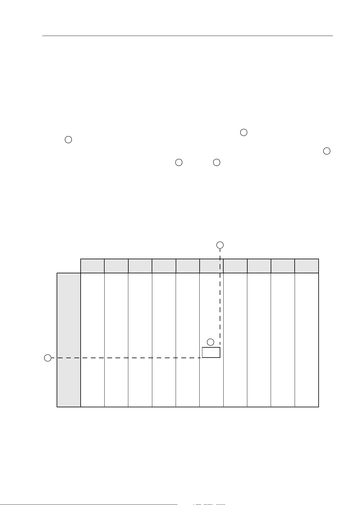
METHOD OF USING THE CONVERSION TABLE
Theconversiontableinthissectionisprovidedtoenablesimpleconversionoffigures.
For details of the method of using the conversion table, see the example given below.
EXAMPLE
• Method of using the conversion table to convert from millimeters to inches.
1. Convert 55 mm into inches.
CONVERSION TABLE
0.236
0.630
1.024
A
, then drow a horizontal line from
1 mm = 0.03937 in.
0.276
0.669
1.063
0.315
0.709
1.102
0.354
0.748
1.142
1 - Locate the number 50 in the vertical column at the left side, take this as
A
.
2 - Locate the number 5 in the row across the top, take this as , then draw a perpendicular line down from .
3 - Take the point where the two lines cross as . This point gives the value when converting from mil-
limeters to inches. Therefore,
2. Convert 550 mm into inches
1 - The number 550 does not appearin the table, so divide by 10 (move the decimal point one place to the left) to
convert it to 55 mm.
2 - Carry out the same procedure as above to convert 55 mm to 2.165 in.
3 - The originalvalue (550 mm) wasdivided by10, somultiply 2.165in. by 10(move the decimalpoint one placeto
the right) to return to the original value. This gives 550 mm = 21.65 in.
From millimeters to inches
0 1 2 3 4 5 6 7 8 9
0.039
0.433
0.827
10
20
0
0
0.394
0.787
55 mm =2.165 in.
0.079
0.472
0.866
0.118
0.512
0.906
C C
0.157
0.551
0.945
0.197
0.591
0.984
B
B
30
40
50
1.181
1.575
1.969
A
60
70
80
90
2.362
2.756
3.150
3.543
WB91R-2 WB93R-2
1.220
1.614
2.008
2.402
2.795
3.189
3.583
1.260
1.654
2.047
2.441
2.835
3.228
3.622
1.299
1.693
2.087
2.480
2.874
3.268
3.661
1.339
1.732
2.126
2.520
2.913
3.307
3.701
1.378
1.772
C
2.165
2.559
2.953
3.346
3.740
1.417
1.811
2.205
2.598
2.992
3.386
3.780
1.457
1.850
2.244
2.638
3.032
3.425
3.819
1.496
1.890
2.283
2.677
3.071
3.465
3.858
1.536
1.929
2.323
2.717
3.110
3.504
3.898
00-15
Page 20
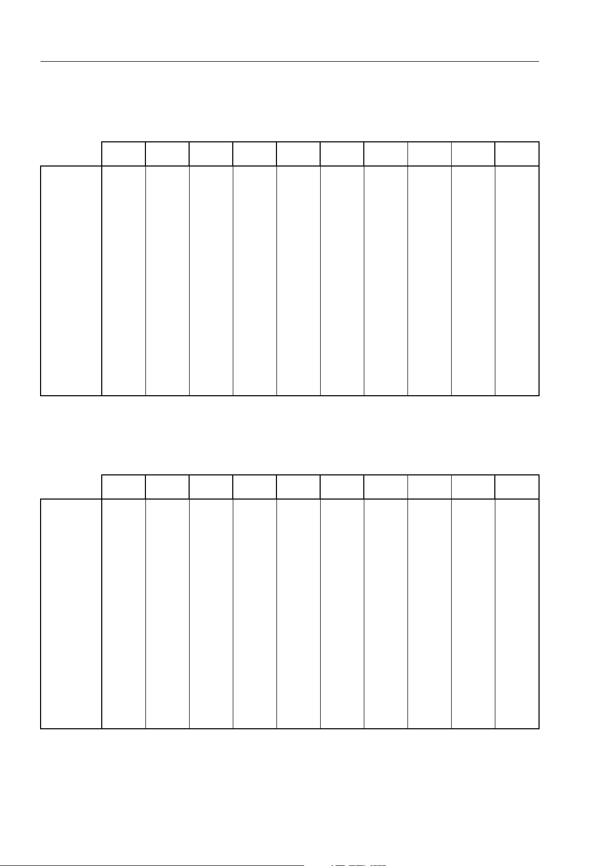
From mm to in.
CONVERSION TABLE
1 mm = 0.03937 in.
0123456789
0
10
20
30
40
50
60
70
80
90
From kg to lb.
0
0.394
0.787
1.181
1.575
1.969
2.362
2.756
3.150
3.543
0.039
0.433
0.827
1.220
1.614
2.008
2.402
2.795
3.189
3.583
0.079
0.472
0.866
1.260
1.654
2.047
2.441
2.835
3.228
3.622
0.118
0.512
0.906
1.299
1.693
2.087
2.480
2.874
3.268
3.661
0.157
0.551
0.945
1.339
1.732
2.126
2.520
2.913
3.307
3.701
0.197
0.591
0.984
1.378
1.772
2.165
2.559
2.953
3.346
3.740
0.236
0.630
1.024
1.417
1.811
2.205
2.598
2.992
3.386
3.780
0.276
0.669
1.063
1.457
1.850
2.244
2.638
3.032
3.425
3.819
0.315
0.709
1.102
1.496
1.890
2.283
2.677
3.071
3.465
3.858
1 kg = 2.2046 lb.
0.354
0.748
1.142
1.536
1.929
2.323
2.717
3.110
3.504
3.898
0
10
20
30
40
50
60
70
80
90
0123456789
0
22.05
44.09
66.14
88.18
110.23
132.28
154.32
176.37
198.42
2.20
24.25
46.30
68.34
90.39
112.44
134.48
156.53
178.57
200.62
4.41
26.46
48.50
70.55
92.59
114.64
136.69
158.73
180.78
202.83
6.61
28.66
50.71
72.75
94.80
116.85
138.89
160.94
182.98
205.03
8.82
30.86
51.91
74.96
97.00
119.05
141.10
163.14
185.19
207.24
11.02
33.07
55.12
77.16
99.21
121.24
143.30
165.35
187.39
209.44
13.23
35.27
57.32
79.37
101.41
123.46
145.51
167.55
189.60
211.64
15.43
37.48
59.53
81.57
103.62
125.66
147.71
169.76
191.80
213.85
17.64
39.68
61.73
83.78
105.82
127.87
149.91
171.96
194.01
216.05
19.84
41.89
63.93
85.98
108.03
130.07
152.12
174.17
196.21
218.26
00-16
WB91R-2 WB93R-2
Page 21
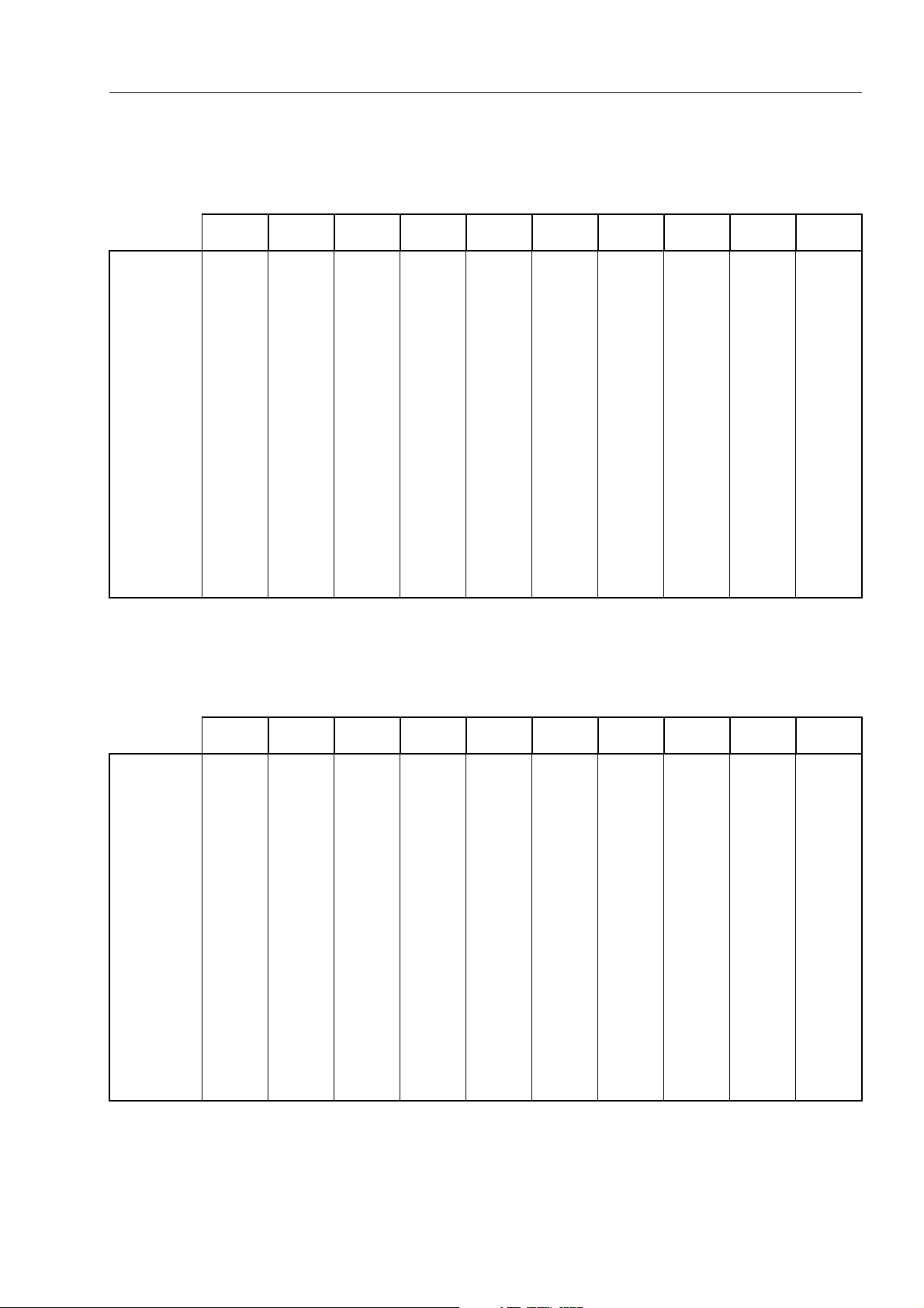
From liter to U.S. Gall.
0123456789
CONVERSION TABLE
1 ᐉ = 0.2642 U.S. Gall.
0
10
20
30
40
50
60
70
80
90
0
2.642
5.283
7.925
10.567
13.209
15.850
18.492
21.134
23.775
From liter to U.K. Gall.
0.264
2.906
5.548
8.189
10.831
13.473
16.115
18.756
21.398
24.040
0.528
3.170
5.812
8.454
11.095
13.737
16.379
19.020
21.662
24.304
0.793
3.434
6.076
8.718
11.359
14.001
16.643
19.285
21.926
24.568
1.057
3.698
6.340
8.982
11.624
14.265
16.907
19.549
22.190
24.832
1.321
3.963
6.604
9.246
11.888
14.529
17.171
19.813
22.455
25.096
1.585
4.227
6.869
9.510
12.152
14.795
17.435
20.077
22.719
25.361
1.849
4.491
7.133
9.774
12.416
15.058
17.700
20.341
22.983
25.625
2.113
4.755
7.397
10.039
12.680
15.322
17.964
20.605
23.247
25.889
1 ᐉ = 0.21997 U.K. Gall.
2.378
5.019
7.661
10.303
12.944
15.586
18.228
20.870
23.511
26.153
0
10
20
30
40
50
60
70
80
90
0123456789
0
2.200
4.399
6.599
8.799
10.998
13.198
15.398
17.598
19.797
0.220
2.420
4.619
6.819
9.019
11.281
13.418
15.618
17.818
20.017
0.440
2.640
4.839
7.039
9.239
11.438
13.638
15.838
18.037
20.237
0.660
2.860
5.059
7.259
9.459
11.658
13.858
16.058
12.257
20.457
0.880
3.080
5.279
7.479
9.679
11.878
14.078
16.278
18.477
20.677
1.100
3.300
5.499
7.969
9.899
12.098
14.298
16.498
18.697
20.897
1.320
3.520
5.719
7.919
10.119
12.318
14.518
16.718
18.917
21.117
1.540
3.740
5.939
8.139
10.339
12.528
14.738
16.938
19.137
21.337
1.760
3.950
6.159
8.359
10.559
12.758
14.958
17.158
19.357
21.557
1.980
4.179
6.379
8.579
10.778
12.978
15.178
17.378
19.577
21.777
WB91R-2 WB93R-2
00-17
Page 22

From Nm to lb.ft.
0123456789
CONVERSION TABLE
1 Nm = 0.737 lb.ft.
0
10
20
30
40
50
60
70
80
90
100
110
120
0
7.370
14.740
22.110
29.480
36.850
44.220
51.590
58.960
66.330
73.700
81.070
88.440
0.737
8.107
15.477
22.847
30.217
37.587
44.957
52.327
59.697
67.067
74.437
81.807
89.177
1.474
8.844
16.214
23.584
30.954
38.324
45.694
53.064
60.434
67.804
75.174
82.544
89.914
2.211
9.581
16.951
24.321
31.691
39.061
46.431
53.801
61.171
68.541
75.911
83.281
90.651
2.948
10.318
17.688
25.058
32.428
39.798
47.168
54.538
61.908
69.278
76.648
84.018
91.388
3.685
11.055
18.425
25.795
33.165
40.535
47.905
55.275
82.645
70.015
77.385
84.755
92.125
4.422
11.792
19.162
26.532
33.902
41.272
48.642
56.012
63.382
70.752
78.122
85.492
92.862
5.159
12.529
19.899
27.269
34.639
42.009
49.379
56.749
64.119
71.489
78.859
86.229
93.599
5.896
13.266
20.636
28.006
35.376
42.746
50.116
57.486
64.856
72.226
79.596
86.966
94.336
6.633
14.003
21.373
28.743
36.113
43.483
50.853
58.223
65.593
72.963
80.333
87.703
95.073
130
140
150
160
170
180
190
95.810
103.180
110.550
117.920
125.290
132.660
140.030
96.547
103.917
111.287
118.657
126.027
133.397
140.767
97.284
104.654
112.024
119.394
126.764
134.134
141.504
98.021
105.391
112.761
120.131
127.501
134.871
142.241
98.758
106.128
113.498
120.868
128.238
135.608
142.978
99.495
106.865
114.235
121.605
128.975
136.345
143.715
100.232
107.602
114.972
122.342
129.712
137.082
144.452
100.969
108.339
115.709
123.079
130.449
137.819
145.189
101.706
109.076
116.446
123.816
131.186
138.556
145.926
102.443
109.813
117.183
124.553
131.923
139.293
146.663
00-18
WB91R-2 WB93R-2
Page 23
From Nm to kgm
0123456789
CONVERSION TABLE
1 Nm = 0.102 kgm
0
10
20
30
40
50
60
70
80
90
100
110
120
0
1.020
2.040
3.060
4.080
5.100
6.120
7.140
8.160
9.180
10.200
11.220
12.240
0.102
1.222
2.142
3.162
4.182
5.202
6.222
7.242
8.262
9.282
10.302
11.322
12.342
0.204
1.224
2.244
3.264
4.284
5.304
6.324
7.344
8.364
9.384
10.404
11.424
12.444
0.306
1.326
2.346
3.366
4.386
5.406
6.426
7.446
8.466
9.486
10.506
11.526
12.546
0.408
1.428
2.448
3.468
4.488
5.508
6.528
7.548
8.568
9.588
10.608
11.628
12.648
0.510
1.530
2.550
3.570
4.590
5.610
6.630
7.650
8.670
9.690
10.710
11.730
12.750
0.612
1.632
2.652
3.672
4.692
5.712
6.732
7.752
8.772
9.792
10.812
11.832
12.852
0.714
1.734
2.754
3.774
4.794
5.814
6.834
7.854
8.874
9.894
10.914
11.934
12.954
0.816
1.836
2.856
3.876
4.896
5.916
6.936
7.956
8.976
9.996
11.016
12.036
13.056
0.918
1.938
2.958
3.978
4.998
6.018
7.038
8.058
9.078
10.098
11.118
12.138
13.158
130
140
150
160
170
180
190
13.260
14.280
15.300
16.320
17.340
18.360
19.380
13.362
14.382
15.402
16.422
17.442
18.462
19.482
13.464
14.484
15.504
16.524
17.544
18.564
19.584
13.566
14.586
15.606
16.626
17.646
18.666
19.686
13.668
14.688
15.708
16.728
17.748
18.768
19.788
13.770
14.790
15.810
16.830
17.850
18.870
19.890
13.872
14.892
15.912
16.932
17.952
18.972
19.992
13.974
14.994
16.014
17.034
18.054
19.074
20.094
14.076
15.096
16.116
17.136
18.156
19.176
20.196
14.178
15.198
16.218
17.238
18.258
19.278
20.298
WB91R-2 WB93R-2
00-19
Page 24
From kgm to lb.ft.
0123456789
CONVERSION TABLE
1 kgm = 7.233 lb.ft.
0
10
20
30
40
50
60
70
80
90
100
110
120
0
72.3
144.7
217.0
289.3
361.7
434.0
506.3
578.6
651.0
723.3
795.6
868.0
7.2
79.6
151.9
224.2
296.6
368.9
441.2
513.5
585.9
658.2
730.5
802.9
875.2
14.5
86.8
159.1
231.5
303.8
376.1
448.5
520.8
593.1
665.4
737.8
810.1
882.4
21.7
94.0
166.4
238.7
311.0
383.4
455.7
528.0
600.3
672.2
745.0
817.3
889.7
28.9
101.3
173.6
245.9
318.3
390.6
462.9
535.2
607.6
679.9
752.2
824.6
896.9
36.2
108.5
180.8
253.2
325.5
397.8
470.2
542.5
614.8
687.1
759.5
831.8
904.1
43.4
115.7
188.1
260.4
332.7
405.1
477.4
549.7
622.0
694.4
766.7
839.0
911.4
50.6
123.0
195.3
267.6
340.0
412.3
484.6
556.9
629.3
701.6
773.9
846.3
918.6
57.9
130.2
202.5
274.9
347.2
419.5
491.8
564.2
636.5
708.8
781.2
853.5
925.8
65.1
137.4
209.8
282.1
354.4
426.8
499.1
571.4
643.7
716.1
788.4
860.7
933.1
130
140
150
160
170
180
190
940.3
1012.6
1084.9
1157.3
1129.6
1301.9
1374.3
947.5
1019.9
1092.2
1164.5
1236.8
1309.2
1381.5
954.8
1027.1
1099.4
1171.7
1244.1
1316.4
1388.7
962.0
1034.3
1106.6
1179.0
1251.3
1323.6
1396.0
969.2
1041.5
1113.9
1186.2
1258.5
1330.9
1403.2
876.5
1048.8
1121.1
1193.4
1265.8
1338.1
1410.4
983.7
1056.0
1128.3
1200.7
1273.0
1345.3
1417.7
990.9
1063.2
1135.6
1207.9
1280.1
1352.6
1424.9
998.2
1070.5
1142.8
1215.1
1287.5
1359.8
1432.1
1005.4
1077.7
1150.0
1222.4
1294.7
1367.0
1439.4
00-20
WB91R-2 WB93R-2
Page 25
From bar to psi (lb/in2)
0123456789
CONVERSION TABLE
1 bar = 14.503 psi
0
10
20
30
40
50
60
70
80
90
100
110
120
0
145.0
290.0
435.1
580.1
725.1
870.2
1015.2
1160.2
1305.3
1450.3
1595.3
1740.4
14.5
159.5
304.6
449.6
594.6
739.6
884.7
1029.7
1174.7
1319.8
1464.8
1609.8
1754.9
29.0
174.0
319.1
464.1
609.1
754.1
899.2
1044.2
1189.2
1334.3
1479.3
1624.3
1769.4
43.5
188.5
333.6
478.6
623.6
768.6
913.7
1058.7
1203.7
1348.8
1493.8
1638.8
1783.9
58.0
203.0
348.1
493.1
638.1
783.2
928.2
1073.2
1218.2
1363.3
1508.3
1653.3
1798.4
72.5
217.5
362.6
507.6
652.6
797.7
942.7
1087.7
1232.7
1377.8
1522.8
1667.8
1812.9
87.0
232.0
377.1
522.1
667.1
812.2
957.2
1102.2
1247.2
1392.3
1537.3
1682.3
1827.4
101.5
246.5
391.6
536.6
681.6
826.7
971.7
1116.7
1261.8
1406.8
1551.8
1696.8
1841.9
116.0
261.0
406.1
551.1
696.1
841.2
986.2
1131.2
1276.3
1421.3
1566.3
1711.3
1856.4
130.5
275.6
420.6
565.6
710.6
855.7
1000.7
1145.7
1290.8
1435.8
1580.8
1725.8
1870.8
130
140
150
160
170
180
190
200
210
220
230
240
1885.4
2030.4
2175.4
2320.5
2465.5
2610.5
2755.6
2900.6
3045.6
3190.7
3335.7
3480.7
1899.9
2044.9
2189.9
2335.0
2480.0
2625.0
2770.0
2915.1
3060.1
3205.2
3350.2
3495.2
1914.4
2059.4
2204.4
2349.5
2494.5
2639.5
2784.6
2929.6
3074.6
3219.7
3364.7
3509.7
1928.9
2073.9
2218.9
2364.0
2509.0
2654.0
2799.1
2944.1
3089.1
3234.2
3379.2
3524.2
1943.4
2088.4
2233.5
2378.5
2523.5
2668.5
2813.6
2958.6
3103.6
3248.7
3393.7
3538.7
1957.9
2102.9
2248.0
2393.0
2538.0
2683.0
2828.1
2973.1
3118.1
3263.2
3408.2
3553.2
1972.4
1217.4
2262.5
2407.5
2552.5
2697.7
2842.6
2987.6
3132.6
3277.7
3422.7
3567.7
1986.9
2131.9
2277.0
2422.0
2567.0
2712.1
2857.1
3002.1
3147.1
3192.2
3437.2
3582.2
2001.4
2146.4
2291.5
2436.5
2581.5
2726.6
2871.6
3016.6
3161.6
3306.7
3451.7
3596.7
2015.9
2160.9
2306.0
2451.0
2596.0
2641.1
2886.1
3031.1
3176.1
3321.2
3466.2
3611.2
WB91R-2 WB93R-2
00-21
Page 26
CONVERSION TABLE
TEMPERATURE
Fahrenheit-Centigrade conversion; a simple way to convert a Fahrenheit temperature reading into a Centigrade temperature reading or vice versa is to enter the accompanying table in the center or boldface column of figures.
These figures refer to the temperature in either Fahrenheit or Centigrade degrees.
If itisdesired to convert fromFahrenheit to Centigrade degrees,consider thecenter columnas atable ofFahrenheit temperatures and read the corresponding Centigrade temperature in the column at the left.
If itis desiredto convert from Centigradeto Fahrenheit degrees,consider thecenter columnas atable ofCentigrade values and read the corresponding Fahrenheit temperature on the right.
1 °C = 33.8°F
°C
–40.4
–37.2
–34.4
–31.7
–28.9
–28.3
–27.8
–27.2
–26.7
–26.1
–25.6
–25.0
–24.4
–23.9
–23.3
–22.8
–22.2
–21.7
–21.1
–20.6
–40
–35
–30
–25
–20
–19
–18
–17
–16
–15
–14
–13
–12
–11
–10
–9
–8
–7
–6
–5
°F °C °F °C °F °C °F
–40.0
–31.0
–22.0
–13.0
–4.0
–2.2
–0.4
1.4
3.2
5.0
6.8
8.6
10.4
12.2
14.0
15.8
17.6
19.4
21.2
23.0
–11.7
–11.1
–10.6
–10.0
–9.4
–8.9
–8.3
–7.8
–7.2
–6.7
–6.1
–5.6
–5.0
–4.4
–3.9
–3.3
–2.8
–2.2
–1.7
–1.1
11
12
13
14
15
16
17
18
19
20
21
22
23
24
25
26
27
28
29
30
51.8
53.6
55.4
57.2
59.0
60.8
62.6
64.4
66.2
68.0
69.8
71.6
73.4
75.2
77.0
78.8
80.6
72.4
84.2
86.0
7.8
8.3
8.9
9.4
10.0
10.6
11.1
11.7
12.2
12.8
13.3
13.9
14.4
15.0
15.6
16.1
16.7
17.2
17.8
18.3
46
47
48
49
50
51
52
53
54
55
56
57
58
59
60
61
62
63
64
65
144.8
116.6
118.4
120.2
122.0
123.8
125.6
127.4
129.2
131.0
132.8
134.6
136.4
138.2
140.0
141.8
143.6
145.4
147.2
149.0
27.2
27.8
28.3
28.9
29.4
30.0
30.6
31.1
31.7
32.2
32.8
33.3
33.9
34.4
35.0
35.6
36.1
36.7
37.2
37.8
81
82
83
84
85
86
87
88
89
90
91
92
93
94
95
96
97
98
99
100
117.8
179.6
181.4
183.2
185.0
186.8
188.6
190.4
192.2
194.0
195.8
197.6
199.4
201.2
203.0
204.8
206.6
208.4
210.2
212.0
–20.0
–19.4
–18.9
–18.3
–17.8
–17.2
–16.7
–16.1
–15.6
–15.0
–14.4
–13.9
–13.3
–12.8
–12.2
00-22
–4
–3
–2
–1
10
24.8
26.6
28.4
30.2
0
32.0
1
33.8
2
35.6
3
37.4
4
39.2
5
41.0
6
42.8
7
44.6
8
46.4
9
48.2
50.0
–0.6
0.0
0.6
1.1
1.7
2.2
2.8
3.3
3.9
4.4
5.0
5.6
6.1
6.7
7.2
31
32
33
34
35
36
37
38
39
40
41
42
43
44
45
87.8
89.6
91.4
93.2
95.0
96.8
98.6
100.4
102.2
104.0
105.8
107.6
109.4
111.2
113.0
18.9
19.4
20.0
20.6
21.1
21.7
22.2
22.8
23.3
23.9
24.4
25.0
25.6
26.1
26.7
66
67
68
69
70
71
72
73
74
75
76
77
78
79
80
150.8
152.6
154.4
156.2
158.0
159.8
161.6
163.4
165.2
167.0
168.8
170.6
172.4
174.2
176.0
40.6
43.3
46.1
48.9
51.7
54.4
57.2
60.0
62.7
65.6
68.3
71.1
73.9
76.7
79.4
105
110
115
120
125
130
135
140
145
150
155
160
165
170
175
221.0
230.0
239.0
248.0
257.0
266.0
275.0
284.0
2930
302.0
311.0
320.0
329.0
338.0
347.0
WB91R-2 WB93R-2
Page 27

GROUP
10
Page 28

40-28
PC15R-8
Page 29

STRUCTURE AND FUNCTION
Power train ................................................................ 2
Transmission (4WD).................................................. 4
Drive shafts................................................................ 9
Control valve block .................................................. 11
Front axle................................................................. 12
Rear axle ................................................................. 15
Hydraulic pump........................................................ 20
Steering unit ............................................................ 41
Hydraulic circuit ....................................................... 43
Shovel control valve ................................................ 44
Backhoe control valve ............................................. 50
CLSS ....................................................................... 57
Solenoid valve ......................................................... 71
Safety valve..............................................................72
Brake pump ..............................................................74
Shovel cylinder .........................................................75
Backhoe cylinder ......................................................76
Air-conditioning unit..................................................80
How the air-conditioning unit functions.....................81
Electrical diagram (1/6) ............................................83
Electrical diagram (2/6) ............................................85
Electrical diagram (3/6) ............................................87
Electrical diagram (4/6) ............................................89
Electrical diagram (5/6) ............................................91
Electrical diagram (6/6) ............................................93
Electrical diagram (Air conditioning).........................95
WB91R-2 WB93R-2
10-1
Page 30

STRUCTURE AND FUNCTION
POWER TRAIN
POWER TRAIN
1
5
2
3
7
4
8
6
RKZ01061
DESCRIPTION
• The driving power for the engine (1) is transmitted
through the flywheel to the converter (2).
The converter (2) uses hydraulic oil to convert the
torque transmitted by the engine (1) into driving
power. The converter (2) transmits motion to the
drive shaft of the transmission (3) and to the drive
shaft of the hydraulic pump (4).
• The transmission (3) has two hydraulically-activated clutches that can be selected by an electricallycontrolled gearselector. It alsohas manual gear selection (four forward gears and four reverse gears).
10-2
• The driving power is transmitted from the transmission flanges (3) to the front (5) and rear (6) axles
through the Cardan drive shafts (7 and 8).
• The driving power transmitted to the front (5) and
rear (6) axles is reducedby thedifferentials andthen
transmitted to the planetary gear through the differential shafts.
WB91R-2 WB93R-2
Page 31

STRUCTURE AND FUNCTION
POWER TRAIN
Gears
1st gear 4.280
2nd gear 2.372 33.939 2.965 50.633
3rd gear 1.236 17.685 1.544 26.367
4th gear 0.662 9.472 0.827 14.123
Transmission Differential Planetary Total Transmission Differential Planetary Total
Front axle Rear axle
61.238 5.350
2.385 6.000
6
Z=37
2.846 6.000
Z=75
91.362
Z=15
4
Z=13
9
8
3
1. Diesel engine
2. Convertor
3. Transmission
4. Hydraulic pump
2
7
1
Z=13
5
5. Front axle
6. Rear axle
7. Front Cardan drive shaft
8. Rear Cardan drive shaft
Z=31 Z=75
9. Rear wheels
10. Front wheels
10
Z=15
RKZ01031
WB91R-2 WB93R-2
10-3
Page 32

STRUCTURE AND FUNCTION
TRANSMISSION (4WD)
Diagram of the power train
TRANSMISSION (4WD)
6
7
Z=27 Z=29
4
5
3
Z=27
Z=29
2
Z=38 Z=28 Z=33
Z=19
Z=24
Z=45
Z=49
Z=36
8
Z=43Z=12
9
1. Engine
2. Convertor
3. Forward clutch
4. Transmission
5. Reverse clutch
10-4
1
RKZ01040
6. Hydraulic pump
7. Rear flange
8. 4WD engagement device
9. Front flange
WB91R-2 WB93R-2
Page 33

STRUCTURE AND FUNCTION
Hydraulic convertor-transmission circuit diagram
TRANSMISSION (4WD)
0.5-3.5 bar with
reverse/forward gear engaged
0.5-5 bar in neutral
4
2
Ø2
Bearing
gear
Ø3
nd
2
Ø4
gear
st
1
gear
Ø4
rd
4
5
Forward
Ø5-Ø7
t°
11-13 bar
Ø 0.75
Hose Hose
Ø3.5
Ø1.3
Ø3.5
Ø4.5
Reverse
11-13 bar
gear
Ø3
th
3
6
Ø2
Bearing
11-13 bar
Air breather
7
Opening 23 bar
3
Valve open
3.45 bar
3
15
Opening
3.5-5.5 bar
0.5-9.0 bar
1
1. Convertor pressurization valve
2. Convertor
3. Engine
4. Oil cooler
5. Forward clutch
6. Reverse clutch
7. Max. pressure valve: calib. 23 bar
8. Spin-on filter (15
mm)
13
12
8
11
13-15.5 bar - 2200 rpm
13-14 bar - 900 rpm
14
9. Pump
10. Suction filter (250
11. 4WD engagement device
12. Check valve
13. Pressure control
14. 4WD engagement solenoid
15. Control valve group
mm)
9
4WD
10
Transmission oil sump
RKZ04921
WB91R-2 WB93R-2
10-5
Page 34

STRUCTURE AND FUNCTION
TRANSMISSION
TRANSMISSION
b 2
c
E
1
FF
d
3
a
A
4
E
D
D
A
5
7
B
6
B
8
a. From the oil cooler
b. To the oil cooler
c. To the solenoid valve group ST1 (Port P)
d. From the solenoid valve group ST1 (Port T)
RKZ00972
1. Gear lever
2. Convertor
3. Filter
4. Oil temperature sensor
5. Suction filter
6. Y5 Reverse gears command solenoid
7. Y4 Forward gears command solenoid
8. Y2 4WD command solenoid
10-6
WB91R-2 WB93R-2
Page 35

STRUCTURE AND FUNCTION
TRANSMISSION
34
1
2
5
6
17
16
15
1. Hydraulic pump drive shaft
2. Propeller shaft
3. Reverse gears command clutch
4. Forward gears command clutch
5. Reverse gears idler shaft
6. Drive shaft
7. Flange
8. 3rd gear driven gear
9. 4th gear driven gear
14
13
Section A - A
Sezione A - A
10. 4WD drive gear
11. 1st gear driven gear
12. 4WD driven gear
13. 4WD engagement device
14. Front output shaft
15. Flange
16. 2nd gear driven gear
17. Rear output shaft
12
11
10
9
8
7
RKZ04910
WB91R-2 WB93R-2
10-7
Page 36

STRUCTURE AND FUNCTION
C
1
2
9
C
TRANSMISSION
10
4
3
5
6
78
9
10
Section D - D
Sezione D - D
1. Gear-shift piston
2. Spring
3. Spring
4. Ball
5. 3rd and 4th gear selecting fork
6. 1st and 2nd gear selector piston
7. 3rd and 4th gear selector piston
8. 1st and 2nd gear selecting fork
9. 4th gear selecting sensor
12
Section B - B
Sezione B - B
13
10. 3rd and 4th gear selecting fork
11. 1st and 2nd gear selecting fork
12. Suction filter (250
13. Spin-on filter (15
14. Valve
15. Spring
16. Ball
17. Spring
11
15
14
Section E - E
Sezione E - E
mm)
mm)
Section C - C
Sezione C - C
17
16
RKZ00991
10-8
WB91R-2 WB93R-2
Page 37

STRUCTURE AND FUNCTION
DRIVE SHAFTS
Drive shaft for forward and reverse movement
1
6
5
DRIVE SHAFTS
2
bc
a
a. Port commanding reverse clutch
b. Port commanding forward clutch
c. Lubrication port
Driven gear shaft
1
4
1. Reverse gear clutch (Z=29)
2. Forward gear clutch (Z=29)
3. Forwardclutchpiston
4. Reverseclutchpiston
5. Thrust ring
6. Driven shaft
2
3
4
3
5
RKZ00950
6
8
1. Driven gear for 2st gear (Z=43)
2. Driven gear for 1st gear (Z=49)
3. 4WD drive gear (Z=45)
4. Driven gear for 4th gear (Z=24)
WB91R-2 WB93R-2
8
5. Driven gear for 3rd gear (Z=33)
6. Rear output shaft
7. Thrust ring
8. Synchronizer
7
RKZ01010
10-9
Page 38

STRUCTURE AND FUNCTION
4WD driven shaft
DRIVE SHAFTS
1
a. 4WD disengagement command port 1. Front output shaft
a
6
5
4
2. 4WD driven gear (Z=36)
3. Thrust ring
4. Cylinder
5. Spring
6. Disc
2
3
RKZ01021
10-10
WB91R-2 WB93R-2
Page 39

STRUCTURE AND FUNCTION
CONTROL VALVE BLOCK
CONTROL VALVE BLOCK
15
2
1
34
14
Section F - F
Sezione F - F
5
67 8
9
10
11
12
13
12
RKZ01000
1. Ball
2. Spring
3. Piston
4. Spring
5. Spring
6. Spring-guide pin
7. Valve
8. Spring
WB91R-2 WB93R-2
9. Valve
10. Rod
11. Spring
12. Spool return spring
13. Spool
14. Forward gear command solenoid
15. Reverse gear command solenoid
10-11
Page 40

STRUCTURE AND FUNCTION
FRONT AXLE
Differential
FRONT AXLE
3
2
1
1
4
5
17
1. Planetary gear
2. Ring bevel gear (Z=31)
3. Bevel gear
4. Lock nut
5. Half-axle
6. Pin
7. Differential housing
8. Spacer
9. Bearing
7
16
7
15
8
14
9
13
10
12
6
11
10. Seal
11. Flange
12. Cover
13. Lock nut
14. Bearing
15. Bevel pinion (Z=13)
16. Pin
17. Oil drain plug
RKZ00581
10-12
WB91R-2 WB93R-2
Page 41

STRUCTURE AND FUNCTION
Final reduction - joint
3
2
4
1
24
FRONT AXLE
7
5
8
9
6
10
11
23
22
21
1. Planetary carrier
2. Planetary (Z =29)
3. Ring gear (Z=75)
4. Ring gear carrier
5. Wheel hub
6. Seal
7. Pin
8. Shim
9. Protection
10. Bushing
11. Seal
12. Axle body
20
19
18
17
16
13
14
15
13. Bearing
14. Joint
15. Pin
16. Protection
17. Seal
18. Bearing
19. Snap ring
20. Steady pin
21. Stud bolt
22. Plug
23. Sun gear (Z=15)
24. Snap ring
12
RKZ00611
WB91R-2 WB93R-2
10-13
Page 42

STRUCTURE AND FUNCTION
Steering cylinder
FRONT AXLE
A
C
A
B
1
B
2
3
ab
Section A - A
Sezione A - A
1. Steering cylinder
2. Oil refilling plug
3. Oil drain plug
4. Nut
5. Adjustment screw
6. Nut
7. Bushing
7
7
5
4
Section B - B
Sezione B - B
6
Detail C
Particolare C
RKZ00591
a Port - From the steering unit (L Port)
b Port - From the steering unit (R Port)
10-14
WB91R-2 WB93R-2
Page 43

STRUCTURE AND FUNCTION
REAR AXLE
Differential
REAR AXLE
15
12
14
7
13
3456
8
9
7
10
1. Bearing
2. Planetary gear
3. Bevel gear
4. Ring bevel gear (Z=37)
5. Differential housing
6. Lock nut
7. Half-axle
8. Pin
WB91R-2 WB93R-2
12
11
RKZ04970
9. Bearing
10. Nut
11. Seal
12. Flange
13. Spacer
14. Bevel pinion (Z=13)
15. Differential housing
10-15
Page 44

STRUCTURE AND FUNCTION
Final reduction
REAR AXLE
16
10
15
14
4
2
3
5
6
7
8
1
9
11
1. Planetary gear carrier
2. Stud bolt
3. Wheel hub
4. Planetary gears (Z=28)
5. Ring bevel gear carrier
6. Bearing
7. Seal
8. Joint
9. Half-axle
10-16
13
12
RKZ04980
10. Planetary gear (Z=15)
11. Bushing
12. Snap ring
13. Ring gear (Z=75)
14. Oil plug
15. Steady pin
16. Pin
WB91R-2 WB93R-2
Page 45

STRUCTURE AND FUNCTION
Brakes
B
REAR AXLE
A
1
A
9
7
8
3
4
10
2
6
5
1
Detail B
Particolare B
Section A - A
Sezione A - A
RKZ04990
1. Bushing
2. Parking brake control rod
3. Bleeder valve
4. Parking brake lever
5. Parking brake control cam
WB91R-2 WB93R-2
6. Brake disk
7. Piston
8. Spring
9. Pressure disk
10. Intermediate disk
10-17
Page 46

STRUCTURE AND FUNCTION
Differential locking
REAR AXLE
1
2
8
a
7
6
a. From the solenoid valve block ST1 (Port 2)
1. Sleeve
2. Pin
3. Control rod
4. Spacer
5. Fork
6. Piston
7. Cover
8. Snap ring
10-18
5
3
4
RKZ05000
WB91R-2 WB93R-2
Page 47

PAGE INTENTIONALLY
LEFT BLANK
Page 48

STRUCTURE AND FUNCTION
HYDRAULIC PUMP
1
HYDRAULIC PUMP
A
3
D
c
BB
D
A
ba
2
d
1. Delivery variation group
2. Y1 solenoid valve working mode
3. Delivery control valve
10-20
RKZ04930
a. Port L1 - To the intake flange (Spool Port)
b. Port B - To the shovel control valve (Port P)
c. Port X2 - From the shovel control valve
(Port LS)
d. Port L - To the hydraulic oil tank
e. Port S - To the hydraulic oil tank
WB91R-2 WB93R-2
Page 49

STRUCTURE AND FUNCTION
HYDRAULIC PUMP
CC
3
4
2
1
5
Section A - A
Sezione A - A
1. Seal
2. Bearing
3. Central spring
4. Bearing
5. Control rod
6. Swash plate
7
8
9
6
11
12
Section B - B
Sezione B - B
10. Positioning piston
11. Piston
12. Guide shoe
10
7. Positioning piston
8. Spring
9. Cylinder block
RKZ00380
WB91R-2 WB93R-2
10-21
Page 50

STRUCTURE AND FUNCTION
HYDRAULIC PUMP
1
2
Section C - C
Sezione C - C
3
8
4
9
7
10
5
6
15
POWER GOVERNOR
1. Spring
2. Piston rod
3. Bushing
4. Initial adjustment spring
5. Pressure cut calibration spring
6. Pressure cut calibration screw
7. Initial adjustment calibration screw
PC VALVE
8. Spool
9. Spring (internal)
10. Spring (external)
10-22
14
Section D - D
Sezione D - D
13
12
LS VALVE
11. External spring
12. Internal spring
13. Throttles
14. Throttles
15. Spool
11
RKZ00642
WB91R-2 WB93R-2
Page 51

STRUCTURE AND FUNCTION
FUNCTION
• The rotation and torque transmitted to the pump
shaft is converted into hydraulic energy and pressurized oil is deliveredaccording tothe loadrequirements.
• The amount of oil delivered can be modified by
changing the angle of the swash plate.
HYDRAULIC PUMP
1
2
B
3
A
4
5
6
a
7
RKZ01120
STRUCTURE
• The cylinder block (6) is supported and connected
to the shaft (1) by the spline a and the shaft (1) is
supported by the front and rear bearings.
• The tip of the piston (6) is ball-shaped. The shoe (4)
is caulked to itto form oneunit in sucha waythat the
piston (5) and theshoe (4) togetherform a spherical
bearing.
• The swash plate (3) has a flat surface A and the
shoe (4) remainspressed against this surface while
sliding in a circular movement.
The swash plate brings highly pressurized oil onto
the cylindrical surface B fashionedin thepump body
(2), whichmeans thatthe swash plate (3) slides ona
hydrostatically-supported bearing.
WB91R-2 WB93R-2
• The pistons (5) perform their relative movements in
an axial direction, inside cylindrical chambers fashioned in the cylinder block (6).
• The oil is brought up to pressure in the chambers of
the cylinder block (6) by the rotatory movement of
the block itself. The areas of pressure and suction
are determined by the swash plate (7).
Thesurfaceoftheswashplateissodesignedthat
the oil pressure always remains within acceptable
limits.
The oil in each chamber is drawn in and discharged
through holes in the valve plate (7).
10-23
Page 52

STRUCTURE AND FUNCTION
OPERATION
1. Pump operation
1 - The cylinder block (7) rotates together with the
shaft (1) and the shoe (4) slides on the flat surface A. The swash plate (3) moves along the
cylindrical surface B. The angle
tween the center line of the shaft (1) and the
center line X of the swash plate (3) changes,
thus modifying the axial position of the pistons
in relation to the cylinder block.
The angle
= is known as theswash plateangle.
= formed be-
HYDRAULIC PUMP
4
1
3
A
5
6
D
2 - When the center line X of the swash plate (3)
maintains the angle
line of the shaft (1), and hence also of the cylinder block (6),the flatsurface Aacts as a cam for
the shoe(4). Asthe piston(5) rotatesand slides
inside thecylinder block (6), it therefore creates
a difference between the volumes C and D
which provokes intake and discharge of the oil
in quantities equal to the difference between
the volumes (D – C=delivery).
In otherwords, as the cylinderblock (6) rotates,
chamber D loses volume while the volume of
chamber C is increased, thus provoking an intake of oil.
(The figure indicates the state of the pump
when the intake of chamber D and the delivery
of chamber C have been completed).
3 - When the center line X of the swash plate (3)
and the center line of the cylinder block (6) are
perfectly aligned (the swash plate angle
the difference between the volumes C and D
within the cylinder block (6) becomes 0 and the
pump does not take in or deliver any oil. (In
practice the swash plate angle
comes=0)
= in relation to the center
==0),
= never be-
X
X
=0
B
C
RKZ01100
3
6
D
4 - In other words, pump delivery is directly pro-
portional to the swash plate angle
=.
10-24
C
RKZ01110
WB91R-2 WB93R-2
Page 53

STRUCTURE AND FUNCTION
2. Control of Delivery
HYDRAULIC PUMP
1 - As the swash plate angle = grows larger, the
difference between volumes C and D increases, and the delivery Q also increases.
The swash plate angle is modified by servo-pistons (8) and (9).
2 - The servo-piston (8) moves in a reciprocating
linear motion ( ) caused by pressure signals from the PC and LS valves.
The linear movement is transmitted to the
swash plate (3), which is supported by the cylindrical surface of the cradle (2). The swash
plate therefore has a semi-circular reciprocating movement ( ).
3 - The surfaces of the servo-pistons receiving the
pressures PP and LS are dissimilar. The delivery pressure PP of the main pump is always
passed into the smaller (upper) pressure
chamber, whereas the pressure PEN coming
from theLS valve is passedinto the larger (lower) pressure chamber.
The movement of the servo-piston is governed
by the relationship between pressures PP and
PEN, as well by the proportions between the
surfaces (larger and smaller) of the servo-piston.
2
3
9
D
8
C
RKZ01130
WB91R-2 WB93R-2
10-25
Page 54

STRUCTURE AND FUNCTION
PC VALVE, LS VALVE, SERVO PISTON
HYDRAULIC PUMP
1
2
Control valve
3
SERVO-PISTON
1. Spring
2. Servo-piston
3. Servo-piston
LS VALVE
4. Piston
5. Spring
To the actuator
5
4
7
PC VALVE
6. Servo-piston
7. Spring
6
RKZ01141
10-26
WB91R-2 WB93R-2
Page 55

STRUCTURE AND FUNCTION
LS VALVE
FUNCTION
• The LS valve controls the pump delivery according
to the stroke of the control valve level, i.e., in function of the delivery demands madeby the actuators.
• The LS valve detects the actuator’s delivery needs
by means of thedifferential pressure
between the pump delivery pressure PP and the
pressure PLS coming from the control valve. This
reading permits control of the main pump delivery
Q.
(PP, PLS and
pressure, the Load Sensing pressure, and the difference in pressure between these two values).
• In other words, the LS valve detects the pressure
difference
oil flow through the surface freed by the control
valve spool, and controls the pump delivery Q so as
to keep the pressure drop constant.
It can therefore be assumed that the pump delivery
is proportional to the demands made known by the
control valve.
,PLS are, respectively, the pump
,PLS generated by the passage of the
,PLS existing
HYDRAULIC PUMP
WB91R-2 WB93R-2
10-27
Page 56

STRUCTURE AND FUNCTION
OPERATION
1. When the control valve is in a «NEUTRAL» position
4
b
PP
c
d
T
HYDRAULIC PUMP
P
LS
a
6
To the actuator
Min
PP
Max
M
2
• The pressure PLS of the LScoming from the control
valve outlet passes into chamber a ofthespringof
the LS valve. The pressure PP of the pump passes
into chamber b of the opposite side.
• The piston rod movement (4) is determined by the
combination of the force generated by the pressure
PLS, the force of the spring (6) and the force generated on the side opposite the piston rod by the
pressure PP.
• Before the engine is started the servo-piston (3) is
pushed to the right by the spring (1) (corresponding
to the maximum angle of the swash plate).
• If all the control valve spools are in their «NEUTRAL» position when the engine is started, the
pressure PLS of the LS will remain at 6
cause no oil is flowing through the control valve.
AtthesametimethepumppressurePP increases
and is maintained at a value of about 27 bar.
±2barbe-
Control valve
3
X
1
Y
• For this reason the piston (4) is thrust to the right
( ) and a passage is formed between the delivery
lines c and d. This opening enables the pump pressure PP to enter chamber X of the servo-piston (3).
• Although the pump pressure PP is always passed
into chamber Y of the servo-piston (2), since the
force exertedby that pressure onpiston (3) exceeds
the force exerted on piston (2), the servo-piston (1)
moves to the right ( ), i.e. towards the side of the
minimum angle of the swash plate.
RKZ01151
10-28
WB91R-2 WB93R-2
Page 57

STRUCTURE AND FUNCTION
2. When a control valve lever is activated
4
b
PP
c
d
HYDRAULIC PUMP
LS
T
e
P
a
6
To the actuator
Min
PP
Max
M
2
• When the control valve lever is moved out of its
NEUTRAL position, the opening f is determined, allowing an LS signal to be generated.
• Until the
exerted by the spring (6) on the spool (4),the system
will remain stable.
When the opening f is such as to provoke a reduction in
form a passage between delivery lines d and e.The
chamber X loses pressure and the servo-piston
causes the swash plate to move towards maximum
displacement.
,PLS generates a force less thanthe force
,PLS, the spool (4)moves to the left( ) to
Control valve
3
X
f
1
Y
• Equilibrium is re-established in the system when the
pressure
ference in force exerted by the spring (6), and the
passage between delivery lines c and d is reopened.
,PLS generates on the spool (4) the dif-
RKZ01161
WB91R-2 WB93R-2
10-29
Page 58

STRUCTURE AND FUNCTION
3. When the control valve opening is at its maximum (lever at the end of its stroke)
4
b
LS
PP
c
d
T
e
P
a
6
HYDRAULIC PUMP
Min
PP
Max
M
2
• When thecontrol lever is moved tofull stroke, in other words, when the spool opening reaches its maximum, the difference between the pump pressure
PP and the LS pressure PLS becomes smaller (differential pressure
• The LSpressure PLSintroduced intothe chamber a
of the LS valve becomes about the same as the
pump pressurePP andthe piston(4) ismoved to the
left ( ) by the combined forces generated by the
pressure PLS and the spring (6).
The piston movement closes the delivery line c and
forms a passage between lines d and e.
,PLS).
To the actuator
Control valve
3
X
f
1
Y
• The pressurized oil present in the chamber X of the
servo-cylinder (3) flows through the lines d and e
and reaches the pump drainage chamber, so that
the pressure in chamber X of the servo-cylinder (1)
becomes equal to the drainage pressure.
• The servo-piston(3) is thus moved to the right ( )
by swash plate movement due tothe pressure PPin
the chamber Y of the servo-cylinder (2).
In other words, it is drawn in the direction of the increase in angle of the swash plate.
RKZ01161
10-30
WB91R-2 WB93R-2
Page 59

STRUCTURE AND FUNCTION
4. When the spool makes very small movements (fine-control)
4
b
LS
PP
c
d
T
e
P
a
To the actuator
HYDRAULIC PUMP
6
Min
PP
Max
M
2
• When the control valve lever moves in very small increments towards the «NEUTRAL» position, i.e.
when thecontrol valve opening f diminishes, the differential pressure
sure PP and the LS pressure PLS increases.
• If the differential pressure
spool (4) a differencein forcethat exceeds theforce
exerted by the spring (6), the spool moves to the
right ( ) and a passage is formed between the
delivery lines c and d. The pressure PP is introduced into the chamber X and the swash plate
moves towards its minimum angle.
• When the control valve lever performs small movements towards the position of maximum opening,
i.e. when the opening f of the control valve increases, the differential pressure
,PLS between the pump pres-
,PLS generates on the
,PLS diminishes.
Control valve
3
X
f
1
Y
• If the differential pressure
spool (4) a force differencethat does not exceedthe
force exerted by the spring (6), the spool (4) moves
to the left ( ) and a passage is formed between
the delivery lines d and e.
The chamberX losespressure and theservo-piston
provokes a movement of the swash plate towards
maximum displacement.
• Equilibrium is re-established in the system when the
pressure
ference inforce exerted by the spring (6),and hence
the passage between delivery lines c and d is also
re-opened.
,PLS generates on the spool (4) the dif-
RKZ01171
,PLS generates on the
WB91R-2 WB93R-2
10-31
Page 60

STRUCTURE AND FUNCTION
5. When pump flow matches the demands of the control valve
4
b
LS
PP
T
P
c
g
d
e
a
To the actuator
HYDRAULIC PUMP
6
Hold
PP
M
PP
2
• Let A1 be the surface of the servo-piston (3), A2 the
surface of the servo-piston (2), PEN the pressure
acting on the piston (1) and PP the pressure acting
onthepistonside(2).
When pump delivery reaches the quantity demanded by the control valve, the pump pressure PP in
chamber b of the LS valve is in equilibrium with the
combined forces of the LS pressure PLS in chamber a, and the force exerted by the spring (6).
Once equilibrium has been reached the piston (4)
stops in the central position.
• In this condition the passage from chamber c to
chamber d remains only slightly open in order to
maintain pressure in chamber d.
Control valve
PEN
A1
3
X
1
A2
Y
A flow of oil is introduced into the servo-cylinder (3)
at a pressure that balances the force generated by
the pump pressure PP in the cylinder (2).
(PEN x A1=PP x A2).
• The stability of the equilibrium is guaranteed by a
flow stabilized by the throttle g.
• The force of the spring (6) is regulatedso that the piston (4) is in equilibrium when
PP – PLS =
• In practice, the pump flow is made proportional to
the sectionof the opening of the controlvalve, which
maintains the differential pressure
,PLS =18 bar.
RKZ01181
,PLS = 18 bar.
10-32
WB91R-2 WB93R-2
Page 61

STRUCTURE AND FUNCTION
PC VALVE
FUNCTION
• The PC valve performs an approximate power
check, and ensures that the hydraulic horse-power
absorbed bythe pump does not exceed the horsepower delivered by the endothermal engine.
This is achieved by limiting the pump delivery Q in
function of the delivery pressure PP,eveniftheLS
valve requests an increase in delivery Q due to the
larger sectionfreed by the controlvalve spool, in the
presence of high pressure pump delivery.
• In other words, when during operation the delivery
Q increases and the delivery pressure PP also in-
creases simultaneously, the PC valve reduces the
pump delivery Q. When the delivery pressure PP
decreases, the PC valve increases the pump flow.
• The relationships between the pump delivery pres-
sure PP and the delivery Q are shown in the diagram.
HYDRAULIC PUMP
Pump discharge amount Q
Pump discharge pressure
PP
RKP01181
WB91R-2 WB93R-2
10-33
Page 62

STRUCTURE AND FUNCTION
OPERATION
1. When the load on the actuators is heavy (high pump delivery pressure)
f
5
∆ p
PPC
HYDRAULIC PUMP
g
6
7
c
e
d
3
2
ab
1
4
PPC
PP
PP
Min
P
EN
T
Control valve
Max
LS
To the actuator
M
• When a higher delivery is required, the LS valve re-
ceives a signal from the control valve to bring the
pump up to maximum displacement.
When the swash plate moves it also moves the
bushing (2) joined to it (by the pin (1)), which releases the spring (3).
• As the pressure of the actuators increases, pres-
sure also increases in the delivery line c. When the
calibrated setting of thespring (3) is reached, thepiston rod (4) is thrust to the left ( ) and the passage between chamber b and the pump drainage
chamber a is opened.
X
8
RKZ01191
• The opening of the passagebetween the chambers
b and a generates a flowof oil and hence, dueto the
calibrated hole (6), a
chambers f andg atthe sidesopposite the spool(5).
(
,P=PP– PPC)
• When the value of PP exceeds the value of the
spring loading (7) the spool (5) moves to the right
( ) opening the passage between the delivery
lines d and e and sending the pumppressure PPtowards the servo-cylinder (8).
• The pressure PP introduced into chamber X of the
cylinder (8) pushes it towards the minimum angle of
theswashplate( ).
,P is generated between
10-34
WB91R-2 WB93R-2
Page 63

STRUCTURE AND FUNCTION
2. When equilibrium has been reached
HYDRAULIC PUMP
g
6
5
f
∆ p
7
c
PPC
e
d
a
2
4
b
PPC
PP
PEN
LS
10
To the actuator
PP
Hold
Control valve
A1
M
• When the piston (8) is pushed to the left ( ) the
bushing (2) is also moved.
The oil flow between the chambers b and a is reduced and the PPC pressure tends to approach the
PP pressure value.
The
,P decreasesand the spool (5) is pushed to the
left ( ) by the force of the spring (7).
• Equilibrium is reached whenthe forcegenerated by
the PP pressure, the force generated by the PPC
pressure, and the force of the spring (7) are all balanced. (The force generated by PP = the force generated by the PPC + the spring force (7)).
WB91R-2 WB93R-2
X
8
A2
9
• In this condition the passage from chamber d# to
chamber e remains only slightly open in order to
maintain pressure in chamber e. A flow of oil is introduced into the cylinder (8) at a pressure that balances the force generated by the pumppressure PP
acting on the cylinder (9). (PENxA1=PPxA2)
• The stability of this equilibrium is generated by a
continuous stabilized flow from the throttle (10).
RKZ01201
10-35
Page 64

STRUCTURE AND FUNCTION
3. When the load on the actuators decreases (pump delivery pressure drops)
5
HYDRAULIC PUMP
6
7
c
ab
PPC
e
d
4
PPC
PP
PEN
LS
g
To the actuator
Control valve
PP
Hold
M
• When the load on the actuators diminishes and the
pump delivery pressure PP drops, the PPC.pressure also drops.
• The reduction in the PPC causes the spool (4) to
move and the passage between chambers b, d and
a is closed.
The PPCpressure and the PP pressure ofthe pump
are equalised due to the interruption of the oil flow
through the calibrated hole (6) and hence the
becomes zero (
• The spring (7) pushes the spool (5) to the left ( )
closing the passage between the chambers d and e
and opening the passage between chambers e and
g.
,P=PP– PPC=0).
,P
X
8
Y
9
• The pressurized oil present in chamber X of the ser-
vo-cylinder (8) passes through chambers e and g
and reaches the pump drainage chamber, so that
the pressure in chamber X of the servo-cylinder (7)
becomes equal to the drainage pressure.
• Therefore the servo-piston (7) is caused to move by
the PP pressure in chamber Y of the servo-cylinder
(9), i.e. in thedirection of the increase in theangle of
the swash plate.
RKZ01211
10-36
WB91R-2 WB93R-2
Page 65

STRUCTURE AND FUNCTION
4. The function of the spring
HYDRAULIC PUMP
11
3
4
LS
To the actuator
M
PP
P
LS
T
Control valve
8
• The loading on the springs (3) and (11) of the PC
valve changes in proportion to the angle of inclination of the pump swash plate.
• The compression of the spring (3) varies with the
movements of the servo-piston (8).
• Whenthepiston(8)movestotheleft( ),the
spring (3) is compressed.
If the piston (8) moves even further to the left ( ),
the spring (11) comes into action to increase the
loading.
In other words, the overall loading of the springs is
varied by the piston (8), whicheither compresses or
releases them.
• The pump absorption torque curve, which indicates
the relationship between the pump delivery pressure PP and the delivery Q, is a broken line (as illustrated in the diagram).
WB91R-2 WB93R-2
RKZ01221
Spring(3)+ spring(11
Spring(3
Pump discharge amount Q
Pump discharge pressure
)
)
PP
RKZ01241
10-37
Page 66

STRUCTURE AND FUNCTION
• The position in which the piston (8) stops, i.e. the
pump absorption torque, is determined by the positionin which thePPC pressure applied tothe spool
(4) is balanced by the force exerted by the springs
(3) and (11).
• In practice, as the pump delivery pressure PP in-
creases, the delivery Q decreases, and as the pressure PP diminishes the pump delivery Q increases.
HYDRAULIC PUMP
10-38
WB91R-2 WB93R-2
Page 67

STRUCTURE AND FUNCTION
WORKING MODE SOLENOID VALVE
FUNCTION
• Calibration of the pump absorption torque is nor-
mally performed for the working mode E.
When the solenoid valve of the working mode is
commutated the absorbed power of the pump is increased, as indicated by the working mode curve.
OPERATION
HYDRAULIC PUMP
Working mode P
Working mode E
Pump discharge amount Q
Pump discharge pressure Pp
RKZ01251
1. WORKING MODE E
12V
DC
2
∆ P1
4
a
5
1
6
3
• During normal operation (Working mode E), the PC
valve intervenes when a
the loading on the spring (4).
,P1 is generated equal to
WB91R-2 WB93R-2
RKZ04940
• The
,P1 is generated by the calibrated hole (3) in
the spool of the PC valve (2) when, at a determined
pump delivery pressure P1, the valve (1) puts the
delivery linea into discharge,thus generating aflow
F1 in the delivery line a.
10-39
Page 68

STRUCTURE AND FUNCTION
2. WORKING MODE P
6
HYDRAULIC PUMP
3
2
4
5
∆ P2
1
12V
DC
• When the solenoid valve (6) is commutated (Working Mode P) the pressurized oil coming from the
pump changes its route and passes through the
throttle (5),which has a larger diameter than the calibrated hole (3).
• Because the throttle (5) has a larger diameter, the
,P2 generated is less than is needed to overcome
the force generated by the spring (4). The spool of
the PCvalve (2) is thereforepushed to the left( )
by the force of the spring (4).
• This shift obliges the pump to increase displacement and hence the delivery (See «PC VALVE: 3.
When the load on the actuators decreases» third
paragraph).
RKZ04950
• The increase in flow causes an increment of the
,P2 which, when the loading value of the spring is
reached, allows the spool to shift to the right ( ).
• The pump starts to work in normal fashion once
again, and all the valves recommence normal functioning.
10-40
WB91R-2 WB93R-2
Page 69

STRUCTURE AND FUNCTION
STEERING UNIT
STEERING UNIT
a
b d
e
L
240 bar 240 bar
LS
175
bar
D
c
a. Port LS - From the shovel control valve
(Port DLS)
b. Port T - To the hydraulic oil tank
c. Port L - To the steering cylinder (Port a)
d. Port R - To the steering cylinder (Port b)
e. Port P - From theshovel control valve (Port D)
TP
RKZ00831
TECHNICAL DATA
Steering unit type: LAGCSDS160P
Displacement: 160 cc/rev.
OPERATION
• The steering unit is composed ofa control valve and
a rotating oil dispenser, and is of the hydrostatic
type.
• When the steering wheelis turned, the control valve
sends oil from the pump P2 (by means of the rotating oil dispenser) to one of the sides of the steering
cylinder.
The rotating dispenser ensures that the volume of
oil supplied to thecylinder isproportionate to the angle of rotation of the steering wheel.
• In the event of malfunction, the oil dispenser will
function automatically as a hand-pump, thus guaranteeing emergency steering.
WB91R-2 WB93R-2
10-41
Page 70

PAGE INTENTIONALLY
LEFT BLANK
Page 71

STRUCTURE AND FUNCTION
HYDRA ULIC CIRCUIT
HYDRAULIC CIRCUIT
M
P2T1
PT
21
bar
0
-5
WB91R-2:185 bar
0
WB93R-2:200 bar
-5
LST
T2
LS1
Hammer
b
a
A1B1
AT
160
bar
Arm
A2B2
b
a
230
bar
Boom swing
b
a
ABTTAT
230
230
bar
bar
LD
R.H. outrigger
A4B4A3B3
b
a
L.H. outrigger Bucket
A5B5
b
a
b
a
T
ABT
230
bar
Boom
A6B6
l/mn
b
a
ABTT
300
230
bar
bar
Jig arm
b
a
A8B8A7B7
BT
C
12V
DC
240
240
bar
bar
LS
175
bar
TP
LS D
DLS
X1
X2
P
5 bar
T
5 bar
Arm
B1 A1
b
A2
a
Bucket
B2 A2
b
Z
a
TBAT TBAT
170
230
bar
bar
Additional
equipment
B3 A3
b
a
230
230
bar
bar
WB91R-2 WB93R-2
S
L1 L
RKZ05031
10-43
Page 72

STRUCTURE AND FUNCTION
SHOVEL CONTROL VALVE
2SPOOL
D
C
SHOVEL CONTROL VALVE
A
a
b
cd
e
f
h
D
C
1
2
g
A
B
3
B
i
Section A - A
Sezione A - A
a. Port D - To the hydraulic steering unit (Port P)
b. Port A2 - To the bucket cylinders (Head side)
c. Port A1 - To the shovel-raising cylinders
(Base side)
d. Port LS - To the pump (Port X2)
e. Port T - To the hydraulic oil tank
f. Port P - From the pump (Port B)
g. Port B1 - To the shovel-raising cylinders
(Head side)
h. Port B2 - To the bucket cylinders (Base side)
i. Port DLS - To the hydraulic steering unit
(Port LS)
Section B - B
SezioneB-B
1. Plug
2. Plug
3. Ball
4. Spring
5. Priority valve piston rod
6. Priority valve spring
4
5
6
RKZ01082
10-44
WB91R-2 WB93R-2
Page 73

STRUCTURE AND FUNCTION
SHOVEL CONTROL VALVE
E
1
2
5
E
6
4
3
E
Section C - C
Sezione C - C
4
5
3
E
Section D - D
Sezione D - D
1. Plug
2. Raising command spool
3. Spool return spring
4. Compensator
5. Antishock/anticavitation valve
6. Bucket dump command spool
7. Spring
8. Check valve
7
7
Section E - E
Sezione E - E
8
8
RKZ00660
WB91R-2 WB93R-2
10-45
Page 74

STRUCTURE AND FUNCTION
3 SPOOL
a
SHOVEL CONTROL VALVE
E
C
D
c
b
A
d
e
f
g
l
1
2
B
B
m
a. Port D - To the hydraulic steering unit (Port P)
b. Port A3 - To the auxiliary equipment (Left side)
c. Port A2 - To the bucket cylinders (Head side)
d. Port A1 - To the shovel-raising cylinders
(Base side)
e. Port LS - To the pump (Port X2)
f. Port T - To the hydraulic oil tank
g. Port P - From the pump (Port B)
h. Port B1 - To the shovel-raising cylinders
(Head side)
i. Port B2 - To the bucket cylinders (Base side)
l. Port B3 - To the auxiliary equipment
(Right side)
m. Port DLS - To the hydraulic steering unit
(Port LS)
Section A - A
Sezione A - A
i
C
D
E
7
Section B - B
Sezione B - B
1. Plug
2. Plug
3. Ball
4. Spring
5. Priority valve piston rod
6. Priority valve spring
7. Plug
h
A
3
4
5
6
RKZ01072
10-46
WB91R-2 WB93R-2
Page 75

STRUCTURE AND FUNCTION
SHOVEL CONTROL VALVE
1
F
8
2
7
3
7
F
9
4
1
10
F
Section C - C
Sezione C - C
5
F
6
12
8
F
Section D - D
Sezione D - D
1. Plug
2. Raising command spool
3. Spool return spring
4. Spring
5. Ball
6. Ball
7. Compensator
8. Antishock/anticavitation valve
11
8
14
15
14
15
7
Section F - F
8
13
Sezione F - F
F
Section E - E
Sezione E - E
9. Bucket dump command spool
10. Spool return spring
11. Optional equipment command spool
12. EV1 Opened bucket 4 in 1 solenoid valve
13. EV2 Closed bucket 4 in 1 solenoid valve
14. Spring
15. Check valve
RKZ00691
WB91R-2 WB93R-2
10-47
Page 76

STRUCTURE AND FUNCTION
3 SPOOL (WITH RETURN TO DIG)
a
SHOVEL CONTROL VALVE
E
C
D
c
b
A
de
f
g
1
2
B
B
m
a. Port D - To the hydraulic steering unit (Port P)
b. Port A3 - To the auxiliary equipment (Left side)
c. Port A2 - To the bucket cylinders (Head side)
d. Port A1 - To the shovel-raising cylinders
(Base side)
e. Port LS - To the pump (Port X2)
f. Port T - To the hydraulic oil tank
g. Port P - From the pump (Port B)
h. Port B1 - To the shovel-raising cylinders
(Head side)
i. Port B2 - To the bucket cylinders (Base side)
l. Port B3 - To the auxiliary equipment
(Right side)
m. Port DLS - To the hydraulic steering unit
(Port LS)
Section A - A
Sezione A - A
l
i
C
E
D
h
A
3
4
5
6
7
Section B - B
Sezione B - B
1. Plug
2. Plug
3. Ball
4. Spring
5. Priority valve piston rod
6. Priority valve spring
7. Plug
RKZ01092
10-48
WB91R-2 WB93R-2
Page 77

STRUCTURE AND FUNCTION
SHOVEL CONTROL VALVE
1
F
8
F
9
2
7
3
10
7
4
1
8
11
5
F
Section C - C
Sezione C - C
6
F
F
1. Plug
2. Raising command spool
3. Spool return spring
4. Spring
5. Ball
6. Ball
7. Compensator
8
12
Section D - D
Sezione D - D
13
14
13
14
7
8
Section E - E
F
Sezione E - E
Section F - F
Sezione F - F
8. Antishock/anticavitation valve
9. Bucket dump command spool
10. Spool return spring
11. Coil
12. Optional equipment command spool
13. Spring
14. Check valve
RKZ00940
WB91R-2 WB93R-2
10-49
Page 78

STRUCTURE AND FUNCTION
BACKHOE CONTROL VALVE
6 SPOOL
D
E
H
L
b
c
a
s
r
L
q
F
d
e
p
D
BACKHOE CONTROL VALVE
C
g
f
no
m
A
B
h
i
l
H
F
E
D
2
1
Section A - A
Sezione A - A
a. Port P - From the pump (Port B)
b. Port T - To the hydraulic oil tank
c. Port B1 - To the arm cylinder (Base side)
d. Port B2 - To the arm LH swing cylinder
(Base side)
e. Port B3 - To the RH outrigger cylinder
(Base side)
f. Port B4 - To the LH outrigger cylinder
(Base side)
g. Port B5 - To the bucket cylinder (Base side)
h. Port B6 - To the boom cylinder (Head side)
i. Port C - To the backhoe backframe
lock cylinders
D
B
C
A
G
3
4
6
3
G
Section B - B
Sezione B - B
l. Port A6 - To the boom cylinder (Base side)
m. Port A5 - To the bucket cylinder (Head side)
n. Port A4 - To the LH outrigger cylinder
(Head side)
o. Port A3 - To the RH outrigger cylinder
(Head side)
p. Port A2 - To the RH boom swing cylinder
(Base side)
q. Port A1 - To the arm cylinder (Head side)
r. Port T1 - To the hydraulic oil tank
s. Port LS - To the pump (Port X2)
5
RKZ00230
10-50
WB91R-2 WB93R-2
Page 79

STRUCTURE AND FUNCTION
BACKHOE CONTROL VALVE
G
3
7
9
G
10
G
3
11
6
6
8
G
Section C - C
Sezione C - C
5
6
9
G
5
3
5
G
Section D - D
Sezione D - D
Section E - E
Sezione E - E
G
9
12
6
3
Section F - F
Sezione F - F
1. Ball
2. Backhoe backframe lock solenoid valve
3. Antishock/anticavitation valve
4. Boom command spool
5. Spool return spring
6. Compensator
7. Bucket command spool
G
5
13
13
Section G - G
Sezione G - G
14
14
RKZ00760
8. Anticavitation valve
9. Plug
10. Outrigger command spool
11. Boom swing command spool
12. Arm command spool
13. Spring
14. Check valve
WB91R-2 WB93R-2
10-51
Page 80

STRUCTURE AND FUNCTION
BACKHOE CONTROL VALVE
1
1. Valve
2. Spring
3. Plug
3
Section H - H
Sezione H - H
2
4
Section L - L
Sezione L - L
4. Pressure cut-out valve
5. Unloading valve
5
RKZ00790
10-52
WB91R-2 WB93R-2
Page 81

PAGE INTENTIONALLY
LEFT BLANK
Page 82

STRUCTURE AND FUNCTION
7 SPOOL
For jig arm
BACKHOE CONTROL VALVE
A
a
For side digging boom
c
d
For hammer
e
B
B
C
A
b
RKZ00240
RKZ00250
C
a. Port B7 - To the jig arm cylinder (Base side)
b. Port A7 - To the jig arm cylinder (Head side)
c. Port B7 - To the side digging boom cylinder
(Base side)
10-54
RKZ00260
d. Port A7 - To the side digging boom cylinder
(Head side)
e. Port B7 - To the hydraulic hammer (Left side)
WB91R-2 WB93R-2
Page 83

STRUCTURE AND FUNCTION
BACKHOE CONTROL VALVE
1
2
5
4
Section A - A
Sezione A - A
3
4
6
7
5
6
Section B - B
Sezione B - B
3
8
1. Anticavitation valve
2. Jig arm command spool
3. Spool return spring
4. Plug
WB91R-2 WB93R-2
5
6
Section C - C
Sezione C - C
5. Compensator
6. Anti-shock/anticavitation valve
7. Side digging boom command spool
8. Hammer command spool
3
RKZ00960
10-55
Page 84

STRUCTURE AND FUNCTION
8 SPOOL
For hammer and jig arm
a b
BACKHOE CONTROL VALVE
For side digging boom and jig arm
d
e
a. Port B7 - To the hydraulic hammer (L.H. side)
b. Port B8 - To the jig arm cylinder (Base side)
c. Port A8 - To the jig arm cylinder (Head side)
d. Port B7 - To the side digging boom cylinder (Base side)
e. Port A7 - To the side digging boom cylinder (Head side)
c
RKZ00270
b
c
RKZ00280
10-56
WB91R-2 WB93R-2
Page 85

STRUCTURE AND FUNCTION
CLSS (Closed Center Load Sensing System)
CLSS
(Closed Center Load Sensing System)
1. DESCRIPTION
CHARACTERISTICS
The term CLSS means Closed Center Load Sensing System, which has the following characteristics:
a) High precision control that is independent of the load applied to the movement;
b) High precision control of digging action even during delicate manoeuvres;
c) Ability to perform complex operations, guaranteed by control of oil flow in function of the aperture surfaces of the
shuttles;
d) Energy savings guaranteed by control of pump delivery.
STRUCTURE
• The CLSS system includes the variable flow pump, the control valve and the working equipment.
• The pump includes the main pump, the PC valve and the LS valve.
Attachment
PLS
PC Valve
LS Valve
Piston
Control valve
PP
Piston
RKZ01711
WB91R-2 WB93R-2
10-57
Page 86

STRUCTURE AND FUNCTION
CLSS (Closed Center Load Sensing System)
2. OPERATING PRINCIPLES
1. Control of the angle of the pumping plate.
• The angle of the swash plate(and hence the pump delivery) is controlledin such a way thatthe differential pressure
,PLS betweenthe delivery pressure PPof the pump and thepressure PLS at the outletof the control valvetowards
the actuatoris maintained at aconstant value. (
actuator).
• If the differential pressure
increases (delivery increasing).
If the differential pressure
,PLS becomes lower than the set pressure of the LS valve, the angle of the swash plate
,PLS increases, the angle of the swash plate decreases.
★ For details about this movement, see the description of the «HYDRAULIC PUMP».
Control valve
,PLS=pump deliverypressure PP – pressure PLS of deliveryto the
Attachment
Piston
Pump delivery
Piston
PUMP
PC Valve
High
pressure
LS Valve
High
pressure
10-58
RKZ01721
WB91R-2 WB93R-2
Page 87

STRUCTURE AND FUNCTION
CLSS (Closed Center Load Sensing System)
2. Pressure compensation control
• The pressure compensation valves are installed downstream from the control valve in order to balance the differential pressure between the loads.
When two or more movements (cylinders) are activated simultaneously, the pressure differences
delivery at the control valve inlet and outlets of the control valve are compensated by these valves.
We obtain the distribution of the pump flow in proportion to the areas of passage S1 and S2 of each valve.
,P between the
Pressure
compensation
valve
P
⌬
S1
Load
Actuator
Pressure
compensation
valve
S2
Load
Actuator
⌬
P
WB91R-2 WB93R-2
PUMP
RKZ01731
10-59
Page 88

STRUCTURE AND FUNCTION
CLSS (Closed Center Load Sensing System)
3. UNLOADING VALVE
FUNCTION
1. When the control valve is in «NEUTRAL» position, the flow Q of the pump (due to the swash plate being in the minimum angle position) is sent to the control valve.
In these conditions, the pump delivery pressure PP is regulated to 27 bar by the spring (2) inside the valve.
(PP=PLS + spring load with PLS=6 bar)
P
2
1
P
P
LS
OPERATION
When the control valve is in «NEUTRAL» position
• On the two surfaces of the shuttle (1), the pump pressure PP acts on the right-hand side, while the LS signal with pressure PLS acts on the left-hand side.
• Because a LS signal is generated with a pressure
PLS 6
±2bar,whenthecontrolvalveisin«NEU-
TRAL» position, the pump delivery pressure PP is
regulated by the combination of the pressure provided by the spring and by the LS pressure PLS.
• While the pumpdelivery pressure PPincreases until it
compensates for the loading on the spring (2) and for
the LS pressure 27 bar, the shuttle (1) moves to the
left ( ) and the PP circuit is put intocommunication
with the tank circuit T.
T
• This system ensures that the pump delivery pressure
PP stays regulated at 27 bar.
RKZ01740
10-60
WB91R-2 WB93R-2
Page 89

STRUCTURE AND FUNCTION
2. If, during the precision regulations of the control valve, the request for oil flow to the actuators in equal or less than
the delivery values given by the minimum angle of the swash plate, the pump delivery pressure PP is regulated by
the pressure PLS+21 bar.
Because the unloading valve opens when the differential pressure between the pumpdelivery pressure PPand the
PLS LS pressure becomesequivalent to the loading of the spring(2) (21 bar), thedifferential LS pressure
LS becomes 21 bar.
CLSS (Closed Center Load Sensing System)
,PLS del
OPERATION
2
LS
P
1
T
PP
RKZ01750
Final control of control valve
• When final control are performed with the control
valve, a pressure PLS is generated that pressurizing
the spring chamber, acts on the left-hand extremity of
the valve (1).
The actuatorpressure isintroduced into the LScircuit
and then into the spring chamber.
As a result, the pump pressure PP tends to increase.
• When the differential pressure between the pump delivery pressure PP and the LS pressure PLS has the
same value as the loading on the spring (2) (21 bar),
the shuttle (1) moves to the left ( ) and the pump
circuit PP puts itself into communication with the tank
circuit T.
WB91R-2 WB93R-2
Consequently the exceeding pump delivery Q, relative to the actuator request, is sent to the tank circuit.
• The pump delivery pressure PP is regulated by the
combination of the pressure provided by the spring
(21 bar) and by the LS pressure PLS, i.e. when the
pressure differential
bar.
,PLS reaches the value of 21
10-61
Page 90

STRUCTURE AND FUNCTION
3. When therequest foroil flow from theactuators exceeds the minimum delivery of the pump duringuse of the control
valve, the connection to the tank circuit is eliminated and the entire pump delivery Q is sent to the actuators.
CLSS (Closed Center Load Sensing System)
2
LS
P
1
T
PP
RKZ01760
OPERATION
When the control valve is in use
• When the control valve shuttle is operated to execute
a bigger stroke, the openingsection ofspool becomes
bigger and consequently the controlled delivery.
Because the control valve passage is large, the difference between the LS pressure PLS and the pump
delivery pressure PP is reduced up to 18 bar (LS
pump valve setting).
• Because the differential pressure between the pump
delivery pressure PP and the LS pressure PLS is not
equal to the pressure given by the spring loading (2)
(21 bar), the shuttle (1) is pushed to the right ( ) of
thespring(2).
10-62
• The result is that the connection between the pump
delivery circuit PP and the tank circuit T is excluded
and the entire pumpdelivery Q is sent to the actuators.
WB91R-2 WB93R-2
Page 91

STRUCTURE AND FUNCTION
INTRODUCTION OF THE LS PRESSURE
4.
• The LS pressure is the pressure generated by external forces acting on the actuators at the outlet of the control
valve.
CLSS (Closed Center Load Sensing System)
3
A
4
To the pump
b
2
c
PP
d
1
RKZ01781
OPERATION
• When the shuttle (1) is activated, the pump pressure
PP starts to flowinto the actuatorcircuit A through the
duct b.
• At the same time the compensator (2) moves upwards ( ) so that the flow controlled by spool (1) can
flow towards the actuator A.
(Check valve (4) do not allow any flow up to when
pressure in chamber c is higher than pressure in
chamber b).
Pressure downstream spool (1) flows in the PLS circuit downstream the compensator valve throught the
orifice d.
WB91R-2 WB93R-2
• The PLS circuitoftheLS is thus in communication
with the tank circuit T by means of the LS decompression valve (3).
(See the description ofthe LS decompression valve).
• The system stabilizes when a pressure difference of
18 bar is generated across the shuttle (1) between
pump pressure PP and PLS pressure.
10-63
Page 92

STRUCTURE AND FUNCTION
5. DELIVERY COMPENSATION
INTRODUCTION
The flow sent to each actuator is controlled by the opening area of each spool.
While performing complex control, in traditional control valves the difference between actuators pressure might cause
sudden and unexpected movements acceleration in those actuators operal at lower pressure.
The adoptionof the pressure compensation valve allow to control those situation guaranting the proportionalitybetween
each actuator.
FUNCTION
Compensation of actuator deliveries occurs when, during the simultaneous activation of two or more movements, the
pressure of one actuator drops lower than thatof the other, and pump delivery, if not controlled, tends tobe supplied the
actuator operating at lower. (In the diagram the actuator on the left is requesting higher pressure).
CLSS (Closed Center Load Sensing System)
PA
C
4
d
PAV
A
B
PB
PLS
2
b
PBV
a
3
PP
1
OPERATION
1. When activating an actuator at a pressure lower than the one already working.
(While operating actuator A starts operating actuator B)
• Until the pressure PBV downstream from the shuttle
(1) reaches the same value requested by actuator B,
no oil passes.
• When the pressure requested by actuator B is ex-
ceeded, movement can commence. This creates a
flow that adding to the one controlled by spool (3) reduces the pressure upstream of spool (1) and (3) and
therefore the
• The pump compares the delivery pressures PP and
PLS and senses that the difference
variation in
ing the swash plate angle.
(For the detail see «Hydraulic pump»).
,P between PLS and PP.
,P<18 bar. This
,P causes an increase in oil flow increas-
• Until the pump does not realizea
til the increase in oil flow compensates the requirements of the two actuators, the pump will continue to
increase delivery.
•
,P of 18 bar will stabilize as soon as it is restored to.
• The compensator(2) is moved upwards bythe oilflow
and stops whenthe aperture betweenthe chambers a
and b reduces the passage sufficiently to reduce the
pressure in chamber b to be sent to the actuator.
10-64
RKZ02310
,P of 18 bar, i.e. un-
WB91R-2 WB93R-2
Page 93

STRUCTURE AND FUNCTION
2. When a low pressure actuator needs to work at a higher pressure than the other
CLSS (Closed Center Load Sensing System)
PA
C
4
d
PAV
A
B
PB
PLS
2
b
PBV
a
3
PP
1
• If the actuator B needs to work at a higher pressure
(PB>PA), the pressure PB will start to increase.
• Since pressurePB is increasing, thecompensator (2)
moves upwards to restore the
bers a and b, and therefore the
stream or downstream from the shuttle (1).
• When pressure PB exceeds pressure PA,thecom-
pensator (2) is fully open and the pressure PB is introduced into the LS circuit.
• TheincreaseinpressureintheLS circuit obliges the
pump to increase delivery until the
18 bar.
,P between the cham-
,P does not vary up-
,P is restored to
RKZ02320
• Simultaneously the increase in pressure upstream
from the shuttle (3) generates an increase in
stream and downstream from the shuttle.
(PAV<PLS<PP)
• Because the pressure PLSwhich is equalto the pres-
sure PB acts on the upper side of the compensator
(4), and since the pressure PAV is lower, the compensator (4) is pushed downwards.
• The compensator stops when the aperture between
the chambers c and d generates a reduction of the
passage sufficient to reduce the pressure to be sentto
the actuator, and to increase the pressure PAV until
the
,P is restored to the 18 bar necessary for equi-
librium.
,P up-
WB91R-2 WB93R-2
10-65
Page 94

STRUCTURE AND FUNCTION
3. When an increase in delivery is required by an actuator
CLSS (Closed Center Load Sensing System)
PA
C
4
d
PAV
A
B
PB
PLS
2
b
PBV
a
3
PP
1
• When an increased delivery is required by actuator A,
i.e. when the shuttle (3) is asked to execute a bigger
movement, the section of the aperture increases.
• The increase in aperture provokes a drop in
tween the two sides of the shuttles (2) and (3), because
the flow, which has remained unchanged until now, is
divided between both the actuators.
• At the same time the pump senses the variation in
and increases the oil flow until the
of 18 bar between the two sidesof theshuttle (1)and the
compensator (4) changes position in order to restore
the
,P upstream and downstream from the shuttle (3).
,P is restored to ,P
,P be-
,P
RKZ02330
10-66
WB91R-2 WB93R-2
Page 95

STRUCTURE AND FUNCTION
6. “LIFD” CONTROL SYSTEM
FUNCTION
• The Load IndependenceFlow Divider (LIFD) intervenes automatically when the oil-flow requestedby the actuators
exceeds the maximum delivery guaranteed by the pump.
In this case, the oil-flow is divided between the various actuators in proportion to their requirements.
CLSS (Closed Center Load Sensing System)
6
PCV
C
B
4
PBV
5
3
PAV
1
A
2
RKZ02340
OPERATION
• When, during the simultaneous operation of more
than one actuator, one of them needs a higher pressure and the characteristics of the pump are exceeded, the pump guarantees a delivery limited by its
calibration curve.
• At this point less oil than requested is distributedto all
the actuators.
• Because the sections of the apertures remain unchanged, the pressure upstream and downstream
from theshuttles drops. Since theposition ofthe compensator (4) is determined by the pressure of the LS
signal, by the pressure PBV downstream from the
shuttle (3) and by the flow of oil needed for the movement, the compensator is pushed downwards by the
higher pressure in the upper chamber until the pres-
WB91R-2 WB93R-2
sure PBV downstream from the shuttle becomes
equal to the pressure PAV downstream from the shuttle (1). This equalizes the pressure
(1).
• Thus the flow of each actuator is reduced by a percentage equal to the reduction or absence of pump
delivery.
• In other words, when the request for performance is
excessive, the system can nevertheless guarantee
proportionality and graduality for the movements in
any load conditions.
• If an increase in delivery is requested, rather than an
increase in pressure, and the characteristics of the
pump are exceeded, the system will function in the
same way as described for the above case.
,P of the shuttle
10-67
Page 96

STRUCTURE AND FUNCTION
CLSS (Closed Center Load Sensing System)
7. LS DECOMPRESSION VALVE
DESCRIPTION
The LS decompression valve is a throttle that continuously releases a small quantity of oil from the LS circuit and that,
when the shuttles are brought back to a neutral position, releases the residual LS pressure.
This continued flow renders the PLS pressure increment more gentle and gradual, and increases stability and control
during the phases of reducing the LS pressure..
2
d
Q(ᐍ / min)
1
1,3
c
b
a
RKZ02350
0,8
0
20 250
P (bar)
RKZ02360
OPERATION
• When the LS pressure reaches chamber a of the
valve, it generates a force that opposes the force of
thespring(2).
• Until the force generated by theLS pressure exceeds
the force of the spring(2) (LSpressure low) the shuttle
(1) remains «at rest» and oil flows through the calibrated orifice b in the tank circuit.
• When the force generated by the LS pressure ex-
ceeds the force of the spring (2),the shuttle is pushed
upwards ( ) and the passages c are closed.
Oil continues to flow into thechamber duntil the force
generated by the pressure contained in chamber d,
together with the force of the spring (2), exceeds the
force generated by the LS pressure.
10-68
• The shuttle is pushed downwards ( ) and passage c
is opened.
• The system is in equilibrium(i.e. the shuttle is at rest),
when the quantity of oil allowed to flow into the tank
circuit is equivalent to the quantity that generates a
pressure difference
(PLSxS)=[(PLS1xS)+F] where:
PLS=LS pressure
PLS1=LS pressure contained in chamber d
S=section of the shuttle
F=force of the spring
,P such that
WB91R-2 WB93R-2
Page 97

STRUCTURE AND FUNCTION
8. PRESSURE CUT-OFF VALVE
DESCRIPTION
The function of the pressure cut-off valve is to regulate the maximum pressure of the Load Sensing signal and hence also
the pressure of the pump.
CLSS (Closed Center Load Sensing System)
2
b
1
1
a
RKZ01770
OPERATION
• The pressurized oil of the LS reaches the chamber a of
the valve.
• When the force generated by the LS pressure on the
valve (1) exceeds the force of the spring (2), the valve
(1) is pushed upwards ( ) opening the passage between the chamber a and the tank circuit.
WB91R-2 WB93R-2
10-69
Page 98

STRUCTURE AND FUNCTION
9. PRIORITY VALVE (ONLY FOR THE 2-3 SPOOL CONTROL VALVE)
FUNCTION
The function of thepriority valve is to distribute oil to the steering unit and tothe otherhydraulic components. Distribution
is determined by the position of the valve of the priority valve in function of the LS signal, oil delivery from the pump, the
pressure of the steering unit and thepressure ofthe hydrauliccircuit. The position of the valve issuch asto guaranteethat
delivery to the steering unit will always correspond to the actual need.
CLSS (Closed Center Load Sensing System)
D
P
LS
DLS
P
10-70
To the actuator
RKZ02371
WB91R-2 WB93R-2
Page 99

STRUCTURE AND FUNCTION
SOLENOID VALVE
Solenoid valve block ST1 - Differential locking - Backhoe boom locking
a
SOLENOID VALVE
d
b
1
c
2
RKZ04960
1. EV4 - Backhoe boom locking
2. EV3 - Differential locking
a. Port T - To the transmission
b. Port 1 - Boom-locking cylinder
c. Port 2 - To the rear axle
d. Port P - From the transmission
WB91R-2 WB93R-2
10-71
Page 100

STRUCTURE AND FUNCTION
SAFETY VALVE
A
SAFETY VALVE
a
A
Shovel raise
a. Port Y - to the raising cylinders (Head side)
b. Port A - From the shovel control valve (Port A1)
c. Port X - To the raising cylinders (Base side)
d. Port B - From the shovel control valve (Port B1)
Bucket Dump
a. Port Y - To the dump cylinders (Head side)
b. Port A - From the shovel control valve (Port B2)
c. Port X - To the dump cylinders (Base side)
d. Port B - From the shovel control valve (Port A2)
Boom
a. Port Y - To the boom cylinder (Head side)
b. Port A - From the backhoe control valve
(Port A6)
c. Port X - To the boom cylinder (Base side)
d. Port B - From the backhoe control valve
(Port B6)
b
c
d
RKZ00850
Arm
a. Port Y - To the arm cylinder (Head side)
b. Port A - From the backhoe control valve
(Port B1)
c. Port X - To the arm cylinder (Base side)
d. Port B - From the backhoe control valve
(Port A1)
CHARACTERISTICS
Safety valve calibration
Shovel dump: 230 bar
Boom: 350 bar
Arm: 230 bar
10-72
WB91R-2 WB93R-2
 Loading...