

Page 1

Operation & Maintenance
Manual
CEAM009402
WB140WB150-
BACKHOE LOADER
WB140-2N A20001
SERIAL NUMBERS
WB150-2N A60001
This material is proprietary to Komatsu Utility Division and is not to be reproduced, used, or disclosed except in accordance
with written authorization from Komatsu Utility Division.
2N
2N
and UP
and UP
It is our policy to improve our products whenever it is possible and practical to do so. We reserve the right to make changes or
add improvements at any time without incurring any obligation to install such changes on products sold previously.
Due to this continuous program of research and development, periodic revisions may be made to this publication. It is
recommended that customers contact their distributor for information on the latest revision.
January 2003 Copyright 2003 Komatsu
DataKom Publishing Division
Page 2

Page 3

PRODUCT PUBLICATIONS INFORMATION
Various product Parts and Service Publications are available to all KOMATSU construction equipment
owners, including operation and maintenance manuals, parts books and service manuals.
Special publications, such as service tool, air conditioning and turbocharger service manuals are also
available as well as selected Operation and Service manuals in foreign languages.
The Publications listed below are available for this particular machine(s).
DESCRIPTION FORM NUMBER
PARTS BOOK - PAPER:
Chassis and Engine (WB140-2N). . . . . . . . . . . . . . . . . . . . . . . . . . . . . . . BEPB020801
Chassis and Engine (WB150-2N). . . . . . . . . . . . . . . . . . . . . . . . . . . . . . . BEPB021300
OPERATION AND MAINTENANCE MANUAL:
Chassis and Engine . . . . . . . . . . . . . . . . . . . . . . . . . . . . . . . . . . . . . . . . . CEAM009402
SHOP MANUAL
Chassis . . . . . . . . . . . . . . . . . . . . . . . . . . . . . . . . . . . . . . . . . . . . . . . . . . CEBM009800
Engine . . . . . . . . . . . . . . . . . . . . . . . . . . . . . . . . . . . . . . . . . . . . . . . . . . WEBM4D9801
SAFETY MANUAL
Machine specific . . . . . . . . . . . . . . . . . . . . . . . . . . . . . . . . . . . . . . . . . . . . . . . . . BL10-3
Parts and Service Publications can only be acquired by authorized KOMATSU distributors using the
Komatsu America International Company Parts Inventory Processing System (PIPS) or the Extranet Literature Ordering System.
If the PIPS system is not available at the distributor location, then the following Requisition for Technical
Service Publications and Service Forms can be used. Form KDC91E is shown on the reverse side of this
page.
WB140-2N Pubinfok.fm 1/24/03
Page 4

REQUISITION FOR TECHNICAL SERVICE PUBLICATIONS AND SERVICE FORMS
COMPLETE FORM
AND RETURN TO
DataKom Publishing Division
440 North Fairway Drive
Vernon Hills, IL 60061-8112 U.S.A.
Attn: Service Publications
Fax No. (847) 970-4186
Tel No. (847) 970-5887
COMPANY NAME
SHIP TO
TYPE or PRINT
ONLY
PHONE NO. FAX NO. SHIPPING METHOD DISTR/BRANCH CODE
ATTN .
STREET ADDRESS ORDER DATE
CITY, STATE, ZIP CODE
COUNTRY
PURCHASE ORDER NO.
IMPORTANT - TO ASSURE SHIPMENT OF THE CORRECT PUBLICATION(S), THE MODEL NUMBER AND
MACHINE SERIAL NUMBER MUST BE SHOWN.
QTY. PUBLICATION FORM NO. PARTS BOOK PUBLICATION
➥
M-Microfiche
P-Paper
DESCRIPTION
MODEL NUMBER SERIAL NUMBER
KDC91E 040202 CURRENT PRICES WILL BE CHARGED
Page 5

0INTRODUCTION
WB140-2N, WB150-2N
0-1
Page 6

INTRODUCTION
FOREWORD
This manual describes procedures for operation, handling, lubrication, maintenance, checking, and adjustment. It will help the
operator and maintenance personnel achieve peak performance through effective, economical and safe machine operation andmaintenance.
Keep this manual handy and have all personnel read it periodically. If this manual is lost, damaged or becomes dirty and cannot be read, request a replacement manual from your local distributor.
If you sell the machine, be sure to give this manual to the new owner.
Continuing improvements in the design of this machine can lead to changes, which may not be reflected in this manual. Consult your local KOMATSU distributor or for the latest available information on your machine or for questions regarding information in this manual.
This manual may contain attachments and optional equipment that are not available in your area. Consult your local
KOMATSU Distributor or for those items that you may require.
Improper operation and maintenance of this machine can be hazardous and could result in serious injury
or death.
• Operators and maintenance personnel must read this manual thoroughly before operating or maintaining this
machine.
• This manual should be kept near or with the machine for reference and periodically reviewed by all personnel who
operate it.
• Some actions involved in operation and maintenance can cause a serious accident, if they are not performed in the
manner described in this manual.
• The procedures and precautions given in this manual apply only to the intended uses of this machine. If you use
your machine for any unintended uses that are not specifically prohibited, you must be sure that it is safe for you
and others. In no event should you or others engage in prohibited uses or actions as described in this manual.
• KOMATSU delivers machines that comply with all applicable regulations and standards of the country to which it
has been shipped. If this machine has been purchased in another country or purchased from someone in another
country, it may lack certain safety features and specifications that are necessary for use in your country. If there is
any question about whether your product complies with the applicable standards and regulations of your country,
consult your local distributor or KOMATSU before operating the machine.
• The safety description is given in SAFETY INFORMATION and in the SAFETY section 1.
0-2 WB140-2N, WB150-2N
Page 7

INTRODUCTION
SAFETY INFORMATION
Most accidents are caused by failure to follow fundamental safety rules for the operation and maintenance of the machine. To
avoid accidents, read, understand and follow all precautions and warnings in this manual and on the machine before performing maintenance and machine operations.
To identify safety messages in this manual and on machine product graphics, the following signal words are used:
DANGER! - This word is used on safety messages and product graphics where there is a high probability of serious injury or
death if the hazard is not avoided. These safety messages and product graphics usually describe precautions that
must be taken to avoid the hazard. Failure to avoid this hazard may result in serious damage to the machine,
injury or even death.
WARNING! - This word is used on safety messages and product graphics where there is a potentially dangerous situation,
which could result in serious injury or possibly death if the hazard is not avoided. These safety messages and
product graphics usually describe precautions that must be taken to avoid the hazard. Failure to avoid this hazard may result in serious damage to the machine or possible injury.
CAUTION! - This word is used on safety messages and product graphics for hazards, which could result in minor or moderate
injury if the hazard is not avoided. These safety messages and product graphics might also use this word for
hazards where the only result could be damage to the machine.
Remark
This word is used for precautions that must be taken to avoid actions, which could shorten the life or damage
the machine.
Safety precautions are described in SAFETY section 1.
KOMATSU cannot predict every circumstance that might involve a potential hazard in operation and maintenance. Therefore
the safety message in this manual and on the machine may not include all possible safety precautions. If any procedures or
actions not specifically recommended or allowed in this manual are used, you must be sure that you and others can do such
procedures and actions safely and without damaging the machine or causing injury. If you are unsure about the safety of some
procedures, contact your local KOMATSU Distributor.
WB140-2N, WB150-2N 0-3
Page 8

INTRODUCTION
APPROVED AND NON-APPROVED USES
The Komatsu BACKHOE LOADERS described in this manual have been designed and constructed to be used mainly for the
following functions, any non-approved used may void the warranty, damage the machine or possibly injure the operator.
APPROVED
• LOADING, SCRAPING OR GRADING OPERATIONS.
• EXCAVATING.
Installation of optional equipment can also be used in the following applications, use only KOMATSU approved equipment.
• HANDLING OF MATERIALS (4 IN 1 BUCKET - PALLET FORKS).
• SNOWPLOWING (ANGLE DOZER BLADE - SNOWPLOW).
• DEMOLITION (HAND HAMER - HAMMER ON BACKHOE UNIT).
• DITCH CLEANING AND DIGGING (SPECIAL BUCKETS).
NON-APPROVED
This paragraph describes some of the improper or unauthorized uses of the machine; since it is impossible to predict all the
possible improper uses, if the machine happens to be used for any particular application other than those approved above, it is
important to contact your Authorized Komatsu Dealer before carrying out the work operations.
• USE OF MACHINE FOR LIFTING OR TRANSPORTING PERSONNEL IN ANY MANNOR.
• TRANSPORTATION OF FLAMMABLE LIQUIDS.
• LIFTING, MOVING OR TRANSPORTING OTHER MACHINES WITH THE FRONT END LOADER OR BACKHOE
UNIT.
• TOWING OTHER EQUIPMENT WITH THE TRACTOR UNIT OR WORK EQUIPMENT.
• USING THE BACKHOE UNIT TO MOVE OR REPOSITION THE MACHINE.
• USING THE BACKHOE OR LOADER AS A HAMMER OR FOR STRIKING OR DRIVING OBJECTS.
• TOWING THE MACHINE AT HIGH SPEEDS
• TRAVELING AT HIGH SPEEDS.
0-4 WB140-2N, WB150-2N
Page 9

INTRODUCTION
PRODUCT INFORMATION
Listed are features and machine identification locations. Komatsu backhoe loader and main components are identified by
serial numbers stamped on identification plates or decals attached to the machine or component.
MAIN FEATURES
• Simple and easy operation.
• Power assisted steering with priority hydraulic system.
• Loader control through a single lever ensures combined movements that can be modulated proportionally and continually.
• Wobble stick backhoe controls with two levers ensure combined movements that can be modulated proportionally and-
continually.
• Complete series of instruments visible from the two operating positions (loader or backhoe).
• Separate engine throttle controls for the two operating positions.
• Foot brake control.
• Easy maintenance with simplified intervals.
BREAK-IN PERIOD
Every new machine is properly adjusted and tested before delivery. A new machine must be operated carefully for the first
100 hours in order to ensure proper running-in time for the various components. It the machine is subjected to excessive or
sever work loads at the beginning of it’s operation, it’s functions will be greatly reduced or damaged. Every new machine must
be used carefully, pay special attention to the following indications:
• After start-up, let the engine idle ar a low RPM for 5 minutes, to warm it up the machine gradually before
beginning actual operation.
• Operate the machine with limited loads.
• Avoid abrupt starts, accelerations, sudden decelerations, abrupt reversals or sudden stops.
• After the first 250 hours
at 250 hours
A. Change the hydraulic transmission oil and filter.
B. Change the differential unit oil (front and rear axle).
C. Change the oil in the final reduction gears (front and rear axle).
D. Check and adjust the engine valve clearance.
E. Change the hydraulic system oil filter. SYNTHETIC BIODEGRADABLE OIL TYPES
perform:
, carry out the following maintenance, in addition to normal maintenance performed
SYNTHETIC BIODEGRADABLE OIL TYPES
On machines in which synthetic biodegradable types of oils are used, the following operations are to be performed besides the
standard maintenance operations:
• After the first 50 hours
• After the first 500 hours
of operation, change the hydraulic system filter.
of operation, change the hydraulic system oil and filter.
WB140-2N, WB150-2N 0-5
Page 10
INTRODUCTION
PRODUCT IDENTIFICATION
The serial numbers and model numbers on the components are the only numbers that your dealer will need when requiring
assistance or ordering replacement parts. It is a good idea to record this information in this manual on page 0-9 (Serial Number
and Dealer Information). All views indicated below are viewed from the operators position.
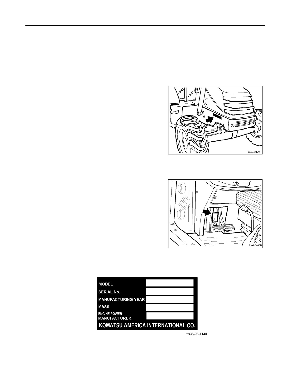
MACHINE SERIAL NUMBER
The machine serial number is stamped on the right side of the front
part of the main tractor frame.
MACHINE IDENTIFICATION PLATE
The Komatsu backhoe loaders described in this manual are provided
with the “CE” mark which certifies that they are in compliance with the
CE standards.
The identification plate is located inside the operators cab on the left
vertical wall of the frame, behind the brake pedals.
0-6 WB140-2N, WB150-2N
Page 11
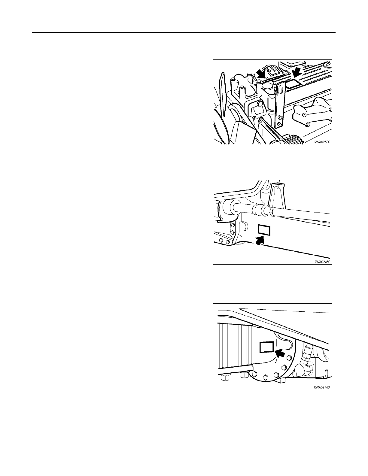
ENGINE SERIAL NUMBER AND EMISSION LABEL
The engine serial number is stamped on a plate located on top of the
engine valve cover.
The emission label is located on the right side of the valve cover.
FRONT AXLE SERIAL NUMBER
The serial number for the front axle is stamped on a plate located on the
right side of the axle housing.
INTRODUCTION
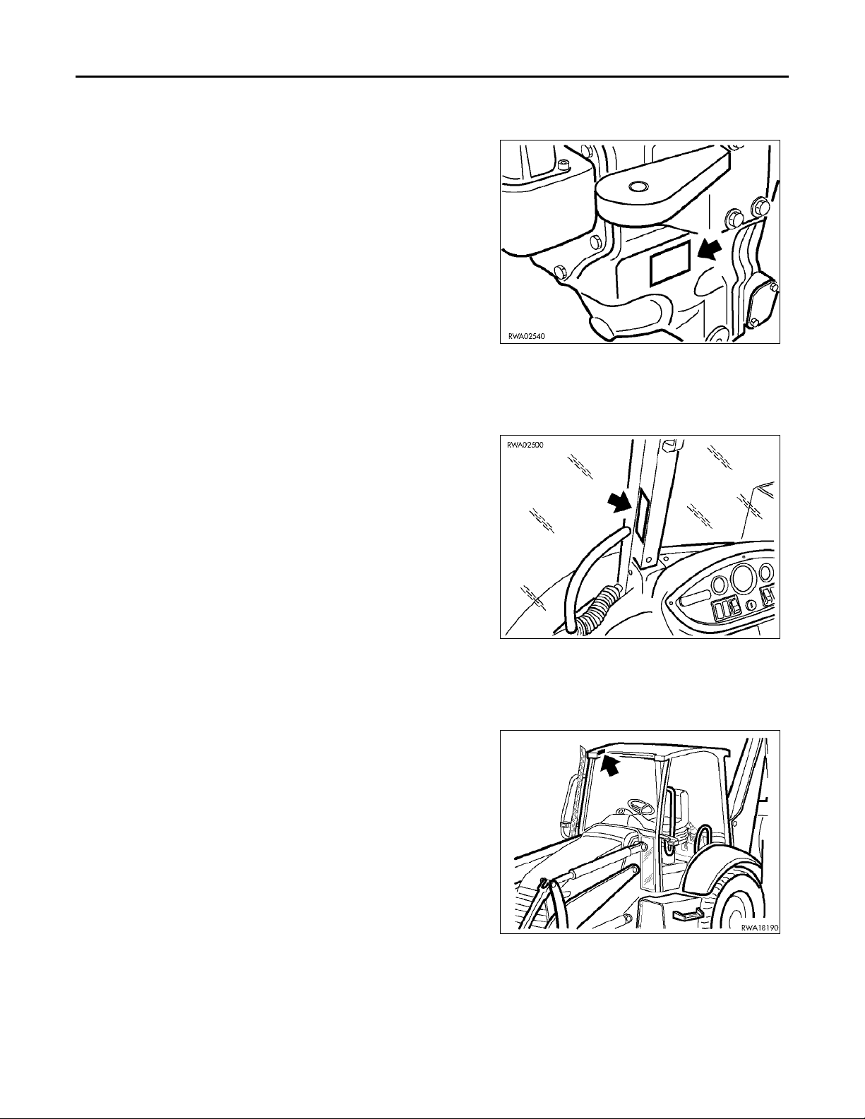
REAR AXLE SERIAL NUMBER
The serial number for the rear axle is stamped on a plate located on the
right side of the axle housing.
WB140-2N, WB150-2N 0-7
Page 12
INTRODUCTION
TRANSMISSION SERIAL NUMBER
The serial number for the transmission is stamped on a plate located on
the right side of the transmission case.
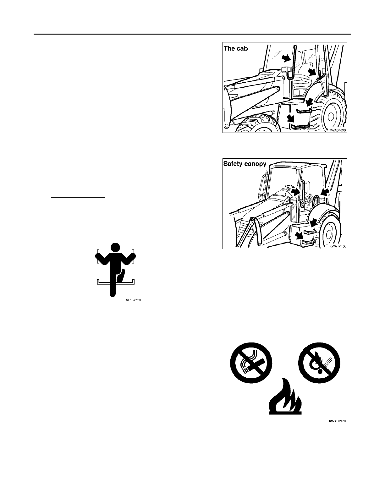
CAB SERIAL NUMBER
The serial number for the cab is stamped on a plate located on the right
center pillar.
CANOPY SERIAL NUMBER
The serial number for the canopy is stamped on the plate located on the
inside upper right corner.
0-8 WB140-2N, WB150-2N
Page 13

SERIAL NUMBERS AND DEALER INFORMATION
MODEL: WB140-2N / WB150-2N
Machine #
Engine #
Front axle #
Rear axle #
Transmission #
Cab or Canopy #
INTRODUCTION
Dealer:
Address:
Phone #
Contacts:
NOTES:
WB140-2N, WB150-2N 0-9
Page 14

INTRODUCTION
CONTENTS
INTRODUCTION
FOREWORD . . . . . . . . . . . . . . . . . . . . . . . . . . . . . . . . . . . . . . . . . . . . . . . . . . . . . . . . . . . . . . . . . . . . . 0-2
SAFETY INFORMATION . . . . . . . . . . . . . . . . . . . . . . . . . . . . . . . . . . . . . . . . . . . . . . . . . . . . . . . . . . 0-3
APPROVED AND NON-APPROVED USES . . . . . . . . . . . . . . . . . . . . . . . . . . . . . . . . . . . . . . . . . . . 0-4
APPROVED . . . . . . . . . . . . . . . . . . . . . . . . . . . . . . . . . . . . . . . . . . . . . . . . . . . . . . . . . . . . . . . . . . 0-4
NON-APPROVED . . . . . . . . . . . . . . . . . . . . . . . . . . . . . . . . . . . . . . . . . . . . . . . . . . . . . . . . . . . . . 0-4
PRODUCT INFORMATION . . . . . . . . . . . . . . . . . . . . . . . . . . . . . . . . . . . . . . . . . . . . . . . . . . . . . . . . 0-5
MAIN FEATURES . . . . . . . . . . . . . . . . . . . . . . . . . . . . . . . . . . . . . . . . . . . . . . . . . . . . . . . . . . . . . 0-5
BREAK-IN PERIOD . . . . . . . . . . . . . . . . . . . . . . . . . . . . . . . . . . . . . . . . . . . . . . . . . . . . . . . . . . . . 0-5
SYNTHETIC BIODEGRADABLE OIL TYPES . . . . . . . . . . . . . . . . . . . . . . . . . . . . . . . . . . . 0-5
PRODUCT IDENTIFICATION . . . . . . . . . . . . . . . . . . . . . . . . . . . . . . . . . . . . . . . . . . . . . . . . . . . . . . 0-6
MACHINE SERIAL NUMBER . . . . . . . . . . . . . . . . . . . . . . . . . . . . . . . . . . . . . . . . . . . . . . . . . . . 0-6
MACHINE IDENTIFICATION PLATE . . . . . . . . . . . . . . . . . . . . . . . . . . . . . . . . . . . . . . . . . . . . 0-6
ENGINE SERIAL NUMBER AND EMISSION LABEL . . . . . . . . . . . . . . . . . . . . . . . . . . . . . . . 0-7
FRONT AXLE SERIAL NUMBER . . . . . . . . . . . . . . . . . . . . . . . . . . . . . . . . . . . . . . . . . . . . . . . . 0-7
REAR AXLE SERIAL NUMBER . . . . . . . . . . . . . . . . . . . . . . . . . . . . . . . . . . . . . . . . . . . . . . . . . 0-7
TRANSMISSION SERIAL NUMBER . . . . . . . . . . . . . . . . . . . . . . . . . . . . . . . . . . . . . . . . . . . . . . 0-8
CAB SERIAL NUMBER . . . . . . . . . . . . . . . . . . . . . . . . . . . . . . . . . . . . . . . . . . . . . . . . . . . . . . . . 0-8
CANOPY SERIAL NUMBER . . . . . . . . . . . . . . . . . . . . . . . . . . . . . . . . . . . . . . . . . . . . . . . . . . . . 0-8
SERIAL NUMBERS AND DEALER INFORMATION . . . . . . . . . . . . . . . . . . . . . . . . . . . . . . . . . . . 0-9
MODEL: WB140-2N / WB150-2N . . . . . . . . . . . . . . . . . . . . . . . . . . . . . . . . . . . . . . . . . . . . . . . . . 0-9
CONTENTS . . . . . . . . . . . . . . . . . . . . . . . . . . . . . . . . . . . . . . . . . . . . . . . . . . . . . . . . . . . . . . . . . . . . . 0-10
SAFETY
GENERAL SAFETY RULES AND PRECAUTIONS . . . . . . . . . . . . . . . . . . . . . . . . . . . . . . . . . . . . . 1-2
GENERAL SAFETY RULES . . . . . . . . . . . . . . . . . . . . . . . . . . . . . . . . . . . . . . . . . . . . . . . . . . . . . 1-2
SAFETY FEATURES . . . . . . . . . . . . . . . . . . . . . . . . . . . . . . . . . . . . . . . . . . . . . . . . . . . . . . . . . . . 1-3
PERSONAL PROTECTIVE EQUIPMENT . . . . . . . . . . . . . . . . . . . . . . . . . . . . . . . . . . . . . . . . . . 1-3
UNAUTHORIZED MODIFICATIONS . . . . . . . . . . . . . . . . . . . . . . . . . . . . . . . . . . . . . . . . . . . . . 1-3
LEAVING OPERATOR’S COMPARTMENT . . . . . . . . . . . . . . . . . . . . . . . . . . . . . . . . . . . . . . . 1-4
MOUNTING AND DISMOUNTING . . . . . . . . . . . . . . . . . . . . . . . . . . . . . . . . . . . . . . . . . . . . . . . 1-5
FIRE PREVENTION FOR FUEL AND OIL . . . . . . . . . . . . . . . . . . . . . . . . . . . . . . . . . . . . . . . . . 1-5
DUST HAZARD PRECAUTIONS . . . . . . . . . . . . . . . . . . . . . . . . . . . . . . . . . . . . . . . . . . . . . . . . . 1-6
CRUSH OR PINCH POINT DANGERS . . . . . . . . . . . . . . . . . . . . . . . . . . . . . . . . . . . . . . . . . . . . 1-6
FIRE EXTINGUISHER AND FIRST AID KIT . . . . . . . . . . . . . . . . . . . . . . . . . . . . . . . . . . . . . . . 1-6
INSIDE OPERATOR’S COMPARTMENT . . . . . . . . . . . . . . . . . . . . . . . . . . . . . . . . . . . . . . . . . . 1-7
PRECAUTIONS WHEN USING ROPS . . . . . . . . . . . . . . . . . . . . . . . . . . . . . . . . . . . . . . . . . . . . . 1-7
PRECAUTIONS FOR ATTACHMENTS . . . . . . . . . . . . . . . . . . . . . . . . . . . . . . . . . . . . . . . . . . . 1-7
PRECAUTIONS BEFORE STARTING WORK OPERATIONS . . . . . . . . . . . . . . . . . . . . . . . . . . . . 1-8
PRE-OPERATIONAL CHECKS . . . . . . . . . . . . . . . . . . . . . . . . . . . . . . . . . . . . . . . . . . . . . . . . . . 1-8
PERFORM A WALK AROUND CHECK OF YOUR MACHINE . . . . . . . . . . . . . . . . . . . . . 1-8
UNDER THE HOOD . . . . . . . . . . . . . . . . . . . . . . . . . . . . . . . . . . . . . . . . . . . . . . . . . . . . . . . . 1-8
IN THE OPERATOR’S CAB . . . . . . . . . . . . . . . . . . . . . . . . . . . . . . . . . . . . . . . . . . . . . . . . . . 1-9
START-UP CHECKS . . . . . . . . . . . . . . . . . . . . . . . . . . . . . . . . . . . . . . . . . . . . . . . . . . . . . . . . 1-9
STARTING YOUR WORK OPERATIONS . . . . . . . . . . . . . . . . . . . . . . . . . . . . . . . . . . . . . . . . . 1-9
0-10 WB140-2N, WB150-2N
Page 15

INTRODUCTION
WORK SITE HAZARDS . . . . . . . . . . . . . . . . . . . . . . . . . . . . . . . . . . . . . . . . . . . . . . . . . . . . . . . 1-10
WORKING CLEARANCES . . . . . . . . . . . . . . . . . . . . . . . . . . . . . . . . . . . . . . . . . . . . . . . . . . . . . 1-10
RULES FOR ROAD TRAVEL . . . . . . . . . . . . . . . . . . . . . . . . . . . . . . . . . . . . . . . . . . . . . . . . . . . 1-11
RULES FOR TRAVELING IN REVERSE . . . . . . . . . . . . . . . . . . . . . . . . . . . . . . . . . . . . . . . . . 1-12
TRAVELING ON ICY OR SNOW-COVERED SURFACES . . . . . . . . . . . . . . . . . . . . . . . . . . . 1-12
WORKING ON LOOSE OR UNSTABLE GROUND . . . . . . . . . . . . . . . . . . . . . . . . . . . . . . . . . 1-12
PRECAUTIONS DURING MAINTENANCE OPERATIONS . . . . . . . . . . . . . . . . . . . . . . . . . . . . . 1-13
WARNING TAGS . . . . . . . . . . . . . . . . . . . . . . . . . . . . . . . . . . . . . . . . . . . . . . . . . . . . . . . . . . . . . 1-13
EQUIPMENT STORAGE . . . . . . . . . . . . . . . . . . . . . . . . . . . . . . . . . . . . . . . . . . . . . . . . . . . . . . . 1-13
WORKING UNDER THE MACHINE . . . . . . . . . . . . . . . . . . . . . . . . . . . . . . . . . . . . . . . . . . . . . 1-14
USING DROP LAMPS . . . . . . . . . . . . . . . . . . . . . . . . . . . . . . . . . . . . . . . . . . . . . . . . . . . . . . . . 1-14
KEEPING THE MACHINE CLEAN . . . . . . . . . . . . . . . . . . . . . . . . . . . . . . . . . . . . . . . . . . . . . . 1-14
RUNNING THE MACHINE DURING MAINTENANCE . . . . . . . . . . . . . . . . . . . . . . . . . . . . . 1-15
RULES FOR REFUELING THE MACHINE . . . . . . . . . . . . . . . . . . . . . . . . . . . . . . . . . . . . . . . 1-15
COOLING SYSTEM PRECAUTIONS . . . . . . . . . . . . . . . . . . . . . . . . . . . . . . . . . . . . . . . . . . . . 1-15
BATTERY PRECAUTIONS . . . . . . . . . . . . . . . . . . . . . . . . . . . . . . . . . . . . . . . . . . . . . . . . . . . . 1-16
STARTING THE MACHINE . . . . . . . . . . . . . . . . . . . . . . . . . . . . . . . . . . . . . . . . . . . . . . . . . . . . 1-16
HIGH PRESSURE HOSES . . . . . . . . . . . . . . . . . . . . . . . . . . . . . . . . . . . . . . . . . . . . . . . . . . . . . . 1-17
HIGH TEMPERATURES AREAS . . . . . . . . . . . . . . . . . . . . . . . . . . . . . . . . . . . . . . . . . . . . . . . . 1-17
ROTATING PARTS . . . . . . . . . . . . . . . . . . . . . . . . . . . . . . . . . . . . . . . . . . . . . . . . . . . . . . . . . . . 1-17
DISPOSAL OF WASTE MATERIALS . . . . . . . . . . . . . . . . . . . . . . . . . . . . . . . . . . . . . . . . . . . . 1-18
INFLATING TIRES . . . . . . . . . . . . . . . . . . . . . . . . . . . . . . . . . . . . . . . . . . . . . . . . . . . . . . . . . . . 1-18
CRITICAL PARTS . . . . . . . . . . . . . . . . . . . . . . . . . . . . . . . . . . . . . . . . . . . . . . . . . . . . . . . . . . . . 1-18
VIBRATIONS TO WHICH THE OPERATOR IS EXPOSED . . . . . . . . . . . . . . . . . . . . . . . . . . 1-18
SAFETY AND WARNING DECALS . . . . . . . . . . . . . . . . . . . . . . . . . . . . . . . . . . . . . . . . . . . . . . . . 1-19
LOCATION OF THE SAFETY DECALS . . . . . . . . . . . . . . . . . . . . . . . . . . . . . . . . . . . . . . . . . . 1-19
LOCATION OF THE PICTOGRAM DECALS . . . . . . . . . . . . . . . . . . . . . . . . . . . . . . . . . . . . . . 1-33
OPERATION
GENERAL VIEW OF MACHINE . . . . . . . . . . . . . . . . . . . . . . . . . . . . . . . . . . . . . . . . . . . . . . . . . . . . 2-2
FRONT VIEW OF MACHINE . . . . . . . . . . . . . . . . . . . . . . . . . . . . . . . . . . . . . . . . . . . . . . . . . . . . 2-2
REAR VIEW OF MACHINE . . . . . . . . . . . . . . . . . . . . . . . . . . . . . . . . . . . . . . . . . . . . . . . . . . . . . 2-3
PICTOGRAMS . . . . . . . . . . . . . . . . . . . . . . . . . . . . . . . . . . . . . . . . . . . . . . . . . . . . . . . . . . . . . . . . 2-4
WORK AREA DANGERS . . . . . . . . . . . . . . . . . . . . . . . . . . . . . . . . . . . . . . . . . . . . . . . . . . . . 2-4
MOVING OR ROTATING ENGINE COMPONENTS . . . . . . . . . . . . . . . . . . . . . . . . . . . . . . 2-4
FILLING THE HYDRAULIC SYSTEM . . . . . . . . . . . . . . . . . . . . . . . . . . . . . . . . . . . . . . . . . 2-4
ENGINE OIL FILTER . . . . . . . . . . . . . . . . . . . . . . . . . . . . . . . . . . . . . . . . . . . . . . . . . . . . . . . 2-4
BRAKE FLUID . . . . . . . . . . . . . . . . . . . . . . . . . . . . . . . . . . . . . . . . . . . . . . . . . . . . . . . . . . . . . 2-4
FUEL FILTER . . . . . . . . . . . . . . . . . . . . . . . . . . . . . . . . . . . . . . . . . . . . . . . . . . . . . . . . . . . . . . 2-5
ENGINE COOLANT . . . . . . . . . . . . . . . . . . . . . . . . . . . . . . . . . . . . . . . . . . . . . . . . . . . . . . . . 2-5
AIR FILTER . . . . . . . . . . . . . . . . . . . . . . . . . . . . . . . . . . . . . . . . . . . . . . . . . . . . . . . . . . . . . . . 2-5
ENGINE COOLANT PRESSURE WARNING . . . . . . . . . . . . . . . . . . . . . . . . . . . . . . . . . . . . 2-5
HYDRAULIC OIL LEVEL . . . . . . . . . . . . . . . . . . . . . . . . . . . . . . . . . . . . . . . . . . . . . . . . . . . . 2-5
HYDRAULIC OIL FILTER . . . . . . . . . . . . . . . . . . . . . . . . . . . . . . . . . . . . . . . . . . . . . . . . . . . 2-5
TRANSMISSION OIL LEVEL . . . . . . . . . . . . . . . . . . . . . . . . . . . . . . . . . . . . . . . . . . . . . . . . . 2-6
TRANSMISSION FLUID FILTER . . . . . . . . . . . . . . . . . . . . . . . . . . . . . . . . . . . . . . . . . . . . . . 2-6
ANCHORAGE POINT . . . . . . . . . . . . . . . . . . . . . . . . . . . . . . . . . . . . . . . . . . . . . . . . . . . . . . . 2-6
EMERGENCY EXIT . . . . . . . . . . . . . . . . . . . . . . . . . . . . . . . . . . . . . . . . . . . . . . . . . . . . . . . . 2-6
WB140-2N, WB150-2N 0-11
Page 16

INTRODUCTION
BOOM LOCK . . . . . . . . . . . . . . . . . . . . . . . . . . . . . . . . . . . . . . . . . . . . . . . . . . . . . . . . . . . . . . 2-6
SWING LOCK . . . . . . . . . . . . . . . . . . . . . . . . . . . . . . . . . . . . . . . . . . . . . . . . . . . . . . . . . . . . . 2-6
DESCRIPTION OF MACHINE OPERATION CONTROLS . . . . . . . . . . . . . . . . . . . . . . . . . . . . . . . 2-7
INSIDE THE CAB . . . . . . . . . . . . . . . . . . . . . . . . . . . . . . . . . . . . . . . . . . . . . . . . . . . . . . . . . . . . . 2-7
FRONT INSTRUMENT BEZEL AND CONTROLS . . . . . . . . . . . . . . . . . . . . . . . . . . . . . . . . . . 2-8
TRANSMISSION OIL TEMPERATURE ALERT . . . . . . . . . . . . . . . . . . . . . . . . . . . . . . . . . 2-8
ENGINE COOLANT TEMPERATURE ALERT . . . . . . . . . . . . . . . . . . . . . . . . . . . . . . . . . . 2-8
FOUR-WHEEL DRIVE (IN/OUT) INDICATOR . . . . . . . . . . . . . . . . . . . . . . . . . . . . . . . . . . 2-8
LOW FUEL ALERT . . . . . . . . . . . . . . . . . . . . . . . . . . . . . . . . . . . . . . . . . . . . . . . . . . . . . . . . . 2-8
DIRECTIONAL SIGNAL INDICATOR . . . . . . . . . . . . . . . . . . . . . . . . . . . . . . . . . . . . . . . . . 2-9
HIGH BEAM INDICATOR . . . . . . . . . . . . . . . . . . . . . . . . . . . . . . . . . . . . . . . . . . . . . . . . . . . 2-9
PARKING BRAKE AND BRAKE FLUID ALERT . . . . . . . . . . . . . . . . . . . . . . . . . . . . . . . . 2-9
DIFFERENTIAL (LOCK/UNLOCK) INDICATOR . . . . . . . . . . . . . . . . . . . . . . . . . . . . . . . . 2-9
MULTIFUNCTIONAL DIRECTIONAL SWITCH . . . . . . . . . . . . . . . . . . . . . . . . . . . . . . . . . 2-9
FOUR-WHEEL DRIVE SWITCH . . . . . . . . . . . . . . . . . . . . . . . . . . . . . . . . . . . . . . . . . . . . . 2-10
WINDSHIELD WIPER/WASHER SWITCH . . . . . . . . . . . . . . . . . . . . . . . . . . . . . . . . . . . . . 2-10
FRONT WORK LAMPS SWITCH . . . . . . . . . . . . . . . . . . . . . . . . . . . . . . . . . . . . . . . . . . . . 2-10
EMERGENCY (HAZARD) SWITCH . . . . . . . . . . . . . . . . . . . . . . . . . . . . . . . . . . . . . . . . . . 2-10
OPTIONAL EQUIPMENT SWITCH . . . . . . . . . . . . . . . . . . . . . . . . . . . . . . . . . . . . . . . . . . . 2-10
SIDE INSTRUMENT BEZEL AND CONTROLS . . . . . . . . . . . . . . . . . . . . . . . . . . . . . . . . . . . . 2-11
FUEL LEVEL GAUGE . . . . . . . . . . . . . . . . . . . . . . . . . . . . . . . . . . . . . . . . . . . . . . . . . . . . . . 2-11
TACHOMETER AND HOUR METER . . . . . . . . . . . . . . . . . . . . . . . . . . . . . . . . . . . . . . . . . 2-11
ENGINE COOLANT TEMPERATURE GAUGE . . . . . . . . . . . . . . . . . . . . . . . . . . . . . . . . . 2-12
AIR CLEANER RESTRICTION ALERT . . . . . . . . . . . . . . . . . . . . . . . . . . . . . . . . . . . . . . . 2-12
ENGINE OIL PRESSURE ALERT . . . . . . . . . . . . . . . . . . . . . . . . . . . . . . . . . . . . . . . . . . . . 2-12
GLOW PLUGS PREHEAT INDICATION . . . . . . . . . . . . . . . . . . . . . . . . . . . . . . . . . . . . . . 2-12
ALTERNATOR ALERT . . . . . . . . . . . . . . . . . . . . . . . . . . . . . . . . . . . . . . . . . . . . . . . . . . . . . 2-12
ENGINE COOLANT TEMPERATURE ALERT . . . . . . . . . . . . . . . . . . . . . . . . . . . . . . . . . 2-13
OPTIONAL EQUIPMENT ALERT . . . . . . . . . . . . . . . . . . . . . . . . . . . . . . . . . . . . . . . . . . . . 2-13
AUDIBLE WARNING SYSTEM . . . . . . . . . . . . . . . . . . . . . . . . . . . . . . . . . . . . . . . . . . . . . . 2-13
REAR WORK LAMPS . . . . . . . . . . . . . . . . . . . . . . . . . . . . . . . . . . . . . . . . . . . . . . . . . . . . . . 2-13
WINDSHIELD WIPER/WASHER SWITCH . . . . . . . . . . . . . . . . . . . . . . . . . . . . . . . . . . . . . 2-13
EMERGENCY FLASHING LIGHT SWITCH . . . . . . . . . . . . . . . . . . . . . . . . . . . . . . . . . . . 2-13
REAR HORN . . . . . . . . . . . . . . . . . . . . . . . . . . . . . . . . . . . . . . . . . . . . . . . . . . . . . . . . . . . . . 2-14
LOAD STABILIZER SWITCH (OPTIONAL) . . . . . . . . . . . . . . . . . . . . . . . . . . . . . . . . . . . 2-14
AIR CONDITIONING SWITCH (OPTIONAL) . . . . . . . . . . . . . . . . . . . . . . . . . . . . . . . . . . 2-14
IGNITION SWITCH . . . . . . . . . . . . . . . . . . . . . . . . . . . . . . . . . . . . . . . . . . . . . . . . . . . . . . . . 2-14
BLOWER SWITCH . . . . . . . . . . . . . . . . . . . . . . . . . . . . . . . . . . . . . . . . . . . . . . . . . . . . . . . . 2-14
BACKHOE POWER CONTROL SWITCH . . . . . . . . . . . . . . . . . . . . . . . . . . . . . . . . . . . . . . 2-15
BACKHOE BOOM LOCK SWITCH . . . . . . . . . . . . . . . . . . . . . . . . . . . . . . . . . . . . . . . . . . . 2-15
OPTIONAL SWITCH LOCATIONS . . . . . . . . . . . . . . . . . . . . . . . . . . . . . . . . . . . . . . . . . . . 2-15
FRONT END LOADER CONTROLS . . . . . . . . . . . . . . . . . . . . . . . . . . . . . . . . . . . . . . . . . . . . . 2-16
LOADER DECLUTCH CONTROL BUTTON . . . . . . . . . . . . . . . . . . . . . . . . . . . . . . . . . . . 2-16
DIFFERENTIAL LOCK BUTTON . . . . . . . . . . . . . . . . . . . . . . . . . . . . . . . . . . . . . . . . . . . . 2-16
BUCKET OPEN BUTTON . . . . . . . . . . . . . . . . . . . . . . . . . . . . . . . . . . . . . . . . . . . . . . . . . . . 2-17
BUCKET CLOSE BUTTON . . . . . . . . . . . . . . . . . . . . . . . . . . . . . . . . . . . . . . . . . . . . . . . . . . 2-17
FRONT END LOADER SPEED CONTROL BUTTON . . . . . . . . . . . . . . . . . . . . . . . . . . . . 2-17
GEAR SHIFT LEVER CONTROLS . . . . . . . . . . . . . . . . . . . . . . . . . . . . . . . . . . . . . . . . . . . . . . 2-18
DECLUTCH BUTTON . . . . . . . . . . . . . . . . . . . . . . . . . . . . . . . . . . . . . . . . . . . . . . . . . . . . . . 2-18
0-12 WB140-2N, WB150-2N
Page 17

INTRODUCTION
CHANGING SPEED RANGES . . . . . . . . . . . . . . . . . . . . . . . . . . . . . . . . . . . . . . . . . . . . . . . 2-18
DIRECTIONAL CONTROL LEVER . . . . . . . . . . . . . . . . . . . . . . . . . . . . . . . . . . . . . . . . . . . 2-18
BRAKES, PARKING BRAKE, ACCELERATOR AND THROTTLE CONTROL . . . . . . . . . . 2-19
BRAKE PEDALS . . . . . . . . . . . . . . . . . . . . . . . . . . . . . . . . . . . . . . . . . . . . . . . . . . . . . . . . . . 2-19
PARKING BRAKE . . . . . . . . . . . . . . . . . . . . . . . . . . . . . . . . . . . . . . . . . . . . . . . . . . . . . . . . . 2-19
ACCELERATOR PEDAL . . . . . . . . . . . . . . . . . . . . . . . . . . . . . . . . . . . . . . . . . . . . . . . . . . . 2-20
HAND THROTTLE . . . . . . . . . . . . . . . . . . . . . . . . . . . . . . . . . . . . . . . . . . . . . . . . . . . . . . . . 2-20
CAB ENVIRONMENT AND SAFETY EQUIPMENT . . . . . . . . . . . . . . . . . . . . . . . . . . . . . . . . . . . 2-21
HEATING AND VENTILATION SYSTEM . . . . . . . . . . . . . . . . . . . . . . . . . . . . . . . . . . . . . . . . 2-21
AIR CONDITIONING . . . . . . . . . . . . . . . . . . . . . . . . . . . . . . . . . . . . . . . . . . . . . . . . . . . . . . 2-21
HEATING SYSTEM . . . . . . . . . . . . . . . . . . . . . . . . . . . . . . . . . . . . . . . . . . . . . . . . . . . . . . . . 2-21
SEAT AND SEAT BELT . . . . . . . . . . . . . . . . . . . . . . . . . . . . . . . . . . . . . . . . . . . . . . . . . . . . . . . 2-22
SEAT . . . . . . . . . . . . . . . . . . . . . . . . . . . . . . . . . . . . . . . . . . . . . . . . . . . . . . . . . . . . . . . . . . . . 2-22
SEAT BELT . . . . . . . . . . . . . . . . . . . . . . . . . . . . . . . . . . . . . . . . . . . . . . . . . . . . . . . . . . . . . . 2-22
SAFETY EQUIPMENT AND STORAGE AREAS . . . . . . . . . . . . . . . . . . . . . . . . . . . . . . . . . . . 2-23
FIRE EXTINGUISHER . . . . . . . . . . . . . . . . . . . . . . . . . . . . . . . . . . . . . . . . . . . . . . . . . . . . . 2-23
FIRST AID KIT . . . . . . . . . . . . . . . . . . . . . . . . . . . . . . . . . . . . . . . . . . . . . . . . . . . . . . . . . . . . 2-23
DOCUMENT STORAGE . . . . . . . . . . . . . . . . . . . . . . . . . . . . . . . . . . . . . . . . . . . . . . . . . . . . 2-23
TOOL CASE . . . . . . . . . . . . . . . . . . . . . . . . . . . . . . . . . . . . . . . . . . . . . . . . . . . . . . . . . . . . . . 2-23
CAB AND GUARDS . . . . . . . . . . . . . . . . . . . . . . . . . . . . . . . . . . . . . . . . . . . . . . . . . . . . . . . . . . . . . 2-24
CAB . . . . . . . . . . . . . . . . . . . . . . . . . . . . . . . . . . . . . . . . . . . . . . . . . . . . . . . . . . . . . . . . . . . . . . . . 2-24
DOORS AND WINDOWS . . . . . . . . . . . . . . . . . . . . . . . . . . . . . . . . . . . . . . . . . . . . . . . . . . . 2-24
ENGINE HOOD . . . . . . . . . . . . . . . . . . . . . . . . . . . . . . . . . . . . . . . . . . . . . . . . . . . . . . . . . . . 2-25
ELECTRICAL . . . . . . . . . . . . . . . . . . . . . . . . . . . . . . . . . . . . . . . . . . . . . . . . . . . . . . . . . . . . . . . . . . . 2-26
SWITCHES AND EXTRA ACCESSORIES . . . . . . . . . . . . . . . . . . . . . . . . . . . . . . . . . . . . . . . . 2-26
OVERHEAD LAMP . . . . . . . . . . . . . . . . . . . . . . . . . . . . . . . . . . . . . . . . . . . . . . . . . . . . . . . . 2-26
BATTERY DISCONNECT . . . . . . . . . . . . . . . . . . . . . . . . . . . . . . . . . . . . . . . . . . . . . . . . . . . 2-26
OPTIONAL ELECTRICAL SWITCH LOCATION . . . . . . . . . . . . . . . . . . . . . . . . . . . . . . . 2-26
FUSES AND RELAYS . . . . . . . . . . . . . . . . . . . . . . . . . . . . . . . . . . . . . . . . . . . . . . . . . . . . . . . . . 2-27
FUSE AND RELAY PANEL LOCATION . . . . . . . . . . . . . . . . . . . . . . . . . . . . . . . . . . . . . . 2-27
DASHBOARD RELAY LOCATION . . . . . . . . . . . . . . . . . . . . . . . . . . . . . . . . . . . . . . . . . . . 2-27
FUSE AND RELAY PANEL LAY OUT . . . . . . . . . . . . . . . . . . . . . . . . . . . . . . . . . . . . . . . . 2-28
ENGINE FUSE AND RELAY LOCATION . . . . . . . . . . . . . . . . . . . . . . . . . . . . . . . . . . . . . 2-29
OPERATING THE MACHINE . . . . . . . . . . . . . . . . . . . . . . . . . . . . . . . . . . . . . . . . . . . . . . . . . . . . . 2-31
CHECKING THE FUEL SUPPLY . . . . . . . . . . . . . . . . . . . . . . . . . . . . . . . . . . . . . . . . . . . . . . . . 2-31
STARTING THE ENGINE . . . . . . . . . . . . . . . . . . . . . . . . . . . . . . . . . . . . . . . . . . . . . . . . . . . . . . 2-31
STARTING THE ENGINE IN COLD WEATHER . . . . . . . . . . . . . . . . . . . . . . . . . . . . . . . . 2-32
WARMING THE MACHINE UP . . . . . . . . . . . . . . . . . . . . . . . . . . . . . . . . . . . . . . . . . . . . . . . . . 2-33
SHUTTING THE ENGINE DOWN . . . . . . . . . . . . . . . . . . . . . . . . . . . . . . . . . . . . . . . . . . . . . . . 2-33
OPERATING THE FRONT END LOADER AND BACKHOE . . . . . . . . . . . . . . . . . . . . . . . . . . . . 2-34
OPERATING THE FRONT END LOADER . . . . . . . . . . . . . . . . . . . . . . . . . . . . . . . . . . . . . . . . 2-34
CONTROL LEVER POSITIONS . . . . . . . . . . . . . . . . . . . . . . . . . . . . . . . . . . . . . . . . . . . . . . 2-34
PERFORMING LOADING OPERATIONS . . . . . . . . . . . . . . . . . . . . . . . . . . . . . . . . . . . . . . . . . 2-35
BUCKET POSITION INDICATOR . . . . . . . . . . . . . . . . . . . . . . . . . . . . . . . . . . . . . . . . . . . . 2-35
ORGANIZING YOUR WORK AREA . . . . . . . . . . . . . . . . . . . . . . . . . . . . . . . . . . . . . . . . . . 2-35
LOADING HEAPED MATERIAL . . . . . . . . . . . . . . . . . . . . . . . . . . . . . . . . . . . . . . . . . . . . . 2-36
LOADING A TRUCK BED OR TRAILER . . . . . . . . . . . . . . . . . . . . . . . . . . . . . . . . . . . . . . 2-36
WORKING ON SLOPES WITH A LOADED BUCKET . . . . . . . . . . . . . . . . . . . . . . . . . . . 2-37
CHANGING THE FRONT BUCKET . . . . . . . . . . . . . . . . . . . . . . . . . . . . . . . . . . . . . . . . . . . . . 2-37
WB140-2N, WB150-2N 0-13
Page 18

INTRODUCTION
OPERATING THE BACKHOE . . . . . . . . . . . . . . . . . . . . . . . . . . . . . . . . . . . . . . . . . . . . . . . . . . 2-38
POSITIONING THE MACHINE . . . . . . . . . . . . . . . . . . . . . . . . . . . . . . . . . . . . . . . . . . . . . . 2-38
ADJUSTING THE DIGGING BUCKET . . . . . . . . . . . . . . . . . . . . . . . . . . . . . . . . . . . . . . . . 2-39
DIGGING METHODS . . . . . . . . . . . . . . . . . . . . . . . . . . . . . . . . . . . . . . . . . . . . . . . . . . . . . . 2-40
CHANGING THE BACKHOE BUCKET . . . . . . . . . . . . . . . . . . . . . . . . . . . . . . . . . . . . . . . . . . 2-41
ISO BACKHOE CONTROLS . . . . . . . . . . . . . . . . . . . . . . . . . . . . . . . . . . . . . . . . . . . . . . . . . . . . 2-42
KOMATSU BACKHOE CONTROLS . . . . . . . . . . . . . . . . . . . . . . . . . . . . . . . . . . . . . . . . . . . . . 2-43
SAFETY LOCK USAGE . . . . . . . . . . . . . . . . . . . . . . . . . . . . . . . . . . . . . . . . . . . . . . . . . . . . . . . . . . 2-44
BACKHOE LOCKS . . . . . . . . . . . . . . . . . . . . . . . . . . . . . . . . . . . . . . . . . . . . . . . . . . . . . . . . . . . 2-46
MOVING OR TRAVELING WITH THE MACHINE . . . . . . . . . . . . . . . . . . . . . . . . . . . . . . . . . . . . 2-47
TRAVELING . . . . . . . . . . . . . . . . . . . . . . . . . . . . . . . . . . . . . . . . . . . . . . . . . . . . . . . . . . . . . . . . . 2-47
TRAVELING ON SLOPES . . . . . . . . . . . . . . . . . . . . . . . . . . . . . . . . . . . . . . . . . . . . . . . . . . 2-48
TRAVELING OR WORKING IN SWAMPY OR WET AREAS . . . . . . . . . . . . . . . . . . . . . 2-49
PARKING THE MACHINE . . . . . . . . . . . . . . . . . . . . . . . . . . . . . . . . . . . . . . . . . . . . . . . . . . . . . . . . 2-50
FOR SHORT OR LONG PERIODS OF TIME . . . . . . . . . . . . . . . . . . . . . . . . . . . . . . . . . . . . . . 2-50
PARKING ON AN INCLINE . . . . . . . . . . . . . . . . . . . . . . . . . . . . . . . . . . . . . . . . . . . . . . . . . 2-51
TRANSPORTING THE MACHINE . . . . . . . . . . . . . . . . . . . . . . . . . . . . . . . . . . . . . . . . . . . . . . . . . . 2-52
LOADING AND SECURING THE MACHINE . . . . . . . . . . . . . . . . . . . . . . . . . . . . . . . . . . . . . 2-52
EMERGENCY RECOVERY . . . . . . . . . . . . . . . . . . . . . . . . . . . . . . . . . . . . . . . . . . . . . . . . . . . . . . . 2-53
HOW TO MOVE THE MACHINE . . . . . . . . . . . . . . . . . . . . . . . . . . . . . . . . . . . . . . . . . . . . . . . 2-53
PRECAUTIONS DURING SEASONAL CHANGES . . . . . . . . . . . . . . . . . . . . . . . . . . . . . . . . . . . . 2-54
COLD SEASONS . . . . . . . . . . . . . . . . . . . . . . . . . . . . . . . . . . . . . . . . . . . . . . . . . . . . . . . . . . . . . 2-54
FUEL AND LUBRICANTS . . . . . . . . . . . . . . . . . . . . . . . . . . . . . . . . . . . . . . . . . . . . . . . . . . 2-54
COOLANT . . . . . . . . . . . . . . . . . . . . . . . . . . . . . . . . . . . . . . . . . . . . . . . . . . . . . . . . . . . . . . . 2-54
BATTERY . . . . . . . . . . . . . . . . . . . . . . . . . . . . . . . . . . . . . . . . . . . . . . . . . . . . . . . . . . . . . . . . 2-54
WARM SEASONS . . . . . . . . . . . . . . . . . . . . . . . . . . . . . . . . . . . . . . . . . . . . . . . . . . . . . . . . . . . . 2-55
BASIC TROUBLESHOOTING . . . . . . . . . . . . . . . . . . . . . . . . . . . . . . . . . . . . . . . . . . . . . . . . . . . . . 2-56
THE BATTERY . . . . . . . . . . . . . . . . . . . . . . . . . . . . . . . . . . . . . . . . . . . . . . . . . . . . . . . . . . . . . . 2-56
SERVICING THE BATTERY . . . . . . . . . . . . . . . . . . . . . . . . . . . . . . . . . . . . . . . . . . . . . . . . 2-56
REMOVAL AND INSTALLATION . . . . . . . . . . . . . . . . . . . . . . . . . . . . . . . . . . . . . . . . . . . 2-56
STARTING THE ENGINE WITH BOOSTER CABLE . . . . . . . . . . . . . . . . . . . . . . . . . . . . 2-57
ELECTRICAL CIRCUITS . . . . . . . . . . . . . . . . . . . . . . . . . . . . . . . . . . . . . . . . . . . . . . . . . . . . . . 2-59
HYDRAULIC SYSTEM . . . . . . . . . . . . . . . . . . . . . . . . . . . . . . . . . . . . . . . . . . . . . . . . . . . . . . . . 2-59
BRAKING SYSTEM . . . . . . . . . . . . . . . . . . . . . . . . . . . . . . . . . . . . . . . . . . . . . . . . . . . . . . . . . . 2-60
TORQUE CONVERTER SYSTEM . . . . . . . . . . . . . . . . . . . . . . . . . . . . . . . . . . . . . . . . . . . . . . . 2-60
ENGINE . . . . . . . . . . . . . . . . . . . . . . . . . . . . . . . . . . . . . . . . . . . . . . . . . . . . . . . . . . . . . . . . . . . . . 2-61
MAINTENANCE
GUIDE TO MAINTENANCE . . . . . . . . . . . . . . . . . . . . . . . . . . . . . . . . . . . . . . . . . . . . . . . . . . . . . . . 3-2
MAINTENANCE NOTES . . . . . . . . . . . . . . . . . . . . . . . . . . . . . . . . . . . . . . . . . . . . . . . . . . . . . . . . . . 3-3
NOTES REGARDING THE ENGINE . . . . . . . . . . . . . . . . . . . . . . . . . . . . . . . . . . . . . . . . . . . . . . 3-3
ENGINE OIL . . . . . . . . . . . . . . . . . . . . . . . . . . . . . . . . . . . . . . . . . . . . . . . . . . . . . . . . . . . . . . . 3-3
COOLANT . . . . . . . . . . . . . . . . . . . . . . . . . . . . . . . . . . . . . . . . . . . . . . . . . . . . . . . . . . . . . . . . 3-4
FUEL . . . . . . . . . . . . . . . . . . . . . . . . . . . . . . . . . . . . . . . . . . . . . . . . . . . . . . . . . . . . . . . . . . . . . 3-4
NOTES REGARDING THE HYDRAULIC SYSTEM . . . . . . . . . . . . . . . . . . . . . . . . . . . . . . . . . 3-4
NOTES REGARDING THE ELECTRICAL SYSTEM . . . . . . . . . . . . . . . . . . . . . . . . . . . . . . . . . 3-5
NOTES REGARDING LUBRICATION . . . . . . . . . . . . . . . . . . . . . . . . . . . . . . . . . . . . . . . . . . . . 3-5
PARTS SUBJECT TO WEAR THAT PERIODICALLY NEED CHANGING . . . . . . . . . . . . . . 3-6
0-14 WB140-2N, WB150-2N
Page 19

INTRODUCTION
FUEL, COOLANT, AND LUBRICANTS . . . . . . . . . . . . . . . . . . . . . . . . . . . . . . . . . . . . . . . . . . . . . . 3-7
PROPER SELECTION ACCORDING TO THE AMBIENT TEMPERATURE . . . . . . . . . . . . . 3-7
GREASE . . . . . . . . . . . . . . . . . . . . . . . . . . . . . . . . . . . . . . . . . . . . . . . . . . . . . . . . . . . . . . . . . . . . . 3-8
HOMOLOGATED (HEES) SYNTHETIC BIODEGRADABLE LUBRICANTS . . . . . . . . . . . . . . 3-11
LUBRICATION DIAGRAMS . . . . . . . . . . . . . . . . . . . . . . . . . . . . . . . . . . . . . . . . . . . . . . . . . . . . . . 3-12
GENERAL . . . . . . . . . . . . . . . . . . . . . . . . . . . . . . . . . . . . . . . . . . . . . . . . . . . . . . . . . . . . . . . . . . . 3-12
MULTIPURPOSE BUCKET AND PALLET FORKS . . . . . . . . . . . . . . . . . . . . . . . . . . . . . . . . . 3-13
FRONT BUCKET QUICK COUPLINGS . . . . . . . . . . . . . . . . . . . . . . . . . . . . . . . . . . . . . . . . . . 3-14
TELESCOPIC ARM . . . . . . . . . . . . . . . . . . . . . . . . . . . . . . . . . . . . . . . . . . . . . . . . . . . . . . . . . . . 3-15
PERIODIC REPLACEMENT OF COMPONENTS CONNECTED WITH SAFETY . . . . . . . . . . . 3-16
CRITICAL PARTS FOR SAFETY . . . . . . . . . . . . . . . . . . . . . . . . . . . . . . . . . . . . . . . . . . . . . . . . 3-17
FUEL SUPPLY SYSTEM . . . . . . . . . . . . . . . . . . . . . . . . . . . . . . . . . . . . . . . . . . . . . . . . . . . . 3-17
DELIVERY / RETURN HYDRAULIC SYSTEM . . . . . . . . . . . . . . . . . . . . . . . . . . . . . . . . . 3-18
LOADER AND BACKHOE HYDRAULIC SYSTEM . . . . . . . . . . . . . . . . . . . . . . . . . . . . . 3-19
OPERATOR’S SAFETY . . . . . . . . . . . . . . . . . . . . . . . . . . . . . . . . . . . . . . . . . . . . . . . . . . . . . 3-20
STANDARD TIGHTENING TORQUE . . . . . . . . . . . . . . . . . . . . . . . . . . . . . . . . . . . . . . . . . . . . . . . 3-21
STANDARD TIGHTENING TORQUE FOR BOLTS AND NUTS . . . . . . . . . . . . . . . . . . . . . . 3-21
SPECIFIC TIGHTENING TORQUES . . . . . . . . . . . . . . . . . . . . . . . . . . . . . . . . . . . . . . . . . . . . . 3-21
MAINTENANCE PLAN . . . . . . . . . . . . . . . . . . . . . . . . . . . . . . . . . . . . . . . . . . . . . . . . . . . . . . . . . . . 3-22
CHECKS BEFORE STARTING . . . . . . . . . . . . . . . . . . . . . . . . . . . . . . . . . . . . . . . . . . . . . . . . . . . . . 3-26
VARIOUS CHECKS . . . . . . . . . . . . . . . . . . . . . . . . . . . . . . . . . . . . . . . . . . . . . . . . . . . . . . . . . . . 3-26
CHECKING FUEL LEVEL . . . . . . . . . . . . . . . . . . . . . . . . . . . . . . . . . . . . . . . . . . . . . . . . . . . . . 3-26
CHECKING COOLANT LEVEL . . . . . . . . . . . . . . . . . . . . . . . . . . . . . . . . . . . . . . . . . . . . . . . . . 3-27
CHECKING ENGINE OIL LEVEL . . . . . . . . . . . . . . . . . . . . . . . . . . . . . . . . . . . . . . . . . . . . . . . 3-27
CHECKING HYDRAULIC SYSTEM OIL LEVEL . . . . . . . . . . . . . . . . . . . . . . . . . . . . . . . . . . 3-28
DRAINING WATER SEPARATOR . . . . . . . . . . . . . . . . . . . . . . . . . . . . . . . . . . . . . . . . . . . . . . 3-29
MAINTENANCE EVERY 10 HOURS OF OPERATION . . . . . . . . . . . . . . . . . . . . . . . . . . . . . . . . 3-29
LUBRICATING JOINTS (GREASE FITTINGS) . . . . . . . . . . . . . . . . . . . . . . . . . . . . . . . . . . . . 3-29
JOINT LUBRICATION POINTS . . . . . . . . . . . . . . . . . . . . . . . . . . . . . . . . . . . . . . . . . . . . . . . . . 3-30
FRONT LOADER LUBRICATION LOCATIONS . . . . . . . . . . . . . . . . . . . . . . . . . . . . . . . . 3-30
BACKHOE LUBRICATION LOCATIONS . . . . . . . . . . . . . . . . . . . . . . . . . . . . . . . . . . . . . 3-31
MAINTENANCE AFTER FIRST 50 HOURS OF OPERATION . . . . . . . . . . . . . . . . . . . . . . . . . . . 3-32
MAINTENANCE EVERY 50 HOURS OF OPERATION . . . . . . . . . . . . . . . . . . . . . . . . . . . . . . . . 3-32
CHECKING RADIATOR FLUID LEVEL . . . . . . . . . . . . . . . . . . . . . . . . . . . . . . . . . . . . . . . . . . 3-32
CHECKING BRAKE SYSTEM OIL LEVEL . . . . . . . . . . . . . . . . . . . . . . . . . . . . . . . . . . . . . . . 3-32
LUBRICATING PROPELLER SHAFTS . . . . . . . . . . . . . . . . . . . . . . . . . . . . . . . . . . . . . . . . . . . 3-33
LUBRICATING FRONT AXLE JOINTS CENTRAL COUPLING . . . . . . . . . . . . . . . . . . . . . . 3-34
CHECKING TIRE PRESSURE . . . . . . . . . . . . . . . . . . . . . . . . . . . . . . . . . . . . . . . . . . . . . . . . . . 3-34
CHECKING ELECTRICAL SYSTEM . . . . . . . . . . . . . . . . . . . . . . . . . . . . . . . . . . . . . . . . . . . . . 3-35
MAINTENANCE AFTER THE FIRST 250 HOURS OF OPERATION . . . . . . . . . . . . . . . . . . . . . 3-35
MAINTENANCE EVERY 250 HOURS OF OPERATION . . . . . . . . . . . . . . . . . . . . . . . . . . . . . . . 3-36
ADJUSTING FAN BELT TENSION . . . . . . . . . . . . . . . . . . . . . . . . . . . . . . . . . . . . . . . . . . . . . . 3-36
CLEANING OUTSIDE OF RADIATOR . . . . . . . . . . . . . . . . . . . . . . . . . . . . . . . . . . . . . . . . . . . 3-37
CHECKING BATTERY ELECTROLYTE LEVEL . . . . . . . . . . . . . . . . . . . . . . . . . . . . . . . . . . 3-37
CHECKING FRONT AXLE OIL LEVELS . . . . . . . . . . . . . . . . . . . . . . . . . . . . . . . . . . . . . . . . . 3-38
CHECKING REAR AXLE OIL LEVELS . . . . . . . . . . . . . . . . . . . . . . . . . . . . . . . . . . . . . . . . . . 3-38
CHECKING HYDRAULIC TRANSMISSION OIL LEVEL . . . . . . . . . . . . . . . . . . . . . . . . . . . 3-39
CHECKING WHEEL LUG NUT TORQUE . . . . . . . . . . . . . . . . . . . . . . . . . . . . . . . . . . . . . . . . 3-39
MAINTENANCE AFTER FIRST 500 HOURS OF OPERATION . . . . . . . . . . . . . . . . . . . . . . . . . . 3-40
WB140-2N, WB150-2N 0-15
Page 20

INTRODUCTION
MAINTENANCE EVERY 500 HOURS OF OPERATION . . . . . . . . . . . . . . . . . . . . . . . . . . . . . . . 3-41
CHANGING ENGINE OIL . . . . . . . . . . . . . . . . . . . . . . . . . . . . . . . . . . . . . . . . . . . . . . . . . . . . . . 3-41
CHANGING ENGINE OIL FILTER . . . . . . . . . . . . . . . . . . . . . . . . . . . . . . . . . . . . . . . . . . . . . . 3-42
CHANGING HYDRAULIC SYSTEM OIL FILTER . . . . . . . . . . . . . . . . . . . . . . . . . . . . . . . . . . 3-43
CHANGING FUEL FILTER . . . . . . . . . . . . . . . . . . . . . . . . . . . . . . . . . . . . . . . . . . . . . . . . . . . . . 3-44
FUEL FILTER . . . . . . . . . . . . . . . . . . . . . . . . . . . . . . . . . . . . . . . . . . . . . . . . . . . . . . . . . . . . . 3-44
BLEEDING THE CIRCUIT . . . . . . . . . . . . . . . . . . . . . . . . . . . . . . . . . . . . . . . . . . . . . . . . . . 3-44
DRAINING FUEL TANK . . . . . . . . . . . . . . . . . . . . . . . . . . . . . . . . . . . . . . . . . . . . . . . . . . . . . . 3-45
DRAINING HYDRAULIC OIL TANK . . . . . . . . . . . . . . . . . . . . . . . . . . . . . . . . . . . . . . . . . . . . 3-46
MAINTENANCE EVERY 1000 HOURS . . . . . . . . . . . . . . . . . . . . . . . . . . . . . . . . . . . . . . . . . . . . . 3-47
CHANGING FRONT AXLE OIL. . . . . . . . . . . . . . . . . . . . . . . . . . . . . . . . . . . . . . . . . . . . . . . . . 3-47
DIFFERENTIAL . . . . . . . . . . . . . . . . . . . . . . . . . . . . . . . . . . . . . . . . . . . . . . . . . . . . . . . . . . . 3-47
PLANETARY . . . . . . . . . . . . . . . . . . . . . . . . . . . . . . . . . . . . . . . . . . . . . . . . . . . . . . . . . . . . . 3-47
CHANGING THE REAR AXLE OIL . . . . . . . . . . . . . . . . . . . . . . . . . . . . . . . . . . . . . . . . . . . . . 3-48
DIFFERENTIAL . . . . . . . . . . . . . . . . . . . . . . . . . . . . . . . . . . . . . . . . . . . . . . . . . . . . . . . . . . . 3-48
PLANETARY . . . . . . . . . . . . . . . . . . . . . . . . . . . . . . . . . . . . . . . . . . . . . . . . . . . . . . . . . . . . . 3-48
CHANGING HYDRAULIC TRANSMISSION OIL . . . . . . . . . . . . . . . . . . . . . . . . . . . . . . . . . . 3-49
CHANGING HYDRAULIC TRANSMISSION FILTER . . . . . . . . . . . . . . . . . . . . . . . . . . . . . . 3-50
CHECKING AND ADJUSTING ENGINE VALVE CLEARANCE . . . . . . . . . . . . . . . . . . . . . . 3-50
MAINTENANCE EVERY 2000 HOURS OF OPERATION . . . . . . . . . . . . . . . . . . . . . . . . . . . . . . 3-51
CHANGING HYDRAULIC SYSTEM OIL AND CLEANING SUCTION FILTER . . . . . . . . . 3-51
CHANGING COOLANT . . . . . . . . . . . . . . . . . . . . . . . . . . . . . . . . . . . . . . . . . . . . . . . . . . . . . . . 3-53
CHANGING THE BRAKING SYSTEM OIL . . . . . . . . . . . . . . . . . . . . . . . . . . . . . . . . . . . . . . . 3-55
CHECKING ALTERNATOR AND STARTER . . . . . . . . . . . . . . . . . . . . . . . . . . . . . . . . . . . . . . 3-55
WHEN REQUIRED . . . . . . . . . . . . . . . . . . . . . . . . . . . . . . . . . . . . . . . . . . . . . . . . . . . . . . . . . . . . . . 3-56
CHECKING, CLEANING, OR CHANGING AIR CLEANER CARTRIDGE . . . . . . . . . . . . . . 3-56
CHECKING AND CLEANING CAB AIR FILTERS . . . . . . . . . . . . . . . . . . . . . . . . . . . . . . . . . 3-57
BLEEDING BRAKE SYSTEM . . . . . . . . . . . . . . . . . . . . . . . . . . . . . . . . . . . . . . . . . . . . . . . . . . 3-58
FLUSHING COOLING SYSTEM . . . . . . . . . . . . . . . . . . . . . . . . . . . . . . . . . . . . . . . . . . . . . . . . 3-59
CLEANING THE WATER SEPARATOR . . . . . . . . . . . . . . . . . . . . . . . . . . . . . . . . . . . . . . . . . . 3-61
CHECKING AND ADJUSTING FRONT WHEEL TOE-IN . . . . . . . . . . . . . . . . . . . . . . . . . . . . 3-61
CHECKING AND ADJUSTING PARKING BRAKE . . . . . . . . . . . . . . . . . . . . . . . . . . . . . . . . . 3-62
CHECK . . . . . . . . . . . . . . . . . . . . . . . . . . . . . . . . . . . . . . . . . . . . . . . . . . . . . . . . . . . . . . . . . . 3-62
ADJUSTMENT . . . . . . . . . . . . . . . . . . . . . . . . . . . . . . . . . . . . . . . . . . . . . . . . . . . . . . . . . . . . 3-62
CHECKING THE BRAKING EFFICIENCY . . . . . . . . . . . . . . . . . . . . . . . . . . . . . . . . . . . . . . . . 3-63
CHECKING AND ADJUSTING BRAKE PEDAL STROKE . . . . . . . . . . . . . . . . . . . . . . . . . . . 3-64
ADJUSTING AUTOMATIC RETURN OF FRONT BUCKET TO THE DIGGING POSITION 3-64
MAINTENANCE INTERVALS IN CASE OF DEMOLITION HAMMER USE . . . . . . . . . . . . . . . 3-65
CHANGING HYDRAULIC OIL FILTER . . . . . . . . . . . . . . . . . . . . . . . . . . . . . . . . . . . . . . . . . . 3-65
CHANGING HYDRAULIC OIL . . . . . . . . . . . . . . . . . . . . . . . . . . . . . . . . . . . . . . . . . . . . . . . . . 3-65
LONG TERM STORAGE . . . . . . . . . . . . . . . . . . . . . . . . . . . . . . . . . . . . . . . . . . . . . . . . . . . . . . . . . . 3-66
BEFORE STORAGE . . . . . . . . . . . . . . . . . . . . . . . . . . . . . . . . . . . . . . . . . . . . . . . . . . . . . . . . . . . 3-66
DURING STORAGE . . . . . . . . . . . . . . . . . . . . . . . . . . . . . . . . . . . . . . . . . . . . . . . . . . . . . . . . . . 3-67
AFTER STORAGE . . . . . . . . . . . . . . . . . . . . . . . . . . . . . . . . . . . . . . . . . . . . . . . . . . . . . . . . . . . . 3-67
SPECIFICATIONS
TECHNICAL DATA . . . . . . . . . . . . . . . . . . . . . . . . . . . . . . . . . . . . . . . . . . . . . . . . . . . . . . . . . . . . . . . 4-2
STANDARD OVERALL DIMENSIONS . . . . . . . . . . . . . . . . . . . . . . . . . . . . . . . . . . . . . . . . . . . 4-2
0-16 WB140-2N, WB150-2N
Page 21

INTRODUCTION
TECHNICAL CHARACTERISTICS WB140-2N (ASPIRATED ENGINE) . . . . . . . . . . . . . . . . 4-3
TOTAL MASS . . . . . . . . . . . . . . . . . . . . . . . . . . . . . . . . . . . . . . . . . . . . . . . . . . . . . . . . . . . . . 4-3
STANDARD BUCKET CAPACITY . . . . . . . . . . . . . . . . . . . . . . . . . . . . . . . . . . . . . . . . . . . . 4-3
ASPIRATED ENGINE . . . . . . . . . . . . . . . . . . . . . . . . . . . . . . . . . . . . . . . . . . . . . . . . . . . . . . . 4-3
ELECTRICAL SYSTEM . . . . . . . . . . . . . . . . . . . . . . . . . . . . . . . . . . . . . . . . . . . . . . . . . . . . . 4-3
TRAVEL SPEEDS . . . . . . . . . . . . . . . . . . . . . . . . . . . . . . . . . . . . . . . . . . . . . . . . . . . . . . . . . . 4-3
TIRES . . . . . . . . . . . . . . . . . . . . . . . . . . . . . . . . . . . . . . . . . . . . . . . . . . . . . . . . . . . . . . . . . . . . 4-3
TECHNICAL CHARACTERISTICS WB140-2N (TURBOCHARGED ENGINE) . . . . . . . . . . . 4-4
TOTAL MASS . . . . . . . . . . . . . . . . . . . . . . . . . . . . . . . . . . . . . . . . . . . . . . . . . . . . . . . . . . . . . 4-4
STANDARD BUCKET CAPACITY . . . . . . . . . . . . . . . . . . . . . . . . . . . . . . . . . . . . . . . . . . . . 4-4
ASPIRATED ENGINE . . . . . . . . . . . . . . . . . . . . . . . . . . . . . . . . . . . . . . . . . . . . . . . . . . . . . . . 4-4
ELECTRICAL SYSTEM . . . . . . . . . . . . . . . . . . . . . . . . . . . . . . . . . . . . . . . . . . . . . . . . . . . . . 4-4
TRAVEL SPEEDS . . . . . . . . . . . . . . . . . . . . . . . . . . . . . . . . . . . . . . . . . . . . . . . . . . . . . . . . . . 4-4
TIRES . . . . . . . . . . . . . . . . . . . . . . . . . . . . . . . . . . . . . . . . . . . . . . . . . . . . . . . . . . . . . . . . . . . . 4-4
TECHNICAL CHARACTERISTICS WB150-2N . . . . . . . . . . . . . . . . . . . . . . . . . . . . . . . . . . . . . 4-5
TOTAL MASS . . . . . . . . . . . . . . . . . . . . . . . . . . . . . . . . . . . . . . . . . . . . . . . . . . . . . . . . . . . . . 4-5
STANDARD BUCKET CAPACITY . . . . . . . . . . . . . . . . . . . . . . . . . . . . . . . . . . . . . . . . . . . . 4-5
ASPIRATED ENGINE . . . . . . . . . . . . . . . . . . . . . . . . . . . . . . . . . . . . . . . . . . . . . . . . . . . . . . . 4-5
ELECTRICAL SYSTEM . . . . . . . . . . . . . . . . . . . . . . . . . . . . . . . . . . . . . . . . . . . . . . . . . . . . . 4-5
TRAVEL SPEEDS . . . . . . . . . . . . . . . . . . . . . . . . . . . . . . . . . . . . . . . . . . . . . . . . . . . . . . . . . . 4-5
TIRES . . . . . . . . . . . . . . . . . . . . . . . . . . . . . . . . . . . . . . . . . . . . . . . . . . . . . . . . . . . . . . . . . . . . 4-5
LIFTING CAPACITIES . . . . . . . . . . . . . . . . . . . . . . . . . . . . . . . . . . . . . . . . . . . . . . . . . . . . . . . . . 4-6
SYMBOLS . . . . . . . . . . . . . . . . . . . . . . . . . . . . . . . . . . . . . . . . . . . . . . . . . . . . . . . . . . . . . . . . . 4-6
LIFTING CAPACITY WB140-2N . . . . . . . . . . . . . . . . . . . . . . . . . . . . . . . . . . . . . . . . . . . . . . 4-7
LIFTING CAPACITY WB150-2N . . . . . . . . . . . . . . . . . . . . . . . . . . . . . . . . . . . . . . . . . . . . . . 4-9
OPTIONAL ATTACHMENTS
AUTHORIZED OPTIONAL EQUIPMENT . . . . . . . . . . . . . . . . . . . . . . . . . . . . . . . . . . . . . . . . . . . . . 5-2
BASIC PRECAUTIONS . . . . . . . . . . . . . . . . . . . . . . . . . . . . . . . . . . . . . . . . . . . . . . . . . . . . . . . . . 5-2
OPTIONAL EQUIPMENT MEASUREMENTS FOR (WB140-2N) . . . . . . . . . . . . . . . . . . . . . . . 5-3
FRONT END LOADER . . . . . . . . . . . . . . . . . . . . . . . . . . . . . . . . . . . . . . . . . . . . . . . . . . . . . . 5-3
BACKHOE UNIT . . . . . . . . . . . . . . . . . . . . . . . . . . . . . . . . . . . . . . . . . . . . . . . . . . . . . . . . . . . 5-3
OPTIONAL EQUIPMENT MEASUREMENTS FOR (WB150-2N) . . . . . . . . . . . . . . . . . . . . . . . 5-4
FRONT END LOADER . . . . . . . . . . . . . . . . . . . . . . . . . . . . . . . . . . . . . . . . . . . . . . . . . . . . . . 5-4
BACKHOE UNIT . . . . . . . . . . . . . . . . . . . . . . . . . . . . . . . . . . . . . . . . . . . . . . . . . . . . . . . . . . . 5-4
FRONT EQUIPMENT QUICK COUPLING DEVICES . . . . . . . . . . . . . . . . . . . . . . . . . . . . . . . . 5-5
MANUAL CONTROL QUICK COUPLING . . . . . . . . . . . . . . . . . . . . . . . . . . . . . . . . . . . . . . 5-5
MULTIPURPOSE BUCKET . . . . . . . . . . . . . . . . . . . . . . . . . . . . . . . . . . . . . . . . . . . . . . . . . . 5-6
BUCKET OPERATION . . . . . . . . . . . . . . . . . . . . . . . . . . . . . . . . . . . . . . . . . . . . . . . . . . . . . . . . . 5-7
DESCRIPTION . . . . . . . . . . . . . . . . . . . . . . . . . . . . . . . . . . . . . . . . . . . . . . . . . . . . . . . . . . . . . 5-7
BUCKET USES . . . . . . . . . . . . . . . . . . . . . . . . . . . . . . . . . . . . . . . . . . . . . . . . . . . . . . . . . . . . . 5-7
PALLET FORKS KIT . . . . . . . . . . . . . . . . . . . . . . . . . . . . . . . . . . . . . . . . . . . . . . . . . . . . . . . . 5-8
REMOVING AND INSTALLING THE FORKS . . . . . . . . . . . . . . . . . . . . . . . . . . . . . . . . . . . 5-8
BACKHOE TELESCOPIC ARM . . . . . . . . . . . . . . . . . . . . . . . . . . . . . . . . . . . . . . . . . . . . . . . . . . . . 5-10
DESCRIPTION AND CONTROL . . . . . . . . . . . . . . . . . . . . . . . . . . . . . . . . . . . . . . . . . . . . . . . . 5-10
SAFETY LOCKS . . . . . . . . . . . . . . . . . . . . . . . . . . . . . . . . . . . . . . . . . . . . . . . . . . . . . . . . . . 5-10
MAINTENANCE . . . . . . . . . . . . . . . . . . . . . . . . . . . . . . . . . . . . . . . . . . . . . . . . . . . . . . . . . . 5-11
DEMOLITION HAMMER . . . . . . . . . . . . . . . . . . . . . . . . . . . . . . . . . . . . . . . . . . . . . . . . . . . . . . . . . 5-13
WB140-2N, WB150-2N 0-17
Page 22

INTRODUCTION
DESCRIPTION AND CONTROL . . . . . . . . . . . . . . . . . . . . . . . . . . . . . . . . . . . . . . . . . . . . . . . . 5-13
RULES FOR HAMMER USAGE . . . . . . . . . . . . . . . . . . . . . . . . . . . . . . . . . . . . . . . . . . . . . . 5-14
ALWAYS AVOID THE FOLLOWING USES: . . . . . . . . . . . . . . . . . . . . . . . . . . . . . . . . . . . 5-15
INSTALLATION AND REMOVAL OF THE DEMOLITION HAMMER . . . . . . . . . . . . . 5-17
CLAMSHELL BUCKET . . . . . . . . . . . . . . . . . . . . . . . . . . . . . . . . . . . . . . . . . . . . . . . . . . . . . . . . . . 5-18
DESCRIPTION AND CONTROL . . . . . . . . . . . . . . . . . . . . . . . . . . . . . . . . . . . . . . . . . . . . . . . . 5-18
INSTALLATION AND REMOVAL OF THE CLAMSHELL BUCKET . . . . . . . . . . . . . . . 5-19
OPERATING THE CLAMSHELL BUCKET . . . . . . . . . . . . . . . . . . . . . . . . . . . . . . . . . . . . 5-19
HYDRAULIC JACK HAMMER . . . . . . . . . . . . . . . . . . . . . . . . . . . . . . . . . . . . . . . . . . . . . . . . . . . . 5-20
DESCRIPTION AND CONTROL . . . . . . . . . . . . . . . . . . . . . . . . . . . . . . . . . . . . . . . . . . . . . . . . 5-20
CONNECTING AND REMOVING THE JACK HAMMER . . . . . . . . . . . . . . . . . . . . . . . . 5-21
USING THE JACK HAMMER . . . . . . . . . . . . . . . . . . . . . . . . . . . . . . . . . . . . . . . . . . . . . . . 5-21
0-18 WB140-2N, WB150-2N
Page 23

1SAFETY
WARNING!
Read and follow all safety precautions. Failure to do so may
result in serious injury or death.
This safety section also contains precautions for optional
equipment and attachments.
WB140-2N, WB150-2N
1-1
Page 24

SAFETY
GENERAL SAFETY RULES AND PRECAUTIONS
GENERAL SAFETY RULES
Only trained and authorized personnel shall be allowed to operate and service this machine.
Before operating this machine it is important to study the operator’s manual thoroughly and become familiar with all
controls and safety decals. Keep this manual with your machine at all times for easy reference.
Safety must always be the operator’s most important concern. Never operate a machine that is unsafe or in poor operating condition.
Always perform a pre-operational check on your machine before operating it.
If the machine is equipped with a seat belt and rollover protective structure, OSHA law requires the operator remain within the
confines of the rollover protective structure, with the seat belt fastened snugly around their waist before operating the machine.
OSHA law states if your equipment is designed for operation by one person, it is for one person only, never allow other personnel to ride on your machine.
Never leave your machine running and unattended. Always park the machine in a level area, lower any work equipment to the
ground, set the parking brake, lock the controls and turn the engine off before exiting the operator’s compartment.
Be sure that all personnel are at least 12 m (40 ft.) away from any point on the machine before moving or operating themachine. Never allow anyone to stand near the machine while in operation. Remember, the larger the machine the more restricted
your visibility will be.
If pedestrians are in the area proceed slowly and sound your horn. Keep in mind, pedestrians have the right away, and a loaded
or smaller machine has the right away over an unloaded machine.
Never use your machine for tasks it was not designed for, damage to the machine or injury to the operator may result.
Follow all safety rules, precautions, and instructions when operating or performing maintenance on the machine.
It is the owner and /or operator’s responsibility to replace any safety or warning decals if they are defaced or removed from the
machine.
Think before you act, study the job carefully. Careful operator’s and service personnel are the best insurance against accidents.
The operator of this machine must be alert, physically fit, and free from the influences of alcohol, drugs or medications that
might affect there eyesight, hearing, or reactions.
When working with another person on a work site, or during traffic control, be sure all personnel involved understand all hand
signals that are to be used.When leaving a job site for long periods of time always lower all work equipment to the ground,
neutralize work equipment controls and lock and secure your machine properly to avoid tampering by other personnel.
Never drive up to anyone standing in your path of travel. Always be sure all personnel are standing to the side when you
approach them and acknowledge your approach.
Follow all rules relating to safety as outlined in this manual and by your company, never get involved in horseplay.
1-2 WB140-2N, WB150-2N
Page 25

SAFETY
SAFETY FEATURES
Be sure all guards and covers are in place especially after servicing the machine.
Have guards or covers repaired immediately if they are damaged. See “PRECAUTIONS BEFORE STARTING WORK
OPERATIONS” on page 1-8.
Use safety equipment such as safety locks and seat belt properly.
Never remove any safety features. Always keep them in good operating condition.
Always secure the machine in a safe position: See “PARKING THE MACHINE” on page 2-50.
Seat belt: See “INSIDE OPERATOR’S COMPARTMENT” on page 1-7.
Improper use of safety features could result in serious bodily injury or death.
Be sure the machine has the correct equipment required by local rules and regulations.
PERSONAL PROTECTIVE EQUIPMENT
If your machine is equipped with safety equipment OSHA law requires
this equipment to be used when operating your machine.
Avoid loose fitting clothing, jewelry and loose long hair. These can
catch on controls or in moving parts and cause serious injury.
Wear a hard hat, safety glasses, safety shoes, mask or gloves when operating or maintaining the machine.
Always wear safety goggles, hard hat and heavy gloves, if your job
involves driving pins with a hammer or cleaning the air cleaner element
with compressed air.
Check to be sure no one is near your work area.
Check to be sure all personal protective equipment are in good condition
before using.
UNAUTHORIZED MODIFICATIONS
Any modification made without authorization from Komatsu can create a hazards. Before making any modifications, consult
your local distributor. Komatsu will not be responsible for any injury or damage caused by any unauthorized modifications.
WB140-2N, WB150-2N 1-3
Page 26
SAFETY
LEAVING OPERATOR’S COMPARTMENT
Below are listed procedures that must be followed when exiting the
operator’s cab.
1. Park the machine in a level area, lower all work equipment to the
ground.
2. Engage the parking brake.
3. Place safety lock lever for loader control in the (LOCKED) position.
4. Place safety lock lever for backhoe controls in the (LOCKED)
position.
5. Remove ignition key and keep the key with you.
6. Use the key to lock and secure all the equipment locks. This will prevent other unauthorized personnel from tampering
with your machine. Keep in mind you are responsible for securing your machine.
Remark
Never leave your machine running and unattended, even for a moment.
Work equipment posture: See “PARKING THE MACHINE” on page 2-50.
Lock:See “SAFETY LOCK USAGE” on page 2-44.
1-4 WB140-2N, WB150-2N
Page 27
MOUNTING AND DISMOUNTING
Use all hand holds and step plates on your machine.
Never jump off or on to the machine.
Before getting on the machine, if there is any oil, grease, or mud on your
shoes, rails, steps or platforms, wipe it off immediately, always keep
these areas clean, and in good condition.
Never get on or off a moving machine. These actions may lead to serious injury. Always bring the machine to a full stop.
Be sure machine is at a full stop, equipment lowered and parking brake
set before entering or exiting machine.
Never hold any control levers or the steering wheel when getting on or
off the machine.
When getting on or off the machine, always face the machine and maintain a Three Point Contac
both hands) with the handrails, steps and platforms to ensure that you
support yourself properly.
t (both feet and one hand or one foot and
SAFETY
FIRE PREVENTION FOR FUEL AND OIL
Fuel and oil are flammable. Fuel is particularly flammable and can be
hazardous. Always observe the following:
• Keep any open flames away from flammable fluids.
• Stop the engine and do not smoke when refueling.
• Tighten all fuel and oil caps securely.
• Refueling or adding oil should be made in well ventilated areas.
• Keep oil and fuel in its proper place.
• Clean up any fluid spills.
WB140-2N, WB150-2N 1-5
Page 28

SAFETY
DUST HAZARD PRECAUTIONS
Dust can be hazardous to your health if it is inhaled. Komatsu does not
use asbestos in its products, but if you handle materials containing
asbestos fibers or other dust materials during demolition operations,
always do as follows.
• Never use compressed air for cleaning.
• Use water to keep down the dust when cleaning.
• If there is a danger there may be asbestos dust in the air, operate the
machine with the wind to your back whenever possible.
• Use an approved respirator.
• Do not allow any other person into the area during operation.
• There may be a danger that non genuine parts may contain asbestos,
use only genuine Komatsu parts.
• Always observe rules and regulations related to the job site and
working environment.
CRUSH OR PINCH POINT DANGERS
Never stand under or place any part of your body between the movable
components such as the work equipment and cylinders or between the
machine and work equipment.
Keep in mind, when the work equipment is operated, the clearance will
change, this may lead to serious personal injury or death.
Never drive up to any one standing in front of a solid object or your path
of travel. The brakes could fail or the machine could slide on a slippery
surface causing injury or even death.
FIRE EXTINGUISHER AND FIRST AID KIT
As a precaution if a fire or an injury should occur, always keep a fire
extinguisher and first aid kit on your machine and do as follows:
• Be sure that fire extinguisher is in good condition and read the label
on it to ensure you know how to use it.
• Keep a first aid kit in the storage area. Check the kit periodically
and make any additions if necessary.
• Keep a list of emergency phone numbers in case of an accident.
1-6 WB140-2N, WB150-2N
Page 29

SAFETY
INSIDE OPERATOR’S COMPARTMENT
When entering the operator’s compartment, always remove mud and oil from the
soles of your shoes. If you operate the brake pedal with mud or oil on your shoes,
your foot may slip and may cause an accident.
After using the ashtray, make sure matches or cigarettes are properly extinguished and
be sure to close the lid. If the ashtray is left open, there is danger of fire.
Do not leave lighters or aerosol cans lying around the operator’s compartment. If the
temperature inside the operator’s compartment get’s too high, there is danger that the
lighter may explode.
Do not stick suction pads to the window glass. Suction pads may act as a lens and
could cause fire.
Do not use cellular telephones inside the operator’s compartment when driving or operating the machine.
Never bring any dangerous objects such as flammable or explosive items into the operator’s cab.
To ensure safety, do not use the radio or music headphones when operating the machine.
Keep the operator’s compartment clean, never allow trash or tools to accumulate, these may hinder the operation of the controls or pedals.
When operating the machine, do not put your hands or head out of the window or beyond the protection of the ROPS.
Always use the seat belt equipped with your machine. Even when using the loader or backhoe unit. Be sure the seat belt is fastened snugly around your waist before operating the machine.
PRECAUTIONS WHEN USING ROPS
The ROPS (Roll Over Protective Structure) must never be removed from the machine. The ROPS is installed to protect the
operator if the machine should roll over. It is designed not only to support the load if the machine should roll over, but also to
absorb the impact of the energy.
The ROPS fulfills all the regulations and standards for all countries, but if it is modified without authorization or is damaged,
the strength may be reduced and it may not able to fulfill its function properly.
PRECAUTIONS FOR ATTACHMENTS
When installing and using an optional attachment, read the instruction manual for the attachment and information related to
the attachments.
Do not use attachments that are not authorized by your Komatsu Distributor. Use of unauthorized attachments could create a
safety problem and adversely affect proper operation and useful life of the machine.
Any injuries, accidents, product failures resulting from use of unauthorized attachments will not be the responsibility of
Komatsu.
WB140-2N, WB150-2N 1-7
Page 30

SAFETY
PRECAUTIONS BEFORE STARTING WORK OPERATIONS
Before starting your work operations it is important to perform several procedures to be sure your equipment is in a safe operating condition. It is also important to be aware of the hazards involved when operating your machine.
PRE-OPERATIONAL CHECKS
Before starting your machine and preceding with any work operations it is important to be sure your machine is safe to operate. Below is a list of some basic items to check before any work is to begin. If any problems are found during your Pre-operational Check, have them repaired immediately. Never operate a machine that is unsafe, damaged or in need of repair.
PERFORM A WALK AROUND CHECK OF YOUR MACHINE
A. Look for any obvious missing or damaged items.
B. Check the condition of the loading and backhoe buckets, look for loose or missing attachment pins, damaged surfaces
or missing parts.
C. Check the condition of all visible hydraulic hoses, look for worn or leaking fittings, cut, scuffed or cracked hose sur-
faces. If any hose is found to be worn, cracked or leaking have it repaired or replaced immediately.
D. Check for leaking or damaged hydraulic cylinders. If any cylinder is damaged or leaking have it repaired immedi-
ately.
E. Inspect the mechanical lift, dump and backhoe arms and pivot points. Look for any loose or missing parts, cracked,
bent or damaged areas.
F. Be sure all safety decals are in place and are not damaged. Be sure they are clean and visible for all personnel to see.
G. Check the condition of the front and rear tires. Look for excess wear or cut surfaces, objects imbedded in the tire or
under inflation.
H. Check under the machine for any build-up of debris, trash or leaks. Remove any debris that is found and have the leak
checked by authorized personnel.
I. Inspect the fuel and hydraulic tanks for damage or leaks. Be sure the fill caps are installed and locked in place.
J. Be sure the steps are not damaged or covered with mud.
K. Check the condition of the cab. inspect the windows, mirrors, hand holds, work lights, directional and canopy for any
damage or missing parts. Be sure all locks are functional.
L. Check the exhaust stack, be sure it is not damaged, kinked or restricted in any way. Be sure the exhaust outlet is fac-
ing away from the cab and is not restricted.
UNDER THE HOOD
A. Open the hood and check all fluid levels. be sure they are at the specified level outlined in the maintenance section.
B. Check the engine and radiator for any build up of trash, wood chips, rubbish, leaves or other flammable materials. If
flammable materials are found as well as excess build up of oil or dust, remove the flammable material or have the
engine cleaned.
C. Be sure the hood closes properly and will lock securely to prevent tampering by others.
1-8 WB140-2N, WB150-2N
Page 31

IN THE OPERATOR’S CAB
A. Check the condition of the cab floor. Be sure it is clean and free from tools, objects, excess dirt, trash or grease.
B. Check to be sure both doors open and close properly. Be sure the right door is unlocked for safety purpose.
C. Check the windows for cleanliness, remove any stickers or objects pasted to the windows.
D. Make sure the fire extinguisher is in place and in operating condition.
E. Be sure the operator’s manual, safety manual and all cab safety decals are in place and in good condition.
F. Check to be sure the seat belt and seat works properly.
START-UP CHECKS
When performing start-up checks, be sure your machine is in a well ventilated area.
A. Start the engine and allow it to idle at a low RPM.
B. Check the operation of all gauges and warning systems. Be sure they all work and come up to normal operation.
SAFETY
C. Check the operation of all switches. Be sure the lights, wipers, directional, horn and warning flashers and alarms
work properly.
D. Check the brakes, throttle operation and steering wheel. Be sure they are clean and free from dirt or grease.
E. Check the operation of all work controls.
Remark
It is important that a pre-operational check be performed at the beginning of your work shift, even if you are
taking the machine operations over from another operator, always perform a pre-operational check before you
start work.
STARTING YOUR WORK OPERATIONS
• Before operating the machine, walk around it and check for people or objects that might be in the way.
• Do not start the engine if warning tags have been attached to the steering wheel or control levers.
• Sound your horn to warn others in the area before starting the engine or moving the machine.
• Operate the machine in a seated position only, with the seat belt fastened snugly around your waist.
• Do not allow anyone in the cab or on the machine during operations.
WB140-2N, WB150-2N 1-9
Page 32

SAFETY
WORK SITE HAZARDS
Before proceeding with any excavating operations it is important to
be aware of the hazards involved with this operation. Below is a list
outlining what to do to avoid some of these hazards.
• Before starting any excavating operations, contact all utility
departments in your area and have them identify and mark any
underground system locations, (gas lines, water lines, electrical
lines, sewer lines, etc.).
• Check your work area for any unusual ground conditions.
• Make sure your work area is as level as possible and you will
be able to maneuver your work equipment or machine easily.
• If you will be working near a high traffic area, (pedestrians or
cars) have a dedicated worker available to direct traffic or
install safety fencing around your work site.
• Always be aware of all your work site dangers or distractions.
WORKING CLEARANCES
It is always a good idea to be aware of your clearances around, in front, behind and especially above your work area or travel
rout.
Because of the additional height posed by the backhoe boom 1m (3 ft.)
is added above the canopy that cannot be seen by the operator when the
machine is in the travel posture. Some basic safety precautions to prevent risk are:
• When working or traveling in an area where clearances are a problem, travel at a slow cautious speed.
• If you are not sure of your clearances, request the aid of another
person who can guide or warn you if you get too close to objects.
• Be aware of the dangers when working around overhead electrical
lines, high humidity may pose an electrical hazard even if your
machine clears the overhead power lines.
• If your machine should come in contact with overhead electrical
lines, stop the machine and remain on the machine until the power
company clears the lines and it is safe to get off or move the machine.
• If low power lines pose a greater hazard, ask the power company to remove the lines until your work is finished.
Cable Voltage Min. Safe Distance
6.6kV 3 m 10 ft.
66.0kV 5 m 16 ft.
275kV 10 m 33 ft.
1-10 WB140-2N, WB150-2N
Page 33

RULES FOR ROAD TRAVEL
The machine is equipped with multifunction safety locks that must be
used both for maintenance operations and road travel. When necessary
to travel on roads, proceed as follows:
1. Raise the backhoe boom and engage the safety coupling for the
arm, boom and bucket.
2. Center the boom and install the lock pin.
SAFETY
3. Connect the safety cables to prevent accidental lowering of the outriggers.
4. Lock the backhoe control levers using the safety lock equipped
with the machine.
WB140-2N, WB150-2N 1-11
Page 34

SAFETY
5. Raise the loader bucket to a safe travel height of 30-40 cm (12 to 16
in) from the ground, lock the loader control levers using the safety
lock equipped with the machine.
6. Be sure the brake pedals are locked together and the 4-wheel drive
feature is disengaged.
7. Obey all traffic rules when traveling on local and state roads. Always
travel at a safe controllable speed.
RULES FOR TRAVELING IN REVERSE
Traveling in reverse may pose several hazards. Below is a list if some basic rules to follow when traveling in reverse.
• Be sure the area behind you is clear of people or objects that might be in the way
• Before moving your machine, sound the horn to warn others in your area you are moving.
• When operating in areas that may pose a hazard or has poor visibility, designate a person to direct your movements.
• Do not rely totally on you machines mirrors, keep in mind there are blind spot when using the mirrors.
TRAVELING ON ICY OR SNOW-COVERED SURFACES
If the ground is icy or covered with snow, the response of the machine to the movements of the steering wheel may not be as
precise as expected. To limit the risk resulting from reduced maneuverability, proceed as follows:
• Engage the four-wheel drive system. Remember, the four-wheel drive system will not effect your braking.
• Travel at a slow safe speed. Avoid rapped accelerations or breaking.
• Remember your stopping distances are reduced during slippery conditions.
WORKING ON LOOSE OR UNSTABLE GROUND
To limit the risk when working in these areas:
• Avoid operating the machine too close too the edge of a cliff, open trenches or ditch lines. These areas may collapse under
the weight of your machine causing serious damage to the machine or injury to the operator.
• Keep in mind after a heavy rain or thaw, the surface conditions become worse and less stable.
1-12 WB140-2N, WB150-2N
Page 35

SAFETY
PRECAUTIONS DURING MAINTENANCE OPERATIONS
All maintenance performed on this machine must only be performed by trained and authorized personnel. When performing
maintenance it is important to follow the outlined maintenance procedures and safety information outlined in this manual and
in the Shop Manual for this machine.
WARNING TAGS
Before performing any maintenance operations on this machine, position the machine on level and firm surface.
Lock the equipment controls, remove the ignition key and tag the steering wheel.
Alert all personnel in your area that the machine is down for maintenance. If necessary, tag the machine around specific points to warn others that this machine is down for maintenance.
If the machine will be down for maintenance for a long period of time,
be sure to check and see if the warning tags are still in place before you
start your repair procedures the next day.
EQUIPMENT STORAGE
Always store optional or extra work equipment in a safe and securelocation.
Store equipment in such a way that it cannot fall or cause injury to others.
WB140-2N, WB150-2N 1-13
Page 36

SAFETY
WORKING UNDER THE MACHINE
Always use approved jack stands to support the machine when performing maintenance under the chassis.
Never rely on hydraulic jacks or the machines work equipment to support the machine when working under or on the machine.
Always lower the work equipment to the ground after raising the
machine for repairs.
USING DROP LAMPS
Use only approved anti-explosion proof lamps when checking fuel, oil,
or the batteries. Non-approved lamps can cause an explosion or fire.
KEEPING THE MACHINE CLEAN
Never use flammable liquids to clean your machine. Use only approved
non-flammable cleaning solvents to clean parts or the machine itself.
Avoid using high pressure steam cleaners or caustic soaps to wash the
machine if possible. Steam cleaning or using caustic soaps may damage
paint, wiring or sensitive electrical components.
Never use high pressure water or flood the inside of the operator’s cab.
Doing so may damage sensitive electrical components.
When pressure washing, use high pressure hot water and mild grease
cutting soaps.
Always grease the machine after cleaning to push any water out of the pivot point connections.
1-14 WB140-2N, WB150-2N
Page 37

SAFETY
RUNNING THE MACHINE DURING MAINTENANCE
If during maintenance the engine must be run, be sure all work equipment is locked.
Have someone remain in the operator’s seat while the engine is running. This is if the engine must be shut down quickly.
RULES FOR REFUELING THE MACHINE
Always clean up any spills. Grease, fuel, oil or coolant spills can pose a
trip hazard if not moped up immediately.
Be sure you are adding the correct fluids to the proper location. Mixing
fluids can cause damage to internal components.
When refueling or adding any fluids, be sure you are in a well ventilatedarea.
Never smoke or allow open flames near you while you are refueling themachine.
Never mix gasoline with diesel fuel. Gasoline is extremely flammable and could cause an explosion.
Do not fill the fuel tank completely, leave room for the fuel to expand.
COOLING SYSTEM PRECAUTIONS
Never add coolant to a hot or warm engine. Always allow the engine
time to cool down completely before opening the radiator cap.
Never dump used coolant on the ground, in a lake, stream or in a sewer
system. EPA Law requires these fluids to be captured and recycled properly. Failure to do so is in violation of the law.
WB140-2N, WB150-2N 1-15
Page 38

SAFETY
BATTERY PRECAUTIONS
When working on the electrical system, disconnect the negative (-)battery cable first then the positive (+) battery cable last.
On completion of work, reconnect the positive (+) cable first then the
negative (-) cable last.
When using jumper cables to start the machine as shown below, hook
the positive (+) jumper up first, then the negative (-) jumper last to a
remote location on the chassis.
STARTING THE MACHINE
Never try to start the machine by tampering or shorting the starter terminals. Accidental movements of the machine could cause injury or even
death.
Always start the machine seated in the operators cab using the ignition
switch.
See “BASIC TROUBLESHOOTING” on page 2-56.
1-16 WB140-2N, WB150-2N
Page 39

HIGH PRESSURE HOSES
Do not use bent, cut or cracked tubing or hoses which have been previously rejected because of leaks or other defects. Faulty hoses can burst
during operation causing injury or fire.
Repair or replace any loose or faulty fuel or hydraulic lines immediately. Do not operate the machine with damaged or leaking hoses or
lines.
Remember that working hydraulic systems are always under pressure. If
you have to add or drain hydraulic fluid, service or inspect the hydraulic
system, lower the equipment to the ground and release system pressure
and residual tank pressure before starting any work.
Leaks from pressurized hydraulic lines are extremely dangerous since
the spray from them can penetrate your skin and enter the bloodstream,
or the eyes.
Always wear thick gloves and protective goggles when working on the
hydraulic systems Use a sheet of cardboard or plywood to search forleaks.
SAFETY
If you are struck by a jet of hydraulic fluid under pressure, or if you are
injured even slightly, consult a doctor immediately for appropriate treatment.
HIGH TEMPERATURES AREAS
When you stop the machine at the end of a job, remember the engine
coolant, oil, all engine parts, exhaust stack and the hydraulic system is
still hot and under pressure. If you attempt to drain engine coolant,
hydraulic fluid, or engine oil under these conditions, you expose yourself to various dangers, including the risk of serious burns.
Carry out maintenance procedures described in this manual only when
the machine has had time to cool down.
ROTATING PARTS
Take particular care near rotating parts. Keep your body at a safedistance.
If hands, clothing, or tools become entangled in the fan blades or fan
belt, severe injury may result. Keep well away from all rotating parts.
WB140-2N, WB150-2N 1-17
Page 40

SAFETY
DISPOSAL OF WASTE MATERIALS
Never dump waste fluids in a sewer system, on the ground in rivers, etc.
Always drain fluids from your machine into the appropriate containers.Never drain fluids directly onto the ground.
Obey appropriate laws and regulations when disposing of harmful
objects such as oil, fuel, filters, batteries, coolant, brake fluid and
hydraulic oil.
INFLATING TIRES
Always bear in mind that tires can burst while being inflated, causing
serious accidents. Before servicing the tires, observe the following precautions:
• Before inflating tires, always check the wheel rims, tire walls and
tread for cuts, broken cords, or other damage.
• Have a tire expert perform checks and tire maintenance.
• When inflating tires, use a protective cage, and a compressed airgun
with extension hose and pressure gauge.
• Make sure there is nobody in the vicinity before starting to inflate a
tire. Stand at the tread side of the tire to inflate it.
• Never exceed the inflation pressures specified for each type of tire.
Always check the tire pressures on both sides of the machine.
CRITICAL PARTS
Periodically some parts must be replaced due to safety purpose. Even if these parts seem to be in good condition and operating
properly they may fail at some point causing possible injury to the operator or pedestrian. Listed are some of the systems containing these components that may fail under extended use:
• Fuel supply and delivery hoses.
• Hydraulic system: main delivery hoses and tubing.
• Hydraulic hoses: all the hoses that feed and return the hydraulic fluid to and from the work equipment.
For additional information: See “PARTS SUBJECT TO WEAR THAT PERIODICALLY NEED CHANGING” on page 3-6.
VIBRATIONS TO WHICH THE OPERATOR IS EXPOSED
According to test results carried out to determine the vibrations transmitted to the operator by the machine, the upper limbs are
subjected to vibrations lower than 2.5 m/sq.sec. (8.2 ft./sq.sec.). The seated part of the body is subject to vibrations lower than
0.5 m/sq. (1.7 ft./sq.sec.).
1-18 WB140-2N, WB150-2N
Page 41

SAFETY
SAFETY AND WARNING DECALS
It is important that all safety and warning decals are in place, not damaged, covered up or removed. It is also important for the
operator to be aware of the decal content and location.
LOCATION OF THE SAFETY DECALS
• Your Komatsu Dealer can supply you with new replacement decals if the ones on the machine are damaged or missing.
• When replacing damaged or missing decals, be sure they are placed in the proper location.
• Additional safety or warning decals may be added to your machine if desired.
WB140-2N, WB150-2N 1-19
Page 42

SAFETY
1-20 WB140-2N, WB150-2N
Page 43

1. Warning Decal
Before operating this machine:
• Study the operator’s manual.
• Be aware of all the safety decals.
• Keep the operator’s manual with the machine at all times
frequent reference.
SAFETY
2. Height Decal
It is always a good idea to be aware of your clearances around,
in front, behind and especially above your work area or travel
rout.
Because of the additional height posed by the backhoe boom
1m (3 ft.) is added above the canopy when the machine is in
the travel posture.
WB140-2N, WB150-2N 1-21
Page 44

SAFETY
3. Warning Decal
• Be sure that all personnel are at least 12 m (40 ft.) away
from any point on the machine before moving the
machine.
• Never allow anyone to stand near the machine while in
operation.
• Remember, the larger the machine the more restricted your
visibility will be.
4. Sudden Movement
Shut down procedures for machine.
• Lower the loader bucket to the ground.
• Lock the loader controls.
• Curl the bucket and move the arm in towards the frame
until they stop.
• Activate the boom lock and insert the travel pin.
• Lock the backhoe controls.
• Engage the parking brake.
1-22 WB140-2N, WB150-2N
Page 45

5. Do Not Operate Tag
This warning tag must be kept with the machine at all times
and used when maintenance or repairs are performed.
6. Hydraulic Oil
Hot oil hazard.
• Turn the engine OFF.
• Allow the oil time to cool down.
• Slowly loosen the cap to relieve pressure before removing.
SAFETY
WB140-2N, WB150-2N 1-23
Page 46

SAFETY
7. Battery Decal
Battery safety precautions.
• When attaching booster cables, always make the negative
(-) connection last and at a remote location away from the
battery.
• Do not smoke or allow open flames or sparks near the bat-
tery.
• Always ware a face shield when working with batteries.
• When charging the battery always follow proper charging
instructions outlined in the “Service Manual” for this
machine.
• Avoid contact with battery acid. Sulfuric Acid may cause
burns or damage clothing or components.
• If you should come in contact with battery acid or spill
some, flush the area immediately with water.
8. Window Warning
When operating the window, be sure it is in the proper locked
position to avoid sudden unexpected movement.
1-24 WB140-2N, WB150-2N
Page 47

9. Accumulator (OPTIONAL EQUIPMENT)
If your machine is equipped wit an accumulator:
• When releasing the pressure or charging with gas for the
work equipment circuit of machines equipped with an
accumulator, be careful and follow the instructions given
for handling the accumulator.
• The accumulator is charged with high pressure nitrogen
gas which is extremely dangerous, read the following
items and be careful to handle the accumulator properly.
• Do not make any holes or bring any open flames or heat
close to the accumulator.
• Do not weld on the accumulator.
• The gas must be released before disposing of the accumu-
lator, ask your distributor to do this for you.
SAFETY
10. Air Filter
Air filter replacement:
• Keep element free of damage or oil deposits.
• For cleaning or replacement of the element, see “CHECK-
ING, CLEANING, OR CHANGING AIR CLEANER
CARTRIDGE” on page 3-56.
• Do not use oil on this filter element.
WB140-2N, WB150-2N 1-25
Page 48

SAFETY
11. Hot Coolant Hazard
To prevent the sudden release of hot coolant:
• Turn the engine OFF
• Allow the system time to cool down.
• Slowly loosen cap to relieve pressure before removing it.
12. Fuel Tank
Fuel tank precautions.
• If the fuel tank should need draining, refer to the “Mainte-
nance Manual” for proper procedures.
13. Do Not Use Ether
Use of starting aids.
• Use of any starting fluids including ether may cause explo-
sion or damage the engine.
• Never use starting aids to start the engine.
1-26 WB140-2N, WB150-2N
Page 49

14. Running Engine Warning
Rotating engine parts.
• Keep away from rotating or moving engine parts.
• Keep clear of the engine fan and fan belt.
15. Pinch Point Danger
Crush or pinch points located on the machine.
• Operate the machine from the operator’s seat only.
• During operations, never place any part of your body near
the swing area of the machine.
SAFETY
WB140-2N, WB150-2N 1-27
Page 50

SAFETY
16. Seat Belt Warning
The importance of using the sear belt equipped with your
machine.
• If the machine is equipped with a seat belt and rollover
protective structure, OSHA law requires the operator
remain within the confines of the rollover protective structure, with seat belt fastened snugly around their waist
before operating the machine.
17. Blocking Wheels
Parking on an incline.
• Always block the wheels when parking on an incline.
1-28 WB140-2N, WB150-2N
Page 51

18. Start Bypass Danger
Jump starting the machine from outside the operator’s cab.
• Never bypass the starting circuit by jump starting your
machine at the starter or any other point outside of the
operator’s cab.
• Always start the machine from the operating position in
the operator’s cab with the seat belt fastened around your
waist.
SAFETY
19. Loader Dangers
Before doing any maintenance on the front part of the machine
and the bucket, loader equipment must be raised:
• Empty the bucket completely.
• Raise the loader and install the safety bar.
• Slowly lower the loader cylinder until all movement stops.
• Lock the loader controls.
WB140-2N, WB150-2N 1-29
Page 52

SAFETY
20. ROPS Structure
Role Over Protective Structure cautions.
• Never weld, drill or cut on the ROPS
• If it becomes damaged, contact your Komatsu Dealer.
21. Brake Fluid
Use the correct fluid in the hydraulic braking system. Using the
wrong brake fluid may cause damage to the brake system
which could lead to brake failure.
22. Backhoe Levers Operation
1-30 WB140-2N, WB150-2N
Page 53

23. Loader Lever Control
This decal is for the safety lock levers and switches on your
loader work equipment. It shows:
• Loader lever lock.
• Bucket positions.
• Switch functions.
SAFETY
24. Lubrication
This decal is the lubrication chart for your machine it contains
information on:
• Lubricating time intervals.
• Lubrication points.
WB140-2N, WB150-2N 1-31
Page 54

SAFETY
25. Equipment Fuse Decal
26. Engine Fuse Decal
1-32 WB140-2N, WB150-2N
Page 55

SAFETY
LOCATION OF THE PICTOGRAM DECALS
• Your Komatsu Dealer can supply you with new replacement pic tog ram decals if the ones on the machine are damaged or
missing.
• When replacing damaged or missing pic tog ram decals, be sure they are placed in the proper location.
• Additional safety or warning decals may be added to your machine if desired.
WB140-2N, WB150-2N 1-33
Page 56

SAFETY
1-34 WB140-2N, WB150-2N
Page 57

2OPERATION
WB140-2N, WB150-2N
2-1
Page 58

OPERATION
GENERAL VIEW OF MACHINE
The views are taken from the operators seat facing forward and backward. For the front view, this would be for operator facing
the front of the machine using the front end loader or traveling with the machine. For the rear view, this would be for the operator facing the rear of the machine using the backhoe unit. Keep in mind front and rear view references for this machine are
different.
FRONT VIEW OF MACHINE
1. Front Bucket 5. Rear Axle
2. Bucket Cylinder 6. Fuel Tank
3. Bucket Arms 7. Lift Cylinder
4. Cab 8. Front Axle
2-2 WB140-2N, WB150-2N
Page 59

REAR VIEW OF MACHINE
OPERATION
1. Bucket 6. Boom Cylinder
2. Bucket Cylinder 7. Hydraulic Oil Tank
3. Arm 8. Outriggers
4. Boom 9. Boom Swing Cylinders
5. Arm Cylinder 10. Boom Support Boss
WB140-2N, WB150-2N 2-3
Page 60

OPERATION
PICTOGRAMS
The pictographs applied to the machine are there to alert the operator or maintenance personnel of system functions and possible dangers associated with the system. It is important for the operator or maintenance personnel to understand what these pictographs mean. It is also important to replace these pictographs if they become damaged or are missing. Below are a list of the
pictographs equipped with your machine and there meanings.
WORK AREA DANGERS
Do not allow personnel to approach the machine when the front end
loader is in operation. Always maintain a clearance of 12m (40 ft.) away
from any personnel any time the machine is in operating.
MOVING OR ROTATING ENGINE COMPONENTS
Always keep clear of rotating or moving parts especially in the engine compartment.
FILLING THE HYDRAULIC SYSTEM
This is only for machines using biodegradable oil. (Type HEES)
ENGINE OIL FILTER
BRAKE FLUID
2-4 WB140-2N, WB150-2N
Page 61

FUEL FILTER
ENGINE COOLANT
AIR FILTER
OPERATION
ENGINE COOLANT PRESSURE WARNING
HYDRAULIC OIL LEVEL
HYDRAULIC OIL FILTER
WB140-2N, WB150-2N 2-5
Page 62

OPERATION
TRANSMISSION OIL LEVEL
TRANSMISSION FLUID FILTER
ANCHORAGE POINT
EMERGENCY EXIT
BOOM LOCK
SWING LOCK
2-6 WB140-2N, WB150-2N
Page 63

OPERATION
DESCRIPTION OF MACHINE OPERATION CONTROLS
Before operating the machine it is important to understand all the control functions equipped with your machine. Operating the
machine without knowledge of all the controls may damage the machine, property or possibly cause injury to the operator.
INSIDE THE CAB
Direction control lever
1.
Steering wheel
2.
Front dash bezel
3.
Turn signal and dimmer switch
4.
Gear shift lever
5.
Front end loader control lever
6.
Accelerator pedal
7.
Brake pedals
8.
Side dash bezel
9.
Throttle control lever
10.
Parking brake
11.
Left backhoe wobble stick
12.
Right backhoe wobble stick
13.
Right outrigger control
14.
Left outrigger control
15.
Steering wheel adjustment (optional)
16.
WB140-2N, WB150-2N 2-7
Page 64

OPERATION
FRONT INSTRUMENT BEZEL AND CONTROLS
1. Transmission oil temperature alert
2. Engine coolant temperature alert
3. Four-wheel drive IN/OUT indicator
4. Low fuel warning
5. Directional signal indicator
6. High beam indicator
7. Parking brake and brake fluid alert
8. Differential LOCK/UNLOCK indicator
9. Multifunctional directional switch
10. Four-wheel drive switch
11. Windshield wiper/washer switch
12. Front work lamps switch
13. Emergency (HAZARD) switch
TRANSMISSION OIL TEMPERATURE ALERT
This warning light (1) comes on along with an audible alarm to
alert the operator of a transmission oil overheat condition. If this
warning and alarm should come on, immediately stop the machine
and select neutral gear. Let the transmission oil cool down with the
engine running at about 1200 RPM until the warning and alarm
stop. If this should occur repeatedly have the machine checked by
an authorized Komatsu Dealer. Do not continue to operate the
machine.
ENGINE COOLANT TEMPERATURE ALERT
This warning light (2) comes on along with an audible alarm to
alert the operator of an engine overheat condition. If this warning
and alarm should come on, immediately stop the machine and
select neutral gear. Let the engine run at about 1200 RPM until the
warning and alarm stop. If this condition should occur again, check
to make sure the radiator fins are clean and free of debris. Do not
continue to operate the machine if the engine is overheating.
FOUR-WHEEL DRIVE (IN/OUT) INDICATOR
14. Optional switch locations
When the four-wheel drive feature (3) is selected this indicator will come on indicating the four-wheel drive system is (IN)
operation. When the indicator is off, the four-wheel drive system is (OUT) of operation.
LOW FUEL ALERT
This warning light (4) comes on when there is about 17 liters (4.5 gal) of fuel left in the fuel tank. Re-fuel the machine as soon
as possible. Avoid running the machine out of fuel, damage to the injection system may result.
2-8 WB140-2N, WB150-2N
Page 65

OPERATION
DIRECTIONAL SIGNAL INDICATOR
This indicator (5) comes on intermittently when lever (9) or the
emergency (HAZARD) switch is operated.
HIGH BEAM INDICATOR
This indicator (6) comes on when the high beam is actuated by the
multifunctional directional switch (9). When the multifunctional
directional switch is actuated again, the high beam is turned off.
PARKING BRAKE AND BRAKE FLUID ALERT
This warning lamp (7) indicates the parking brake has been set or
the brake fluid level is low. This light should come on when the
parking brake is set and go off when the parking brake is released.
If this warning lamp should come on intermittently during operation or remain on after start-up, do not operate the machine. Have
the braking system checked by an authorized Komatsu Dealer.
DIFFERENTIAL (LOCK/UNLOCK) INDICATOR
When the differential lock feature is in (LOCK), the indicator lamp (8) will come on indicating it is in operation. When the
indicator lamp is off the differential is (UNLOCKED). This feature is controlled by a button in the loader control handle.
MULTIFUNCTIONAL DIRECTIONAL SWITCH
This switch (9) controls five functions:
A. Turn Left
B. Turn right
C. Horn
D. High/Low beam control
E. Flash
WB140-2N, WB150-2N 2-9
Page 66

OPERATION
FOUR-WHEEL DRIVE SWITCH
This is a two position feature. When the four-wheel drive switch
(10) is pressed the four-wheel indicator (3) comes on indicating the
machine is in four-wheel drive. When the switch is pressed again
the four-wheel drive feature is disengaged.
Remark
Do not use the four-wheel drive feature on dry roads. The
four-wheel drive feature will be automatically engaged
when the brake pedals are pressed, only
is engaged.
when 4th gear
WINDSHIELD WIPER/WASHER SWITCH
This switch operates the front windshield wipers and washer (11).
The first switch position operates the wipers. The second switch
position operates the washer.
FRONT WORK LAMPS SWITCH
This switch operates the front work lamps only (12)
EMERGENCY (HAZARD) SWITCH
This switch operates the four-way (HAZARD) flashers (13) when
turned on. This feature must be used when traveling on roadways or
when working in areas that need additional warnings.
OPTIONAL EQUIPMENT SWITCH
This location is for any optional equipment (14).
2-10 WB140-2N, WB150-2N
Page 67

SIDE INSTRUMENT BEZEL AND CONTROLS
OPERATION
8. Engine coolant temperature alert
9. Optional equipment alert
10. Audible warning alarm
11. Rear work lamps
12. Windshield wiper/washer switch
13. Emergency flashing light switch
14. Rear horn
15. Load stabilizer switch (optional)
16. Air conditioner switch (optional)
17. Ignition switch
18. Blower switch
19. Backhoe speed control switch
1. Fuel level gauge
2. Tachometer and hour meter
3. Engine coolant temperature gauge
4. Air cleaner restriction alert
5. Engine oil pressure alert
6. Glow plugs preheat indication
7. Alternator alert
FUEL LEVEL GAUGE
This gauge (1) will indicate the amount of fuel in the fuel tank.
TACHOMETER AND HOUR METER
This gauge (2) indicates the engine RPM (Revolutions Per Minute). It
also indicates the running hours on the engine
20. Backhoe boom lock switch
21. Optional switch locations
Remark
The hour meter is considered valid for calculating the maintenance or service hour intervals for the machine.
WB140-2N, WB150-2N 2-11
Page 68

OPERATION
ENGINE COOLANT TEMPERATURE GAUGE
This gauge (3) indicates the engine coolant temperature which must be
in the operating range between 80 - 85 °C (176 - 185°F) Always allow
the engine ample time to warm up to within these operating ranges
before working the machine. Never allow the engine to exceed these
operating temperatures, damage to the engine could occur.
AIR CLEANER RESTRICTION ALERT
This warning light (4) comes on when the engine air filter is
restricted. If this indicator comes on during operation, shut the
machine down and have the air filter system serviced. Do not operate the machine with a restricted air filtering system, damage to the
engine may result.
ENGINE OIL PRESSURE ALERT
This warning lamp (5) comes on along with an audible alarm to
alert the operator of an engine oil pressure loss. If this light should
come on during operation or remain on after start-up, shut the
engine down immediately. If this light does not come on when the
ignition key is turned on, have the system checked by your
Komatsu dealer. Do not operate the machine if this light comes on
intermittently or remains on, damage to the engine may result.
GLOW PLUGS PREHEAT INDICATION
In cold weather during initial start-up there is a need to preheat the
combustion air to aid in starting the engine. To use this feature, hold the ignition switch in the preheat position for approximately 30 seconds, the indicator light (6) will come on and remain on for about 30 seconds, after the light goes out the engine
may be cranked. This procedure may have to be repeated one more time. See “STARTING THE ENGINE IN COLD
WEATHER” on page 2-32.
Due to the glow plug feature equipped with this machine, do not use Ether or other starting aids. Damage
to the engine or possible injury to the operator may result.
ALTERNATOR ALERT
This warning light (7) comes on along with an audible alarm to alert the operator that the battery is not charging. If this light
should come on during operation or remain on after initial start-up have the charging system checked as soon as possible by an
authorized Komatsu Dealer.
2-12 WB140-2N, WB150-2N
Page 69

ENGINE COOLANT TEMPERATURE ALERT
This warning light (8) comes on along with an audible alarm to
alert the operator of an engine overheat condition. If this warning
and alarm should come on, immediately stop the machine and
select neutral gear. Let the engine run at about 1200 RPM until the
warning and alarm stop. If this condition should occur again, check
to make sure the radiator fins ar clean and free of debris. Do not
continue to operate the machine if the engine is overheating.
OPTIONAL EQUIPMENT ALERT
This location is for any optional equipment warning indicators (9).
AUDIBLE WARNING SYSTEM
When the ignition switch is on or the machine is in operation this audible alarm (10) will sound if:
• The engine oil pressure is low
• The engine is overheating
• The transmission is overheating
• The charging system has failed
OPERATION
REAR WORK LAMPS
This switch (11) is for the operation of the rear work lamps.
WINDSHIELD WIPER/WASHER SWITCH
This switch (12) operates the rear windshield wipers and washer.
The first position on the switch operates the wipers. The second
position operates the washer.
EMERGENCY FLASHING LIGHT SWITCH
(If equipped) This switch (13) is for operating the rotating or flashing light mounted on top of the ROPS.
WB140-2N, WB150-2N 2-13
Page 70

OPERATION
REAR HORN
This switch (14) activates the rear horn. This horn is to warn people
in the area before you start your work operations.
LOAD STABILIZER SWITCH (OPTIONAL)
When this switch (15) is turned on the load stabilizing system is
activated. This feature is used to help stabilize the machine when
the loader bucket is loaded and you are traveling on rough ground.
AIR CONDITIONING SWITCH (OPTIONAL)
When this switch (16) is turned on the air conditioning system is in
operation. When the switch is off the air conditioning system is
deactivated.
IGNITION SWITCH
The ignition switch (17) is the main switch, it is a rotary switch with
four positions
• Preheat
• OFF
• ON
• Start
BLOWER SWITCH
The blower switch (18) is used to control the operation of the blower
motor for the air circulation, it has three speeds:
• Low
• Medium
• High
See “CAB ENVIRONMENT AND SAFETY EQUIPMENT” on page 2-21.
2-14 WB140-2N, WB150-2N
Page 71

BACKHOE POWER CONTROL SWITCH
This button (19) operates the selection of oil delivery from the
hydraulic pump. When the machine is started the control automatically selects the POWER mode (switch illuminated) which gives
you the maximum brake out power at the backhoe. When the button
is pressed again, the backhoe goes into the economy mode reducing
brake out power. This feature is used for excavating light material,
operating optional attachments or using the backhoe for grading
purpose. If the machine is operated in the forward or reverse gears
the POWER mode is automatically canceled.
BACKHOE BOOM LOCK SWITCH
This button (20) operates the boom lock. This function holds the
backhoe in the parked position thus preventing hydraulic drift of
the backhoe unit.
This feature should be used when operating the front end loader or
traveling with the machine.
OPTIONAL SWITCH LOCATIONS
This switch location (21) is for optional equipment is needed.
OPERATION
WB140-2N, WB150-2N 2-15
Page 72

OPERATION
FRONT END LOADER CONTROLS
1 Loader declutch control button
2 Differential lock button
3 Bucket open button
4 Bucket close button
5 Front end loader speed control button
LOADER DECLUTCH CONTROL BUTTON
This button (1) allows the operator the option of transferring all engine
power from the drive line to the loader hydraulics when lifting heavy
loads.This feature should only be used on level ground.
• Do not use this button for more than 15 to 20 seconds.
• Do not use this button when traveling or operating on an
incline. Loss of control may result.
DIFFERENTIAL LOCK BUTTON
This button (2) allows the operator the option of locking the drive
wheels together when operating in 1st. 2nd. or 3rd. gear. It is used when
there is wheel spinning or when loading the bucket in slippery locations.
Do not use this feature when traveling on slopes. To engage
the differential lock feature, the system must disengage the
drive line first. Loss of control may result.
Remark
This function does not work in 4th. gear range. Before engaging this feature be sure the machine is stopped or
traveling at a slow speed.
2-16 WB140-2N, WB150-2N
Page 73

BUCKET OPEN BUTTON
On machines equipped with the multipurpose bucket, this button (3)
opens the top half of the bucket allowing the operator the option of converting the loader bucket into a dozer blade when filling in trenches. Or
using the bucket for picking up items.
See MULTIPURPOSE BUCKET on page 5-6
BUCKET CLOSE BUTTON
On machines equipped with the multipurpose bucket, this button (4)
closes the top half of the bucket allowing the operator to use the bucket
for scoop and loading operations.
OPERATION
FRONT END LOADER SPEED CONTROL BUTTON
When button (5) is activated, it makes it possible to utilize the maximum oil delivery from the hydraulic pump. Pressing this button allows
the operator extra power to the loader system.
Remark
It is advisable to use this feature for no more than 5 to 6 seconds during loader operation.
WB140-2N, WB150-2N 2-17
Page 74

OPERATION
GEAR SHIFT LEVER CONTROLS
The gear shift lever (1) is used to change travel speed ranges. it is
equipped with a declutching button (2) which is used to disengage the
drive line for changing speed ranges.
• Engage the gears only with the engine running at a low
RPM and the machine is traveling slowly or stopped.
• Avoid up-shifting when using the machine in heavy operations.
• Always shift the lever into a neutral position (N) when
parking the machine and set the parking brake.
DECLUTCH BUTTON
To change speed ranges, slow the machine down, press the declutch button (2) and shift to the desired speed range, release the declutch button
as quick as possible.
CHANGING SPEED RANGES
The machine is equipped with four speed ranges. The lower speed
ranges are for using the front end loader or slow maneuvering on a job
site. The higher ranges are for forward ground or road travel.
3rd. and 4th. speed ranges are for forward operation only. Do
not travel in reverse using the 3rd. or 4th. speed range. Loss
of control may result.
DIRECTIONAL CONTROL LEVER
When operating in a desired speed range shown above you can choose a
forward or reverse direction by simply using the directional control
lever (1). This function allows you to change direction quickly and easily without using any type of clutching mechanism.
To operate, lift the lever and move it into any direction:
F
- Forward travel.
N
- Neutral.
R
- Reverse travel.
Remark
The machine can only be started in the (N) neutral position. When parking the machine, shift into the (N) position and set the parking brake for safety. Avoid changing direction when traveling at fast speeds, always slow
down and apply the brakes before changing direction.
2-18 WB140-2N, WB150-2N
Page 75

OPERATION
BRAKES, PARKING BRAKE, ACCELERATOR AND THROTTLE CONTROL
BRAKE PEDALS
The machine is equipped with a tandem brake pedal set-up. This set-up
makes to possible to separate the right and left braking system for making sharp tight turns right or left in close working conditions.
During normal operation or when traveling on roads the brake pedals (2)
should be locked to allow for equal braking at each wheel.
When operating at slow speeds in tight locations the brake pedals (2)
can be separated to allow independent braking at the right or left wheel
.
When operating with the brakes separated or unlocked:
• Always operate at a slow speed no higher than 1st gear.
• Never operate the machine at high speeds with the pedals unlocked.
• Once you are finished with your operations, always relock the brake pedals immediately for safety purposes.
Failure to comply with this warning may result in serious
injury.
PARKING BRAKE
When exiting the cab it is important that the parking brake be applied.
To set the parking brake, bring the machine to a full stop, grasp the
brake handle firmly and squeeze the lock lever below the brake handle,
pull up on the handle until the brake handle locks in place, then release
the lock lever. The brake set indicator will come on indicating the brake
is set.
Remark
Leaving the machine in gear with the engine off and the
directional control set in the forward or reverse position will
not hold the machine in place, the parking brake must be
used. Always park the machine in neutral.
WB140-2N, WB150-2N 2-19
Page 76

OPERATION
To release the parking brake, grasp the brake handle firmly, pull the handle up slightly and squeeze the lock lever below the handle. Lower the
handle down completely until it is fully released. The brake set indicator
will go off indicating the brakes are released.
Remark
The rear wheel must be firmly on the ground in order for the
parking brake to work. Always set the parking brake when
exiting the cab.
ACCELERATOR PEDAL
The accelerator pedal (3) is used mainly for road travel or when using
the front end loader. When using the front end loader with the accelerator pedal, be careful not to strain the machine. Always accelerate
smoothly when loading the front end loader.
HAND THROTTLE
The hand throttle is used when operating the backhoe or front end
loader. It can also be used during engine warm up or during maintenance. The positions for the hand throttle are:
Idling Position: Throttle handle pulled forward.
Maximum RPM Position: Throttle handled pulled back.
Throttle Operating Tips
Avoid using the machine with the throttle lever completely in the maximum RPM position. Fuel consumption and engine ware will be
increased at high engine speeds. For proper throttle use, refer to the indications listed on the decal near the throttle handle.
• Green area “A”: This area indicates the engine speed is approximately 1700 RPM which is the value recommended for normal
operation.
• Red area “B”: This area indicates the engine speed is in the range
of 1900 RPM which is the maximum speed allowed for the use of
the backhoe.
Remark
Throttle speed can be monitored using the tachometer on the
side instrument bezel.
2-20 WB140-2N, WB150-2N
Page 77

OPERATION
CAB ENVIRONMENT AND SAFETY EQUIPMENT
Ventilating, cooling and heating the cab serve to reduce operator discomfort in cold or hot environments. If your machine is
equipped with a cab this system serves to reduce condensation on cab windows and uncomfortable temperature conditions.
HEATING AND VENTILATION SYSTEM
AIR CONDITIONING
If your machine is equipped with air conditioning, besides the air conditioning switch (16) and blower control switch (18) you will have two
other controls.
These controls are (T) for temperature control and (R) for re-circulate.
To control temperature (T) simply turn the knob clockwise to increase
temperature and counter-clockwise to decrease temperature. To regulate
air supply (R) turn knob clockwise to re-circulate inside cab air and
counter-clockwise to allow outside air in. Feature (R) is so the cab can
be warmed up or cooled down rapidly.
HEATING SYSTEM
If your machine does not have the optional air conditioning it will still
have the temperature control switch (T) and the blower control
switch.To control temperature (T) simply turn the knob clockwise to
increase temperature and counter-clockwise to decrease temperature.
Inside cab air is picked up through vent (5) and circulated past the heater
core. Vents (1) supply the rear and front of the cab.
Front And Side Air Supply Vents (1)
WB140-2N, WB150-2N 2-21
Page 78

OPERATION
SEAT AND SEAT BELT
SEAT
The seat is designed for maximum operator comfort which helps
reduce operator fatigue. There are six adjustments with the seat.
They are:
• Longitudinal adjustment
• Back inclination adjustment
• Adjustment of seat suspension
• Seat cushion height
• Armrest adjustment
• Rotation for backhoe operation
The operator can choose the most comfortable operating position
simply by using the listed features. For longitudinal adjustment,
lever (1) can be used to position the seat in a forward to backwards
positions. The back adjustment (2) is for positioning the upright
inclination for the operator’s back angle. The softness or dampening of the ride and vibrations can be controlled by adjusting knob
(3) to the desired setting. To increase firmness, turn the knob clockwise, to decrease firmness turn the knob counter-clockwise. The
height of the seat can be adjusted with lever (4) either up or down.
To adjust the armrest angle, use the roll knobs (5) to change the
inclination of the arm rest angle. When operating the backhoe, use lever (6) to rotate the seat from a loader position to the
backhoe position.
SEAT BELT
The seat belt (1) is provided for your safety during operation of the
machine. OSHA (occupational safety and health administration)
requires the operator to use this seat belt during operation.
The purpose of the seat belt is to keep the operator in the seat if the
machine should be involved in a rollover situation. Before starting the
engine or doing anything in the cab fasten the seat belt snuggle around
your waist first.
Always use the seat belt when operating the machine even for a
moment. If the seat belt is damaged or worn replace it immediately.
Never rely on a damaged or worn seat belt to hold you in place if a rollover should occur. Getting in the habit of using the seat belt could save your life.
Remark
The seat belt must be replaced every 4 years due to fatigue.
2-22 WB140-2N, WB150-2N
Page 79

SAFETY EQUIPMENT AND STORAGE AREAS
FIRE EXTINGUISHER
The machine owner must provide a fire extinguisher for the machine.
There is a storage area (1) provided in the cab to hold the fire extinguisher.
If you equip your machine with a fire extinguisher, learn how to use it
and where it is stored. Before starting any work operations always check
the fire extinguisher to be sure it is charged and in good condition.
FIRST AID KIT
The machine owner must provide a first aid kit for the machine. There is
a storage area (1) provided in the cab to hold the first aid kit.
It is important to periodically check the first aid kit to be sure it is in
good condition and the medical supplies are not damaged or missing.
OPERATION
DOCUMENT STORAGE
This area is provided for the storage of any service documents. It is also
for storing of the service manual which must be kept with the machine
at all times for quick reference by the operator.
TOOL CASE
This location is for storing extra tools if needed. When using the tool
case (1) be sure the cover (2) is closed firmly to prevent tools from falling out and getting caught in the work equipment.
WB140-2N, WB150-2N 2-23
Page 80

OPERATION
CAB AND GUARDS
The cab offers the operator the option of a controlled environment as well as the safety of the ROPS (rollover protective structure). The guards equipped with the machine are there to protect all personnel from injury due to contact with moving or hot
parts. It is important that all these structures be kept in good condition and replaced if damaged.
CAB
DOORS AND WINDOWS
On the cab, the rear upper window (1) of the cab can be opened completely. When open, the window is positioned and secured under the
roof. The lower window is fixed in place. When raising the upper window, be sure it is securely latched in place. Doing so will prevent the
window from suddenly falling during operation.
The rear cab doors (1) can be operated only after releasing the couplings
(2), by pulling and lifting the window itself.
Once the window has been positioned, the bayonet joints (2) must be fitted into the upper safety couplings.
The side windows can be opened after releasing safety lock (8). Therefore, proceed in the following sequence:
Press button (9) to release safety lock (8), then lock lever (3).
To open the side windows completely:
Rotate the window completely and engage couplings (4) in the elastic
blocks (5) provided on the door.
When closing the side window, always engage safety lock (8) by pressing button (10)
Remark
The side window must always be secured in the open position with the locks (5) or they must remain closed.
When the windows are closed, always secure them with the safety device block (8). Periodically lubricate the
elastic locks (5) with the specified grease.
2-24 WB140-2N, WB150-2N
Page 81

The cab doors can be partially opened. By securing the locking device
(6) in the handle support recesses (7).
Remark
The doors must always be secured with the locking device (6)
or remain closed.
OPERATION
ENGINE HOOD
After releasing the lock (1) button positioned on top of the hood (2), the
hood can be opened. To close the hood, lower it slowly into the lock
position.
When working on the engine with the hood raised:
• Do not open the hood with the engine running.
• Do not operate the machine without a hood.
• When doing maintenance with the front end loader
raised, be sure to engage the safety lock in the loader
arm.
• Always lower the loader completely to the ground when
opening the hood.
WB140-2N, WB150-2N 2-25
Page 82

OPERATION
ELECTRICAL
This machine is controlled by a series of electrical components, switches, relays, systems etc. It is important to know where
the system shut-down and electrical protection systems are located if extra security is needed or if an electrical system should
fail.
SWITCHES AND EXTRA ACCESSORIES
OVERHEAD LAMP
The overhead lamp is for checking items in the cab when operating the
machine at night or when visibility is poor.
BATTERY DISCONNECT
The battery disconnect switch (1) is used to shut the machines electrical
system down completely. This feature offers extra security on the job
site when the machine will be unattended for long periods of time. This
switch is located in the engine compartment.
To use this feature, Open the engine hood, locate the switch on the left
side of the frame near the starter motor. Rotate the switch counter clockwise to disconnect the electrical system.
To re-connect the electrical system, rotate the switch clockwise.
OPTIONAL ELECTRICAL SWITCH LOCATION
This location would be reserved for any electrical or electrically operated accessories.
2-26 WB140-2N, WB150-2N
Page 83

FUSES AND RELAYS
FUSE AND RELAY PANEL LOCATION
The fuses and relays are grounded on a single base positioned inside the
front dashboard below the steering wheel and to the right of the instrument bezel. Removing cover (1) exposes the fuses and relays if service
should be required.
If an electrical system should fail during operation it is important to
check the fuses or relays first. Each fuse bank is set-up with a red LED
indicator to alert the operator or service personnel of the blown fuse in a
particular bank.
The relay bank is also set-up with a yellow LED indicator to alert the
operator or service personnel of a non-functioning relay.
Once cover (1) is removed the fuses and relays are easily assessable.
With the ignition key in the “ON” position look and see which LED is
on. This will indicate which bank of fuses or relays have failed.
To replace a fuse or relay the ignition switch must be in the “OFF” position.
OPERATION
Remark
When replacing fuses or relays always check the condition of
the contacts for corrosion. If the panel is badly corroded, contact your Komatsu Dealer for repair. Never replace a fuse
with a fuse of higher or lower amp rating. Damage to the electrical system may result.
DASHBOARD RELAY LOCATION
The relay positions (1,2 and 3) are located behind the instrument
bezel in the dashboard above the fuse panel. To access these relays,
the instrument bezel (11) must be removed to access.
Position Description
1. Blower relay (if equipped)
2. Air conditioning relay (if equipped)
3. Return-to-dig relay (front end loader)
WB140-2N, WB150-2N 2-27
Page 84

OPERATION
FUSE AND RELAY PANEL LAY OUT
Fuse
Position
F1
F2
F3
F4
F5
F6
F7
Color
A
B
C
A
B
C
A
B
C
A
B
C
A
B
C
A
B
C
A
B
C
Light blue
Violet
Violet
Red
Brown
Red
Brown
Brown
Brown
Brown
Red
Light blue
Light blue
Light blue
Light blue
Light blue
Brown
Red
Brown
Red
Brown
Capacity
(Amps)
15
3
3
10
7.5
10
7.5
7.5
7.5
7.5
10
15
15
15
15
15
7.5
10
7.5
10
7.5
(Red)
LED
DL25
DL8
DL7
DL10
DL11
DL12
DL3
DL13
DL27
DL14
DL15
DL29
DL17
DL18
DL19
DL20
DL21
DL22
DL23
DL24
DL25
Circuit Involved With Blown Fuse
Low beam
Right rear and left front parking light
Left rear and right front parking light
Cigarette lighter
Cab overhead lamp and radio
Emergency power switch
Start enable
Interments - Switch lights
Optional equipment solenoid
Differential lock solenoid
Direction selector
High beam
Heating
Rear work lamps
Front work lamps
Windshield wiper - Flashing light
Dimmer switch - Horn relay
Direction indicators
Monitor (if provided)
Horn
Alternator - Engine stop solenoid
2-28 WB140-2N, WB150-2N
Page 85

OPERATION
Relay
Position
K1 DL1 Forward gear relay
K2 DL2 Reverse gear relay
K3 DL26 Four-wheel drive relay
K4 DL4
K5 DL9 Low beam relay
K6 DL16 High beam relay
K7 DL5 Direction selector power supply relay
K8 DL6 Horn relay
K9
K10
K11
(Yellow) LED Circuit Involved With Inoperable Relay
—
—
—
—
Blink relay
Flasher
Fourth gear signaling relay
ENGINE FUSE AND RELAY LOCATION
The fuses and relays for the engine electrical system are grouped in one
fuse panel located inside the engine compartment. They are protected
with a plastic cover. Removing cover (1) exposes the fuses and relays if
service should be required.
Remark
When replacing fuses or relays always check the condition of
the contacts for corrosion. If the panel is badly corroded, contact your Komatsu Dealer for repair. Never replace a fuse
with a fuse of higher or lower amp rating. Damage to the electrical system may result.
WB140-2N, WB150-2N 2-29
Page 86

OPERATION
Fuse
Position
F1 White 80 Glow plug preheat
F2 Green 30 Engine stop
F3 Blue 60 Engine start
F4 White 80 Alternator
Relay
Position
1 Engine stop enable timer
2 Preheat timer
3 Glow plug preheat relay
4 Engine stop solenoid relay
5 Engine start enable relay
Color
Capacity
(Amps)
Circuit Involved With Inoperable Relay
Circuit Involved With Blown Fuse
2-30 WB140-2N, WB150-2N
Page 87

OPERATION
OPERATING THE MACHINE
Before starting your work operations it is important to perform several procedures to be sure your equipment is safe to operate.
It is also important to be aware of the hazards involved when operating your machine. Study the section in safety: See “PRE-
CAUTIONS BEFORE STARTING WORK OPERATIONS” on page 1-8
CHECKING THE FUEL SUPPLY
Before starting the machine it is important to be sure there is enough
fuel in the fuel tank. To check, turn the ignition key to the “ON” position
and read the fuel gauge (1).
If fuel is low, add fuel. Be sure when filling the fuel tank you leave
enough space in the tank for the fuel to expand. Never overfill the fuel
tank.
Do not smoke when refueling and do not use fuel additives or mix gasoline with diesel fuel. these may damage fuel pump and injector parts.
STARTING THE ENGINE
before proceeding with any work operations.
Before starting the engine be sure all personnel are clear of your work
area or travel path. To start the engine:
Be sure the directional control lever (1) is in a neutral (N) position. The
engine will not start with the directional control lever in a forward or
reverse position.
Be sure the throttle control lever is set at a low idle speed.
With your foot off the accelerator pedal turn the ignition key to the start
position.
When the engine starts, release the key, the ignition switch will return to
the “I” position automatically
With the engine now running, check all the gauges and warning indicators. Be sure the system is operating normal and you allow the engine
and hydraulic system time to warm up before starting work.
Remark
If the engine does not start within 15 seconds, release the
ignition switch and wait for 30 seconds before trying again. If
it will not start, do not continue to crank the engine, damage
to the starter may result. Contact your Komatsu Dealer for
repairs.
WB140-2N, WB150-2N 2-31
Page 88

OPERATION
STARTING THE ENGINE IN COLD WEATHER
Do not use any starting fluids or ether based product to aid
in the starting of the engine. These products may cause
explosion, damaging the engine or causing injury.
To start the engine in cold weather or in extremely cold climates, the
following procedures should be used:
Be sure the directional control lever is in a neutral position. The engine
will not start with the directional control lever in forward or reverse.
Be sure the throttle control is set at a low idle speed.
Turn the key to the preheat position. The preheat time is determined by
the outside temperatures.
Once the preheat indicator goes out you are ready to crank the engine.
With the accelerator depressed half way, or fully depressed in extremely
cold weather, crank the engine until it starts. Do not pump the accelerator pedal.
When the engine starts, release the key and accelerator pedal, the switch
will return to the “I” position automatically
With the engine now running, check all the gauges and warning indicators. Be sure the system is operating normal and you allow the engine
and hydraulic system time to warm up before starting work.
Remark
If the engine does not start within 15 seconds, release the
ignition switch and wait for 30 seconds before trying again. If
it will not start, do not continue to crank the engine, damage
to the starter may result. Contact your Komatsu Dealer for
repairs.
2-32 WB140-2N, WB150-2N
Page 89

OPERATION
WARMING THE MACHINE UP
When warming the engine especially in cold weather it is advisable to
also warm up the hydraulic system oil. Always allow an ample amount
of time to warm the machine up. Starting work operations with a cold
machine causes excess and necessary ware on parts. To warm the engine
and hydraulic system up:
1. Unlock the front end loader control lever (3).
2. Set the throttle at a 1/4 position above a low idle.
3. Raise and lower the loader boom while operating the bucket. Do
this several times to warm the engine and hydraulic oil up.
Remark
Do not accelerate or rev the engine at high speeds when cold, damage to internal engine parts may result.
SHUTTING THE ENGINE DOWN
After operating the machine it is recommended you allow the engine to
idle at a low RPM for a short period of time to cool the system down. To
shut the engine down, proceed as follows:
• Lower all work equipment to the ground.
• Shift the directional control lever into the neutral position.
• Set the throttle at a low idle position.
• Set the parking brake.See “PARKING THE MACHINE” on
page 2-50.
• Turn the ignition switch to the “OFF” position and remove the key.
Remark
Never shut the engine down at a high RPM always allow the engine time to idle and cool down before shutting
down.
WB140-2N, WB150-2N 2-33
Page 90

OPERATION
OPERATING THE FRONT END LOADER AND BACKHOE
When preparing to operate the front end loader or backhoe it is important to be aware of your working conditions and hazards
involved, always study the job carefully before starting any operations. Operate within the operating parameters specified in
this manual. Never use this work equipment for something it was not intended, damage to the equipment or injury to the operator may result.
OPERATING THE FRONT END LOADER
Before using front end loader (4) be sure front end loader lock (3) is
unlocked. When operating the front end loader you must be seated in the
operator’s seat with the seat belt fastened firmly around your waist. Be
sure both outriggers are up and locked. Be sure the backhoe unit is
locked and pined. See “BACKHOE LOCKS” on page 2-46. Check your
work area to be sure no personnel are near you. Sound your horn before
beginning work operations.
.
When operating the front end loader:
• Always keep the bucket as close to the ground as possible.
• Never raise or lower the bucket while traveling, always
come to a complete stop when raising or lowering the
loader bucket.
• Avoid lowering the bucket too quickly, damage to the lift
arm cylinders may result.
• When traveling with a loaded bucket maintain a height of
50 cm (20 in) above the ground.
• When loader operations are completed lower the loader
bucket to the ground and set the loader lock
• Avoid sharp turns with a loaded bucket.
• When loading the bucket, never ram a load at high
speeds and never overload the bucket.
CONTROL LEVER POSITIONS
Loader Bucket and Arm Operations
When the control lever is moved forward or backward and at right and
left angles the bucket and arm will move in the positions indicated in the
illustration.
- Neutral position (no boom or bucket movement)
N
A
- Bucket curl back
- Arm lower
B
C
- Bucket dump
D
- Arm raise
- Arm in free float position
E
- Self leveling (return to dig)
F
2-34 WB140-2N, WB150-2N
Page 91

OPERATION
Dual Functional Bucket and Arm Positions
When the lever is operated in the direction shown in the illustration a
dual function of the bucket and arm can be achieved.
N
- Neutral position (no boom or bucket movement)
A
- Arm lowering - Bucket curling
B
- Arm lowering - Bucket dumping
C
- Arm raising - Bucket dumping
D
- Arm raising - Bucket curling
Remark
Do not use the “Arm In Free Float Position” when traveling forward, the bucket will dig in and raise the machine
up. The float feature should only be used when traveling in reverse performing grading operations.
PERFORMING LOADING OPERATIONS
Before performing loading operations the operator must become familiar with the loader controls and its positions. The operator must also be familiar with all safety involved when performing these operations. Failure to do so may result in damage to
the machine or injury to the operator.
BUCKET POSITION INDICATOR
The machine is equipped with an automatic (RETURN-TO-DIG) feature which determines the horizontal position of the bucket in relation to
the ground. This position is reached when sensor (2) no longer detects
rod (1) position.
For adjusting rod (1): See “ADJUSTING AUTOMATIC RETURN OF
FRONT BUCKET TO THE DIGGING POSITION” on page 3-64.
ORGANIZING YOUR WORK AREA
Before starting any loading operations it is important to be sure your
work area is safe and clear of any obstacles or hazards that may hinder
your operations, damage the equipment or cause an accident. Check the
ground to be sure it is level and stable.
Study the loading pattern you will be using. The illustration gives an
example of a simple loading pattern used by most operators.
Before starting your operations, sound the horn, and be sure all personnel are at least 20 m (40 ft.) away from you and your work area.
Remark
When using the declutch button during loader operations always bring the machine to a full stop before changing speed ranges.
WB140-2N, WB150-2N 2-35
Page 92

OPERATION
LOADING HEAPED MATERIAL
The efficiency of loading the bucket depends on how the operator starts
the loading process:
1. Level the bucket and set it on the ground. Shift into a lower speed
range.
2. Start moving into the pile at several feet away.
3. Once the bucket is into the pile, begin curling the bucket back while
continuing to head into the pile. This will keep the material from
falling under the front of the bucket thus losing part of your load.
4. Once the bucket is full, stop moving into the pile and begin rasing
the load while continuing to curl the bucket back.
5. Raise the arm enough to allow the material in the bucket to fall
toward the back of the bucket and level off.
6. Lower the bucket back down to approximately 50 cm (20 in) above
the ground and back out of the pile of material.
7. Proceed slowly and cautiously toward your point of deposit for the
load.
Always travel with the load as close to the ground as possible. Remember the higher you go with the load,
the higher it forces the center of gravity on the machine, this makes your machine unstable and prone to a
rollover situation. Always take corners slowly and cautiously. Never raise the load while traveling.
LOADING A TRUCK BED OR TRAILER
When loading a truck bed or trailer always start your loading toward the front of the bed. Approach the truck or trailer slow
and cautiously keeping the load as close to the ground as possible and the front end of the machine parallel with the truck or
trailer. Once you are at your point of deposit, stop, raise the load and move toward the truck or trailer slowly. Once you are
over the center of the bed, deposit your load, back up far enough to clear the truck or trailer and lower your empty bucket.
2-36 WB140-2N, WB150-2N
Page 93

WORKING ON SLOPES WITH A LOADED BUCKET
Working on a slope can be dangerous if safety and some basic precautions are not observed. Below is a list of some basic precautions that
should be followed:
1. Always check the work area for snow, land slips, gravel, loose
ground and anything that may suddenly modify the work conditions
and stability of the machine.
2. Shift the machine into a low gear range. Do not change gear ranges
or press any feature buttons when traveling up or down slopes.
3. When traveling up the slope, the front loader bucket must always be
directed toward the top of the incline.
4. When traveling down a slope with the bucket loaded, travel with
the loaded bucket facing the top of the incline backing the machine
down the incline.
5. Always keep the bucket at least 50 cm (20 in) above the ground.
Never raise the bucket when traveling on a slope.
OPERATION
6. Never turn on a slope or travel at an angle on the slope.
7. Travel up or down the slope at a slow controllable speed.
Remark
If the machine should start to tip with the bucket loaded, lower the bucket and load on to the ground immediately and quickly to help stabilize the machine and lower the center of gravity.
CHANGING THE FRONT BUCKET
When changing front loader buckets always ware gloves and eye protection. To change the front bucket:
• Position the bucket and machine on level ground.
• Remove the bolts (1) and coupling pins (2).
• Exchange the bucket (3), taking care to completely clean the pins
and bushings before installing them.
• Reinstall the bolts and tighten them in place.
• Lubricate all pin locations.
Never use your fingers or hands to line up the pin or bolt holes. If hole alignment is not correct, use a steel
drift to line up parts.
WB140-2N, WB150-2N 2-37
Page 94

OPERATION
OPERATING THE BACKHOE
Before performing any backhoe operations the operator must become
familiar with the backhoe controls and their positions. The operator
must also be familiar with all safety involved when performing these
operations. Failure to do so may result in damage to the machine or
injury to the operator.
Remark
Remember the power in the backhoe unit is the breakout feature when excavating or lifting. Do not use the backhoe unit
to pick up, reposition or swing the machine to the left or right.
Doing so will damage the swing cylinders or possibly tip the
machine over.
POSITIONING THE MACHINE
To start excavating operations position the machine in a safe and clear
location. Be sure there is enough room to swing or extend the boom. To
start operations:
1. Rotate the seat around to the backhoe operating position and lock
the seat in place. See “SEAT AND SEAT BELT” on page 2-22.
2. Remove outrigger locks and backhoe lock pin (3). Retract the backhoe locking (2) mechanism. See “SAFETY LOCK USAGE” on
page 2-44.
3. Be sure your seat belt is fastened around your waist in a snug position.
4. Unlock the backhoe controls.
5. Be sure the machine directional control is set in a neutral position.
6. Lower both outriggers (18 and 19) at the same time lifting the
machine evenly and squarely. Be sure both outriggers are completely extended together. Never operate the backhoe without lowering the outriggers and do not lower the outriggers one at a time.
Remark
When retracting the outriggers, bring both outriggers up
slowly and at the same time, lowering the machine evenly
and squarely back down.
2-38 WB140-2N, WB150-2N
Page 95

OPERATION
7. Set the throttle at the proper RPM speed 1500 to 1600 RPM. See “BRAKES, PARKING BRAKE, ACCELERATOR
AND THROTTLE CONTROL” on page 2-19.
8. Position the machine as shown in the illustration above. Lower the bucket (1) to the ground. Continue lowering until the
front wheels (2) come off the ground 5 cm (2 in.). Be sure both outriggers (3) are firmly on the ground.
9. Be sure your work area and boom swing radius is clear of all obstacles. Before starting your operations, sound the horn,
and be sure all personnel are at least 20 m (40 ft.) away from you and your work area.
10. When you are ready to start your excavation operations, sound the horn.
Remark
Call before you dig: See “STARTING YOUR WORK OPERATIONS” on page 1-9.
ADJUSTING THE DIGGING BUCKET
Depending upon what type of excavating operations you will be doing
the digging bucket can be adjusted to a setting for two positions.
Pos. 1:
Pos. 2:
Normal digging operations ensures more breakout power to the
bucket.
Suitable for operations on vertical walls, ensures the maximum
movement and digging height on walls. In this position the
breakout force is reduced.
WB140-2N, WB150-2N 2-39
Page 96

OPERATION
DIGGING METHODS
Be careful when excavating a deep trench, the machine is capable of excavating the surface underneath
the outriggers thus causing the machine to fall into the excavated trench. Always be aware of this.
• To start, position the bucket at a slight penetration angle into the soil shown below in the first illustration on the left.
• Begin retracting the arm while raising the boom simultaneously. Take care not to lift the machine when performing this
part of the operation. Keeping your bucket leading edge parallel with the surface being excavated.
• Once you are at the end of your stroke or the bucket is full, curl the bucket keeping it level with the ground. Raise the
boom and lift the arm and bucket out of the excavated site.
• Once you are at a clear height, swing the boom to the right or left depending on your deposit point. Lower the boom and
dump the full bucket extending or retracting the arm if needed.
• When excavating a trench at a depth shown in the illustration on the right, simultaneously retract the arm, raise the boom
and curl the bucket keeping the leading edge of the bucket at a slight penetration angle into the soil but parallel with the
surface being excavated.
CORRECT
The bucket works best with its flat surface or cutting
edge tipped down slightly but parallel to the ground.
INCORRECT
The bucket is thrust downward reducing
the breakout force and filling the bucket too quickly.
INCORRECT
The bucket is pushed upward, lifting the machine
thus not filling the bucket.
Sequence 1-2-3, shows the proper way to
excavate a trench. Always keep the cutting edge
of the bucket tipped down slightly but parallel
with the surface being excavated.
2-40 WB140-2N, WB150-2N
Page 97

OPERATION
CHANGING THE BACKHOE BUCKET
When changing backhoe buckets always wear gloves and eye protection. To change the bucket:
• Position the bucket and machine on level ground.
• Remove pin (1) and the arm connection pin (2).
• Exchange the bucket taking care to completely clean the pins and
bushings before installing them.
• Reinstall the safety stop (3).
• Lubricate all pin locations.
Never use your fingers or hands to line up the pin or bolt holes. If hole alignment is not correct, use a steel
drift to line up parts.
WB140-2N, WB150-2N 2-41
Page 98

OPERATION
ISO BACKHOE CONTROLS
Left Wobble Stick Control Lever (single)
N
- Neutral
A
- Boom swing to the left
B
- Arm extend
C
- Boom swing to the right
D
- Arm retract
Right Wobble Stick Control Lever (single)
N
- Neutral
A
- Bucket curl
B
- Boom lower
C
- Bucket open
D
- Boom raise
If the levers are operated in directions that are toward the machine axis,
simultaneous movements proportional to the angle of inclination are
obtained, since the two hydraulic cylinders corresponding to each single
function are activated at the same time.
Left Wobble Stick Control Lever (combined)
N
- Neutral
A
- Arm extend - Boom swing left
B
- Arm extend - Boom swing right
C
- Arm retract - Boom swing right
D
- Arm retract - Boom swing left
Right Wobble Stick Control Lever (combined)
N
- Neutral
A
- Boom lower - Bucket curl
B
- Boom lower - Bucket open
C
- Boom raise - Bucket open
D
- Boom raise - Bucket curl
2-42 WB140-2N, WB150-2N
Page 99

KOMATSU BACKHOE CONTROLS
Left Wobble Stick Control Lever (single)
N
- Neutral
A
- Boom swing to the left
B
- Boom lower
C
- Boom swing to the right
D
- Boom raise
Right Wobble Stick Control Lever (single)
N
- Neutral
A
- Bucket curl
B
- Arm extend
C
- Bucket open
D
- Arm retract
If the levers ar operated in directions that are toward the machine axis,
simultaneous movements proportional to the angle of inclination are
obtained, since the two hydraulic cylinders corresponding to each single
function are activated at the same time.
OPERATION
Left Wobble Stick Control Lever (combined)
N
- Neutral
A
- Boom lower and swing to the left
B
- Boom lower and swing to the right
C
- Boom raise and swing to the right
D
- Boom raise and swing to the left
Right Wobble Stick Control Lever (combined)
N
- Neutral
A
- Arm extend - Bucket curl
B
- Arm extend - Bucket open
C
- Arm retract - Bucket open
D
- Arm retract - Bucket curl
WB140-2N, WB150-2N 2-43
Page 100

OPERATION
SAFETY LOCK USAGE
When it is necessary to perform maintenance, repairs or travel on roads, it is important to be aware of the safety locks
equipped with the machine. It is also important to know how to use these locks and when to use them. Failure to observe these
precautions and use the equipped safety equipment may result in a serious accident or injury.
Safety locks should be used when:
• Performing any maintenance on the machine.
• When traveling on roads.
• When the machine will be unattended.
FRONT END LOADER CYLINDER LOCK
In illustration (A) the front end loader cylinder lock (1) must be
used any time you will be performing maintenance on the machine
with the front end loader raised. To use the cylinder lock:
1. In illustration (B) remove the cylinder lock assembly pin (2)
holding on to the lock unit (1).
2. Using both hands lower the lock unit (1) down from it’s storage
position and remove it from the lift arm.
3. Raise the front end loader unit completely in the air extending
the lifting cylinders.
4. Install the cylinder lock (1) in the position shown in illustration
(A), keeping the safety pin boss against the lift cylinder gland
nut.
5. Insert the safety pin (2) completely into the pre-drilled holes
and lock the pin in place with the smaller pin provided.
6. Slowly lower the front end loader unit until it makes contact
with the cylinder lock.
7. Check to be sure the cylinder lock is secularly in place before
proceeding with any procedures under the front end loader.
2-44 WB140-2N, WB150-2N
 Loading...