

www.Komatsu.com Printed in Japan 200711 IP.SIN (10)
CEN00296-00 Materials and specifications are subject to change without notice
is a trademark of Komatsu Ltd. Japan
HORSEPOWER
WA200PZ-6: 94 kW 126 HP @ 2000 rpm
WA250PZ-6: 103 kW 138 HP @ 2000 rpm
BUCKET CAPACITY
WA200PZ-6: 2.0 m
3
2.6 yd
3
WA250PZ-6: 2.2 m32.9 yd
3
WHEEL
LOADER
WITH
P
ARALLEL Z
BAR L
INKAGE
WA200PZ-6
WA250PZ-6
WA
200
250
OPTIONAL EQUIPMENT
● 3-lever loader control
● AM/FM radio
● AM/FM stereo radio cassette
● Automatic reversible fan
● Boom kick-out
● Bucket teeth (bolt-on type)
● Bucket teeth (tip type)
● Cutting edge (bolt-on type)
● Deluxe suspension seat
● ECSS (Electronically Controlled
Suspension System)
● Emergency steering (SAE)
● Engine pre-cleaner with extension
● Fire extinguisher
● Front fenders
● Limited slip differential (F&R)
● Rear full fender
● ROPS canopy
● Tool kit
● Vandalism protection kit
● Pallet forks for use with coupler,
1220 mm 4'0"
● 3-lever loader control
● AM/FM radio
● AM/FM stereo radio cassette
● Automatic reversible fan
● Boom kick-out
● Bucket teeth (bolt-on type)
● Bucket teeth (tip type)
● Cutting edge (bolt-on type)
● Deluxe suspension seat
● ECSS (Electronically Controlled
Suspension System)
● Emergency steering (SAE)
● Engine pre-cleaner with extension
● Fire extinguisher
● Front fenders
● Limited slip differential (F&R)
● Log grapple
● Rear full fender
● Tool kit
● Vandalism protection kit
● Pallet forks for use with coupler,
1220 mm 4'0"
WA200PZ-6
WA250PZ-6 PARALLEL TOOL CARRIER
Photo may include optional equipment.

W
ALK
-A
ROUND
WA200PZ-6
WA250PZ-6
WHEEL LOADER
WITH PARALLEL Z BAR LINKAGE
WA200PZ-6/WA250PZ-6
W HEEL L
OADER WITH P ARALLEL Z BAR L INKAGE
32
● Parallel movement in both fork
application and bucket application
● Excellent visibility to front attachments
● Large tilt force at maximum boom height
● Large dump angle at maximum boom height
● 2 mode bucket leveler
New Komatsu Parallel PZ Linkage
Increased Reliability
● Reliable Komatsu designed and
manufactured components
● Sturdy main frame
● Maintenance-free, fully hydraulic,
wet disc service and parking brakes
● Hydraulic hoses use flat face
O-ring seals
See page 6.
● Cathion electrodeposition process
is used to apply primer paint
● Powder coating process is used to
apply on main structure
● Sealed DT connectors for electrical
connections
Easy Maintenance
● “EMMS” (Equipment Management
Monitoring System)
● Easy access, gull-wing type engine
side doors
● Automatic Reversible Fan (option)
See page 7.
Photo may include optional equipment.
High Productivity
& Low Fuel Consumption
● High performance SAA4D107E-1 engine (WA200PZ-6)
SAA6D107E-1 engine (WA250PZ-6)
● Low fuel consumption
● Electronically-controlled HST with variable shift
control system
● Variable traction control system
● S-mode
See pages 4 and 5.
Excellent Operator Environment
● HST traction control switch
● Electrically controlled directional lever
● Tiltable steering column
● Low-noise designed cab
● Pillar-less large ROPS/FOPS cab-integrated
● Easy entry/exit, rear-hinged doors
See pages 8 and 9.
Harmony with Environment
● EPA Tier 3 and EU Stage 3A
emission regulations certified
● Low exterior noise
● Low fuel consumption
HORSEPOWER
WA200PZ-6:
94 kW 126 HP @ 2000 rpm
WA250PZ-6:
103 kW 138 HP @ 2000 rpm
BUCKET CAPACITY
WA200PZ-6: 2.0 m
3
2.6 yd
3
WA250PZ-6: 2.2 m32.9 yd
3
4 5
Maximum Dumping Clearance and Reach
The long lift arms provide high dumping clearances and
maximum dumping reach. The operator can even level
loads on the body of a dump truck
easily and efficiently.
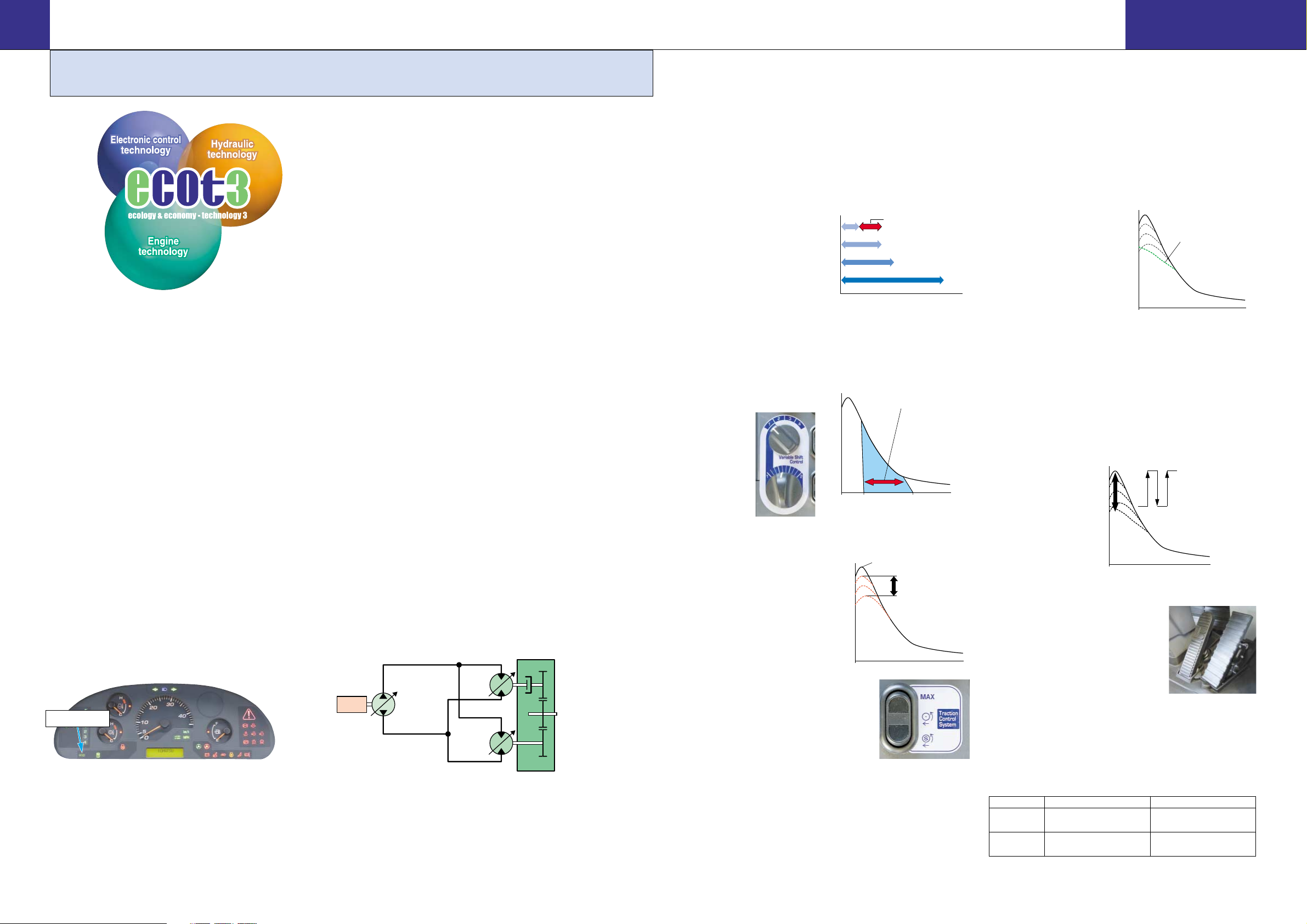
Electronically-Controlled HST with Variable Shift
Control System
The operator can choose between first, second, third or fourth
maximum speeds by dialing the speed range selector switch.
For v-cycles, the operator can set the speed control switch to
1 or 2, which provides
aggressive digging, quick
response and fast
hydraulics. For load and
carry, select 3 or 4 which
still provides aggressive
digging but with much
faster travel speed.
The variable shift switch allows the operator to adjust his
machine speed in applications such as confined v-loading.
When in 1, the operator can adjust travel speed using the
variable shift switch to match machine speed and hydraulics
to the distance travelled.
Variable Traction Control System
The tractive effort of the
machine, when traveling at a
low speed, can be reduced by
using the traction control
switch. Combined with the
function of torque
proportioning differentials, this
system exerts the following
effects.
● Facilitates operation on soft ground
where the tires of the machine are apt
to slip.
● Eliminates excessive bucket
penetration and reduces tire slippage
during stockpile loading to improve the work efficiency.
● Reduces tire slippage to extend the life of tires.
Furthermore, the maximum tractive effort can be adjusted in
three stages (one stage for conventional machines) when the
traction control switch is ON. This allows the operator to select
the optimum tractive effort for diversified road conditions.
S-mode
Setting the switch to S-mode allows the machine to get the
optimum driving force for operations on slippery road
surfaces, like snow-removal on snow surface, resulting in
reduced tire slippage and facilitation of the operation.
Unexpected tire slippage
on slippery road surface is
suppressed by controlling
the engine speed and HST
motor when traveling at a
low speed.
(S-mode is effective only in
forward traveling.)
High Performance Engine
Electronic Heavy Duty Common Rail fuel injection system
provides optimum combustion of fuel.
This system also provides fast throttle response to match the
machine’s powerful tractive effort and fast hydraulic response.
WA200PZ-6 SAA4D107E-1 Engine
Net: 94 kW 126 HP
WA250PZ-6 SAA6D107E-1 Engine
Net: 103 kW 138 HP
Low Emission Engine
This engine is EPA Tier 3 emission regulations and EU Stage
3A emission regulations certified, without sacrificing power or
machine productivity.
Low Fuel Consumption
The high-torque engine and Hydrostatic Transmission (HST)
with maximum efficiency in the low-speed range provide low
fuel consumption.
Eco Indicator
The eco indicator will help an operator to promote energy
saving.
Electronically-Controlled HST Using a 1-Pump,
2-Motor System
● The 1-pump, 2-motor system allows for high-efficiency
and high tractive effort. Engine power is transmitted
hydraulically to a transfer case, then manually out to the
differentials and out to the four driving wheels.
● HST provides quick travel response and aggressive drive
into the pile. The variable displacement system
automatically adjusts to the tractive effort demand to
provide maximum power and efficiency.
● Full auto-shifting eliminates any gear shifting and kickdown operation to allow the operator to concentrate on
digging and loading.
● When high drive torque is needed for digging, climbing or
initiating movement, the pump feeds both motors. This
combination makes the loader very aggressive and quick.
● Under deceleration, the HST system acts as a dynamic
brake on the mechanical drive system. The dynamic
brake can hold the loader in position on most workable
slopes. This can be an advantage in stockpiling and ramp
loading.
● As the machine moves and gains ground speed, the
torque demand decreases and the low speed motor is
effectively removed from the drive system by a clutch. At
this point, the flow is going to the high-speed motor and
the low-speed motor is not causing a drag on the
system.
● An inching pedal gives the operator excellent
simultaneous control of his travel and equipment
hydraulic speeds. By depressing the inching pedal, drive
pump flow to the motors will decrease, reducing ground
speed and allowing the operator to use his accelerator to
increase flow to his equipment hydraulics. Depressing
the inching pedal further will activate the service brakes.
Eco indicator
WA380-6
H
IGH
P
RODUCTIVITY AND
L
OW
F
UEL
C
ONSUMPTION
WA200PZ-6
WA250PZ-6
WHEEL LOADER
WITH PARALLEL Z BAR LINKAGE
WA200PZ-6/WA250PZ-6
W HEEL L
OADER WITH P ARALLEL Z BAR L INKAGE
Accelerator Pedal Sensitive HST
Control
Finely-tuned HST control according to
the accelerator pedal angle reduces
shocks and allows smoother traveling
and better energy-saving operation.
Max. Traction Switch
Max. traction switch is located on the work equipment control
lever. When traction control switch is at ON position or Smode is selected, pushing this switch cancels the setting of
the traction control temporarily and increases the tractive
effort to its 100 % value. Then pushing the max. traction
switch again or operating the F/R lever returns the tractive
effort to the set value
automatically. This
switch is useful for
operations such as
piling up work where
large tractive effort is
required temporarily.
WA200PZ-6 WA250PZ-6
Dumping
2810 mm 9'3" 2820 mm 9'3"
Clearance
Dumping 1090 mm 3'7" 1090 mm 3'7"
Reach
(2.0 m32.6 yd3bucket with B.O.C.) (2.2 m32.9 yd3bucket with B.O.C.)
Transfer case
Low speed
piston
motor
Engine
Piston Pump
High speed
piston
motor
To differentials
1st
2nd
3rd
4th
0
Tractive effort
0
Adjust the machine speed using
the Variable shift control system
4km/h
13km/h
13km/h
20km/h
Variable range of travel speed
4
Travel speed
13
34.5km/h
(km/h)
Max: Traction control switch is OFF.
(Max. tractive effort)
Max. tractive effort
can be adjusted in
3 stages when the
traction control
switch is ON.
Tractive effort
0
Travel speed
Tractive effort
0
S-mode:
Reduces the tractive effort
when traveling at a low speed
Travel speed
(i)
Tractive effort
0
Travel speed
Maximum tractive effort
(100% tractive effort)
(i)
(ii)
Set tractive effort
(When traction control is
"ON" or "S-mode" is selected)
Tractive effort changes between
(i) and (ii) each time the max. traction
switch is pushed.
Tractive effort returns to the set value
when the F/R lever is operated.

76
Komatsu Components
Komatsu manufactures the engine, transfer case, axles and
hydraulic components on
this wheel loader.
Komatsu loaders are
manufactured with an
integrated production
system under a strict
quality control system.
Wet multi-disc brakes and fully hydraulic braking
system mean lower maintenance costs and higher
reliability. Wet disc brakes are fully sealed. Contaminants
are kept out, reducing wear and resulting maintenance.
Brakes require no adjustments for wear, meaning even
lower maintenance. The parking brake is also an
adjustment-free, wet multi-disc for high reliability
and long life.
Added reliability is designed into the braking system by the
use of two independent hydraulic circuits, providing hydraulic
backup should one of the circuits fail.
Fully hydraulic brakes mean no air system to bleed,
and no condensation of water in the system that can
lead to contamination, corrosion, and freezing.
EMMS
(Equipment Management Monitoring System)
Monitor is mounted in front of the operator for
easy view, allowing the operator
to easily check gauges and
warning lights.
A specially designed two-spoke steering wheel allows the
operator to easily see the instrument panel.
Maintenance Control
and Troubleshooting Functions
● Action code display function: If an abnormality occurs,
the monitor displays action details on the character
display at the center bottom of the monitor.
● Monitor function: Controller monitors engine oil pressure,
coolant temperature, air cleaner clogging, etc.
If the controller finds abnormalities, the error is displayed
on the LCD.
● Replacement time notice function: Monitor informs
replacement time of oil and filters on the LCD when
replacement intervals are reached.
● Trouble data memory function: Monitor stores
abnormalities for effective troubleshooting.
Ease of Radiator Cleaning
If the machine is operating in adverse conditions, the
operator can reverse the hydraulic cooling fan from inside the
cab by turning on a switch on the control panel.
Overrun Prevention System
When the machine descends a slope of six degrees or less,
maximum travel speed is automatically restricted to
approximately 38 km/h 23 MPH, for protection against
damage of power train components and brakes by sensing
the travel speed and controlling the discharge amount of the
HST pump and motor. When the machine descends a steep
slope and the travel speed reaches
36 km/h 22 MPH, the caution lamp lights up to inform the
operator to reduce the travel speed.
Note: When the machine descends a steep slope, the use of
the service brake is necessary to limit travel speed.
Gull-wing Type Engine Side Doors Open Wide
The operator can open and close each gull-wing type engine
side door easily with the assistance of a gas spring to
perform daily service checks from the ground.
Automatic Reversible Fan (option)
The engine fan is driven hydraulically. It can be operated in
reverse automatically. When switch is automatic position.
The fan revolves in reverse for 2 minutes every 2 hours
intermittently. (Default setting)
High-rigidity Frames and Loader Linkage
The front and rear frames and the loader linkage have got
more torsional rigidity to provide resistance increased to
stresses. Frame and loader linkage are designed to
accommodate actual working loads,
and simulated computer
testing proves its strength.
Flat Face-to-Face O-Ring Seals
Flat face-to-face O-ring seals
are used to securely seal
hydraulic hose connections.
Cathion Electrodeposition Primer Paint/
Powder Coating Final Paint
Cathion electrodeposition paint is applied as a primer
paint and powder coating is applied as topcoat to the
exterior metal sheet parts. Some external parts are made of
plastic providing long life and high impact resistance.
Sealed DT Connectors
Main harnesses and controller connectors are equipped
with sealed DT connectors
providing high reliability, water
resistance and dust resistance.
nipple
hose
O-ring
WA380-6
I
NCREASED
R
ELIABILITY
WA200PZ-6
WA250PZ-6
WHEEL LOADER
WITH PARALLEL Z BAR LINKAGE
WA200PZ-6/WA250PZ-6
W HEEL L
OADER WITH P ARALLEL Z BAR L INKAGE
E
ASY
M
AINTENANCE
Photo may include optional equipment.
B: Manual Reverse Mode
A: Normal rotation Mode
C: Auto Reverse Mode
Front axle Rear axle
Engine
Transfer case

Pillar-less Large Cab
A wide pillar-less flat
glass provides excellent
front visibility. The wiper
arm covers a large area
to provide great visibility
even on rainy days.
The large cab area
provides maximum space for the operator. The front mounted
air conditioner was introduced to increase seat reclining and
backward slide adjustment.
Rear-hinged Full Open Cab Doors
Entry and exit into the new komatsu cab starts with sloped
staircase type steps and
large diameter handrails for
added comfort. The large
cab doors are rear-hinged
to open fully offering easy
entry/exit and will not
hamper visibility when
operating the machine with
the doors latched open.
8 9
Electronically Controlled Directional Lever
The operator can change direction with a touch of his fingers
without removing his
hand from the steering
wheel. Solid state
electronics makes this
possible.
Easy-to-operate Loader Control Mono-lever
A new mono-lever using PPC (Proportional Pressure Control)
allows the operator to easily operate the work equipment, to
reduce operator fatigue and
to increase controllability.
The adjustable wrist rest
provides the operator with
a variety of comfortable
operating positions.
Right-side control panel
The operator can select the speed range, maximum travel
speed in 1st, tractive effort.
Tiltable Steering Column
The operator can tilt the
steering column to provide
a comfortable working
position.
Easy Operation Comfortable Operation
Low-noise Design
Noise at operator’s ear noise level : 70 dB(A)
Dynamic noise level (outside): 104 dB(A)
The large cab is mounted with Komatsu’s
unique ROPS/FOPS viscous mounts. The
low-noise engine, hydraulically driven fan,
and hydraulic pumps are mounted with rubber cushions, and
the cab sealing is improved to provide a quiet,
low-vibration, pressurized, and comfortable operating
environment.
1
2
4
3
5
6 7
1:Speed range selector switch 2:Variable shift switch
3:Traction control switch 4:Max. traction switch
5:Fan reverse switch 6:Quick coupler lock switch
7:2 mode bucket leveler switch
Photo may include optional equipment.
WA380-6
O
PERATOR
E
NVIRONMENT
WA200PZ-6
WA250PZ-6
WHEEL LOADER
WITH PARALLEL Z BAR LINKAGE
WA200PZ-6/WA250PZ-6
W HEEL L
OADER WITH P ARALLEL Z BAR L INKAGE

10 11
WA380-6
WA380-6
S
PECIFICATIONS
WA200PZ-6
WA250PZ-6
WHEEL LOADER
WITH PARALLEL Z BAR LINKAGE
WA200PZ-6/WA250PZ-6
W HEEL L
OADER WITH P ARALLEL Z BAR L INKAGE
WA200PZ-6 WA250PZ-6
AXLES AND FINAL DRIVES
Drive system . . . . . . . . . . . . . . . . . . . . . . . . . . . . . .Four-wheel drive
Front . . . . . . . . . . . . . . . . . . . . . . . . . . . . . . . . . .Fixed, semi-floating
Rear . . . . . . . . . . . . . . . . . . . . . . .Center-pin support, semi-floating,
24˚ total oscillation
Reduction gear . . . . . . . . . . . . . . . . . . . . . . . . . . . .Spiral bevel gear
Differential gear . . . . . . . . . . . . . . . . . . . . . . . . .Torque proportioning
Final reduction gear . . . . . . . . . . . . .Planetary gear, single reduction
BRAKES
Service brakes . . . . . . . . . . . . . . . . . . . . . . . .Hydraulically actuated,
wet disc brakes actuate on four wheels
Parking brake . . . . . . . .Wet, multi-disc brake on transfer output shaft
Emergency brake . . . . . . . . . . . . . .Parking brake is commonly used
1st 2nd 3rd 4th
Both Forward 4.0 - 13.0 13.0 20.0 34.5
and Reverse 2.5 - 8.1 8.1 12.4 21.4
Measured with 20.5-25 tires
1st 2nd 3rd 4th
Both Forward 4.4 - 14.3 14.3 22.0 38.0
and Reverse 2.7 - 8.9 8.9 13.7 23.6
ENGINE
Model . . . . . . . . . . . . . . . . . . . . . . . . . . . . .Komatsu SAA4D107E-1
Type . . . . . . . . . . . . . . . . . . . . . . . . . . . . . . . .Water-cooled, 4-cycle
Aspiration . . . . . . . . . . . . . . . . . . . . . . . .Turbocharged, aftercooled
Number of cylinders . . . . . . . . . . . . . . . . . . . . . . . . . . . . . . . . . . . .4
Bore x stroke . . . . . . . . . . . . . . . . .107 mm x 124 mm 4.21" x 4.88"
Piston displacement . . . . . . . . . . . . . . . . . . . . . . . . .4.46 ltr 272 in
3
Governor . . . . . . . . . . . . . . . . . . . . . . . . . . . . . All-speed, electronic
Horsepower
SAE J1995 . . . . . . . . . . . . . . . . . . . . . . . . .Gross 95.2 kW 128 HP
ISO 9249/SAE J1349* . . . . . . . . . . . . . . . . . . .Net 94 kW 126 HP
Rated rpm . . . . . . . . . . . . . . . . . . . . . . . . . . . . . . . . . . . .2000 rpm
Fan drive method for radiator cooling . . . . . . . . . . . . . . . . .Hydraulic
Fuel system . . . . . . . . . . . . . . . . . . . . . . . . . . . . . . . .Direct injection
Lubrication system:
Method . . . . . . . . . . . . . . . . . . . . . . . .Gear pump, force-lubrication
Filter . . . . . . . . . . . . . . . . . . . . . . . . . . . . . . . . . . . . . Full-flow type
Air cleaner . . . . . . . . . . . . . . . . . .Dry type with double elements and
dust evacuator, plus dust indicator
*Net horsepower at the maximum speed of radiator cooling fan
is 91 kW 122 HP.
TRANSMISSION
Transmission:
Type . . . . . . .Hydrostatic, 1 pump, 2 motors with speed range select
Travel speed: km/h mph
Measured with 17.5-25 tires
STEERING SYSTEM
Type . . . . . . . . . . . . . . . . . . . . . . . . . . .Full-hydraulic power steering
Steering angle . . . . . . . . . . . . . . . .38˚ each direction (40˚ end stop)
Minimum turning radius at
the center of outside tire . . . . . . . . . . . . . . . . . . . . . .5100 mm 16'9"
HYDRAULIC SYSTEM
Steering system:
Hydraulic pump . . . . . . . . . . . . . . . . . . . . . . . . . . .Gear type pump
Capacity . . . . . . . . . . . . .85 ltr/min 22.5 U.S. gal/min at rated rpm
Relief valve setting . . . . . . . . . . . .20.6 MPa 210 kgf/cm23,000 psi
Hydraulic cylinders:
Type . . . . . . . . . . . . . . . . . . . . . . . . . .Double-acting, piston type
Number of cylinders . . . . . . . . . . . . . . . . . . . . . . . . . . . . . . . . . .2
Bore x stroke . . . . . . . . . . . . . . .70 mm x 453 mm 2.8" x 17.8"
Loader control:
Hydraulic pump . . . . . . . . . . . . . . . . . . . . . . . . . . .Gear type pump
Capacity . . . . . . . . . . . . . . . . . . . . . . .54 ltr/min 14.3 U.S. gal/min
Relief valve setting . . . . . . . . . . . .20.6 MPa 210 kgf/cm23,000 psi
Hydraulic cylinders:
Type . . . . . . . . . . . . . . . . . . . . . . . . . .Double-acting, piston type
Number of cylinders—bore x stroke:
Boom cylinder . . . . . . . . . .2- 120 mm x 673.5 mm 4.7" x 26.5"
Bucket cylinder . . . . . . . . . . .1- 130 mm x 493 mm 5.1" x 19.4"
Control valve . . . . . . . . . . . . . . . . . . . . . . . . . . . . . . . .3-spool type
Control positions:
Boom . . . . . . . . . . . . . . . . . . . . . . . .Raise, hold, lower, and float
Bucket . . . . . . . . . . . . . . . . . . . . . . . . .Tilt-back, hold, and dump
Hydraulic cycle time (rated load in bucket)
Raise . . . . . . . . . . . . . . . . . . . . . . . . . . . . . . . . . . . . . . . .5.7 sec
Dump . . . . . . . . . . . . . . . . . . . . . . . . . . . . . . . . . . . . . . . .1.6 sec
Lower (Empty) . . . . . . . . . . . . . . . . . . . . . . . . . . . . . . . . .3.2 sec
SERVICE REFILL CAPACITIES
Cooling system . . . . . . . . . . . . . . . . . . . . . . . .17.0 ltr 4.5 U.S. gal
Fuel tank . . . . . . . . . . . . . . . . . . . . . . . . . . . . .177 ltr 46.8 U.S. gal
Engine . . . . . . . . . . . . . . . . . . . . . . . . . . . . . .15.5 ltr 4.1 U.S. gal
Hydraulic system . . . . . . . . . . . . . . . . . . . . . . . .58 ltr 15.3 U.S. gal
Axle (each front and rear) . . . . . . . . . . . . . . . .18.0 ltr 4.8 U.S. gal
Torque converter and transmission . . . . . . . . . .5.0 ltr 1.3 U.S. gal
AXLES AND FINAL DRIVES
Drive system . . . . . . . . . . . . . . . . . . . . . . . . . . . . . .Four-wheel drive
Front . . . . . . . . . . . . . . . . . . . . . . . . . . . . . . . . . .Fixed, semi-floating
Rear . . . . . . . . . . . . . . . . . . . . . . .Center-pin support, semi-floating,
24˚ total oscillation
Reduction gear . . . . . . . . . . . . . . . . . . . . . . . . . . . .Spiral bevel gear
Differential gear . . . . . . . . . . . . . . . . . . . . . . . . .Torque proportioning
Final reduction gear . . . . . . . . . . . . .Planetary gear, single reduction
BRAKES
Service brakes . . . . . . . . . . . . . . . . . . . . . . . .Hydraulically actuated,
wet disc brakes actuate on four wheels
Parking brake . . . . . . . .Wet, multi-disc brake on transfer output shaft
Emergency brake . . . . . . . . . . . . . .Parking brake is commonly used
1st 2nd 3rd 4th
Both Forward 3.6 - 11.7 11.7 16.2 34.2
and Reverse 2.2 - 7.3 7.3 10.1 21.2
Measured with 20.5-25 tires
1st 2nd 3rd 4th
Both Forward 4.0 - 13.0 13.0 18.0 38.0
and Reverse 2.5 - 8.1 8.1 11.2 23.6
ENGINE
Model . . . . . . . . . . . . . . . . . . . . . . . . . . . . .Komatsu SAA6D107E-1
Type . . . . . . . . . . . . . . . . . . . . . . . . . . . . . . . .Water-cooled, 4-cycle
Aspiration . . . . . . . . . . . . . . . . . . . . . . . .Turbocharged, aftercooled
Number of cylinders . . . . . . . . . . . . . . . . . . . . . . . . . . . . . . . . . . . .6
Bore x stroke . . . . . . . . . . . . . . . . .107 mm x 124 mm 4.21" x 4.88"
Piston displacement . . . . . . . . . . . . . . . . . . . . . . . . .6.69 ltr 408 in
3
Governor . . . . . . . . . . . . . . . . . . . . . . . . . . . . . All-speed, electronic
Horsepower
SAE J1995 . . . . . . . . . . . . . . . . . . . . . . . . .Gross 104 kW 140 HP
ISO 9249/SAE J1349* . . . . . . . . . . . . . . . . . .Net 103 kW 138 HP
Rated rpm . . . . . . . . . . . . . . . . . . . . . . . . . . . . . . . . . . . .2000 rpm
Fan drive method for radiator cooling . . . . . . . . . . . . . . . . .Hydraulic
Fuel system . . . . . . . . . . . . . . . . . . . . . . . . . . . . . . . .Direct injection
Lubrication system:
Method . . . . . . . . . . . . . . . . . . . . . . . .Gear pump, force-lubrication
Filter . . . . . . . . . . . . . . . . . . . . . . . . . . . . . . . . . . . . . Full-flow type
Air cleaner . . . . . . . . . . . . . . . . . .Dry type with double elements and
dust evacuator, plus dust indicator
*Net horsepower at the maximum speed of radiator cooling fan
is 100 kW 134 HP.
TRANSMISSION
Transmission:
Type . . . . . . .Hydrostatic, 1 pump, 2 motors with speed range select
Travel speed: km/h mph
Measured with 17.5-25 tires
STEERING SYSTEM
Type . . . . . . . . . . . . . . . . . . . . . . . . . . .Full-hydraulic power steering
Steering angle . . . . . . . . . . . . . . . .38˚ each direction (40˚ end stop)
Minimum turning radius at
the center of outside tire . . . . . . . . . . . . . . . . . . . . . .5175 mm 17'0"
HYDRAULIC SYSTEM
Steering system:
Hydraulic pump . . . . . . . . . . . . . . . . . . . . . . . . . . .Gear type pump
Capacity . . . . . . . . . . . .110 ltr/min 29.1 U.S. gal/min at rated rpm
Relief valve setting . . . . . . . . . . . .18.6 MPa 190 kgf/cm22,700 psi
Hydraulic cylinders:
Type . . . . . . . . . . . . . . . . . . . . . . . . . .Double-acting, piston type
Number of cylinders . . . . . . . . . . . . . . . . . . . . . . . . . . . . . . . . . .2
Bore x stroke . . . . . . . . . . . . . . .70 mm x 453 mm 2.8" x 17.8"
Loader control:
Hydraulic pump . . . . . . . . . . . . . . . . . . . . . . . . . . .Gear type pump
Capacity . . . . . . . . . . . . . . . . . . . . . . .78 ltr/min 20.6 U.S. gal/min
Relief valve setting . . . . . . . . . . . .20.6 MPa 210 kgf/cm23,000 psi
Hydraulic cylinders:
Type . . . . . . . . . . . . . . . . . . . . . . . . . .Double-acting, piston type
Number of cylinders—bore x stroke:
Boom cylinder . . . . . . . . . . .2- 130 mm x 717 mm 5.1" x 28.2"
Bucket cylinder . . . . . . . . . . .1- 150 mm x 491 mm 5.9" x 19.3"
Control valve . . . . . . . . . . . . . . . . . . . . . . . . . . . . . . . .3-spool type
Control positions:
Boom . . . . . . . . . . . . . . . . . . . . . . . .Raise, hold, lower, and float
Bucket . . . . . . . . . . . . . . . . . . . . . . . . .Tilt-back, hold, and dump
Hydraulic cycle time (rated load in bucket)
Raise . . . . . . . . . . . . . . . . . . . . . . . . . . . . . . . . . . . . . . . .5.7 sec
Dump . . . . . . . . . . . . . . . . . . . . . . . . . . . . . . . . . . . . . . . .1.6 sec
Lower (Empty) . . . . . . . . . . . . . . . . . . . . . . . . . . . . . . . . .3.3 sec
SERVICE REFILL CAPACITIES
Cooling system . . . . . . . . . . . . . . . . . . . . . . . . .22 ltr 5.8 U.S. gal
Fuel tank . . . . . . . . . . . . . . . . . . . . . . . . . . . . .186 ltr 49.1 U.S. gal
Engine . . . . . . . . . . . . . . . . . . . . . . . . . . . . . . . .23 ltr 6.1 U.S. gal
Hydraulic system . . . . . . . . . . . . . . . . . . . . . . . .67 ltr 17.7 U.S. gal
Axle (each front and rear) . . . . . . . . . . . . . . . . .18 ltr 4.8 U.S. gal
Torque converter and transmission . . . . . . . . . . .5 ltr 1.3 U.S. gal

12 13
WA380-6
WA380-6
WA200PZ-6
WA250PZ-6
WHEEL LOADER
WITH PARALLEL Z BAR LINKAGE
WA200PZ-6/WA250PZ-6
W HEEL L
OADER WITH P ARALLEL Z BAR L INKAGE
Model WA200PZ-6 WA250PZ-6
Tires 17.5-25 20.5-25 17.5-25 20.5-25
Tread 1930 6'4" 1930 6'4" 1930 6'4" 1930 6'4"
Width over tires 2375 7'10" 2470 8'1" 2375 7'10" 2470 8'1"
A Wheelbase 2840 9'4" 2840 9'4" 2900 9'6" 2900 9'6"
B Hinge pin height , max. height 3815 12'6" 3885 12'9" 3895 12'9" 3965 13'0"
C Ground clearance 425 1'5" 495 1'8" 395 1'4" 465 1'6"
D Hitch height 870 2'10" 940 3'1" 880 2'11" 950 3'1"
E Overall height, top of stack 2725 8'11" 2795 9'2" 2855 9'4" 2925 9'7"
F Overall height, ROPS cab 3110 10'2" 3180 10'5" 3130 10'3" 3200 10'6"
Model WA200PZ-6 WA250PZ-6
Tires (Measured with) 20.5-25-12PR(L2) 20.5-25-12PR(L2)
Bucket Stockpile Bucket With Bolt-On Cutting Edge Stockpile Bucket With Bolt-On Cutting Edge
Bucket Capacity
Heaped 2.0 m
3
2.6 yd
3
2.2 m
3
2.9 yd
3
Struck 1.7 m
3
2.2 yd
3
2.1 m
3
2.7 yd
3
Bucket Width 2540 mm 8'4" 2550 mm 8'4"
Static Tipping Load
Straight 8110 kg 17,880 lb 9090 kg 20,040 lb
Full Turn (40˚) 7040 kg 15,520 lb 7940 kg 17,500 lb
Operating Weight 11450 kg 25,240 lb 12690 kg 27,980 lb
Bucket Weight 910 kg 2,005 lb 960 kg 2,120 lb
G Dumping Clearance, maximum
height and 45˚ dump angle* 2810 mm 9'3" 2820 mm 9'3"
Reach at 2130 mm 7'
and 45˚ dump angle* 1645 mm 5'5" 1650 mm 5'5"
H Reach at maximum height
and 45˚ dump angle* 1090 mm 3'7" 1090 mm 3'7"
Reach with boom/bucket level* 3275 mm 10'9" 3330 mm 10'11"
I Operating Height, fully raised 5305 mm 17'5" 5365 mm 17'7"
J Overall Length, bucket on ground 7310 mm 24'0" 7410 mm 24'4"
Digging Depth
0˚ 120 mm 4.7" 142 mm 5.6"
10˚ 345 mm 1'2" 375 mm 1'3"
Breakout Force 9010 kg 19,865 lb 10730 kg 23,660 lb
*At the end of B.O.C.
All dimensions, weights, and performance values based on SAE J732c and J742b standards. Static tipping load and operating weight shown include lubricant,
coolant, full fuel tank, ROPS cab and operator. Machine stability and operating weight affected by tire size and attachments.
Weight Changes
WA200PZ-6
WA250PZ-6
Change in
Change in Tipping Load
Width Ground Change in Change in
Operating Weight Straight Full Turn Over Tires Clearance
Vertical Dimensions
Reach
17.5-25-12PR (L2) –325 kg –716 lb –215 kg –474 lb –185 kg –408 lb 2375 mm 7'10" 425 mm 1'5" –70 mm –2.8" 75 mm 3.0"
17.5-25-12PR (L3) –290 kg –639 lb –190 kg –419 lb –167 kg –368 lb 2375 mm 7'10" 425 mm 1'5" –70 mm –2.8" 75 mm 3.0"
20.5-25-12PR (L3) 165 kg 364 lb 105 kg 231 lb 95 kg 209 lb 2470 mm 8'1" 495 mm 1'8" 0 mm 0" 0 mm 0"
Install ROPS canopy (instead of cab) –167 kg –368 lb –152 kg –335 lb –134 kg –295 lb
DIMENSIONS
A
J
H
F
E
D
45
C
G
B
I
BUCKET SELECTION GUIDE
Material (loose weight) kg/m
3
lb/yd
3
Caliche 1250 2,100
Cinders 590 1,000
Clay and gravel, dry 1420 2,400
Clay and gravel, wet 1540 2,600
Clay, dry 1480 2,500
Clay, natural bed 1660 2,800
Clay, wet 1660 2,800
Coal, anthracite, broken 1100 1,850
Coal, bituminous, broken 830 1,400
Earth, dry, packed 1510 2,550
Earth, loam 1250 2,100
Earth, wet, excavated 1600 2,700
Granite, broken or large crushed 1660 2,800
Gravel, dry 1510 2,550
Gravel, dry 13 to 50 mm 1/2" to 2" 1690 2,850
Gravel, pit run (graveled sand) 1930 3,250
Gravel, wet 13 to 50 mm 1/2" to 2" 2020 3,400
Gypsum, crushed 1600 2,700
Limestone, broken or crushed 1540 2,600
Magnetite, iron ore 2790 4,700
Phosphate rock 1280 2,160
Pyrite, iron ore 2580 4,350
Sand and gravel, dry 1720 2,900
Sand and gravel, wet 2020 3,400
Sand, dry 1420 2,400
Sand, wet 1840 3,100
Sandstone, broken 1510 2,550
Shale 1250 2,100
Slag, broken 1750 2,950
Stone, crushed 1600 2,700
Topsoil 950 1,600
This guide, representing bucket sizes not necessarily
manufactured by Komatsu, will help you select the proper
bucket size for material density, loader configuration, and
operating conditions. Optimum bucket size is determined
after adding or subtracting all tipping load changes due
to optional equipment. Bucket fill factors represent the
approximate amount of material as a percent of rated
bucket capacity. Fill factors are primarily affected by
material, ground conditions, breakout force, bucket profile,
and the cutting edge of the bucket used.
Change in
Change in Tipping Load
Width Ground Change in Change in
Operating Weight Straight Full Turn Over Tires Clearance
Vertical Dimensions
Reach
17.5-25-16PR (L2) –300 kg –661 lb –200 kg –441 lb –170 kg –375 lb 2375 mm 7'10" 395 mm 1'4" –70 mm –2.8" 70 mm 2.8"
17.5-25-16PR (L3) –260 kg –573 lb –170 kg –375 lb –150 kg –331 lb 2375 mm 7'10" 395 mm 1'4" –70 mm –2.8" 70 mm 2.8"
20.5-25-12PR (L3) 165 kg 364 lb 110 kg 243 lb 95 kg 209 lb 2470 mm 8'1" 465 mm 1'6" 0 mm 0" 0 mm 0"
Install ROPS canopy (instead of cab) –165 kg –364 lb –145 kg –320 lb –125 kg –276 lb
Bucket
mm ft.in
WA200PZ-6
1
0
5
%
2.6
3.4
3
yd
3
2.2
2.9
2.4
1.8
Bucket capacity: m
1.4
1.8
1.3
1.0
B
2.0 m3 2.6 yd3
Stockpile Bucket
1686 2192 2698 3203 3709
1000 1300 1600 1900 2200
WA250PZ-6
1
0
5
%
2.8
3.7
3
yd
3
2.4
3.1
2.6
2.0
Bucket capacity: m
1.6
2.1
1.6
1.2
B
2.2 m3 2.9 yd3
Stockpile Bucket
1686 2192 2698 3203 3709
1000 1300 1600 1900 2200
1
9
0
5
0
%
%
B
B
u
u
u
c
k
e
u
c
k
Material density: kg/m
c
c
k
k
e
e
t
t
t
F
i
l
l
Material density: kg/m
1
0
0
%
e
t
F
i
l
l
F
F
i
l
l
i
l
l
9
5
%
B
B
u
c
u
k
c
e
k
t
e
F
t
i
F
l
l
i
l
l
3
lb/yd
3
lb/yd
3
3

14 15
WA380-6
WA380-6
WA200PZ-6
WA250PZ-6
WHEEL LOADER
WITH PARALLEL Z BAR LINKAGE
WA200PZ-6/WA250PZ-6
W HEEL L
OADER WITH P ARALLEL Z BAR L INKAGE
Operating load per SAE J1197 (Feb. 1991), 50% of static tipping load.
Static tipping load and operating weight shown include lubricant, coolant, full fuel tank, ROPS cab and operator. Machine stability and operating weight affected
by tire size and attachments.
Weight Changes
WA200PZ-6
WA250PZ-6
DIMENSIONS
STANDARD EQUIPMENT
● 3-spool valve for boom and bucket
controls
● Additional counterweight
● Air conditioner
● Alternator, 60 A
● Auto shift transmission with mode
select system
● Back-up alarm
● Back-up lamp
● Batteries, 88 Ah/2 x 12 V
● Bucket positioner
● Counterweight
● Directional signal
● Engine, Komatsu SAA4D107E-1 diesel
● Engine shut-off system, electric
● Floor mat
● Fuel prefilter with water separator
● Hydraulic-driven fan with reverse rotation
● Lift cylinders and bucket cylinder
● Loader linkage with PZ lift arm
● Main monitor panel with
EMMS (Equipment Management
Monitoring System)
● PPC fingertip control, mono lever +1
● Quick coupler
● Radiator mask, lattice type
● Rear defroster (electric)
● Rear view mirror
● Rear window washer and wiper
● ROPS/FOPS cab
● Seat, rigid type with reclining
● Seat belt
● Service brakes, wet disc type
● Starting motor, 4.5 kW/24 V
● Steering wheel, tiltable
● Sun visor
● Tires (20.5-25-12PR, L2 tubeless)
and rims
● Transmission, 4 forward and 4 reverse
● Bucket, stockpile, for use with coupler
with B.O.C. 2.0 m32.6 yd
3
● 3-spool valve for boom and bucket
controls
● Additional counterweight
● Air conditioner
● Alternator, 60 A
● Auto shift transmission with mode
select system
● Back-up alarm
● Back-up lamp
● Batteries, 110 Ah/2 x 12 V
● Bucket positioner
● Counterweight
● Directional signal
● Engine, Komatsu SAA6D107E-1 diesel
● Engine shut-off system, electric
● Floor mat
● Fuel prefilter with water separator
● Hydraulic-driven fan with reverse rotation
● Lift cylinders and bucket cylinder
● Loader linkage with PZ lift arm
● Main monitor panel with
EMMS (Equipment Management
Monitoring System)
● PPC fingertip control, mono lever +1
● Quick coupler
● Radiator mask, lattice type
● Rear defroster (electric)
● Rear view mirror
● Rear window washer and wiper
● ROPS/FOPS cab
● Seat, rigid type with reclining
● Seat belt
● Service brakes, wet disc type
● Starting motor, 4.5 kW/24 V
● Steering wheel, tiltable
● Sun visor
● Tires (20.5-25-16PR, L2 tubeless)
and rims
● Transmission, 4 forward and 4 reverse
● Bucket, stockpile, for use with coupler
with B.O.C. 2.2 m32.9 yd
3
WA200PZ-6
WA250PZ-6
Change in
Change in Tipping Load
Width Ground Change in Change in
Operating Weight Straight Full Turn Over Tires Clearance
Vertical Dimensions
Reach
17.5-25-12PR(L2) –325 kg –716 lb –215 kg –474 lb –185 kg –408 lb 2375 mm 7'10" 425 mm 1'5" –70 mm –2.8" 75 mm 3.0"
17.5-25-12PR(L3) –290 kg –639 lb –190 kg –419 lb –167 kg –368 lb 2375 mm 7'10" 425 mm 1'5" –70 mm –2.8" 75 mm 3.0"
20.5-25-12PR(L3) 165 kg 364 lb 105 kg 231 lb 95 kg 209 lb 2470 mm 8'1" 495 mm 1'8" 0 mm 0" 0 mm 0"
Install ROPS canopy (instead of cab) –167 kg –368 lb –152 kg –335 lb –134 kg –295 lb
Model WA200PZ-6 WA250PZ-6
Tires (Measured with) 20.5-25-12PR(L2) 20.5-25-12PR(L2)
Static tipping load – boom level
Fork level, 610 mm 24"
load center Straight 6050 kg 13,340 lb 6875 kg 15,160 lb
Full turn (40˚) 5300 kg 11,680 lb 5980 kg 13,180 lb
Operating weight 11460 kg 25,260 lb 12275 kg 27,060 lb
G Fork tine length 1200 mm 3'11" 1220 mm 4'0"
H Ground to top of tine
at maximum lift 3765 mm 12'4" 3820 mm 12'6"
I Reach at maximum lift 775 mm 2'7" 790 mm 2'7"
J Ground to top of Tine –
boom and tine level 1780 mm 5'10" 1820 mm 6'0"
K Reach – boom and tine level 1675 mm 5'6" 1690 mm 5'7"
L Reach – tine level on ground 1040 mm 3'5" 1025 mm 3'4"
M Overall Length – tine level on ground 7645 mm 25'1" 7680 mm 25'2"
Operating load 2650 kg 5,840 lb 2990 kg 6,590 lb
A
L
G
M
K
I
F
E
D
C
J
B
H
Change in
Change in Tipping Load
Width Ground Change in Change in
Operating Weight Straight Full Turn Over Tires Clearance
Vertical Dimensions
Reach
17.5-25-16PR(L2) –300 kg –661 lb –140 kg –309 lb –125 kg –276 lb 2375 mm 7'10" 395 mm 1'4" –70 mm –2.8" 70 mm 2.8"
17.5-25-16PR(L3) –260 kg –573 lb –125 kg –276 lb –110 kg –243 lb 2375 mm 7'10" 395 mm 1'4" –70 mm –2.8" 70 mm 2.8"
20.5-25-12PR(L3) 165 kg 364 lb 80 kg 176 lb 70 kg 154 lb 2470 mm 8'1" 465 mm 1'6" 0 mm 0" 0 mm 0"
Install ROPS canopy (instead of cab) –165 kg –364 lb –105 kg –231 lb –90 kg –198 lb
Fork
Model WA200PZ-6 WA250PZ-6
Tires 17.5-25 20.5-25 17.5-25 20.5-25
Tread 1930 6'4" 1930 6'4" 1930 6'4" 1930 6'4"
Width over tires 2375 7'10" 2470 8'1" 2375 7'10" 2470 8'1"
A Wheelbase 2840 9'4" 2840 9'4" 2900 9'6" 2900 9'6"
B Hinge pin height , max. height 3815 12'6" 3885 12'9" 3895 12'9" 3965 13'0"
C Ground clearance 425 1'5" 495 1'8" 395 1'4" 465 1'6"
D Hitch height 870 2'10" 940 3'1" 880 2'11" 950 3'1"
E Overall height, top of stack 2725 8'11" 2795 9'2" 2855 9'4" 2925 9'7"
F Overall height, ROPS cab 3110 10'2" 3180 10'5" 3130 10'3" 3200 10'6"
mm ft.in
Quick coupler
 Loading...