


Walk-In Unit
Installation & Operation
Manual
Manitowoc Foodservice Walk-In Division |
|
2915 Tennessee Avenue North |
|
P.O. Box 550 |
|
Parsons, TN 38363 |
|
Phone: 800-225-9916 |
500000400-1 |
www.manitowoc.com |
March 2011 |
www.manitowoc.com |
800-225-9916 |
1 |

Table of Contents
Safety Information .…………………..………………………………………. 3 Receiving Inspection ……………………………………………………. ….. 4 Panel Storage ………………………………………………….…………….. 4-5 Panel Identification ………………………………………..…………………. 5 Site Preparation ………………………………………………………………. 6 Cam Action Panel Fasteners…………………………………..……………. 7 General Installation Guidelines ………………………………………………… 7 Screed Identification …………………………………………………………. 8-9 Screed Installation ………………………………………………………… 10 Floor Panel Installation ….……………………………………………………… 11 Floor Overlay Installation ……………………………………………………… 12 Concrete & Tile Flooring ………………………………………………………. 12 Wall & Door Section Installation ……………………………………………….. 13 Ceiling Panel Installation ……………………………………………………….. 14 Split-Over Partition Wall/Ceiling …………………………………………….. 15 Ceiling Support ………… ……………………………………………………… 16 Interior/Exterior Ramps ………………………………………………………… 17 Plug Buttons & Penetrations ………………………………………………….. 18 Trim & Wainscoting Material ………………………………………………….. 19 Threshold Installation ………………………………………………………….. 20 Door Adjustment ………………………………………………………………... 21 Adjustable Hinges ………………………………………………………………. 22 Thermometer Testing & Recalibration ………………………………………... 23 Electrical Connections ………………………………………………………….. 24 Wiring Diagrams ………………………………………………………………… 25-31 Tapered Roof System ………………………………………………………….. 32 Membrane Roof System..……………………………………………………… 32-35 Maintenance & Housekeeping………………………………………………… 36 Warranty Information………….………………………………………………… 37
www.manitowoc.com |
800-225-9916 |
2 |

General Safety Information
Read this manual carefully before beginning the installation and operation of the unit. Special attention is required to all sections identified with the following warning and caution notices:
 WARNING
Text in a Warning box alerts you to a potential personal injury situation. Read each Warning statement before proceeding and work carefully.
 CAUTION
Text in a Caution box alerts you to a situation in which you could damage the unit. Read each Caution statement before proceeding and work carefully.
Disregarding these special notices may result in personal injury and/or damage to the unit.
Safety Notices:
Installation and maintenance/servicing are to be performed only by trained and qualified personnel familiar with commercial walk-in products.
Ensure that all field wiring conforms to the equipment requirements and all applicable local and national codes.
Disconnect all power sources before servicing the unit.
Sheet metal and coil surfaces have sharp edges. Use appropriate protective gloves to prevent injury.
Use appropriate eye protection during installation and servicing.
www.manitowoc.com |
800-225-9916 |
3 |

Receiving Inspection
Check the shipment carefully and compare to the bill of lading. Account for all items listed and inspect each container for damage. Carefully inspect for any concealed damage. Report any shortages or damages to the carrier, note on the bill of lading, and file a freight claim.
Damaged material cannot be returned to the manufacturer without prior approval. A Return Material Authorization (RMA) must be obtained. Contact a sales representative at 800-826-7036.
Panel Count and Hardware
Using the packing list and skid documentation, count the wall panels, corners, ceilings, doors, and floors where applicable. Locate and verify the accessory and hardware package(s).
 WARNING
Do not attempt to lift the panels or accessories by yourself. Always have adequate lifting equipment or manpower available to accomplish the task safely.
Do not unwrap the skids and leave the panels in a position that they could fall over or blow over and cause an injury. Be sure that panels are adequately restrained at all times.
 CAUTION
Make sure to store the panels as noted below if necessary to ensure that they are not damaged prior to being installed.
Panel Storage
If the walk-in panels must be stored on a job site before installation, store them inside if possible.
The panels may be stored on skids as received, provided the skids are on level surface and kept free of moisture.
If the panels must be stored outside, store them on edge with the grooved side (female rail) facing down. Kiln-dried wood spacers provide a ventilation gap to prevent moisture stains from forming on the panels’ metal skins. Cover the panels with black plastic to keep out sunlight and moisture. Be sure the plastic does not touch the ground, allowing air circulation.
www.manitowoc.com |
800-225-9916 |
4 |

Panel identification
Each panel is labeled to aid in identification and proper placement. Panel item numbers are referenced on the product assembly drawing showing proper location for intended installation within the unit.
www.manitowoc.com |
800-225-9916 |
5 |
Site Preparation
 CAUTION
Ensure that the area for installation is level and clear of all debris before beginning assembly. If care is not taken to assure a level base, wall and ceiling panels will not align properly, causing problems in installation and operation of door panels, and potential performance issues due to escessive air leaks.
A 1” minimum clearance is required between the unit and any adjacent structures to allow for wall surface irregularities and for air circulation. Failure to allow for this clearance may result in performance issues such as excesive moisture and/or condensation in the unit or adjoining areas.
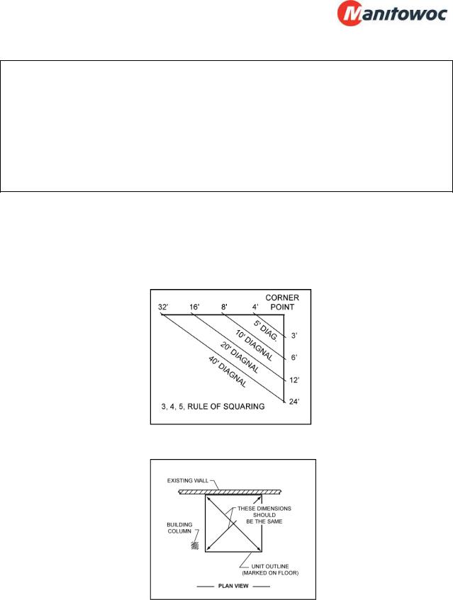
Using the supplied unit assembly drawing (packed in hardware box), mark the perimeter of screed, wall, or floor sections on the existing building floor using a chalk line
Perimeter lines must be square and parallel. Use the 3,4,5 rule of squaring as illustrated.
After establishing the first two lines, measure and establish the rest of the perimeter.
If the installation area is not level, find the high point of this perimeter line. The floor, floor screed and wall must be leveled to this point.
www.manitowoc.com |
800-225-9916 |
6 |

Cam Action Panel Fasteners
Before starting to assemble the unit, be sure to familiarize yourself with the operation of the panel fasteners
To operate the cam locks, insert a 5/16” hex wrench (packed in hardware box) through the access hole in the panel interior skin, and into the hex opening in the fastener. Turn the wrench clockwise approximately 3/4 of a complete turn, to put the cam hook into the locked position.
If a problem should occur, such as having to unlock a panel that was not properly positioned, you must turn the handle counterclockwise until it stops, in order to reset the cam position.
CAM |
3/4" TURN |
CAM |
|
PIN |
PIN |
|
|
 CAUTION
Using a hammer to drive the hex wrench into the panel fastener can result in damaging the interface surface, rendering the lock unusable. Clear the hole of any debris if the wrench cannot be fully inserted with normal hand pressure.
General Installation Guidelines
All insulated panels have a tongue and a groove perimeter edge. This interlocking design and the panel edge gaskets will result in an air-tight walk-in when installed square and level. Refer to the assembly drawing for the general layout and specific panel placement and markings.
The tongue side of the panel and cam lock holes is on the left of each seam when viewed from the interior of the walk-in (standing on the inside and looking out). The exact location of the tongue (M) and groove (F) for ceiling and floor panels, if required, will be shown on the assembly drawing.
www.manitowoc.com |
800-225-9916 |
7 |
Screed Identification
There are many styles of screeds used in walk-in coolers and freezers. The types of screeds furnished with your unit will be identified on the unit assembly drawing.
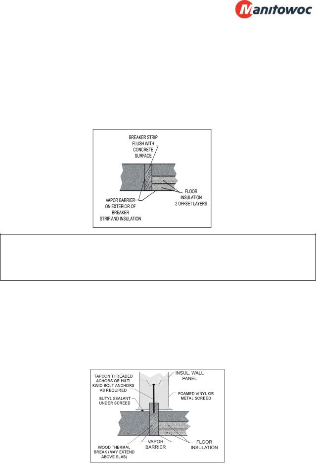
Breaker strips (thermal breaks) are used to prevent heat transfer between the cooled side and the ambient side of a concrete floor. Without these thermal barriers, heat transfer through the concrete layer is relatively rapid, causing a greater likelihood of condensation and icing outside of the unit, as well as increased energy consumption and cooling load on the refrigeration system.
 CAUTION
When having a product installed with a thermal break, make sure that the contractor leaves the top of the thermal break exposed for later inspection, not covered by concrete. If there are performance issues after instalation, it may be necessary to inspect the position and condition of the thermal break.
Standard screeds are available in both vinyl (with integral floor coves) and metal versions. Vinyl screeds cannot be used in outdoor applications due to potential issues with UV degradation caused by sunlight. Most thermal breaks are installed to be level with the concrete surface, but some thermal breaks protruding from the surface can be accommodated by vinyl screeds. Heights for vinyl screeds are 1.5” or 4”, while metal screeds are available in various heights as necessary for the application. Standard screeds are pre cut with intended installation locations shown on the assembly drawing.
www.manitowoc.com |
800-225-9916 |
8 |
U-shaped screeds are available for customers who desire to use a vinyl screed, but need either a lower profile or need a special height finished unit, and would prefer to use a standard sized wall panels. U-shaped screeds are factory cut to length and mitered on the corners, with intended installation locations shown on the assembly drawing.
Flat-bottom walls are available for configurations that require a metal screed, do not have an integral cove, and will be anchored by an exterior (or interior) mounting angle. Mounting angles are supplied in 10’ lengths and field cut to fit the dimensions of the enclosure as necessary.
www.manitowoc.com |
800-225-9916 |
9 |

Screed Installation
Place the screeds on the floor using the chalk lines as guides. Where factory cut screed is used, screed sizes and layout are identified in the assembly drawings.
A thermal break (breaker strip) is required to separate all freezer interior concrete from the exterior concrete. The interior freezer concrete floor must be insulated and completely isolated. The screed/wall is to be centered over the thermal break.
Apply a single bead of non-drying (Butyl) sealant under the screeds along the warm side (cooler side for partition walls, exterior side for perimeter walls).
Start at back corner and fasten screeds in place for two adjoining walls. Fasten screed as shown on assembly drawing with fasteners provided.
To insure proper fit, do not fasten screeds for remaining walls until the first two walls are assembled.
CAUTION
Thermal breaks are required in freezer applications and recommended in cooler applications to separate the interior flooring from the exterior floor. Thermal breaks prevent heat transfer and increase energy efficiency.
A 3/8” bead of non-drying (butyl) sealant is required on the warm side of all screed applications. The bead should be continuous around the complete perimeter of the walk-in. This sealant application will assist in maintaining the vapor barrier.
www.manitowoc.com |
800-225-9916 |
10 |
Floor Panel Installation
Review the floor panel layout on the assembly drawing. Panels are labeled with numbers corresponding to those on the assembly drawing.
 CAUTION
Stationary floor loads of up to 700 pounds per square foot can be stored on Manitowoc standard pre-fabricated floor panels. If mobile equipment is used (dollies, carts, etc.), the floor must be reinforced with an appropriate thickness of flooring overlay. If forklift trucks are used, special construction techniques must be followed for concrete wear surfaces over the panels. Consult customer service for recommendations.
Mark and level the floor according to site preparation requirements.
Lay out floor panels in correct sequence according to assembly drawings, making sure the flooring is level.
Lock floor panels together, making sure edges are flush and square.
www.manitowoc.com |
800-225-9916 |
11 |

Flooring Overlay Installation
 CAUTION
Installation of overlay material is best accomplished before the refrigeration system has been started, and before any product has been loaded. In the event that overlay must be added at a later date, ensure that the refrigeration system has been turned off and that the subsurface has been allowed to return to a normal working temperature. Installing at a low temperature may not allow the adhesive/sealant to cure adequately.
Clean and dry subsurface.
Apply silicone to the underside of flooring overlay material.
Begin laying first row of flooring overlay ½” away from the edge of the floor according to the drawing and secure to the subsurface with sheet metals screws or anchors.
All sheets must be as flush as possible to one another.
All sheets must be secured using a sheet metal screws or anchors every 24”. Ensure that at least one fastener is used near each corner of the overlay material.
Continue to follow the layout according to the drawing until all sheets are flush and secured to the subsurface.
Caulk all seams and edges of flooring overlay material.
Allow 1-3 hours for the adhesive/sealant to dry prior to resuming use of the walkin.
Concrete & Tile Flooring
 CAUTION
Gasses emitted by curing concrete floors or tile grout will damage panel finishes. Adequate ventilation must be provided when the concrete floor or tile setting bed and grout is curing. Leave all doors open for ventilation. If concrete or tile is to be installed after walk-in is erected, protect the wall finish by applying a protective covering.
www.manitowoc.com |
800-225-9916 |
12 |
 Loading...