


OWNER’S MANUAL
Installation, Operation & Maintenance Instructions
NOTE: Read this manual completely before attempting installation of your POLAR-PAK refrigeration system. Damage could occur to the unit if instructions are not followed completely.
Kol pak ... Spe ci fie d #1 Amo ng Walk -i ns ww w.k olp ak .co m
Table of Contents
RECEIVING INSPECTION ................................................................................................................................................ |
1 |
||
1.0 |
INSTALLATION – GENERAL INFORMATION .................................................................................................. |
1 |
|
2.0 |
INSTALLATION – TOP MOUNT MODELS ........................................................................................................... |
2 |
|
|
2.1 |
INSTALLING THE ROOF MEMBRANE AND CURB – OUTDOOR UNITS ONLY ..................................................... |
2 |
|
2.2 |
JOINING THE REFRIGERATION UNIT TO THE CEILING PANEL .............................................................................. |
3 |
|
2.3 |
WALK-IN ASSEMBLY........................................................................................................................................... |
4 |
3.0 |
POWER HOOK-UP – TOP MOUNT MODELS...................................................................................................... |
5 |
|
|
3.1 |
COOLERS ............................................................................................................................................................. |
5 |
|
3.2 |
FREEZERS ............................................................................................................................................................ |
6 |
4.0 |
INSTALLATION – SIDE MOUNT MODELS .......................................................................................................... |
7 |
|
|
4.1 |
PREPARATION FOR INSTALLATION....................................................................................................................... |
7 |
|
4.2 |
WALK-IN ASSEMBLY ........................................................................................................................................... |
7 |
|
4.3 |
MOUNTING THE REFRIGERATION UNIT................................................................................................................ |
8 |
5.0 |
POWER HOOK-UP – SIDE MOUNT MODELS .................................................................................................... |
10 |
|
|
5.1 |
COOLERS .......................................................................................................................................................... |
10 |
|
5.2 |
FREEZERS ......................................................................................................................................................... |
10 |
6.0 |
OPERATION .............................................................................................................................................................. |
13 |
|
|
6.1 |
COOLERS - ALL MODELS ................................................................................................................................... |
13 |
|
6.2 |
FREEZERS - ALL MODELS .................................................................................................................................. |
13 |
7.0 |
DEFROST CYCLE .................................................................................................................................................... |
13 |
|
|
7.1 |
POLAR-PAK COOLERS ....................................................................................................................................... |
13 |
|
7.2 |
OPTIONAL DEFROST TIMER FOR COOLERS ........................................................................................................ |
14 |
|
|
Setting the Defrost Timer Clock ...................................................................................................... |
14 |
|
7.3 |
POLAR-PAK FREEZERS ...................................................................................................................................... |
14 |
8.0 |
DEFROST TIMER OPERATION ............................................................................................................................ |
15 |
|
9.0 |
THERMOSTAT OPERATION ................................................................................................................................. |
16 |
|
10.0 |
HIGH-PRESSURE SAFETY CONTROL .............................................................................................................. |
16 |
|
11.0 AVAILABLE ACCESSORIES FOR POLAR-PAK REFRIGERATION SYSTEMS ........................................ |
17 |
||
12.0 |
MAINTENANCE ...................................................................................................................................................... |
17 |
|
|
12.1 EVAPORATOR BOX .......................................................................................................................................... |
17 |
|
|
12.2 CONDENSING UNIT .......................................................................................................................................... |
17 |
|
|
|
Cleaning Procedure - Condensing Unit.................................................................................................... |
18 |
13.0 WIRING DIAGRAMS............................................................................................................................................... |
18 |
||
14.0 POLAR-PAK REPLACEMENT PARTS LIST ...................................................................................................... |
26 |
||
Table of Figures
Figure 1: Installation of the Roof Curb and Membrane for Outdoor Top Mount Polar-Pak Units |
........ 2 |
Figure 2: Joining the Top-Mount Refrigeration System to the Ceiling Panel ........................................ |
3 |
Figure 3: Break-Away of Walk-in and Polar Pak Top-Mount Refrigeration System ............................ |
4 |
Figure 4: Power Hook-Up for Polar Pak Top-Mount Coolers and Freezers .......................................... |
5 |
Figure 5: Break-away of Walk-in and Polar-Pak Side Mount Refrigeration System............................. |
7 |
Figure 6: Mounting Illustration for Polar-Pak Side Mount Refrigeration Systems................................ |
9 |
Figure 7: Power Hook-up for Polar-Pak Side Mount COOLERS. ....................................................... |
11 |
Figure 8: Power Hook-up for Polar-Pak Side Mount FREEZERS....................................................... |
12 |
Figure 9: Wiring Diagram for Model PC039T2 ................................................................................... |
19 |
Figure 10: Wiring Diagram for Model PC049T2 ................................................................................. |
20 |
Figure 11: Wiring Diagram for Model PC069T2 ................................................................................. |
21 |
Figure 12: Wiring Diagram for Model PC069T3 ................................................................................. |
22 |
Figure 13: Wiring Diagram for Model PC099T2 ................................................................................. |
23 |
Figure 14: Wiring Diagram for Model PC099T3 ................................................................................. |
24 |
Figure 15: Wiring Diagram for Models PF064T3, PF094T3, PF144T3, and PF194T3....................... |
25 |

Receiving Inspection
All POLAR-PAK refrigeration systems are factory tested for performance and certified free from defect when shipped.
The utmost care has been taken in packaging to insure against damage in transit. Should there be noted damage upon uncrating:
1)Carefully check the crate for visible signs of cause;
2)SAVE THE CRATE and;
3)IMMEDIATELY file a “Claim of Damaged Goods” with the carrier.
Under NO circumstance may a damaged unit be returned to KOLPAK without first obtaining written permission. Address all inquiries to:
Kolpak
P.O. Box 550
Parsons, TN 38363-0550
Customer Service Department
800-225-9916
1.0Installation – General Information
•Installation instructions for the walk-in are supplied separately.
•Installation information for the top-mount POLAR-PAK refrigeration system is presented in Section 2. Installation information for the side-mount POLAR-PAK refrigeration system is presented in Section 4. All models are self-contained and fitted with a compressor heated condensate vaporizer system. As such, there is no need for refrigeration piping installation, system evacuation and charging or drain line hook-up at the job site.
•Tools required for installation of POLAR-PAK refrigeration systems:
Regular screwdriver
Phillips head screwdriver
Ratchet with 3/8” and 7/16” socket
1
2.0Installation – Top Mount Models
The refrigeration system for the top-mount model has been shipped in its own individual shipping crate. It is recommended that the refrigeration system first be mated to the refrigeration-system-accommodating ceiling panel and then installed on the walk-in as an assembly (see following sections 2.1-2.2).
 CAUTION: The supply and return air assembly is fragile and extends down into the ceiling panel. Please allow adequate clearance when handling this unit, individually or in conjunction with the ceiling panel. Do not drive a forklift into, or rest the refrigeration system on, the supply and return air assembly.
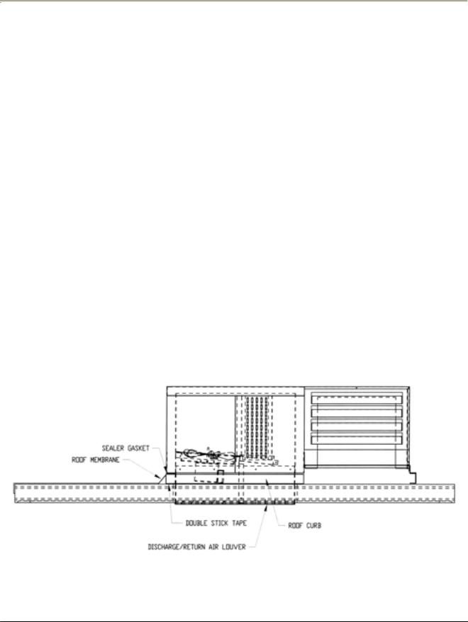
2.1 Installing the Roof Membrane and Curb – OUTDOOR UNITS ONLY
Top mount Polar-Pak units installed in outdoor applications must have a roof curb and membrane installed in order to ensure water-tightness. Refer to Figure 1 when following the instructions below.
•Remove roof curb from shipping skid and remove outer cover over double stick tape.
•Center curb over opening in ceiling panel
•With double-stick tape side down, press firmly in place.
•Place membrane roof material over the walk-in ceiling and cut an opening around perimeter of inside of roof curb.
•Following the directions in Section 2.2 below, lower the refrigeration system onto ceiling panel, making sure roof membrane material stays in place.
•Trim out roof curb around perimeter of walk-in.
Figure 1: Installation of the Roof Curb and Membrane for Outdoor Top Mount Polar-Pak Units
2
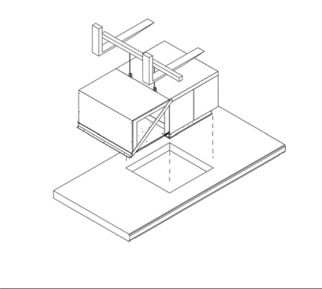
2.2Joining The Refrigeration Unit To The Ceiling Panel
•Place the ceiling panel to which the refrigeration system is to be connected on 12” high supports (Refer to Fig. 2). The space below the rectangular opening in the panel should be clear and free of obstructions.
NOTE: This assembly should take place as close as possible to the area where the walk-in is to be erected.
•Lift the refrigeration unit from its shipping crate and lower it into position. The refrigeration system may be lifted manually (CAUTION – refrigeration system is heavy – use reasonable care when handling) or with mechanical lifting equipment (Refer to Fig. 2).
•See note on page 5 concerning sealing evaporator box to ceiling panel.
Figure 2: Joining the Top-Mount Refrigeration System to the Ceiling Panel
3
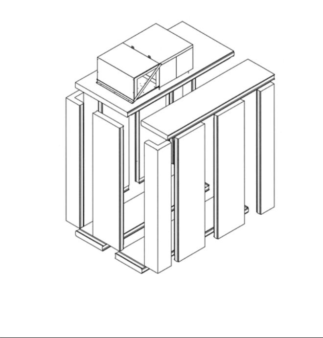
2.3 Walk-In Assembly
NOTE: Allow at least 18” of clearance around the refrigeration system when fully assembled. Failure to allow adequate clearance can result in poor system performance and premature compressor failure.
A separate installation instruction manual for the walk-in is included with the shipping crate. Please read it prior to installation. Figure 3 shows the spatial relationship of the parts:
Figure 3: Break-Away of Walk-in and Polar Pak Top-Mount Refrigeration System
4
The refrigeration assembly, consisting of the ceiling panel and the refrigeration unit, should be handled together.
 CAUTION: The refrigeration system is heavy, bulky, and has unequal weight distribution. When handling this equipment, please use reasonable care to prevent personal injury or damage to the equipment.
•Lay the floor panels and allow at least 18” of clearance around the refrigeration system when fully assembled.
•Stand up the back and the side panels ONLY and lock them together and to the floor panels.
•Moving from front to rear of walk-in, lift (manually or with lifting equipment) the refrigeration assembly over the side panels and lower it in place. Lock this panel to the back and side panels.
•Complete the assembly and installation of the walk-in per instructions provided with the walk-in.
•To insure there is no air infiltration into the walk-in, the gasket on the foamed evaporator box must seal all around the perimeter where it comes in contact with the ceiling panel. The condensing unit is attached to the evaporator box with screws in slotted holes. Loosen the screws, and push down on the evaporator to insure a tight seal, then tighten the screws.
3.0Power Hook-Up – Top Mount Models
 CAUTION: Power installation must be in full compliance with the National Electrical Code and all applicable local codes.
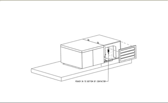
3.1Coolers
•Locate electrical box inside condensing unit compartment (Refer to Fig. 4):
Figure 4: Power Hook-Up for Polar Pak Top-Mount Coolers and Freezers
5

3.1Coolers (Cont’d)
•Connect one end of the power line to the bottom of the contactor provided in the electric box in the condensing unit compartment, and the other end to a properly sized electric outlet with an appropriate overcurrent protection device. Consult the unit name plate for power requirement.
•The cooler thermostat is preset to maintain walk-in temperature of 38 °F. Should any adjustment become necessary, please consult the section on thermostat operation.
•For information on defrost timer setting, please refer to Section 7.2 before replacing the end panel and turning on the power.
•Replace the end panel and turn on the power.
3.2Freezers
•Remove both louvered end panels by loosening and taking out mounting screws.
•Remove the top/side panel to expose the condensing unit. This is a one piece cover that fits over the condensing unit and ties to the base frame with screws at the top and on the bottom as shown in Figure 3.
•Connect one end of the power line to the bottom of the contactor provided in the electric box in the condensing unit compartment, and the other end to a properly sized electric outlet with an appropriate overcurrent protection device. Consult the unit name plate for power requirement.
•The defrost timer is programmed at the factory to initiate four defrosts daily at 4:00 AM, 10:00 AM, 4:00 PM, and 10:00 PM, respectively. The procedure for resetting the frequency and duration of the defrost cycle is presented in the section of the defrost timer operation and on the inside cover of the defrost timer box.
•Set the defrost timer clock by grasping the outer dial and rotating it in a CLOCKWISE direction. This will revolve the outer dial. Line up the correct time of day on the outer dial with the time pointer.
•The freezer thermostat is preset to maintain walk-in temperature of 0°F. Should any adjustment become necessary, please consult the section on thermostat operation.
•Replace the top/side panel and the end panel that covers the condenser coil.
•Turn power on and check. Reset the defrost timer clock if needed.
6

4.0Installation – Side Mount Models
4.1 Preparation for Installation
Normally the walk-in panels, refrigeration system, and installation instructions are shipped together. Transport the crate to the job site, uncrate, and remove the refrigeration system for installation.
 CAUTION: The side-mount Polar-Pak refrigeration systems are top heavy and the casters are designed for ease of installation ONLY. Transport the unit using a forklift or furniture dolly THROUGH THE BACK SIDE ONLY.
4.2 Walk-in Assembly
Set up the walk-in according to the installation instructions provided. Allow at least TWO FEET of clearance on the sides and back of the refrigeration system when fully assembled. Consult Fig. 5 for the correct spatial relationship of the parts.
NOTE: Failure to allow adequate clearance can result in poor system performance and premature compressor failure.
Figure 5: Break-away of Walk-in and Polar-Pak Side Mount Refrigeration System
7
 Loading...