

MAC Series
Operation Manual
Manitowoc Foodservice Walk-In Division
2915 Tennessee Avenue North
Parsons, TN 38363
Phone: 800-225-9916
www.manitowocfoodservice.com
www.manitowocfoodservice.com 800-225-9916 1
P/N 550003765 REV. 5
August, 2014
ECO KPR114586

www.manitowocfoodservice.com 800-225-9916 - 2 -

Table of Contents
Cool Start Guide ……………………………………………………………… 4 - 5
Safety Information ……………………………………………………………. 6
Condensing Unit Specifications …..………………………………….…….. 7
Evaporator Unit Specifications …………………………………………. ….. 8
Receiving Inspection ……………………………………………………. ….. 9
Locating and Mounting Condensing Units ………………………………… 9 – 10
Locating and Mounting Evaporator Coils …………………………………. 11
Condensing Unit and Evaporator Coil Wiring……………………………… 12
Piping …………………………………………………………………………. 12 - 14
Leak Test ……………………………………………………………………… 15
Evacuation ……………………………………………………………………. 16
Refrigerant Charging ………………………………………………………… 17
Compressor Mounts………………………………………………………….. 17
ArcticFox Interface Installation………………..…………………………….. 18 - 19
Operational Start-Up ….……………………………………………………… 20
Compressor Superheat ……………………………………………………… 21
Evaporator Superheat ………………………………………………………. 22
ArcticFox Features…………………………………………………………… 23
ArcticFox Wiring……………………………………………………………… 24
ArcticFox Initialization……………………………………………………….. 25
ArcticFox Button Functions…………………………………………………. 25
ArcticFox Programming……………………………………………………… 26 – 30
ArcticFox Alarm Codes………………………………………………………. 31
Sustaining Mode………………………………………………………………. 31
Data Logging…………………………………………………………………... 32
On Demand Defrost…………………………………………………………… 32
System Defaults………………………………………………………………. 32 – 36
Parts List………………………………………………………………………. 37 - 38
Maintenance ………………………………………………………………….. 39
Warranty Information ………………………………………………………… 40
System Start-Up Data Sheet ………………………………………………… 41
Appendices……. ……………………………………………………………… 42 – 51
A – Sensor Failure Codes……………………………………………. 42 – 43
B – Cooler or Freezer Set Up………………………………………… 44
C – Defrost Set Up…………………………………………………….. 45
D – Condensing Unit Wiring Diagram………………………………… 46 - 47
E – Air Defrost System Wiring Diagram…………………………….. 48
F – Electric Defrost System Wiring Diagram……………………….. 49
G – Standard Exterior Door Section Wiring…………………………. 50
H – Standard Partition Door Section Wiring ……………………….. 51
www.manitowocfoodservice.com 800-225-9916 - 3 -
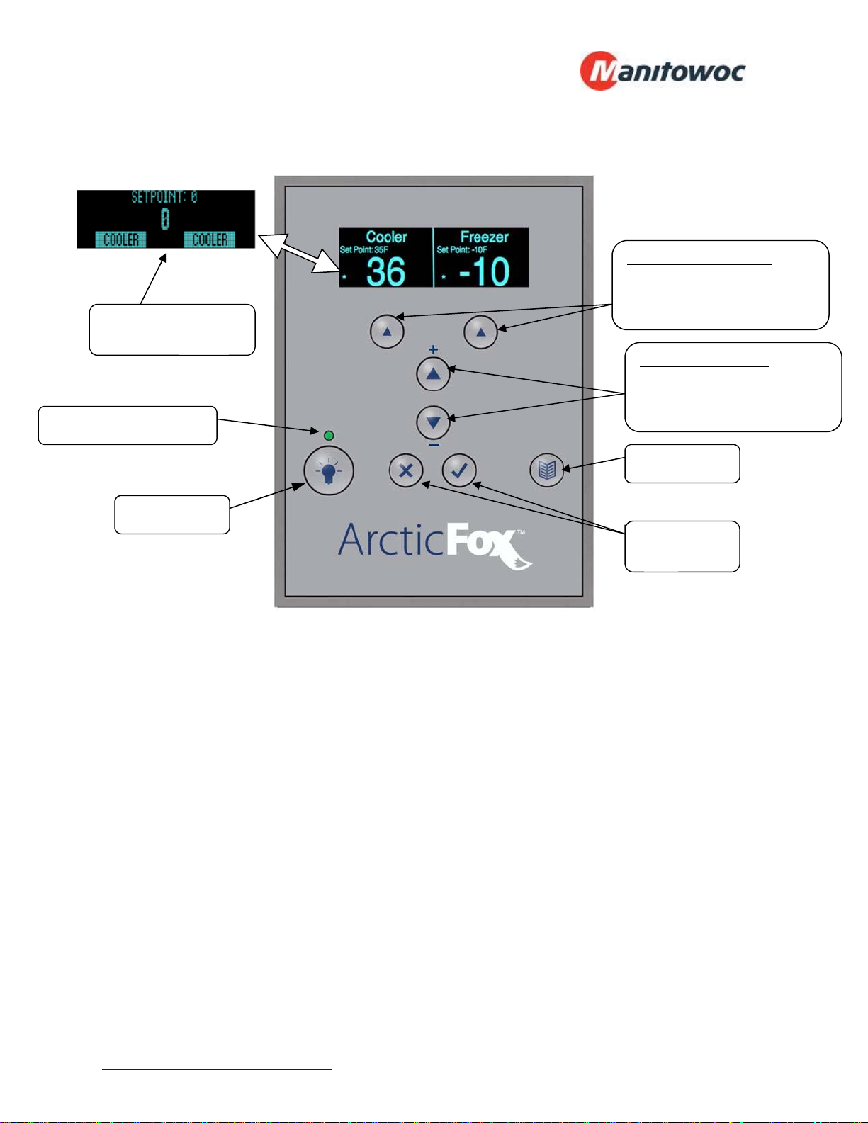
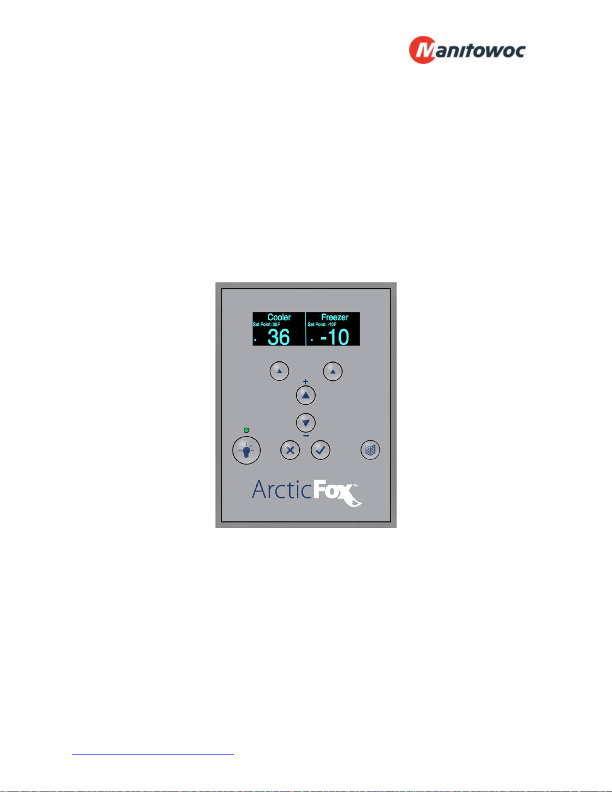
ArcticFox Cool Start Guide:
Alternative Display for
Single Unit
Manual Light Indicator
Soft Buttons (SB1, SB2)
Selects the item highlighted
on the display
Up and Down Arrows
Used to highlight items or
enter values
Menu Button
Light Button
Enter ()
Cancel (X)
Note: Dual control mode shown
General operation of the UI:
SB1 and SB2 perform or select the item that is highlighted above it. In the case
of the picture above pressing SB1 will activate the “Cooler” menu.
The Up and Down arrows are used to select items from a list or adjust the value
of a setting.
The <X> key has the following functionality:
o Cancels entry of current setting
o Silences the Alarm for 5 minutes
o Stops the status scrolling on the top of the display (The enter key also
stops the scrolling). Pressing either the <X> or the <> key will resume
scrolling (there may be a 1-2 second delay for the scrolling to start again.
With the scrolling stopped the Up or Down arrows change the parameter shown.
The light key turns on both the Cooler and Freezer’s lights (if walk-in is so
equipped).
The <Menu> key allows access (with password) to the system parameters and
other service features.
The <> key “enters” or “accepts” a choice while changing settings.
www.manitowocfoodservice.com 800-225-9916 - 4 -
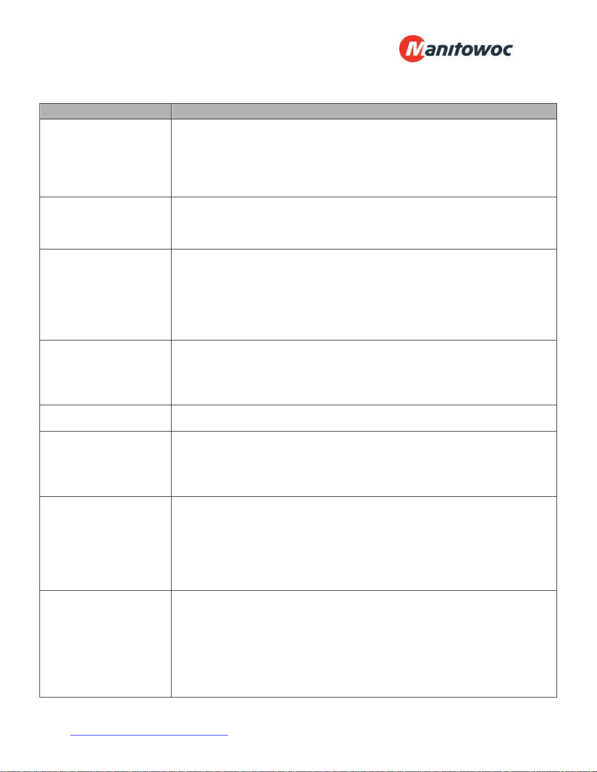
Function Steps
Set Time and Date
Set Temperatures
Set Temperature Alarms
Set Door Alarm Time
Silence Alarms
Clearing Alarms
Set User Password
Set Service Password
1. Press the <Menu> button and enter password (AAAA is default)
2. Enter password, then press <>
3. Press <Down> to scroll to "Set Date & Time", then press <>
4. Press <Up> or <Down> to select the hour, then press <>
5. Press SB2 (under NEXT) to move on to the minute screen.
6. Follow steps until time & date are set, then press < X > to return to main display
1. Press <SB1> or <SB2> and enter password (AAAA is default)
2. Press <Up> or <Down> to change the desired temperature
3. Press <> to enter selection
4. Press <X> to return to main display
1. Press <SB1> or <SB2> and enter password (AAAA is default)
2. Press <SB2> to navigate to "SET COOLER HIGH ALARM"
3. Press <Up> or <Down> to obtain the desired setting
4. Press <SB2> to navigate to "SET COOLER LOW ALARM"
5. Press <Up> or <Down> to obtain the desired setting
6. Press <> to enter selection
7. Press <X> to return to main display
1. Press <SB1> or <SB2> and enter password (AAAA is default)
2. Press <SB2> to navigate to "SET COOLER DOOR ALARM TIME"
3. Press <Up> or <Down> to obtain the desired setting
4. Press <> to enter selection
5. Press <X> to return to main display
Pressing <X> will silence the alarm for 5 minutes
Pressing <X> and <> simultaneously for 3 seconds will permanently silence alarm
1. Press <SB1> or <SB2> and enter password (AAAA is default)
2. Press <SB1> to navigate to "CLEAR COOLER ALARMS"
3. Press <Up> or <Down> to obtain the desired setting
4. Press <> to enter selection
5. Press <X> to return to main display
1. Press the <Menu> button
2. Enter password, then press <>
3. Press <Down> to scroll to "Set User Password", then press <>
4. Enter old password (default is AAAA) and press <>
5. Enter new password and press <>
6. Re-enter new password to confirm and press <>
7. Press <x> twice to return to main display.
1. Press the <Menu> button
2. Enter password, then press <>
3. Press <Down> to scroll to "Service Menu", then press <>
4. Press <Down> to scroll to "Set Service Password", then press <>
5. Enter old password (default is ZZZZ) and press <>
6. Enter new password and press <>
7. Re-enter new password to confirm and press <>
8. Press <x> three times to return to main display.
www.manitowocfoodservice.com 800-225-9916 - 5 -
Note: If the walk-in is a freezer, substitute freezer in place of cooler nomenclature.
General Safety Information:
Read this manual carefully before beginning the installation and operation of the
refrigeration system. Special attention is required to all sections identified with the
following warning and caution notices:
WARNING
Text in a Warning box alerts you to a potential personal injury situation. Read each
Warning statement before proceeding and work carefully.
CAUTION
Text in a Caution box alerts you to a situation in which you could damage the
refrigeration system. Read each Caution statement before proceeding and work
carefully.
Disregarding these special notices may result in personal injury and/or damage to the
refrigeration system.
Safety Notices:
Installation and maintenance/servicing are to be performed only by trained and
qualified personnel familiar with commercial refrigeration systems.
Ensure that all field wiring conforms to the equipment requirements and all
applicable local and national codes.
Disconnect all power sources before installing the controller wiring.
Disconnect all power sources before servicing the refrigeration equipment.
Sheet metal and coil surfaces have sharp edges. Use appropriate protective
gloves to prevent injury.
Use appropriate eye protection during installation and servicing.
www.manitowocfoodservice.com 800-225-9916 - 6 -
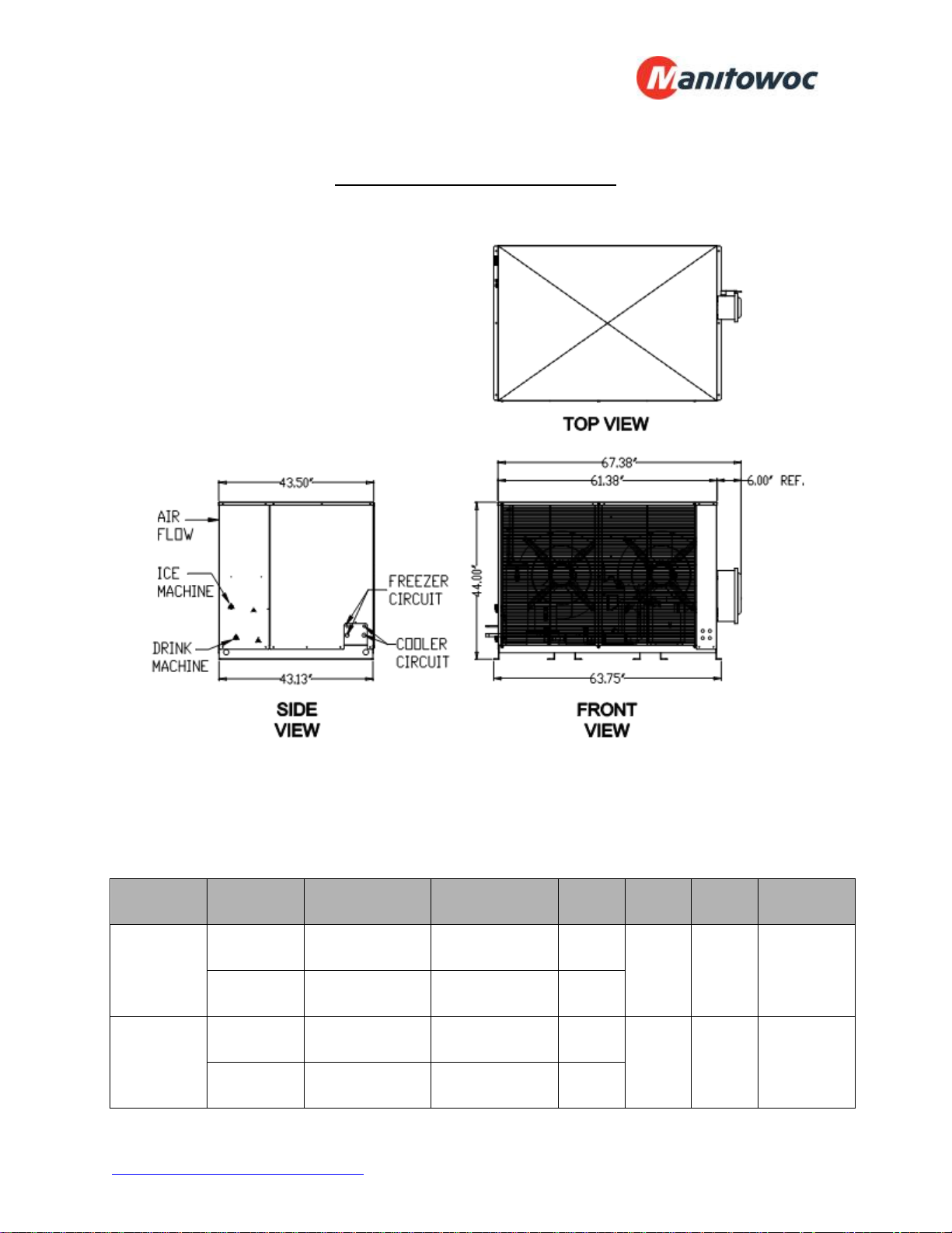
Condensing Unit Specifications
Model Location Compressor Voltage HP MCA MOP
FREEZER ZF13K4E-TF5 208-230/3/60 4.5
MAC 7
COOLER CF04K6E-TF5 208-230/3/60 1.5
FREEZER ZF15K4E-TF5 208-230/3/60 5.5
MAC 8
COOLER CF04K6E-TF5 208-230/3/60 1.5
31.3 40 660 lbs
38.8 50 660 lbs
Approx.
Weight
MCA – Minimum Circuit Ampacity.
MOP – Maximum Overcurrent Protection.
www.manitowocfoodservice.com 800-225-9916 - 7 -
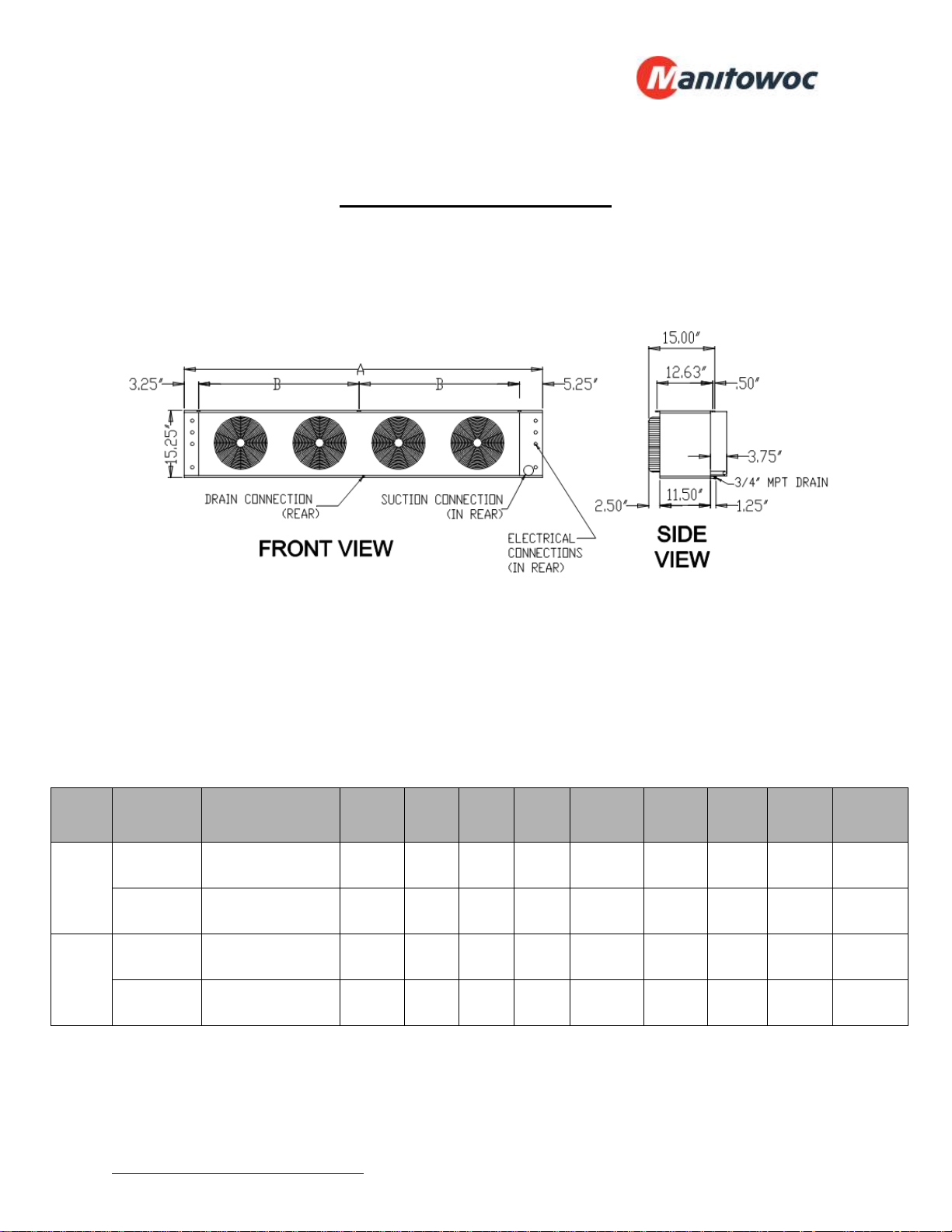
Evaporator Unit Specifications
No.
of
Fans
A B
Suction
OD
Liquid
OD
Motor
Amps
Heater
Amps
Model Location
FREEZER EL36-140-2MAC 14,000 3 63.50 55.00 7/8" 3/8" 1.35 13.00 115 lbs
MAC
7
COOLER AM28-134-2MAC 13,400 2 45.50 37.00 7/8" 3/8" 0.90 n/a 77 lbs
FREEZER EL46-185-2MAC 18,500 4 81.50 36.50 1-1/8" 3/8" 1.80 13.00 155 lbs
MAC
8
COOLER AM28-134-2MAC 13,400 2 45.50 37.00 7/8" 3/8" 0.90 n/a 77 lbs
Evaporator
Model
BTUH
Approx.
Weight
www.manitowocfoodservice.com 800-225-9916 - 8 -
Receiving Inspection
Check the shipment carefully and compare to the bill of lading. Account for all items
listed and inspect each container for damage. Carefully inspect for any concealed
damage. Report any shortages or damages to the carrier, note on the bill of lading, and
file a freight claim.
Damaged material cannot be returned to the manufacturer without prior approval. A
Return Material Authorization (RMA) must be obtained. Contact a sales representative
at 800-826-7036.
Locating and Mounting Condensing Unit
General Guidelines:
Check the selected installation location to ensure that racks, braces, flooring,
foundations, etc. are adequate to support the condensing unit weight.
The installation location is clean, dry, and level.
Locate away from corrosive and noise sensitive atmospheres.
Use the condensing unit skid and base when moving the unit. Do not remove
unit from skid until the unit is moved to the mounting location.
Mount the condensing unit base to pads or structural rails using properly sized
bolts through the unit base.
WARNING
Do not lift the condensing unit by the refrigerant tubing or components. These features
will not support the condensing unit weight. Injury and unit damage may occur!
CAUTION
Do not leave the condensing unit mounted to the wooden skid. This prevents all of the
unit supports from contacting the mounting surface. Excessive vibration and premature
equipment failure can occur.
www.manitowocfoodservice.com 800-225-9916 - 9 -
Clearance Requirements:
Locate where there is a sufficient and unrestricted supply of clean ambient air.
Locate where there is adequate space for the removal of the heated discharged
air from the condensing unit area.
Do not position multiple units so that discharge air from one unit is blowing into
the condenser inlet air of the other unit.
All sides of the unit should be positioned a minimum distance equal to the total
width of the condensing unit away from any other unit, wall, or obstruction.
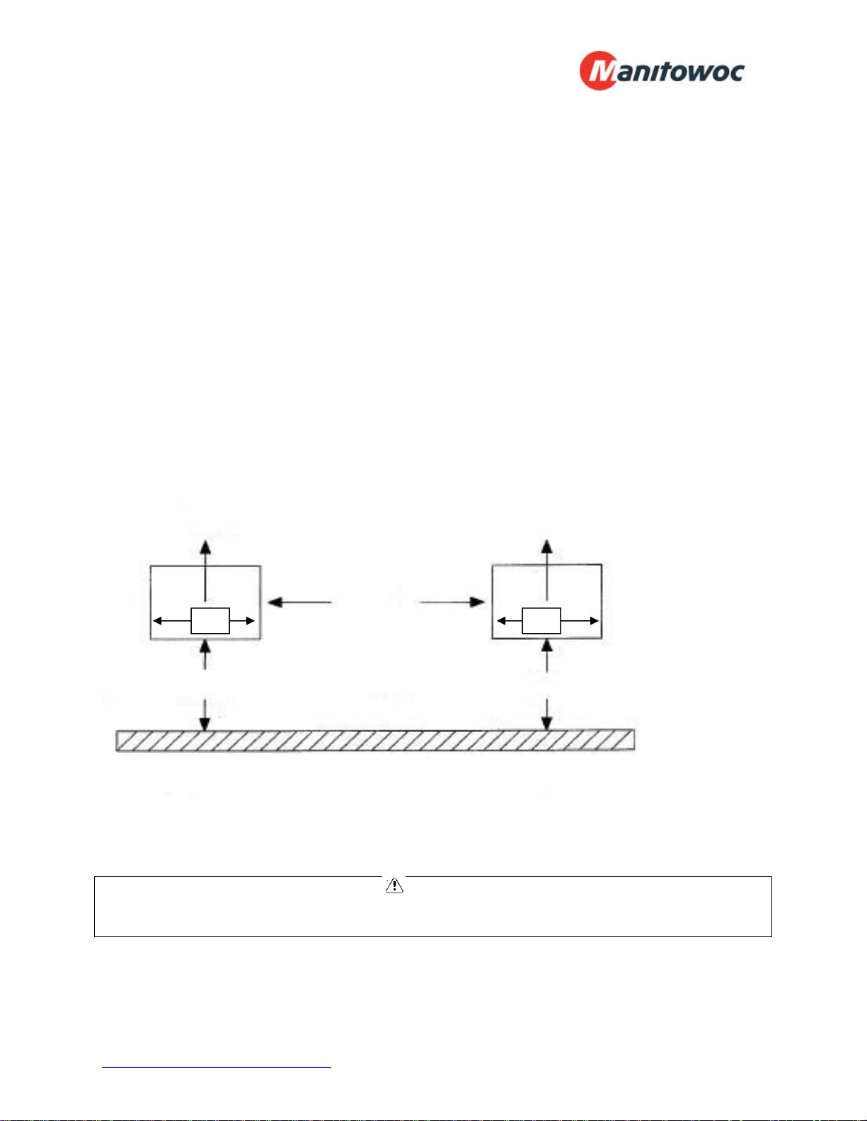
Example of Multiple Units with Horizontal Airflow
AIR
FLOW
AIR
FLOW
MINIMUM
DISTANCE
24”
INTAKE AIR
MINIMUM DISTANCE 24”
(VIEWED FROM ABOVE)
24”
BUILDING WALL
24”
INTAKE AIR
MINIMUM DISTANCE 24”
CAUTION
Failure to observe clearance and air flow requirements will result in poor system
performance and premature equipment failure!
www.manitowocfoodservice.com 800-225-9916 - 10 -
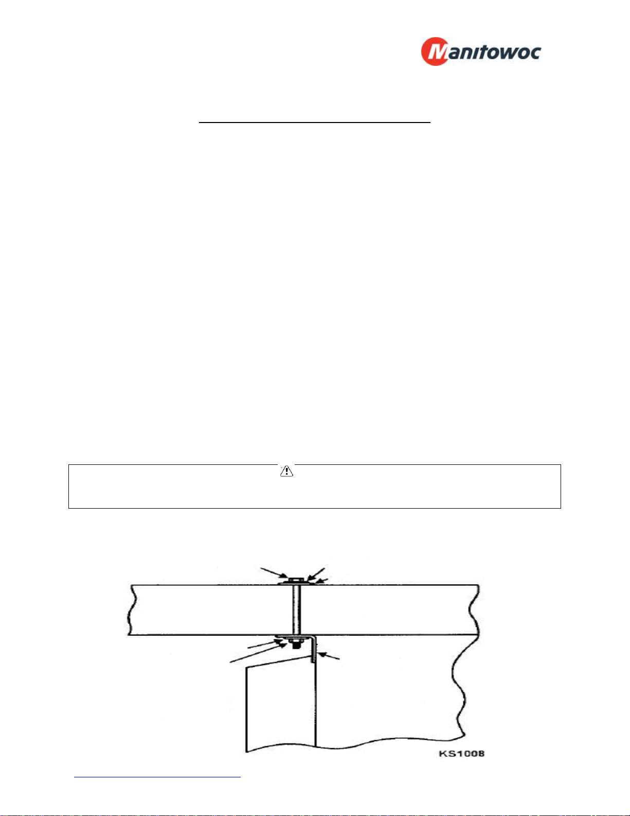
Locating and Mounting Evaporator Coil
General Guidelines:
Do not place the evaporator above or close to door openings. This will help
prevent potential icing problems.
Allow a minimum clearance equal to or greater than the coil height on all sides of
the coil for proper air flow and service access. This does not apply to fan side.
Use the evaporator coil for a template to locate and drill the mounting holes (1/2”
diameter).
Place a 1” and a 1-5/8” washer on each nylon bolt and insert through the drilled
mounting holes.
Lift the evaporator coil until the nylon bolts extend through the mounting
brackets.
Install washers and secure with nuts. Tighten until the coil is firm against the
ceiling. The evaporator coil must be level.
Additional information is available in the installation manual supplied with the
evaporator.
CAUTION
Failure to observe clearance and air flow requirements will result in poor system
performance and premature equipment failure!
Evaporator Coil Mounting Diagram
Nylon Bolt 1” O.D. washer
1-5/8” O.D. washer
1” O.D. washer
Nut
Note: Fasteners are
supplied in the
mounting kit.
Evaporator
Mounting
Bracket
www.manitowocfoodservice.com 800-225-9916 - 11 -
Wiring
All electrical connections and routing must comply with local and national codes. Do not
modify the factory installed wiring without written factory approval. The field wiring must
enter through the knockouts provided. Refer to the nameplate on the condensing or
evaporator coil to determine the proper electrical power supply. Wire type should be of
copper conductor only and properly sized to handle the electrical load. The unit and coil
must be properly grounded. Condensing unit wiring diagrams are attached inside the
electrical box cover. Evaporator coil wiring diagrams are located inside the evaporator
end panel. Copies of the wiring diagrams are also available in the back of this manual.
WARNING
All wiring must comply with local and national codes. Wiring must be performed only by
a refrigeration technician or certified electrician. Failure to follow these guidelines may
result in injury!
CAUTION
Check all wiring connections, including factory terminals, before operation. Connections
can become loose during shipment and installation.
Piping
General Requirements:
All refrigeration piping and components are to be installed in accordance with applicable
local and national codes and in conformance with industry refrigeration guidelines to
ensure proper operation of the refrigeration system. Only refrigeration grade copper
tubing should be used. Long radius elbows should be used. Short radius elbows have
points of excessive stress concentration and are subject to breaking at these points, do
www.manitowocfoodservice.com 800-225-9916 - 12 -
not use short radius elbows. Suction lines must be insulated with a minimum 1” thick
armaflex to reduce heat pick-up.
Cleanliness:
Condensing units and evaporator coils are cleaned and dehydrated at the factory. The
condensing unit must remain closed and pressurized until the piping is complete and
final connections are ready to be made.
CAUTION
The maximum air exposure for dehydrated condensing units is 15 minutes. Systems
exposed longer than 15 minutes must have the compressor oil and drier filter replaced.
Leaving a system exposed to the atmosphere for more than 15 minutes can result in
premature system failure.
Note: PC model condensing units are supplied with a refrigerant charge. PR model
condensing units are supplied with a dry holding charge.
Do not remove system tubing covers until work is ready to be performed. Ensure that
all refrigeration tubing is clean and dry prior to installation. Use only tubing cutters when
trimming tubing to the proper length. Do not use saws to cut tubing.
CAUTION
The use of saws to cut tubing can contaminate the system with copper chips causing
premature system failure.
Brazing joints require a dry inert gas, typically nitrogen, be passed through the lines at a
low pressure to prevent scaling and oxidation. Use only silver solder brazing alloys.
Minimize the amount of flux to prevent internal contamination. Flux only the male
portion of the joint. Thoroughly clean fluxed joints after brazing.
CAUTION
Dry inert gas must be passed through the system while brazing to prevent scaling and
oxidation. Scaling and oxides can clog refrigeration components resulting in system
failure.
Pipe Supports:
All tubing should be supported in a least two locations (near the end of each tubing run).
Long runs will require additional support. As a guide, support 3/8” to 7/8” pipe every five
feet, 1-1/8” to 1-3/8” every seven feet, and 1-5/8” to 2-1/8” every ten feet. Do not leave
a corner unsupported when changing directions. Place supports within 2 feet of each
direction change. Piping that is attached to a vibrating object (such as a compressor or
www.manitowocfoodservice.com 800-225-9916 - 13 -
compressor base) must be supported in a manner that will not restrict the movement of
the vibrating object. Rigid mounting will fatigue the tubing causing refrigerant leaks.
Oil Traps:
To ensure proper oil return to the compressor, a P-type oil trap should be installed at
the base of each suction riser of four feet or more. The suction trap must be the same
size as the suction line. Additional traps are necessary for long vertical risers. Add a
trap for each length of pipe (approximately 20 feet) to insure proper oil return. Suction
lines must slope ¼” per 10 feet toward the compressor. Install a suction line trap at the
evaporator outlet if the suction line rises to a point higher than the connection on the
evaporator.
CAUTION
Failure to properly install oil traps can prevent sufficient oil return to the compressor
resulting in premature compressor failure.
Drain Lines:
Evaporator coil drain lines should be pitched a minimum of ½” per foot to allow proper
drainage and exit the walk-in as quickly as possible. Insulate and seal the drain line
where it passes through the wall. Copper drain line is required. If the refrigerated
space is 33°F or lower, drain line insulation and heat tape are required. Drain lines
must be insulated with minimum ½” thick armaflex. The drain line heat tape must be
wrapped around the copper drain line. Do not locate bends, elbows, or drain traps
within the refrigerated space. Do not reduce the drain line size. Locate a drain line Ptrap outside of the refrigerated space. Any traps exposed to low ambient temperatures
should be wrapped with a drain line heater (provide 20 watts of heat per foot of drain
line at 0°F, 30 watts per foot at -20°F.
www.manitowocfoodservice.com 800-225-9916 - 14 -
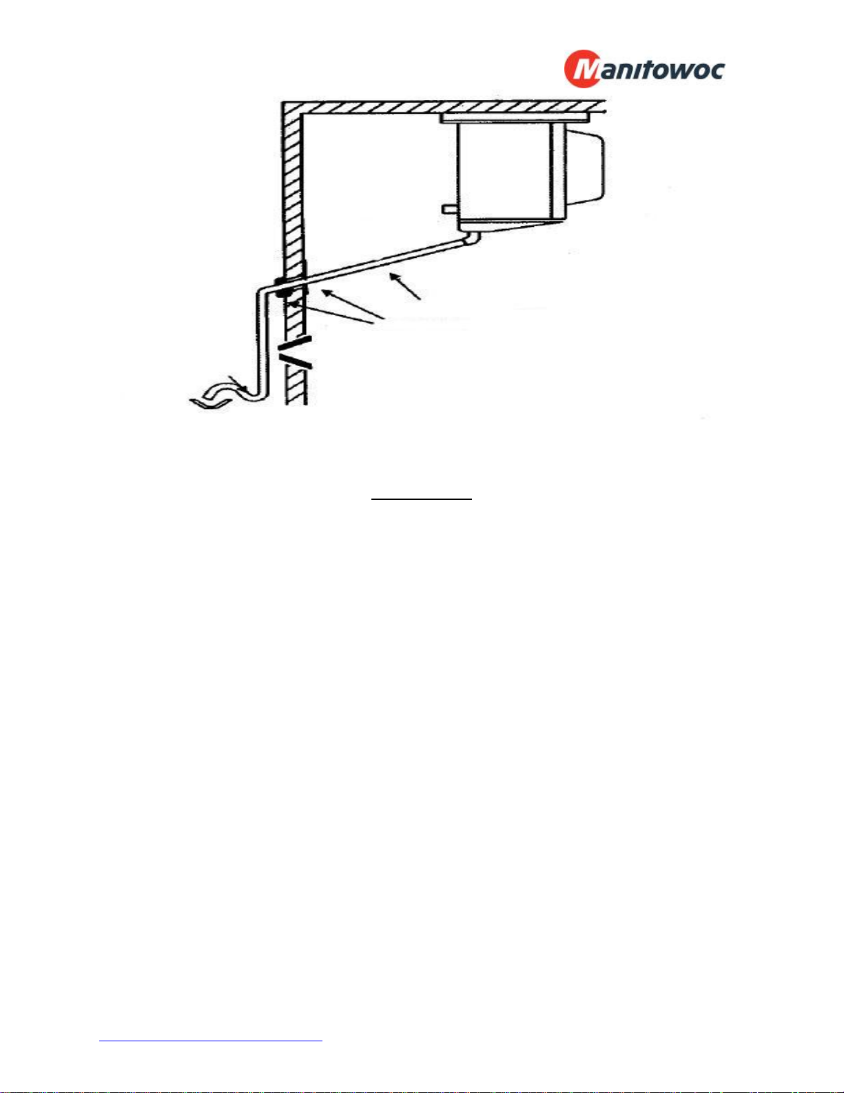
Pitch drain line
½” per foot
Seal and
Insulate
Typical Drain Installation
P-Trap
Leak Testing
After all connections are complete the refrigeration system must be tested for leaks.
Failure to perform a leak test can result in unsatisfactory system performance,
additional servicing and service costs, and possible system failure. Leak test should be
performed using an electronic leak detector. All joints and components, both factory
and field installed, should be thoroughly inspected for leaks. The system installation
must be leak free!
Leak Testing “PR” model systems:
Open both the liquid and suction service valves.
Ensure the solenoid valve is energized and open.
Add 50 psi refrigerant, then pressurize with dry nitrogen to the low side test
pressure identified on the unit rating label.
Allow thirty minutes for refrigerant to reach all parts of the system.
Check all joints and components with an electronic leak detector.
Leak Testing “PC” model systems:
Leave the service valves closed, the condensing unit is charged with refrigerant.
Ensure the solenoid valve is energized and open.
www.manitowocfoodservice.com 800-225-9916 - 15 -
Add 50 psi refrigerant, then pressurize with dry nitrogen to the low side test
pressure identified on the unit rating label.
Allow thirty minutes for refrigerant to reach all parts of the system.
Check all joints and components with an electronic leak detector.
If a leak is detected, relieve the pressure and/or reclaim the refrigerant and repair the
leak. If additional brazing is required, pass a dry inert gas (nitrogen) through the system
to prevent contamination. Retest the system as outlined above until no leaks are
detected.
CAUTION
If a braze joint is detected leaking, dry inert gas must be passed through the system
while repairing the joint to prevent scaling and oxidation. Scaling and oxides can clog
refrigeration components resulting in system failure.
CAUTION
Always use the system specified refrigerant when pressuring to perform a leak test.
System Evacuation
Evacuation of the refrigeration system is necessary to remove all air and moisture from
the system. A reliable rotary vacuum pump with an accurate deep vacuum gauge is
recommended. Do not use the system compressor as a vacuum pump and do not
operate the compressor while the system is under vacuum.
Evacuation of “PR” model systems:
Open both the liquid and suction service valves.
Ensure the solenoid valve is energized and open.
Connect vacuum pump to the liquid and suction service valves.
Evacuate the system to 250 microns and maintain for a minimum of 4 hours.
Perform a vacuum decay test for a minimum of ten minutes to ensure the system
is leak free and dry.
Evacuation of “PC” model systems:
Leave the service valves closed, the condensing unit has been evacuated and is
charged with refrigerant.
Ensure the solenoid valve is energized and open.
www.manitowocfoodservice.com 800-225-9916 - 16 -

Connect vacuum pump to the liquid and suction service valves.
Evacuate the system to 250 microns and maintain for a minimum of 4 hours.
Perform a vacuum decay test for a minimum of ten minutes to ensure the system
is leak free and dry.
CAUTION
Do not use the system compressor to evacuate the system. Do not start the
compressor while the system is under vacuum. This may damage the compressor and
cause premature system failure.
Refrigerant Charging
The refrigerant charge should be added to the system through the liquid line service
valve. Do not charge liquid refrigerant into the suction service valve! The initial charge
should be determined by weight and sight glass indication. Start the system. If the
condensing temperature is 105° F or greater, charge the system until the sight glass
clears. If the condensing unit temperature is below 105° F, reduce the condenser face
surface area to raise the discharge pressures above 105° F and proceed to charge to a
clear sight glass. Return to a full condenser face area when charging is complete.
CAUTION
Do not charge liquid refrigerant into the suction service valve. Do not overcharge the
system. These conditions can permit liquid refrigerant to enter the compressor and
cause damage to internal components resulting in premature system failure.
Note: PC model condensers are charged at the factory with 17 lbs. (freezer) and 8-1/2
lbs (cooler) of R404A refrigerant. Due to site variances, an additional charge may be
required.
Operational Start-Up
The first 2 – 4 hours of operation after initial start-up is a critical time. Do not just start
the system and leave. Pressure values, compressor and evaporator superheat, and
inspecting for excessive vibrations and loose connections are some of checks that must
be performed prior to leaving the system.
Pre-Start Checks:
Verify that all service valves are fully open.
Ensure that all refrigerant and electrical connections are tight.
www.manitowocfoodservice.com 800-225-9916 - 17 -

Verify that the wiring and piping is properly routed and secured.
The compressor mounting bolts are properly adjusted.
All fan motors and mounting brackets are tight.
The condensing unit base and evaporator coil are properly secured.
ArcticFox User Interface is properly installed and mounted.
Compressor Mounts:
Check the compressor mounting bolts to ensure the nuts have not become loose during
shipment.
CAUTION
Failure to ensure the compressor mounts are properly tightened can result in fatigue to
the system piping causing leaks and poor system performance.
ArcticFox User Interface Installation and Initialization:
The user interface is designed to sit on the manager’s desk, but can be field modified to
mount directly to the walk-in or wall. The User Interface has a port on top for a CAT5e
cable.
To mount the user interface to a vertical surface using the UI Wall Mounting Assembly:
Select mounting location (allow 12” min. clearance for UI away from high traffic
areas and protected from direct contact with liquids).
Remove the backing from the (2) 2-1/2” long lengths of double sided tape located
on the back of the assembly.
Press the assembly onto the pre-selected mounting location surface ensuring the
assembly is level and plumb.
Secure the assembly to the vertical surface using (4) 10-16 x ½” self tapping
screws.
Once the user interface is secured in its stationary location, connect the CAT5e cable
from VFD-UI indicated on the evaporator coil to the UI ensuring the CAT5e cable is
securely fastened to adjacent surfaces.
Once unit is powered up, the UI will begin the initialization process.
At initialization the Start-up screen is shown, followed by an Initialization screen,
followed by the Main screen. The Start-up screen will flow directly into the main screen
without user interaction.
www.manitowocfoodservice.com 800-225-9916 - 18 -

The status bar is located at the top of the display and will continuously alternate through
the status of the key parts of the system. These include:
Unit State – (Idle, Idle-W, Cooling, Defrost)
Door Status – (Open, Closed). Unit will read ‘closed’ if the door functionality is
not utilized.
Light Status – (On, Off). Unit will read ‘off’ if the light functionality is not utilized.
Temperature set point – (35° F for coolers, -10° F for freezers).
Alarms – Any alarm condition results in an audible alarm and visual alarm.
CAUTION
If a cooler/freezer combo is operating from a single UI, connect additional factory
supplied CAT5e cable from Optional Modules at the freezer evaporator to the Optional
Modules at the cooler evaportor.
Set the time and date:
Press the <Menu> button and enter password (default is AAAA)
Enter password, then press <√>.
Press <Down> to scroll to “Set Date & Time”, then press <√>.
Press<Up> or <Down> to select the hour, then press <√>
Press SB2 (under next) to move on to the minute screen.
Follow the steps above until the time and date are set, then press <√> to return
to the Menu screen.
Press <X> twice to return to main display.
Set the Manager Password:
Press the <Menu> button
Enter password, then press <√>.
Press <Down> to scroll to “Set User Password”, then press <√>.
Enter old password (default is AAAA) and press <√>
Enter new password and press <√>
Re-enter new password and press <√>
www.manitowocfoodservice.com 800-225-9916 - 19 -

Press <X> twice to return to main display
Set the Service Password:
Press the <Menu> button
Enter password, then press <√>.
Press <Down> to scroll to “Service Menu”, then press <√>.
Press <Down> to scroll to “Set Service Password”, then press <√>.
Enter old password (default is ZZZZ) and press <√>
Enter new password and press <√>
Re-enter new password and press <√>
Press <X> three times to return to main display
Start-Up Procedure:
CAUTION
Do not start the system while in a vacuum. Do not leave the system unattended until
normal operating conditions are achieved.
Operate the system for a minimum of two hours and perform checks of the following:
Check the compressor discharge and suction pressures to ensure they are in the
normal operating range.
Check the liquid line sight glass for proper refrigerant charge.
Check the voltage and amperage at the compressor terminals. Voltage must be
within +10% or -5% of the rating indicted on the condensing unit name plate. On
three phase compressors, verify there is a balanced load.
Check all fans on the evaporator coil and condensing unit to be sure they are
operational and turning in the correct direction.
Check the piping and electrical connections for vibration. Add supports and
strapping if needed.
Check the crankcase heater operation (if equipped).
The defrost times and settings are pre-set and controlled by ArcticFox.
Set temperature is pre-set and controlled by ArcticFox.
www.manitowocfoodservice.com 800-225-9916 - 20 -

Check the compressor and evaporator superheat (pages 21-22). Superheat is
pre-set and controlled by ArcticFox.
After all system checks have been checked, properly adjusted, and verified, replace all
Schrader caps, service valve caps, electrical box covers, housings, etc. File a copy of
this manual for future reference.
Compressor Superheat:
CAUTION
Failure to check and properly adjust compressor superheat can result in premature
system failure.
Compressor superheat is a critical value that must be checked. Check the compressor
superheat as follows:
Determine the suction pressure at the suction service valve of the compressor.
Determine the saturation temperature at the observed suction pressure using
refrigeration pressure temperature tables.
Measure the suction line temperature 6 -10 inches away from the compressor.
Subtract the saturation temperature (step 2) from the measured temperature
(step 3). The difference is the superheat of suction gas.
A low suction superheat can cause liquid to return to the compressor. This will cause
dilution of the oil and eventual failure of the bearings, rings and valves. A high suction
superheat will cause excessive discharge temperatures, which cause a breakdown of
the oil. This causes piston ring wear, and piston and cylinder wall damage. System
capacity decreases as the suction superheat increases. For maximum system capacity,
keep the suction superheat as low as practical. Copeland requires a minimum
compressor superheat of 20°F; however, to improve compressor life, 25°F to 40°F is
www.manitowocfoodservice.com 800-225-9916 - 21 -

preferred. Adjust the superheat using the ArcticFox controller. Refer to “Evaporator
Superheat” on the next page for more information.
Evaporator Superheat:
Check the evaporator superheat once the walk-in has reached the desired temperature.
Generally, systems with a design temperature drop of 10°F should have an evaporator
superheat value of 6° - 10°F on freezers and 8° - 12°F on coolers for maximum
efficiency. The evaporator superheat is pre-set for 8°F at the factory.
To determine the evaporator superheat:
1. Measure the suction pressure at the evaporator outlet.
2. Convert the pressure to saturation temperature referencing a temperature-pressure
chart.
3. Measure the temperature of the suction line near the EEV sensor. Do not remove
the insulation from around the sensor.
4. Subtract the saturation temperature reading (step 2) from the measured temperature
(step 3). The difference is the evaporator superheat.
www.manitowocfoodservice.com 800-225-9916 - 22 -

Temperature minus
pressure converted
to temperature
equals superheat
Pressure
Temperature
Determining Evaporator Superheat
CAUTION
Minimum compressor superheat of 20°F may override these recommendations on
systems with short line runs.
CAUTION
The condensing unit must have the discharge pressure above the equivalent 105°F
condensing pressure (reference refrigerant charging on page 17).
CAUTION
Correct location and full contact of the EEV sensor is extremely important for proper
system performance. EEV sensor is premounted and insulated before shipment.
www.manitowocfoodservice.com 800-225-9916 - 23 -

ArcticFoxFeatures
Alternative Display for
Single Unit
Manual Light Indicator
Light Button
Soft Buttons (SB1, SB2)
Selects the item highlighted
on the display
Up and Down Arrows
Used to highlight items or
enter values
Menu Button
Enter ()
Cancel (X)
Note: Dual control mode shown
The ArcticFox Control System consists of a User Interface Control (Desk or wall
mounted) and one or two evaporator coil assemblies with a factory mounted Smart
Relay Board in each coil. The Smart Relay Board is factory configured to match the coil
application (cooler or freezer). The User Interface Control is also referred to as the UI.
The standard features are shown below:
Monitoring of the complete refrigeration system
Programmable Operating Parameters
Vacuum Fluorescence Display which shows:
o Box temperature(s)
o Set Point(s)
o Alarm Conditions
Data Logging (Flash Drive)
Demand Defrost
Audible Alarm
Password Protection
www.manitowocfoodservice.com 800-225-9916 - 24 -

Wiring:
All low voltage wiring must be run separate from line voltage:
User Interface Wiring
The ArcticFox User Interface does not require an external power source. The only
connection to it is a CAT-5e cable that originates at the Evaporator Coil Assembly.
Evaporator Coil Wiring
The ArcticFox Smart Relay Board is mounted in each Evaporator Coil Assembly and
controls:
Refrigeration System
Electric Expansion Valve
Walk-In Cooler/Freezer Interior Light(s) - optional
Walk-In Cooler/Freezer Door Heater(s) - optional
Walk-In Cooler/Freezer Alarms
There are three terminal boards located in the Evaporator Coil Assembly used for field
wiring:
Power Supply Terminal Block
The Power Supply Terminal Block must be supplied with 208-230/60/1 field connected
power with ground. (See wiring diagram, Appendix E/F)
Terminal Block TB3, Low Voltage Wiring
Low voltage wiring is brought to terminal Block TB3 when optional Door Sensor
Switches are used. It is recommended that 18 gauge wire be used. (See wiring
diagram, Appendix E/F)
Terminal Block TB4 Wiring
When Door Heaters and/or Lights are to be controlled by ArcticFox, they must be wired
to Terminal Block 4. (See wiring diagram, Appendix E/F)
www.manitowocfoodservice.com 800-225-9916 - 25 -

Initialization of ArcticFox Control System:
When power is first applied to the ArcticFox User Interface, it checks the configuration
of the system to which it is connected. If a Cooler/Freezer combo box is wired to it, the
controller automatically connects. If the configuration is not a Cooler/Freezer combo
box, refer to “set up” section for instructions to manually configure controller. This
configuration can consist of the following options:
One “Cooler” evaporator
One “Freezer” evaporator
One “Cooler/Freezer” combo, separate compartments
It is recommended (but not required) that the refrigeration system be operational before
attaching the ArcticFox User Interface.
Button Functions:
Light (☼) – This is used to turn on all of the lights that are wired into the Smart
Relay Board(s). The Led indicator light reflects the status of the light button – not
necessarily the actual light condition. Pushing the light button while the lights are
on will shut them off (after the time delay expires). This does not apply when the
lights are not controlled by the ArcticFox controller.
System Selection Arrow (▲) – This is used to select the system to be
programmed.
Up, Down Arrows (▲, ▼) – These buttons are used to scroll through menus,
parameters and settings.
Cancel (X) – Depressing this button cancels the immediately preceding input.
Enter (√) – Depressing this button “accepts” the immediately preceding input.
Menu ( ) – Depressing this button brings up the main menu after the user
enters and accepts the password.
www.manitowocfoodservice.com 800-225-9916 - 26 -

Programming ArcticFox Control System:
Initial Set-Up:
The Smart Relay Board located in the Evaporator Coil Assembly is factory configured
to match the Evaporator application (Cooler or Freezer). The UI is factory configured
for a Cooler/Freezer combo box so no changes are required for this application.
To make a program change:
Select the appropriate application (Cooler or Freezer) by pressing the (▲) button below it.
Enter password by scrolling (▲,▼arrows), selecting (▲), then entering (√)
Set box temperature
Set high temp alarm
Set low temp alarm
Set door alarm time (1 minute to 60 minutes)
Clear alarms
Additional Program Changes:
To make additional changes or to view current settings available through different
menus, press the menu button. Multiple pushes allow scrolling through the menu
layers.
www.manitowocfoodservice.com 800-225-9916 - 27 -

Program Changes:
Main Menu (Manager’s Menu)
Information Menu
UI (VFD) Info
o BT (Boot Table)
o SW (Software Version)
o BLD (Build Date)
o VFD (Temperature)
o DT (Current Date)
o TM (Current Time)
Cooler Evaporator Info
o BT (Boot Table)
o SW (Software Version)
o HW (Hardware Version)
o MB (Modbus Version)
Freezer Evaporator Info (If Installed)
Set Date and Time
Set User Password
Service Menu
Cooler Service Menu
o Cooler Setup
Set Cooler Superheat – 4F to 20F
Set Cooler Hysterisis – 1F to 5F
Set Cooler Off Hysterisis – 1F to 5F
Cooler Door Sensor Enabled
- None
- Doors 1 or 2
- Doors 1 and 2
- Cooler Door Heater On Time – 0hr to 23hr 45 min.
- Cooler Door Heater Off Time – 0hr to 23hr 45 min
www.manitowocfoodservice.com 800-225-9916 - 28 -

Program Changes Continued:
Set Light Max. On Time – 15min. to 120min.
Set Light Delay After Door Close – 0min. to 120 min.
Set Light Delay After Manual Off – 0min. to 120 min.
Cooler Light Opera Mode – On/Off
Cooler Enable Logging – Yes/No
Cooler Initial Cool Down – On/Off
Cooler Disable Temp Alarms – 1hr to 24hr
o Cooler Defrost Setup
Start Cooler Defrost – Yes/No
Select Cooler Defrost Mode – Electric/Air
Cooler Defrost Threshold – 0% to 99%
Cooler Defrost Calculation Start Temp – 0F to 20F
Cooler Defrost Timer Mode – Max Time No Defrost
Compressor Run Time
Cooler Compressor Run Time Until Defrost – 100 min
to 2880 min
Cooler Defrost Drip Time – 0 min to 5 min
Cooler Defrost Heater Delay – 0 min to 5 min
Cooler Fan Delay After Defrost – 0 min to 15 min
Cooler Defrost Max Temp – 40F to 70F
Cooler Max Defrost Time – 15 min to 120 min
Cooler Defrost Alarm Hold Off – 2 min to 120 min
Freezer Service Menu (Not Available if no Freezer)
o Freezer Setup
Set Freezer Superheat – 4F to 20F
Set Freezer Hysterisis – 1F to 5F
Set Freezer Off Hysterisis – 1F to 5F
www.manitowocfoodservice.com 800-225-9916 - 29 -

Program Changes Continued:
Freezer Door Sensor Enabled
- None
- Doors 1 or 2
- Doors 1 and 2
- Cooler Door Heater On Time – 0hr to 23hr 45 min.
- Cooler Door Heater Off Time – 0hr to 23hr 45 min
Set Light Max. On Time – 15min. to 120min.
Set Light Delay After Door Close – 0min. to 120 min.
Set Light Delay After Manual Off – 0min. to 120 min.
Freezer Light Opera Mode – On/Off
Freezer Enable Logging – Yes/No
Freezer Initial Cool Down – On/Off
Freezer Disable Temp Alarms – 1hr to 24hr
o Freezer Defrost Setup
Start Freezer Defrost – Yes/No
Select Freezer Defrost Mode – Electric/Air
Freezer Defrost Threshold – 0% to 99%
Freezer Defrost Calculation Start Temp – 0F to 20F
Freezer Defrost Timer Mode – Max Time No Defrost
Compressor Run Time
Freezer Compressor Run Time Until Defrost – 100
min to 2880 min
Freezer Defrost Drip Time – 0 min to 5 min
Freezer Defrost Heater Delay – 0 min to 5 min
Freezer Fan Delay After Defrost – 0 min to 15 min
Freezer Defrost Max Temp – 40F to 70F
Freezer Max Defrost Time – 15 min to 120 min
Freezer Defrost Alarm Hold Off – 2 min to 120 min
www.manitowocfoodservice.com 800-225-9916 - 30 -

Program Changes Continued:
VFD Tests
o All Pixels On
o All Pixels Off
o Sound Alarm – Initiates Audible Alarm
o Silence Alarm – Silences Alarm
USB Menu
o Load VFD Firmware
Select VFD Firmware
o Load Cooler Evap Firmware
Select SRB Firmware
o Load Freezer Evap Firmware
Select SRB Firmware
Installed Modules
o Is Cooler Evap Installed – Yes/No
o Is Freezer Evap Installed – Yes/No
Set Service Password
o Enter Old Service Password
o Enter New Password
CAUTION
Firmware updates are supplied via zip drive from the factory. The zip drive containing
the firmware must be connected to the UI usb port in order to ‘Select Firmware’.
www.manitowocfoodservice.com 800-225-9916 - 31 -

Alarm Codes:
If the ArcticFox User Interface sounds an audible alarm, it will display the visual alarm code in a
shaded box above the box temperature display. Four types of alarms can be present:
Sensor Failure – The audible alarm will sound when a sensor fails and the display will
flash showing a 4 digit code that can be disseminated through the use of the table in
Appendix A.
Door Alarm – The audible alarm will sound if a freezer or cooler door is left open longer
than the alarm delay setting.
High Temp Alarm – The audible alarm will sound if the box temperature exceeds the
alarm set point.
Low Temp Alarm – The audible alarm will sound if the box temperature falls below the
alarm set point.
The audible alarm can be silenced by pressing the (X) and (√) buttons
simultaneously for three seconds. After alarm is silenced, it will beep every 30
seconds until alarm conditioned is cleared.
Sustaining Mode:
In the event of a sensor failure, the refrigeration system will revert to an automatically
controlled sustaining mode. In this mode, the refrigeration system will continue to
operate to keep the box at or near the temperature set point. This allows the user
adequate time to obtain service to resolve the problem. Sensor failures must be
addressed by an authorized service agent within 24 hours.
The audible alarm will sound and the display will flash a 4 digit code (see Appendix A).
The system detects if a defrost is needed and may go into defrost mode displayed L-
Defrost. When the system comes out of defrost mode and starts cooling, L-Cooling is
displayed. When cooling stops, system goes into idle mode. L-Idle is displayed. This
cycle is repeated while in sustaining mode. ‘L’ in front of mode is a quick indicator that
system is operating in sustaining mode for ‘limited operation’ and authorized service
agent must be contacted.
www.manitowocfoodservice.com 800-225-9916 - 32 -

Data Logging:
The ArcticFox User Interface logs data when a flash stick is inserted into the USB port
on the top of the control. Two types of data are logged, events and sensors. Events
are logged when they occur and sensor data is logged every minute. This data is
compiled and can be downloaded from the flash drive.
On Demand Defrost:
Through the use of a proprietary operating system, the ArcticFox Control continuously
monitors the refrigeration system performance to determine the need for defrost. When
the system performance drops below a predetermined efficiency, the ArcticFox Control
initiates a defrost cycle. When the ArcticFox Control determines the coil is free of frost,
defrost is terminated.
The ArcticFox Control can also be programmed to defrost at timed intervals and has a
settable feature to allow for timed safety defrosts. This feature is available through the
cooler or freezer “Defrost Setup” menu.
Anti-Short Cycle:
The ArcticFox control also has a built in feature to prevent short cycling. Once the
compressor shuts down, the compressor can not come back on for 3 minutes.
System Defaults:
The following table lists the factory default settings for the ArcticFox Control. All of
these settings are programmable through the ArcticFox User Interface.
www.manitowocfoodservice.com 800-225-9916 - 33 -

Default
Parameter
FREEZER
Operator Password Screen AAAA
Set Freezer Temperature
Set Freezer High Temp Alarm
Set Freezer Low Temp Alarm
Set Freezer Door Alarm Time
Clear Freezer Alarms
Setting Brief Functionality Description
Screen where user password is entered in order to access
the parameters available in the Manager's menu. The
password contains 4 alpha characters. The selection range
on each character is A thru Z.
Temperature set point from which Hysteresis determines CI
-10°F
+10°F
-20°F
60 minutes
No
and CO Temps (Target Walk-in temperature set point)
High temperature alarm set point. Temperature at which the
alarm initiates (after delay time has been satisfied)
Low temperature alarm set point. Temperature at which the
alarm initiates (after delay time has been satisfied)
Door Open Alarm time delay set point. A door open alarm
is initiated if the walk-in door remains open for longer than
set point duration.
Silences audible alarm and clears all visual alarms
COOLER
Operator Password Screen AAAA
Set Cooler Temperature
Set Cooler High Temp Alarm
Set Cooler Low Temp Alarm
Set Cooler Door Alarm Time
Clear Cooler Alarms
FREEZER
Service Menu
Service Password Screen
Freezer Service Menu
Freezer Setup
Set Freezer Superheat
Set Freezer On Hyst
Set Freezer Off Hyst
+35°F
+40°F
+30°F
60 minutes
No
ZZZZ
8°
Pre-Set
Pre-Set
Screen where user password is entered in order to access
the parameters available in the Manager's menu. The
password contains 4 alpha characters. The selection range
on each character is A thru Z.
Temperature set point from which Hysteresis determines CI
and CO Temps (Target Walk-in temperature set point)
High temperature alarm set point. Temperature at which the
alarm initiates (after delay time has been satisfied)
Low temperature alarm set point. Temperature at which the
alarm initiates (after delay time has been satisfied)
Door Open Alarm time delay set point. A door open alarm
is initiated if the walk-in door remains open for longer than
set point duration.
Silences audible alarm and clears all visual alarms
Screen where user password is entered in order to access
the parameters available in the Service menu. The
password contains 4 alpha characters. The selection range
on each character is A thru Z.
Set point for the desired evaporator operating superheat
Number of degrees above Freezer Temperature set point at
which cooling cycle begins
Number of degrees below Freezer Temperature set point at
witch cooling cycle ends
www.manitowocfoodservice.com 800-225-9916 - 34 -

Determines which door sensors are enabled for monitoring.
None = No doors are enabled
1 = Door 1 sensor is enabled
2 = Door 2 sensor is enabled
Freezer Door Sensor Enables
1 & 2
1 & 2 = Both Door 1 and Door 2 sensors are enabled
Freezer Door Heater On Time
Freezer Door Heater Off Time
Set Light Max On Time (optional)
Set Light Delay After DC
(optional)
Set Light DLY After Man Off
(optional)
Freezer Enable Logging
COOLER
Service Password Screen
Cooler Service Menu
Cooler Setup
0:15
0:15
120
minutes
15 minutes
15 minutes
Yes
ZZZZ
Time of day the door heater will turn On
Time of day the door heater will turn Off. NOTE: If equal to
Door Heater On Time the heater will always be on.
Maximum time the interior lights will remain ON continuously
regardless of the current door open/closed status and
regardless if the light has been turned on manually.
The time setting for the length of time the interior lights will
remain ON (when lights have been activated ON by opening
the door) after the door has been closed.
The time setting for the length of time the interior lights will
remain ON (when lights have been activated ON manually
via the UI) after the lights have been manually turned off.
When selected YES, data logging thru USB port on the UI
will occur (if USB flash drive has been inserted).
Set Cooler Superheat
Set Cooler On Hyst
Set Cooler Off Hyst
Cooler Door Sensor Enables
Cooler Door Heater On Time
Cooler Door Heater Off Time
Set Light Max On Time (optional)
Set Light Delay After DC
(optional)
Set Light DLY After Man Off
(optional)
Cooler Enable Logging
8°
Pre-Set
Pre-Set
1
0:15
0:15
120
minutes
15 minutes
15 minutes
Yes
Set point for the desired evaporator operating superheat
Number of degrees above Freezer Temperature set point at
which cooling cycle begins
Number of degrees below Freezer Temperature set point at
witch cooling cycle ends
Determines which door sensors are enabled for monitoring.
None = No doors are enabled
1 = Door 1 sensor is enabled
2 = Door 2 sensor is enabled
1 & 2 = Both Door 1 and Door 2 sensors are enabled
Time of day the door heater will turn On
Time of day the door heater will turn Off. NOTE: If equal to
Door Heater On Time the heater will always be on.
Maximum time the interior lights will remain ON continuously
regardless of the current door open/closed status and
regardless if the light has been turned on manually.
The time setting for the length of time the interior lights will
remain ON (when lights have been activated ON by opening
the door) after the door has been closed.
The time setting for the length of time the interior lights will
remain ON (when lights have been activated ON manually
via the UI) after the lights have been manually turned off.
When selected YES, data logging thru USB port on the UI
will occur if USB flash drive has been inserted.
www.manitowocfoodservice.com 800-225-9916 - 35 -

FREEZER
Freezer Defrost Setup
Start Freezer Defrost Now
Select Freezer Defrost Mode
Freezer Defrost Threshold
Freezer Defrost Calc Temp Start
Freezer Defrost Timer Mode
Freezer Comp Run Time Till
Defrost
Freezer Defrost Drip Time
Freezer Defrost Heater Delay
Freezer Fan Delay After Defrost
Freezer Defrost Max Temp
Freezer Max Defrost Time
Freezer Defrost Alarm Hold Off
No
Electric
Pre-Set
Pre-Set
CCRT
Pre-Set
Pre-Set
Pre-Set
Pre-Set
Pre-Set
Pre-Set
Pre-Set
When YES is user selected, a manual defrost is initiated.
This function operates independently of any other defrost
functionality settings and only works one time per command.
Determines the type defrost system that the unit cooler
utilizes. For a freezer application, the only setting available
is Electric.
Defrost Effectiveness Threshold (DET) .This setting value
represents the percentage (%) the evaporator effectiveness
will decline before a "demand defrost" is triggered to initiate.
(the higher the DET % value the more frost that will be
allowed to accumulate on the evaporator coil)
This setting value is added to the temperature set point
value and the sum is the temperature (during the
compressor ON cycle) used to dictate whether the
effectiveness calculations are being calculated or not being
calculated. If the evap Air IN temperature is above the sum
value, the effectiveness calculations stop calculating. If the
evap Air IN temperature is at or below the sum value, the
effectiveness calculations start calculating.
Max Continuous Compressor Run Time. (CCRT) This
setting determines the safety defrost activation mode.
This setting value is only active if the "Continuous
Compressor Run Time" mode has been selected for the
Safety Defrost operation. If the compressor runs
continuously for the time that has been set, the system will
automatically go into a defrost.
This is the delay time for water to drip from the evap coil.
When the defrost heaters turn off, the delay time starts and
when the delay time expires the compressor will turn on.
This is the delay time after a defrost has been triggered to
activate before the defrost heaters will be turned on. (allows
time for the compressor to pump down and shut off before
the heaters come on)
This is the delay time after the drip time has expired before
the evaporator fans turn ON. (the compressor starts to run
at the beginning of this delay period) Any residual moisture
that is left on the evap coil surface after the drip time period
will be frozen before the evap fans come on.
This is the temperature at which a defrost cycle will be
terminated by temperature.
This is the length of time after which a defrost cycle will be
terminated by time if the defrost cycle has not already been
terminated on temperature.
NOTE: The unit cooler also employs a fixed setting
mechanical Heater Safety thermostat that can terminate
the defrost cycle if for some reason the defrost cycle is
not terminated on temperature or time via the ArcticFox
controller.
The delay time in minutes after a defrost cycle has ended
before a high temp alarm can occur.
www.manitowocfoodservice.com 800-225-9916 - 36 -

COOLER
Cooler Defrost Setup
Start Cooler Defrost Now
Select Cooler Defrost Mode
Cooler Defrost Threshold
Cooler Defrost Calc Temp Start
Cooler Defrost Timer Mode
Cooler Comp Run Time Till
Defrost
No
Air
Pre-Set
Pre-Set
CCRT
Pre-Set
When YES is user selected, a manual defrost is initiated.
This function operates independently of any other defrost
functionality settings and only works one time per command.
Determines the type defrost system that the unit utilizes.
NOTE: Defrost termination for "Air Defrost Mode" is always
terminated based on time. Defrost termination for "Electric
Defrost Mode" is by temp. or time on a first achieved basis.
Defrost Effectiveness Threshold (DET). This setting value
represents the percentage (%) the evaporator effectiveness
will decline before a "demand defrost" is triggered to initiate.
(the higher the DET % value the more frost that will be
allowed to accumulate on the evaporator coil)
This setting value is added to the temperature set point
value and the sum is the temperature (during the
compressor ON cycle) used to dictate whether the
effectiveness calculations are being calculated or not being
calculated. If the evap Air IN temperature is above the sum
value, the effectiveness calculations stop calculating. If the
evap Air IN temperature is at or below the sum value, the
effectiveness calculations start calculating.
Max Continuous Compressor Run Time. (CCRT) This
setting determines the safety defrost activation mode.
This setting value is only active if the "Continuous
Compressor Run Time" mode has been selected for the
Safety Defrost operation. If the compressor runs
continuously for the time that has been set, the system will
automatically go into a defrost.
Cooler Defrost Drip Time
Cooler Defrost Heater Delay
Cooler Fan Delay After Defrost
Cooler Defrost Max Temp
Cooler Max Defrost Time
Pre-Set
Pre-Set
Pre-Set
Pre-Set
Pre-Set
This is the delay time for water to drip from the evap coil.
When the defrost heaters turn off, the delay time starts and
when the delay time expires the compressor will turn on.
Only active if electric defrost mode has been selected.
This is the delay time after a defrost has been triggered to
activate before the defrost heaters will be turned on. (allows
time for the compressor to pump down and shut off before
the heaters come on). Only active if electric defrost.
This is the delay time after the drip time has expired before
the evaporator fans turn ON. (the compressor starts to run
at the beginning of this delay period) Any residual moisture
that is left on the evap coil surface after the drip time period
will be frozen before the evap fans come on. NOTE: Only
active if electric defrost mode has been selected.
This is the temperature at which a defrost cycle will be
terminated by temperature. Only active if electric defrost.
This is the length of time after which a defrost cycle will be
terminated by time if the defrost cycle has not already been
terminated on temperature. In Air Defrost Mode, the Off
cycle air defrost will always terminate on time.
NOTE: The unit cooler (electric defrost model only) also
employs a fixed setting mechanical Heater Safety
thermostat that can terminate the defrost cycle if for
some reason the defrost cycle is not terminated on
temperature or time via the ArcticFox controller.
www.manitowocfoodservice.com 800-225-9916 - 37 -

The delay time in minutes after a defrost cycle has ended
Cooler Defrost Alarm Hold Off
Pre-Set
before a high temp alarm can occur.
Parts List:
The following is the parts list of items that can be serviced. The user interface is not
serviceable and if damaged, must be replaced as a unit. If the Smart Relay Board must
be replaced, proper ESD handling procedures must be followed.
Evaporator Part Description Part Number
Wall Mounting Bracket 550003550
User Interface 550002636
Smart Relay Boards
Cooler - 550002640-SRB-MAC-C
Freezer - 550002640-SRB-MAC-F
Electric Expansion Valve 550002639
Electric Expansion Valve Cable 10’
with connector 550003062
Terminal Block, 32 position 550002641
Transformer 550002642
Wire Harness, 78” Transformer 550002650
Wire Harness, 132” Transformer 550003044
Wire Harness, 24” Temp Sensor 550002643
Wire Harness, 72” Temp Sensor 550002644
Wire Harness, 132” Temp Sensor 550002645
Pressure Transducer 550002646
Fuse, .250A, 250V 550002655
Cable, CAT-5e (2’) Extension 550003057
Bracket, CAT-5e connecter 550003060
Fuse Holder 550002656
CAT5E Cable (50’) 550002651
CAT5E Cable (100’) 550003182
CAT5E Cable (200’) 550003783
CAT5E Cable (300’) 550003784
Wire Harness, 72” Transducer 550002647
Wire Harness, 132” Transducer 550002658
Wire Harness, 168” Transducer 550002659
www.manitowocfoodservice.com 800-225-9916 - 38 -

MAC 7 & MAC 8 Condensing Units
Condensing Unit Part Description Part Number
Compressor CF04K6E-TF5
208-230/3/60 (MAC 7 & 8, CLR) 550002804
Compressor ZF13K4E-TF5
208-230/3/60 (MAC 7, FZR) 030000978
Compressor ZF15K4E-TF5
208-230/3/60 (MAC 8, FZR) 030001789
Low Pressure Switch
(MAC 7 & 8, CLR) 030001344
High Pressure Switch 030001347
Low Pressure Control
(MAC 7 & 8, FZR) 550003572
3/8 Check Valve
(MAC 7 & 8, CLR) 550004787
½ Check Valve
(MAC 7 & 8, FZR) 550004788
Compressor Contractor 11167R
Defrost Lockout Relay
(MAC 7 & 8, FZR) 550003755
Pump Down Relay
(MAC 7 & 8, FZR) 550003755
Head Pressure Control Valve
(MAC 7 & 8, CLR) 550003791
Head Pressure Control Valve
(MAC 7 & 8, FZR) 550003793
Fan Contactor R1, R2, R3, R4 12164C
Condenser Fan Motor 550003547
Condenser Fan Motor Capacitor 550003548
Condenser Fan Blade 550003573
Condenser Fan Motor
Mounting Bracket 550002621
Wire Grille 550003790
www.manitowocfoodservice.com 800-225-9916 - 39 -

Maintenance
Maintenance Chart
Area Task Frequency
Evaporator Check for proper defrosting Monthly
Clean the coil and drain pan Every 6 months
Check for proper drainage
Condenser Inspect /clean the coil if the air supply is near polluting sources
(such as cooking appliances)
Clean the coil surface Every 3 months
General Check/tighten all electrical connections Every 6 months
Check all wiring and insulators
Check contactor for proper operation and contact point deterioration
Check all fan motors
Tighten fan set screws, and motor mount nuts and bolts
Check the operation of the control system
Make certain all safety controls are operating properly
Check operation of the drain line heater and examine for cuts and
abrasions
Check/tighten all mechanical/flare connections
Monthly
CAUTION
Failure to keep the condenser coil clean will result in reduced airflow through the
condenser, resulting in poor system performance and premature compressor failure.
Polyol Ester (POE) Lubricants:
Polyol Ester (POE) lubricants quickly absorb moisture from the ambient surroundings.
POE lubricants absorb moisture more rapidly and in greater quantity than conventional
mineral oils. Because moisture levels greater than 100 PPM will result in system
corrosion and component failure, it is essential that system exposure to ambient
conditions be kept to a minimum.
If a system is left open to the atmosphere for more than 15 minutes, the liquid line drier
and compressor oil must be replaced. Drain at least 95% of the oil from the compressor
suction port. Measure the amount of removed oil, and replace it with exactly the same
amount of new POE oil.
Mobil EAL™ ARCTIC 22 CC is the preferred Polyol Ester lubricant because of its
particular additives. ICI Emkarate RL 32S is an acceptable alternative when the Mobil
is not available. These POE lubricants must be used with HFC refrigerants. Lubricants
are packaged in specially designed, sealed containers. Once opened, use the lubricant
immediately. Properly dispose of any unused lubricant.
www.manitowocfoodservice.com 800-225-9916 - 40 -

Notes:
Warranty Information
For information regarding warranty guidelines, claim form, product registration, warranty
verification, or locating a service provider please visit our website at
www.manitowocfoodservice.com or call 1-800-225-9916.
www.manitowocfoodservice.com 800-225-9916 - 41 -

System Start-Up Data Sheet
A permanent data sheet must be prepared on each installation. A completed copy should be retained
with this manual.
System Reference Data
The following information should be filled out and signed by Refrigeration Installation Contractor:
Date System Installed: / /
Installer and Address:
Phone Number: ( ) -
Service Agency:
Phone Number: ( ) -
Condensing Unit: Model Number:
Serial Number:
Compressor Model Number: Compressor Model Number:
Compressor Serial Number: Compressor Serial Number:
Electrical: Volts: Phase:
Voltage at Compressor: L1: L2: L3:
Amperage at Compressor: L1: L2: L3:
Evaporator(s): Quantity:
Evaporator Model Number: Evaporator Model Number:
Evaporator Serial Number: Evaporator Serial Number:
Electrical: Volts: Phase:
Expansion Valve Manufacturer/Model Number:
Ambient at Start-Up: °F
Design Box Temperature: °F °F
Operating Box Temperature: °F °F
Thermostat Setting: °F °F
Defrost Settings: /day minutes failsafe /day minutes failsafe
Compressor Discharge Pressure: PSIG PSIG
Compressor Suction Pressure: PSIG PSIG
Suction Line Temperature at Compressor: °F °F
Discharge Line Temperature at Compressor: °F °F
Superheat at Compressor: °F °F
Suction Line Temperature at Evaporator: °F °F
Superheat at Evaporator: °F °F
Evacuation: # Times Final Micron # Times Final Micron
Evaporator Drain Line Trapped Outside of Box: Yes No
www.manitowocfoodservice.com 800-225-9916 - 42 -

Appendix A – Sensor Failure Codes:
UI Error Code
Value
0001
0002
0004
0008
0010
0003
0005
0006
0007
0009
000A
000B
000C
000D
000E
000F
0011
0012
0013
SENSOR FAILURE SCENARIOS
Evap Out (suct. Line) Temp Sensor Failure
Defrost Termination Sensor Failure
Evap Out (suct. Line) Temp Sensor Failure
Evap Out (suct. Line) Temp Sensor Failure
Evap Out (suct. Line) Temp Sensor Failure
Evap Out (suct. Line) Temp Sensor Failure
Evap Out (suct. Line) Temp Sensor Failure
Evap Out (suct. Line) Temp Sensor Failure
Evap Out (suct. Line) Temp Sensor Failure
Defrost Termination Sensor Failure
Defrost Termination Sensor Failure
Defrost Termination Sensor Failure
ARCTICFOX
Pressure Sensor Failure
Coil Air In Sensor Failure
Coil Air Out Sensor Failure
Pressure Sensor Failure
Coil Air In Sensor Failure
Pressure Sensor Failure
Coil Air Out Sensor Failure
Coil Air In Sensor Failure
Coil Air Out Sensor Failure
Pressure Sensor Failure
Coil Air In Sensor Failure
Coil Air Out Sensor Failure
Pressure Sensor Failure
Coil Air In Sensor Failure
Pressure Sensor Failure
Coil Air In Sensor Failure
Coil Air Out Sensor Failure
Pressure Sensor Failure
Coil Air Out Sensor Failure
Coil Air In Sensor Failure
Coil Air Out Sensor Failure
Pressure Sensor Failure
Coil Air In Sensor Failure
Coil Air Out Sensor Failure
Pressure Sensor Failure
Coil Air In Sensor Failure
Pressure Sensor Failure
Coil Air In Sensor Failure
- 43 -

Appendix A – Sensor Failure Codes Continued:
UI Error Code
Value
0014
0015
0016
0017
0018
0019
001A
001B
001C
001D
001E
001F
SENSOR FAILURE SCENARIOS
Coil Air Out Sensor Failure
Defrost Termination Sensor Failure
Coil Air Out Sensor Failure
Defrost Termination Sensor Failure
Coil Air Out Sensor Failure
Defrost Termination Sensor Failure
Defrost Termination Sensor Failure
Coil Air Out Sensor Failure
Evap Out (suct. Line) Temp Sensor Failure
Defrost Termination Sensor Failure
Evap Out (suct. Line) Temp Sensor Failure
Defrost Termination Sensor Failure
Evap Out (suct. Line) Temp Sensor Failure
Defrost Termination Sensor Failure
Evap Out (suct. Line) Temp Sensor Failure
Defrost Termination Sensor Failure
Coil Air Out Sensor Failure
Evap Out (suct. Line) Temp Sensor Failure
Defrost Termination Sensor Failure
Coil Air Out Sensor Failure
Evap Out (suct. Line) Temp Sensor Failure
Defrost Termination Sensor Failure
Coil Air Out Sensor Failure
Evap Out (suct. Line) Temp Sensor Failure
Defrost Termination Sensor Failure
Coil Air Out Sensor Failure
Evap Out (suct. Line) Temp Sensor Failure
Defrost Termination Sensor Failure
ARCTICFOX
Coil Air In Sensor Failure
Pressure Sensor Failure
Coil Air In Sensor Failure
Pressure Sensor Failure
Coil Air In Sensor Failure
Pressure Sensor Failure
Coil Air In Sensor Failure
Pressure Sensor Failure
Coil Air In Sensor Failure
Pressure Sensor Failure
Coil Air In Sensor Failure
- 44 -

Appendix B - Cooler or Freezer Setup:
The table below lists the items contained in the SETUP menu and their use.
Item Name Range
Increment
Superheat 4F – 20F Sets the target Superheat for the unit
On Hysteresis Pre-Set
Off Hysteresis Pre-Set
Door Heater On
Time
Door Heater Off
Time
Set Light on
Max time
Set Light off
Delay After
Door Close
Set Light Off
Delay After
Manual Off
Set Light Opera
Mode
Logging
Enabled
0hr – 23:45hr
(15min steps)
0hr – 23:45hr
(15min steps)
15-120 min
(1 min steps)
0-120 min
(1 min steps)
0-120 min
(1 min steps)
On/Off
YES/NO
Number of degrees above the set point where the
cooling cycle will re-start
Number of degrees below the set point where the
cooling cycle will end
The Time-Of-Day the door heater will turn on
The Time-Of-Day the door heater will turn off (If
equal to Door Heater On Time then the heater is
always on)
Maximum time the inside lights will be on regardless
of manual or door status
Length of time to wait after the door closed before
turning off the lights
Length of time to wait after the Manual Light is
turned off before turning the lights off.
Flash lights 5 times 1 minute before turning them off
to give fair warning to anyone inside the unit. Must
be off if fl. lights are used
Enables logging ONLY IF a USB flash drive is
inserted
Contents
Note: Light functionality is only available if the lights are controlled by ArcticFox controller.
- 45 -

Appendix C - Defrost Setup:
The Table below lists the configurable parameters associated with the Defrost for either the Cooler
or Freezer.
Item Name Range/
Contents
Increment
Start Defrost
(manual)
No/Yes
Start a cooler defrost cycle outside of the normally
scheduled/calculated defrost
Defrost Mode Electric/Air Air or Electric
Defrost
Threshold (%)
Defrost Safety
Timer Mode
0 – 99 %
(1% steps)
Pre-Set
This number set the threshold (%) that must occur before
the demand defrost will activate. Higher number mean
more frost will accumulate
There are two modes for the safety timer.
1) Time between defrosts
2) Continuous Compressor Run Time
There are two meanings for this time and the meaning is
selected by the Defrost Safety Timer Mode (See above)
1) Maximum number of minutes between defrosts.
After a manual defrost or Demand defrost the
Defrost Safety
Timer
Pre-Set
counter starts at zero.
2) Maximum number of minutes of continuous
compressor run time before the system is forced to
defrost. The counter is cleared when a cooling
cycle ends
Defrost Drip
Time
Defrost Fan On
delay
Defrost Max
Temp
Defrost Max
Time
Defrost Heater
Delay
Defrost Calc
start Temp
Defrost Alarm
Hold-off
Pre-Set
Pre-Set
Pre-Set
Pre-Set
Pre-Set
Pre-Set
Pre-Set
Number of minutes to wait after heaters turn off before
compressor turns on.
Number of minutes to wait after the drip time ends before
allowing the fans to restart.
This is the temperature at which the defrost cycle is
terminated
This is the maximum number of minutes the defrost cycle
will run
Delay between the start of the defrost and the time the
electric heater is started. This allows the compressor to
pump-down
This value determines when the demand defrost
calculation is started during the cooling cycle. Higher
values start the calculation earlier but may cause false
defrosts
Hold time after defrost before a high temp alarm can
occur. This allows the cooling cycle to cool the evaporator
before testing for high temperature violations
- 46 -

Appendix D – Condensing Unit Wiring Diagram:
- 47 -

Appendix D – Condensing Unit Wiring Diagram -Continued:
- 48 -

Appendix E – Air Defrost Wiring Diagram:
- 49 -

Appendix F – Electric Defrost Wiring Diagram:
- 50 -

Appendix G – Standard Exterior Door Section Wiring:
- 51 -

Appendix H – Standard Partition Door Section Wiring:
- 52 -

- 53 -
 Loading...