

Page 1
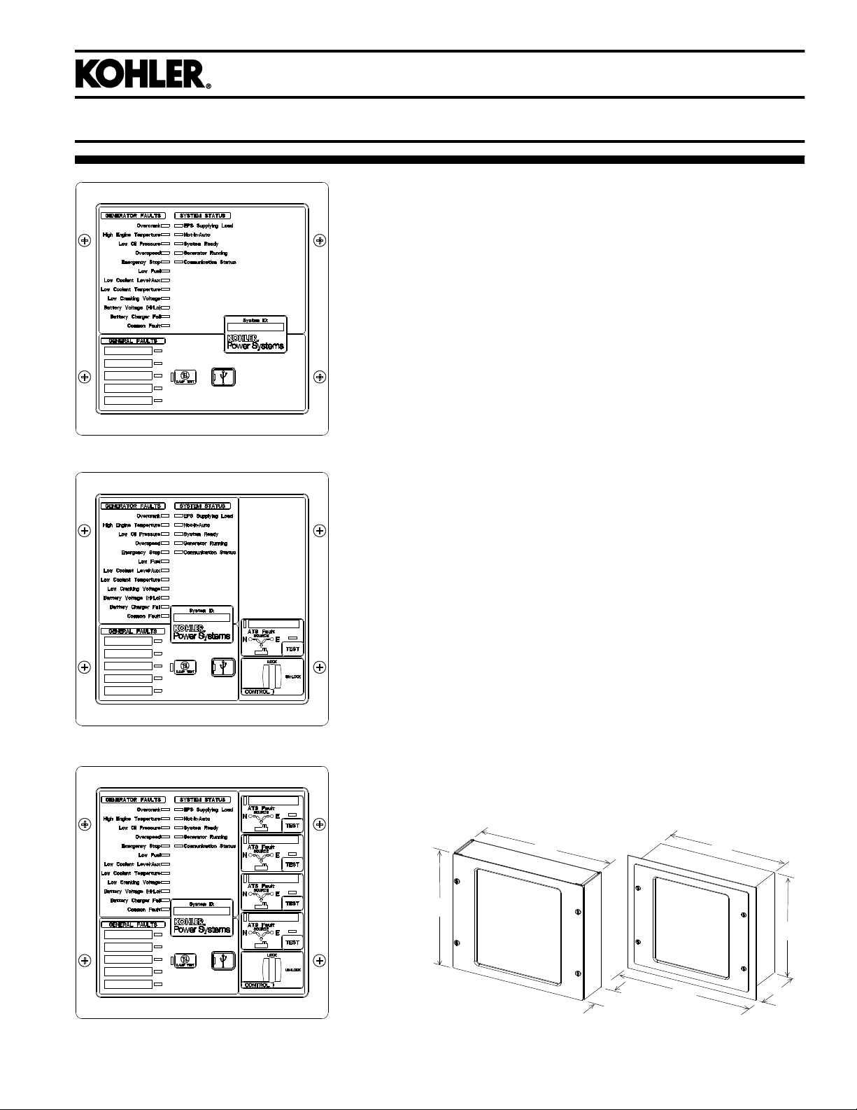
RSA III
RSA III with a Single ATS Control
Industrial Generator Set Accessories
Remote Serial Annunciator III (RSA III)
Remote Serial Annunciator III (RSA III)
for Kohlerr Controllers
D Monitors the generator set equipped with one of the following
controllers:
APM402 Decision-Makerr 3000
APM603 Decision-Makerr 3500
APM802 Decision-Makerr 6000
Decision-Makerr 3+ Decision-Makerr 8000
Decision-Makerr 550 KPC 1000
D Allows monitoring of the common alarm, remote testing of the
automatic transfer switch, and monitoring of the normal/
emergency source for up to four ATS with any of the following
controllers:
Decision-Makerr MPACr 750, 1200, and 1500
MPACr 1000 and 1500
D Configuration via a personal computer (PC) software.
D Writable surfaces (white boxes in illustrations) for user-defined
selections.
D Uses Modbusr RTU protocol.
D Controller connections:
RS-485 for serial bus network
USB port. Connect a personal computer and use Kohlerr
SiteTecht software to view events and adjust settings. *
12-/ 24-volt DC power supply
120/208 VAC power supply (available accessory)
D Meets the National Fire Protection Association Standard
NFPA 110, Level 1.
Dimensions
D Dimensions—W x H x D, mm (in.).
Surface Mounted:
203 x 203 x 83 (8.0 x 8.0 x 3.3)
Flush Mounted (Inside Wall):
203 x 203 x 76 (8.0 x 8.0 x 3.0)
Flush mounting plate W1: 254 (10.0)
* SiteTecht software is available to Kohler authorized distributors and
dealers.
Modbusr is a registered trademark of Schneider Electric.
RSA III with Four ATS Controls
H
G6-139 4/19c
W
D
Surface Mounted Flush Mounted
W1
W
H
D
Page 2
System
Fault and Status Conditions Fault LEDs Fault Horn
Overcrank Shutdown Red On Red Off Green
High Engine Temperature Warning * Yellow On Red Green Green
High Engine Temperature Shutdown Red On Red Off Green
Low Oil Pressure Warning * Yellow On Red Green Green
Low Oil Pressure Shutdown Red On Red Off Green
Overspeed Shutdown Red On Red Off Green
Emergency Stop * Red On Red Off Green
Low Coolant Level/Aux. Shutdown Red On Red Off Green
Low Coolant Temperature * Yellow On Red Off Green
Low Cranking Voltage Yellow On Red Off Green
Low Fuel—Level or Pressure * Yellow On Red Green or Off Green
Not-In-Auto Red On Red Green or Off Green
Common Fault Red On Green Green or Off Green
Battery Charger Fault (1) * Yellow On Red Green or Off Green
Battery Charger Fault (2) * Yellow On Green Green or Off Green
High Battery Voltage * Yellow Off Green Green or Off Green
Low Battery Voltage * Yellow Off Green Green or Off Green
User Input #1 (Warning) Yellow Off Green Green or Off Green
User Input #1 (Shutdown) Red On Green Off Green
User Input #2 (Warning) Yellow Off Green Green or Off Green
User Input #2 (Shutdown) Red On Green Off Green
User Input #3 (Warning) (1) [
User Input #3 (Shutdown) (1) [
User Input #4 (Warning) (1) Y ellow Off Green Green or Off Green
User Input #4 (Shutdown) (1) Red On Green Off Green
User Input #5 (Warning) (1) Y ellow Off Green Green or Off Green
User Input #5 (Shutdown) (1) Red On Green Off Green
EPS Supplying Load Yellow Off Green Green Green
Communications Status (Fault mode) — Off Green or Red Green or Off Red
ATS Fault (RSA III with ATS Controls only) Red On Red or Yellow Green or Off Green
Green LEDs appear as steady on when activated.
Yellow LEDs slow flash when activated except steady on with EPS supplying load and high battery voltage.
Red LEDs slow flash when activated except fast flash with loss of communication and not-in-auto.
Yellow Off Green Green or Off Green
Red On Green Off Green
Ready LED
Generator
Running LED
Communication
Status LED
Specifications
D LED indicating lights for status, warning, and/or shutdown.
D Power source with circuit protection: 12- or 24-volt DC
D Power source with120/208 VAC, 50/60 Hz adapter (option)
D Power draw: 200 mA
D Humidity range: 0% to 95% noncondensing
D Operating temperature range: - 20Cto+70C
(- 4F to +158F)
D Storage temperature range: - 40Cto+85C
(- 40F to +185F)
D Standards:
d NFPA 110, level 1
d UL 508 recognized
d CE directive
d NFPA 99
d ENS 61000- 4- 4
d EN6II-4-4 fast transient immunity
D RS-485 Modbusr isolated port @ 9.6/19.2/38.4/57.6 kbps
(default is 19.2 kbps)
D USB device port
D NEMA 1 enclosure
(1) All generator set controllers except Decision-Makerr 3+ controller.
(2) Decision-Makerr 3+ controller only.
* May require optional kit or user-provided device to enable function and
LED indication.
[ Digital input #3 is factory-set for high battery voltage on the
Decision-Makerr 3+ controller.
Modbusr is a registered trademark of Schneider Electric.
ATS Controls (RSA III with ATS controls only)
D ATS position LED (normal or emergency)
D Power source indicator LED (normal or emergency)
D ATS fault LED
D Key-operated lock/unlock switch for Test feature
D Test pushbutton
NFPA Requirements
D NFPA 110 compliant
D Engine functions:
d High battery voltage warning *
d High engine temperature shutdown
d High engine temperature warning *
d Low battery voltage warning *
d Low coolant level/aux. shutdown
d Low coolant temperature warning *
d Low cranking voltage
d Low fuel warning (level or pressure) *
d Low oil pressure shutdown
d Low oil pressure warning *
d Overcrank shutdown
d Overspeed shutdown
D General functions:
d Audible alarm silence
d Battery charger fault *
d Lamp test
d Master switch not-in-auto
G6-139 4/19c
Page 3

Fault and Status LEDs and Lamp Test Switch
Alarm Horn. Horn sounds giving a minimum 90 dB at 0.1 m
(0.3 ft.) audible alarm when a warning or shutdown fault
condition exists except on high/low battery voltage or EPS
supplying load.
Alarm Silenced. Red LED on lamp test switch lights when
alarm horn is deactivated by alarm silence switch.
Alarm Silence Switch. Lamp test switch quiets the alarm
during servicing. The horn will reactivate upon additional faults.
ATS Fault. Red LED lights when ATS fails to transfer.
Battery Charger Fail. LED lights if battery charger
malfunctions. Requires battery charger with alarm contact.
Battery Voltage Hi/Lo. LED flashes if battery or charging
voltage drops below preset level. LED lights steady if battery
voltage exceeds preset level.
Common Fault. LED lights when a single or multiple
common faults occur.
Communication Status. Green LED lights indicating
annunciator communications functional. Red LED indicates
communication fault.
EPS Supplying Load. LED lights when the Emergency Power
System (EPS) generator set is supplying the load (APM402,
APM603, APM802, and Decision-Makerr 550, 3000, 3500,
6000, and 8000 controllers) or when transfer switch is in the
emergency position (Decision-Makerr 3+ controller).
Emergency Stop. LED lights and engine stops when
emergency stop is made. May require a local emergency
stop switch on some Decision-Makerr 3+ controllers.
Generator Running. LED lights when generator set is in
operation.
High Engine Temperature. Red LED lights if engine has shut
down because of high engine coolant temperature. Yellow
LED lights if engine coolant temperature approaches shutdown
range. Requires warning sender on some models.
Lamp Test (Switch). Switch tests all the annunciator indicator
LEDs and horn.
Low Coolant Level/Aux. LED lights when engine coolant level
is below acceptable range on radiator-mounted generator sets
only. When used with a Decision-Makerr 3+ controller, the LED
indicates low coolant level or an auxiliary fault shutdown.
Requires user-supplied low coolant level switch on remote
radiator models.
Low Coolant Temperature. LED lights if optional engine block
heater malfunctions and/or engine coolant temperature is too
low. Requires prealarm sender on some models.
Low Cranking Voltage. LED lights if battery voltage drops
below preset level during engine cranking.
Low Fuel (Level or Pressure). LED lights if fuel level in tank
approaches empty with diesel models or fuel pressure is low on
gas models. Requires customer-supplied switch.
Low Oil Pressure. Red LED lights if generator set shuts down
because of insufficient oil pressure. Yellow LED lights if engine
oil pressure approaches shutdown range. Requires warning
sender on some models.
Not In Auto. LED lights when the generator set controller is not
set to automatic mode.
Overcrank. LED lights and cranking stops if engine does not
start in either continuous cranking or cyclic cranking modes.
Overspeed. LED lights if generator set shuts down because of
overspeed condition.
System Ready. Green LED lights when generator set master
switch is in AUTO position and the system senses no faults.
Red LED indicates system fault.
User-Defined Digital Inputs #1- #5. Monitors five digital
auxiliary inputs (can be configured as warnings or shutdowns).
User-defined digital inputs are selected via the RSA III master
for local
digital input can be assigned via PC using SiteTecht setup
software.
or remote (generator set or ATS). The user-defined
G6-139 4/19c
Page 4

Accessories
- Power source adapter kit 120/208 VAC, 50/60 Hz.
- Modbusr/Ethernet converter GM41143-KP2 for serial to
Ethernet communication.
- Communication module GM32644-KA1 or GM32644-KP1 is
required with Decision-Makerr 3+ controllers.
Modbusr is a registered trademark of Schneider Electric.
KOHLER CO., Kohler, Wisconsin 53044 USA
Phone 920-457-4441, Fax 920-459-1646
For the nearest sales and service outlet in the
US and Canada, phone 1-800-544-2444
KOHLERPower.com
Availability is subject to change without notice. Kohler Co. reserves the
right to change the design or specifications without notice and without any
obligation or liability whatsoever. Contact your local Kohlerr generator
set distributor for availability.
DISTRIBUTED BY:
2014, 2016, 2018, 2019 by Kohler Co. All rights reserved.
G6-139 4/19c
 Loading...