

Page 1
Original Issue Date: 12/04
Model: RDT, HDT, and KSS-J Automatic Transfer Switches
Market: ATS
Subject: Programmable Exerciser Kits GM47597-KA1, -KA2, KA3, -KP1, -KP2,
and -KP3; GM48913; GM48919, and GM64108
(GM38798-KA1, -KA2, KP1, KP2, discontinued*)
TT-1403 4/16c
INSTALLATION INSTRUCTIONS
Introduction
Use the Programmable Exerciser Kit with the following
transfer switch models:
D RDT
D HDT
D KSS-J with Decision-Makerr MPAC 750 Controller
Service kits are also available to replace the exercise
timer on transfer switches equipped with S340 controls.
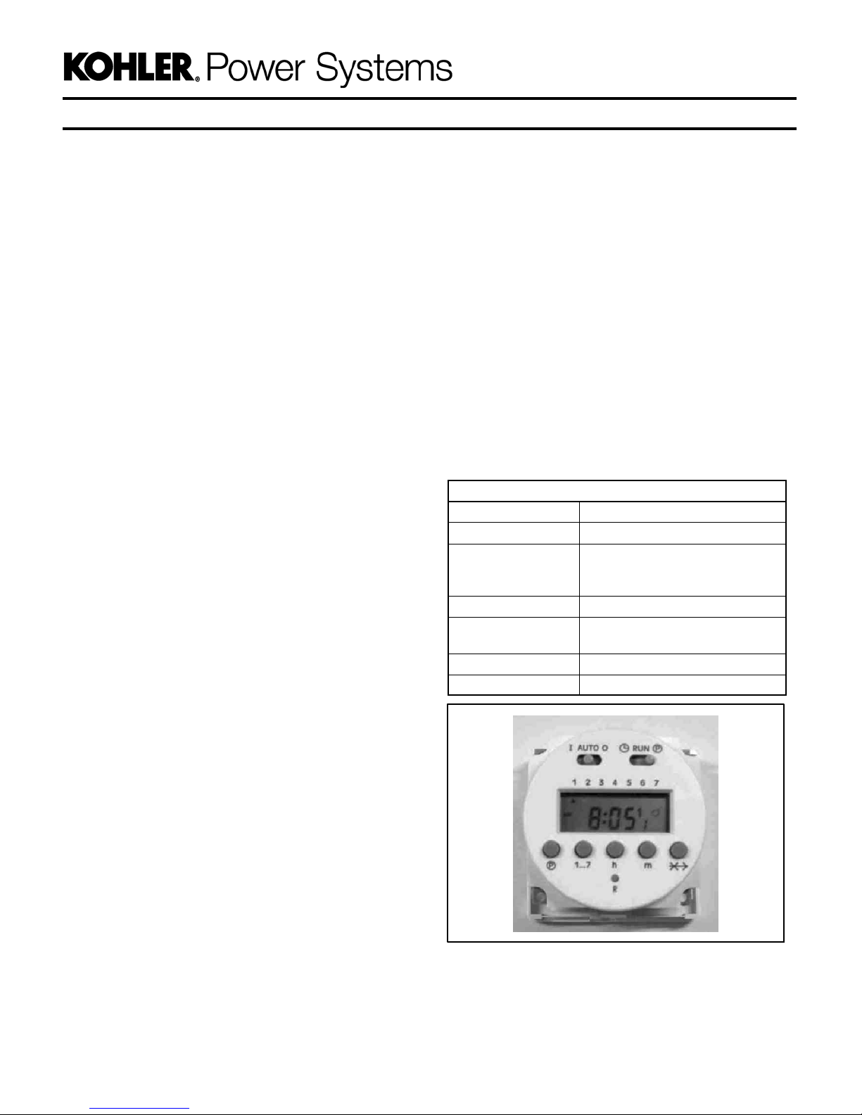
Figure 1 shows the programmable exerciser timer. See
Figure 3 through Figure 5 for illustrations of installed
exerciser timers.
Use the programmable exerciser kit to schedule
generator set exercise runs in addition to the weekly or
biweekly exercise set through the ATS controls. The
programmable exerciser kit can also be used for peak
shaving by scheduling the system to start the generator
set and transfer the load at selected times and days.
Optional Accessory Board GM38796-KA1 or -KP1 is
required for connection and operation of the
programmable exerciser kit on Model RDT transfer
switches.
Timer Features
D 24 hour/7 day timing combined
D 8 on/off operations daily, up to 56 switching (on or off)
cycles per week
D 5 year lithium battery for backup power
D 24 hour display (military time or AM/PM)
D Manual override
D Skip a day feature
Programmable Timer Specifications
Switching SPDT
Switch rating 16 A @ 45C; 10 A @ 55C
Supply voltage 120VAC, 50/60 Hz (GM60427)
Rated power 3.5 VA
Operating
temperature range
Connections 6.3 x 0.8 tab terminals
Shortest switch time 1 minute
240VAC, 50/60 Hz (GM64028)
5-year lithium backup battery
-- 1 0 Cto55C
(--14F to 131F)
The programmable exerciser kits include
programmable timer GM64027 or GM64028, mounting
hardware, and connecting leads as required.
Read the entire installation procedure and compare the
kit parts with the parts list at the end of this publication
before beginning installation. Perform the steps in the
order shown. The installation and wiring must comply
with the National Electrical Code and applicable local
codes.
* Discontinued kits. See page 13 for instructions.
Figure 1 Programmable Exerciser GM64027 (120V)
and GM64028 (240V)
Page 2
Safety Precautions
Observe thefollowing safetyprecautions whileinstalling
the kit.
DANGER
WARNING
Accidental starting.
Can cause severe injury or death.
Disconnect the battery cables before
working on the generator set.
Remove the negative (--) lead first
when disconnecting the battery.
Reconnect the negative (--) lead last
when reconnecting the battery.
Disabling the generator set. Accidental starting can
cause severe injury or death. Before working on the
generator set or connected equipment, disable the generator
set as follows: (1) Move the generator set master switch to the
OFF position. (2) Disconnect thepower to the battery charger.
(3) Remove the battery cables, negative (--) lead first.
Reconnect the negative (--) lead last when reconnecting the
battery. Follow these precautions to prevent starting of the
generator set by an automatic transfer switch, remote
start/stop switch, or engine start command from a remote
computer.
(Decision-Makerr 3+ and 550 Generator Set Controllers)
Disabling the generator set. Accidental starting can
cause severe injury or death. Before working on the
generator set or equipment connected to the set, disable the
generator set as follows: (1) Press the generator set off/reset
button to shut down the generator set. (2) Disconnect the
power to the battery charger, if equipped. (3) Remove the
battery cables, negative (--) lead first. Reconnect the negative
(--) lead last when reconnecting the battery. Follow these
precautions to prevent the starting of the generator set by the
remote start/stop switch.
(RDC, DC, RDC2, DC2, Decision-Makerr 3000, 3500 and
6000 Generator Set Controllers)
DANGER
Hazardous voltage.
Will cause severe injury or death.
Disconnect all power sources before
opening the enclosure.
Hazardous voltage.
Will cause severe injury or death.
Only authorized personnel should
open the enclosure.
Short circuits. Hazardous voltage/current can cause
severe injury or death. Short circuits can cause bodily injury
and/or equipment damage. Do not contact electrical
connections with tools or jewelry while making adjustments or
repairs. Remove all jewelry before servicing the equipment.
NOTICE
Foreign material contamination. Cover the transfer switch
during installation to keep dirt, grit, metal drill chips, and other
debris out of the components. Cover the solenoid mechanism
during installation. After installation, use the manual operating
handle tocycle thecontactor toverify that it operates freely. Do
not use a screwdriver to force the contactor mechanism.
1 Kit Application Notes
Figure 2 lists the available programmable exerciser kits
and their applications. Kits include the programmable
exerciser timer and mounting hardware.
To replace the older style timer GM39330 on the
200 Amp service entrance rated model RDT, service kit
GM64108 is required. The service kit includes a retrofit
mounting panel that is required for timer replacement on
the 200 Amp service entrance rated Model RDT only.
Service kitsare also availablefor exerciser replacement
on transfer switches equipped with S340 controls.
Kit Number Application
GM47597-KP2 100--200 Amp Model RDT
GM47597-KP1 400 Amp Model RDT;
GM47597--KP3
GM48913 Service Kit for S340 Controls,
GM48919 Service Kit for S340 Controls,
GM64108 Service Kit for 200 Amp RDT SE *
GM38798-KA1,
-KA2, -KP1, -KP2
* SE = Service Entrance Model
200 and 400 Amp Model RDT SE *
Model KSS-J with Decision-Makerr
MPAC 750 Controller
120 VAC
240 VAC
(replaces timer GM39330)
Kits with timer GM39330.
Discontinued; see page 13.
2 TT-1403 4/16
Figure 2 Programmable Exerciser Kit Application
Page 3
2 Installation Procedure
2.1 Mounting, 100--200 Amp Model RDT
Note: For factory-installed exerciser kits, proceed to
section 5.
1. Disable the generator set to prevent accidental
starting:
a. Shutdown the generator set by either moving
the generator set master switch to OFF or by
pressing the OFF/RESET button on the
generator set controller.
b. Disconnect power to the battery charger, if
equipped.
c. Disconnect the generator set engine starting
battery, negative (--) lead first.
2. Disconnect power to the transfer switch before
opening the ATS enclosure.
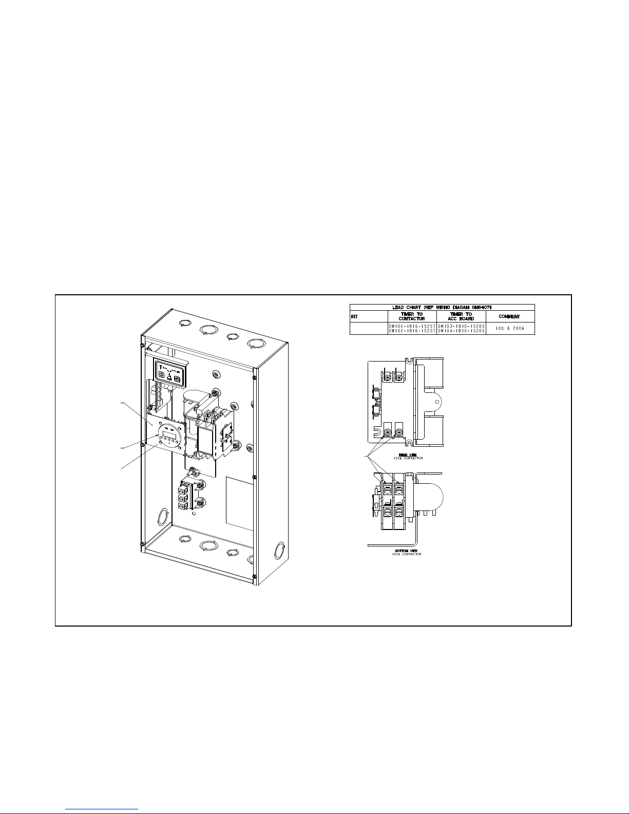
SeeFigure3.
1. Install timer mounting bracket GM64057 over the
controller bracket as shown in Figure 3. Use the
existing controller bracket nuts to secure the timer
mounting bracket to the bottom 2 studs.
2. Insert the timer through the opening in the bracket.
Secure the timer to the four standoffs using four
mounting screws X-49-2 provided with the kit.
3. Proceed to the Wiring Section for timer
connections.
Note: For 100 Amp models: Insert the lead ring
terminals through the slot under the bus and
under the flat washer on the load lug. See
Figure 3.
GM47597-- KP2
GM47597
1
2
3
1. Mounting bracket GM64057
2. Timer GM64028
Figure 3 Mounting, 100--200 Amp Model RDT
4
GM38798
3. Screws X-49-2 (qty. 4)
4. Load lugs. See step 3 and note, above.
TT-1403 4/16 3
Page 4
2.2 Mounting, 400 Amp Model RDT,
Service Entrance Rated 200 Amp or
400 Amp Model RDT
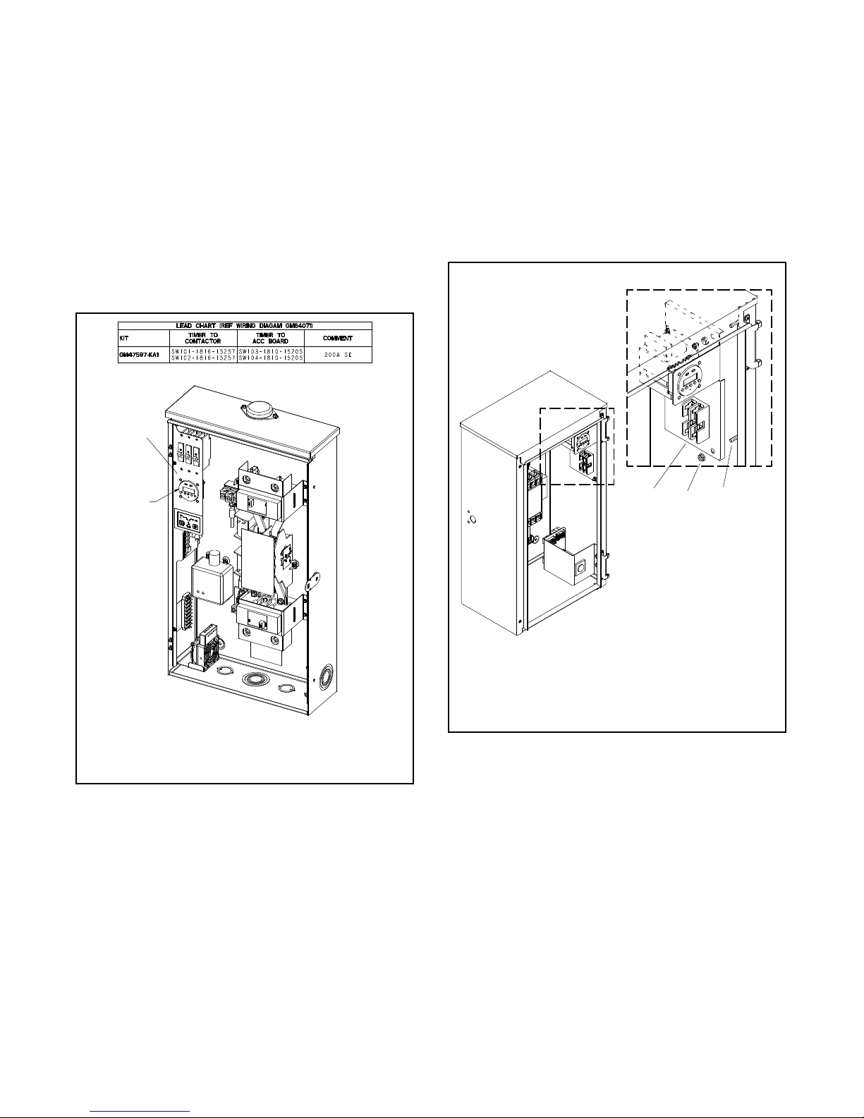
SeeFigure4.
1. Replace the existing mounting bracketwith bracket
GM64055 provided with the kit. See Figure 4.
2. Insert the timer through the opening in the bracket.
Secure the timer to the four standoffs using four
mounting screws X-49-2 provided with the kit.
3. Proceed to the Wiring Section for timer
connections.
1
2.3 Mounting, Models KSS-J with
Decision-Makerr MPAC 750 Controller
1. Align the mounting holes on the timer bracket
GM89060 with the two mounting studs on the
inside of the transfer switch box. See Figure 5.
1. Secure the timer kit to the studs with the two
X-6210-2 nuts provided with the kit. See Figure 5.
2. Proceed to the Wiring Section 3.2 for timer
connections.
2
GM47597
1. Bracket GM64055
2. Timer GM64028 with screws X-49-2 (qty. 4)
Figure 4 Mounting, 400 Amp Model RDT or 200
Amp and 400 Amp Service Entrance Rated
Model RDT
1
2
1. Bracket GM89060
2. Nut X-6210-2 (qty. 2)
3. Mounting Stud
Figure 5 Mounting, Models KSS-J with
Decision-Makerr MPAC 750
3
GM46745
4 TT-1403 4/16
Page 5
2.4 Service Kit GM64108, Retrofit Timer
Replacement Kit for the Service
Entrance Rated 200 Amp Model RDT
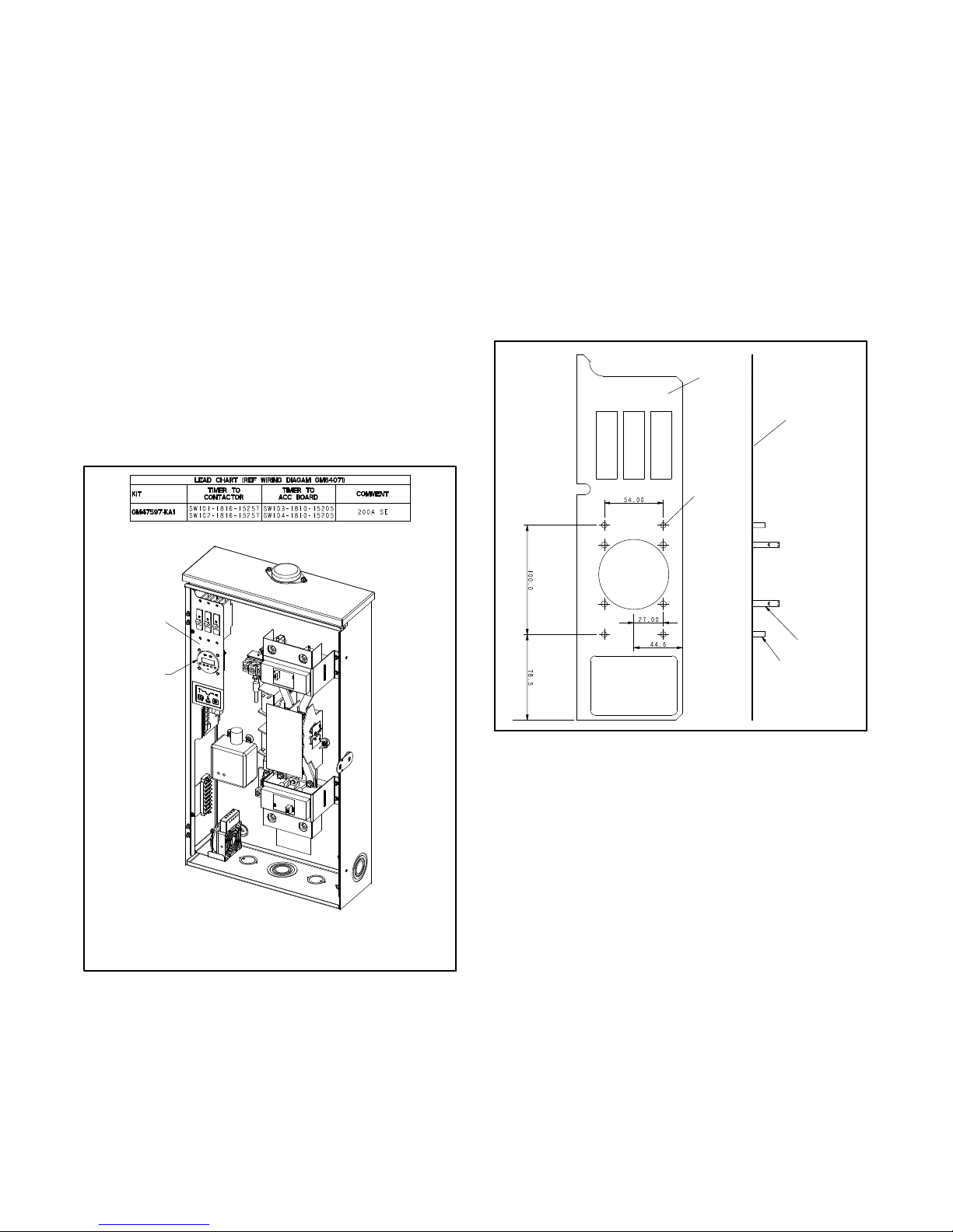
See Figure 6 and Figure 7. Use Service Kit GM64108 to
replace an old style timer GM39330 with timer
GM64028. The service kit includes retrofit mounting
panel GM64074.
from metal drill chips. Drill four 1/4 inch diameter
holes through the existing mounting bracket at the
marked locations.
2. Align and insert the mounting studs on the retrofit
mounting bracket through the newly drilled holes
on the existing mounting bracket. Thread nuts
X-6210-1 onto the mounting studs to secure. See
Figure 6 and Figure 7.
Tools Required:
D Electric drill with 1/4 in. chuck (minimum)
D 1/4 inch dia. drill bit
NOTICE
Foreign material contamination. Cover the transfer switch
during installation to keep dirt, grit, metal drill chips, and other
debris out of the components. Cover the solenoid mechanism
during installation. After installation, use the manual operating
handle tocycle thecontactor toverify that it operates freely. Do
not use a screwdriver to force the contactor mechanism.
2
1
3. Secure the timer tothe four standoffsusing the four
mounting screws X-49-2 provided with the kit.
4. Proceed to the Wiring Section for timer
connections.
1
1
2
3
2
Figure 7 Retrofit Mounting Panel GM64074
GM47597
1. Timer GM64028 with screws X-49-2 (qty. 4)
2. Mounting bracket GM64074 with nuts X-6210-1 (qty. 4)
Figure 6 Retrofit Timer Replacement Service Kit
GM64108 for Service Entrance-Rated 200
Amp Model RDT
1. Using the dimensions in Figure 7 or retrofit panel
GM64074 as a guide, mark four holes on the
existing mounting bracket at the locations of the
four studs on the retrofit panel. Cover the
components inside the enclosure to protect them
TT-1403 4/16 5
Page 6

3 Wiring
3.1 RDT Models
DANGER
Hazardous voltage.
Will cause severe injury or death.
Disconnect all power sources before
opening the enclosure.
Short circuits. Hazardous voltage/current can cause
severe injury or death. Short circuits can cause bodily injury
and/or equipment damage. Do not contact electrical
connections with tools or jewelry while making adjustments or
repairs. Remove all jewelry before servicing the equipment.
Wiring must comply with the National Electrical Code
and applicable local codes.
Note: Check that the supply voltage matches the
voltage marked on the unit. Wiring to incorrect
voltage will void the warranty.
1
1. Verify that power has been disconnected as
described in Section 2, Installation Procedure.
2. Use the leads supplied with the kit to connect the
timer according to the wiring diagrams. See
Figure 8.
Note: For 100 Amp models: Insert the lead ring
terminals through the slot under the bus and
under the flat washer on the load lug. See
Figure 3.
2
1. Accessory Board
2. DIP - Switches
3. Timer
4. Contactor (200Amp Shown)
Figure 8 Wiring Diagram for RDT Models
3
4
GM64071
6 TT-1403 4/16
Page 7

3.2 KSS-J Models with Decision-Makerr
MPAC 750 Controllers
1. Verify that power has been disconnected as
described in Section 2, Installation Procedure.
2. Use harness leads GM91325,supplied, to connect
the exercise kit according to the wiring diagram in
Figure 10. Connect the timer to the controller
(leads 103 and 104) and connect the fuse block to
the contactor (leads LA and LC). Use piggyback
terminals 233704 at the contactor if needed.
3. Connect the transformer to supply the correct
voltage to the timer. Configure the primary and
secondary transformer connections for the
corresponding system voltage. See Figure 9 and
Figure 11.
Transformer Connections
System Voltage
208 H1, H2 X1, X4
220--240 H1, H2 X1, X3
380--416 H1, H3 X1, X3
480 H1, H4 X1, X3
Primary Secondary
Figure 9 Transformer Wiring Configuration Chart
2
3
1
1. Decision- Makerr MPAC 750 Controller
2. Harness GM91325
3. Timer GM64027
4. Fuse blocks X-6129-2 and X-6129-4
5. Contactor
6. Transformer GM40071
4
5
6
Figure 10 Wiring Diagram for KSS-J Models with Decision-makerr MPAC 750 Controller
2
GM91312
1
1. Primary Transformer
Connections
2. Secondary Transformer
Connections
Figure 11 Diagram Detail, Transformer Wiring Configuration (208 V shown; see Figure 9 for other voltages)
TT-1403 4/16 7
GM91312
Page 8

4 Service Kits GM48913 and
GM48919
Use the service kit GM48913 (120VAC) or
GM48919 (240VAC) to replace failedexercise timerson
transfer switches equipped with S340 controls. The
service kits include the exercise timer GM64027, timer
enclosure GM64054, and a DIN rail for timer mounting.
See Figure 12 and Figure 13.
GM64027
Figure 12 Timer with Enclosure
5 Setup
After connecting the wiring leads, the controllers must
be set for loaded or unloaded exercise. Follow the
specific instructions below for either the RDT or KSS-J
model transfer switches.
Note: Changing the type of exercise (loaded or
unloaded) that is run by the exercise timer does
not affect the type of exercise that is set by the
transfer switch controller.
5.1 Setup for RDT Models
On RDT model transfer switches, the exercise timer
must be set manually to run either loaded or unloaded
exercises. Set DIP switch #2 on the Accessory Board to
select loadedor unloaded exercise runs. SeeFigure 14.
See Figure 8 for the location of the DIP switches on the
accessory board.
D Set DIP switch #2 to the OFF position to run the
generator set without transferring the load, or
D Set DIP switch #2 to the ON position to start the
generator set and transfer the load during exercise
runs. For peak shave applications, set the DIP switch
to the ON position.
OFF
DIP Switch
2 Loaded Exercise Unloaded Loaded
(open)
ON
(closed)
1 2
GM64087
1. To power source:
120 VAC (GM64027 timer)
240 VAC (GM64028 timer
2. Engine start connection
Figure 13 Wiring Diagram for Service Kits GM48913
and GM48919
Figure 14 Accessory Board DIP Switch Setting
1
2
1. Accessory
Board
2. DIP
Switches
GM64027
Figure 15 Detail, Dip Switch Location
8 TT-1403 4/16
Page 9

5.2 Setup for KSS-J with Decision-Makerr
MPAC 750
On KSS-J model transfer switches, use SiteTecht
software to change the default setting (unloaded) for
exercises that are run by the exercise timer. Kohler
SiteTech is available to Kohler authorized distributors
and dealers. For detailed information on using SiteTech
software, see the SiteTech operation manual, TP-6701.
Note: On the MPAC 750 controller, the default setting
for the exercise timer will be unloaded.
Note: The exerciser timer uses the remote test feature
to provide the exerciser timer functionality. If
necessary, an exercise started by the
programmable exerciser can be stopped locally
by pressing and holding the TEST button on the
MPAC 750 controller for about two seconds.
1. Reconnect power as described in Section 6.
2. Use a USB cable to connect the Decision-Makerr
MPAC 750 controller to your personal computer.
3. Launch the SiteTech software.
4. Select Prog. Inputs at the top of the screen.
5. For Mainboard Input 1, select Remote Test from
the drop-down menu. See Figure 16.
6. Select Parameters at the top of the screen.
7. Scroll down to Accessory Setup A1 and click on
the arrow to expand the menu. See Figure 17.
8. Find Accessory Setup A1 Remote Test Load in
the list and select either Loaded orUnloaded from
the drop-down menu in the second column.
9. Select Apply Changes from the top menu to set
the changes and complete the procedure.
Figure 17 SiteTech Software, Programming Exercise
Timer
Figure 16 SiteTech Software, Programming Exercise
Timer
TT-1403 4/16 9
Page 10

6 Reconnect Power
7.1 Setting the timer
DANGER
Hazardous voltage.
Will cause severe injury or death.
Only authorized personnel should
open the enclosure.
Short circuits. Hazardous voltage/current can cause
severe injury or death. Short circuits can cause bodily injury
and/or equipment damage. Do not contact electrical
connections with tools or jewelry while making adjustments or
repairs. Remove all jewelry before servicing the equipment.
Reconnect power to the system.
1. Install the transfer switch enclosure door(s).
2. Reconnect power to the transfer switch.
3. Reconnect the generator set engine starting
battery, negative (--) lead last.
4. Reconnect power to the battery charger, if
equipped.
7 Programming and Operation
The timer provides flexible timing for daily and/or weekly
programming. The single-channel timer combines
24 hour/7 day timing.
Each exerciseperiod requiresseparate programming of
the ON and OFF time. Up to 8 on/off operations are
allowed for each day for a total of up to 56 switching
cycles per week.
Be sure to program an off cycle after every on cycle.
The minimum time setting is 1 minute.
Setting the current time and day
1. Slide RUN switch to left symbol of clock face.
2. Press the 1.7 button until the arrow points to
current day (1=Monday, 2=Tuesday, etc.). Press
the h (hour) and m (minute) buttons to set the
current time. Pay attention to the AM/PM indicator.
The PM indicator shows from noon to 11:59 p.m.
3. Slide the RUN switch to run. The clock colon
between the hours and minutes blinks when the
clock is running.
1
14
2
3
DANGER
Hazardous voltage.
Will cause severe injury or death.
Only authorized personnel should
open the enclosure.
Short circuits. Hazardous voltage/current can cause
severe injury or death. Short circuits can cause bodily injury
and/or equipment damage. Do not contact electrical
connections with tools or jewelry while making adjustments or
repairs. Remove all jewelry before servicing the equipment.
Remove the transfer switch enclosure door(s)to access
the programmable exerciser. Do not contact electrical
connections when programming the exerciser.
Note: A lithium battery provides 5 year backup power.
The timer can be programmed after installation
before reconnecting power to the transfer switch.
13
12
1. AUTO switch
2. RUN switch
3. Number 1 indicates
single channel timer
4. Switch on indicator
(light bulb symbol)
5. Cycle number indicator
6. Skip indicator
7. Skip a day button
10
8. Minutes button, m
9. Hour button, h
10. Reset button
11. 1...7 day selection
button
12. Program button
13. AM/PM indicators
14. Day 1--7 indicators
Figure 18 Timer Switches and Display
4
5
6
tt1403
78911
10 TT-1403 4/16
Page 11

7.2 Programming the Exercise Cycles
Use the procedures in the following sections to program
up to 8 on/off events for each day of the week.
Note: After each ON cycle, be sure to program a
corresponding OFF cycle for the same days of
the week.
After all exercise cycles have been programmed, slide
the RUN switch to the RUNposition. The clock colon will
blink.
7.2.1 Day Selection
For each on or off cycle, you will need to set the day or
days of the week. To save time you can set up each
on/off cycle for one day, Monday through Friday,
weekends only, all days except Sunday, or the entire
week. This can save a lotof time when programming the
on and off cycles.
1. Slide the RUN switch to P.
2. Press the 17 button seven times and notice a
single arrow will move in steps below the 1--7
numbers, indicating the individual days of the week
3. Press the 17 button again to see days 1 to 5
highlighted with arrows (Monday through Friday).
4. Press 17 againto seearrows highlighting 6 and 7
(weekends).
5. Press 17 again to see arrows highlighting all
days except Sunday.
6. Press 17 again to see arrows highlighting all
days of the week.
7.2.2 Programming an ON cycle
1. Slide the RUN switch to P. The lower number 1
indicates thisis the first switch cycleand a bulb icon
indicates a switch on condition (circuit closes).
Note: Odd numbers indicate a switch-on cycle.
7.2.3 Programming an OFF cycle
1. Slide the RUN switch to P. Press the P button. The
switch cycle number changes to 2 and the bulb
blinks, indicating switch-off (circuit opens).
Note: Even numbers indicate a switch-off cycle.
2. Press the 1...7 button until the arrows point to the
selected day(s) you want this OFF cycle to occur.
3. Press h and m buttons to select the switch-off time.
To program another exercise cycle, press the lower P
button to advance to the next cycle and return to step 2
of Section 7.2.2.
After programming the on and off cycles, slide the RUN
switch to the RUN position. The clock colon will blink.
7.2.4 Setting error
If EEE appears, a setting error exists. The switch cycle
number in error is shown.
1. Slide set switch to P.
2. Press P button until the cycle with the error is
shown. Review this and the nextsetting andcorrect
the error.
3. Slide the set switch to RUN.
7.2.5 Clear any setting
1. Slide the RUN switch to P.
2. Press the lower P button to move to the switch on
cycle you want to clear.
2. Press the 1....7 button until arrowspoint to selected
day(s) youwant thisON cycleto occur. See Section
7.2.1, Day Selection, for instructions to choose
days of the week.
3. Press the h and m buttons to show the desired
switch-on time, noting the AM/PM indicator.
TT-1403 4/16 11
3. Press the P and X—> (skip) buttons
simultaneously and hold until the time display
shows 00:00. Repeat for the corresponding switch
off cycle. This on/off cycle is now inactive.
7.2.6 Clear all settings
To erase all settings, press R.
Page 12

7.3 Operation
Note: Setting the override to ON ( I ) will signal the
generator set to run continuously.
7.3.1 Autorun mode
1. Set the time and day and desired switch cycles.
2. Slide set switch to RUN and mode switch to AUTO.
Switching will begin with the next switch-on set
time.
7.3.3 To switch the override OFF
Slide the mode switch to 0. The switch remains off
indefinitely ( circuit open).
Note: The generator set will not exercise on schedule if
the override is set to OFF (0).
7.3.2 To switch the override ON
Slide mode switch to I. The switch remains on
indefinitely (circuit closed).
7.3.4 Skip a cycle
In automatic run mode, press the X—> button to skip the
next program.
8 Programming Worksheet
Use the following worksheet to plan on and off switching cycles for each exercise run. Program an off cycle after each
on cycle.
Cycle
Ex. 1 On AM 7 20 1--5
Ex. 2 Off AM 7 50 1--5
1
2
3
4
5
6
7
8
9
10
11
12
13
On/Off AM/PM h m Day(s)
14
15
16
12 TT-1403 4/16
Page 13

9 Exerciser GM39330
The older styleprogrammable timer GM39330 shown in
Figure 19 is no longer available. Instructions for the
GM39330 timer are provided in this section for
reference.
9.1 Installation Procedure,
Exerciser GM39330
For installed kits (GM38798-KA1 and -KA2), start with
the ATS Setup section and then proceed to the
programming instructions.
1. Disable the generator set to prevent accidental
starting:
a. Disconnect power to the battery charger, if
equipped.
b. Disconnect the generator set engine starting
battery, negative (--) lead first.
2. Disconnect power to the transfer switch before
opening the ATS enclosure.
9.1.1 Mounting
Figure 19 Programmable Exerciser GM39330
(no longer available)
Programmable Exerciser Specifications
Output 1 SPDT relay with dry contacts
Switch rating 16A 277VAC resistive
Supply voltage 208/240VAC, 50/60Hz ;
Power required 4VA
Ambient temperature
range
Connection 1/4 in. quick connects
Accuracy 4 minutes per year
Shortest switch time 1 minute
100 hour capacitor backup of
memory and display
-- 2 8 Cto60C
(--20F to 140F)
10 -- 24 AWG
Figure 20 GM39330 Specifications
The Programmable Exerciser is programmable for
24-hour or 7-day schedules. Follow the instructions in
this document to install (if not factory-installed) and
program the exerciser.
Mount the programmable exerciser on the bracket
provided with the kit as shown in Figure 22.
1. Install the mounting bracket as shown inFigure 22.
2. Insert the exerciser through the opening in the
bracket. With a screwdriver, press down and turn
the outer screws until the flanges are in position to
fasten the unit in the bracket, then release.
3. Insert plugs into the unused holes. See Figure 21.
1
2
1. Outer screws 2. Holes
2
1
Figure 21 Mounting Flanges
TT-1403 4/16 13
Page 14

ACCESSORY BOARD LOCATION
TIMER GM39330
Figure 22 Mounting
DIP SWITCHES
Figure 23 Wiring Diagram
GM38798
(200 A SHOWN)
GM39331
14 TT-1403 4/16
Page 15

9.1.2 Wiring
Wiring must comply with the National Electrical Code
and applicable local codes.
Note: Check that the supply voltage matches the
voltage marked on the unit. Wiring to incorrect
voltage will void the warranty.
9.3 Operating Instructions,
Exerciser GM39330
DANGER
1. Verify that power has been disconnected as
described above.
2. Use the leads supplied with the kit to connect the
exerciser according to the wiring diagram in
Figure 23.
9.2 ATS Setup,
Exerciser GM39330
Set DIP switch #2 on the Accessory Board to select
loaded or unloaded programmed exercise runs. See
Figure 22 and Figure 23 for the location of the DIP
switches on the accessory board.
D Set DIP switch #2 to the OFF position to run the
generator set without transferring the load. See
Figure 24, or
D Set DIP switch #2 to the ON position to start the
generator set and transfer the load during
programmed exercise runs. For peak shave
applications, set the DIP switch to the ON position.
DIP switch #2 does not affect the exercise period that is
set by pressing the Exercise button on the ATS
controller.
Hazardous voltage.
Will cause severe injury or death.
Only authorized personnel should
open the enclosure.
Short circuits. Hazardous voltage/current can cause
severe injury or death. Short circuits can cause bodily injury
and/or equipment damage. Do not contact electrical
connections with tools or jewelry while making adjustments or
repairs. Remove all jewelry before servicing the equipment.
The programmable exerciser must have power
connected in order to set the time and program the unit.
1. Install the transfer switch enclosure door(s).
2. Reconnect power to the transfer switch.
3. Reconnect the generator set engine starting
battery, negative (--) lead last.
4. Reconnect power to the battery charger, if
equipped.
5. Remove the transfer switch enclosure door(s) to
access the programmable exerciser. Do not
contact electrical connections when programming
the exerciser.
OFF
DIP Switch
2 Loaded Exercise Unloaded Loaded
(open)
ON
(closed)
Figure 24 Accessory Board DIP Switch Setting
TT-1403 4/16 15
Page 16

9.3.1 Key Description
See Figure 19 for key locations and Figure 25 for
descriptions of the keys.
Key Description
Setting the Time/Automatic Run Mode Prog.
Prog. Program Mode
Res.* Reset: Clears all programs and time
Select ON or OFF in Prog. Mode, Manual Override in
Run Mode
Select ON or OFF in Prog. Mode, Manual Override in
Run Mode
1h* Manual Daylight Change Key
h Setting the Hour (12:-- -- AM)
m Setting the M inute (12:01 AM)
Day Set Day(s) for time and programs
* Recessed keys; use a pen point to press.
Figure 25 Key Description
9.3.2 LCD Display Elements
The LCD incorporatesa number of different elements to
display various data and information. See Figure 26.
Figure 27 Time Display
9.3.4 Setting the Time
Note: If the h and m keys are held down longer than
2 seconds, the numbers will advance rapidly.
Press and hold the
daylight savings time is in effect, press 1h first).
1. Press h to advance to the current hour (while
holding down the
2. Press m to advance to the current minute (while
holding down the
3. Press Day repeatedly to advance to current day
(while holding down the
key during the following: (If
key).
key).
key).
Figure 26 LCD Display
9.3.3 Selecting AM/PM or Military Time
Note: Before proceeding with setting the time and
programming theunit, press thereset key to clear
all data from the memory.
After pressing reset, the display may show AM (right).
The numberedday symbols willbe flashing onand off. If
the display does not show AM, it is in military time mode
(00:00 to 23:59). To change to AM/PM mode, press and
hold the h key and press the 1h key once. AM will
appear in display. If display is in AM mode and military
mode is desired, press and hold the h key, pressthe 1h
key once.
9.3.5 Manual Daylight Time Changeover
Each year, in the Spring, press 1h to advance the time
an hour. In the Fall, press 1h to set back an hour.
9.4 Programs,
Exerciser GM39330
The Programmable Exerciser will accept up to 20
programs. A program consists of:
D An ON or OFF command
D Time of day (hour and minute)
D Single day or multiple days
Each exercise period requires two programs: one ON
command tostart the generator set, anda separateOFF
command to stop the generator set.
Note: Do not program an ON command without also
programming an OFF command.
A programmed OFF command will not transfer the load
or shut down the generator set if the utility (normal)
power is not available.
16 TT-1403 4/16
Page 17

Multiple on or off events may be programmed. For
example, Program 1 may turn the generator set ON at
10:00 PM Mon.--Fri. Program 2 may turn the generator
set OFF at 10:30 PM Mon.--Fri.
Loaded/unloaded exercise: The setting of DIP switch
#2 onthe Accessory Board determines whetherthe load
is transferred to the generator set during the
programmed exercise r uns. See ATS Setup.
Note: An exercise period that is scheduled by pressing
the Exercise button on the ATS controller is not
affected by the programmable exerciser or the
DIP switch setting.
Programming Notes
D If the days are flashing, it indicates the day of the
week was not set when setting the time. The timer
cannot be programmed unless the day of the week is
entered.
D If the programmed ON time is earlier in the day than
the current time, press
once to turn the timer on.
The timer does not look back to determine if it should
be on or off after programming.
D If 24 hour time control (same schedule every day of
the week) is desired, ignore the the Day key.
When programming is complete, snap the clear plastic
cover over the exerciser. Replace the transfer switch
enclosure door(s).
9.4.1 Programming 24 Hour or 7 Day
Schedules
It is helpful to write out the program schedules before
beginning. See Figure 28 on page 17.
The current time of day and day of week must be set
before programming. See Setting the Time.
Prog On/Off h m Day(s)
1 On 7am 20 Mon., Tue., Wed., Thurs., Fri.
D If anON or OFF symbol isnot entered, the ON symbol
will flash, and the program will not be accepted.
9.4.2 Day Key Selections
Press Day Key Display Shows Days
0times 1234567 Every day
1time 123456 Monday--Saturday
2times 12345 Monday--Friday
3times 67 Saturday and Sunday
4times 1 Monday
5times 2 Tuesday
6times 3 Wednesday
7times 4 Thursday
8times 5 Friday
9times 6 Saturday
10 times 7 Sunday
Figure 28 Programming Worksheet, Timer GM39330
TT-1403 4/16 17
Page 18

EXAMPLE
9.4.4 Changing A Program
The following example demonstrates how to program
different on and off times. Typically, the generator set
should be exercised once a week.
Program 1: ON at 1:00 AM Monday thru Saturday
Program 2: OFF at 1:30 AM Monday thru Friday
Program 3: OFF at 2:00 AM Saturday
Three programs need to be entered.
Press the Prog. key only once. The display appears as
shown in Figure 29.
Figure 29 Display after Prog. KeyisPressed
Program 1 (ON at 1:00 AM Monday thru Saturday):
Press
Press h key to 01AM
Press m key once to 00
Press Day keyonce 123456isdisplayed
Press Prog. key to enter
key once ON symbol appears
Select the program to be changed with the Prog. key. A
new setof days maybe selected with the Day key just as
in initialprogramming. Hour andminute canbe changed
with the h and m keys. Press Prog.or
new program.
key tostore the
9.4.5 Deleting A Program
To delete only one or a few programs:
1. Press Prog. key until the desired program is
displayed.
2. Press m key to :59 and press once more to blank
out.
3. Press h key to 11PM and press once more to blank
out.
4. Press
and then enter the Run Mode.
Note: Using the reset key will delete ALL programs, the
time of day, and day of the week.
key. Display will flash for several seconds
9.5 Manual Override,
Exerciser GM39330
Program 2 (OFF at 1:30 AM Monday thru Friday):
Press
Press h key to 01AM
Press m key to 30
Press Day keytwotimes 12345isdisplayed
Press Prog. key to enter
Program 3 (OFF at 2:00 AM Saturday):
Press
Press h key to 02AM
Press m key once to 00
Press Day key 9 times until only 6 is displayed
Press Prog. key to enter
Press
key twice OFFsymbol appears
key twice OFFsymbol appears
key to enter
9.4.3 Reviewing Programs
To review the programs at any time, press Prog. key.
Programs willappear inthe order they were enteredwith
repeated presses of the Prog. key. After all programs
have been reviewed, the blank display will appear to
allow entering another program. Another press of the
Prog. key will display the number of free programs
available, such as Fr 16 if 4 programs have been
entered.
9.5.1 Temporary Override
While in the Run Mode, pressing the key once will
reverse the output; ON to OFF or OFF to ON. The
symbol appears in the display to indicate a temporary
override. At the next scheduled switching time,
automatic control resumes, eliminating the override.
Pressing the override key will turn the generator set on
at unprogrammed times. Be sure to press the override
key again to turn the generator set off.
Note: If the override key is not pressed a second time to
turn the unit off, the generator set will run until the
next programmed OFF event.
18 TT-1403 4/16
Page 19

9.5.2 Continuous Override
While in the Run Mode:
D Pressing the key twice will turn the output to ON
permanently.
D Pressing the key three times will turn the output
OFF permanently.
D To terminate a continuous override, press the key
until
appears in the display.
symbol appears in display.
symbol appears in display.
9.6 Troubleshooting,
Exerciser GM39330
PROBLEM: Days are flashing, pressing key turns
output ON and OFF, and pressing any other key does
nothing.
SOLUTION: Time of Day and Day of Week have not
been set. See Setting the Time.
This is the condition after a reset. If the timer is found in
this condition after it has been installed, programmed
and operating for a while, it may indicate that electrical
noise or voltage transients have disrupted the
microprocessor causing a loss of program information.
Contact the factory if the problem persists.
A second but unlikely cause of program loss is a power
failure with the backup capacitor low or dead. Check by
disconnecting power and monitoring how long the
capacitor keeps the time of day in the display. Typically,
the capacitor will maintain the time and programs for 4
days, but not more than 5 days.
PROBLEM: Time of day was set while holding the
key down, but days are still flashing.
SOLUTION: Current day of week was not set while
holding down the
key. See Setting the Time.
PROBLEM: It is 10:00 AM and an ON program for
8:00 AM was entered, but the output is not ON. Display
shows the
and symbols.
SOLUTION: After programming, the timer does not look
back to determine if it should be ON. Press the
key
(temporary override) to turn the output ON;
appears in display. The timer will assume automatic
operation at the next programmed event.
PROBLEM: A program for 8:00 AM Monday thru Friday
was entered, but it will not accept it and
SOLUTION: ON
or OFF was not entered as part
is flashing.
of the program. ON or OFF must be selected.
9.7 Parts Lists, Exerciser GM39330
(no longer available)
Exerciser, Programmable 100A
Kit: GM38798-KA1, -KP1
Qty. Description Part Number
1 Timer GM39330
2 Terminal, ATS Lug Sensing GM31593
1 Bracket, Timer Mounting GM38801
1 Diagram, Wiring GM39331
1 Lead SW101--1816--5757
1 Lead SW102--1816--5757
1 Lead SW103--1808--5705
1 Lead SW104--1808--5705
Exerciser, Programmable 200A
Kit: GM38798-KA2, -KP2
Qty. Description Part Number
1 Timer GM39330
1 Bracket, Timer Mounting GM38801
1 Diagram, Wiring GM39331
1 Lead SW101--1816--5757
1 Lead SW102--1816--5757
1 Lead SW103--1808--5705
1 Lead SW104--1808--5705
TT-1403 4/16 19
Page 20

KOHLER CO., Kohler, Wisconsin 53044 USA
A
Phone 920-457-4441, Fax 920-459-1646
For the nearest sales and service outlet in the
US and Canada, phone 1-800-544-2444
KOHLERPower.com
Kohler Power Systems
Asia Pacific Headquarters
7 Jurong Pier Road
Singapore 619159
Phone (65) 6264-6422, Fax (65) 6264-6455
10 Parts Lists
Exerciser, Programmable, 100--200 Amp RDT
Kit: GM47597-KP2
Qty. Description Part Number
1 Dwg, Assy Programmable
Exerciser
1 Timer, Exercise, 240V GM64028
1 Bracket, Exerciser 100-200A GM64057
1 Diagram, Wiring GM64071
1 Lead SW101-1816-15257
1 Lead SW102-1816-15257
1 Lead SW103-1810-15205
1 Lead SW104-1810-15205
4 Screw, Machine X-49-2
Exerciser, Programmable, 400 Amp RDT,
200 Amp RDT SE, 400 Amp RDT SE
Kit: GM47597-KP1
Qty. Description Part Number
1 Control, Time Electronic
240VAC
1 Bracket, Timer Mounting GM64055
1 Diagram, Wiring GM64071
1 Lead SW101 --1816-15257
1 Lead SW102 --1816--15257
1 Lead SW103 --1810--15205
1 Lead SW104 --1810--15205
4 Screw X-49-2
Exerciser, Programmable, 200 Amp RDT SE
Service Kit
Kit: GM64108
Qty. Description Part Number
1 Control, Time Electronic 240
VAC
1 Panel GM64074
1 Diagram, Wiring GM64071
1 Lead SW101 --1816-15257
1 Lead SW102 --1816--15257
1 Lead SW103 --1816--15205
1 Lead SW104 --1816--15205
4 Screw X-49-2
4 Nut X-6210-1
GM47597
GM64028
GM64028
Exerciser, Programmable, Model KSS-J with
Decision-Makerr MPAC 750
Kit: GM47597-KP3
Qty. Description Part Number
2 Terminal, piggyback, male 233704
1 Transformer GM40071
1 Timer, Exercise, 120V GM64027
1 Bracket, Exerciser GM89060
1 Harness, Programmable
Exerciser Leads
4 Screw, Machine X-49-2
1 Fuse block X-6129-2
2 Fuse block X-6129-9
2 Fuse, 1 Amp, 600 V X-6135-1
2 Nut, flange spiralock, 1/4-20 X-6210-2
6 Screw, hex washer,
thread-forming
GM91325
X-67-113
Exerciser, Programmable, 120 VAC Service Kit
Kit: GM48913
Qty. Description Part Number
1 Rail, DIN GM48806
1 Control, Time Electronic 120
VAC
1 Enclosure, Timer GM64054
1 Diagram, Wiring GM64087
2 Screw X-67-113
GM64027
Exerciser, Programmable, 240 VAC Service Kit
Kit: GM48919
Qty. Description Part Number
1 Rail, DIN GM48806
1 Control, Time Electronic 240
VAC
1 Enclosure, Timer GM64054
1 Diagram, Wiring GM64087
2 Screw X-67-113
GM64028
vailability is subject to change without notice. Kohler Co. reserves the
right to change the design or specifications without notice and without any
obligation or liability whatsoever. Contact your local Kohlerr generator
set distributor for availability.
2014, 2016 by Kohler Co. All rights reserved.
20 TT-1403 4/16
 Loading...