

Page 1

Single
Cylinder
Engine
K9J,
SERVICE
KJ4J, KJ6J,
MANUAL
K24J, K30J, K32J,
KJBJ,
K34J
Page 2

CONTENTS
SECTION
SECTION
SECTION
SECTION
SECTION
SECTION
SECTION
1.
General Information
2.
Special Tools
3.
Periodic Maintenance
4.
Troubleshooting
5.
Air Cleaner And Air Intake System
6.
Fuel System And Governor
7.
Retractable Starters
......................................................
................................................
...............................................
....................................................
................................................
..................................
..........................................
.
.
.
II
.
.
II
II
.
.
SECTION
SECTION
SECTION
SECTION
SECTION
8.
Electrical Systems And Components
9.
Automatic Compression Release
10.
Disassembly
11.
Inspection and Repair
12.
Reassembly
.......................................................
..............................................
........................................................
.................................
.....................................
.
.
.
II
.
Ill
Ill
.
Page 3

GENERAL INFORMATION
SAFETY INFORMATION
For Your Safety!
These safety precautions should
in serious injury to yourself
A
WARNING
and
SECTION 1
be
followed at all times. Failure to follow these safety precautions
others.
A
WARNING
A
WARNING
could
result
~
Explosive Fuel
can cause
burns.
Stop
fuel
WARNING: Explosive Fuel!
Gasoline is extremely flammable
and
its vapors can explode
nited. Store gasoline only in approved containers, in wellventilated,
away from sparks
fill the fuel tank while the engine is
hot
or
could
with
hot
tion. Do
spilled fuel. Never use gasoline as
a cleaning agent.
fires
and severe
engine before filling
tank.
if
ig-
unoccupied
running, since spilled fuel
ignite
if
it
comes in contact
parts
or
sparks from igni-
not
start the engine near
buildings,
or
flames. Do
not
~
Rotating Parts
can cause severe injury.
Stay
away
while
engine
is
operation.
WARNING: Rotating Parts!
Keep hands, feet, hair,
away from
vent injury. Never operate the engine with covers, shrouds,
guards removed.
all moving parts to pre-
in
and
clothing
or
¥Af
Hot Parts
can cause severe burns.
Do
not touch engine
operating or just after stopping.
WARNING: Hot Parts!
Engine components can
tremely
vent severe burns,
these areas while the engine is runningturned off. Never operate the engine
with heat shields
removed.
hot
from operq.tion.
or
immediately after
while
do
or
guards
not
get
To
touch
it
ex-
pre-
is
1.1
Page 4

A
WARNING
A
WARNING
A
WARNING
~~~
Accidental Starts
can cause severe injury
or
death.
Disconnect
plug
WARNING: Accidental Starts!
Before
equipment, always disconnect the
spark
gine from starting accidentally.
Ground the lead to prevent sparks
that
could
the equipment is in neutral.
A CAUTION: Electrical
.a
Never touch electrical wires
components while the engine is
running. They can
electrical shock.
A WARNING: Overspeed Is
.a
Do
not
setting. Overspeed is hazardous
could
and
A WARNING: Flammable
.a
Carburetor cleaners
are extremely flammable. Keep
sparks, flames,
of
ignition away from the area. Follow the cleaner manufacturer's
warnings
proper
gasoline as
and
ground
lead before servicing.
seNicing
plug
lead to prevent the en-
cause fires. Make sure
tamper with the governor
cause personal injury.
and
instructions
and
safe use. Never use
spark
-
the engine
Shock!
be
sources
Hazardous!
Solvents!
and
and
other sources
or
or
solvents
on
its
a cleaning agent.
of
Carbon Monoxide
can cause severe nausea,
or
fainting
Do
closed
WARNING: Lethal Exhaust Gases!
Engine exhaust gases contain
sonous carbon monoxide. Carbon
monoxide is odorless, colorless,
and
can cause death
Avoid inhaling exhaust fumes,
never run the engine in a closed
building
death.
not
operate engine
or
confined
or
confined area.
area.
in
if
inhaled.
poi-
and
A WARNING: Spring Under
.a
Retractable starters contain a powerful, flat wire recoil spring that is
under tension. Do
center screw from the starter until
the spring tension is released. Removing the center screw before releasing spring tension,
starter disassembly, can cause the
sudden
release
Always wear safety goggles when
seNicing retractable
face protection is recommended.
To
proper
reassembly, follow the procedures
in this section carefully.
and
potentially dangerous
of
the spring.
ensure personal safety
starter disassembly and
Tension!
not
remove the
or
starters-
improper
full
and
~
Sulfuric Acid in batteries
can cause severe injury
or death.
Charge
only
in
well
Keep
sources of ignition
WARNING: Dangerous Acid,
Batteries contain sulfuric acid.
prevent
with skin, eyes,
teries
gas while
vent a fire
teries only in well-ventilated areas.
Keep sparks, open flames,
other sources
the battery at all times. Keep batteries
move all jewelry when
batteries.
Before disconnecting the negative
(-)
switches are
will
minal which
sion
vapors are present.
acid
produce
being
or
out
of
the reach
ground cable, make sure all
occur
at the ground cable ter-
if
hydrogen gas
ventilation.
away.
Explosive Gases!
To
burns, avoid contact
and
clothing. Bat-
explosive hydrogen
charged.
explosion, charge bat-
of
ignition away from
OFF.
If
could
cause an explo-
of
children.
seNicing
ON,
a spark
or
gasoline
To
and
pre-
Re-
1.2
Page 5

ENGINE IDENTIFICATION NUMBERS
When ordering parts,
involving an engine, always give the
fication and serial
or
number
in any
of
the engine.
communications
model,
speci-
The engine identification
numbers
appear
on a
decal (or decals) affixed to the engine blower housing. Refer to Figure 1-1 . The significance of these
numbers
is shown below:
A'iKOHLERI~[Jjll§lTilrJCcil
MODELNO
__........,..sPEC
B--
I~SERIAlNO
REFER
FOR
INSTRUCTIONS AND
PRECAUTIONS
NO
TO
OWNERS
OPERATION
00
HP
0000
0 0 0 0 0 0
0000000
MANUAl
MAINTENANU
SAFFTY
MODEL
NO
0 0 0 0
;;,:;
~~~w~'~
,0M~N~?,
FOR
OPERATION
INSTRUCTIONS AND
PRECAUTIONS
~~~~~~~:~;~~~~~~~
MAINHNANCE
SAFETY
._....,..__
'JS,~
c
SERIAL
NO
IIIIIIIIIIIIIIIIIIIIIIIIIII~WIIIIII111
000000000
1
A
B
c
Identification
Decal
A. MODEL NO.
K 32 1 PT
K-Serles
Engine
Approximate
Displacement
(Cu.
ln.)
Single
Cylinder
Figure
1-1.
Version
A - Special Oil Pan
C - Clutch Model
G -
Generator
P - Pump Model
Q - Quiet Model
R - Reduction
S - Electric
T - Retractable
ST - Electric
Retractable
EP
- Electric Plant
Location
of
Identification
Code
Application
Gear
Start
Start
Start
And
Start
Engine
Decal.
B.
SPEC NO.
C.
SERIAL NO.
E - 1 7 2 4 5 2
u
A
Letter
1965
A
1966
B
c 1967
D 1968
E 1969
Engine
~
26, 27,
Model
31
28
29
30
46
47
60
71
9076430
LJ
First Two Digits I If
Seven
Digit Number
10-19 1969
20-29 1970
30-39
40-49
50-59
60-69
70-72 1975
73-79
80-89 1977
90-94
95-99 1979
1971
1972
1973
1974
1976
1978
Remaining digits are a
Code
M.2.d..!tl
K91
K161
K141
K181
K241
K301
K321
K341
60
1248
l
Variation
Basic
1 0 0 2 6 6 9 2
L__j
First Three Digits I If
Eight Digit Number
100-109 1980
110-119
120-129
130-139
140-149
150-159
factory
1981
1982
1983
1984
1985
code.
of
Engine
1 5 0 1 8 9 7 5 9 1
LJ
First
Two Digits I
Digit Number
15
16 1986
17
18
19
20
21
22
23
24
25
1985
1987
1988
1989
1990
1991
1992
1993
1994
1995
If
Ten
Figure
1-2.
Engine
Identification
Decals.
1.3
Page 6

OIL
RECOMMENDATIONS
Using
the
proper
crankcase
ly
important,
regularly.
oil
dirty
Oil
Use
troleum
the viscosity
time
causes
Type
high-quality
Institute)
of
operation
and in
Failure
type
the
as is
premature
detergent
Service
based
as shown in
and weight
gear
checking
to
use the
on
the
of
oil in
the
reduction unit is
oil daily and changing oil
correct
engine
oil
of
Class
air
temperature
the
wear
API
SF
table.
oil
(American
or
extreme-
or
using
and failure.
SG.
Select
at
the
engine
Pe-
NOTE: Using
or
extending oil
recommended
which is
A
logo
or
symbol
service
class and SAE
other
not
than
covered
on oil
Service
change
could
cause
by
containers
viscosity
Class
SF
intervals
the
grade.
longer
engine
engine warranty.
identifies
or
SG
than
damage
the
API
oil
Recommended
Straight
and 1 OW-40
(0°C).
consumption
30-weight
are
Using
these
and
Shoulder of flange
SAE
Viscosity
oil is
preferred.
not
recommended
oils substantially
combustion
SAE 1 OW-30
above
chamber
Grades
32 °F
increases
deposits.
oil
Check
Check
Check
drain
should be up
level
the
drain
plug.
NOTE: Do not
Oil
Level
oil lever
gear
reduction uniot oil level by
plug on
is low,
cover,
plug hole, and
add
below
the
dipstick.
remove
BEFORE
the
lower
to
the
oil until it
operate
the
"L"
EACH USE.
part
bottom
the
vented
reaches
replace
the
mark
removing
of
the
cover.
of
the
plug hole.
plug at
the
drain plug and vented
engine
or
over
with
the
Oil
the
bottom
the
oil level
"F"
top
of the
mark
Bayonet
the
level
If
oil
of
on
Remove from block
Place
Read level
Figure
1.4
on
shoulder
1-3.
Dipsticks And
Oil
Fill Tubes.
Push down on tube
level
Read
Page 7

Change
For a new engine,
hours
operation
For an overhauled engine
shortblock
Service Class
operation. Change the oil
period. Refill with Service Class
specified in
ing hours
Oil
of
operation.
thereafter.
or
the
thereafter.
change
Change oil
miniblock, use straight
SF
or
SG
table. Change oil
oil
aft~r
or
one rebuilt with a new
oil
for
after
FUEL RECOMMENDATIONS
the first 5
every
the first 5 hours
25 hours
30-weight
this initial
SF
or
SG
every
run-in
oil as
25
operat-
of
of
Do
not use gasoline left over
gum
son, to minimize
and to insure easy starting.
Do
not add oil to the gasoline.
Do
not overfill the fuel tank. Leave
fuel to expand.
deposits
from
the previous sea-
in
your fuel system
room
tor
the
Fuel Type
For best results, use only clean, fresh, unleaded
gasoline with a
higher.
should be 90
In
pump
sticker
countries using the Research
octane
minimum.
octane
rating
of
87
method,
or
it
£ WARNING: Explosive Fuel!
Gasoline may
system. Gasoline is extremely flammable and it can
explode
other sources
connect and ground the spark
the possibility
General Recommendations
Purchase gasoline
clean, approved containers. A container with a ca-
pacity of 2 gallons
recommended.
and
helps eliminate spoilage during refueling.
be
present in the carburetor and fuel
if
ignited. Keep sparks, open flames, and
of
ignition away from the engine. Dis-
plug
lead to prevent
of
sparks from the ignition system.
in
small quantities and store
or
less with a pouring spout
Such a container
is
easier to handle
in
is
Unleaded gasoline
less combustion
line
may
be used
available and exhaust emissions are not regulated.
Be
aware however, that the cylinder head will re-
quire
more
frequent
is
recommended,
chamber
in
deposits. Leaded gaso-
areas where unleaded is not
service.
as it leaves
Gasoline/ Alcohol blends
Gasohol (up
gasoline by volume) is approved as a fuel
engines.
proved.
to
10% ethyl alcohol, 90% unleaded
for
Kohler
Other gasoline/alcohol blends are not ap-
Gasoline/Ether blends
Methyl Tertiary Butyl Ether (MTBE) and unleaded
gasoline blends (up to a
volume) are approved as a
Other
gasoline/ether
maximum
blends are not approved.
fuel
of
15%
for
Kohler engines.
MTBE
by
OIL REFILL QUANTITIES (U.S. STANDARD QUARTS)
K91
1/2
Quart 1 Quart
*
A-type
level,
K141, K161,
(After
oil pan
then
capacity
add oil as necessary
K181
refilling, always
varies
K241, K301, K321,
2 Quarts
check
from 1 to
to
1-3/4
bring up
Figure
K341 K241
oil level --DO
quarts.
to
full level.
On
1-4.
A,
K301
1 Quart*
NOT
OVERFILL)
these add 1 quart
A,
of
K321
oil,
A,
K341
check
A
1.5
Page 8

HORSEPOWER
GENERAL
BALANCE
GEAR
CAMSHAFT
CONNECTING
ROD
CRANKSHAFT
CYLINDER
BORE
CYLINDER
IGNITION
cv-•
=z--,:;;.
0
./
--""
PISTON
®:..:~.~~
PISTON
~
®-}raJJ
"""'!:
PISTON
PIN
VALVES
(Maximum
En
ine
Model
Displacement
Max. Operating
Shalt
0.0.
Sleeve
Small
PTO
Flywheel
M
End
A R
I Max. Taper (Sleeve)
N
Running
S Clearance
-(Sieevef
c
:f---M-a_x
~~-~M=ax~.~O~u~l~of~R~o~u~nd-~.........:_~oo=0~5-+~.o~o=o5~-t-~.o~oo~5=--~.........:.~oo~o=5.........:+~.o~o=o5~-t-~.0~00~5:_~.........:~.o~oo=5.........:~
ff--~~~~~~~.........:~:_-t-~~-t--~=---j--~~--jL_~~-~~~-t-~~--~
N
Max.
Max.
HD.
Spark
Plug
T~e
Gap
Nominal Point
Service Replacement Sizes
Thrust Face
o.D.(J)
Ring
End
Max. Ring Side Clearance
Service Replacement Sizes
Thrust Face
0.0.®
Ring hNr.:e;:;;w"Bo;:;re;;o":--tt-----+------t---·0_1_0i_.0_23_t-----+-·-01..,0.,..i.0:--2_0-t-·0_1_0i_.0_20_+-_.0_10,...i.-:-02_0--l
End
Max.
Outside Diameter .5623/.5625
Guide Reamer
c!appet
··r~~f~ce
MiTmum
(Zero Lash)
Minimum
Valve Stem
0.0.
Nominal
Guide
w~::l~~Wmlf---Ex-h-
RPM)
Bore x Stroke
Cu.
.~axlmum
W&arlimil
End
Play
1.0.
Installed
End
Play
End
1.0.
(New)
&
Maximum
0.0.
wear
~~~-
~~~~e~el
Ma~~r:,um
f----'l~<L-...f--.....:::_--jf--.........:=--+-=--t-.....:::_--jf--.........:=--+-=--t--==-----1
wear
New
Ste1~v~a'l~~ring
New
__
~w~e~ar_L_im-il-~~.~93~5~0~~~1.~18~5~0~+--1~.1-8-50~-r-1~.4-99-0~~-1.-49_9_0_+--1-.4-9-90--r-1-.4-9-90-~
Max.
Taper
End
Play .004/.023 .002/.023 .002/.023 .003/.020 .003/.020 .003/.020 .003/.020
Oul
ol
Round
Max.
Taper
Oul
of
Flatness
Type®
BaHery
Magneto
Gaseous
f--="cc:ew=---11--"2~.3~71:...:/2:...:.3~6~9
::::mr~,
New
Used
Gap
f--o..;;M;;cc";;'=;m=:'"""n--ll--.........:_=---+---=_=----t.::c=2=.9.::c31=+-~_=---+==3:.:.3...:6.:.:7=-t.::c=3::..4::.92=-=+=-"3.::_74:..:.4:....:.:.
~~~~:C~".'':.t&~
Gap
Use~::""
Ring
Side Clearance _ _
Size
f--~'"=ak=e--~~·0:.:05:...:/.=00~9--j.........:·=00~6~/.0:.:0:::8-+~·0:.:0::.6/~.0=08:_~~-U=08~/.::.01...:0--j~·::.00~8~/.0~1::.0-+~·0:.:0::.8/~.0~10:_~·=00:.:8/~.0~1=0®~
Exhaus•
f----'"'_ak_e
E•haust
Intake
r------+---~r----~-------t-----r-------t-----t------i
Exhaust
Angle
Valve
1.0.
Intake
2.375x2.000
RPM
New
New
limit
Fuel:
Gap
M
New
ln.
li
I.D.
Bore
Bore
'·
8.86
4000
.005/.020
.001/.0025
.003
.0007/.0008
.5630/.5633
.9841/.9844
.9841
11
ro
.9360/.9355
.001
2.3755/2.3745 2.9380/2.9370 2.9380/2.9370
2.378
.003 .003 .003
.003 .003
.003
RCJ-8
.025
.025
.018
.020
-+=2~.9.::c29:..:.7..::/2.:.:.9.::c28:..:1+='2.-"92:.:9.:c7/.::c2
2.366 2.925
.0035/.006 .007/.010
.007/.017 .007/.017
.027 .027
.006 .006
- -
- -
_ _
.250
.0111.o15
__
~--~-2"'o3~5---+-~·.::c27~1=8---t--~·2:..:.7:...:18~-tc--~·3:..:.1~8--+---=·3_18~-t--~·c:.31~8---+--~·3~1=8--~
.1768 .2482
.2478
.2458
Seat 45' 45' 45' 45' 45' 45' 45'
.. -..
.005
---+--~.o=o"'7---+----":o~o7~~---:...:oo~7---+---:o~o...:8
2.938x2.500
16.94
.005/.010
.001/.002
.0025
.0006/.0011
.6255/.6258
1.1811/1.1814
1.1811
1.186011.1855
2.941 2.941
RCJ-8 RCJ-8
.62471.6249
.3125 .3125 .3125 .3125 .3125 .3125
.o17I.019 .o17I.019
.3103
.3088
2.938x2.750
3600
.005/.010
.001/.002
.0006/.0011
.6255/.6258
1.1811/1.1814
1.1811
_ _ _ _ _ _
1.186011.1855
.001 .001 .001 .001 .001 .001
.003 .003 .003
.025 .025 .035
.025 .025 .025 .025
.018
.020 .020 .020 .020 .020 .020
.007/.010
.007/.017
2.9329/2.9336
.0034/.0051
.62471.6249
005 005 006
3.251x2.875
18.64
3600
.4998/.5001
.002/.010
.005/.010
.0025
.003 .002 .002 .002
.018
2.925
.027 .030
.006
.032
.006
.2482
.3103
.3088
.001/.002
.0003/.0008
.8596/.8599
1.5745/1.5749
1.5745
1.5000/1.4995
3.251513.2505
·..:c92:.:8c..1
+'3:...:.2:.:4..:c32:...:/3:...:.2:.:4:...:13+"'3.-=-36~8-=/3.:.:.3..:c65
3.238 3.363
.007/.010 .007/.010 .007/.010
.010/.020 .010/.020 .010/.020
.8591/.8593
.o111.o19
3.375x3.250
23.85
3600
.4996
.0025
3.254
RH-10
.018 .018
.006
.318 .318 .318
.3103 .3103 .3103 .3103
.3074
.4998/.5001
.002/.010
.005/.010
.001/.002
.0003/.0008
.8757/.8760
1.5745/1.5749
1.5745
1.500011.4995 1.500011.4995 1.500011.4995
3.375513.3745
.003
- 3.3700/3.3693 3.4945/3.4938 3.7465/3.7455
- .0045/.0062
_
_
3.378 3.503
RH-10
.003
-
.003-
.8752/.8754 .8752/.8754 .8752/.8754
.o17I.019 .o17I.019
.3074
__
-r--~:o...:oa--~--_...::o"'o8~-t---:=oo~8--~
3.500x3.250
29.07
3600
.4996
.0025
.003
.003
.035
.010 -.020 -.030
.030
.006
.010-
.030 .030
.006
006
31.27
3600
.4998/.5001
.4996
.002/.010
.005/.010
.001/.002
.0025
.0003/.0008
.8757/.8760
1.5745/1.5749
1.5745
3.5005/3.4995 3.7505/3.7495
.003
.003
RH-10 RH-10
.035
.025
.018
-=-3.'-'49:.:4..::1/-=-3.~49:.:2c:.5
4
.020-
.0050/.0067
+'3:..:..
3.491
.030
.006
.030
.006 .006
.3074 .3074
006 006
3.
750x3.250
35.90
3600
.4998/.5001
.4996
.002/.010
.005/.010
.001/.002
.0025
.0003/.0008
.8757/.8760
1.5745/1.5749
1.5745
3.753
.003
.002
.003
.035
.025
.018
7:...:42:.:5...:/3:...:.
74.:..c1:.:0®
4
3.738®
.007/.010®
.010/.020
.030
.006
4
.0030/.0050
.030
.o111.o19
.318
CD
Maximum limits combination of
0.0.
measurements
®Ball
bearing 1.3779/1.3784, Maximum Wear 1.3779
(])Ball
bearing 1.7716/1.7721, Maximum Wear 1.7716
•
Includes
K141
1.0.
and
Figure
1.6
® Pre Series
®
BaH
bearing .002/.023
® Champion spark plugs or equivalent
(J)
Measure just below oil ring groove and
at right angles
1-5.
Engine
II
1.3733/1.3738, Maximum Wear 1.3728
to
piston pin
Specifications
And
Tolerances.
® 1800 RPM generator sets .005/.007
® Measure W' above the bottom
of the piston skirt.
~
Top
and center compression rings.
Page 9

HORSEPOWER
CONNECTING
RODSCD
SPARK
CYLINDER
HEADCD
FLYWHEEL
RETAINING
GOVERNOR
GRASS
SCREEN
OIL
PAN
MANIFOLD
CAMSHAFT
NON
METALLIC
MOUNTING
(Max.
RPM)
Engine
Model
Posi-lock®
Capscrew@
PLUGS
NUT
SCREW
BUSHING
Metal
Plastic
Aluminum
Cast
Iron
Sheet
Metal®
SCREW/NUT
NUT
FUEL
PUMP
SCREWS
~
-
140
ln.lbs.
18·22 ft. lbs.
ps
((J1
~
K91
200 ln. lbs.
~4
2 a
0
40·50 ft. lbs.
250 in. lbs.
70-90 in. lbs.
-
-
-
250 in. lbs.
-
-
-
-
~
9}
X,
1
New 140 ln. lba.
-
Used 100 ln. lbs.
200 ln. lbs.
18·22
fl.
lbs.
p,
0'
~)
K161,
K181
~
15-20
fl.lbs.
3 0
\,_25
(QJ2
85-90 fl.
lbs.®
-
130·150 in. lbs.
70-140
in. lbs.
-
-
Grade
5-250
Grade 8--350 in. lbs.
in. lbs.
-
-
-
37·45 in. lbs.
K321
(ll6
K301
New 260 ln. lbs.
Used 200 ln. lbs.
2851n. lbs.
18-22 ft. lbs.
([jl I
50·60
fl.
lbs.
22-27
ft.
100-120 in. lbs.
70·140
in. lbs.
20·30 in. lbs.
IXI%1~
~IQJ
8
(QJ 4 (QJ
.
IQJ
01
I K241, 9
rQJ
K301,
25-30 ft. lbs.
6
3
l_SdJs
(ji2
-
35
fl.lbs.
200 in. lbs.
-
-
37·45 in. lbs.
K321
(7
(Q!a
(QJ
I
(QJ
I 9 25-30 ft. lbs.
·~~·,,}
25
(QJ2
lbs.
~
1
1o(Ql,
(ji6
K341
IQJ9
USE STANDARD TORQUE SETTINGS WHEN
SPECIFIC VALUES ARE NOT SPECIFIED.
CD
Lubricate with engine
®
DO
NOT overtorque
NEW-
Component directly from stock.
USED-
Component that was
Cast Iron or Steel
Grade 2
Size
0
----=-=
20
32
32
150
260
300
35ft.
45ft.
50
70ft.
75ft.
100ft.
110ft.
140ft.
150ft.
200ft.
in. lb.
in. lb.
1n.
in.
ln.
ln.
ln.
in. lb.
in. lb.
ft.
8-3~
10-24
10-32
1/4-20 70
1/4-28 85
5/16-18
5/16-24 165
3/8-t6
3/8-24
7/t6-14
7/16-20
1/2-13
1/2-20
9/16-12
9/16-18
5/8-11
5/8-18
3/4-10
3/4-16
Conversions
oil
-loosen
-and
in
Grade s•
Q
i--=-
--
lb.
115
lb.
140
lb.
lb.
250
270
lb.
lb.
lb.
lb.
lb.
105ft.
125ft.
lb.
t65
lb.
180ft.
lb.
230ft.
lb.
245ft.
lb.
325ft.
lb.
in. lbs. x .083 =ft. lbs.
ft. lbs. x
ft.lbs.
ft.
lbs. x 1.3558 ~ N m
retorque the hex nuts on Pos1-Lock connecting rods.
a running engine.
25
ln.
lb.
40
ln.
lb.
40
ln.
lb.
ln.
lb
ln.
lb
1n.
lb.
1n.
lb
35ft.
lb.
40ft.
lb
55ft
lb.
75ft.
lb.
80ft.
lb.
lb.
lb.
ft.
lb.
lb.
lb.
lb.
lb.
12
~in.
x
.1383~kgm
Grade 8
@
165
ln.
200
ln.
350
ln.
30ft.
50
ft.
60ft.
80ft.
105ft.
115ft.
165ft.
~75ft.
230ft.
260ft.
330ft.
350ft.
470ft.
lbs.
lb.
lb.
lb.
lb.
lb.
lb.
lb.
lb.
lb.
lb.
lb.
lb.
lb.
lb.
lb.
lb.
OIL
DRAIN
at
150
180
20 ft. lbs.
25 ft. lbs.
20·25
PLUGS
Assembly)
Tightening
in. lb.
in.
lb.
ft. lbs.
Torque
Aluminum
100
120
13 ft.lbs.
16
20·25
Pans
in.
lb.
in.
lb.
ft.
lbs.
ft.
lbs.
(Oil
~
1/4"
3/8"
1/2"
3/4"
X-708-1@
® Overtorque 20%, loosen below torque value and retorque to
®Torque
twice with minimum of one minute interval
<ID
3/8~16
thread with hex head nut and fibre gasket
® Pnor
to
Ser.
#23209832 45-55 ~-lbs.
Cast Iron Pans
f1nal
torque value
•
Includes
K141
Figure
1-6.
Torque
Values &
Sequences
For Fasteners.
1.7
Page 10

SECTION 2
SPECIAL TOOLS
SPECIAL SERVICE TOOL KIT
These quality tools are designed
form
specific
procedures. By using tools designed
you can service engines easier, faster and safer!
In
addition, you·
customer
and
time.
down
The Special Service Tool Kit No.
ordered
tools can be
Kohler Engine Distributor
disassembly, repair and reassembly
II
increase
satisfaction by decreasing engine
complete
as shown
ordered
your
individually. Contact
for
NO.
3211-A
to
help you per-
for
the
job,
service capabilities
3211-A
in
Figure 2-1
price and availability.
can be
or
the
your
Figure
2-1.
Special Service Tool Kit
2.1
Page 11

VALVE
SERVICE
TOOLS
TOOL NO. &
VALVE SEAT PULLERS Removal
11726
11913
FORCING SCREW Used
11915
ADAPTER
11918
VALVE SEAT INSTALLER
11811 seats. Use
11812
SLIDE
3222
11799
Weight
12244
Slide
3268 VALVE GUIDE REMOVAL KIT
11838
Stud 3 1/2"
12100
Stud 2 1/2"
11800
Adapter
0917
Nut
12008
Nut
NAME
HAMMER
Bolt
adapter, 3222
forcing
pullers
Used
to
Used
Provides
and
Used
slide
screw
with
11726 & 11913
to
connect
slide
hammer
to
install
guide
to
pull
hammer
APPLICATION
of
valve seats, Use 11918
slide
hammer
valve seat
valve seat
intake
with
pulling
removal. Use 4747
valve
and
exhaust
4747
handle
force for valve seat
guides
with
& 11915
pullers
handle.
3222
ILLUSTRATION
~
Ct==tP
©
~
~
~
~
(
llB~ii
:~~~
3224 VALVE GUIDE INSTALLER KIT
12325 Driver
11763 Driver
11770Gage
11771 Gage
REAMERS (Valve Guide)
11843 5/16"
11844 1/4"
SEAL
3223 SEAL INSTALLER KIT Used
11782 Seal
11783 Seal
11784 Seal
11785 Seal
11786 Seal
11787 Seal
11790 Seal
11791 Seal
11792 Seal
11793 Seal
11795
Installer
Installer
Installer
Installer
Installer
Installer
Installer
Installer
Installer
Installer
Handle
Used
proper
11770 & 11771
To ream valve
AND
damage
11795
to
install
valve
depth.
Use 11763
depth
guides
BEARING
to
install
seals
and
to
proper
handle
with
installers
guides
gages
to
driver
with
INSTALLERS
without
depth.
Use
~
~
cw
c(
(])
v
X:1~
2.2
Page 12

SEAL
AND
BEARING
INSTALLERS
TOOL NO. & NAME
3242 SEAL PROTECTOR SLEEVE KIT
12021
12020
12022
12127 1.50 12128 1.44
3241
12014 Ins. (Crank
12015 Ins. (Cam Bushing)
12016, 12017, 12018 & 12109
.75"
1.25 12126 1.12
BEARING INSTALLING KIT
Brg.
Installers
1.00
Bushing)
Used on
seals
Used
bearings
OTHER
3226 FLYWHEEL PULLER KIT
12485 Puller
5108
12505
12504
12506 Storage Bag
FLYWHEEL STRAP WRENCH Used
10357
Bolt
BoltBolt-
w/forcing
- 1/4"
w/washer
10-24
3/8"
w/washer
screw
(3)
w/washer
(2)
(2)
Used
bearing
removal
APPLICATION
crankshaft
to
prevent
to
install
and
bushings
when
damage
& remove
installing
engine
APPLICATIONS
to
remove
plates
to
hold
flywheels
from
engine
flywheel for nut
and
ILLUSTRATION
a
@
<(((
((
r
~~
~
~~
J J
)
~
OFFSET
11797 Wrench 1/2"
4923
FEELER GAGE
11767
TIMING GAGE
10355
SCRAPER
11762
HANDLE
4747
TOOL BOARD AND HOOK SET
12033
WRENCH
Wrench
Timing
Handle
9/16"
Gage
Used
to
remove &
barrel
retaining
to
Used
backlash
Used
position
Used
without
Used
hammer, and valve seat
Used
set
on
to
hold
when
to
scrape
damage
with
to
store and
bearing
install
nuts
oil
pump
twin
cylinder
balance
assembling
machined
installers,
identify
drive gear
gears in
cylinder
engine
timed
engine
surfaces
slide
installers
tools
n
~-
~
I
~
SEE FRONT PAGE
:=J
o)
2.3
Page 13

KIT
3222
3268 Valve
NO.
VALVE TOOLS
11726 Valve Seat
11913 Valve Seat
11915
Forcing
11918
Adapter
11811 Valve Seat
11812 Valve Seat
Slide
12325 Valve
11763 Valve
11770 Valve
11771 Valve
11843 Valve
11844 Valve
3211
PART NO & NAME
Screw
Hammer
Guide
Guide
Guide
Guide
Guide
Guide
Guide
1
KT19
-A
Puller
Puller
Installer
Installer
Removal Kit
Driver
Driver (depth)
Depth
Gage
Depth
Gage
Reamer
Reamer
engines
5/16"
1/4"
prior
to
TOOL
......
......
co
0)
...... ......
~
~
•
•
•
•
•
•
•
•
• •
•
•
•
• •
•
• • •
• • • •
•
Series
II
USAGE
MODEL("
...... ...... ......
..,.
co
~
~
~
• •
•
•
•
• •
......
N
0
M M
C?
~ ~
•
•
•
•
• •
•
• •
•
K"
• • • • •
•
•
• •
• •
(Spec
No.
CHART
SERIES)
.....
......
..,:..
~
0)
......
..,:..
~
......
..,.
~
• • • •
•
•
• •
•
• •
•
•
• • •
•
•
• •
(1)
•
•
•
•
49199
and
N N
M
co
LO
U?
~
~
•
•
•
•
•
•
•
•
•
• •
•
•
lower).
BEARING
12014
Installer-
12015
Installer-
12016
Installer-
12017
Installer12018
Installer-
12019
Installer11782
Installer
11783
Installer-
11784
Installer
11785
Installer
11786
Installer-
11787
Installer
11790
Installer-
11791
Installer
11792
Installer-
11793
Installer-
11795
Handle-
12020 Seal Sleeve
12021 Seal Sleeve
12022 Seal Sleeve
12126 Seal Sleeve
12127 Seal Sleeve
12128 Seal Sleeve
- Seal (PTO)
- Seal (PTO)
- Seal (PTO)
- Seal (PTO)
- Seal (PTO)
Crank
Cam
Bushing
Bearing
Bearing
Bearing
Bearing
Seal
(Flywheel)
Seal
(Flywheel)
Seal
(Flywheel)
Seal
(Flywheel)
Seal
(Flywheel)
Installer
AND
Bushing
(PTO)
Seal
SEAL
INSTALLERS
•
•
•
•
•
•
•
•
•
•
•
•
• • • •
• • •
• • •
• •
•
•
USE AS REQUIRED
USE AS REQUIRED
USE AS REQUIRED
USE AS REQUIRED
USE AS REQUIRED
USE AS REQUIRED
•
•
• •
• •
• •
• •
•
•
•
•
•
•
• •
•
•
10357
Flywheel
11797
Offset
4923
Offset
11767
Feeler
10355
Timing
11762
Scraper
4747 Drive
3226
Flywheel
NOTE: K141
2.4
Strap
Wrench
Wrench
Gauge-Crank(OII
Tool
Handle
Puller
requires
MISCELLANEOUS
Wrench
'/2'
9/16"
(Balance
Kit
same
1/2"
• •
Pump)
Gear)
•
•
•
•
• •
tools as K161.
• • • • •
• • • • •
•
•
TOOLS
•
•
•
• •
•
• •
•
• •
•
•
•
•
•
•
• •
•
•
•
•
• •
•
•
•
• •
•
•
•
•
Page 14
Digital
Digital
Engine
Thermocouples
Tachometer
Analyzer
Digital
Slack
Thermometer
Tube
Manometer
Digital
Voltmeter
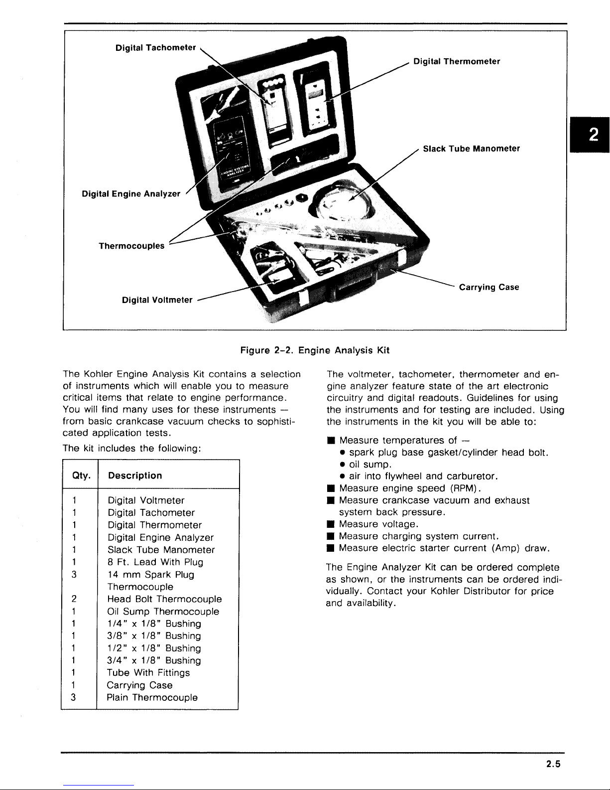
Figure
2-2.
The Kohler Engine Analysis Kit contains a selection
of
instruments
critical
items
You will find
from
basic
cated
application
The kit includes
Qty.
1
1
1 Digital
1
1
1
3
which will enable you
that relate
many
crankcase
uses
vacuum
to
for
engine
these
checks
tests.
the
following:
Description
Digital
Digital
Voltmeter
Tachometer
Thermometer
Digital Engine Analyzer
Slack Tube
Manometer
8 Ft. Lead With Plug
mm
14
Spark Plug
to
measure
performance.
instruments
to
sophisti-
-
Thermocouple
2 Head Bolt
1 Oil
1 1
1
1
1
1
Sump
/4"
318" x 1
1/2" X 1/8"
3/4" X 1/8"
Tube With Fittings
1 Carrying
3
Plain
Thermocouple
Thermocouple
x 1
/8"
Bushing
/8"
Bushing
Bushing
Bushing
Case
Thermocouple
Engine
Analysis
The
Kit
voltmeter,
gine analyzer
circuitry
the
and digital readouts. Guidelines
instruments
feature
the instruments
• Measure
temperatures
• spark plug base
• oil
sump.
• air into flywheel and
• Measure engine
• Measure
system
crankcase
back
• Measure voltage.
• Measure charging
• Measure
electric
The Engine Analyzer Kit can
as shown,
vidually.
or
the
Contact
and availability.
tachometer,
state
and
for
testing
in
the kit you will
gasket/cylinder
carburetor.
speed
vacuum
pressure.
system
starter
instruments
your
Kohler Distributor
Carrying
thermometer
of
the
art
are
be
of
-
(RPM) .
and exhaust
current.
current
be
ordered
can
be
Case
and
en-
electronic
for
using
included. Using
able to:
head bolt.
(Amp}
draw.
complete
ordered
for
indi-
price
2.5
Page 15

SECTION 3
PERIODIC MAINTENANCE
REQUIRED
These required maintenance procedures should be
MAINTENANCE
Required Maintenance
Check
Clean
Clean/Replace Fuel Filter
Clean Foam Precleaner . . . . . . . . . . . . . . . . . . . . . . . . . . . . . . . . . . . . . . . . . . . . . 25 Hours*
Change
Check Optional Reduction
Gear Unit . . . . . . . . . . . . . . . . . . . . . . . . . . . . . . . . . . . . . . . . . . . . . . . . . . . . . . . . . 50 Hours
Clean Cooling Fins and
External Surfaces . . . . . . . . . . . . . . . . . . . . . . . . . . . . . . . . . . . . . . . . . . . . . . . . . . 50 Hours*
Clean Paper Air
Cleaner Element . . . . . . . . . . . . . . . . . . . . . . . . . . . . . . . . . . . . . . . . . . . . . . . . . . 1 00 Hours*
Check Spark Plug . . . . . . . . . . . . . . . . . . . . . . . . . . . . . . . . . . . . . . . . . . . . . . . . . 1 00 Hours
Check
Clearance . . . . . . . . . . . . . . . . . . . . . . . . . . . . . . . . . . . . . . . . . . . . . . . . . . . . . . . 500 Hours
Clean Cylinder Head and
Combustion
Service Starter
Motor Drive . . . . . . . . . . . . . . . . . . . . . . . . . . . . . . . . . . . . . . . . . . . Annually
• Perform these maintenance procedures
Oil
Level . . . . . . . . . . . . . . . . . . . . . . . . . . . . . . . . . . . . . . . . . . . . . . . . . . . . . . . Daily
Grass Screen . . . . . . . . . . . . . . . . . . . . . . . . . . . . . . . . . . . . . . . . . . . . . . . . . . . . Daily*
..........................................
Oil
. . . . . . . . . . . . . . . . . . . . . . . . . . . . . . . . . . . . . . . . . . . . . . . . . . . . . . . . 25 Hours
Valve-
extremely dusty and dirty conditions.
To-
Tappet
Chamber*
..............................................
performed
more
frequently when engine is operated under
at the
frequency
stated
As Required
or
in
the table:
Frequency
500
Hours**
500 Hours
*
• 250 Hours when leaded gasoline is used.
~
WARNING: Accidental Starts!
Before
remove the spark
starting accidentally. Ground the lead to prevent
sparks that
CHECK
The
proper oil
phasized. Check oil
seNicing
OIL
importance
the engine
plug
to prevent the engine from
could
cause fires.
LEVEL
of checking and maintaining the
level in crankcase cannot be
BEFORE
or
equipment, always
EACH
USE
overem-
as follows:
1. Make sure the engine is stopped, level, and is
cool so the oil has had
sump.
2.
Clean the area around oil fill
fore removing
etc.,
out of the engine.
3. Remove
sert dipstick and push it
tube. Remove dipstick and
4.
On
engines with threaded
shoulder plug on
oil fill
to
keep dirt, grass clippings,
cap/dipstick;
top
time
to
drain into the
cap/dipstick
wipe oil off. Rein-
all the way down into
of
check
type
hole
the level.
plug dipstick,
to
observe level.
be-
3.1
Page 16

The oil level should
"F"
mark
on
the
dipstick. Refer
be
up to, but not over, the
to
Figure
3-1.
Precleaner
If
so
equipped,
every
tremely
25 operating hours
dusty,
wash and reoil
(more
dirty
conditions).
the
precleaner
often
under
ex-
Figure
5. Add the
Always
adding
CAUTION:
CHANGE
For a new engine,
hours
of
thereafter.
hours
those rebuilt with a
use straight
for
the first 5 hours
after
this initial
hours
thereafter.
warm
from
carry
away
proper
check
more
oil.
Never
operate
below
stick.
"L"
OIL
operation. Change oil
For an overhauled engine
30-weight
run-in
Drain oil while the engine is still
operation. The oil will flow freely and
more
impurities. Change oil as follows:
t
Operating
Range
__l_
L
3-1.
Oil Level Range.
type
of
oil if the level is low.
the level with dipstick
the engine with the oil level
mark
or
over
"F"
change
new
of
oil
after
the first 5
every
shortblock
Service Class
operation. Change the oil
period. Change oil
or
SF
before
mark
on
dip-
25 operating
or
miniblock,
or
SG
oil
every
25
1 . Remove
the
2.
Rinse
detergent
water (do not wring).
dry.
3. Saturate
Squeeze out excess oil.
4. Reinstall
precleaner
precleaner
precleaner
are eliminated. Squeeze out excess
precleaner
precleaner
from
paper
in warm
thoroughly until all
water
Allow
precleaner
in
clean, fresh engine oil.
over
paper
element.
with
element.
detergent.
traces
to
Paper Element
Every 100
tremely
element. Replace the element as necessary.
1.
Remove the precleaner (if so equipped), element
cover, and paper element.
2.
Replace a dirty, bent,
a genuine Kohler element. Handle new elements
faces are bent
NOTE:
Reinstall the paper element.
3.
4.
Install the precleaner (cleaned and oiled) over
the
hours
dusty
carefully; do not use of the sealing sur-
Do
not wash the paper element
pressed air as this will
paper
of operation
or
dirty conditions),
or
or
damaged.
element.
(more
damaged
damage
often under ex-
check
the paper
element with
or
element.
use
Wash
of
air
com-
1. Remove
engine
better
2.
Reinstall
ened securely.
Fill with new oil
3.
mark
on dipstick
the engine is
oil.
SERVICE
K-Series
paper
also
are
which surrounds the
ure
3-2.
the
oil drain plug and dipstick. Tilt the
slightly towards the drain hole to obtain
drainage.
the
drain plug. Make sure it is tight-
of
the
on
the
AIR
engines are
air
cleaner
equipped
proper
dipstick. Always
before
adding
level when filling and checking
CLEANER
equipped
element.
with an oiled
paper
Some
element.
type
check
more
with a
specifications
foam
3.2
to the
oil. Make sure
high-density
precleaner
Refer
"F"
the level
to
Fig-
5.
Install the air cleaner
en wing nut. Make sure element is sealed tightly against air cleaner base.
cover
and wing nut. Tight-
Inspect Air Cleaner Components
Whenever the air cleaner
icing the element
components:
Air
Cleaner Base - Make sure it
carburetor
Element
New Look
is not bent
nut
is
cleaner base and
50 in. lb. torque.
Breather
cleaner base and breather
and is not
Cover
~ngines
or
secured tightly to seal
Tube
or
and
only,
damaged.
element
- Make sure it
cover
precleaner,
bent
or
Element
make
Check
element
cover. Tighten nut to
cover.
is
removed,
check
is
damaged.
Cover
sure
that element cover
is
sealed tightly
the following
secured tightly to
Nut -On
element
between air
or
serv-
K181
cover
in
air
Page 17

"'--
PRECLEANER
(OPTION)
Figure
NOTE:
ponents could allow unfiltered air into the engine
causing
damaged
Damaged, worn,
premature
or
wear and failure. Replace all
worn components.
or
loose air cleaner
3-2.
Air Cleaner Components.
com-
CLEAN AIR INTAKE/COOLING AREAS
To ensure
screen, cooling fins, and other external surfaces
of engine are kept clean at
operating hours
dusty, dirty conditions), remove the blower housing and
fins and external surfaces as necessary. Make
sure the cooling shrouds are reinstalled. Refer to
the
"Disassembly"
cooling shroud removal and installation proce-
dures.
NOTE:
screen, dirty
ing shrouds removed
due to overheating.
proper
other
Operating the engine with a blocked grass
cooling, make sure the grass
all times. Every 50
(more
cooling shrouds. Clean the cooling
or
plugged cooling fins,
often under extremely
and "Reassembly" sections
and/or
will cause engine damage
cool-
CHECK SPARK PLUG
for
Ground Electrode
Figure
1 . Before removing spark plug, clean the area
around the base of plug to keep dirt and debris out of engine.
3-3.
Servicing Spark Plug.
Every 1 00 operating hours, remove the spark plug,
check
new plug as necessary. Refer
its condition, and reset gap
to
or
replace with
Figure
3-3.
2. Remove the plug and
place the plug if worn
able.
check
or
its condition.
if reuse is question-
Re-
3.3
Page 18

NOTE: Do not clean the spark plug
using abrasive grit.
spark plug and
wear and
3.
Check
gap by
enter
damage.
gap
using a wire feeler gauge. Adjust
carefully bending the ground electrode.
Some
grit could remain
the engine causing extensive
in
a machine
in
4. Reinstall
plug
spark
to
18/22 ft. lb.
plug into cylinder head. Torque
SERVICE OPTIONAL REDUCTION GEAR
UNIT
On
engines
check
hours. Refer
equipped
the oil level
to
Figure
with a reduction
in
unit
every
3-4.
gear
50 operating
unit,
Figure
3-5.
In-line
Fuel Filter.
SERVICE STARTER MOTOR DRIVE
Every 500 operating hours
occurs
of
1. Remove
2. Remove dust
first) , clean and lubricate the drive splines
the Bendix-drive
starter
propriate
spacer, spring, dust
pinion.
electric
from
"Disassembly"
cover,
or
annually (whichever
starter
crankcase. (Refer
stop nut, stop gear
cover
motor.
section.)
spacer, and drive
to
ap-
Drain Plug
(Oil Level
Figure
1 . Remove the plug on the lower part of
cover.
to the
2.
To add oil,
of
top
used
3.
Reinstall and tighten the plugs securely.
3-4.
Reduction Gear Unit.
With engine level, the oil should be up
bottom
the unit. Use the
in
of
the plug hole.
remove
the engine crankcase.
the vented fill plug at the
same
type of oil as
Check)
gear
unit
CHECK FUEL FILTER
Some
filter. Visually
to
engines are equipped with
inspect the filter periodically. Re-
place when dirty with a genuine Kohler filter. Refer
Figure
3-5.
an
in-line
fuel
3.
Clean the drive shaft splines with solvent. Dry
solvent thoroughly.
4.
Apply a small
drive
lubricant (Part No.
NOTE: Kohler
357 01) must be used on all Kohler
drives. The use
drive to stick
5.
Apply a small
stop nut threads. Assemble drive parts
verse
6. Reinstall
order
160 in. lb.
priate
"Reassembly"
amount
starter
of
other
or
bind.
amount
of
removal. Torque stop nut
starter
to
of
Kohler
52
drive lubricant (Part No.
lubricants can cause the
of
Loctite®
crankcase. (Refer
section.)
electric
357 01)
electric
No.
to
splines.
271
in
to
starter
52
starter
to
re-
to
appro-
CLEAN CYLINDER HEAD AND COMBUSTION CHAMBER
Every 500 operating hours (250 hours when leaded
gasoline is used) ,
combustion
remove
chamber.
cylinder head and clean
Refer to Figure
3-6.
3.4
Page 19

~1
Figure
1 . Remove the cylinder head baffle and cylinder
head.
2. Clean away
wooden
3. Reinstall the cylinder head using a new gasket.
Torque the cylinder head fasteners
quence
CHECK
Every 500 operating hours,
cover
flat feeler gauge. Refer to Figure
must
1 . Remove the air cleaner assembly, carburetor,
and
"Disassembly"
2.
Position the crankshaft so the piston
of
tappets).
3-6.
Cleaning Cylinder Head And
Combustion Chamber.
combustion
or
plastic scraper.
to
the values specified
VALVE-
and
check
be cold when checking this clearance.
breather
compression
TO-
valve-to-tappet
assembly. (Refer
section.)
stroke
deposits using a
TAPPET
remove
(cam
has no
in
se-
in
Figure
CLEARANCE
breather/valve
clearance with a
3-8.
The engine
to
appropriate
is
effect
3-7.
at top
on
K161, K181 •
15-20
0)2
7©8Q)14(Q)
Q)
©
3
Q5
K241,
K301, K321
25-30
ft. lbs.
9
©
ft. lbs.
~6
Figure
3-8.
Measuring ValveClearance.
To-
Tappet
Q)
3
g5
* Includes
Figure
3-7.
K341
25-30
ft. lbs.
g2
K141
Cylinder Head Fastener
Tightening Sequence.
Page 20

3. Measure
valve-to-tappet
clearance with a flat
feeler gauge.
On
Model
clearance is too small,
grind the valve
K91, K141, K161,
remove the valves and
stems
until the
K181
correct
-If
the
clearance is obtained. Make sure valve stems are
ground perfectly flat and smooth.
Model Intake Valve Exhaust Valve
K91
K161,K181
K241,
K321,
If
K301
K341
clearance is too large, replace the valves and
Figure
.005" I .009"
.006" I .008"
.008" I .01
3-9.
0"
Valve Clearances
.011
"/.015"
.017"/.019"
.017"/.019"
recheck clearance.
NOTE:
grinding the valves
the
for
On
Large clearances can also be reduced by
and/or
valve seats. Refer to
"Inspection And Repair/Reconditioning" section
valve specifications.
Models
K241, K301, K321,
K341
- Adjust the
clearance by turning the adjusting screw on tappets. Refer to Figure
3-9.
STORAGE
If the engine will be out
mately two months
storage procedure.
1 . Change the oil when engine is still warm from
operation. Refer to "Change
2. Change the oil
equipped. Refill with the
engine crankcase
fer
to "Service Optional Reduction Gear Unit. "
Run
engine
for
clean oil throughout engine.
3. Drain the
fuel tank and fuel system (or run
engine until fuel tank and fuel system are
empty).
4. Remove the spark plug. Add one tablespoon
of engine oil into the spark plug hole. Install
by do not connect plug lead. Crank the
plug,
engine two
or
5. Remove the spark plug. Cover the spark plug
with
hole
thumb
piston is at the top of its stroke (pressure
against thumb is greatest).
do not connect plug lead.
of
service
or
more,
use the following
Oil."
in
reduction
gear
same
for
season of operation. Re-
a few minutes
to
three revolutions.
and turn engine
Reinstall plug, but
for
approxi-
unit, if so
oil as used
distribute
over
until the
in
Figure
3-10.
Clearance Through
Adjusting
K341.
Valve-
Models
To-
Tappet
K241
6. Clean the exterior surfaces of engine. Spread
a light film of oil over any exposed metal surfaces of engine to prevent rust.
7. Store the engine
in
a clean, dry place.
3.6
Page 21

SECTION 4
TROUBLESHOOTING
TROUBLESHOOTING
When trouble occurs, be sure to
causes which, at first,
be considered. For example, a starting problem
could be caused
Some
listed below. Use this as a guide to locate trouble
causing factors.
Engine Cranks But
1 . Empty fuel tank.
2. Fuel shutoff valve closed.
3. Clogged fuel line.
4. Spark plug lead disconnected.
5. Keyswitch
6. Faulty spark
7. Faulty ignition.
8. Dirt
Engine
1 . Restricted
2. Dirt
3. Faulty choke
4. Loose wires
5. Carburetor improperly adjusted.
6. Faulty cylinder head gasket.
7. Faulty fuel pump.
Engine
1 . Hydrostatic transmission not
2. Loose wires
3. Dirt
4.
5. Faulty choke
6. Faulty spark plug.
7. Carburetor improperly adjusted.
8.
9. Low compression.
10. Faulty
Engine Will Not Crank
1 . Hydrostatic transmission is not
common
or
water
Starts
or
water
ground.
Starts Hard
drive is engaged.
or
water
Clogged
Incorrect
ACR
drive is engaged.
by
causes
or
kill switch
plug.
in
But
Does Not Keep Running
fuel tank vent.
in
or
or
or
in
or
restricted fuel lines.
or
valve-to-tappet
mechanism.
GUIDE
check
may
seem too obvious to
an
empty
of
Will Not Start
fuel system.
fuel system.
throttle controls/cables.
connections shorting ignition to
connections.
fuel system.
throttle controls/cables.
fuel tank.
engine troubles are
in
"off"
in
clearance.
the simple
position.
neutrai/PTO
in
neutrai/PTO
2. Battery is discharged.
3. Safety interlock switch is
or
4. Loose
5. Faulty keyswitch
6. Faulty electric starter/starter solenoid.
7. Retractable starter not engaging
8. Seized internal engine components.
Engine Runs
1 . Dirt
2. Spark plug lead loose.
3. Loose wires
ing ignition to ground.
4. Carburetor improperly adjusted.
5. Engine overheating.
6.
Incorrect
Engine Will Not Idle
1 . Idle speed adjusting screw improperly set.
2. Dirt
3. Idle fuel adjusting screw improperly set.
Fuel tank vent restricted.
4.
5. Faulty spark
6. Incorrect
7. Low compression.
Engine Overheats
1 . Grass screen, cooling fins
clogged.
2. Excessive engine
3. Low crankcase oil level.
4. High crankcase oil level.
5. Carburetor improperly adjusted.
Engine Knocks
1 . Low crankcase
2. Excessive engine load.
Engine Loses Power
1 . Low crankcase oil level.
2. High crankcase oil level.
3. Restricted air cleaner element.
4. Dirt
5. Excessive engine load.
6. Engine overheating.
7. Faulty spark
8. Carburetor improperly adjusted.
faulty wires
But
or
water
valve-to-tappet
or
water
valve-to-tappet
or
water
plug.
or
Misses
in
fuel system.
or
connections intermittently short-
in
fuel system.
plug.
load.
oil level.
in
fuel system.
"engaged"
or
connections.
ignition switch.
in
clearance.
clearance.
or
shrouding
.
drive cup.
II
4.1
Page 22

9. Low compression.
Engine Uses Excessive Amount of Oil
1. Incorrect oil viscosity
or
2. Clogged
system.
3. Worn
4. Worn cylinder bore.
5. Worn valve
improperly assembled breather
or
broken piston rings.
stems
or
and/or
type.
guides.
EXTERNAL ENGINE INSPECTION
0 Before cleaning
check
This inspection can give clues to what might
be found inside the engine (and the cause)
once
its external appearance and condition.
it is disassembled.
or
disassembling the engine,
CLEANING THE ENGINE
After inspecting the external condition of the engine, clean it thoroughly before disassembling.
Also clean individual components as the engine is
disassembled.
inspected and gauged
There are many commercially available cleaners
that quickly remove grease, oil and grime from
engine parts. When such a cleaner is used, follow
the
manufacturer's
sure all traces of the cleaner are removed before
the engine is reassembled and placed
tion. Even small amounts of these cleaners quickly
break down the lubricating properties of engine oil.
BASIC ENGINE
Only clean parts can be accurately
for
wear
or
damage.
instructions carefully. Make
in
opera-
TESTS
for
0 Check
crankcase, cooling fins, grass screen and
other external surfaces. Dirt or debris
areas are causes of overheating.
0 Check
aged components. Excessive oil leakage can
indicate a clogged
breather, worn
or
loose
0 Check the air cleaner cover, element cover
and air cleaner base
of improper fit
0 Check the air cleaner element. Look for holes,
tears, cracked
other damage that could allow dirt to enter the
engine. Also note if the element is clogged
restricted. These conditions could indicate that
the air cleaner has been underserviced.
0 Check the carburetor throat for dirt. Dirt
throat is further indication that the air cleaner
is not functioning properly.
0 Check the oil level. Note if the oil level
within the operating range
it is low
0 Check the condition
into a container - it should flow freely. Check
for
metal chips and other foreign particles.
NOTE:
away from the workbench.
time
Sludge is a natural
small accumu_lation
formation could indicate that the oil has not been
changed as
weight
settings
It
for
of
buildup of dirt and debris on the
in
these
for
obvious fuel and oil leaks and
or
improperly assembled
or
damaged seals and gaskets
or
improperly torqued fasteners.
for
damage
or
seal.
or
damaged sealing surfaces or
on
or
overfilled.
of
the oil. Drain the oil
is good practice to drain oil at a location
Be
sure to allow ample
complete
oil has been used,
or
weak ignition, to name a few.
drainage.
by-product
is
normal. Excessive sludge
recommended,
of combustion; a
an
over-rich
or
the dipstick,
incorrect type or
dam-
indications
in
is
or
carburetor
or
the
Fuel System Test
To
determine if fuel is getting
disconnect the fuel line at inlet to carburetor - if
fuel does not flow out of line,
to tank
cap, blocked filter screen, faulty fuel pump, etc.
fuel is getting as far as the carburetor, remove
the spark plug, crank engine and
inside combustion chamber.
here, check
for
clogged lines, wrong (unvented) filler
for
faulty carburetor.
to
the carburetor,
check
If
system back
check
no fuel is present
for
If
fuel
Ignition System Test
To determine if the ignition system is good, re-
move the spark plug and place plug with side
electrode against cylinder head then crank engine
at sufficient speed to produce a good spark.
sharp, snappy spark is noted, this eliminates the
ignition system components as the cause, al-
though the ignition timing could be off.
If
no spark
the ignition system further. If points are pitted,
don't
bad shape. Dirty points may be cleaned. A bad
condenser will cause premature failure of points.
if
Check the breaker push rod
ing
or
can be tested on commercial
manufacturer's instructions. Check ignition coil
coil tester for continuity.
or
a weak spark is produced,
attempt
sticking - replace as needed. Condenser
to service them - replace points
for
evidence of bind-
tester
per tester
If
check
a
in
on
Crankcase Vacuum
A partial vacuum should exist
when the engine is operating at normal temperatures. Pressure
by a clogged or improperly assembled breather)
can cause oil to be forced out at oil seals, gaskets
or
other available spots.
Crankcase vacuum is best measured with a slack
tube manometer. The
in
the crankcase (usually caused
manometer
in
the crankcase
included
in
the
4.2
Page 23

Kohler Engine Analysis Kit is
to
the
"Special
tion.
Tools"
section
Crankcase Vacuum Test
recommended.
for
more
informa-
Refer
side.
If
there
side is the
pressure
engine side)
following table.
same
(level
check
is no
vacuum
as in open side)
in
open side is higher than
for
(level
the conditions
in
engine
or
a positive
in
in
the
To
test
crankcase
1. Insert the
Leave the
to
the
atmosphere.
clamp
2.
Start the engine and run at high speed (3200
to 3600
3.
Open the
the
be 5
1.
Crankcase
2.
Seals
improperly
3.
Piston
inspecting
is closed.
RPM)
tube.
to
1 0 inches above the level
and/or
blowby
vacuum
stopper
other
vent
.
clamp
The level
and note the water level
Possible Cause
breather
gaskets leaking. Loose
torqued
or
leaky valves.
components.)
with the
hose into the oil fill hole.
of
the
manometer
Make sure the shutoff
in
the engine side should
NO
CRANKCASE VACUUM/PRESSURE
clogged
fasteners.
or
manometer:
in
inoperative.
or
(Confirm
open
in
the open
by
4. Close the shutoff
engine.
clamp
before
Compression Test
Because these engines are
matic
compression release
difficult
ing.
To
and related
crankcase
1.
Disassemble breather, clean parts
reassemble, and recheck pressure.
2.
Replace all
Make sure fasteners are
appropriate
necessary.
3.
Recondition
and valve guides.
to
check
obtain an
the condition
mechanisms,
vacuum
IN
CRANKCASE
worn
torque
piston, rings,
accurate
test
Solution
or
damaged
values and sequences when
equipped
mechanism
of
the
physical inspection and a
are
recommended.
tightened
cylinder
shutting
with an auto-
compression
combustion
thoroughly,
seals and gaskets.
securely. Use
bore, valves,
off
(ACR), it is
read-
chamber
the
II
4.
Restricted exhaust.
MEASURE
BETWEEN
DIFFERENCE
COLUMNS
Figure
4.
Replace restricted
4-1.
muffler/exhaust
system.
Figure
4-2.
"U"
Tube
Manometer
4.3
Page 24

SECTION 5
AIR CLEANER AND AIR INTAKE SYSTEM
K series engines are equipped with a
paper air
fications are also equipped with
precleaner that surrounds the paper element. Re-
fer
cleaner
to Figure
5-1.
element.
Engines of
high-density
an
oiled foam
some
speci-
AIR CLEANER DISASSEMBLY
1 . Remove the wing nut and air cleaner cover.
2.
Remove the precleaner (if so
per
element
3. Remove the base screws, air cleaner base,
gasket and hose.
and seal.
equipped),
pa-
AIR CLEANER SERVICE
Precleaner
If
so equipped, wash and
every 25 operating hours
tremely
1 . Wash the precleaner
2. Rinse the precleaner thoroughly
3. Saturate the precleaner with
4. Reinstall the precleaner
dusty
or
dirty conditions).
gent.
detergent
of
cess water (do not wring).
dry.
gine
oil. Squeeze out excess oil.
ment.
are eliminated. Squeeze out ex-
re-oil
the precleaner
(more
in
often under ex-
warm water and
Allow precleaner to
clean, fresh en-
over
the
deter-
until all traces
paper
ele-
II
Figure
5-1.
Air
Cleaner
"'------
Assembly
PRECLEANER
- Exploded View.
(OPTION)
5.1
Page 25

Paper Element
Inspect Air Cleaner Components
Every 1 00 operating hours
tremely
element. Replace
1 . Remove the precleaner (if so equipped), ele-
2.
NOTE:
compressed
3. Reinstall the
4.
5.
dusty
or
dirty conditions)
the
ment
cover
ment.
Replace a dirty, bent
new genuine Kohler
elements carefully;
bent
or
Do not wash the paper element or use
Install the precleaner (cleaned and oiled) over
the paper element.
Install the air cleaner
Tighten wing nut. Make sure element
tightly against air cleaner base.
nut, element cover and paper ele-
damaged.
air as this will damage the element.
paper
(more
element
or
element.
do
not use if surfaces are
element.
cover
often under ex-
check
as follows:
damaged
Handle new
and wing nut.
element with a
the
is
paper
sealed
Whenever the air cleaner
when servicing the paper element
check
1 .
2.
3. Breather
NOTE:
tain specifications, the element
the breather tube, making it impossible
crankcase vacuum.
the end of the breather tube that protrudes
through the air cleaner base at approximately a 45
degree angle.
the following components:
Air
Cleaner Base - Make sure it is secured
tightly to carburetor and is not bent
aged.
Element
K181
ment
that element
seal element between air cleaner base and
element cover. Tighten nut
torque. Refer to Figure
in
the air cleaner base and breather cover.
Cover and
New Look engines only, make sure ele-
cover
is not bent
cover
Tube
- Make sure it is sealed tightly
On
Model
K181
cover
is removed,
or
precleaner,
or
Element
nut is secured tightly
Cover
or
damaged. Check
to
Nut -On
50 in. lb.
5-2.
New Look engines of
cover
may
to
To
prevent this problem, cut
or
dam-
to
cer-
contact
maintain
Air
Cleaner
Cover
~
Figure
5.2
5-2.
K181
New Look,
Air
Cleaner
Assembly.
Air
Cleaner
Base
Breather
Hose
Page 26

NOTE:
ponents
causing
damaged
OPTIONAL OIL BATH
If
clean and
tion
to Figure
1 . Remove the
2.
NOTE: Do
ment. The filtering material could be damaged.
3. Lightly
4. Inspect base and
Damaged, worn
could
premature
the engine has an oil bath type air cleaner,
or
more
bowl and drain the oil
Thoroughly wash bowl and
vent.
low it
damaged.
allow unfiltered air into the engine
or
worn
service
frequently if conditions warrant. Refer
5-3.
cover,
Swish the
to
dry.
not
use
re-oil
the
or
loose air cleaner
wear and failure. Replace all
components.
AIR
CLEANER
it
after
every
lift the element out
element
compressed
element
cover
25
hours
of
from
the bowl.
cover
in
clean sol-
in
the solvent and al-
air to dry the ele-
with engine oil.
gaskets. Replace if
of
com-
opera-
the
5. Install base gasket and place filter on air horn.
6.
Add engine oil
mark.
7.
Install filter
Secure with wing nut finger tight only.
COOLING
Effective cooling
on an unobstructed flow
fins. Air is drawn into the cooling shroud
located on the flywheel. The blower housing, cool-
ing shroud, air screen covering the flywheel and
cooling fins on the cylinder and cylinder head
be kept clean and unobstructed at all
Never operate the engine with the blower housing
or
cooling shroud-removed. These devices direct
air flow
NOTE:
some
and
able unless other modifications are
engine.
AIR
over
Some
use metal. The two are
to
filter and fill
element,
cover
to
the
OIL
LEVEL
gasket and cover.
INTAKE SYSTEM
of
an air cooled engine depends
of
air
over
the cooling
by
fins
times.
the cooling fins.
engines use a plastic grass screen
not
interchange-
made
to
the
must
II
OIL LEVEL
Figure
5-3.
Optional Oil Bath Air Cleaner.
5.3
Page 27

SECTION 6
FUEL
SYSTEM AND GOVERNOR
FUEL SYSTEM - GASOLINE
The typical gasoline fuel
ponents include the fuel tank with vented cap,
shutoff valve with screen,
pump
(some
models),
necting fuel line.
system
in-line
carburetor
and related
fuel filter, fuel
and intercon-
Operation
The fuel
screen and shutoff valve,
lines by the fuel
Fuel enters the
into the
The
from
carburetor
fuel-air
the tank
pump
carburetor
is
moved
in-line
through the
filter and fuel
(if so equipped)
float bowl and
body
where it is mixed with air.
or
gravity.
is
moved
mixture is drawn into the combustion
com-
chamber
where it is
compressed,
then ignited by
the spark plug.
Troubleshooting
Use the following
reaching the combustion
~
WARNING: Explosive Fuel!
Gasoline may be present in the carburetor and fuel
system. Gasoline is extremely flammable and
explode
if
ignited. Keep sparks, open flames, and
other sources
connect and ground the spark
the possibility
procedure
to
check
that fuel is
chamber.
of
ignition away from the engine. Dis-
plug
lead to prevent
of
sparks from the ignition system.
it
can
II
Test
Check
1 .
A.
B.
C. Make sure the fuel
Check
2.
A.
B.
C.
D.
3.
Check
A.
B.
4.
Check
A.
B.
for
the
following:
Make sure
Make sure
Disconnect the spark plug lead.
Close the choke on
Crank
Remove the spark plug and check
Remove fuel line
Hold line below
valve and observe flow.
Remove fuel line
Crank engine several times and observe flow.
the
tank contains fuel.
the
fuel
for
fuel
In
the
the engine several
for
fuel
flow
from
from
bottom
operation
of
fuel
from
cap
vent
is
shutoff
valve
combustion
carburetor.
times.
tank
inlet fitting
of
tank. Open
pump
inlet fitting
open.
to
is
fuel
open.
chamber.
for
fuel
pump.
at
fuel pump.
shutoff
at
carburetor.
at
tip.
If
there
2.
bust ion
If
there
fuel tank.
3.
If fuel
does
(Test
4).
If fuel
does
vent,
shutoff
If
the fuel tank
the tank, modify
1/32"
to
If fuel
4.
does
line
Is
unobstructed,
placed.
If fuel
does
faulty. Refer
Is fuel
at
chamber.
Is
no
fuel
(Test
flow
not
valve
cap
1 I 1 6"
off
not
flow
to
Conclusi~n
tip
of
spark plug, fuel
at
tip
of
3).
from
flow
screen,
the
the
flow
from
the
spark plug, check
line, check
from
line, check
and fuel lines.
vent does not allow air
vent
for
proper
bottom.
from
fuel
fuel line, the
"Carburetor"
Refer
line, check
pump
Is
is
reaching
for
for
faulty fuel pump.
for
clogged fuel tank
to
operation by cutting
to
faulty and
carburetor
portion
escape
Figure 6-1 .
for
clogged fuel line. If
must
probably
of
this section.
fuel
be
the
from
re-
com-
the
from
Is
6.1
Page 28

Cut Off
1/32"-1/16"
Operation
The mechanical fuel
that rides on the engine camshaft. The
transmits a pumping action to the flexible diaphragm inside the
tion draws fuel in through
the downward stroke of the diaphragm.
upward stroke, the
outlet
check
valve. Refer
pump
is operated by a lever
lever
pump
body. The pumping
the
inlet
check
fuel is forced out through the
to
Figure
valve on
On
6-2.
ac-
the
Figure
6-1.
("New
Fuel
Look"
Tank
Only)
Cap.
FUEL TANK
Engine-mounted
are
constructed
vented cap. The venting properties of the cap
should be
cause pressure buildup
result
is
loosened.
the tank, stopping the engine.
Fuel
Some
valve with a wire mesh screen.
a shutoff valve, a straight outlet fitting is used.
The wire
the tank
valve permits work on the fuel system without the
need
checked
in
fuel spraying
Shutoff
engines are equipped with a fuel shutoff
mesh
from
for
draining the tank.
fuel tanks on K series engines
of
steel. They are fitted with a
regularly. A clogged vent can
in
the tank, which could
from
the filler when the cap
It
can also cause a partial vacuum
Valve
On
engines without
prevents relatively large particles
reaching the carburetor. The shutoff
FUEL FILTER
Some engines covered by this manual
equipped with a
When
the
interior of the filter appears
it should
be
see-through
replaced.
in
line fuel filter.
may
to
be dirty,
be
FUEL PUMP
All K series engines except the
for
sions
pump.
gines, a
pad on the crankcase.
Older fuel
els have a
better
mizing the
mounting a mechanically operated fuel
If
no fuel
cover
pumps
insulates the fuel
pump
is placed over the
body
made
chance
is mounted on these en-
have a metal body. Later
of plastic. The plastic body
of
vapor
from
K91
have provi-
pump
mounting
mod-
the hot engine, mini-
lock.
in
in
Figure
6-2.
Mechanical
Fuel
Pump.
Removal
1 . Disconnect the fuel lines
outlet fittings
2. Remove the fillister head
washers, fuel
3.
If
required, remove the fittings
body.
of
the
pump
from
the inlet and
pump.
sems
and gasket.
screws, flat
from
the pump
Repair
Plastic bodied fuel
must be replaced when faulty. Replacement
pumps are available
pump, mounting gasket and
pumps
are not serviceable and
in
kits which include the
plain washers.
Installation
1 . Fittings - Apply a small amount
Aviation Perm A Gasket (or equivalent gasoline
resistant thread sealant)
in
to
pump
the
Figure
same
tings into
fittings
rection is reached.
Install new gasket, fuel
2.
lock washers and
Refer
six
fillister head
6-3.
to
full
turns;
direction until desired di-
pump,
of
Permatex®
fittings. Turn fit-
continue turning
flat washers,
sems
screws.
6.2
Page 29

Plain Washer (2)
~
-----
~~
,:IJ..
Fillister Head Sems
L
Screws
Figure
NOTE:
tioned above the
pump
sult if the lever
Make sure that the flat washers are installed next
to the mounting flange
the lock washers.
If
bodied
is discarded and the new thin gasket
3. Torque screws to
4. Connect fuel lines
Make sure that the fuel
and severe
a metal bodied
pump,
make
(2)
6-3.
Installing Fuel Pump.
camshaft.
damage
is
positioned below the camshaft.
to
pump
was replaced by a plastic
sure that the old thick gasket
37 - 45
to
inlet and outlet fittings.
\Fuel
pump
Damage to the fuel
to the engine could re-
prevent
in.llb.
CARBURETOR -GASOLINE
Pump
Mounting
lever
damage
is
used.
Flange
is
posi-
from
tor. This gives a
the adjusting needles out (counterclockwise) increases the supply
gives a
dles midway between the lean and rich positions
will usually give the best results. Adjust the carburetor as
1 . With the engine stopped, turn the low idle fuel
NOTE:
adjusting needles are tapered
Damage to the needles and the seats
body will result if the needles are
2.
3. Start the engine and run at half throttle
4. High Idle Fuel Needle Setting: This adjustment
Place the throttle into the
ble, place the engine under load.
Turn the high idle fuel adjusting needle out (counterclockwise)
engine speed
of the needle.
richer
follows:
adjusting needle
lightly.
The tip
Preliminary Settings: Turn the adjusting needles
out (counterclockwise)
according to the table shown
to ten minutes to warm up. The engine must
be warm before making final settings (Steps 4,
5,
6,
and
is
required only
jet
carburetors.
jet
main
leaner
fuel-to-air
of
the low idle fuel and high idle fuel
7).
type,
from
decreases
fuel-to-air
of
fuel
to
mixture. Setting the nee-
in
(clockwise) until it
from
for
adjustable high idle (main)
If
the
carburetor
go
to
step 5.
"fast"
the preliminary setting until the
(rich}. Note the position
mixture. Turning
the carburetor. This
to
critical dimensions.
in
forced.
lightly
bottomed
in
Figure
is
a fixed
position.
bottoms
carburetor
6-4.
for
five
If
possi-
II
•
£ WARNING: Explosive Fuel!
Gasoline may
system. Gasoline is extremely flammable
explode
other sources
connect
the possibility
Adjustment
The
carburetor
fuel/air mixture
conditions. Carburetors are set at the
normally
exhibits conditions like those found
that
follows, it
carburetor.
In
general, turning the adjusting needles in (clock-
decreases
wise)
be
present in the carburetor
if
ignited. Keep sparks, open flames, and
of
ignition away from the engine. Dis-
and
ground the spark
of
sparks from the ignition system.
is designed to deliver the
to
the engine under all operating
do
not need adjustment.
may
be necessary to adjust the
the supply of fuel to the carbure-
plug
and
fuel
and
it
can
lead to prevent
correct
factory
If
the engine
in
the table
and
Now turn the adjusting needle
may
engine speed
as the needle
of the needle.
Set the adjusting needle midway between the rich
and lean settings. See Figure
5. Low Idle Speed Setting: Place the throttle control into the
low idle speed to
by turning the low idle speed adjusting screw
in
or out. Check the speed using a
ter.
NOTE:
application. Refer to the
instructions
The
gines
setting the low idle fuel needle, the low idle speed
must not exceed
The actual low idle speed
for
recommended
is
1200 rpm. To ensure best results when
increase, then it will
is
turned
"idle"
specific low idle speed settings.
1500
in
or
1200
low idle speed
rpm.
in
(clockwise). The
decrease
(lean). Note the position
6-5.
"slow"
equipment
position. Set the
rpm*
( +
or
depends
manufacturer's
for
- 75 rpm)
tachome-
on the
Basic En-
6.3
Page 30

PRELIMINARY SETTINGS - K-SERIES MODELS
KOHLER
Low
K91
K141
K161*
K181*
K241
K301
K321
K341
6. Low Idle Fuel Needle Setting: Place the throttle
into the
Turn the
terclockwise)
engine speed decreases (rich). Note the position
of the
Now turn the adjusting needle in (clockwise). The
engine speed
as the
of the
Set
the adjusting needle
lean settings. See Figure
and
"idle"
low idle fuel adjusting needle
from
needle.
may
needle is turned in (lean). Note the position
needle.
1-1/2
1-1/2
1-1/2
1-1/4turns
2-1/2
2-1/2
2-1/2
2-1/2
• Includes
Figure
or
6-4.
"slow"
the preliminary setting until the
increase, then it will decrease
midway
ADJUST
Idle High Idle Low Idle
turns
turns 3 turns
turns
turns 2 turns
turns 2 turns
turns
turns
"New
Preliminary
position.
between the rich
6-5.
Look"
ABLE
2 turns
3 turns
2 turns
3-1/4
3-1/2
Models
Low
out
(coun-
JET
turns
turns
Idle And High Idle Fuel Needle
WALBRO
2. Remove the
3. Remove the
4. Further disassembly
FIXED
NOT
NOT
NOT
2-1/2
1-1/4
1-1/4turns
1-1/2
1 turn
baffle
ket. Remove the
ing
speed adjusting
choke shafts is
parts are
and Choke Shaft Replacement" later
section.
JET
APPL.
APPL.
APPL.
turns
turns
turns
gasket and bowl gasket.
needles and springs. Remove the idle
to
NOTE: Refer
tion TP2377B Carburetor
Reference Manual for
additional information.
Settings.
float pin, float, fuel inlet needle,
fuel inlet seat and inlet seat gas-
idle fuel and main fuel adjust-
screw
recommended
be replaced. Refer
and spring.
to
to
publica-
remove the throttle and
only if these
to
"Throttle
in
this
7. Recheck the low idle speed using a
ter. Readjust the speed as necessary.
Adjust
Midpoint
Figure
6-5.
To
Optimum
Low
Idle Fuel
tachome-
Lean
Setting.
Disassembly
(Refer
1 . Remove the bowl retaining screw, retaining
to
screw
Figure
gasket and fuel bowl.
6-7)
Idle
Speed
Screw
Figure
6-6.
Kohler-Built
Carburetor.
Main Fuel
~Needle
Adjustable
Jet
6.4
Page 31

Cleaning
WARNING:
All parts should be carefully cleaned using a carburetor cleaner (such as
gum
deposits are
eas:
Carburetor
where throttle plate, choke plate and shafts are
seated.
Float
and
Fuel bowl.
Idle
fuel
ports
fuel
seat.
NOTE:
of fine wire
to enlarge the ports
within the ports.
Flammable
Carburetor cleaners and solvents are
extremely flammable. Keep sparks,
flames
away from the area. Follow the
cleaner manufacturer's warnings and
instructions on its proper and
use.
Never use gasoline as a clean-
ing agent.
body
and
float
hinge.
and
"off-idle"
in
main
fuel
These areas can be cleaned using a piece
in
addition
Solvents!
and
other sources
acetone).
removed
adjusting
or
from
the following ar-
bore;
especially the areas
ports
in
carburetor
needle
to
cleaners.
break the cleaning wire
of
ignition
Be
sure all
and
main
Be
careful not
safe
bore,
Main Fuel
VNeedle
Idle
Speed
Screw
/Spring
iJ
\
J~/
~pring
/
@
Carburetor
Body
,-~~~~
Idle
Fuel
Needle /
~~:!
~~~
Gasket e
Fuel/~
Inlet
Seat
j
Fuellnlet
Needle \
Float~
Fuel
____
Bowl
~-==-~--------
~
~~Gasket
~
~~Hinge
~
r-~---~~
~
1
~~:~
..
Baffle
II
Float
Float
p;,
Blow out
NOTE: Do not
solvent when fiber
The cleaner
all passages with
submerge
may
or
damage
compressed
carburetor
rubber seals are installed.
these seals.
air.
in
cleaner or
Inspection
1 . Carefully inspect all
those that are worn
2. Inspect the
and
other
Inspect the float
3.
float hinge
float tabs.
Inspect the inlet needle and seat
4.
grooves.
5.
Inspect the tips
justing needles
Inspect the throttle and choke shafts and plate
assemblies
carburetor
wear
for
for
components
or
damaged.
body
or
damage.
for
dents
wear and missing
of
the main and idle fuel ad-
for
wear
or
wear
or
excessive play.
and replace
for
cracks, holes
or
holes. Check the
or
for
grooves.
damaged
wear
or
Bowl
Retaining-~
Screw
Figure
6-7.
Kohler-Built
Carburetor
~--Bowl
Screw
Adjustable
- Exploded View.
Retaining
Gasket
Jet
Choke Plate Modification
The choke action has been changed on production
carburetors to
On
ing.
K321
plate have been enlarged
K241
the other is
are
mensions.
NOTE:
sary precautions
the engine.
production carburetors now used on the
and
and K301, one relief hole is now
smaller than this, enlarge
When redrilling the holes, take the neces-
reduce
K341
, both relief holes
3/16" . If
the chances of
to
11
/32"
you find that the relief holes
them
to
prevent chips
over
in
the choke
while on the
11/32"
to these di-
from
chok-
and
entering
Repair
Always use new gaskets when servicing and reinstalling carburetors. Several repair kits, which in-
other
clude the gaskets and
components,
are
6.5
Page 32

available. Always refer
engine being serviced to ensure that the
carburetor
ordered.
repair kits and replacement parts are
to
the Parts Manual
for
the
correct
Throttle
And
Choke Shaft
Replacement
To Replace Throttle And Choke Shafts
Two kits are available that allow replacement of
the carburetor
carburetors. Refer
throttle and choke shafts of Kohler
to
Figure
6-8.
Choke
Choke Plate (Reused) \
Detent
Choke
Ball-Spring__.'"'
Shaft
?~(Q
#3-48x7/32"
Brass Screws £
I
#2-56x7/32"
#3-48x7
Brass
/32"
Screw
l:J/,Y
.,.~
or
'choke
~
"'Choke
Choke
Bushing
Shall
Lever
(Reused)
#2-56x7/32"
B<ass
Throttle
For
KT17-KT19,
Shaft
~
, _ (Reused)
Shaft
Models
Bushing
K241-K341 &
1"
\ Brass Screws _ Lever
or
#3-48x7/32"
Sc,.w
~
-4
Styles y
~
ca,b.
~
~
#3-48x7/32"
~,
~
'S~~\J
"""'-
,
'"\]
/~--"
Throttle
2 Styles For
K91-K181,
/
+ -
'Th,ottle
Throttle
Shaft/Lever
Models
1/2"
Carb.
Throttle
_j
Shaft Bushing
Plate (Reused)
\Throttle
Installation
Assembly-
1
Shaft
Tool
Bushing
Figure
6-8.
A WARNING: Prevent Eye Injury!
Suitable eye protection (safety glasses, goggles,
face hood) should be worn for any procedure involving the use
chisels, drills,
Disassemble Carburetor
Refer
section.
6.6
of
compressed
or
grinding tools.
to
"Disassembly"
air,
punches, hammers,
at the beginning
Throttle
of
this
And
Choke Shaft Replacement Kits.
Remove Choke Plate and Choke Shaft;
or
Transfer Choke Lever
1. To ensure
plate and carburetor body with a marking pen.
Also take note
and choke lever position.
2. Carefully and slowly
ing choke plate to choke shaft. Remove and
save the choke plate as it will be reused.
correct
reassembly,
of
choke plate position
remove
the screws secur-
mark
choke
in
bore
Page 33

3. File
4. Note the position
5.
6.
Models
#2-56 x 7/32"
Models K241 - K341
#3-48 x 7/32"
off
any burrs which
choke
the
moved.
choke
detent
spect
shaft.
Carefully grind
of
the shaft. Remove and save the choke
lever; discard the old
Attach the
from
correctly
choke
K9
shaft when the screws were re-
Place
carburetor
side down. Remove
ball and spring will fall out.
to
the
cut
out portion
or
choke
the kit. Make sure the lever
as noted
shaft as follows:
1 - K181
,-
Apply Loctite to threads
brass screw. Secure lever
,-
brass screw. Secure lever
may
have been left on
on workbench with
choke
of
the
choke
file away the riveted portion
choke
lever to the new choke shaft
in
step 4. Secure lever to
Apply Loctite
shaft; the
lever with re-
of
the
shaft.
is
to
threads of 1
choke
installed
to
to
of
1
shaft.
shaft.
Remove Throttle Plate and Throttle Shaft;
Transfer
1 . To ensure
plate
Also take
the
Throttle Lever
correct
and
carburetor
note
bore
and the throttle lever position.
reassembly,
body
with a marking pen.
of
the throttle plate position
mark
throttle
in
c.
Compare
the kit. Select the appropriate new shaft and
discard the
d. Attach
sure
step a.
Apply Loctite
e.
brass
is
2-49/64"
Drill
Choke Shaft Bores Using A
the old shaft with the new shafts
old shaft.
throttle lever to throttle shaft. Make
lever is installed
to
screw
(use
long.
correctly
threads
of
1
#3-48 x 7/32"
Secure
lever
as noted
#2-56 x 7/32"
screw
to
shaft.
Press
1. Mount the
Keep the vise jaws
2.
Install a drill bit
press chuck. Lower the bit (not rotating)
through both
vise. This ensures
carburetor
Models
ameter
Models K241 - K341
ameter
Refer to Figure
K91
drill bit.
drill bit.
carburetor
choke
body
- K181
6-9.
body
in
a drill press vise.
slightly loose.
of
the following size
shaft bores; then tighten
accurate
with the drill press
(1
12"
(1"
Garb.);
alignment of the
Garb.);
Use a 7132" di-
Use a 1
chuck.
Drill
in
the drill
/4"
in
in
if shaft
di-
II
Carefully and slowly
2.
ing the throttle plate
and save the
File
3.
NOTE: Failure
shaft
body
4. Remove throttle shaft
5. Remove and transfer the
Models
Carefully grind
the
be used
Discard the
Models K241 - K341
a. Note the position
b.
off
throttle shaft when screws were
the
may
cause
when shaft is
Remove and discard the
from
the throttle shaft.
lows:
K91
throttle shaft. Save the throttle shaft as it will
to
spect
to
shaft.
Carefully grind
of
the shaft. Remove the throttle lever.
throttle plate
any burrs that
to
remove
permanent
- K181 (112" Garb.),-
or
install the new throttle shaft bushing.
throttle lever.
the
cutout
remove
to
may
burrs
removed.
from
file away the riveted portion of
(1"
Garb.),-
of
the throttle lever with re-
portion of the throttle
or
file away the riveted portion
the screws
throttle shaft. Remove
for
reuse.
have been left on
from
the throttle
damage
foam
throttle lever as fol-
to
carburetor
rubber dust seal
secur-
removed.
carburetor
body.
Figure
3.
4. Ream the
5.
6-9.
Aligning/Drilling Carburetor Body.
Install a 19/64" drill bit
press
to
a low speed suitable
Drill slowly
5/16".
reamer.
Blow out all metal chips using
Thoroughly clean the
retor
to
ensure a
choke
For best results use a piloted 5/16"
cleaner.
shaft bores
in
the
chuck.
for
good
finish.
to
compressed
carburetor
Set drill
aluminum.
a final size of
air.
body
in
carbu-
6.7
Page 34

Install Choke Shaft Bushings
1 . Install screws
the choke shaft bores until the screws bottom
lightly. Refer to Figure
2. Coat the outside surface of the kit-supplied
choke shaft bushings with Loctite from the kit.
Carefully press the bushings into the carburetor
body
pressing when bushings bottom against
screws.
Models
bushing is pressed below the surface of the large
choke shaft boss until the bushing
screw.
K91 -K181
in
using a
the tapped holes that enter
6-10.
smooth-jawed
vise. Stop
(112" Carb.); Make sure the
bottoms
against
2. Install a throttle shaft (without throttle lever)
carburetor body
Models
throttle shaft removed previously.
Models
remaining new throttle shafts from the kit.
3. Coat the outside surface of the throttle shaft
K91 -K181
K141 -K341
bushing with Loctite from the kit. Slip the
bushing over the shaft. Using a vise and the
installation tool
into the counterbore until it
buretor body. Refer to Figure 6-11 .
to
use as a pilot:
(112" Carb.); Use the old
(1"
Carb.); Use one of the
from
the kit, press the bushing
bottoms
in
the car-
in
Allow Loctite to
3.
then
remove
Figure
4. Install new choke shaft
NOTE:
cause before proceeding. Use choke shaft to align
bushings if necessary.
5. Remove choke shaft and
6. Wipe away any excess Loctite from bushings
6-10.
shaft and
If binding occurs, locate and
for
an additional 30 minutes before proceed-
ing.
and choke shaft.
"set"
for
5 to 1 0 minutes,
screws.
Installing Choke Shaft Bushings.
in
bushings. Rotate
check
that it does not bind.
correct
allow Loctite to
the
"set"
Install Throttle Shaft Bushing
1 . Make sure the dust seal counterbore
carburetor body is thoroughly clean and free of
chips and burrs.
in
the
Figure
4. Allow the Loctite to
5.
NOTE:
before proceeding. Use throttle shaft to align bushing
if necessary.
6. Remove the shaft and allow the Loctite to
7.
Install Detent Spring and
6-11.
Installing Throttle Shaft Bushing.
"set"
for
5 to 1 0 minutes,
then remove the throttle shaft.
Install the new throttle shaft and lever
retor body. Rotate the shaft and
does not bind.
If
binding occurs, locate the cause and correct
"set"
for
an
additional 30 minutes before pro-
ceeding.
Wipe away all excess Loctite from bushing and
throttle shaft.
·
Ball,
in
check
Choke
carbu-
that it
Shaft and Choke Plate
1 . Install new detent spring and ball
body
in
the side opposite the choke lever.
2. Compress detent ball and spring and insert
choke shaft through bushings. Make sure the
choke
buretor body. Refer to Figure
lever is on the
correct
in
carburetor
side of the car-
6-12.
6.8
Page 35

3. Attach choke plate
marks are
erly
in
#3-48 x 7/32"
that they are slightly loose.
aligned and plate is positioned prop-
the bore. Apply Loctite to threads of 2
brass screws. Install screws so
to
choke shaft. Make sure
Reassembly
1 . Install the fuel inlet seat gasket and fuel inlet
seat into carburetor body. Torque seat to
35/45
in.
lb.
4. Operate the choke lever. Check that there is
no binding between choke plate and carburetor
bore. Loosen screws and adjust plate as necessary; then tighten screws.
Figure
6-12.
Installing Choke Shaft.
2. Install the fuel inlet needle into inlet seat. Install float
and float hinge towers on carburetor body.
3. Set
tab rests on the fuel inlet needle. There should
be 11/64"
machined surface
float. Bend the float tab with a small screw-
driver to adjust. Refer
Bend
To
and slide float pin through float hinge
float
level: Invert carburetor so the float
(+-
Tab
Adjust
Figure
1/32")
Inverted
6-13.
clearance between the
of
body
and the free end of
to
Figure
Carburetor
Setting
6-13.
Float Level.
Install Throttle Shaft and Throttle Plate
1 . Install throttle shaft
of
portion
2. Attach
sure
properly
of
2
screws
3. Apply finger pressure to throttle shaft to keep
it firmly seated against pivot
body. Rotate the
plate fully closes the bore around its perimeter; then tighten screws.
4. Operate
throttle plate does not bind
Loosen screws and adjust plate if necessary;
then tighten screws securely.
the shaft facing out.
throttle plate
marks
are aligned and plate is positioned
in
the bore. Apply Loctite to threads
#3-48 x 7/32"
so
that they are slightly loose.
the
throttle lever and
in
carburetor with cutout
to
throttle shaft. Make
brass screws. Install
in
carburetor
throttle shaft until the throttle
check
in
the bore.
that the
Reassemble Carburetor
Refer
to
the following "Reassembly" portion of this
section.
4. Set
float
drop:
Turn the carburetor over to its
normal operating position and allow float
drop to its lowest level. The float
be limited
surface of body and the
end
screwdriver
to
1-1/32"
of
float. Bend the float tab with a small
to
adjust. Refer
between the machined
bottom
to
Figure
-t
1-1/32"
t
Figure
6-14.
Setting
Float Drop.
drop
of
the free
Bend
To
to
should
6-14.
Tab
Adjust
6.9
Page 36

5.
Check
Invert the carburetor so the float tab rests
the fuel inlet needle. Insert a .
gauge between float and float hinge towers.
the feeler gauge cannot be inserted,
is interference between the float and towers,
file the towers to obtain the proper clearance.
Refer to Figure
float-to-float
6-15.
hinge
tower
01
clearance:
0"
feeler
or
there
on
6. Install the bowl gasket and baffle gasket. Posi-
tion baffle gasket so the inner edge is against
the float hinge towers.
7. Install the fuel bowl so it is centered on the
baffle gasket. Make sure the baffle gasket and
bowl are positioned properly to ensure a good
seal.
8. Install the bowl retaining screw gasket and
bowl retaining screw Torque screw to 50/60 in.
lb.
WALBRO FIXED/ADJUSTABLE
CARBURETOR
If
This section covers the idle adjustment, disassembly, cleaning, inspection, repair, and reassembly
of the
main
Walbro-built,
jet
carburetors.
Idle Speed
Adjusting
Screw
side
draft,
fixed/adjustable
Idle Fuel
Float
If
File
Inverted
9.
Carburetor
Figure
Install the idle speed adjusting screw and
spring.
justing needles and springs. Turn the adjusting
needles clockwise until they bottom
6-15.
Install the idle fuel and main fuel ad-
Checking
0.010" Feeler Gauge
(Both
·r·l
Float
Hinge
(On
Carburetor
Float Clearance.
Towers
lightly.
Body)
Figure
~
Before servicing the carburetor, engine,
ment, always remove the spark
the engine from staning accidentally. Ground the
leads to prevent sparks that
~
Gasoline may
system. Gasoline is extremely flammable
vapors can explode
flame,
area to prevent the possibility
6-16.
WARNING: Accidental Starts!
WARNING: Explosive Fuel!
and
other sources
Fixed Main
be
present in the carburetor and fuel
if
ignited. Keep sparks, open
of
Jet
plug
could
cause fires.
ignition away from the
of
fires
Carburetor.
or
equip-
leads to prevent
and
its
or
explosions.
NOTE:
to critical dimensions. Damage to needles and
seats will result if needles are forced.
10. Reinstall the carburetor to the engine using a
11
The ends
new gasket.
. Adjust the carburetor as outlined under the
"Adjustment"
6.10
of
adjusting needles are tapered
portion of this section.
~
WARNING: Prevent Eye Injury!
Suitable eye protection (safety glasses, goggles,
face shield) should be worn for any procedure involving the use
mers, chisels, drills,
of
compressed
or
grinding tools.
air,
punches, ham-
or
Page 37

Choke
Ball
And
I
I
Detent
Spring
Date
Code*
Idle
Speed
Screw
And
Idle
Fuel
Needle
Welch
Choke
Shaft
Adjusting
Spring
'NOTE:
lever) Side
the
bottom
Adjusting
And
Spring
Plugs
Lever/
Assembly
These
of
(fuel
will
be
mount1ng
bowl)
on
flange
s1de
e1ther
of
the
top
(throttle
as
shown,
mounting
or
flange
---c_ Fuel
on
Throttle
Shaft
Bowl
Screw
Lever/
Assembly
Retaining
And
Gasket
Mounting
Idle
Bleed
Flange
Air
"Off-Idle"
Port
Throttle
Plate
Fuel
Bowl
Gasket
Fixed
Fuel
Main
Jet
I
I
I
I
I
I
Drop
Tab
I
Float
Limiting
(Non-Adjustable)
II
Nozzle
Air
Bleed
Figure
6-17.
Major
Components
Air
Cleaner
Mounting
And
Bowl
Surface
Service
Vent
Idle
Inlet
Locations -Typical
Fuel
Fixed
Jet
Carburetor.
Fuel
Inlet
Needle
6.11
Page 38

TROUBLESHOOTING
If engine troubles are experienced that appear to
be fuel system related,
before adjusting
•
Make sure the fuel tank is filled with clean,
fresh gasoline.
• Make sure the fuel tank
blocked and that it is operating properly.
• Make sure fuel is reaching the carburetor. This
includes checking the fuel
tank filter screen, in-line fuel filter, fuel lines,
and fuel
nents as necessary.
or
pump
check
disassembling the carburetor.
for
restrictions
the following areas
cap
vent is not
shut-off
or
faulty
valve, fuel
compo-
• Make sure the carburetor
to the engine using gaskets
• Make sure the air cleaner element is clean
and all air cleaner components are fastened
securely.
• Make sure the ignition system, governor system,
exhaust system, and throttle and choke
controls are operating properly.
If, after checking the items listed above, starting
problems
in
the following table exist, it
adjust
or
other conditions similar to those listed
or
service the carburetor.
is.
securely fastened
in
good condition.
may
be necessary to
Condition
1. Engine starts hard,
runs roughly
idle
speed.
2. Engine runs rich.
(Indicated
sooty exhaust smoke,
misfiring, loss
speed and power,
governor hunting,
excessive throttle
opening.)
Engine runs lean.
3.
(Indicated
loss
of
power, governor hunting,
or
throttle opening.)
or
stalls at
by
black,
of
by
misfiring,
speed and
excessive
or
or
Possible Cause/Probable Remedy
1. Idle fuel mixture
idle speed screw, then adjust idle fuel needle.
2a. Choke
linkage
b. Idle fuel mixture is improperly adjusted. Adjust idle fuel needle.
c. Float level set too high. With fuel bowl removed and carburetor in-
verted, set exposed surface
surface of carburetor body.
d. Dirt under fuel inlet needle. Remove needle. Clean needle and seat
and blow with compressed air.
Bowl vent
e.
ing
out all passages with compressed air.
Fuel bowl gasket leaks. Remove fuel bowl and replace gasket.
f.
g. Leaky, cracked,
leaks.
3a. Idle fuel mixture is improperly adjusted. Adjust idle fuel needle.
b. Float level set too low. With fuel bowl removed and carburetor in-
verted, set exposed surface
surface of carburetor body.
Idle holes plugged; dirt
c.
idle fuel adjusting needle, main fuel jet, and welch plugs. Clean all
passages and blow out with compressed air.
partially closed during operation. Check the choke lever and
to
or
needle, and welch plugs. Clean vent, ports, and air bleeds. Blow
or
idle speed are improperly adjusted. Adjust the
ensure choke is opening after
of
float parallel with the bowl gasket
air bleeds plugged. Remove fuel bowl, idle fuel adjust-
or
damaged float. Submerge float
of
float parallel with the bowl gasket
in
fuel delivery channels. Remove fuel bowl,
warm-up.
to
check
for
Fuel leaks
4.
carburetor.
6.12
from
4a. Float level set too high. See Remedy 2c.
b. Dirt under fuel inlet needle. See Remedy 2d.
c.
d. Float is cracked
e. Bowl retaining screw gasket damaged. Replace gasket.
f. Bowl retaining screw is not tightened. Torque screw
Bowl vent plugged. Remove fuel bowl and clean bowl vent. Blow out
with compressed air.
or
damaged. Replace float.
to
specifications.
Page 39

In
general, turning the adjusting needles
wise) decreases the supply of fuel to the carburetor. This gives a
the
adjustfng needles
creases the supply of fuel
gives a richer
needles
tions will usually give the best results.
midway
leaner
fuel-to-air
between the lean and rich posi-
fuel-to-air
out
(counterclockwise) in-
to
the carburetor. This
mixture. Setting the
In
(clock-
mixture. Turning
Figure
Adjust
To
6-18.
Midpoint
Fixed Main
Idle
Adjusting
Jet
Carburetor.
Lean
Fuel
Needle
Adjust the carburetor as
1. With the engine stopped, turn the low idle fuel
adjusting needle
lightly.
2.
Preliminary
dles out (counterclockwise)
tomed
6-20.
3. Start the engine and run at half throttle
to ten minutes to warm up. The engine must
be warm before making final settings (Steps 4,
5, 6, and
4. High Idle Fuel Needle
is required only for adjustable high idle (main)
jet
carburetors.
jet
type, go to step 5.
Place the throttle into the
ble, place the engine under load.
Turn the high idle fuel adjusting needle
terclockwise)
engine speed decreases (rich). Note the position
of the needle.
Settings: Turn the adjusting nee-
according to the table shown
7).
from
follows:
in
(clockwise) until it bottoms
from
lightly bot-
in
Figure
for
five
Setting:
If
the carburetor is a fixed main
"fast"
the preliminary setting until the
This adjustment
position. If possi-
out
(coun-
II
Figure
6-19.
carburetor
Adjustment.
CARBURETOR ADJUSTMENT
NOTE:
fuel
mensions. Damage to the
in
forced.
The tip of the low idle fuel and high idle
adjusting needles are tapered to critical di-
needles and the seats
carburetor body will result if the needles are
in
Now turn the adjusting needle
engine speed
as the needle is turned
of the
Set
and
5.
*NOTE: The actual low idle speed depends on the
application. Refer to the equipment
instructions for specific low idle speed settings.
The recommended low idle speed
gines is 1200 rpm. To ensure best results when
setting the low idle fuel needle, the low idle speed
must not exceed 1500 rpm.
needle.
the adjusting needle
lean settings. See Figure
Low
control into the
the low idle speed to 1200
rpm) by turning the low idle speed adjusting
screw in
chometer.
may
Idle Speed
or
out.
increase, then it will decrease
in
(lean) . Note the position
midway
Setting:
"idle"
or
Check the speed using a ta-
(clockwise). The
between the rich
6-21.
Place the throttle
"slow"
position. Set
rpm*
( +
manufacturer's
for
Basic En-
or
- 75
6.13
Page 40

PRELIMINARY SETTINGS
K-SERIES MODELS
KOHLER ADJUSTABLE
Low
Idle High Idle
K91
K141
K161*
K181*
K241
K301
K321
K341
KT17 1 turn
KT19
K582
*Includes
6.
Low
throttle into the
Turn the
terclockwise)
engine speed decreases (rich). Note the position
of the
needle.
1-1/2
turns 2 turns
1-1/2
1-1/2
1-1/4
2-1/2
2-1/2
2-1/2
2-1/2
1 turn
1-1/4
"New
Idle
Fuel Needle
low idle fuel adjusting needle
turns 3 turns
turns 3 turns
turns 2 turns
turns
turns 2 turns
turns
turns
turns 3 turns
Look"
Figure
from
Models
6-20.
Setting:
"idle"
the preliminary setting until the
or
"slow"
JET
2 turns
3-1/4
turns
3-1/2
turns
2-1/2
turns
2-1/2
turns
Preliminary
Place the
position.
out
Low
(coun-
WALBRO
FIXED JET
Low
Idle
NOT
APPL.
NOT
APPL. 2 8
NOT
APPL.
2-1/2
turns
1-1/4
turns
1-1/4turns
1-1/2
turns
1 turn
1-1/4turns
1-1/4
turns
NOT
APPL.
Idle And High Idle Fuel Needle
WALBRO
Low
2 8
NOT
2-1/2
1-3/4
1-3/4
2 8
2 8
1-1/4
1-1/4
2 8
Adjust
Midpoint
To
Idle
DETERMD
APPL.
DETERMD
turns
turns
turns
DETERMD
DETERMD
turns
turns 1 turn
DETERMD
ADJUSTABLE JET
High
Idle
2 8
DETERMD
NOT
APPL.
2 8
DETERMD
314
turn
1-1/8
turns
1-1/8
turns
2 8
DETERMD
2 8
DETERMD
1-1/4
turns
2 8
DETERMD
Settings.
Lean
Now turn the adjusting needle in (clockwise). The
may
engine speed
as the
of the
Set
and
7. Recheck
needle is turned in (lean). Note the position
needle.
the
adjusting needle midway between the rich
lean settings. See Figure
the
ter. Readjust the speed as necessary.
increase, then it will decrease
6-21.
low idle speed using a
tachome-
Figure
Rich
6-21.
----
Optimum
Low
Idle Fuel
Setting.
6.14
Page 41

DISASSEMBLY
Refer
To
Figures
6-17
and
6-22.
Carburetor
Assembly
Breather
Choke ball
Choke plate -
Choke plate
Throttle
shaft~~
fitting
/:;,
~~@
Choke
spring
,'\.
-"
~
j:,~
screws
~~
II
Figure
1 . Remove the bowl retaining screw, retaining
screw gasket, and fuel bowl.
2. Remove
fuel inlet needle.
CAUTION: To prevent damage to the carburetor, do
3. Remove the idle fuel adjusting needle and
spring. Remove the idle speed adjusting screw
and spring.
4. Remove the main fuel jet.
5.
In
bowl vent channel thoroughly, the welch plugs
covering these areas must be removed. Use
the
bowl gasket, float pin, float, and
not
attempt
as it is not serviceable. Replace the carburetor
if the fuel inlet seat is damaged.
order
to
clean the
6-22.
to remove the fuel inlet seat
"off-idle"
Walbro
Fixed/Adjustable
ports and the
©>-Gasket
~--Bowl
Jet
Carburetor
tool No.
to remove the welch plugs. Refer to Figure
- Exploded
K01 018 and the following procedure
for
retainer
View
bowl
screw
retainer
6-23.
Tool
#K01018
\ry
Do
Not
Allow
Tip
To
Strike
Carburetor
~
-~.._
Figure
Body
-___
6-23.
Pierce Plug
WithTip
j.J:"li.-.:::::::::::=----W-e-1-c-h-P-Iu_g
Removing
Welch
)
Plugs.
Out
__
screw
Plug
_
6.15
Page 42

A. Pierce the welch plug with the tip of the tool.
CAUTION:
B.
Pry out the welch plug using the tool.
To prevent damage to the carburetor, do
not allow the tool to strike the carburetor
body.
Throttle And Choke Shaft Removal
Further disassembly to remove the throttle shaft
and choke shaft is
parts are to be cleaned
recommended
or
replaced.
only if these
Throttle Shaft Removal
reassembly (refer to Figure
note of the choke plate position
the position of the choke lever.
6-25).
Also take
in
bore, and
1 . Because the edges
eled,
mark
the throttle plate and carburetor
body with a marking pen to ensure
reassembly (refer
note of the throttle plate position
the position
Figure
of
6-24.
of
throttle plate are bev-
to
Figure
the throttle lever.
Marking
Carburetor
Throttle
Body.
correct
6-24).
Also take
in
bore, and
, Carburetor
Body
-""---
Plate And
Carburetor
Figure
2.
Carefully and slowly remove the screws securing the choke plate to choke shaft. Remove
the choke
3. File off any burrs which
the choke shaft when the screws were removed.
shaft from carburetor body.
4. Rotate the choke shaft
of shaft is facing the air cleaner mounting surface (refer to Figure
tor
Remove the choke lever/shaft assembly from
carburetor body; the detent ball and spring will
drop out.
6-25.
Marking
Carburetor
plate.
Do
this
before
body on work bench with choke side down.
Choke Plate
Body.
may
have been left on
removing the choke
until the cutout portion
6-26).
Place the carbure-
And
Body
Carefully and slowly remove the screws secur-
2.
ing the throttle plate to throttle shaft. Remove
the
throttle plate.
3. File
4. Remove the
off
any burrs which may have been left on
the throttle shaft when the screws were removed.
shaft
foam dust
Do
this
before
from
carburetor body.
throttle lever/shaft assembly with
seal from carburetor body.
removing the throttle
Choke Shaft Removal
1 . Because the edges of choke plate are bev-
eled, mark the choke plate and carburetor
body with a marking pen to ensure
6.16
correct
Choke
Shaft
Figure
Lever/
Assembly
6-26.
Removing
Choke Lever/Shaft.
Page 43

CLEANING
£ WARNING: Flammable Solvents!
Carburetor cleaners and solvents are extremely
and
flammable. Keep sparks, flames
of
ignition away from the area. Follow the cleaner
manufacturer's warnings
proper
cleaning agent.
All parts should be carefully cleaned using a car-
buretor
gum deposits are removed from the following
areas:
•
• Idle
NOTE:
of fine wire in addition
to
within ports.
pressed air.
• Float and
• Fuel Bowl.
•
CAUTION: Do not submerge the carburetor
and
safe use. Never use gasoline as a
cleaner (such as acetone).
Carburetor
areas where the
and shafts are seated.
fuel
bore,
These areas can be cleaned using a piece
enlarge the ports,
Throttle
and
choke
body
and
main
jet,
Blow out all passages with
float
plate,
shaft.
or
solvents when fiber, rubber,
seals
or
are installed. The cleaner may damage
these parts.
and
instructions on its
and
bore; especially the
throttle plate, choke plate,
"off-idle"
bowl
or
hinge.
choke
gaskets,
ports
vent, and
to
cleaners.
break the cleaning wire
plate,
or
INSPECTION
other sources
Be
sure all
in
carburetor
fuel
inlet
seat.
Be
careful not
com-
throttle
the fuel inlet needle
shaft,
in
cleaner
or
foam
REPAIR
Always use new gaskets when servicing and reinstalling carburetors. Repair kits are available which
include new gaskets and other components. These
kits are described
Components such as the throttle and choke shaft
assemblies, throttle plate, choke plate, idle fuel
needle,
rately.
Refer
the correct carburetor repair kits. and
parts are ordered.
main jet, and others, are available sepa-
to
the appropriate Parts Manual
below.
to
ensure
replacement
REASSEMBLY
Throttle
1 . Install the foam dust seal on throttle shaft. In-
sert the throttle lever/shaft assembly into carburetor body with the cutout portion
facing the carburetor mounting
2. Install the throttle plate to throttle shaft. Make
sure the plate is positioned properly
marked and noted during disassembly (the
numbers stamped on
carburetor mounting
#609 to threads
Install screws so they are slightly loose.
3. Apply finger pressure
to keep it firmly seated against pivot
retor body. Rotate the
throttle plate fully closes the bore around its
entire perimeter; then tighten screws. Refer to
Figure
Apply
Tightening
Shaft
6-27.
Pressure When
Installation
of
Screws
of
shaft
flange.
in
bore as •
plate should face the
flange). Apply Loctite®
2 plate retaining screws.
to
the throttle lever/shaft
in
carbu-
throttle shaft until the
Throttle
Shaft Assembly
-
Lever/
./
II
Carefully inspect all components and replace those
or
that are worn
• Inspect
and other wear
• Inspect the float
the
float hinge
aged float tabs.
• Inspect the fuel inlet needle for wear or
grooves.
• Inspect
for
wear
• Inspect the throttle and choke shaft and plate
assemblies
damaged.
the
carburetor body for cracks, holes,
or
damage.
for
cracks or holes. Check
for
wear, and missing
the
tip
of
the idle fuel adjusting needle
or
grooves.
for
wear or excessive play.
or
dam-
. \
Figure
Operate the throttle lever; check
4.
between the
Loosen screws and adjust
necessary; then torque screws
Choke
1 . Install the detent spring and ball into the car-
buretor body.
6-27.
Shaft
Installing
throttle plate and carburetor bore.
Throttle
Lever/Shaft.
throttle plate as
to
for
8112
binding
in. lb.
Installation
6.17
Page 44

CAUTION:
If
the
detent
tapped
own weight, do not
ball could permanently lodge it in the hole.
ball does not drop through the
air cleaner base screw hole by its
force
it. Forcing the
Tooi#KO~
Install
bore instead.
Compress
2.
the
choke
body
with the
air
cleaner
6-28).
correct
Figure
3. Install the
sure the
marked
numbers
cleaner mounting surface and be upright.)
ply Loctite® #609
ing screws.
slightly loose.
4.
Operate the
between the
Adjust
to
plate as necessary; then
8/12
the ball through the choke shaft
the
detent
lever/shaft
cutout
mounting surface (refer
Make sure the choke lever is on the
side
of
6-28.
Installing
choke
plate is positioned properly
and noted during disassembly. (The
stamped
Install the screws so they are
choke
choke
in.
lb.
ball and spring. Insert
assembly into
portion
carburetor
plate
to
on plate should
to
threads
lever;
plate and
of
body.
Choke
choke
of
check
shaft facing the
Compress
And
Lever/Shaft.
shaft. Make
2 plate retain-
for
carburetor
torque
carburetor
to
Figure
Ball
Spring
in
bore as
face
the air
binding
bore.
screws
Ap-
Carburetor
Figure
C. After welch plugs are installed, seal the ex-
posed surface with
sealant) . Allow the sealant
NOTE:
fingernail polish
If a commercial
2. Install the main fuel
Body
~
6-29.
Installing
glyptal (or an equivalent
sealant is not available,
can be used.
~New
Welch
jet.
to
Welch
dry.
Plug
Plugs.
3. Install fuel inlet needle into inlet seat. Install
float
and slide float pin through float hinge and
float. hinge towers on
4.
Set Float Level: Invert the
float tab rests on the fuel inlet needle. The
exposed surface
with the bowl gasket
body (exposed,
from
bowl gasket
carburetor
of
float should be parallel
surface
free
end
of
surface).
body.
carburetor
of
the
float . 690"
Refer to Figure
so the
carburetor
I.
720"
6-30.
Bend
Tab
To
Adjust
I
I
)
,Jf
Carburetor Reassembly
1 .
If
the welch plugs have been
cleaning, new welch plugs
Use tool No. K01 017 and the following
dure
to
install the welch plugs.
A. Position the
welch plug cavities
B.
Place a new welch plug into the cavity with the
raised portion up. Use the end of the
about
is
plug. Do
face.
Refer
carburetor
the
same
not
force
to
to
the
size as plug and
the plug below the top sur-
Figure
6-29.
6.18
removed
must
body
securely with the
top.
for
be installed.
proce-
tool that
flatten
the
Figure
Bend the
just.
6-30.
Setting
float tab with a small
Float Level.
screw
driver
to
5. Install a new bowl gasket and the fuel bowl.
Make sure the bowl gasket and bowl are
tered
and positioned properly
good
seal.
6. Install a new bowl retaining
bowl retaining screw. Torque screw
the
45/55
in.
lb.
to
screw
ensure a
gasket and
cen-
to
ad-
Page 45

7. Install the idle speed adjusting screw and
spring.
4. Install the new high altitude main fuel
torque
to
12/16
in.
lb.
jet
and
Install the idle fuel adjusting needle and spring.
8.
Turn the adjusting
bottoms
CAUTION: The tip
9. Turn the idle fuel needle out (counterclockwise)
instructions
Bulletin.
lightly.
tapered
needle and the seat
the
will result if the needle is
from
lightly
in
needle
of
the idle fuel adjusting needle
to
critical dimensions. Damage to
bottomed
the
"Adjustment"
in
(clockwise) until it
in
carburetor
forced.
according to the
section
body
of
HIGH ALTITUDE OPERATION (FIXED JET)
When operating the engine at high altitudes the
fuel mixture tends
main
rich mixture can cause conditions such as black,
sooty
exhaust
power,
ernor response.
To-compensate
main fuel
high
cludes the
High
1 . Remove the fuel bowl retaining screw, retain-
NOTE:
carburetor
easier.
2. Remove the
3. Remove the existing main fuel
poor
altitude main fuel
Altitude Jet Installation (Fixed Jet)
ing
screw
If
needle.
smoke,
fuel
economy,
for
jet
is available
jet
and
gasket, fuel bowl, and bowl gasket.
necessary,
from
engine to
float pin, float, and fuel inlet
to
get
overrich.
misfiring, loss
and
poor
this, a special high altitude
for
each carburetor. The
jet
is
sold
in
necessary
remove
gaskets.
the air cleaner and
make
fuel bowl removal
An
of
speed and
or
slow
a kit which in-
jet.
over-
gov-
this
5. Reinstall the fuel inlet needle, float, and float
pin.
6.
is
Install the new bowl
fuel bowl. Make sure the bowl gasket and bowl
are
centered
a
good
7. Install the new bowl retaining
from
kit and the bowl retaining screw. Torque
screw
8. Reinstall the
gine as
kit.
to
and positioned
seal.
45/55 in. lb.
carburetor
necessary
gasket
using the new gaskets
from
properly
screw
and air
IDLE ADJUSTMENT PROCEDURE FOR
K341
AQS ENGINES WITH ANTI-DIESELING
SOLENOID
The idle speed
engines has been increased
eration at low idle and an anti-dieseling solenoid
has been added
down at the higher
adjust the idle on
solenoid, use the following
Figure 6-31 .
STEP
1 engine stopped, turn the
all the way
then
back
STEP
2 -
check
and
Idle, no load, speed should be 2100
idle speed, loosen the
the
dieseling solenoid and turn the solenoid in
until
21
00
jam
nut to lock solenoid
of
some
vi
bra-mounted
to
allow
to
prevent dieseling during shut-
idle
speed.
any·
K341
IDLE
FUEL
MIXTURE
in
(clockwise) until it
out
1/2
turn.
IDLE
SPEED
idle speed with a hand
RPM
idle speed is attained - retighten
ADJUSTMENT: Start engine
in
If
called upon
AQS engine with this
procedure.
ADJUSTMENT: With
idle fuel adjusting screw
bottoms
jam
nut on the
position.
kit and the
to
ensure
gasket
cleaner
tachometer.
RPM.
to
K341
AQS
smoother
Refer
to
lightly
To set
anti-
or
en-
from
op-
to
out
G
6.19
Page 46

SOLENOID,
(45
435
ANTI-DIESELING
01)
BRACKET,
(45
126
SOLENOID---------
05)
~
~THROTTLE
LINKAGE
*~:
turned
throttle
Automatic Chokes
Thermostatic Type
The automatic
tatic unit. At
be set
start when cranked, adjust choke
determine
Once this has been established, adjustment can
be
Adjustment
1 . Loosen adjustment lock screw on choke body.
2. Moving adjustment bracket downward
3. After adjustment is made, tighten adjustment
in
made
This
changed.
crease
ment
lock
choke
room
temperature, choke lever will
a vertical position.
if
choke
to
remedy
allows the position of adjustment to be
the
amount
will result
screw.
Make
sure
counterclockwise
bracket--this
is a heat sensitive
If
engine should fail to
setting
in
is
too
lean
situation.
of choking. Upward
less choking.
idle
speed
until
allows the
Figure
lever by hand to
6-31.
thermos-
or
too
will in-
Anti-Dieseling
rich.
move-
,
sare~
on
aarburetor
it
no
longer
throttle
Solenoid.
made on cold engine. If starting in extreme cold,
choke should be
gine is started. A
needed
Adjustment
1 . Move choke arm until hole
2.
3. Loosen
4. After replacing air cleaner,
in
up with
Insert #43 drill (.089) and push all the way
down
base of choke unit.
ward to
tion. After desired position is attained, tighten
clamp
of binding
sure chokes are fully open when engine is at
normal operating
plate
milder temperatures.
slot
to
engine manifold to engage
clamp
move
bolt then
in
has been
contacts
in
full closed position before en-
lesser
in
bearings.
bolt
choke
remove
linkage, adjust as needed.
the
to
close
degree
choke
plate toward closed posi-
temperature.
fully.
of
choking is
in
brass shaft lines
lever, push arm up-
drill.
check
THERMO-ELECTRIC AUTOMATIC
in
notch
for
evidence
Be
CHOKES
in
Electric-
Remove air cleaner
position of
Thermostatic Type
from
carburetor to observe
choke
plate. Choke adjustment must be
6.20
Service
Before working on
area take these
PRECAUTIONS:
or
near the
carburetor
or
choke
Page 47

1 . Do not
injury
2. When
ONE
STARTER
THE
LEAD
DECISION
MAKER
operate
may
result.
checking
LEAD
TO
RELAY
OTHER
TO
engine without air cleaner as
choke
operation, during crank-
ing, always
engine
jury. Refer
from
remove
starting and
to
Figure
CHOKE
SPRING
l/2
TENSION
spark plug lead
to
avoid personal in-
6-32.
TURN
to
prevent
Figure
6-32.
Thermo-Electric
AUTOMATIC
CHOKE
UNIT~
I
I
I
\
Automatic
\
\
'
Choke.
CHOKE
/
-
/
ADJUSTING
SLOT
.......
'
.....
---
PLATE
-
.......
'
II
'
'
\
\
I
I
I
I
I
/
/
Troubleshooting
Before proceeding with analysis
lems,
check
resistance
of
heater terminal using
of
choke
prob-
an
ohmmeter.
If
resistance is less than 3
choke.
Resistance should be 3
ohms,
ohms
or
replace the
more.
6.21
Page 48

PROBLEM
CAUSES
SOLUTIONS
Choke
open.
Choke
breaks
comes
Choke
when
will
not
shaft
or
plate
out.
won't
close
cranking.
fully 1.
2.
3. Faulty
1.
2.
1. Faulty lead wires
2. Air
3. Open
4.
5.
Choke
justed.
Choke
freely. 2. Install
spring
shaft
choke
not
properly
fails
to
move
adjustment.
ad-
1.
Remove
with
spring 1
pair
3. Adjust
1 .
Incorrect
Too
with
KW
Faulty Decision Maker
ground
Choke
travel
ignition timing.
much
compression.
cleaner
choke
only).
gasket
shaft
circuit
or
in
solenoid wiring.
in Decision Maker.
lever
lacks sufficient
smooth
or
terminals.
interference
lever
movement.
(4.5
or
Time
install
pair kit.
2. Adjust
and install
repair
1 .
Change
choke.*
2. Reposition flat
provide
shaft
3.
Check
ter
between
terminals
Replace
4. Replace lead
Maker
ground.
properly,
Maker.
spring
choke
/2
new
kit.
choke.*
engine
new
ACR
kit.
lead wires
clearance
lever.
continuity
on
choke
with a
If
choke
replace
retainer
wide
open
turn.
shaft
assembly
as
specified
shaft
assembly
to
specification
new
shaft
of
gasket
with
the
two
the
choke
if
open
to
Decision
jumper
functions
Decision
windup
assembly
or
replace
for
choke
ohmme-
solenoid
unit.
circuit.
wire
and
re-
and
re-
to
to
*Choke Replacement
1 . Position
screws
2. Hold
3. Rotate
retor
slight
tated.
4. While holding
tion, tighten
NOTE: With
cranking,
at a temperature
the
so
that
the
choke
the
choke
(viewed
pressure
engine
the
choke
choke
the
unit on
it is slightly loose.
plate in
unit
from
the
until it
the
choke
two
not
running and
plate will be
of
about
And
Adjustment
the
the
wide open position.
clockwise
choke
can
no
unit in the
mounting
75 o
F.
two
mounting
on
the
side) with a
longer
closed
As
be
above
screws.
before
5°
the
tempera-
carbu-
ro-
posi-
any
to
1
oo
Manually
5.
lever until
fully
choke
freely.*
ture
decreases
more.
5.
Check
plug lead and cranking
plate should
peratures
more
NOTE: During cranking,
closed
time
choke
at
only 5
is
controlled
above
lower
to
move
the
the
choke
closed.
the
close a minimum
10
Replace
unit if it
choke
function
temperatures.
by
does
plate will
by
the
75°
F.
the
seconds,
the
Decision
The plate will
choke
removing
as
choke
plate is
the
not
move
close
engine.
of
will remain
choke
Maker.
Choke Shaft Spring Adjustment
1. To adjust
the
turn and then
spring
wide
through
the
choke
open
position. Windup
place
the
spring, hold
the
straight
hole in
the
the
the
end
shaft.
the
The
45°
closing
spring
even
spark
choke
at
tem-
close
plate in
of
the
1/2
6.22
Page 49

GAS
FUEL
The main
used with
Liquified
Primary
Secondary regulator
SYSTEM
components
Kohler K series engines are:
petroleum
regulator
of the gas fuel
gas tank
system
as
Gas Carburetor
In
some
applications, the primary and
regulators
The gas
two stage
the engine.
the
fuel supplier.
There are
equipment
system
servicing these
the
equipment
Depending on the air
of gasses
tank can be as high as 180
Figure
are
combined
carburetor
regulator) are normally furnished with
Other
some
manufacturer
for
operation with gas. Information on
in
6-33.
components
isolated instances
systems
manufacturer.
the tank, pressure at the outlet of the
in
and
secondary
supplies the entire fuel
must
temperature
one
two-stage
are furnished by
be obtained
to
200 psi. Refer to
secondary
unit.
regulator (or
in
which the
from
and the mixture
Secondary Regulator
The
secondary
compact
are
regulator
carburetor
the
when the
it
fails,
authorized gas
tempt
Secondary regulators used on Kohler engines require
regulators have an idle adjustment. This adjustment
ning. Refer
must
to
repair
only one adjustment. Ensign Models F
should be
regulators used on Kohler engines
single diaphragm types. This type
accurately
demand
be replaced
regulates the flow
and shuts the gas
for
gas ceases.
or
reconditioned by an
equipment
repair shop. Do
off
automatically
If
the regulator
a faulty regulator.
to
Figure
performed
while the engine is run-
6-34.
of
gas to
not
or
at-
F1
4. Turn the
air flow stops.
NOTE: A soap bubble
for
complete
still flowing, turn the
180
160
140
120
l
00
::::;-
80
(/)
0..
w
60
0:::
::::J
~
40
w
0:::
0..
20
0
lock
shutoff.
.....
-40
off
(Approximate
/
""
-20
TEMPERATURE
Figure
6-33.
LP
Gas Vapor Pressure Curve.
IDLE
ADJUSTMENT~
adjusting
test
If
bubbles indicate that air
screw
VAPOR
screw
is a
good
in one
more
PRESSURE
in slowly until
way to
Values)
PROPANE
II
I
'I'
ILso-so-
I
Mixtwz
,
v
v
.....
/~
~
~
v
~
0 +20 +40 +60 +80
/
v
v
......
BUJA~E
I""'
1
(°FAHRENHEIT)
~~
'-----
check
full turn.
j_
1/
J
!--
V-
J
t_
V"
"'
is
II
Garretson Model S,
lockoff
ing
Figures
NOTE: The regulator should be
to vertical as possible, and adjusted
in
1 . Connect
2. Turn air supply on.
3.
or
fuel control adjustment. Use the follow-
procedure
6-35
and
which it will be
regulator inlet
compressed
nect
to
a gas supply.
If
the regulator being adjusted is a Model
open the lock
flowing through the regulator.
starts
SD
and
KN
to
make
this adjustment. Refer to
6-36.
mounted
air, not over 1 0 psi.
off
on the engine.
to
adjusting
a source
regulators have a
mounted
screw
as close
in
the position
of
clean
Do
not
con-
KN,
until air just
FUEL
j_
INLET~
Figure
6-34.
Model F and
Regulators.
..,
F1
Secondary
VENT
(OR
BALANCE
LINE)
~FUEL
OUTLET
6.23
Page 50

6. Check that air flow stops when the
released.
7.
If
air flow does not
~~
I~
I
___
_
adjustment screw
ment
more
primer
stop
completely, loosen the
lock nut and turn the adjustscrew in until air flow stops, then one
full turn.
is
LOCK-OFF
ADJUSTMENT~
Figure
NOTE: The
to
adjust fuel flow while the engine is idling. Never
adjust at any speed above
5.
If
SD, depress the
This
6-35.
Models S and
Regulators.
lock
off
adjusting screw
the regulator being adjusted is a Model S
primer
will allow air
to
flow through the regulator.
idle.
button
SO
Secondary
may
for
be used
an
instant.
or
8. Repeat steps 5 through 7
every time.
9. Tighten adjustment
screw
until air flow stops
lock
nut.
Primary Regulator
The primary regulator provides initial control of the
fuel under pressure as it
ply tank. The inlet pressure
should
tor
6 ounces
lator does not function properly, replace it
it serviced by an authorized gas
Never attempt to service
Upon demand for fuel, pressure drops on the outlet side of the regulator diaphragm. The gas inlet
valve
through the
As the need
valve
Refer
Pressure may be adjusted by removing the bonnet
cap and turning the spring tension adjustment with
a
the pressure; turning
it.
never exceed 250 psi. The primary regula-
is
adjusted
then begins
opens further, allowing
to
large screwdriver. Turning clockwise increases
for
outlet pressure
per
square inch
to
regulator to the secondary regulator.
for
more
Figure
6-37.
comes
from
the fuel sup-
for
primary regulators
of
approximately
(11"
W.C.).
equipment
If
the regu-
or
shop.
have
a faulty primary regulator.
open, allowing fuel
fuel increases, the fuel inlet
more
counterclockwise decreases
to
pass
fuel to pass.
LOCK-OFF
ADJUSTMENT
DIAPHRAGM
6.24
SPRING
FUEL
INLET
Figure
6-36.
Model
KN
Secondary Regulator.
VENT
Page 51

________
I
I
I
~REGULATOR
COVER
I
I
I
I
I
DIAPHRAGM
Figure
6-37.
Typical
Two Stage Regulator
The two stage regulator used on Kohler engines is
a
double diaphragm type regulator designed
use with
and secondary regulation
tor
let is
fails to operate properly, replace it
iced
attempt to service
Vaporized fuel is admitted to the regulator at fuel
tank pressure (up
dary
pressure on the internal side
phragm builds up until the pressure overcomes the
spring action on the opposite side
phragm. This primary diaphragm spring has suffi-
air-cooled
fuel inlet is connected to the fuel tank. Its out-
connected
by
an authorized gas equipment shop. Never
engines. It combines primary
in
one unit. The regula-
to
the carburetor.
If
the regulator
or
have it serv-
a faulty regulator.
to
250 psi). Because the secon-
valve is closed (engine not running), the
of
the primary dia-
of
the dia-
for
Primary
cient tension
sure on the internal side of the diaphragm to
counteract the opening
When the pressure reaches this level, the valve is •
closed, preventing further pressure rise.
The secondary diaphragm acts against the secondary valve spring. Its action results from vacuum
caused
acting on the diaphragm, the diaphragm is moved
nearer
secondary valve until equilibrium is reached. As
more
increases, causing the secondary valve to open
further. When fuel is flowing, pressure on the primary diaphragm is lowered
spring to open the primary
bring the pressure back to 1 0 psi. Refer to Figure
Regulator.
to
require approximately 1 0 psi pres-
force
by
the carburetor. As
to
the
center
fuel is needed, vacuum
of
the regulator, opening the
slightly, permitting the
valve
due
to
the spring. II
the
vacuum begins
from
the carburetor
in
an
attempt
to
6-38.
6.25
Page 52

________
I
I
I
I
I
I
I
I
I
I
j
SECONDARY
ADJUSTMENT
PRESSURE
CHAMBER
(PRIMARY -10
PSI)
CHAMBER
SECONDARY
DIAPHRAGM
Figure
Adjust the two stage regulator as follows.
1 . Turn the
wise as
3 turns.
Connect a source
2.
at least 25 psi
press
3.
Connect
fuel outlet and press and hold the
ton. The
mately
pressure rises slowly, the primary valve is
leaking and the regulator
pressure remains constant,
4. Remove pressure gauge and
a film
secondary
Slowly turn the
5.
left until the bubble expands, then
one
persists, replace the regulator.
secondary
far
as it will go. Then turn it clockwise
primer
of
complete
button 3
a 0
to
pressure
2 psi and hold steady at this reading.
soap
valve is leaking.
adjustment
of
clean
to
the regulator inlet and
times.
15 psi pressure gauge
gauge should read approxi-
solution.
secondary
turn
If
to
stop the leak.
counterclock-
compressed
primer
must
be
replaced.
proceed.
cover
a bubble
adjustment to the
forms,
to
6-38.
air of
de-
to
the
but-
If
outlet with
the
the right
If
leaking
Two
Stage Regulator.
crease
the flyweights
lating pin
regulating pin
causing the shaft to rotate with changing speed.
One end
side
attached
transmitted
When the engine is not running, the
spring holds the throttle in the open position.
If
When a normal load is applied to an operating engine, the speed tends
rotation of the
nor spring, opening the throttle wider. This action
admits
speed again reaches the
shaft rotates to close the throttle valve enough to
maintain governed speed.
Governed speed
constant speed applications
mined by a throttle control setting.
Initial
in
speed and inward with a
move
outward,
of
the assembly
contacts
of
the
cross
of
the crankcase. Through external linkage
to the
more
cross
to
the throttle on the carburetor.
cross
fuel, restoring engine speed. As
may
Adjustment-
to
the tab on the
shaft
protrudes
shaft, the rotating action is
to
decrease.
shaft
acts
governed
be at a fixed point as on
or
K91,
decrease.
they
force
move
outward. The
governor
The resulting
against the
setting, the
variable as
K141,
cross
through the
K161,
As
the regu-
shaft,
gover-
deter-
K181
GOVERNOR
Engine
(with the exception
gal flyweight mechanical type. The
flyball. The
nism are contained within the crankcase. The
ernor
speed
gear
governors
governor
is driven by a gear on the camshaft.
in the K series
of
the K91) are
gear
and flyweight
Operation
In
operation, centrifugal
weights (or flyball)
6.26
to
force
move
causes the fly-
outward with
of
of
the centrifu-
K91
utilizes a
mecha-
an
engines
gov-
in-
Governors are adjusted at the factory. Further adjustment
ernor
connected.
be indicated by engine
with changes
engine speed when a normal load is applied. The
internal
all K series engines. The external
different on the
sure to follow the adjustment
model
should not be necessary unless the
arm
or
linkage work loose
The need
in
governor
engine being serviced.
for
speed
load
or
by
mechanism
K241
through
governor
or
become
adjustment
surges
a considerable drop
is basically similar
mechanism
K341
models.
procedure
or
for
gov-
dis-
may
hunting
in
for
is
Be
the
Page 53

GOVERNOR
SPRING
SPEED
CONTROL
THROTTLE
BRACKET
BUSHING
DISC
NUT
CROSS
Figure
Make initial adjustment as follows.
1. Loosen, but
the governor
2. Grasp the end
and turn counterclockwise as far as possible.
The tab on the cross shaft will touch the rod
on the governor
Pull the governor
3.
tor
governor
as
6-39.
far
Governor Components.
do
not
remove,
arm
to
the
of
the
cross
gear
assembly.
arm
away from the carbure-
as it will go, then tighten nut holding
arm
to cross shaft.
the nut that holds
governor cross shaft.
shaft with pliers
SHAFT
NUT
Figure
6-40.
Initial Adjustment.
Throttle Wire Installation
In
those applications where a throttle is
nected to the engine,
6-41
to Figure
1 . Bend the end
Figure
2. Place throttle control
throttle wire
the throttle bracket.
3. Install throttle cable clamp and bolt it
throttle bracket.
4. Remove drive pin from speed control disc and
operate the throttle control, rotating the disc
from idle to
.
6-41
.
full speed.
connect
of
the throttle wire as shown
in
speed control disc hole nearest
it as follows. Refer
in
open position. Insert
to
be con-
to
in
the
II
Speed Adjustment
~
WARNING: Overspeed Is Hazardous!
The
maximum allowable
4000
RPM.
3600 RPM maximum. Never tamper with the governor
setting to increase engine
limits. Severe personal injury
engine
ated at speeds above these maximums.
Models K161
or
equipment
can
speed
for
Model
and
K181 are restricted to
speed
and
result
above these
damage to the
if
the engine is oper-
K91
is
6.27
Page 54

Figure
6-41.
Installing
Throttle.
After making an initial adjustment
throttle wire, set speed adjustment as follows. Re-
fer
to
Figure
1 . Start the engine and allow a few minutes
warmup.
2. Open the throttle to full speed and
gine speed with a tachometer. Speed should
be
3600-RPM
3. If speed is not as required, slightly loosen the
bushing nut at the speed control disc.
4. Move the
increase engine speed
crease speed.
5. When
nut.
NOTE: Do not use excessive force
bushing nut. Excessive
or
stripping of threads.
6-42.
approximately 4000
for
Model
throttle bracket counterclockwise to
proper
speed is set, tighten the bushing
K161
force
RPM
or
or
connecting a
for
check
for
Model
or
K181.
clockwise
in
tightening the
could cause binding
to
K91
de-
en-
and
Governor "New Look"
Throttle
Governor
Arm
-----,.....-/
Governor
Spring
Throttle/
Control
Linka~e
~
Carburetor
Throttle
~--Governor
K181
Lever
Gear
Assembly
High
Speed
Stop
/
DECREASE
SPEED
(
Figure
6.28
6-42.
Speed
Adjustment.
Figure
6-43.
Centrifugal
Mechanical
Flyweight
Governor.
Operation
Centrifugal
gear assembly causes the flyweights
ward as speed increases and inward as speed
creases. As the flyweights
force the
outward. The regulating pin contacts the tab on
the cross shaft, causing the shaft to rotate with
changing speed. One end of the cross shaft protrudes through the side
external linkage attached to the cross shaft, the
rotating action is transmitted to the throttle plate
of carburetor.
When the engine is at rest and the throttle is
the
"fast"
force
acting on the rotating governor
to
move
out-
de-
move
outward they
regulating pin of the assembly to move
of
the crankcase. Through
in
position, the tension
of
the governor
Page 55

spring holds
gine is operating (governor
the
ing) ,
against the cross shaft tends
valve. The
applied by the regulating pin are
during operation, holding the engine speed constant.
When a load is applied and the engine speed (and
governor speed) decreases, the governor spring
tension
throttle plate wider. This admits
stores engine speed. (This action takes place very
rapidly,
As the speed reaches the governed setting, the
governor
the regulating pin
maintains engine speed at a relatively constant
level.
Governed speed
constant speed applications,
mined by a throttle control lever.
the
throttle valve open. When the en-
gear
assembly is rotat-
force
applied by the regulating pin
to
close the throttle
governor
moves
so
a reduction in speed is hardly noticed.)
spring tension and the
spring tension and the
the
governor
will again
may
be at a fixed point as on
arm to open the
be
or
in
"equilibrium"
more
fuel and re-
force
applied by
in equilibrium. This
variable as
force
deter-
Adjustment
1 .
Pull
the
governor
tor
as far as it will
2. Grasp the end
turn counterclockwise as far as it
3. Tighten the pal nut on
in. lb. torque.
NOTE:
between governor arm and
to
Make sure there is at least 1116" clearance
prevent interference.
arm
away
from
the carbure-
go.
of
cross shaft with pliers and
will
governor
cross
arm
to
shaft bushing nut
go.
15
HIGH SPEED ADJUSTMENT
The maximum allowable
load. The actual high speed setting depends on
the application. Refer
turer's
tings. Check the operating speed with a
ter; do not exceed the
speed stop:
1 . Loosen the
instructions
screw. Refer
lock
to
speed
to
the
for
specific high
maximum.
nut on high speed adjusting
Figures
is 3600
equipment
speed
To adjust high
6-45.
RPM,
manufac-
set-
tachome-
no
II
~
WARNING: Overspeed Is Hazardous!
The
maximum allowable
RPM,
no
3600
setting to increase the maximum speed. Severe
personal injury
ment can result
maximum.
load. Never tamper with the governor
and
if
operated at speeds above
speed
damage to the engine
for these engines is
or
equip-
INITIAL ADJUSTMENT
Make this initial adjustment whenever the governor
arm is loosened
Make sure the throttle linkage
ernor arm and throttle lever on carburetor to ensure proper setting. Refer
or
removed
to
from
Figure
cross shaft.
is
connected
6-44.
to
gov-
Figure
2. Turn the adjusting
speed is reached. Tighten
3. Recheck the speed with the
just if necessary.
6-45.
High Speed Adjusting Screw.
screw
in
or
out until desired
the
lock nut.
tachometer;
read-
SENSITIVITY ADJUSTMENT
Governor sensitivity is adjusted by repositioning the
governor spring
set too sensitive, speed surging will
change
when normal load is applied, the
be set
in
for
load.
greater
in
the holes
If
a big
sensitivity.
drop
in
governor
in
speed
governor
occur
occurs
arm.
with a
should
If
Figure
6-44.
Initial Governor Adjustment.
The standard spring position is in the
from
the
cross
shaft. The position can vary,
pending on the engine application. Therefore,
make a note of (or mark) the spring position
fore removing it
Figure
6-46.
from
the
governor
third hole
arm.
Refer
de-
be-
to
6.29
Page 56

To
increase
spring tension by moving the spring towards the
cross
shaft.
To
decrease
trol,
decrease
away
from
sensitivity,
sensitivity,
spring tension by moving the spring
the
cross
increase the
and
shaft.
allow
governor
broader
con-
Figure
6-46.
Governor
Sensitivity
Adjustment.
6.30
Figure
6-47.
Initial
Adjustment.
Page 57

HIGH
SPEED
\
STOP
II
Figure
Initial Adjustment - K241, K301,
K341
Initial adjustment
the
to
same
Figure
as
6-4
for
these
for
models
7
for
parts description.
models
K91
is essentially
through K181. Refer
Throttle Wire Installation
Install a throttle
follows. Refer
1 . Mount
clamp
6-48.
ure
2. Move the throttle control
and place
the hole in
3. Use a long nose pliers
the end
for
variable speed applications as
to
Figure
the
throttle control
on
the
the
the
of
the throttle wire around the pin.
6-48.
or
throttle cable
blower housing as shown in Fig-
to
the open position
end
of
the throttle wire through
pin on speed control bracket.
or
similar tool
6-48.
K321,
to
Variable Speed Governor.
Speed Adjustment
£ WARNING: Overspeed Is Hazardous!
The
maximum allowable
through
with the governor setting to increase the maximum
speed. Severe personal injury
engine
speeds above the established maximum.
Adjust the governed speed
follows. Refer
1 . Start the engine and allow a short warmup
2.
3.
loop
4. Tighten the high speed
K341
or
equipment can result
riod.
Open the throttle fully and
with a
mately
If
speed is not
on the high speed stop
bracket
speed
is 3600
tachometer.
3600
to
RPM,
to
Figure
Speed should be approxi-
RPM.
correct,
achieve the required speed.
for Models
no
load. Never tamper
and
if
operated at
of
these
6-48.
check
loosen the
bracket
stop
bracket screw.
K241
damage to the
models
engine speed
and adjust the
as
capscrew
pe-
6.31
Page 58

Sensitivity Adjustment
Governor sensitivity is adjusted by repositioning the
governor spring
If set
too
sensitive, speed surging will
any change
occurs
set
third
the engine
nor
closer
move
Sensitivity adjustment
problem
sitivity is adjusted, try one
steps.
1. Set spark
with the application
too
low. The
hole
control sensitivity,
to
the
it
to
in
the
carburetor
"Carburetor
section.)
in
the holes
in
load.
If
governor
from
the end of the governor arm when
leaves the factory. To increase gover-
cross
shaft. To decrease sensitivity,
a hole farther
may
all cases.
plug point gap
If
for
peak performance. (See
Adjustment"
in
the governor arm.
occur
a considerable speed
of
a load, sensitivity is
spring is placed
move
the spring
from
the cross shaft.
not cure a hunting
hunting persists after sen-
or
more
of the following
to
.020"
and readjust
subsection
to
of
with
drop
in
a hole
this
the
2. Stop the engine and
of the governor linkage
throttle. Remove excess paint
nor spring and make sure that there is no interference
other parts.
3. With the engine shut down the
in
the wide open position. Adjust the governor
linkage so that there is approximately 1
space between the
tor
body.
4. Use a
1680
idle speed screw.
If hunting still occurs,
the
last hole
governing but permits
when going
spring up one position
between
tachometer
RPM
with the throttle lever against the
in
the governor arm.
from
no load
check
governor
throttle lever and carbure-
to
move
too
in
for
free
from
idle
to
from
components
throttle will be
set the idle speed
the governor spring to
If
this improves
great
a speed reduction
to
full load,
the arm.
move
movement
full open
the gover-
and
/32"
of
to
the
6.32
Page 59

SECTION
7
RETRACTABLE
Retractable
ture and should
disassembly
or
for
Frequently
starter
engine.
may
be necessary. Also
intake
times.
MODEL
FAIRBANKS-MORSE STARTERS
Starters have die
tion shoe
and engages
handle is pulled. The drive
the engine with
is
engaged
page
of
other
check
is
securely
If
screws
screen
K91
assembly
in
the drive
starters
for
repair.
in
are lubricated during
require
cord
is maintained
the drive cup when the starter
the
crankshaft keyway
no
further
or
rewind spring
mounting screws
tightened on blower housing
are
loose,
make
in
cast
aluminum housings. A fric-
under
flywheel nut. A pin on the
cup.
spring tension
cup
lubrication until
to
starter
realignment
sure that the air
clean condition at all
is
held
to
prevent slip-
manufac-
replacement
make sure
of
is
used
in
place on
cup
STARTERS
Operation
1 .
Be
sure
starter
erating engine
result
from
2.
After
engine has started,
rope
to
snap
tinue
to
hold handle and allow
rewind slowly.
NOTE: Releasing handle
tended
3. Do not use
4.
will shorten life
jerking
A
normal conditions.
Always pull
rope
tion against guide. Proper
vent unnecessary wear.
or
smooth,
will not
or
lack
back
starter
pulling
steady
starter
receive
screen
serious engine
of
cooling air.
into
when
of
in
starter
pull will start engine under
handle straight out so that
excessive wear
is
kept clean when op-
damage
do
not allow
starter
starter.
a rough
rope
housing. Con-
starter
starter
procedure
rope
manner,
all the way out.
can
starter
rope
is
ex-
such as
from
will pre-
to
fric-
Refer
to
Figure
7-1
.
CENTER!
PIN
NG
5.
If
recoil
starter
bly can
rope. The
ley
/'
19
be
for
emergency
should
removed
starter
ever
fail,
starter
and engine cranked with a
drive
cup
will serve as a pul-
purposes.
assem-
Figure
7-1.
Fairbanks-Morse Starter - Exploded View.
7.1
Page 60

Disassembly
If
starting rope breaks
following
NOTE:
1. To
2. Hold washer (Key
3. Remove washer (Key
4.
NOTE:
replaced
procedure
Handle rewind springs with extreme caution.
remove
mounting bolts. Refer
while removing retainer ring (Key
screwdriver.
washers (Keys 9 and 1
shoe
Prevent rewind spring
cover
and detach inside spring loop
If
spring should
starter
assembly
by carefully lifting rotor about 1 /2 inch
in
cover
or
if starting spring fails, the
should be followed.
from
engine,
to
Figure
7)
in
position with
7),
spring (Key
0)
(Keys 11, 12, 13, and 14).
from
escape,
by coiling
in
remove
7-2.
thumb
6)
with a
then
remove
escaping
from
it can easily be
turns.
from
rotor.
Starting Rope Replacement
1 . When installing a new rope (Key 16)
rotor
thread through
rotor,.as
handle and washer, if used, and tie a double
knot
in
the end
explained
hole, then wind rope onto
in
"Reassembly."
of
the rope.
in
Rewind Spring Replacement
1 . Start with the inside loop,
fully
from
cover
time,
holding back the rest of the turns. When
replacing with new spring, note the position of
spring loop.
by pulling out one loop at a
remove
spring care-
four
8),
friction
rotor,
Replace
2.
Spring holders furnished with replacement
springs simplify the assembly procedure.
spring
outside loop engaged around the pin. Then
press the spring into
ing the spring holder. A few
or
light grease on
in
proper
30 oil should then be applied to spring and
position as shown, with the
cover
cavity thus releas-
cover
drops
shaft.
of
SAE
Reassembly
1 . Replace washers (Keys 9 and 1
shoe assembly, washers (Keys 9 and 1
spring (Key
ring (Key
2.
Starter rope is now
in
the direction shown
3. The starter will be
properly. To insure the
starter, pull out the centering pin (Key 19)
about 1
screws, make sure the centering pin engages
the centerhole
position. Hold the
place the
and tighten securely.
Reinstalling Starter
1. To align the starter, place it on the blower
housing
tering pin engaged
crankshaft.
reach the crankshaft, use a pair
pull the pin out to the
8),
washer (Key 7), and retaining
6)
.
completely
in
damaged
proper
/8".
Place the
in
lock
washers and nuts on the screws
in
the desired position, with the cen-
(If the centering pin is
starter
the crankshaft and press into
starter
On
Engine:
in
the
correct
0)
, friction
0) ,
wound on rotor
Figure
with one hand and
7-2.
if not centered
centering
on the
center
hole
too
of
pliers and
length.)
four
of
the
short to
Place
20
of
the
A
7.2
Figure
B
7-2.
Fairbanks-Morse Starter Disassembly.
Page 61

2. Press the
four
ers.
Hold the
3.
sition and
STAMPED
~
CAUTION: Spring Under Tension!
Retractable starters contain a powerful flat wire recoil
spring that is under tension. Do
center
leased. Removing the center
ing
can cause the sudden
release
screw
spring tension,
of
starter
screws
starter
securely
HOUSING
from the starter until the tension is re-
the spring.
into position and install the
with
lock
washers and flat wash-
assembly
tighten the four screws.
in
this
centered
MODELS
not
remove the
screw
before releas-
or
improper starter disassembly,
and
potentially dangerous
po-
To Remove
1 . Remove the five
assembly
To Install
1 . Install
mounting screws. Leave
2. Pull the handle out approximately
until the pawls
the handle
screws securely.
To Replace
Starter
to
Starter
starter
in
Starter
screws
blower housing.
to
blower housing using the five
engage
this position and tighten
securing the
screws
in the drive
Pawls (Dogs)
starter
slightly loose.
8"
to
10"
cup.
Hold
the
Always wear safety goggles when servicing retractable starters - full face protection is recommended.
To
ensure personal safety
sembly, the following procedures must
carefully.
and
proper
starter disas-
be
followed
Use pawl repair
two
starter
rings, and installation instructions.
1. Remove
STARTER
ASSY.
kit#
41
757 02. This kit includes
pawls, two pawl springs, two retaining
starter
from
engine.
Figure
7-3.
Exploded View.
7.3
Page 62

~
CAUTION:
Do not remove the center screw
replacing pawls. Removal
Spring
Under
of
Tension!
of
the starter when
the center screw can
cause the sudden and potentially dangerous release
of
the recoil spring. It is
not
necessary to remove
the center screw when making this repair.
3. Remove the rope retainer
Untie the knot and
handle.
4. Hold the pulley firmly with
slip knot. Allow the pulley
the spring tension
7-6.
remove
is
released. Refer to Figure
from
inside handle.
the retainer and
thumb
to
and untie the
rotate
slowly
as
2. Carefully note position of the pawls, pawl
springs, and retaining rings before disassembly. (Components
rectly
for
proper
must
be assembled
operation.) Refer to Figure
cor-
7-4.
3. Remove the retaining rings, pawls, and pawl
springs
4. Clean pins and lubricate with any
available bearing grease.
5.
Install new pawl springs, pawls, and retaining
rings. When properly
springs will hold the pawls against the pawl
cam.
NOTE: Make sure the snap rings are securely
seated
snap ring can
eration.
6.
Pull rope
Install
7.
"To
in
grooves
starter
Install
from
pawl pins on pulley.
installed, the pawl
of
pawl pins. Failure to seat the
cause
to
Starter."
pawls to dislodge during op-
make
sure pawls operate properly.
to engine as instructed under
commercially
5. When all spring tension on the starter pulley
released,
6.
Tie a single knot
7. Rotate the
viewed
spring is tight. (Approx. 6
8. Rotate the pulley clockwise until the rope
pocket
of housing.
NOTE:
the aid of a helper if necessary,
hold pulley
Do
remove
pulley counterclockwise (when
from
is aligned with the rope guide bushing
not allow pulley/spring to unwind. Enlist
in
position.
old rope
in
one end
pawl side of pulley) until the
from
pulley.
of
new rope.
full turns of pulley).
or
use a
c-clamp
is
to
To Replace Rope
The rope can be replaced without
disassembly.
Figure
1. Remove the
Pull the rope out approximately
2.
temporary
tracting into starter. Refer to Figure
7-4.
starter
(slip) knot
Starter
from
engine.
in
it to keep it
Pawls.
complete
12"
and tie a
from
7-5.
starter
re-
Figure
Figure
9. Insert the new rope into the rope
pulley and through rope guide bushing
ing. Refer to Figure
7-6.
7-5.
Removing
Releasing
7-7.
Handle.
Spring
Tension.
pocket
in
of
hous-
7.4
Page 63

Rope Guide
Figure
0. Tie a slip knot approximately
1
end of rope.
allow pulley
knot
reaches
ing.
11.
Slip
the
single knot at
Tie a
rope retainer into handle. Refer
12. Untie
the
out until the rope is fully extended. Slowly re-
tract
the
been
properly
tract
until
7-7.
Installing
Hold pulley firmly with
to
rotate
the rope guide bushing
handle and
slip knot
rope
into the starter.
tensioned, the rope will fully re-
the
handle hits the housing.
rope
the
in
slowly
rope
Rope.
12"
until the
retainer onto rope.
end
of
rope and install
and pull the handle
If
from
to
Figure
the spring has
Bushing
the free
thumb
and
temporary
in
hous-
7-5.
5. When all spring tension on
has been released,
pulley.
6. Remove
and brake spring.
7. Rotate the
will ensure the pulley
spring.
Hold
8.
starter
and away
9. Rotate the
carefully
housing. Refer
If the pulley and housing
ily, the spring could be
ley,
turn the
before
7
10. Note the position
sembly
(The spring and
rectly positioned on pulley
tion.) Remove
from
the
center
pulley clockwise 2 full turns. This
the
pulley into
so
the
from
pulley slightly
separate
or
there
is still tension on the spring. Re-
pulley
separating the pulley and housing.
on the pulley. Also
the
pulley as a
remove
screw, washer, pawl
is
disengaged
starter
pulley is away
others
to
to
the
in
the pulley
Figure
engaged
the housing and
of
the spring and
keeper
assembly
spring and
package.
the
starter
the
housing and invert
from
the
area.
from
side
from
rope
your
to
the
pulley
from
from
side and
starter
7-8.
do
not separate eas-
with the pul-
repeat
keeper
refer
to
Figure
must
for
proper
keeper
operaassembly
the
cam,
the
face,
step
as-
7-9.
be
cor-
Disassembly
1. Remove
~
Do
not
the tension
moving the center screw before releasing spring
tension,
the sudden
recoil spring. Follow these instructions carefully to
ensure personal safety and
bly.
Make sure adequate face protection is worn
all persons in the area.
2. Pull
temporary
tracting into starter. Refer
3. Remove the rope retainer
and untie the knot
dle.
starter
from
engine.
CAUTION: Spring Under Tension!
remove the center screw
of
recoil spring has been released.
or
improper starter disassembly can cause
and
potentially dangerous release
the
rope
out
approximately
(slip) knot
to
of
proper
in
it
to
to
from
remove
the starter until
starter disassem-
12"
keep it
Figure
inside handle
retainer and han-
Re-
of
the
by
and tie a
from
re-
7-5.
Figure
7-8.
Removing
Pulley
From
Housing.
4. Hold the pulley firmly with
slip knot. Allow pulley
spring tension is
released. Refer
to
thumb
rotate
and untie the
slowly
to
as the
Figure
7-6.
Figure
7-9.
Position
On Pulley.
Of
Spring
And
Keeper
7.5
Page 64

~
CAUTION: Spring Under Tension!
Do not remove the spring from the keeper. Severe
personal injury
of
the spring.
11
. Remove the rope from pulley.
remove the starter
ley as instructed under
Pawls."
could
result from sudden uncoiling
If
pawl components from pul-
"To
Replace Starter
necessary,
Inspection and Service
1. Carefully inspect rope, starter pawls, housing,
center
or
screw, and other components
damage.
for
wear
Figure
7-10.
Installing Pulley And Spring
Into Housing.
2. Replace all worn
Use only genuine Kohler replacement parts
specified
shown
parts. Do
3.
Do
come
new spring and keeper assembly.
4.
Clean away all old grease and dirt from starter
components. Generously lubricate the spring
and
commercially available bearing grease.
in
not
attempt
out
center
in
Figure
not
of
or
damaged components.
the Parts Manual. All components
7-3
are available as service
use nonstandard parts.
to rewind a spring that has
the keeper. Order and install a
shaft of starter housing with any
Reassembly
1 . Make sure spring is well lubricated with
grease. Position the spring and keeper assembly to pulley (side opposite pawls). The outside spring tail must be positioned opposite
rope pocket. Refer to Figure
2. Install the pulley with spring and keeper assembly
into starter housing. Refer to Figure
7-10.
7-9.
The pulley is
extending slightly above the face
not wind the
time.
in
position when the
pulley and recoil spring at this
center
of
shaft is
the pulley. Do
3. Lubricate the brake spring sparingly with
grease. Install the brake spring into the recess
in
center shaft of starter housing. Refer to Fig-
ure
7-3.
(Make sure the threads
shaft remain clean, dry, and free of grease
oil.}
4. Apply a small amount of Loctite #271 to the
threads to
screw with washer and
shaft. Torque screw
5.
If
necessary, install the pawl springs, pawls,
and retaining rings to pins on starter pulley.
Refer to
6. Tension the spring and install the rope and
handle as instructed
der
"To
7.
Install the starter to engine.
center
"To
Replace
screw. Install the center
cam
to
65175 in. lb.
Replace Starter Pawls."
in
steps 5 through 12 un-
Rope."
to the
in
center
center
or
7.6
Page 65

CAST HOUSING MODELS
Rope
Retainer-
-
Sheave
Recoil
I
Spring
r
!10
I'
I
~
Rope
Figure
7-
Exploded
11
·
View.
7.7
Page 66

1. Remove the
starter
from
engine.
£ CAUTION: Spring Under Tension!
Do
not
remove the center
the tension
moving the center
tension,
the sudden
of
recoil spring has been released.
screw
or
improper starter disassembly can cause
and
potentially dangerous release
recoil spring. Follow these instructions carefully to
ensure personal safety
bly.
Make sure adequate face protection is worn by
all persons in the area.
2. Pull
3. Remove
the
rope
out
temporary
tracting into starter. Refer
Untie the knot and
handle.
(slip) knot
the
rope
screw
of
the starter until
Re-
before releasing spring
of
the
and
proper
approximately 12" and tie a
in
retainer
remove
starter disassem-
it
to
keep it
to
Figure
from
inside handle.
the retainer and
from
7-12.
re-
Figure
7-13.
Releasing
Spring
8. Make sure the spring tension
(The
pulley should rotate easily
tion.)
9. When all spring tension on
leased,
washer, and 1
10.
Carefully
fer
remove
/2"
lift the pawl retainer
to
Figure
7-14.
the
center
DIA. washer.
the
screw,
Tension.
is
fully released.
in
either direc-
pulley is re-
3/4"
from
pulley. Re-
DIA.
Rope
Retainer /
/
Handle
Slip Knot
Figure
4. Rotate the
notch
ing.
Hold the pulley firmly
5.
Untie
the
the
bushing.
Place
6.
will keep the
starter
ley
is
7. Hold
the
Release pressure on the
rotate
Be sure
to
Figure
7-12.
pulley
in
pulley is next
slip knot and pull the rope through
the
rope
into the notch
rope
housing leg
rotated (step
housing and pulley with both hands.
slowly
as the spring tension is released.
to
keep
7-13.
Knot
.•
Removing
counterclockwise
to
to
from
reinforcements
7).
the rope
Handle.
the
rope
keep it
in
interfering with the
pulley and allow it
in
the notch. Refer
until the
guide bush-
from
turning.
pulley. This
as the pul-
to
Nylon Spring
Retainer
Pawls
1-1/8"
DIA.
Washer
Figure
NOTE: A small return spring and nylon spring retainer (spacer)
tainer. These parts
lost
or
driver
on
pulley. Replace the spring if it is broken,
stretched,
11. Remove the
return spring,
12. Rotate
should
will ensure the pulley
recoil spring.
13. Hold the pulley into the
invert
face
14. Rotate the pulley slightly
carefully
housing. Refer
7-14.
Removing
And
Related
are
located
are
fragile and can be easily
damaged.
to
loosen the spring retainer
or
the
be
starter
and others
If necessary, use a small screw-
shows
separate the pulley
other
signs
1-1/8"
pulley clockwise 2 full turns. There
no resistance
so the pulley is away
DIA. thrust washer, brake,
nylon spring retainer, and pawls.
is
in
the area.
to
Figure
Pawl Retainer, Pawls,
Components.
under the pawl re-
from
the post
of
damage.
to
this rotation. This
disengaged
starter
from
from
from
housing and
from
side
to
side and
the
starter
the
your
7-15.
7.8
Page 67

Figure
15.
7-15.
If
the pulley and housing do not separate eas-
the spring could be engaged with pulley,
ily,
there
pulley
fore separating the pulley and housing.
Only if it is necessary
remove
instructed
Do
not
lutely
Removing
is still tension on the spring. Return the
to
the housing and repeat step
the spring
under
remove
necessary.
the
Pulley
for
from
the
"To
Replace Recoil
spring
From
the repair of starter,
starter
unless
Inspection and Service
1.
Carefully
housing,
and other
2.
Replace all worn
Use
specified
shown
parts. Do not use nonstandard parts.
Carefully clean all old grease and dirt
3.
starter
ter
specified
mercially available bearing grease.
inspect the rope, starter pawls,
center
only genuine Kohler replacement parts
in
in
Figure 7-11 are available as service
components.
shaft, and certain other
in
screw,
components
or
the Parts Manual. All
these instructions with any
center
for
damaged
Lubricate the spring, cen-
shaft, spring
wear
or
components.
components
Housing.
12
be-
housing as
Spring."
it
is abso-
damage.
components
from
as
com-
or
Figure
4.
Position the new rope
and around the rope
NOTE: Use only a genuine Kohler replacement
rope which is designed
of the
properly
5. Install the sheave to the pulley and install the 4
6.
incorrect
in
Phillips head screws. Use care not to strip
cross-thread
Inspect the pulley to
securely joined to the pulley.
to
rope
pulley.
7-16.
diameter
the pulley.
the threads
make
sure it
Replacing
in
lock
for
this starter. Using rope
and/or
make
is
securely retained
Rope.
the notch
post.
in
pulley.
sure the sheave
in
type will not lock
Pull
firmly on the
the pulley
in
or
is
the
To Replace Recoil Spring
~
CAUTION: Spring Under Tension!
Do not attempt
the housing. Doing so can cause the sudden and
potentially dangerous release
housing. Follow these instructions carefully to
sure personal safety and
Make sure adequate face protection is worn
throughout the following procedure.
to
pull
or
pry the recoil spring from
of
the spring from the
proper
spring replacement.
en-
To Replace Rope
The
starter
replace the rope.
1. Remove the starter
2.
Disassemble
through 14
3. Remove the 4 Phillips head screws securing
the
sheave and
ure
must
be
completely
from
engine.
starter
under
pulley and sheave. Separate the pulley and
remove
7-16.
as instructed
"Disassembly."
the old rope. Refer to Fig-
disassembled to
in
steps 2
1 . Carefully note the position of the spring
housing.
spring
- it is
housing.
2.
Place the housing on a flat wooden surface
with the
and away
3. Grasp the housing by the
gers are
around the
Also refer
must
be installed
possible to install it backwards
recoil spring and
from
protected.
edge
to
you.
Do
of
the housing.
Figure
in
the
center
top
not wrap
7-17.
proper
shaft down
so that your fin-
your
The new
in
in
the
position
the
fingers
7.9
Page 68

4. Lift the housing and rap it firmly against the
wooden surface. Repeat this
the spring is
in
housing. Refer to Figure
released
from
procedure
the spring
7-18.
until
pocket
Hook the spring hook
Make sure the
spring
the
seal installer and
pocket
c-ring
spring/c-ring
in
housing. Drive the spring out of
and into the spring
handle. Refer
over
the post
is
centered
pocket
to
in
housing.
using the
Figure
over the
7-20.
Figure
Figure
5. Discard the old spring.
A CAUTION:
.a
Do
not
has been removed from the starter housing.
personal injury
ing
of
spring which is
7-17.
Position
7-18.
Removing
Old
attempt to rewind
Of
Spring
Spring
Spring
Reinstalled!
or
reinstall a spring once it
From
Cannot
In
Housing.
Housing.
Be
Severe
could
result from the sudden uncoil-
the spring. Always order and install a new
held
in a specially designed
"c-ring"
spring retainer.
6.
Thoroughly clean the
all old grease and dirt.
Carefully
7.
ing the new
8. Position the
spring hook is
Make sure the spring is coiled
direction. Refer
remove
spring/c-ring.
spring/c-ring
over
starter
the masking tape surround-
the post
to
Figures
housing removing
to
the housing so the
in
the housing.
in
the
correct
7-17
and
7-19.
9. Obtain Seal Installer # 11791 and Handle
#11795.
(Refer
to"
Special Tools" Section.)
Figure
10. Make sure all
11
. Lubricate the spring
7-19.
against ribs
staller and handle to
essary.
bearing grease
er.
Figure
7-20.
Positioning
of
the spring coils are
in
spring
before
Installing
Installer
New
Spring/C-Ring.
pocket.
bottom
moderately
reassembling the start-
Spring
And
Use the seal in-
the coils, as nec-
with wheel
Using Seal
Handle.
Reassembly
1 . Install the recoil spring into the
"To
as instructed under
Spring."
2.
Sparingly lubricate the
with wheel bearing grease.
3. Make sure the rope
necessary, replace the rope as instructed under
"To
Replace
Ready the pulley and rope
unwinding
Place the rope
will keep the rope
all
Rope."
of
the rope
in
the notch
Replace Recoil
center
is
in
good
from
from
interfering with the
starter
shaft
of
condition.
for
assembly by
the pulley.
in
the pulley. This
bottomed
housing
starter
If
7.10
Page 69

starter
ley
Install
4.
If the pulley
the inner
slightly
housing leg
is
rotated later during reassembly.
the
pulley onto the
does
center
from
side
reinforcements
not fully seat, it
spring coil. Rotate the pulley
to
side while exerting slight
downward pressure. This should
ner spring coil
pulley
The
is
wind
to
pulley
flush with the
the
5. Install the
pockets
in
drop
into position.
is
in
pulley
starter
the
pulley. Refer
out
of
the way and allow the
position when the
face
of
and
recoil
pawls into the appropriate
as the pul-
center
shaft.
is
move
center
the pulley. Do
spring
to
at
Figure
resting on
the in-
shaft
not
this
time.
7-21.
11
. As a test, rotate the pawl retainer slightly
from
clockwise. Pressure
In
should be felt.
should return
leased.
tainer
unhooked,
steps
12.
Sparingly
3/4"
DIA. washer
If
no spring pressure
does
or
8,
9,
lubricate the 1
addition, the pawl retainer
to
its original position when re-
not return,
improperly
and 1 0
in
tainer. Make sure the threads
remain clean, dry, and
13. Apply a
threads of
screw
small
to
center
center
amount
screw. Install the
shaft. Torque
the return spring
is
the
spring
assembled.
to
correct
/2"
DIA. washer and
the
center
free
of
of Loctite #271
felt or the re-
is
the
problem.
of pawl re-
in
center
grease
screw
in. lb.
damaged,
Repeat
shaft
or
oil.
to
the
center
to
55170
Figure
6.
Sparingly
DIA. washer with
center
7-21.
Installing
And
lubricate
Related
the
grease
shaft. Make sure the threads
shaft remain clean, dry, and
oil.
Sparingly
7.
the brake
to
the retainer.
8.
Install the small return ring
lubricate the insides
spider
with grease. Install the brake
tainer. Make sure it
the
9. Position
next
to
free
loop of
Install
10. Invert
center
damage
sure the pawls
pawl retainer and return spring
the small
the
nylon spring retainer
the
pawl retainer
hub
post
the
return spring
of
pulley. Take
or unhook the return spring. Make
are
positioned
pawl retainer.
d '
/iWt,
1-1/8"
Pawls, Pawl Retainer,
Components.
underside of the
and install it
in
free
of
grease
of
the
to
the pawl re-
is
positioned properly.
on pulley. Install the
over
the post.
over
the post.
over
the pawls and
great
care
in
the slots of
DIA.
1-1/8"
over
center
"legs"
not
to
the
or
of
14. Rotate the
viewed
spring
pulley.) Make sure the
held
ence
fer
to
Keep
Rope
In
Notch
Figure
pulley
from
is
tight. (Approximately 4 full turns of
counterclockwise
the pawl side
of
pulley) until the
fully extended rope
in
the
notch
in
pulley
with the housing leg
Figure
7-22.
7-22.
Tensioning
to
prevent
reinforcements.
Spring.
(when
interfer-
15. Rotate the pulley clockwise until the notch
aligned with
the
rope
guide bushing of hous-
ing.
NOTE: Do not allow the pulley/spring
Enlist the aid of a helper,
hold pulley
Insert
16.
bushing. Tie a
mately
17.
Hold the pulley firmly with
the pulley
reaches the
Refer
in
the
12"
to
position.
free
from
to
rotate
rope
Figure
end
temporary
7-23.
or
use a
of
rope
(slip) knot approxi-
the
free
end
thumbs
slowly
until the slip knot
guide bushing of housing.
to
unwind.
c-clamp
through rope guide
of
the rope.
and allow
is
Re-
is
to
7.11
Page 70

18. Slip the handle and rope retainer onto rope.
Tie a single knot at the end
of
rope and install
rope retainer into handle. Refer to Figure
7-12.
19. Untie the slip knot and pull the handle out until
the rope is fully extended. Slowly retract the
rope into the starter.
properly tensioned, the rope
If the spring has been
will fully retract
until the handle hits the housing.
Figure
7-23.
Winding
Rope
Onto
Pulley.
7.12
Page 71

SECTION 8
ELECTRICAL
SYSTEMS AND COMPONENTS
IGNITION SYSTEMS
Kohler K series engines are fitted with one of
types
of ignition
different
not
tem.
ment
three
are:
Magneto
1.
2.
3.
4.
Battery Ignition Systems
1 . Battery ignition with
2. Battery ignition with 1 0
versions. Most parts
interchangeable
Care should be taken in selection
parts
types
Ignition System
Magneto
Magneto
only)
Magneto
Magneto
systems,
to
ensure
of
systems
rotor
flywheel
flyweel
flywheel
with parts
the
and
type;
ignition only
type
type
type
motor
each available
in
one
from
right parts are used. The
their
available versions
(magnet
with 3
Amp
with 10
generator
Amp
Amp
alternator
in
system
another
of
replace-
ring; ignition
lighting coils
alternator
three
several
are
sys-
3. Battery ignition with 15
4. Battery ignition with 30
Breakerless Ignition System
1 . Breakerless ignition with 1 0
2. Breakerless ignition with 15
Amp
Amp
alternator
alternator
Amp
alternator
Amp
alternator
Magneto Ignition System Operation
In
all
magneto
manent
rotor
the
assembly
In
the
tor.
duces
in
magnets
South
constantly
rent (AC) in
ure
magnets
type
crankshaft
the
other
inside of
Movement
electric
alternator and lighting coils if
poles so that
8-1.
ignition
systems,
and is rotated inside a
(stator)
systems, a permanent
the
of
current
are
mounted
changes,
the
systems,
provide
mounted
flywheel revolves around
the
stator
the
the
magnet
magnets
flow
in
with alternate North and
the
direction
producing
coil windings. Refer
high-strength
energy
is
pressed
on
the
bearing plate.
magnet
past
the
the
stator
provided).
of
magnetic
an alternating
for
ignition.
coil-core
stator
coil (and
per-
onto
ring on
the
sta-
The
flux
cur-
to
Fig-
In
in-
Figure
8-1.
Magneto
Cycle Showing Flux Reversal.
8.1
Page 72

MAGNETO
IGNITION
COIL
~----HIGH
TENSION
LEAD
Figure
The
stator
windings
ignition coil.
reaches its highest
netic
flux
which
spark
the
The ignition coil has a
and a high tension
dary
winding has approximately 1 00 turns
for
every
causes the voltage induced
ing
to
mary.
primary
be 25,000 volts.
When ignition is
to
break
collapse
causes sufficient
secondary
The collapsing field also induces energy
mary
winding, but the
ergy
to
breaker
tor
and coil
Current
reverses
the
.system is
plug.
1 turn
be
about
If
the
magneto
winding, the
the
primary
of
the field around the
winding
ground,
point gap. Figure
assembly.
are
flow
peak
direction. This is the point at
timed
secondary
in
the primary. This relationship
100
times
produces
secondary
required,
circuit. The resultant sudden
energy
to
bridge the spark plug gap.
preventing it
8-2.
Typical Flywheel Magneto Ignition Coil And Stator.
connected
in
the ignition coil
at the instant the
to
low tension
in
higher than
the
to
be
condenser
8-2
to
provide a spark at
primary
winding. The
the
secondary
250 volts
winding voltage will
breaker
primary
produced
shunts this en-
from
bridging the
shows a typical sta-
the
in
points open
Magneto Ignition Timing
Engines are
either
ing.
If
with a
marks
the flywheel; T
for
the firing point (20
ter).
There are
system,
equipped
in
the bearing plate
a snap button
screwdriver
may
be
seen.
for
two
ways
static and timing light. The timing light
with a timing sight hole
or
in
the blower hous-
covers
or
similar tool so that the timing
Two
top
to
the hole, pry it out
marks
dead
deg.
time a magneto
will be present on
center,
before
and S
top
magneto
mag-
winding
secon-
of
the pri-
in
the
winding
in
the
in
the pri-
or
dead
ignition
wire
wind-
SP
cen-
w---TO
CONDENSER
~
~TO
method
age
lights.
Static Timing Method - Perform static timing as
follows.
1 . Remove the
2. Remove the spark plug lead
3. Rotate the engine
4. The
5. Measure the
6.
7. Tighten
8. Replace the
Timing Light Timing Method - Several different
types of timing lights are available.
manufacturer's
with a timing light as follows.
1 . Remove the lead
2. Wrap one end
is
the
more
accurate
battery
tentional starting
tion of normal operation. Rotation should be
clockwise when viewed
when the
K91) appears
hole. Continue rotating the engine until the
breaker
gauge. The
If
ment
wire around the spark plug terminal and re-
place the lead. The
protrude
lead.
is needed
breaker
breaker
the gap is not
screw
points should
S ,or
in
points are fully
breaker
gap
and adjust the gap.
the
gap
breaker
directions
from
beneath the
for
of
the
slowly
SP
mark
the
should
.020",
adjustment
from
of
a short
of the two. A stor-
use with
point
cover.
engine.
by
from
just
(T
mark
center
opened.
point
gap
be
.020".
loosen the gap adjust-
point
cover.
for
use. Perform timing
the spark plug.
piece
free
end
rubber
BREAKER
POINTS
most
timing
to
prevent
hand
the flywheel end.
begin
on Model
of the timing sight
with a
screw.
Follow the
of
of
the wire must
unin-
in
the
direc-
to
open
feeler
fine bare
boot
on the
8.2
Page 73

NOTE:
an
light
lead, simply
prong and
metal
3. Connect one timing
4. Connect one timing light lead
5. Connect the third timing
The preceding
alligator clip
in
use has a sharp prong on the spark plug
penetrate
make
to
connect
contact
step
is
for
timing lights using
to the spark plug.
the
rubber boot with the
with the spark plug lead
connector.
light lead
wrapped around the spark
grounded)
terminal of the battery.
to
the wire
plug terminal.
to
the hot (un-
light lead to engine
ground.
6.
Start
the
engine and run it at 1200
to
1800
RPM.
7. Aim the timing light at the timing sight hole.
The light should flash just as the S or
is centered in
center
the
the
mark
sight hole
on
the
or
bearing plate
is
SP
in
line with
or
mark
blower
housing.
If timing is not as specified, carefully remove the
8.
breaker point cover and
slightly loosen the
justing screw, shift the breaker point
timing mark is
properly positioned, and tighten the
gap
plate until the
screw.
9.
Shut off
the
engine and replace the breaker
point cover.
If
the
ad-
Battery Ignition System Operation
The battery ignition system operates in a manner
similar to the magneto system. The major difference
is that,
in
the battery system, energy is provided by a battery. The battery is maintained at
full charge by an engine mounted
or
alternator.
The coil
as
in
a battery ignition system is connected
follows. Refer to Figure
8-3.
The positive ( +) terminal is connected
tive
terminal of the battery.
(-)
The negative
terminal is
motor-generator
connected
to
the posi-
to
the
breaker points.
The high tension (center)
terminal is connected
the spark plug.
Battery Ignition System Timing
The timing procedure
tem
is the
same
When using a timing
er's
instructions.
NOTE:
The Model
engine is unique in that it is
ently than other K series engines. These engines
operate at
lower speed,
degrees before
ning smoothness.
the timing
mark
have a 1 above and a 6
timing these engines, the timing
as with other engines.
for
the battery ignition sys-
as
for
the
magneto
light,
refer
K341
QS
Specification 71276A
timed
so
the timing is set at
top
dead
center
Instead of having an S
system.
to
the manufactur-
slightly differ-
to
improve run-
or
SP
on the flywheel, these engines
below
the
mark. When
mark
is centered
16
to
at
~
f:::.l===o::it
1
f----iSECONDARY
PRIMARY
CIRCUIT
CIRCUIT
t
t
BATTERY
~
" I !GNITIOII
-
__.,
t
t
GROUND~
Figure
COIL
8-3.
-----+-
Wiring
PRIMARY
lit~~~~~~-
Diagram -
Battery
SECONDARY
COIJNECTI
=
=
Ignition
HIGH
TENSION
LEAD---~
-
OIJ
System.
8.3
Page 74

-_/TERMINAL
NEGATIVE
TO
CONDENSER
&
POINTS
Breakerless Ignition System Operation
The breakerless ignition
same
general principle as the
not
use
does
condenser
tion
containing solid state
same
function as the
ure
8-5.
breaker
to
system
points and conventional igni-
time
the spark. A
electronics
breaker
operates on the
magneto
performs
points. Refer
system
trigger
module
the
to
but
Fig-
MOUNTING
BRACKET
Figure
Battery Ignition Service - 1 0 -
8-4.
Typical
Battery
Ignition
16
Coil.
HP
Single Cylinder Models
Ignition
models
ignition coil, spark plug,
replacing an ignition coil always use the genuine
Kohler
and gap setting is also important. The specified
plug is a Champion H10/RH10,
gapped at
recommendations
ignition misfire
problems
are
replacement.
.035"
and
poor
often the result of using an
or
Use
of
(.9mm).
will result
or
cutting-out
Failure
performance
plug gap setting. When
the
correct
or
equivalent,
to
in
erratic high speed
under load.
on these
incorrect
spark plug
follow these
The breakerless
components:
• Ignition winding on alternator
• Trigger
• Ignition coil assembly
•
Flywheel-mounted
The ignition winding is separate
windings on the alternator stator.
the
magneto
three diodes, a resistor, a sensing
net and an SCR, a sort
ignition
pulse
as the ignition
has a projection that triggers ignition. Refer to Figure
In
has been
ignition
rent
feedback, if not
damage
coil assembly includes a
transformer
8-6.
some
applications a
placed between the key switch and the
coil. This has been added
feedback
the trigger unit.
system
module
winding. The
that serves the
coil
through a dirty
held in
in
consists
trigger
of
other
22
check
of
four major
stator
from
the
other
It
functions like
trigger
electronic switch. The
systems.
ohm,
module
coil and
capacitor
same
purpose
The flywheel
1/2
watt resistor
to
prevent
or
wet switch. This
by
a resistor, can
contains
mag-
and a
cur-
AC
WINDING
(ON
STATOR)
Figure
8.4
DIODE
8-5.
DIODE
l
Schematic
2
Of
Typical
Breakerless
Ignition
CAPACITOR
System.
Page 75

BRACKET-~--~
(PART
OF
COIL)
vices. If a faulty trigger module is suspected, disconnect and
and perform the following tests with a flashlight
tester. Reset air gap when reinstalling trigger.
remove
the trigger from the engine
Diode Test
Figure
8-6.
Typical
-----TO
Breakerless
TRIGGER
&
SWITCH
Ignition
Coil.
Breakerless Ignition System Timing
Because there are no breaker points
tem,
there is no requirement
there is a requirement
module
projection. The gap between the projection and
trigger
.010".
.005"
Set the
1 . Remove the spark plug lead to prevent inad-
2. Rotate the
3. Loosen the
4. Move the trigger module until it touches the
5. Tighten the cap screws and replace the spark
The trigger module has two
Make sure that the leads are connected as shown
in
TRIGGER
The trigger module used on breakerless ignition
systems is a solid state device which includes
diodes, resistor, sensing coil and magnet plus
electronic switch called an
marked A must be connected to the alternator
while terminal I must be connected to the ignition
switch
reversed will cause damage to the solid state de-
for
proper
module is normally set between . 005 and
This setting is not critical, but selecting a
gap promotes
gap
as follows.
vertent starting.
flywheel so that the projection is
aligned with the trigger module.
cap
bracket and insert a .
gap.
feeler gauge, making sure that the flat surfaces of
plug lead.
Figure
module and projection are parallel.
8-7.
MODULE
or
ignition coil. Operating with these leads
for
relationship with the flywheel
better
screws on the trigger module
(BREAKERLESS)
for
positioning the trigger
cold weather starting.
005"
feeler gauge
clip-on
SCR.
in
this sys-
timing. However,
in
the
type terminals.
an
The terminal
Turn tester switch
the I terminal and the
reverse these
leads one way but not the other way. If light stays
or
off both ways, this indicates diodes are
on
faulty--replace
SCR
Test
Turn tester on then connect one lead to the I
terminal and the other to the trigger mounting
bracket.
NOTE:
light must be
Lightly tap magnet with a metal
is done, tester
until leads are disconnected. If light does not
come
erly
placed.
IGNITION
If light
on, this indicates
in
which case trigger module should be re-
COILS
Breakerless
Use an
assembly. (A) --Remove high tension lead from
terminal on coil. Insert one
terminal and the other to the coil mounting bracket. A resistance of about 11,500
indicated here.
the coil mounting bracket and the other
ignition switch wire. Continuity should not be indicated here. Replace ignition coil assembly if wrong
results are obtained
ohmmeter
ON
and connect one lead
other
to
the A terminal then
leads--light
trigger module.
comes
off
initially
light should
should
on, reverse the leads as the
for
come
SCR
come
this test.
object--when
on and stay on
is not switching prop-
Type Ignition Coil
to test breakerless type coil
ohmmeter
ohms
(B) --Connect one
from
either of these tests.
on with
lead
should be
tester
to
to
this
in
coil
lead to
the
Magneto and Battery System Breaker
Points
Engine operation is greatly affected
point condition and adjustment of the gap.
points are burned
current will pass. The engine
all
or
may miss at high speed. Size
point gap affects the amount of
are open and closed. If the gap is set too wide,
will open too early and close
they
nite period
in
the ignition coil.
long
or
produced by the coil.
Figure
much capacitance
buildup on either contact indicates that the condenser is not properly matched to the rest of the
system and
of
too short a period, a weak spark will be
8-8
shows the
or
badly oxidized, little
may
time is required
If
the points are closed for too
effects
in
the condenser. Severe metal
should be replaced.
of
by
not operate at
of
the breaker
time
the points
too
late. A defi-
for
the field
too
little and too
breaker
If
or
no
to
build
8.5
Page 76

Spark Plugs
Engine misfire and starting difficulty are often
caused
or
being
by
the spark plug being in
improperly
gapped. The spark plug
poor
condition
should
eration for a
the gap
placed as necessary. Refer
be removed after every 1 00 hours of
check
should be reset
of its condition. At this time
or
TO
IGNITION
SWITCH
COIL
ASSEMBLY
the spark plug re-
to
Figure
8-9.
OR
op-
"BUILD-UP"
MOVABLE
COULD
INDICATE
UNDER
CAPACITANCE
ON
CONTACT
Figure
1-------TRIGGER
8-7.
Trigger Module Lead Connections.
MOVABLE
CONTACT
STATIONARY
CONTACT
MODULE
COULD
OVER
INDICATE
CAPACITANCE
Figure
8.6
8-8.
Metal Transfer On Breaker Points.
Page 77

Service the spark plug as follows.
Spa•kPiug~
I[
Ground~
Electrode
Figure
8-9.
Setting Spark Plug Gap.
t
t
1 . Clean the area around the base
plug to keep dirt out
moval.
2.
Remove the spark plug and check its condition. Replace it if it is badly worn
is
questionable. Clean it if it is re-useable.
NOTE:
that uses abrasive grit.
recesses and enter the engine, causing extensive
wear and damage.
3. Check the gap with a wire type feeler gauge.
4.
Do not clean the spark plug in a machine
Set the gap as shown
carefully bending the side electrode.
Install the spark plug and torque to 18
lb.
of
the engine upon re-
Some grit could remain
in
the following table by
of
the spark
or
if
re-use
to
20
Spark Plug Specifications
Inspect the spark plug as soon as it
from the engine. The deposits on tip are a good
indicator of the general condition
valves and carburetor. Normal and faulty spark
plugs are shown
in
Figures
8-10
is
removed
of
piston rings,
through
8-14.
in
ft.
Engine
K91-K181 Battery
K241-K341 Battery
K241-K341
* Standard resistor plug
* *
Short resistor plug
NOTE:
On
gas fueled engines, gap is .018" on all models
Ignition Type
Magneto
Breakerless
Breakerless
Magneto
Plug Part No.
270321-S
41
132 06*
41
132 02* *
235040-S
235041-S*
41
132 02* *
235040-S
235041-S*
Gap
.025"
.025"
.025"
.035"
.035"
.035"
.025"
.025"
8.7
Page 78

Figure
8-12.
Worn.
Figure
Normal: A plug taken
under
deposits.
plug
normal conditions will have light tan
If the
center
in
this condition
8-10.
Normal.
from
an engine operating
or
electrode is not worn, a
may
be gapped and
re-used.
gray
Worn:
On
a worn plug, the
be rounded and the gap will
more
spark
beyond the
plug.
Figure
correct
8-13.
gap. Replace a worn
Wet Fouled.
center
be
eroded
electrode will
.010"
or
Figure
8-11.
Carbon Fouled.
Carbon Fouled: Soft, sooty, black deposits indi-
incomplete combustion. This
cate
caused by overrich
tion
or
poor
compression.
carburetor
is
settings, weak igni-
8.8
usually
Wet Fouled: Wetness is caused by excess fuel
oil
in
the combustion
chamber.
Excess fuel could
be caused by operating the engine without fully
opening the choke after warmup.
bustion
ton rings
chamber
and/or
is
usually the result of worn pis-
valve guides.
Oil
in
the
com-
or
Page 79

device is intended
ing.
Refer to the wiring diagrams and troubleshooting
guides
systems. There are no adjustments in these systems. Replace if faulty.
in
this subsection
for
battery charging and light-
to
test and service these
Figure
Chalky
cate overheating. This condition is usually
panied
screen, clogged cooling fins and excessively lean
carburetion
White
by
8-14.
Chalky
Deposits: Chalky white deposits indi-
excessive gap erosion. A clogged grass
are
some
White
causes of overheating.
Deposits.
accom-
Alternator Operation
There are five different models of alternators used
in
the K series of engines. They are rated at 1.25,
3, 1 0, 15 and 30 amperes. The 1 .
is intended
for
battery charging only. The 3 amp
25
amp
system
NOTE:
and components:
a. Make sure the battery polarity is
b. Disconnect the
c. Make sure the stator (AC) leads do not touch.
d.
NOTE:
volts, there
vate the rectifier-regulator. If the battery fails to
accept
a battery charger and reinstall.
To prevent damage
negative
ries engines.
wiring harness plug if electric (arc) welding is
to be done on the equipment powered by the
engine. Disconnect any other electrical
sories that share a
engine.
Shorting them together could permanently
damage the stator.
Do
connected.
(-)
ground system is used with K se-
rectifier-regulator
not operate the engine with the battery dis-
If
a battery has discharged to less than 4
may
not be sufficient power to acti-
a charge from the alternator, charge it on
to
the electrical system
common
correct.
leads and/or
ground with the
A
acces-
II
8.9
Page 80

Troubleshooting Guide
1.25 Amp
Optional
Or 3 Amp Unregulated Charging System
70
Watt Lighting
NOTE:
Zero
ohmmeters
and voltmeters on each scale to ensure accurate readings. Voltage test should be
made with engine running at
Problem
With engine running
1.
voltage across
voltmeter.
Disconnect the charging lead
2.
With engine running
voltage
DC
from
voltmeter.
No
Charge
To
Battery
With charging lead disconnected
3.
and engine stopped, measure resistance
charging lead
Note
reading.
Reverse the leads and measure resistance
again.
3000
RPM
Test
at
battery
at
charging lead
to
ground using an
-no
load. Battery must be fully charged.
3000 RPM, measure
terminals using a DC
from
battery.
3000 RPM, measure
to
ground using a
from
battery
ohmmeter.
from
If voltage
1.
system
If
voltage
diode
diode
2a. 1 .
25
tor
2b. 3 amp.
winding
If
voltage
using an
If resistance
3.
Is
shorted. Replace the diode.
If resistance
diode
Is
are
(Test
amp.
winding
If
Is
ohmmeter
or
voltage
Is
stator
Conclusion
Is
more
than
OK.
Is
12.5 volts
probably faulty.
2, 3, and
If voltage
Is
OK.
OK.
less than specified
Is
low
Is
high
winding
12.5
or
4).
Is
11
Is
28
volts
(Tests 3 and
In
both
In
both
Is
volts, charging
less,
the
stator
Test
the
. 5 volts
or
or
more,
test
4).
directions, the diode
directions, the
open. (Use
stator
more
stator
stator
Test
or
sta-
and
4).
No
Lights
In
one direction, the resistance should be
Infinity ohms (open
reversed, some resistance should be
measured (about midscale on
Cut
4.
1 .
2.
3.
the sleevlng on the charging lead
pose the diode connections. OK.
Measure the resistance
diode
to
ground using an
Make sure lights are not burned out.
Disconnect the lighting lead
harness. Check
With engine running
voltage
AC
With engine stopped, measure the resistance
of
ohmmeter.
from
voltmeter.
stator
from
circuit).
at
lighting lead
lighting lead
3000 RPM, measure
With the leads
Rx1
range).
to
ex-
from
the
stator
side
ohmmeter.
from
the wiring 2. If voltage
to
ground using an If voltage
to
ground using
of
an
If resistance
4.
If resistance
shorted. Replace
If resistance
lead
Is
Replace burned out lights.
1 .
harness.
lng an
If resistance
3.
OK.
If
resistance
place
Is
Is
Is
open. Replace
Is
15
for
loose connections
Is
less than
ohmmeter
Is
Is
stator.
0. 7 I 1 . 3 ohms,
0 ohms,
Infinity ohms,
volts
approx.
0 ohms,
stator.
stator.
or
15
(Test
stator
more,
volts,
3).
0.4
stator
stator
winding
stator
stator
or
shorts
test
ohms,
Is
winding
Is
winding
Is
OK.
In
wiring
stator
us-
stator
Is
shorted. Re-
Is
or
8.10
If resistance
lead
Is
open. Replace
Is
Infinity ohms,
stator.
stator
or
lighting
Page 81

Electric
1.25 Amp
Optional
Start
Engines
Or 3 Amp Unregulated Battery Charging System
70
Watt Lighting
Breaker
Points
Condenser
Figure
Spark
Plug
8-15.
Coil
12
V.
Wiring
Battery
Diagram -
Battery
(Blue)
Electric
Charging
Diode
r------,
: I
I
L
______
Start Engines 1.
System/70
Watt
::.
Lights
25
Amp
Lighting.
(Black)
(Yellow)
I
J
or 3 Amp
Flywheel
Stator
Optional
Lighting
Unregulated
70 Watt
Stator
8.11
Page 82

TROUBLE ANALYSIS - 10 AMP ALTERNATOR SYSTEM
TEST WITH ENGINE RUNNING AT 3600 RPM - NO LOAD
CONDITION: No Charge
TEST A --Disconnect
1---
TEST B
~
TEST C --Unplug leads
battery.
cable and ground. Check DC voltage:
A-1 --If above
A-2 --If less than
A-3 --If
---
--With
terminal on
with
place minimum load
to
B-1
B-2 --If charge
--- ------------
VOM (multimeter) across
AC
C-1 --If less than
C-2 --If
Connect DC
0 volts.
---
B+
cable
DC
Voltmeter.
reduce voltage.
--
If charge
voltage:
more
To
Battery
B+
cable
to
positive terminal
Voltmeter
14
volts.
14
volts (but above 0
--- --- ---
reconnected,
rectifier-regulator)
If 13.8 volts
of
5 amps • on
rate
Increases. B-1 --Indicates
rate
does
at
rectifier-regulator,
20
volts.
than 20 volts.
CONDITION: Battery Continuously
Charges At High Rate
TEST D --Check
*Turn
lights
B+
to
ground with DC
D-1
--If
over 14.7 volts.
D-2 --If under 14. 7 volts.
on
If
60
watts
or
more
between
check
not
AC
Voltmeter:
---
B+
(at
to
ground
or
higher,
battery
Increase.
---
connect
leads, check
or simulate load
of
B+
volts).
--
-1---
by
A-1
--Alternator
reading. Repair
A-2 --Check
A-3 --Check
--- ---
B-2 --Check
--- --- ---
--
C-1
C-2 --Defective
D-1 --Rectifier - regulator
D-2 --Alternator
placing a 2.5
for
(TEST
C).
for
(Test
C).
ohm
alternator
for
C).
100
fully charged.
(TEST
Defective
with new unit.
Check specific gravity
sary.
Possible Fault/Remedy
system
defective
defective
defective
stator,
rectifier-regulator,
OK--ammeter
or
replace
---
replace with new assembly.
ammeter.
rectifier-regulator
stator
or
rectifier
--- ---
system
stator
OK,
or
rectifier
--- ---
replace with new unit.
battery
may
Possible Fault/Remedy
not
functioning properly. Replace
system
OK.
watt
resistor across
Battery
of
battery.
unable
Replace If
battery
be giving false
- regulator
---
- regulator
---
to
terminals.
-
was
----1
hold charge.
neces-
8.12
Page 83

Electric
15
Amp Regulated Battery Charging System
Start
Flywheel
Alternator
Engines
fJC
Regulator
R
Starter
12
Volt
Battery
+
0
Ammeter
Breaker
Points
Coil
Condenser
Figure
8-16.
Wiring
Rectifier-Regulator
Diagram -Electric
Start
Engines/15
Amp
Regulated
Battery
Charging
System.
II
Figure
8-17.
15 Arr.p
Stator
And
Rectifier-Regulator.
8.13
Page 84

Troubleshooting Guide
15
Amp
Battery Charging System
NOTE:
Zero ohmmeters and voltmeters on each scale to ensure accurate readings. Voltage tests should
be made with engine running at
Problem Test
No
Charge
To
Battery
1. Insert an
regulator. With engine running
and
age
regulator)
If voltage
minimum load
duce voltage. Observe
*NOTE: Turn on lights, If
Or
across
Remove
2.
With engine running
AC
voltmeter.
3a. With engine stopped, measure the resls-
tance
ter.
With engine stopped, measure the resls-
3b.
tance
using an
ammeter
B+
lead
from
B+
Is
place a 2. 5 ohm, 1
battery
connector
voltage across
across
from
ohmmeter.
3600
RPM
In
B+
connected,
(at
to
ground using a DC
13.8 volts
of 5 Amps•
terminals.
stator
each
measure the volt-
terminal on
or
ammeter.
00
from
at
3600 RPM, measure
stator
leads using
stator
lead
- no load. Battery must be fully charged.
Conclusion
lead
from
rectifier-
at
3600
rectifier-
voltmeter.
more,
place a
on
battery
60
watts
watt
rectifier-regulator.
leads using an AC
to
or
resistor
an
ohmme-
ground
to
more.
1. If charge
RPM
re-
2. If voltage
3a.
3b. If resistance
rate
the charging
fully charged.
If
charge
applied,
(tests
2 and
Rectifier-regulator
tier-regulator.
If voltage
faulty and should be replaced. Test
ther
using an
If resistance
If resistance
Replace
stator
Is
If resistance
stator
leads are shorted
stator.
Increases when load
system
rate
does
test
Is
28
Is
less than
stator.
OK (not shorted
not
stator
and
3).
volts
or
Is
ohmmeter
Is
0. 1
/0.2
Is
Infinity ohms,
Is
Infinity ohms (no continuity), the
(or
continuity)
Is
Is
OK and
Increase when load
rectifier
more,
faulty. Replace the
28
volts,
(test
ohms, the
stator
to
ground).
Is
to
ground. Replace
applied,
battery
-regulator
stator
Is
stator
Is
stator
3).
stator
Is
open.
measured, the
was
Is
OK.
recti-
probably
fur-
Is
OK.
Battery
Continuously
Charges
At
High Rate
With engine running
1.
voltage
voltmeter.
from
B+
at
3600 RPM, measure
lead
to
ground using a
DC
1 .
If voltage
tern
Is
OK. The
Service
If voltage
regulator
Is
14.7 volts
battery
battery
or
Is
more
Is
faulty. Replace
or
less the charging sys-
Is
unable
to
replace as necessary.
than 14.7 volts, the
rectifier-regulator.
hold charge.
rectifier-
8.14
Page 85

Electric
25
Amp Regulated Battery Charging System
Start
Flywheel
Alternator
Engine
fC,
Regulator
Starter
Ammeter
Coil
+
Condenser
12
Volt
Battery
Breaker
Points
Figure
8-18.
Wiring
Diagram -
Rectifier-Regulator
Electric
Start
Engines/25
Amp
Regulated
Battery
Charging
System.
\
25
Amp
Stator
II
Figure
8-19.
25
Amp
Stator
And
Rectifier-Regulator.
8.15
Page 86

Troubleshooting Guide
25
Amp
Battery Charging System
*NOTE: Zero
ohmmeters
and voltmeters on each scale to ensure accurate readings. Voltage tests should
be made with engine running at 3600
Problem Test
No
Charge
To
Battery
1 . Insert an
regulator. With engine running
and
age
tor)
If voltage
minimum load
duce voltage. Observe
*NOTE:
Or
across
2. Remove
With engine running
AC
voltmeter.
With engine stopped, measure the
3a.
resistance across
ohmmeter.
3b. With engine stopped, measure the resls- 3b. If resistance
tance
an
ammeter
B+
lead
from
to
place a 2. 5 1
voltage across
ohmmeter.
connected,
B+
(at
ground using a DC voltmeter.
Is
13.8 volts
of
Turn on lights, If
battery
connector
from
00
terminals.
each
RPM
- no load. Battery must be fully charged.
In
B+
lead
from
rectifier-
at
measure the volt- fully charged.
terminal
5 Amps • on
stator
on
or
more,
ammeter.
ohm,
watt
from
rectifier-regulator.
at
3600 RPM, measure
stator
leads using an AC
stator
leads using an
lead
3600
rectifier-regula-
place a
battery
60
watts
or
resistor
to
ground using
to
more.
1. If charge
RPM
re-
2.
3a. If resistance
Conclusion
rate
the charging
If
charge
applied,
(tests
2 and
If
voltage
Rectifier-regulator
tier-regulator.
If
voltage
ably faulty and should be replaced.
further
OK.
If resistance
Replace
stator
Is
If resistance
stator
leads are
stator.
Increases when load
system
rate
does
test
Is
28
Is
less than
using an
stator.
OK (not shorted
not
stator
and
3).
volts
or
Is
ohmmeter
Is
0. 064/0.096 ohms, the
Is
Infinity ohms,
Is
Infinity ohms (no continuity) the
(or
continuity)
shorted
Is
OK and
Increase when load
more,
faulty. Replace the
28
battery
rectifier-regulator
stator
volts,
stator
(test
3).
stator
to
ground).
Is
measured, the
to
ground. Replace
Is
applied,
Is
OK.
Is
Test
stator
Is
open.
was
Is
recti-
prob-
stator
Is
Battery
Continuously
Charges
At
1. With engine running at 3600 RPM, measure 1 .
voltage
voltmeter.
from
B+
lead
to
ground using a DC
If voltage
system
charge. Service
sary.
High Rate If voltage
regulator
Is
14.7 volts
Is
OK. The
battery
Is
more
Is
faulty. Replace
or
less the charging
battery
than 14.7 volts, the
Is
unable
or
replace as neces-
rectifier-regulator.
to
hold
rectifier-
8.16
Page 87

Electric
30
Amp Regulated Battery Charging System
Start
Engine
Figure
.--------Red----------,
8-20.
Wiring
Black
Black
Diagram -
-------,
------;.:;::;:t-+,:-=-,
Regulator
u····
Swltch-------r~~-----r--"""""EL-_~
(Key Start)
Electric
Start
Engines/30
Coil
Amp
Regulated
12
Battery
+
Condenser
Battery
Volt
Breaker
Points
Charging
System.
Figure
8-21.
30
Amp
Black
Stator
Red
And
Rectifier-Regulator.
Full
Wave
Rectifier
8.17
Page 88

Troubleshooting Guide
30
Amp Regulated Battery Charging System
Output tests should
Problem
Remove 4 Input
Set
1a.
1b.
1c.
No
Charge
To
Battery
Battery
Continuously
Charges
High
Rate
2.
3.
1.
At
be
made
ohmmeter
Connect
check
Connect
check
Measure
lead
to
Replace
found.
Connect
tester from
then
reverse
the
other
Remove
other
leads
mlnals). If
connect
terminal
operate
Remove
lator,
connect
Start
engine
with engine running at 3600
Test
leads
from rectifier-regulator.
on
Rx1
scale
and
zero
scale.
ohmmeter
resistance.
ohmmeter
resistance.
the
ground.
stator
leads
BAT
AC
red
lead
connected
unit
ammeter
and
at
full
two
red
and
across
across
resistance
If
of
leads.
terminal.
does
battery. Start
speed.
these
from
specified
flashlight
NEG
to
Repeat
from
REG
to
not
have
between + BAT
leads
from
two
operate
red
leads
black
leads
each
values
are
type
continuity
one
AC
terminal,
procedure
terminal
appropriate ter-
ammeter,
engine
rectlfler-regu-
leads
together.
at
full
speed.
and
stator
not
(all
REG
and
RPM -no
and
on
1c.
2.
3.
1 .
1a.
1
b.
load. Battery
Resistance
Resistance
Resistance
(no
continuity).
Lamp
off
reversed.
Diodes
In
Replace
the
Charging
Faulty
stator.
Charge
Replace
Charging
rate.
rectifier-regulator
same
regulator
rate
rectifier-regulator.
Regulator
Conclusion
should
should
should
In
one
direction.
regulator
In
both
system
winding
Is 4 amps
system
winding
must
be
2.0
ohms.
be
0.
1
ohms.
be
Infinity
are
good.
directions.
output
less
on
or
continues
shorted,
be
on
If
lamp
20
stator,
less.
to
fully
ohms
when
amps.
Stator
charge
replace
charged.
leads
are
Indication
replace
Is
good.
at
high
stator.
Is
ELECTRIC
There are
series
Motor-Generator
DC
generator.
crankshaft through a
belt transmits turning
motor-generator
the
crankshaft.
Wound-Field
wound starters, electrical current flows through
coils
to
armature. When the armature starts
drive pinion
meshes
and
armature and ring
engine starts
turn
faster
from
the ring
position. A
STARTING SYSTEMS
three
types
of
starters used in the K
of
engines. The three types are:
- This
In
the starting
Bendix
build up a strong
moves
with a ring
gear
to
run. When the flywheel begins
than the starter, the pinion is thrown
gear
small
anti-drift
starter
V belt arrangement. The V
force
to a large pulley on the
Drive
forward on the armature shaft
gear
remain engaged until the
and returns
also functions as a
mode,
from
Starter -In
magnetic
on the flywheel. The
spring on the armature
it turns the
a small pulley on
field to turn the
to
to
the disengaged
the
field-
rotate, a
8.18
to
shaft holds the pinion in this position as the
slows
to
a stop.
Permanent
tion
of
wound-field
the two is in the
netic
field to turn the
strong
Safety
In
an effort
equipment,
terlocks
safety requirements
usually
all interlock switches are closed, the
not function.
Before servicing a
failed, always
first. This is
switches with a
Magnet
this
type
starter. The
permanent
Bendix
starter
method
magnets
Interlocks
to
enhance safe operation
many
manufacturers
to
prevent engine start
are
incorporated
check
done
in the
starter
the safety
by bypassing the interlock
temporary
Drive
is the
same
major
of
generating the
armature.
in place
met.
These interlocks are
starter
that is
jumper
Starter
difference
This
install safety in-
before
circuit. Unless
reported
interlock
wire.
- Opera-
as that
starter
of
field coils.
of
their
certain
starter
system
starter
of
the
between
mag-
uses
will
to have
Page 89

SEAT
SAFETY INTERLOCK CIRCUIT
ON
VEHICLE
JUMPER (TEST
BATTERY
Figure
~
WARNING: Never return an engine to the
owner with the safety interlock system removed
bypassed.
Great bodily harm
result.
Interlocks
ignition system are bypassed simply
jumper
connected
wire as shown
or
equipment damage
to
an engine with a battery
in
Figure
8-22.
8-22.
could
by
placing a
Battery
or
ONLY)
Ignition
Interlock
Brush Replacement
(Refer
.--------------.
to
Brush
Figure
Springs
SOLENOID
Bypass.
8-23.)
Stud Terminal With
Positive(+)
Brushes
Negative (-)
Brushes
II
:
~
WARNING: Make sure all safety conditions
have been observed before starting an engine with
the interlocks bypassed.
The safety interlock system on manual start
neto ignition engines is placed in the ignition system.
The series connected interlock switches are
connected
nected to the ignition system. The module serves
two functions.
all interlocks have closed and, after the engine
has started, it prevents the ignition from grounding
as the individual interlocks are opened
operation (transmission placed
gaged,
to
a solid state module that is con-
It grounds the ignition system until
etc.).
Refer to Figure
8-23.
in
Drive,
in
normal
PTO
mag-
en-
Brush
Holder
Figure
1 . Remove the brush springs
2. Remove the
3. Remove hex nut, split lock washer, plain wash-
Remove the stud terminal with positive (
brushes, and plastic brush holder
8-23.
Commutator
brush holder.
self-tapping
(-)
brushes.
er, and fiber washer
End Cap
screws and negative
from
With
from
the pockets
the stud terminal.
from
end cap.
Brushes.
in
+)
8.19
Page 90

4. Reinstall
nal with positive (+) brushes into end cap.
Secure with the fiber washer, plain washer,
split
CAUTION: To prevent electric arcing, make sure
the
brush holder and new stud
lock
washer, and hex nut.
the stud terminal and braided brush
leads
do
not touch the end cap.
termi-
Commutator
End
Cap
5. Install the new negative
cure
with
the
self-tapping
Install
the
6.
pockets
fered sides
springs.
NOTE:
brushes
easily be
Figure
Use a brush holder tool
8-24.
brush springs and brushes into the
in brush holder. Make sure the
of
brushes are away
in
the pockets. A brush holder tool can
made
from
thin sheet metal. Refer to
(-)
brushes and se-
screws.
from
to
keep the
cham-
the
Figure
3. Install the brush holder tool
4. Install the
5. Make sure the
6.
8-25.
Starter
brushes in the
cap. Refer
and starter frame. Firmly hold the drive end
cap and
frame. Remove the brush holder
frame
the thru bolts.
Install the drive pinion, dust
anti-drifting spring, stop
nut, and dust cover. Refer
Service."
to
commutator
commutator
are aligned. Refer
pockets
Figure
match
Assembly
of
8-24.
end cap to armature
end cap
marks on end cap and
Match
to
keep the
commutator
to
the starter
tool.
to
Figure
cover
gear
spacer, stop
to
"Starter
8-25.
spacer,
Marks.
end
Install
Drive
Figure
Brush
Over
8-24.
Brush
Holder
Brushes
Holder
Tool
And
Tool.
Commutator Service
Clean the
cloth. Do not use
is badly worn
replace the armature.
commutator
emery
or
grooved, turn down on a lathe, or
with a coarse, lint free
cloth.
If
the
commutator
Reassembly
1. Insert
2.
the
armature into the starter frame.
Make sure the magnets are closer
of
shaft end
the armature inside the frame.
Install the thrust washer and drive end cap.
Make sure the
frame
armature. The magnets will hold
match
are aligned. Refer to Figure
marks on end cap and
Installed
End Cap
to
the drive
8-25.
NOTE:
with special shouldered cap screws and lock washers
used
parts ensure alignment of the pinion and ring gear.
Wound-Field Bendix Drive
NOTE:
but fails
lowed
starter is
ing when the starter is engaged, the pinion and
ring
NOTE:
seconds. A
allowed between starting attempts. Failure
low this procedure could result
NOTE:
K161
screws and lock washers
these
starter. These special parts ensure alignment of
the pinion and ring gear.
If
the, engine being serviced is equipped
for
mounting, make sure these
for
reinstalling the starter. These special
Starter
In
the event of a false start (engine starts
to
keep running) the engine must be al-
to
come
to a complete
re-engaged.
gear
may
be
Do not crank the engine
60-second
If
the engine being serviced is a Model
or
K181
and has special shouldered cap
same
parts are used
If
damaged.
cool-down
stop before the
the flywheel is still rotat-
for
period must be
in
starter burnout.
for
mounting, make sure
for
reinstalling the
same
parts are
Service
longer than 1 0
to
fol-
8.20
Page 91

DUST
SHIELD~
(OPEN
END
TYPE)
DUST
(CUP
SHIEL7
TYPE)
------
SHIELD
RETAINER~
!
/
DRIVE
'
'
_/
PINION
'
'
'
'
'
'
'
'
'
I
I
I
Figure
8-26.
Bendix Drive Installation.
::::::
STOP~
(DISCARD
ORIGINAL)
r-----RED
~
_/r-et)
~
~
~
(b
I
I
.-:·.
;(._.<
J1~t(.
··~
/ '
(j
~
RETIGHTEN
120
LEAD
IGNITION
~
~
.r&,
///
>TMTn~
~+~~ON
(FROM
KIT)
NUT
INCH
TO
CIRCUIT
TO
LBS.
ENGINE
NOTE:
Delta
Systems
Module
function properly with
Figure
Depicted--this
Kohler
8-27.
Engines.
Magneto
BROWN
LEADS
Ignition
must
Safety
have
.. T ..
Interlock
CONNECTOR
SAFETY
CIRCUIT
\
designation to
System.
TO
SWITCH
8.21
Page 92

FRAME
WOUND
FIELD
COILS
SHOULDER/
CAPS
CREW
(MOUNTING)
~~
Figure
~·--------ARMATURE
8-28.
Wound-Field Starter - Exploded View.
~
~
@@
[END
SPACER(S)
~LOW
----THRUST
PLAY
MOUNT
STARTER
WASHER
DRIVE
PINION
STOP
NUT
(130-150 IN.
LBS.)
Service the
Figure
1 . Remove
the two through
end
2. Lift the spring
remove
3.
Carefully
Inspect both brushes (positive on frame; nega-
4.
tive on end
or
5. Remove the negative brush by
rivet
placement brush and rivet.
6. Remove
insulating material on the field winding and un-
clipping
brush and clip
7.
Use a
the
use a
wound-field
8-28.
the
end cap assembly by taking out
bolts and carefully slipping the
cap
off
of the armature.
holding the positive brush and
the brush.
remove
are shorter than
holding it
the
or
unsoldering. Install the replacement
coarse
commutator
commutator
the armature.
cap).
to
the end cap. Install the re-
positive brush by peeling back
or
cloth
is grooved
starter as follows. Refer to
If brushes are worn unevenly
5/16",
solder
to
stone or fine sandpaper.
replace them.
in
place.
clean the
or
drilling out the
commutator.
extremely dirty,
9. Lightly coat the end cap bushing and armature
shaft with
10. Hold
fully place end cap in position on armature
shaft.
tacting
11
. Insert two through bolts and
in.
lb.
12. Inspect pinion and splined shaft.
is
noted, replace the Bendix drive.
13.
If
the Bendix drive is in
everything
special silicone grease (Kohler Part No. 52 357
01)
shaft.
light engine oil.
the positive brush spring
Release spring after brushes are con-
commutator.
torque
good
condition, wipe
clean and apply a very thin coat of
to
the splined portion of the armature
Permanent Magnet Bendix Drive Starter
Service
NOTE:
but
lowed
If
starter is
ing when the starter is engaged, the pinion and
ring
In
the event of a false start (engine starts
fails
to
keep running) the engine must be al-
to
come
gear
to a complete
re-engaged.
may
be
damaged.
stop
If
the flywheel is still rotat-
back
and
to
If
any damage
before the
care-
40
to
55
NOTE:
tator.
8.
Never use
Carefully insert
8.22
emery
the
cloth to clean a
armature.
commu-
NOTE:
seconds. A
allowed between starting
low
Do not crank the engine
60-second
this procedure could result
for
cool-down
attempts.
in
longer than 1 0
period must be
Failure
starter burnout.
to
fol-
Page 93

Service the permanent magnet starter as follows.
Refer
to
Figure
8-29.
bracket and frame off
armature.
of
the drive end
of
the
1 . Remove
Bendix drive.
2. Remove both through
3. Remove the end bracket capscrew from the
end cap.
4. Remove mounting bracket and frame by rotating the end bracket and
the
stop nut and the remainder
bolts.
slipping the mounting
of
the
PERMANENT
MAGNETS
5. Separate the end cap from the armature, being careful
cap.
6.
Inspect the commutator. If dirty, clean it with a
coarse,
a
commutator
and undercut the mica.
/THRU
lint-free
BOLT
to
restrain the brushes
cloth. If grooved, dress it with
stone
or
turn it down on a lathe
HIGH
MOUNT
PM
STARTER
in
the end
TYPE
/
BRUSH
DETAIL
Figure
8-29.
Permanent Magnet Starter - Exploded View.
Failure Analysis - Bendix Drive Starters
Starter failures from overcranking * or cranking with
an
abnormal parasitic load* * on the engine, will
one
or
display
1 . The armature wire insulation
pear discolored and
cases, you
from the burnt wire coating or see it oozing
from the starter housing.
2.
One
or
may
burnt
ing or be
a number of the following signs:
or
may
be swollen.
may
be able to detect
a number
have wires
in
two. Wires
partially fused together.
of
the armature windings
or
wire connections that have
may
have insulation miss-
coating will ap-
In
many
an
odor
ally,
in
many instances the starter brushes will
be welded or stuck
Some
load at cranking are:
2.
3. Malfunctioning or inoperative direct
4. Engaged accessory
of
the frequent causes
Improper viscosity engine crankcase oil.
1 .
Incorrect fluid
unit - remember, even
position, a direct coupled hydrostatic pump
place
a parasitic load on the engine at crank-
ing.
clutch
assembly.
in
the brush holders.
of
abnormal parasitic
in
a direct coupled hydrostatic
in
the idle or neutral
or
drive clutch assembly.
MOUNTING
will
coupled
3. The starter brushes
galling and brush material transfer. Addition-
will show heavy surface
Starter
against
failures from overcranking
an
abnormal parasitic load are not covered
or
cranking
8.23
Page 94

by
Kohler engine Warranty. We would recommend
that you identify the root of the problem and advise the engine owner
The starter bendix drive used by
signed and manufactured to withstand forces far
excess
when the
followed . Missing
drive gears are not being caused
material
analysis of returned failed starter drives has shown
that bendix drive damage is being caused by engaging the starting
motion. For this reason, warranty claims
failed bendix drive with damaged
will no longer be
*Overcranking - cranking the starter continuously
for
allowing a sufficient cool down period between
starting attempts.
more
of
those required
recommended
or
workmanship. Rather, our testing and
than the
of
your findings.
Kohler is
for
normal operation
starter procedures are
or
damaged teeth on the bendix
by a defect
motor
accepted.
recommended
while the flywheel is
or
missing teeth
period
and/or
de-
for
in
in
a
not
in
To
prevent accidental shorting and the resultant
sparks, remove all jewelry before servicing the
battery.
When
disconnecting battery cables, always disconnect the negative (-) cable first.
battery cables, always connect the negative cable
When
connecting
last.
Before disconnecting the
sure all switches are
spark will
result in an explosion
vapors are present.
Keep batteries and
occur
at the ground terminal. This could
negative(-)
OFF.
If
if
hydrogen gas
acid
out
any switch
of
the reach
cable, make
is
ON,
a
or
gasoline
of
children.
**Parasitic Load at cranking - a load
the engine at cranking that opposes normal engine
rotation.
or
force on
Battery Service
A battery is supplied by the equipment manufacturer. The battery should be a
at
32
amp
hours minimum.
Battery Test - If the battery does not have enough
charge to crank the engine, recharge it.
NOTE:
with another battery. Starting with a battery
than
tor.
The battery is tested
ter
engine. If the battery voltage drops below 9 while
cranking, the battery is
replacement.
Battery Charging -
Do not
recommended
across the battery terminals and cranking the
attempt
to
can burn out the starter
by
connecting a
in
12
volt unit, rated
jump-start
need of a charge
the engine
DC
larger
mo-
voltme-
or
A WARNING: Dangerous Acid, Explosive
.a
Batteries contain sulfuric acid.
burns, avoid contact with skin,
Gases!
To
prevent acid
eyes and clothing.
Battery Maintenance - Regular maintenance will
ensure that the battery will
charge.
~
WARNING: Ignition Coli Overheat!
Always turn the ignition switch
the battery cables before charging the battery. Fail-
could
ure to do this
sion
of
the ignition coil.
1 . Check the level of the electrolyte regularly.
Add distilled water to maintain it at its
mended level.
NOTE:
ance
2. Keep the cables, terminals and external bat-
NOTE:
enter the battery cells. The solution will chemically
destroy the electrolyte.
Do
not overfill the battery. Poor
or
early failure will result.
tery surfaces clean. A buildup
acid
or
dirt on the surfaces can cause the battery to self-discharge. Wash the
nals and external surfaces with a baking soda
and water solution. Rinse thoroughly with clean
water .
Do
not allow the baking soda solution to
result in overheating and explo-
accept
OFF
and hold a
or
disconnect
perform-
of
corrosive
cables, termi-
recom-
Batteries produce explosive hydrogen
ing charged. Charge the battery only in
ventilated area. Keep cigarettes, sparks, open flame
and other
at all times.
sources
of
ignition away from the battery
8.24
gas
a
while be-
well-
Page 95

SECTION 9
AUTOMATIC COMPRESSION RELEASE
All
K-Series
K91, are
Release (ACR). The
pression at cranking speeds to make starting easier.
OPERATION
The ACR
and a spring attached to the gear on camshaft.
When the engine
speeds (600
by the spring
single cylinder engines, except the
equipped
mechanism
Exhaust
Valve (Open)'-.,__
with
Automatic
ACR
mechanism lowers
consists
is
rotating at low cranking
RPM
or
lower) the flyweights are held
in
the position shown
Compression
of
two flyweights
in
Figure 9-1 .
com-
results
2:
After the engine speed increases to about
RPM,
position shown
tab on the
the exhaust
tab has no
engine operates at
power.
in
an effective compression ratio
1 during cranking.
centrifugal
force
in
Figure
larger flyweight
cam
lobe. When
effect
on the exhaust valve and the
moves
full compression and full
the flyweights to the
9-2.
In
this position the
drops
into the recess
in
the recess, the
of
about
600
in
Camshaft
Tab
"'O
Flyweights
Spring
F=~
~~=T7-5'r====i
t~----'
Spring
L~
Flyweights
Spring
Figure
9-2.
Automatic Compression Release
(ACR) - Running Position.
Tab
Figure
In
this position, the tab on the larger flyweight protrudes above the exhaust
exhaust
the compression stroke. The reduced compression
9-1.
Automatic Compression Release
(ACR) - Starting Position.
cam
valve off its seat during the first part
lobe. This lifts the
of
is
When the engine
flyweights to the position shown
ready
for
the next start.
stopped, the spring returns the
BENEFITS
Because
cranking speeds,
obtained.
of
the reduced compression pressures at
several important benefits are
in
Figure
9-2,
9.1
Page 96

• Manual starting (rope start
is much easier. Without
full compression would be virtually impossible.
• Electric start models can use a starter and battery
size that are practical
which these engines are used.
•
ACR
eliminates the need
vance mechanism. A spark retard/advance
mechanism would be required on engines without
ACR
to
prevent " kickback" that occurs when
starting.
manual starting safer.
• The choke control setting is less critical, and
the event
of
starting.
• Engines with
weather than those without
• Engines with
plugs that are worn
ACR
same
ACR
eliminates this
of
flooding, excess fuel is blown out
the lifted exhaust valve and does not hamper
ACR
start much faster
ACR
can be started with spark
or
probably could not be started with those
plugs.
or
retractable start)
ACR,
manual starting at
for
the applications
for
a spark retard/ad-
"kickback"
ACR.
fouled. Engines without
in
making
cold
in
INSPECTION AND SERVICE
The
ACR
mechanism is extremely rugged and vir-
tually troublefree. If hard starting is experienced,
check
1 . Check exhaust valve to tappet clearance and
2. Remove cylinder head and turn the crankshaft
When the piston is approximately 2/3 of the way
up the cylinder during the compression stroke, the
exhaust
If
may
spring, remove the oil pan and rehook spring or
replace it. The camshaft does not have to be removed.
The flyweights are not serviceable.
stuck
replaced.
NOTE: The tab on the flyweights is hardened and
is not adjustable. Do not attempt to bend the tab
- it
quired.
the exhaust valve
adjust as necessary
by
clockwise
valve carefully.
valve should lift off the seat slightly.
the exhaust valve does not lift, the
be unhooked
or
worn excessively, the camshaft must be
will break and a new camshaft will be re-
hand and observe the exhaust
for
lift as follows:
to
specification.
or
broken. To service the
If
ACR
they are
spring
in
COMPRESSION TESTING
Because
obtain
To
ber, and related mechanisms, physical inspection
and a crankcase vacuum test are recommended.
an
check
of
the
ACR
mechanism, it is difficult to
accurate compression reading.
the condition
of
the combustion cham-
AUTOMATIC COMPRESSION RELEASE
(ACR) CHANGES
New
ACR
Tabs
Engines with serial no. 9006118 and after have
hardened and ground steel
shaft assemblies. These new assemblies are
manufactured with improved techniques, which
permanently set the
justments to the mechanism unnecessary and im-
possible.
NOTE:
steel
Do
not attempt
ACR
tabs. These tabs will break if bent.
ACR
ACR
tabs on the
mechanism, making ad-
to
bend these hardened
cam-
Procedure For Checking And
ACR
On
Adjusting
Engines Prior To Serial
No. 9006118
On
engines manufactured before serial no.
9006118 the
using the procedure described below.
ACR
is set according to the amount
the exhaust valve. The
established
tion to the camshaft.
the setting can be checked and adjusted as follows:
1 . Check valve tappet clearances and adjust as
necessary to specification.
2. Remove cylinder head and turn the engine
over by hand until you reach
stroke (intake valve will be closing) .
3. Mount a dial indicator on the top of the ex-
haust valve and set at 0.
4. Slowly turn the flywheel clockwise and watch
the
of the way up the
should open
as indicated on the dial indicator should be
.031 - .042.
If
the exhaust valve does not open to the specified
amount, adjust the
ACR
can still be checked and reset
of
valve lift on
correct
by
the height of the lifting tab
If
improper lift is suspected,
dial indicator. When the piston is about 2/3
cylinder, the exhaust valve
for
ACR.
ACR
according to
amount of lift is
in
rela-
BDC
of the intake
Exhaust valve opening
STEP
5.
9.2
Page 97

NOTE:
of the tab as it is hardened and may
break if bent back and forth
times.
5.
Caution must be exercised
If
the valve lift was above .042, hold a wooden
dowel
or
peg on the top of the valve and tap it
more
in
the bending
crack
than 3
or
or
down
carefully
If
the valve lift was below .
4
camshaft
posing the
carefully upward until the valve lift is within the
specified range.
cover
cam
to
within the .031 - .042 range.
031
, remove the
on the side
gear
and bend the
of
the engine ex-
ACR
tab
9.3
Page 98

SECTION 10
DISASSEMBLY
~
WARNING: Accidental Starts!
Before servicing the engine
remove the spark
from starting accidentally. Ground the lead to prevent sparks that
Clean all parts thoroughly as the engine
sembled. Only clean parts can be accurately inspected
are
quickly
parts. When such a cleaner is used, follow the
manufacturer's
traces of the cleaner are
gine is reassembled and placed
small amounts
down the lubricating properties
Check
• Excessive sludge and varnish
• Scoring of the cylinder wall
•
• Evidence
• Evidence of overheating.
Any of the listed
improper
owner should be
proper
The following
engine disassembly. This
be varied slightly
cial
1 . Disconnect spark plug lead.
2.
3. Remove air cleaner.
4. Remove
5. Remove throttle linkage and carburetor.
6.
7.
8. Remove retractable starter.
and gauged
many
commercially
remove
all parts
Piston
engine servicing
servicing and maintenance.
equipment.
Drain oil
Remove external
throttle control.
Remove fuel
plug
could
grease, oil, and
instructions carefully. Make sure all
of
these cleaners quickly break
for
evidence of:
damage
of
external oil leaks
problems
made
sequence
to
accommodate
from
crankcase.
muffler.
pump.
or
equipment, always
lead to prevent the engine
cause fires.
is
disas-
for
wear
or
damage.
available cleaners that
grime
removed
could be the result of
or
aware of the benefits of
is suggested
procedure
governor
before the en-
in
operation-even
of
engine oil.
maintenance. The
options
components
There
from engine
for
complete
may
have to
or
and
spe-
9. Remove
10. Remove fuel tank.
11. Remove dipstick.
12. Remove cylinder head baffle and side air
baffles.
13. Remove breather assembly.
14. Remove spark plug and cylinder head.
15. Remove blower housing.
16. Remove drive
screen and flywheel.
7.
Remove stator.
1
18. Remove valves.
19. Remove oil pan.
20. Remove connecting rod and piston.
21
. Remove piston
22. Remove piston rings.
23. Remove crankshaft and bearing plate.
24. Remove
25. Remove balance gears.
26. Remove governor gear and
27. Remove oil seals.
28. Remove bearings.
electric
camshaft
starter.
cup
or
from
connecting rod.
and tappets.
rope start pulley, grass
cross
shaft.
DISCONNECT SPARK PLUG LEAD
DRAIN OIL FROM CRANKCASE
REMOVE
1 . Disconnect the spark plug lead and position it
away
2.
Unscrew the oil drain plug (s) and drain the
crankcase oil into a suitable container
posal.
3. Remove the wing nut, air cleaner
precleaner (if so
three base screws, base, and base gasket.
AIR
CLEANER
from
the spark plug terminal.
equipped),
paper
for
cover,
element,
dis-
REMOVE MUFFLER
1 .
If
the engine is equipped with a flat muffler,
remove
screws.
move
between the
wrench.
muffler
If
by turning the threaded exhaust pipe
and gasket by unscrewing cap
equipped with a round
muffler
and engine with a pipe
muffler
re-
10.1
Page 99

REMOVE THROTTLE LINKAGE AND
CARBURETOR
.A
WARNING: Explosive Fuel!
Gasoline may
system. Gasoline is extremely flammable and
explode
other sources
connect and ground the spark
the possibility
be
present in the carburetor and fuel
if
ignited. Keep sparks, open flames, and
of
ignition away from the engine. Dis-
plug
lead to prevent
of
sparks from the ignition system.
it
can
2. Disconnect the fuel line
outlet fitting. Refer
to
from
Figure 1
the fuel
0-1
.
pump
1 . Close the fuel
equipped}
2. Loosen
from
the
the
shut-off
or
drain fuel
hose
clamp
carburetor
valve at fuel tank (if so
from
tank.
and remove fuel line
inlet.
3. Remove two slotted hex cap sems screws, the
carburetor, and gasket.
4. Remove
tor
the
throttle linkage
throttle lever.
from
the carbure-
REMOVE EXTERNAL GOVERNOR COMPONENTS
1 . Note
AND THROTTLE CONTROL
the
governor
position
arm.
of
the
governor
spring in
2. Loosen pal nut. Remove governor arm and
spacer
NOTE: Loosening pal nut
will disrupt
ment.
sembly.
3.
Remove the
arm.
4.
Remove
spacer,
from
cross
shaft.
or
removing governor arm
governor
Readjustment will be required upon reas-
the
bracket
arm
to
cross
shaft adjust-
governor
hex cap screw, plain washer,
spring
and throttle lever.
from
the governor
REMOVE FUEL PUMP
~
WARNING: Explosive Fuel!
Gasoline may be present in the carburetor and fuel
it
system. Gasoline is extremely flammable and
explode
other sources
connect
the possibility
if
ignited. Keep sparks, open flames, and
of
ignition away from the engine. Dis-
and
ground the spark
of
sparks from the ignition system.
plug
lead to prevent
can
Figure 1
3. Remove the fillister head
washers, fuel
0-1.
Removing Fuel Pump.
sems
pump,
and gasket.
screws, plain
REMOVE RETRACTABLE STARTER
1. Remove screws, washers and the retractable
starter assembly.
REMOVE ELECTRIC STARTER
1. Disconnect electrical connector(s} from back
of keyswitch.
2. Disconnect lead
from
electrical starter.
3. Remove keyswitch panel.
4. Remove hex cap
electric starter
sems
to
engine.
screws which mount
5. Remove electric starter.
REMOVE FUEL TANK
~
WARNING: Explosive Fuel!
Gasoline may be present in the carburetor and fuel
it
system. Gasoline is extremely flammable and
explode
other sources
connect and ground the spark
the possibility
1 . Remove
2. Remove tank with
if
ignited. Keep sparks, open flames, and
of
ignition away from the engine. Dis-
plug
lead to prevent
of
sparks from the ignition system.
fuel line
from
fuel tank outlet fitting.
bracket(s}.
can
REMOVE DIPSTICK
1.
Remove the dipstick.
1 . Disconnect
inlet fitting.
10.2
the
fuel line
from
the fuel
pump
REMOVE CYLINDER HEAD BAFFLE AND
SIDE
1 . Remove the cylinder head baffle.
AIR
BAFFLES
Page 100

2.
Remove the
carburetor
side air baffle.
Rope
Start
Models
3. Remove the
starter
side air baffle.
REMOVE BREATHER ASSEMBLY
1. Remove palnut, breather
Gasket........_
Breather
Plate
Filter
Cover
........
,
cover,
and gasket.
1 . Remove the grass screen retainer and wire
mesh grass screen
2. Hold the flywheel with a strap wrench and
loosen the hex
cap
screw, plain washer, rope pulley, and
spacer. Remove the nylon grass screen from
the fan.
Retractable
1 . Hold the flywheel with a strap wrench and
loosen hex cap screw securing flywheel
crankshaft. Remove the hex
washer, and drive cup.
2. Remove the grass screen
Electric
1 . Remove the grass screen
2. Hold the
loosen hex cap screw
wheel to crankshaft. Remove the hex cap
screw
On All
Models
Start
Start
or
Models
flywheel with a strap wrench and
hex nut. Remove plain washer.
from
rope pulley.
cap
screw. Remove the hex
Models
cap
screw, plain
from
the drive cup.
from
the fan.
or
hex nut securing fly-
to
Figure
2.
10-2.
Remove the filter, seal, reed stop, reed,
breather plate, gasket, and stud.
Removing
Breather
Components.
REMOVE SPARK PLUG AND CYLINDER
HEAD
1 . Remove the spark plug, cylinder head, and
gasket.
REMOVE BLOWER HOUSING
1 . Remove breaker point cover, gasket, breaker
point lead, breaker assembly and push rod.
REMOVE DRIVE
CUP
OR
ROPE
START
PULLEY, GRASS SCREEN AND FLYWHEEL
NOTE: Always use a flywheel strap wrench
the flywheel when loosening
and fan retaining fasteners.
or
of bar
the fins could
ways use a
shaft.
these parts could
wedge between fins
become
puller
to
remove
Do
not strike the crankshaft
become
or
tightening flywheel
Do
not use any type
of
cooling fan, as
cracked
or
damaged. Al-
flywheel from crank-
or
cracked
or
to
hold
flywheel, as
damaged.
1 . Flywheel is
crankshaft. Use
for
removing flywheel. Bumping end of crankshaft with
be avoided as this can
Refer
Figure
NOTE:
able!
10-3.
Ignition
to
Figure 1
mounted
hammer
Removing
magnet
on tapered portion of
of
a puller is
to
loosen flywheel should
recommended
damage
0-3.
Flywheel
is
not removable
With
crankshaft.
A Puller.
or
service-
Do
not
attempt
flywheel. Loosening
to
remove
or
removing
ignition
magnet
magnet
from
mounting
10.3
 Loading...