


Single
Cylinder
Engine
K9J,
SERVICE
KJ4J, KJ6J,
MANUAL
K24J, K30J, K32J,
KJBJ,
K34J

CONTENTS
SECTION
SECTION
SECTION
SECTION
SECTION
SECTION
SECTION
1.
General Information
2.
Special Tools
3.
Periodic Maintenance
4.
Troubleshooting
5.
Air Cleaner And Air Intake System
6.
Fuel System And Governor
7.
Retractable Starters
......................................................
................................................
...............................................
....................................................
................................................
..................................
..........................................
.
.
.
II
.
.
II
II
.
.
SECTION
SECTION
SECTION
SECTION
SECTION
8.
Electrical Systems And Components
9.
Automatic Compression Release
10.
Disassembly
11.
Inspection and Repair
12.
Reassembly
.......................................................
..............................................
........................................................
.................................
.....................................
.
.
.
II
.
Ill
Ill
.

GENERAL INFORMATION
SAFETY INFORMATION
For Your Safety!
These safety precautions should
in serious injury to yourself
A
WARNING
and
SECTION 1
be
followed at all times. Failure to follow these safety precautions
others.
A
WARNING
A
WARNING
could
result
~
Explosive Fuel
can cause
burns.
Stop
fuel
WARNING: Explosive Fuel!
Gasoline is extremely flammable
and
its vapors can explode
nited. Store gasoline only in approved containers, in wellventilated,
away from sparks
fill the fuel tank while the engine is
hot
or
could
with
hot
tion. Do
spilled fuel. Never use gasoline as
a cleaning agent.
fires
and severe
engine before filling
tank.
if
ig-
unoccupied
running, since spilled fuel
ignite
if
it
comes in contact
parts
or
sparks from igni-
not
start the engine near
buildings,
or
flames. Do
not
~
Rotating Parts
can cause severe injury.
Stay
away
while
engine
is
operation.
WARNING: Rotating Parts!
Keep hands, feet, hair,
away from
vent injury. Never operate the engine with covers, shrouds,
guards removed.
all moving parts to pre-
in
and
clothing
or
¥Af
Hot Parts
can cause severe burns.
Do
not touch engine
operating or just after stopping.
WARNING: Hot Parts!
Engine components can
tremely
vent severe burns,
these areas while the engine is runningturned off. Never operate the engine
with heat shields
removed.
hot
from operq.tion.
or
immediately after
while
do
or
guards
not
get
To
touch
it
ex-
pre-
is
1.1

A
WARNING
A
WARNING
A
WARNING
~~~
Accidental Starts
can cause severe injury
or
death.
Disconnect
plug
WARNING: Accidental Starts!
Before
equipment, always disconnect the
spark
gine from starting accidentally.
Ground the lead to prevent sparks
that
could
the equipment is in neutral.
A CAUTION: Electrical
.a
Never touch electrical wires
components while the engine is
running. They can
electrical shock.
A WARNING: Overspeed Is
.a
Do
not
setting. Overspeed is hazardous
could
and
A WARNING: Flammable
.a
Carburetor cleaners
are extremely flammable. Keep
sparks, flames,
of
ignition away from the area. Follow the cleaner manufacturer's
warnings
proper
gasoline as
and
ground
lead before servicing.
seNicing
plug
lead to prevent the en-
cause fires. Make sure
tamper with the governor
cause personal injury.
and
instructions
and
safe use. Never use
spark
-
the engine
Shock!
be
sources
Hazardous!
Solvents!
and
and
other sources
or
or
solvents
on
its
a cleaning agent.
of
Carbon Monoxide
can cause severe nausea,
or
fainting
Do
closed
WARNING: Lethal Exhaust Gases!
Engine exhaust gases contain
sonous carbon monoxide. Carbon
monoxide is odorless, colorless,
and
can cause death
Avoid inhaling exhaust fumes,
never run the engine in a closed
building
death.
not
operate engine
or
confined
or
confined area.
area.
in
if
inhaled.
poi-
and
A WARNING: Spring Under
.a
Retractable starters contain a powerful, flat wire recoil spring that is
under tension. Do
center screw from the starter until
the spring tension is released. Removing the center screw before releasing spring tension,
starter disassembly, can cause the
sudden
release
Always wear safety goggles when
seNicing retractable
face protection is recommended.
To
proper
reassembly, follow the procedures
in this section carefully.
and
potentially dangerous
of
the spring.
ensure personal safety
starter disassembly and
Tension!
not
remove the
or
starters-
improper
full
and
~
Sulfuric Acid in batteries
can cause severe injury
or death.
Charge
only
in
well
Keep
sources of ignition
WARNING: Dangerous Acid,
Batteries contain sulfuric acid.
prevent
with skin, eyes,
teries
gas while
vent a fire
teries only in well-ventilated areas.
Keep sparks, open flames,
other sources
the battery at all times. Keep batteries
move all jewelry when
batteries.
Before disconnecting the negative
(-)
switches are
will
minal which
sion
vapors are present.
acid
produce
being
or
out
of
the reach
ground cable, make sure all
occur
at the ground cable ter-
if
hydrogen gas
ventilation.
away.
Explosive Gases!
To
burns, avoid contact
and
clothing. Bat-
explosive hydrogen
charged.
explosion, charge bat-
of
ignition away from
OFF.
If
could
cause an explo-
of
children.
seNicing
ON,
a spark
or
gasoline
To
and
pre-
Re-
1.2

ENGINE IDENTIFICATION NUMBERS
When ordering parts,
involving an engine, always give the
fication and serial
or
number
in any
of
the engine.
communications
model,
speci-
The engine identification
numbers
appear
on a
decal (or decals) affixed to the engine blower housing. Refer to Figure 1-1 . The significance of these
numbers
is shown below:
A'iKOHLERI~[Jjll§lTilrJCcil
MODELNO
__........,..sPEC
B--
I~SERIAlNO
REFER
FOR
INSTRUCTIONS AND
PRECAUTIONS
NO
TO
OWNERS
OPERATION
00
HP
0000
0 0 0 0 0 0
0000000
MANUAl
MAINTENANU
SAFFTY
MODEL
NO
0 0 0 0
;;,:;
~~~w~'~
,0M~N~?,
FOR
OPERATION
INSTRUCTIONS AND
PRECAUTIONS
~~~~~~~:~;~~~~~~~
MAINHNANCE
SAFETY
._....,..__
'JS,~
c
SERIAL
NO
IIIIIIIIIIIIIIIIIIIIIIIIIII~WIIIIII111
000000000
1
A
B
c
Identification
Decal
A. MODEL NO.
K 32 1 PT
K-Serles
Engine
Approximate
Displacement
(Cu.
ln.)
Single
Cylinder
Figure
1-1.
Version
A - Special Oil Pan
C - Clutch Model
G -
Generator
P - Pump Model
Q - Quiet Model
R - Reduction
S - Electric
T - Retractable
ST - Electric
Retractable
EP
- Electric Plant
Location
of
Identification
Code
Application
Gear
Start
Start
Start
And
Start
Engine
Decal.
B.
SPEC NO.
C.
SERIAL NO.
E - 1 7 2 4 5 2
u
A
Letter
1965
A
1966
B
c 1967
D 1968
E 1969
Engine
~
26, 27,
Model
31
28
29
30
46
47
60
71
9076430
LJ
First Two Digits I If
Seven
Digit Number
10-19 1969
20-29 1970
30-39
40-49
50-59
60-69
70-72 1975
73-79
80-89 1977
90-94
95-99 1979
1971
1972
1973
1974
1976
1978
Remaining digits are a
Code
M.2.d..!tl
K91
K161
K141
K181
K241
K301
K321
K341
60
1248
l
Variation
Basic
1 0 0 2 6 6 9 2
L__j
First Three Digits I If
Eight Digit Number
100-109 1980
110-119
120-129
130-139
140-149
150-159
factory
1981
1982
1983
1984
1985
code.
of
Engine
1 5 0 1 8 9 7 5 9 1
LJ
First
Two Digits I
Digit Number
15
16 1986
17
18
19
20
21
22
23
24
25
1985
1987
1988
1989
1990
1991
1992
1993
1994
1995
If
Ten
Figure
1-2.
Engine
Identification
Decals.
1.3

OIL
RECOMMENDATIONS
Using
the
proper
crankcase
ly
important,
regularly.
oil
dirty
Oil
Use
troleum
the viscosity
time
causes
Type
high-quality
Institute)
of
operation
and in
Failure
type
the
as is
premature
detergent
Service
based
as shown in
and weight
gear
checking
to
use the
on
the
of
oil in
the
reduction unit is
oil daily and changing oil
correct
engine
oil
of
Class
air
temperature
the
wear
API
SF
table.
oil
(American
or
extreme-
or
using
and failure.
SG.
Select
at
the
engine
Pe-
NOTE: Using
or
extending oil
recommended
which is
A
logo
or
symbol
service
class and SAE
other
not
than
covered
on oil
Service
change
could
cause
by
containers
viscosity
Class
SF
intervals
the
grade.
longer
engine
engine warranty.
identifies
or
SG
than
damage
the
API
oil
Recommended
Straight
and 1 OW-40
(0°C).
consumption
30-weight
are
Using
these
and
Shoulder of flange
SAE
Viscosity
oil is
preferred.
not
recommended
oils substantially
combustion
SAE 1 OW-30
above
chamber
Grades
32 °F
increases
deposits.
oil
Check
Check
Check
drain
should be up
level
the
drain
plug.
NOTE: Do not
Oil
Level
oil lever
gear
reduction uniot oil level by
plug on
is low,
cover,
plug hole, and
add
below
the
dipstick.
remove
BEFORE
the
lower
to
the
oil until it
operate
the
"L"
EACH USE.
part
bottom
the
vented
reaches
replace
the
mark
removing
of
the
cover.
of
the
plug hole.
plug at
the
drain plug and vented
engine
or
over
with
the
Oil
the
bottom
the
oil level
"F"
top
of the
mark
Bayonet
the
level
If
oil
of
on
Remove from block
Place
Read level
Figure
1.4
on
shoulder
1-3.
Dipsticks And
Oil
Fill Tubes.
Push down on tube
level
Read

Change
For a new engine,
hours
operation
For an overhauled engine
shortblock
Service Class
operation. Change the oil
period. Refill with Service Class
specified in
ing hours
Oil
of
operation.
thereafter.
or
the
thereafter.
change
Change oil
miniblock, use straight
SF
or
SG
table. Change oil
oil
aft~r
or
one rebuilt with a new
oil
for
after
FUEL RECOMMENDATIONS
the first 5
every
the first 5 hours
25 hours
30-weight
this initial
SF
or
SG
every
run-in
oil as
25
operat-
of
of
Do
not use gasoline left over
gum
son, to minimize
and to insure easy starting.
Do
not add oil to the gasoline.
Do
not overfill the fuel tank. Leave
fuel to expand.
deposits
from
the previous sea-
in
your fuel system
room
tor
the
Fuel Type
For best results, use only clean, fresh, unleaded
gasoline with a
higher.
should be 90
In
pump
sticker
countries using the Research
octane
minimum.
octane
rating
of
87
method,
or
it
£ WARNING: Explosive Fuel!
Gasoline may
system. Gasoline is extremely flammable and it can
explode
other sources
connect and ground the spark
the possibility
General Recommendations
Purchase gasoline
clean, approved containers. A container with a ca-
pacity of 2 gallons
recommended.
and
helps eliminate spoilage during refueling.
be
present in the carburetor and fuel
if
ignited. Keep sparks, open flames, and
of
ignition away from the engine. Dis-
plug
lead to prevent
of
sparks from the ignition system.
in
small quantities and store
or
less with a pouring spout
Such a container
is
easier to handle
in
is
Unleaded gasoline
less combustion
line
may
be used
available and exhaust emissions are not regulated.
Be
aware however, that the cylinder head will re-
quire
more
frequent
is
recommended,
chamber
in
deposits. Leaded gaso-
areas where unleaded is not
service.
as it leaves
Gasoline/ Alcohol blends
Gasohol (up
gasoline by volume) is approved as a fuel
engines.
proved.
to
10% ethyl alcohol, 90% unleaded
for
Kohler
Other gasoline/alcohol blends are not ap-
Gasoline/Ether blends
Methyl Tertiary Butyl Ether (MTBE) and unleaded
gasoline blends (up to a
volume) are approved as a
Other
gasoline/ether
maximum
blends are not approved.
fuel
of
15%
for
Kohler engines.
MTBE
by
OIL REFILL QUANTITIES (U.S. STANDARD QUARTS)
K91
1/2
Quart 1 Quart
*
A-type
level,
K141, K161,
(After
oil pan
then
capacity
add oil as necessary
K181
refilling, always
varies
K241, K301, K321,
2 Quarts
check
from 1 to
to
1-3/4
bring up
Figure
K341 K241
oil level --DO
quarts.
to
full level.
On
1-4.
A,
K301
1 Quart*
NOT
OVERFILL)
these add 1 quart
A,
of
K321
oil,
A,
K341
check
A
1.5

HORSEPOWER
GENERAL
BALANCE
GEAR
CAMSHAFT
CONNECTING
ROD
CRANKSHAFT
CYLINDER
BORE
CYLINDER
IGNITION
cv-•
=z--,:;;.
0
./
--""
PISTON
®:..:~.~~
PISTON
~
®-}raJJ
"""'!:
PISTON
PIN
VALVES
(Maximum
En
ine
Model
Displacement
Max. Operating
Shalt
0.0.
Sleeve
Small
PTO
Flywheel
M
End
A R
I Max. Taper (Sleeve)
N
Running
S Clearance
-(Sieevef
c
:f---M-a_x
~~-~M=ax~.~O~u~l~of~R~o~u~nd-~.........:_~oo=0~5-+~.o~o=o5~-t-~.o~oo~5=--~.........:.~oo~o=5.........:+~.o~o=o5~-t-~.0~00~5:_~.........:~.o~oo=5.........:~
ff--~~~~~~~.........:~:_-t-~~-t--~=---j--~~--jL_~~-~~~-t-~~--~
N
Max.
Max.
HD.
Spark
Plug
T~e
Gap
Nominal Point
Service Replacement Sizes
Thrust Face
o.D.(J)
Ring
End
Max. Ring Side Clearance
Service Replacement Sizes
Thrust Face
0.0.®
Ring hNr.:e;:;;w"Bo;:;re;;o":--tt-----+------t---·0_1_0i_.0_23_t-----+-·-01..,0.,..i.0:--2_0-t-·0_1_0i_.0_20_+-_.0_10,...i.-:-02_0--l
End
Max.
Outside Diameter .5623/.5625
Guide Reamer
c!appet
··r~~f~ce
MiTmum
(Zero Lash)
Minimum
Valve Stem
0.0.
Nominal
Guide
w~::l~~Wmlf---Ex-h-
RPM)
Bore x Stroke
Cu.
.~axlmum
W&arlimil
End
Play
1.0.
Installed
End
Play
End
1.0.
(New)
&
Maximum
0.0.
wear
~~~-
~~~~e~el
Ma~~r:,um
f----'l~<L-...f--.....:::_--jf--.........:=--+-=--t-.....:::_--jf--.........:=--+-=--t--==-----1
wear
New
Ste1~v~a'l~~ring
New
__
~w~e~ar_L_im-il-~~.~93~5~0~~~1.~18~5~0~+--1~.1-8-50~-r-1~.4-99-0~~-1.-49_9_0_+--1-.4-9-90--r-1-.4-9-90-~
Max.
Taper
End
Play .004/.023 .002/.023 .002/.023 .003/.020 .003/.020 .003/.020 .003/.020
Oul
ol
Round
Max.
Taper
Oul
of
Flatness
Type®
BaHery
Magneto
Gaseous
f--="cc:ew=---11--"2~.3~71:...:/2:...:.3~6~9
::::mr~,
New
Used
Gap
f--o..;;M;;cc";;'=;m=:'"""n--ll--.........:_=---+---=_=----t.::c=2=.9.::c31=+-~_=---+==3:.:.3...:6.:.:7=-t.::c=3::..4::.92=-=+=-"3.::_74:..:.4:....:.:.
~~~~:C~".'':.t&~
Gap
Use~::""
Ring
Side Clearance _ _
Size
f--~'"=ak=e--~~·0:.:05:...:/.=00~9--j.........:·=00~6~/.0:.:0:::8-+~·0:.:0::.6/~.0=08:_~~-U=08~/.::.01...:0--j~·::.00~8~/.0~1::.0-+~·0:.:0::.8/~.0~10:_~·=00:.:8/~.0~1=0®~
Exhaus•
f----'"'_ak_e
E•haust
Intake
r------+---~r----~-------t-----r-------t-----t------i
Exhaust
Angle
Valve
1.0.
Intake
2.375x2.000
RPM
New
New
limit
Fuel:
Gap
M
New
ln.
li
I.D.
Bore
Bore
'·
8.86
4000
.005/.020
.001/.0025
.003
.0007/.0008
.5630/.5633
.9841/.9844
.9841
11
ro
.9360/.9355
.001
2.3755/2.3745 2.9380/2.9370 2.9380/2.9370
2.378
.003 .003 .003
.003 .003
.003
RCJ-8
.025
.025
.018
.020
-+=2~.9.::c29:..:.7..::/2.:.:.9.::c28:..:1+='2.-"92:.:9.:c7/.::c2
2.366 2.925
.0035/.006 .007/.010
.007/.017 .007/.017
.027 .027
.006 .006
- -
- -
_ _
.250
.0111.o15
__
~--~-2"'o3~5---+-~·.::c27~1=8---t--~·2:..:.7:...:18~-tc--~·3:..:.1~8--+---=·3_18~-t--~·c:.31~8---+--~·3~1=8--~
.1768 .2482
.2478
.2458
Seat 45' 45' 45' 45' 45' 45' 45'
.. -..
.005
---+--~.o=o"'7---+----":o~o7~~---:...:oo~7---+---:o~o...:8
2.938x2.500
16.94
.005/.010
.001/.002
.0025
.0006/.0011
.6255/.6258
1.1811/1.1814
1.1811
1.186011.1855
2.941 2.941
RCJ-8 RCJ-8
.62471.6249
.3125 .3125 .3125 .3125 .3125 .3125
.o17I.019 .o17I.019
.3103
.3088
2.938x2.750
3600
.005/.010
.001/.002
.0006/.0011
.6255/.6258
1.1811/1.1814
1.1811
_ _ _ _ _ _
1.186011.1855
.001 .001 .001 .001 .001 .001
.003 .003 .003
.025 .025 .035
.025 .025 .025 .025
.018
.020 .020 .020 .020 .020 .020
.007/.010
.007/.017
2.9329/2.9336
.0034/.0051
.62471.6249
005 005 006
3.251x2.875
18.64
3600
.4998/.5001
.002/.010
.005/.010
.0025
.003 .002 .002 .002
.018
2.925
.027 .030
.006
.032
.006
.2482
.3103
.3088
.001/.002
.0003/.0008
.8596/.8599
1.5745/1.5749
1.5745
1.5000/1.4995
3.251513.2505
·..:c92:.:8c..1
+'3:...:.2:.:4..:c32:...:/3:...:.2:.:4:...:13+"'3.-=-36~8-=/3.:.:.3..:c65
3.238 3.363
.007/.010 .007/.010 .007/.010
.010/.020 .010/.020 .010/.020
.8591/.8593
.o111.o19
3.375x3.250
23.85
3600
.4996
.0025
3.254
RH-10
.018 .018
.006
.318 .318 .318
.3103 .3103 .3103 .3103
.3074
.4998/.5001
.002/.010
.005/.010
.001/.002
.0003/.0008
.8757/.8760
1.5745/1.5749
1.5745
1.500011.4995 1.500011.4995 1.500011.4995
3.375513.3745
.003
- 3.3700/3.3693 3.4945/3.4938 3.7465/3.7455
- .0045/.0062
_
_
3.378 3.503
RH-10
.003
-
.003-
.8752/.8754 .8752/.8754 .8752/.8754
.o17I.019 .o17I.019
.3074
__
-r--~:o...:oa--~--_...::o"'o8~-t---:=oo~8--~
3.500x3.250
29.07
3600
.4996
.0025
.003
.003
.035
.010 -.020 -.030
.030
.006
.010-
.030 .030
.006
006
31.27
3600
.4998/.5001
.4996
.002/.010
.005/.010
.001/.002
.0025
.0003/.0008
.8757/.8760
1.5745/1.5749
1.5745
3.5005/3.4995 3.7505/3.7495
.003
.003
RH-10 RH-10
.035
.025
.018
-=-3.'-'49:.:4..::1/-=-3.~49:.:2c:.5
4
.020-
.0050/.0067
+'3:..:..
3.491
.030
.006
.030
.006 .006
.3074 .3074
006 006
3.
750x3.250
35.90
3600
.4998/.5001
.4996
.002/.010
.005/.010
.001/.002
.0025
.0003/.0008
.8757/.8760
1.5745/1.5749
1.5745
3.753
.003
.002
.003
.035
.025
.018
7:...:42:.:5...:/3:...:.
74.:..c1:.:0®
4
3.738®
.007/.010®
.010/.020
.030
.006
4
.0030/.0050
.030
.o111.o19
.318
CD
Maximum limits combination of
0.0.
measurements
®Ball
bearing 1.3779/1.3784, Maximum Wear 1.3779
(])Ball
bearing 1.7716/1.7721, Maximum Wear 1.7716
•
Includes
K141
1.0.
and
Figure
1.6
® Pre Series
®
BaH
bearing .002/.023
® Champion spark plugs or equivalent
(J)
Measure just below oil ring groove and
at right angles
1-5.
Engine
II
1.3733/1.3738, Maximum Wear 1.3728
to
piston pin
Specifications
And
Tolerances.
® 1800 RPM generator sets .005/.007
® Measure W' above the bottom
of the piston skirt.
~
Top
and center compression rings.

HORSEPOWER
CONNECTING
RODSCD
SPARK
CYLINDER
HEADCD
FLYWHEEL
RETAINING
GOVERNOR
GRASS
SCREEN
OIL
PAN
MANIFOLD
CAMSHAFT
NON
METALLIC
MOUNTING
(Max.
RPM)
Engine
Model
Posi-lock®
Capscrew@
PLUGS
NUT
SCREW
BUSHING
Metal
Plastic
Aluminum
Cast
Iron
Sheet
Metal®
SCREW/NUT
NUT
FUEL
PUMP
SCREWS
~
-
140
ln.lbs.
18·22 ft. lbs.
ps
((J1
~
K91
200 ln. lbs.
~4
2 a
0
40·50 ft. lbs.
250 in. lbs.
70-90 in. lbs.
-
-
-
250 in. lbs.
-
-
-
-
~
9}
X,
1
New 140 ln. lba.
-
Used 100 ln. lbs.
200 ln. lbs.
18·22
fl.
lbs.
p,
0'
~)
K161,
K181
~
15-20
fl.lbs.
3 0
\,_25
(QJ2
85-90 fl.
lbs.®
-
130·150 in. lbs.
70-140
in. lbs.
-
-
Grade
5-250
Grade 8--350 in. lbs.
in. lbs.
-
-
-
37·45 in. lbs.
K321
(ll6
K301
New 260 ln. lbs.
Used 200 ln. lbs.
2851n. lbs.
18-22 ft. lbs.
([jl I
50·60
fl.
lbs.
22-27
ft.
100-120 in. lbs.
70·140
in. lbs.
20·30 in. lbs.
IXI%1~
~IQJ
8
(QJ 4 (QJ
.
IQJ
01
I K241, 9
rQJ
K301,
25-30 ft. lbs.
6
3
l_SdJs
(ji2
-
35
fl.lbs.
200 in. lbs.
-
-
37·45 in. lbs.
K321
(7
(Q!a
(QJ
I
(QJ
I 9 25-30 ft. lbs.
·~~·,,}
25
(QJ2
lbs.
~
1
1o(Ql,
(ji6
K341
IQJ9
USE STANDARD TORQUE SETTINGS WHEN
SPECIFIC VALUES ARE NOT SPECIFIED.
CD
Lubricate with engine
®
DO
NOT overtorque
NEW-
Component directly from stock.
USED-
Component that was
Cast Iron or Steel
Grade 2
Size
0
----=-=
20
32
32
150
260
300
35ft.
45ft.
50
70ft.
75ft.
100ft.
110ft.
140ft.
150ft.
200ft.
in. lb.
in. lb.
1n.
in.
ln.
ln.
ln.
in. lb.
in. lb.
ft.
8-3~
10-24
10-32
1/4-20 70
1/4-28 85
5/16-18
5/16-24 165
3/8-t6
3/8-24
7/t6-14
7/16-20
1/2-13
1/2-20
9/16-12
9/16-18
5/8-11
5/8-18
3/4-10
3/4-16
Conversions
oil
-loosen
-and
in
Grade s•
Q
i--=-
--
lb.
115
lb.
140
lb.
lb.
250
270
lb.
lb.
lb.
lb.
lb.
105ft.
125ft.
lb.
t65
lb.
180ft.
lb.
230ft.
lb.
245ft.
lb.
325ft.
lb.
in. lbs. x .083 =ft. lbs.
ft. lbs. x
ft.lbs.
ft.
lbs. x 1.3558 ~ N m
retorque the hex nuts on Pos1-Lock connecting rods.
a running engine.
25
ln.
lb.
40
ln.
lb.
40
ln.
lb.
ln.
lb
ln.
lb
1n.
lb.
1n.
lb
35ft.
lb.
40ft.
lb
55ft
lb.
75ft.
lb.
80ft.
lb.
lb.
lb.
ft.
lb.
lb.
lb.
lb.
lb.
12
~in.
x
.1383~kgm
Grade 8
@
165
ln.
200
ln.
350
ln.
30ft.
50
ft.
60ft.
80ft.
105ft.
115ft.
165ft.
~75ft.
230ft.
260ft.
330ft.
350ft.
470ft.
lbs.
lb.
lb.
lb.
lb.
lb.
lb.
lb.
lb.
lb.
lb.
lb.
lb.
lb.
lb.
lb.
lb.
OIL
DRAIN
at
150
180
20 ft. lbs.
25 ft. lbs.
20·25
PLUGS
Assembly)
Tightening
in. lb.
in.
lb.
ft. lbs.
Torque
Aluminum
100
120
13 ft.lbs.
16
20·25
Pans
in.
lb.
in.
lb.
ft.
lbs.
ft.
lbs.
(Oil
~
1/4"
3/8"
1/2"
3/4"
X-708-1@
® Overtorque 20%, loosen below torque value and retorque to
®Torque
twice with minimum of one minute interval
<ID
3/8~16
thread with hex head nut and fibre gasket
® Pnor
to
Ser.
#23209832 45-55 ~-lbs.
Cast Iron Pans
f1nal
torque value
•
Includes
K141
Figure
1-6.
Torque
Values &
Sequences
For Fasteners.
1.7

SECTION 2
SPECIAL TOOLS
SPECIAL SERVICE TOOL KIT
These quality tools are designed
form
specific
procedures. By using tools designed
you can service engines easier, faster and safer!
In
addition, you·
customer
and
time.
down
The Special Service Tool Kit No.
ordered
tools can be
Kohler Engine Distributor
disassembly, repair and reassembly
II
increase
satisfaction by decreasing engine
complete
as shown
ordered
your
individually. Contact
for
NO.
3211-A
to
help you per-
for
the
job,
service capabilities
3211-A
in
Figure 2-1
price and availability.
can be
or
the
your
Figure
2-1.
Special Service Tool Kit
2.1

VALVE
SERVICE
TOOLS
TOOL NO. &
VALVE SEAT PULLERS Removal
11726
11913
FORCING SCREW Used
11915
ADAPTER
11918
VALVE SEAT INSTALLER
11811 seats. Use
11812
SLIDE
3222
11799
Weight
12244
Slide
3268 VALVE GUIDE REMOVAL KIT
11838
Stud 3 1/2"
12100
Stud 2 1/2"
11800
Adapter
0917
Nut
12008
Nut
NAME
HAMMER
Bolt
adapter, 3222
forcing
pullers
Used
to
Used
Provides
and
Used
slide
screw
with
11726 & 11913
to
connect
slide
hammer
to
install
guide
to
pull
hammer
APPLICATION
of
valve seats, Use 11918
slide
hammer
valve seat
valve seat
intake
with
pulling
removal. Use 4747
valve
and
exhaust
4747
handle
force for valve seat
guides
with
& 11915
pullers
handle.
3222
ILLUSTRATION
~
Ct==tP
©
~
~
~
~
(
llB~ii
:~~~
3224 VALVE GUIDE INSTALLER KIT
12325 Driver
11763 Driver
11770Gage
11771 Gage
REAMERS (Valve Guide)
11843 5/16"
11844 1/4"
SEAL
3223 SEAL INSTALLER KIT Used
11782 Seal
11783 Seal
11784 Seal
11785 Seal
11786 Seal
11787 Seal
11790 Seal
11791 Seal
11792 Seal
11793 Seal
11795
Installer
Installer
Installer
Installer
Installer
Installer
Installer
Installer
Installer
Installer
Handle
Used
proper
11770 & 11771
To ream valve
AND
damage
11795
to
install
valve
depth.
Use 11763
depth
guides
BEARING
to
install
seals
and
to
proper
handle
with
installers
guides
gages
to
driver
with
INSTALLERS
without
depth.
Use
~
~
cw
c(
(])
v
X:1~
2.2

SEAL
AND
BEARING
INSTALLERS
TOOL NO. & NAME
3242 SEAL PROTECTOR SLEEVE KIT
12021
12020
12022
12127 1.50 12128 1.44
3241
12014 Ins. (Crank
12015 Ins. (Cam Bushing)
12016, 12017, 12018 & 12109
.75"
1.25 12126 1.12
BEARING INSTALLING KIT
Brg.
Installers
1.00
Bushing)
Used on
seals
Used
bearings
OTHER
3226 FLYWHEEL PULLER KIT
12485 Puller
5108
12505
12504
12506 Storage Bag
FLYWHEEL STRAP WRENCH Used
10357
Bolt
BoltBolt-
w/forcing
- 1/4"
w/washer
10-24
3/8"
w/washer
screw
(3)
w/washer
(2)
(2)
Used
bearing
removal
APPLICATION
crankshaft
to
prevent
to
install
and
bushings
when
damage
& remove
installing
engine
APPLICATIONS
to
remove
plates
to
hold
flywheels
from
engine
flywheel for nut
and
ILLUSTRATION
a
@
<(((
((
r
~~
~
~~
J J
)
~
OFFSET
11797 Wrench 1/2"
4923
FEELER GAGE
11767
TIMING GAGE
10355
SCRAPER
11762
HANDLE
4747
TOOL BOARD AND HOOK SET
12033
WRENCH
Wrench
Timing
Handle
9/16"
Gage
Used
to
remove &
barrel
retaining
to
Used
backlash
Used
position
Used
without
Used
hammer, and valve seat
Used
set
on
to
hold
when
to
scrape
damage
with
to
store and
bearing
install
nuts
oil
pump
twin
cylinder
balance
assembling
machined
installers,
identify
drive gear
gears in
cylinder
engine
timed
engine
surfaces
slide
installers
tools
n
~-
~
I
~
SEE FRONT PAGE
:=J
o)
2.3

KIT
3222
3268 Valve
NO.
VALVE TOOLS
11726 Valve Seat
11913 Valve Seat
11915
Forcing
11918
Adapter
11811 Valve Seat
11812 Valve Seat
Slide
12325 Valve
11763 Valve
11770 Valve
11771 Valve
11843 Valve
11844 Valve
3211
PART NO & NAME
Screw
Hammer
Guide
Guide
Guide
Guide
Guide
Guide
Guide
1
KT19
-A
Puller
Puller
Installer
Installer
Removal Kit
Driver
Driver (depth)
Depth
Gage
Depth
Gage
Reamer
Reamer
engines
5/16"
1/4"
prior
to
TOOL
......
......
co
0)
...... ......
~
~
•
•
•
•
•
•
•
•
• •
•
•
•
• •
•
• • •
• • • •
•
Series
II
USAGE
MODEL("
...... ...... ......
..,.
co
~
~
~
• •
•
•
•
• •
......
N
0
M M
C?
~ ~
•
•
•
•
• •
•
• •
•
K"
• • • • •
•
•
• •
• •
(Spec
No.
CHART
SERIES)
.....
......
..,:..
~
0)
......
..,:..
~
......
..,.
~
• • • •
•
•
• •
•
• •
•
•
• • •
•
•
• •
(1)
•
•
•
•
49199
and
N N
M
co
LO
U?
~
~
•
•
•
•
•
•
•
•
•
• •
•
•
lower).
BEARING
12014
Installer-
12015
Installer-
12016
Installer-
12017
Installer12018
Installer-
12019
Installer11782
Installer
11783
Installer-
11784
Installer
11785
Installer
11786
Installer-
11787
Installer
11790
Installer-
11791
Installer
11792
Installer-
11793
Installer-
11795
Handle-
12020 Seal Sleeve
12021 Seal Sleeve
12022 Seal Sleeve
12126 Seal Sleeve
12127 Seal Sleeve
12128 Seal Sleeve
- Seal (PTO)
- Seal (PTO)
- Seal (PTO)
- Seal (PTO)
- Seal (PTO)
Crank
Cam
Bushing
Bearing
Bearing
Bearing
Bearing
Seal
(Flywheel)
Seal
(Flywheel)
Seal
(Flywheel)
Seal
(Flywheel)
Seal
(Flywheel)
Installer
AND
Bushing
(PTO)
Seal
SEAL
INSTALLERS
•
•
•
•
•
•
•
•
•
•
•
•
• • • •
• • •
• • •
• •
•
•
USE AS REQUIRED
USE AS REQUIRED
USE AS REQUIRED
USE AS REQUIRED
USE AS REQUIRED
USE AS REQUIRED
•
•
• •
• •
• •
• •
•
•
•
•
•
•
• •
•
•
10357
Flywheel
11797
Offset
4923
Offset
11767
Feeler
10355
Timing
11762
Scraper
4747 Drive
3226
Flywheel
NOTE: K141
2.4
Strap
Wrench
Wrench
Gauge-Crank(OII
Tool
Handle
Puller
requires
MISCELLANEOUS
Wrench
'/2'
9/16"
(Balance
Kit
same
1/2"
• •
Pump)
Gear)
•
•
•
•
• •
tools as K161.
• • • • •
• • • • •
•
•
TOOLS
•
•
•
• •
•
• •
•
• •
•
•
•
•
•
•
• •
•
•
•
•
• •
•
•
•
• •
•
•
•
•
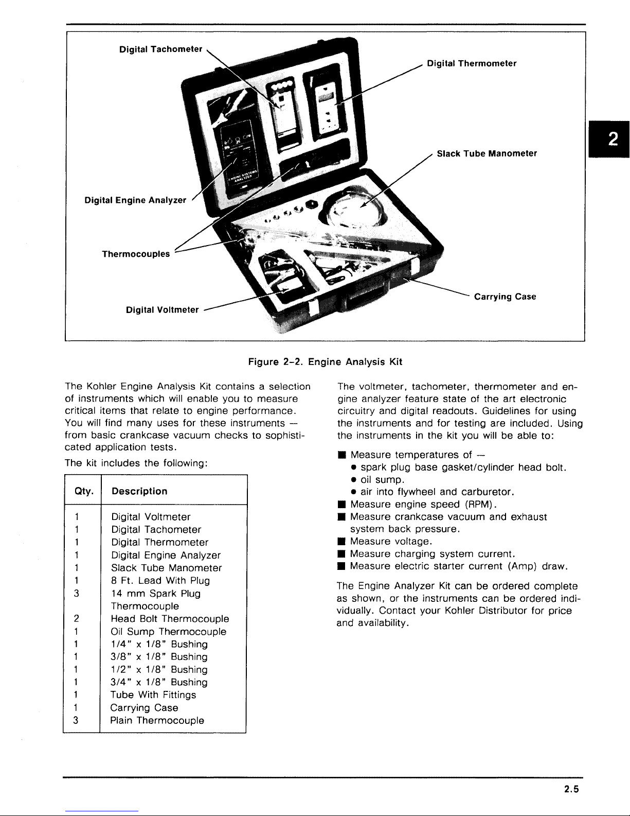
Digital
Digital
Engine
Thermocouples
Tachometer
Analyzer
Digital
Slack
Thermometer
Tube
Manometer
Digital
Voltmeter
Figure
2-2.
The Kohler Engine Analysis Kit contains a selection
of
instruments
critical
items
You will find
from
basic
cated
application
The kit includes
Qty.
1
1
1 Digital
1
1
1
3
which will enable you
that relate
many
crankcase
uses
vacuum
to
for
engine
these
checks
tests.
the
following:
Description
Digital
Digital
Voltmeter
Tachometer
Thermometer
Digital Engine Analyzer
Slack Tube
Manometer
8 Ft. Lead With Plug
mm
14
Spark Plug
to
measure
performance.
instruments
to
sophisti-
-
Thermocouple
2 Head Bolt
1 Oil
1 1
1
1
1
1
Sump
/4"
318" x 1
1/2" X 1/8"
3/4" X 1/8"
Tube With Fittings
1 Carrying
3
Plain
Thermocouple
Thermocouple
x 1
/8"
Bushing
/8"
Bushing
Bushing
Bushing
Case
Thermocouple
Engine
Analysis
The
Kit
voltmeter,
gine analyzer
circuitry
the
and digital readouts. Guidelines
instruments
feature
the instruments
• Measure
temperatures
• spark plug base
• oil
sump.
• air into flywheel and
• Measure engine
• Measure
system
crankcase
back
• Measure voltage.
• Measure charging
• Measure
electric
The Engine Analyzer Kit can
as shown,
vidually.
or
the
Contact
and availability.
tachometer,
state
and
for
testing
in
the kit you will
gasket/cylinder
carburetor.
speed
vacuum
pressure.
system
starter
instruments
your
Kohler Distributor
Carrying
thermometer
of
the
art
are
be
of
-
(RPM) .
and exhaust
current.
current
be
ordered
can
be
Case
and
en-
electronic
for
using
included. Using
able to:
head bolt.
(Amp}
draw.
complete
ordered
for
indi-
price
2.5

SECTION 3
PERIODIC MAINTENANCE
REQUIRED
These required maintenance procedures should be
MAINTENANCE
Required Maintenance
Check
Clean
Clean/Replace Fuel Filter
Clean Foam Precleaner . . . . . . . . . . . . . . . . . . . . . . . . . . . . . . . . . . . . . . . . . . . . . 25 Hours*
Change
Check Optional Reduction
Gear Unit . . . . . . . . . . . . . . . . . . . . . . . . . . . . . . . . . . . . . . . . . . . . . . . . . . . . . . . . . 50 Hours
Clean Cooling Fins and
External Surfaces . . . . . . . . . . . . . . . . . . . . . . . . . . . . . . . . . . . . . . . . . . . . . . . . . . 50 Hours*
Clean Paper Air
Cleaner Element . . . . . . . . . . . . . . . . . . . . . . . . . . . . . . . . . . . . . . . . . . . . . . . . . . 1 00 Hours*
Check Spark Plug . . . . . . . . . . . . . . . . . . . . . . . . . . . . . . . . . . . . . . . . . . . . . . . . . 1 00 Hours
Check
Clearance . . . . . . . . . . . . . . . . . . . . . . . . . . . . . . . . . . . . . . . . . . . . . . . . . . . . . . . 500 Hours
Clean Cylinder Head and
Combustion
Service Starter
Motor Drive . . . . . . . . . . . . . . . . . . . . . . . . . . . . . . . . . . . . . . . . . . . Annually
• Perform these maintenance procedures
Oil
Level . . . . . . . . . . . . . . . . . . . . . . . . . . . . . . . . . . . . . . . . . . . . . . . . . . . . . . . Daily
Grass Screen . . . . . . . . . . . . . . . . . . . . . . . . . . . . . . . . . . . . . . . . . . . . . . . . . . . . Daily*
..........................................
Oil
. . . . . . . . . . . . . . . . . . . . . . . . . . . . . . . . . . . . . . . . . . . . . . . . . . . . . . . . 25 Hours
Valve-
extremely dusty and dirty conditions.
To-
Tappet
Chamber*
..............................................
performed
more
frequently when engine is operated under
at the
frequency
stated
As Required
or
in
the table:
Frequency
500
Hours**
500 Hours
*
• 250 Hours when leaded gasoline is used.
~
WARNING: Accidental Starts!
Before
remove the spark
starting accidentally. Ground the lead to prevent
sparks that
CHECK
The
proper oil
phasized. Check oil
seNicing
OIL
importance
the engine
plug
to prevent the engine from
could
cause fires.
LEVEL
of checking and maintaining the
level in crankcase cannot be
BEFORE
or
equipment, always
EACH
USE
overem-
as follows:
1. Make sure the engine is stopped, level, and is
cool so the oil has had
sump.
2.
Clean the area around oil fill
fore removing
etc.,
out of the engine.
3. Remove
sert dipstick and push it
tube. Remove dipstick and
4.
On
engines with threaded
shoulder plug on
oil fill
to
keep dirt, grass clippings,
cap/dipstick;
top
time
to
drain into the
cap/dipstick
wipe oil off. Rein-
all the way down into
of
check
type
hole
the level.
plug dipstick,
to
observe level.
be-
3.1

The oil level should
"F"
mark
on
the
dipstick. Refer
be
up to, but not over, the
to
Figure
3-1.
Precleaner
If
so
equipped,
every
tremely
25 operating hours
dusty,
wash and reoil
(more
dirty
conditions).
the
precleaner
often
under
ex-
Figure
5. Add the
Always
adding
CAUTION:
CHANGE
For a new engine,
hours
of
thereafter.
hours
those rebuilt with a
use straight
for
the first 5 hours
after
this initial
hours
thereafter.
warm
from
carry
away
proper
check
more
oil.
Never
operate
below
stick.
"L"
OIL
operation. Change oil
For an overhauled engine
30-weight
run-in
Drain oil while the engine is still
operation. The oil will flow freely and
more
impurities. Change oil as follows:
t
Operating
Range
__l_
L
3-1.
Oil Level Range.
type
of
oil if the level is low.
the level with dipstick
the engine with the oil level
mark
or
over
"F"
change
new
of
oil
after
the first 5
every
shortblock
Service Class
operation. Change the oil
period. Change oil
or
SF
before
mark
on
dip-
25 operating
or
miniblock,
or
SG
oil
every
25
1 . Remove
the
2.
Rinse
detergent
water (do not wring).
dry.
3. Saturate
Squeeze out excess oil.
4. Reinstall
precleaner
precleaner
precleaner
are eliminated. Squeeze out excess
precleaner
precleaner
from
paper
in warm
thoroughly until all
water
Allow
precleaner
in
clean, fresh engine oil.
over
paper
element.
with
element.
detergent.
traces
to
Paper Element
Every 100
tremely
element. Replace the element as necessary.
1.
Remove the precleaner (if so equipped), element
cover, and paper element.
2.
Replace a dirty, bent,
a genuine Kohler element. Handle new elements
faces are bent
NOTE:
Reinstall the paper element.
3.
4.
Install the precleaner (cleaned and oiled) over
the
hours
dusty
carefully; do not use of the sealing sur-
Do
not wash the paper element
pressed air as this will
paper
of operation
or
dirty conditions),
or
or
damaged.
element.
(more
damaged
damage
often under ex-
check
the paper
element with
or
element.
use
Wash
of
air
com-
1. Remove
engine
better
2.
Reinstall
ened securely.
Fill with new oil
3.
mark
on dipstick
the engine is
oil.
SERVICE
K-Series
paper
also
are
which surrounds the
ure
3-2.
the
oil drain plug and dipstick. Tilt the
slightly towards the drain hole to obtain
drainage.
the
drain plug. Make sure it is tight-
of
the
on
the
AIR
engines are
air
cleaner
equipped
proper
dipstick. Always
before
adding
level when filling and checking
CLEANER
equipped
element.
with an oiled
paper
Some
element.
type
check
more
with a
specifications
foam
3.2
to the
oil. Make sure
high-density
precleaner
Refer
"F"
the level
to
Fig-
5.
Install the air cleaner
en wing nut. Make sure element is sealed tightly against air cleaner base.
cover
and wing nut. Tight-
Inspect Air Cleaner Components
Whenever the air cleaner
icing the element
components:
Air
Cleaner Base - Make sure it
carburetor
Element
New Look
is not bent
nut
is
cleaner base and
50 in. lb. torque.
Breather
cleaner base and breather
and is not
Cover
~ngines
or
secured tightly to seal
Tube
or
and
only,
damaged.
element
- Make sure it
cover
precleaner,
bent
or
Element
make
Check
element
cover. Tighten nut to
cover.
is
removed,
check
is
damaged.
Cover
sure
that element cover
is
sealed tightly
the following
secured tightly to
Nut -On
element
between air
or
serv-
K181
cover
in
air

"'--
PRECLEANER
(OPTION)
Figure
NOTE:
ponents could allow unfiltered air into the engine
causing
damaged
Damaged, worn,
premature
or
wear and failure. Replace all
worn components.
or
loose air cleaner
3-2.
Air Cleaner Components.
com-
CLEAN AIR INTAKE/COOLING AREAS
To ensure
screen, cooling fins, and other external surfaces
of engine are kept clean at
operating hours
dusty, dirty conditions), remove the blower housing and
fins and external surfaces as necessary. Make
sure the cooling shrouds are reinstalled. Refer to
the
"Disassembly"
cooling shroud removal and installation proce-
dures.
NOTE:
screen, dirty
ing shrouds removed
due to overheating.
proper
other
Operating the engine with a blocked grass
cooling, make sure the grass
all times. Every 50
(more
cooling shrouds. Clean the cooling
or
plugged cooling fins,
often under extremely
and "Reassembly" sections
and/or
will cause engine damage
cool-
CHECK SPARK PLUG
for
Ground Electrode
Figure
1 . Before removing spark plug, clean the area
around the base of plug to keep dirt and debris out of engine.
3-3.
Servicing Spark Plug.
Every 1 00 operating hours, remove the spark plug,
check
new plug as necessary. Refer
its condition, and reset gap
to
or
replace with
Figure
3-3.
2. Remove the plug and
place the plug if worn
able.
check
or
its condition.
if reuse is question-
Re-
3.3

NOTE: Do not clean the spark plug
using abrasive grit.
spark plug and
wear and
3.
Check
gap by
enter
damage.
gap
using a wire feeler gauge. Adjust
carefully bending the ground electrode.
Some
grit could remain
the engine causing extensive
in
a machine
in
4. Reinstall
plug
spark
to
18/22 ft. lb.
plug into cylinder head. Torque
SERVICE OPTIONAL REDUCTION GEAR
UNIT
On
engines
check
hours. Refer
equipped
the oil level
to
Figure
with a reduction
in
unit
every
3-4.
gear
50 operating
unit,
Figure
3-5.
In-line
Fuel Filter.
SERVICE STARTER MOTOR DRIVE
Every 500 operating hours
occurs
of
1. Remove
2. Remove dust
first) , clean and lubricate the drive splines
the Bendix-drive
starter
propriate
spacer, spring, dust
pinion.
electric
from
"Disassembly"
cover,
or
annually (whichever
starter
crankcase. (Refer
stop nut, stop gear
cover
motor.
section.)
spacer, and drive
to
ap-
Drain Plug
(Oil Level
Figure
1 . Remove the plug on the lower part of
cover.
to the
2.
To add oil,
of
top
used
3.
Reinstall and tighten the plugs securely.
3-4.
Reduction Gear Unit.
With engine level, the oil should be up
bottom
the unit. Use the
in
of
the plug hole.
remove
the engine crankcase.
the vented fill plug at the
same
type of oil as
Check)
gear
unit
CHECK FUEL FILTER
Some
filter. Visually
to
engines are equipped with
inspect the filter periodically. Re-
place when dirty with a genuine Kohler filter. Refer
Figure
3-5.
an
in-line
fuel
3.
Clean the drive shaft splines with solvent. Dry
solvent thoroughly.
4.
Apply a small
drive
lubricant (Part No.
NOTE: Kohler
357 01) must be used on all Kohler
drives. The use
drive to stick
5.
Apply a small
stop nut threads. Assemble drive parts
verse
6. Reinstall
order
160 in. lb.
priate
"Reassembly"
amount
starter
of
other
or
bind.
amount
of
removal. Torque stop nut
starter
to
of
Kohler
52
drive lubricant (Part No.
lubricants can cause the
of
Loctite®
crankcase. (Refer
section.)
electric
357 01)
electric
No.
to
splines.
271
in
to
starter
52
starter
to
re-
to
appro-
CLEAN CYLINDER HEAD AND COMBUSTION CHAMBER
Every 500 operating hours (250 hours when leaded
gasoline is used) ,
combustion
remove
chamber.
cylinder head and clean
Refer to Figure
3-6.
3.4

~1
Figure
1 . Remove the cylinder head baffle and cylinder
head.
2. Clean away
wooden
3. Reinstall the cylinder head using a new gasket.
Torque the cylinder head fasteners
quence
CHECK
Every 500 operating hours,
cover
flat feeler gauge. Refer to Figure
must
1 . Remove the air cleaner assembly, carburetor,
and
"Disassembly"
2.
Position the crankshaft so the piston
of
tappets).
3-6.
Cleaning Cylinder Head And
Combustion Chamber.
combustion
or
plastic scraper.
to
the values specified
VALVE-
and
check
be cold when checking this clearance.
breather
compression
TO-
valve-to-tappet
assembly. (Refer
section.)
stroke
deposits using a
TAPPET
remove
(cam
has no
in
se-
in
Figure
CLEARANCE
breather/valve
clearance with a
3-8.
The engine
to
appropriate
is
effect
3-7.
at top
on
K161, K181 •
15-20
0)2
7©8Q)14(Q)
Q)
©
3
Q5
K241,
K301, K321
25-30
ft. lbs.
9
©
ft. lbs.
~6
Figure
3-8.
Measuring ValveClearance.
To-
Tappet
Q)
3
g5
* Includes
Figure
3-7.
K341
25-30
ft. lbs.
g2
K141
Cylinder Head Fastener
Tightening Sequence.

3. Measure
valve-to-tappet
clearance with a flat
feeler gauge.
On
Model
clearance is too small,
grind the valve
K91, K141, K161,
remove the valves and
stems
until the
K181
correct
-If
the
clearance is obtained. Make sure valve stems are
ground perfectly flat and smooth.
Model Intake Valve Exhaust Valve
K91
K161,K181
K241,
K321,
If
K301
K341
clearance is too large, replace the valves and
Figure
.005" I .009"
.006" I .008"
.008" I .01
3-9.
0"
Valve Clearances
.011
"/.015"
.017"/.019"
.017"/.019"
recheck clearance.
NOTE:
grinding the valves
the
for
On
Large clearances can also be reduced by
and/or
valve seats. Refer to
"Inspection And Repair/Reconditioning" section
valve specifications.
Models
K241, K301, K321,
K341
- Adjust the
clearance by turning the adjusting screw on tappets. Refer to Figure
3-9.
STORAGE
If the engine will be out
mately two months
storage procedure.
1 . Change the oil when engine is still warm from
operation. Refer to "Change
2. Change the oil
equipped. Refill with the
engine crankcase
fer
to "Service Optional Reduction Gear Unit. "
Run
engine
for
clean oil throughout engine.
3. Drain the
fuel tank and fuel system (or run
engine until fuel tank and fuel system are
empty).
4. Remove the spark plug. Add one tablespoon
of engine oil into the spark plug hole. Install
by do not connect plug lead. Crank the
plug,
engine two
or
5. Remove the spark plug. Cover the spark plug
with
hole
thumb
piston is at the top of its stroke (pressure
against thumb is greatest).
do not connect plug lead.
of
service
or
more,
use the following
Oil."
in
reduction
gear
same
for
season of operation. Re-
a few minutes
to
three revolutions.
and turn engine
Reinstall plug, but
for
approxi-
unit, if so
oil as used
distribute
over
until the
in
Figure
3-10.
Clearance Through
Adjusting
K341.
Valve-
Models
To-
Tappet
K241
6. Clean the exterior surfaces of engine. Spread
a light film of oil over any exposed metal surfaces of engine to prevent rust.
7. Store the engine
in
a clean, dry place.
3.6

SECTION 4
TROUBLESHOOTING
TROUBLESHOOTING
When trouble occurs, be sure to
causes which, at first,
be considered. For example, a starting problem
could be caused
Some
listed below. Use this as a guide to locate trouble
causing factors.
Engine Cranks But
1 . Empty fuel tank.
2. Fuel shutoff valve closed.
3. Clogged fuel line.
4. Spark plug lead disconnected.
5. Keyswitch
6. Faulty spark
7. Faulty ignition.
8. Dirt
Engine
1 . Restricted
2. Dirt
3. Faulty choke
4. Loose wires
5. Carburetor improperly adjusted.
6. Faulty cylinder head gasket.
7. Faulty fuel pump.
Engine
1 . Hydrostatic transmission not
2. Loose wires
3. Dirt
4.
5. Faulty choke
6. Faulty spark plug.
7. Carburetor improperly adjusted.
8.
9. Low compression.
10. Faulty
Engine Will Not Crank
1 . Hydrostatic transmission is not
common
or
water
Starts
or
water
ground.
Starts Hard
drive is engaged.
or
water
Clogged
Incorrect
ACR
drive is engaged.
by
causes
or
kill switch
plug.
in
But
Does Not Keep Running
fuel tank vent.
in
or
or
or
in
or
restricted fuel lines.
or
valve-to-tappet
mechanism.
GUIDE
check
may
seem too obvious to
an
empty
of
Will Not Start
fuel system.
fuel system.
throttle controls/cables.
connections shorting ignition to
connections.
fuel system.
throttle controls/cables.
fuel tank.
engine troubles are
in
"off"
in
clearance.
the simple
position.
neutrai/PTO
in
neutrai/PTO
2. Battery is discharged.
3. Safety interlock switch is
or
4. Loose
5. Faulty keyswitch
6. Faulty electric starter/starter solenoid.
7. Retractable starter not engaging
8. Seized internal engine components.
Engine Runs
1 . Dirt
2. Spark plug lead loose.
3. Loose wires
ing ignition to ground.
4. Carburetor improperly adjusted.
5. Engine overheating.
6.
Incorrect
Engine Will Not Idle
1 . Idle speed adjusting screw improperly set.
2. Dirt
3. Idle fuel adjusting screw improperly set.
Fuel tank vent restricted.
4.
5. Faulty spark
6. Incorrect
7. Low compression.
Engine Overheats
1 . Grass screen, cooling fins
clogged.
2. Excessive engine
3. Low crankcase oil level.
4. High crankcase oil level.
5. Carburetor improperly adjusted.
Engine Knocks
1 . Low crankcase
2. Excessive engine load.
Engine Loses Power
1 . Low crankcase oil level.
2. High crankcase oil level.
3. Restricted air cleaner element.
4. Dirt
5. Excessive engine load.
6. Engine overheating.
7. Faulty spark
8. Carburetor improperly adjusted.
faulty wires
But
or
water
valve-to-tappet
or
water
valve-to-tappet
or
water
plug.
or
Misses
in
fuel system.
or
connections intermittently short-
in
fuel system.
plug.
load.
oil level.
in
fuel system.
"engaged"
or
connections.
ignition switch.
in
clearance.
clearance.
or
shrouding
.
drive cup.
II
4.1

9. Low compression.
Engine Uses Excessive Amount of Oil
1. Incorrect oil viscosity
or
2. Clogged
system.
3. Worn
4. Worn cylinder bore.
5. Worn valve
improperly assembled breather
or
broken piston rings.
stems
or
and/or
type.
guides.
EXTERNAL ENGINE INSPECTION
0 Before cleaning
check
This inspection can give clues to what might
be found inside the engine (and the cause)
once
its external appearance and condition.
it is disassembled.
or
disassembling the engine,
CLEANING THE ENGINE
After inspecting the external condition of the engine, clean it thoroughly before disassembling.
Also clean individual components as the engine is
disassembled.
inspected and gauged
There are many commercially available cleaners
that quickly remove grease, oil and grime from
engine parts. When such a cleaner is used, follow
the
manufacturer's
sure all traces of the cleaner are removed before
the engine is reassembled and placed
tion. Even small amounts of these cleaners quickly
break down the lubricating properties of engine oil.
BASIC ENGINE
Only clean parts can be accurately
for
wear
or
damage.
instructions carefully. Make
in
opera-
TESTS
for
0 Check
crankcase, cooling fins, grass screen and
other external surfaces. Dirt or debris
areas are causes of overheating.
0 Check
aged components. Excessive oil leakage can
indicate a clogged
breather, worn
or
loose
0 Check the air cleaner cover, element cover
and air cleaner base
of improper fit
0 Check the air cleaner element. Look for holes,
tears, cracked
other damage that could allow dirt to enter the
engine. Also note if the element is clogged
restricted. These conditions could indicate that
the air cleaner has been underserviced.
0 Check the carburetor throat for dirt. Dirt
throat is further indication that the air cleaner
is not functioning properly.
0 Check the oil level. Note if the oil level
within the operating range
it is low
0 Check the condition
into a container - it should flow freely. Check
for
metal chips and other foreign particles.
NOTE:
away from the workbench.
time
Sludge is a natural
small accumu_lation
formation could indicate that the oil has not been
changed as
weight
settings
It
for
of
buildup of dirt and debris on the
in
these
for
obvious fuel and oil leaks and
or
improperly assembled
or
damaged seals and gaskets
or
improperly torqued fasteners.
for
damage
or
seal.
or
damaged sealing surfaces or
on
or
overfilled.
of
the oil. Drain the oil
is good practice to drain oil at a location
Be
sure to allow ample
complete
oil has been used,
or
weak ignition, to name a few.
drainage.
by-product
is
normal. Excessive sludge
recommended,
of combustion; a
an
over-rich
or
the dipstick,
incorrect type or
dam-
indications
in
is
or
carburetor
or
the
Fuel System Test
To
determine if fuel is getting
disconnect the fuel line at inlet to carburetor - if
fuel does not flow out of line,
to tank
cap, blocked filter screen, faulty fuel pump, etc.
fuel is getting as far as the carburetor, remove
the spark plug, crank engine and
inside combustion chamber.
here, check
for
clogged lines, wrong (unvented) filler
for
faulty carburetor.
to
the carburetor,
check
If
system back
check
no fuel is present
for
If
fuel
Ignition System Test
To determine if the ignition system is good, re-
move the spark plug and place plug with side
electrode against cylinder head then crank engine
at sufficient speed to produce a good spark.
sharp, snappy spark is noted, this eliminates the
ignition system components as the cause, al-
though the ignition timing could be off.
If
no spark
the ignition system further. If points are pitted,
don't
bad shape. Dirty points may be cleaned. A bad
condenser will cause premature failure of points.
if
Check the breaker push rod
ing
or
can be tested on commercial
manufacturer's instructions. Check ignition coil
coil tester for continuity.
or
a weak spark is produced,
attempt
sticking - replace as needed. Condenser
to service them - replace points
for
evidence of bind-
tester
per tester
If
check
a
in
on
Crankcase Vacuum
A partial vacuum should exist
when the engine is operating at normal temperatures. Pressure
by a clogged or improperly assembled breather)
can cause oil to be forced out at oil seals, gaskets
or
other available spots.
Crankcase vacuum is best measured with a slack
tube manometer. The
in
the crankcase (usually caused
manometer
in
the crankcase
included
in
the
4.2

Kohler Engine Analysis Kit is
to
the
"Special
tion.
Tools"
section
Crankcase Vacuum Test
recommended.
for
more
informa-
Refer
side.
If
there
side is the
pressure
engine side)
following table.
same
(level
check
is no
vacuum
as in open side)
in
open side is higher than
for
(level
the conditions
in
engine
or
a positive
in
in
the
To
test
crankcase
1. Insert the
Leave the
to
the
atmosphere.
clamp
2.
Start the engine and run at high speed (3200
to 3600
3.
Open the
the
be 5
1.
Crankcase
2.
Seals
improperly
3.
Piston
inspecting
is closed.
RPM)
tube.
to
1 0 inches above the level
and/or
blowby
vacuum
stopper
other
vent
.
clamp
The level
and note the water level
Possible Cause
breather
gaskets leaking. Loose
torqued
or
leaky valves.
components.)
with the
hose into the oil fill hole.
of
the
manometer
Make sure the shutoff
in
the engine side should
NO
CRANKCASE VACUUM/PRESSURE
clogged
fasteners.
or
manometer:
in
inoperative.
or
(Confirm
open
in
the open
by
4. Close the shutoff
engine.
clamp
before
Compression Test
Because these engines are
matic
compression release
difficult
ing.
To
and related
crankcase
1.
Disassemble breather, clean parts
reassemble, and recheck pressure.
2.
Replace all
Make sure fasteners are
appropriate
necessary.
3.
Recondition
and valve guides.
to
check
obtain an
the condition
mechanisms,
vacuum
IN
CRANKCASE
worn
torque
piston, rings,
accurate
test
Solution
or
damaged
values and sequences when
equipped
mechanism
of
the
physical inspection and a
are
recommended.
tightened
cylinder
shutting
with an auto-
compression
combustion
thoroughly,
seals and gaskets.
securely. Use
bore, valves,
off
(ACR), it is
read-
chamber
the
II
4.
Restricted exhaust.
MEASURE
BETWEEN
DIFFERENCE
COLUMNS
Figure
4.
Replace restricted
4-1.
muffler/exhaust
system.
Figure
4-2.
"U"
Tube
Manometer
4.3

SECTION 5
AIR CLEANER AND AIR INTAKE SYSTEM
K series engines are equipped with a
paper air
fications are also equipped with
precleaner that surrounds the paper element. Re-
fer
cleaner
to Figure
5-1.
element.
Engines of
high-density
an
oiled foam
some
speci-
AIR CLEANER DISASSEMBLY
1 . Remove the wing nut and air cleaner cover.
2.
Remove the precleaner (if so
per
element
3. Remove the base screws, air cleaner base,
gasket and hose.
and seal.
equipped),
pa-
AIR CLEANER SERVICE
Precleaner
If
so equipped, wash and
every 25 operating hours
tremely
1 . Wash the precleaner
2. Rinse the precleaner thoroughly
3. Saturate the precleaner with
4. Reinstall the precleaner
dusty
or
dirty conditions).
gent.
detergent
of
cess water (do not wring).
dry.
gine
oil. Squeeze out excess oil.
ment.
are eliminated. Squeeze out ex-
re-oil
the precleaner
(more
in
often under ex-
warm water and
Allow precleaner to
clean, fresh en-
over
the
deter-
until all traces
paper
ele-
II
Figure
5-1.
Air
Cleaner
"'------
Assembly
PRECLEANER
- Exploded View.
(OPTION)
5.1

Paper Element
Inspect Air Cleaner Components
Every 1 00 operating hours
tremely
element. Replace
1 . Remove the precleaner (if so equipped), ele-
2.
NOTE:
compressed
3. Reinstall the
4.
5.
dusty
or
dirty conditions)
the
ment
cover
ment.
Replace a dirty, bent
new genuine Kohler
elements carefully;
bent
or
Do not wash the paper element or use
Install the precleaner (cleaned and oiled) over
the paper element.
Install the air cleaner
Tighten wing nut. Make sure element
tightly against air cleaner base.
nut, element cover and paper ele-
damaged.
air as this will damage the element.
paper
(more
element
or
element.
do
not use if surfaces are
element.
cover
often under ex-
check
as follows:
damaged
Handle new
and wing nut.
element with a
the
is
paper
sealed
Whenever the air cleaner
when servicing the paper element
check
1 .
2.
3. Breather
NOTE:
tain specifications, the element
the breather tube, making it impossible
crankcase vacuum.
the end of the breather tube that protrudes
through the air cleaner base at approximately a 45
degree angle.
the following components:
Air
Cleaner Base - Make sure it is secured
tightly to carburetor and is not bent
aged.
Element
K181
ment
that element
seal element between air cleaner base and
element cover. Tighten nut
torque. Refer to Figure
in
the air cleaner base and breather cover.
Cover and
New Look engines only, make sure ele-
cover
is not bent
cover
Tube
- Make sure it is sealed tightly
On
Model
K181
cover
is removed,
or
precleaner,
or
Element
nut is secured tightly
Cover
or
damaged. Check
to
Nut -On
50 in. lb.
5-2.
New Look engines of
cover
may
to
To
prevent this problem, cut
or
dam-
to
cer-
contact
maintain
Air
Cleaner
Cover
~
Figure
5.2
5-2.
K181
New Look,
Air
Cleaner
Assembly.
Air
Cleaner
Base
Breather
Hose

NOTE:
ponents
causing
damaged
OPTIONAL OIL BATH
If
clean and
tion
to Figure
1 . Remove the
2.
NOTE: Do
ment. The filtering material could be damaged.
3. Lightly
4. Inspect base and
Damaged, worn
could
premature
the engine has an oil bath type air cleaner,
or
more
bowl and drain the oil
Thoroughly wash bowl and
vent.
low it
damaged.
allow unfiltered air into the engine
or
worn
service
frequently if conditions warrant. Refer
5-3.
cover,
Swish the
to
dry.
not
use
re-oil
the
or
loose air cleaner
wear and failure. Replace all
components.
AIR
CLEANER
it
after
every
lift the element out
element
compressed
element
cover
25
hours
of
from
the bowl.
cover
in
clean sol-
in
the solvent and al-
air to dry the ele-
with engine oil.
gaskets. Replace if
of
com-
opera-
the
5. Install base gasket and place filter on air horn.
6.
Add engine oil
mark.
7.
Install filter
Secure with wing nut finger tight only.
COOLING
Effective cooling
on an unobstructed flow
fins. Air is drawn into the cooling shroud
located on the flywheel. The blower housing, cool-
ing shroud, air screen covering the flywheel and
cooling fins on the cylinder and cylinder head
be kept clean and unobstructed at all
Never operate the engine with the blower housing
or
cooling shroud-removed. These devices direct
air flow
NOTE:
some
and
able unless other modifications are
engine.
AIR
over
Some
use metal. The two are
to
filter and fill
element,
cover
to
the
OIL
LEVEL
gasket and cover.
INTAKE SYSTEM
of
an air cooled engine depends
of
air
over
the cooling
by
fins
times.
the cooling fins.
engines use a plastic grass screen
not
interchange-
made
to
the
must
II
OIL LEVEL
Figure
5-3.
Optional Oil Bath Air Cleaner.
5.3

SECTION 6
FUEL
SYSTEM AND GOVERNOR
FUEL SYSTEM - GASOLINE
The typical gasoline fuel
ponents include the fuel tank with vented cap,
shutoff valve with screen,
pump
(some
models),
necting fuel line.
system
in-line
carburetor
and related
fuel filter, fuel
and intercon-
Operation
The fuel
screen and shutoff valve,
lines by the fuel
Fuel enters the
into the
The
from
carburetor
fuel-air
the tank
pump
carburetor
is
moved
in-line
through the
filter and fuel
(if so equipped)
float bowl and
body
where it is mixed with air.
or
gravity.
is
moved
mixture is drawn into the combustion
com-
chamber
where it is
compressed,
then ignited by
the spark plug.
Troubleshooting
Use the following
reaching the combustion
~
WARNING: Explosive Fuel!
Gasoline may be present in the carburetor and fuel
system. Gasoline is extremely flammable and
explode
if
ignited. Keep sparks, open flames, and
other sources
connect and ground the spark
the possibility
procedure
to
check
that fuel is
chamber.
of
ignition away from the engine. Dis-
plug
lead to prevent
of
sparks from the ignition system.
it
can
II
Test
Check
1 .
A.
B.
C. Make sure the fuel
Check
2.
A.
B.
C.
D.
3.
Check
A.
B.
4.
Check
A.
B.
for
the
following:
Make sure
Make sure
Disconnect the spark plug lead.
Close the choke on
Crank
Remove the spark plug and check
Remove fuel line
Hold line below
valve and observe flow.
Remove fuel line
Crank engine several times and observe flow.
the
tank contains fuel.
the
fuel
for
fuel
In
the
the engine several
for
fuel
flow
from
from
bottom
operation
of
fuel
from
cap
vent
is
shutoff
valve
combustion
carburetor.
times.
tank
inlet fitting
of
tank. Open
pump
inlet fitting
open.
to
is
fuel
open.
chamber.
for
fuel
pump.
at
fuel pump.
shutoff
at
carburetor.
at
tip.
If
there
2.
bust ion
If
there
fuel tank.
3.
If fuel
does
(Test
4).
If fuel
does
vent,
shutoff
If
the fuel tank
the tank, modify
1/32"
to
If fuel
4.
does
line
Is
unobstructed,
placed.
If fuel
does
faulty. Refer
Is fuel
at
chamber.
Is
no
fuel
(Test
flow
not
valve
cap
1 I 1 6"
off
not
flow
to
Conclusi~n
tip
of
spark plug, fuel
at
tip
of
3).
from
flow
screen,
the
the
flow
from
the
spark plug, check
line, check
from
line, check
and fuel lines.
vent does not allow air
vent
for
proper
bottom.
from
fuel
fuel line, the
"Carburetor"
Refer
line, check
pump
Is
is
reaching
for
for
faulty fuel pump.
for
clogged fuel tank
to
operation by cutting
to
faulty and
carburetor
portion
escape
Figure 6-1 .
for
clogged fuel line. If
must
probably
of
this section.
fuel
be
the
from
re-
com-
the
from
Is
6.1

Cut Off
1/32"-1/16"
Operation
The mechanical fuel
that rides on the engine camshaft. The
transmits a pumping action to the flexible diaphragm inside the
tion draws fuel in through
the downward stroke of the diaphragm.
upward stroke, the
outlet
check
valve. Refer
pump
is operated by a lever
lever
pump
body. The pumping
the
inlet
check
fuel is forced out through the
to
Figure
valve on
On
6-2.
ac-
the
Figure
6-1.
("New
Fuel
Look"
Tank
Only)
Cap.
FUEL TANK
Engine-mounted
are
constructed
vented cap. The venting properties of the cap
should be
cause pressure buildup
result
is
loosened.
the tank, stopping the engine.
Fuel
Some
valve with a wire mesh screen.
a shutoff valve, a straight outlet fitting is used.
The wire
the tank
valve permits work on the fuel system without the
need
checked
in
fuel spraying
Shutoff
engines are equipped with a fuel shutoff
mesh
from
for
draining the tank.
fuel tanks on K series engines
of
steel. They are fitted with a
regularly. A clogged vent can
in
the tank, which could
from
the filler when the cap
It
can also cause a partial vacuum
Valve
On
engines without
prevents relatively large particles
reaching the carburetor. The shutoff
FUEL FILTER
Some engines covered by this manual
equipped with a
When
the
interior of the filter appears
it should
be
see-through
replaced.
in
line fuel filter.
may
to
be dirty,
be
FUEL PUMP
All K series engines except the
for
sions
pump.
gines, a
pad on the crankcase.
Older fuel
els have a
better
mizing the
mounting a mechanically operated fuel
If
no fuel
cover
pumps
insulates the fuel
pump
is placed over the
body
made
chance
is mounted on these en-
have a metal body. Later
of plastic. The plastic body
of
vapor
from
K91
have provi-
pump
mounting
mod-
the hot engine, mini-
lock.
in
in
Figure
6-2.
Mechanical
Fuel
Pump.
Removal
1 . Disconnect the fuel lines
outlet fittings
2. Remove the fillister head
washers, fuel
3.
If
required, remove the fittings
body.
of
the
pump
from
the inlet and
pump.
sems
and gasket.
screws, flat
from
the pump
Repair
Plastic bodied fuel
must be replaced when faulty. Replacement
pumps are available
pump, mounting gasket and
pumps
are not serviceable and
in
kits which include the
plain washers.
Installation
1 . Fittings - Apply a small amount
Aviation Perm A Gasket (or equivalent gasoline
resistant thread sealant)
in
to
pump
the
Figure
same
tings into
fittings
rection is reached.
Install new gasket, fuel
2.
lock washers and
Refer
six
fillister head
6-3.
to
full
turns;
direction until desired di-
pump,
of
Permatex®
fittings. Turn fit-
continue turning
flat washers,
sems
screws.
6.2

Plain Washer (2)
~
-----
~~
,:IJ..
Fillister Head Sems
L
Screws
Figure
NOTE:
tioned above the
pump
sult if the lever
Make sure that the flat washers are installed next
to the mounting flange
the lock washers.
If
bodied
is discarded and the new thin gasket
3. Torque screws to
4. Connect fuel lines
Make sure that the fuel
and severe
a metal bodied
pump,
make
(2)
6-3.
Installing Fuel Pump.
camshaft.
damage
is
positioned below the camshaft.
to
pump
was replaced by a plastic
sure that the old thick gasket
37 - 45
to
inlet and outlet fittings.
\Fuel
pump
Damage to the fuel
to the engine could re-
prevent
in.llb.
CARBURETOR -GASOLINE
Pump
Mounting
lever
damage
is
used.
Flange
is
posi-
from
tor. This gives a
the adjusting needles out (counterclockwise) increases the supply
gives a
dles midway between the lean and rich positions
will usually give the best results. Adjust the carburetor as
1 . With the engine stopped, turn the low idle fuel
NOTE:
adjusting needles are tapered
Damage to the needles and the seats
body will result if the needles are
2.
3. Start the engine and run at half throttle
4. High Idle Fuel Needle Setting: This adjustment
Place the throttle into the
ble, place the engine under load.
Turn the high idle fuel adjusting needle out (counterclockwise)
engine speed
of the needle.
richer
follows:
adjusting needle
lightly.
The tip
Preliminary Settings: Turn the adjusting needles
out (counterclockwise)
according to the table shown
to ten minutes to warm up. The engine must
be warm before making final settings (Steps 4,
5,
6,
and
is
required only
jet
carburetors.
jet
main
leaner
fuel-to-air
of
the low idle fuel and high idle fuel
7).
type,
from
decreases
fuel-to-air
of
fuel
to
mixture. Setting the nee-
in
(clockwise) until it
from
for
adjustable high idle (main)
If
the
carburetor
go
to
step 5.
"fast"
the preliminary setting until the
(rich}. Note the position
mixture. Turning
the carburetor. This
to
critical dimensions.
in
forced.
lightly
bottomed
in
Figure
is
a fixed
position.
bottoms
carburetor
6-4.
for
five
If
possi-
II
•
£ WARNING: Explosive Fuel!
Gasoline may
system. Gasoline is extremely flammable
explode
other sources
connect
the possibility
Adjustment
The
carburetor
fuel/air mixture
conditions. Carburetors are set at the
normally
exhibits conditions like those found
that
follows, it
carburetor.
In
general, turning the adjusting needles in (clock-
decreases
wise)
be
present in the carburetor
if
ignited. Keep sparks, open flames, and
of
ignition away from the engine. Dis-
and
ground the spark
of
sparks from the ignition system.
is designed to deliver the
to
the engine under all operating
do
not need adjustment.
may
be necessary to adjust the
the supply of fuel to the carbure-
plug
and
fuel
and
it
can
lead to prevent
correct
factory
If
the engine
in
the table
and
Now turn the adjusting needle
may
engine speed
as the needle
of the needle.
Set the adjusting needle midway between the rich
and lean settings. See Figure
5. Low Idle Speed Setting: Place the throttle control into the
low idle speed to
by turning the low idle speed adjusting screw
in
or out. Check the speed using a
ter.
NOTE:
application. Refer to the
instructions
The
gines
setting the low idle fuel needle, the low idle speed
must not exceed
The actual low idle speed
for
recommended
is
1200 rpm. To ensure best results when
increase, then it will
is
turned
"idle"
specific low idle speed settings.
1500
in
or
1200
low idle speed
rpm.
in
(clockwise). The
decrease
(lean). Note the position
6-5.
"slow"
equipment
position. Set the
rpm*
( +
or
depends
manufacturer's
for
- 75 rpm)
tachome-
on the
Basic En-
6.3

PRELIMINARY SETTINGS - K-SERIES MODELS
KOHLER
Low
K91
K141
K161*
K181*
K241
K301
K321
K341
6. Low Idle Fuel Needle Setting: Place the throttle
into the
Turn the
terclockwise)
engine speed decreases (rich). Note the position
of the
Now turn the adjusting needle in (clockwise). The
engine speed
as the
of the
Set
the adjusting needle
lean settings. See Figure
and
"idle"
low idle fuel adjusting needle
from
needle.
may
needle is turned in (lean). Note the position
needle.
1-1/2
1-1/2
1-1/2
1-1/4turns
2-1/2
2-1/2
2-1/2
2-1/2
• Includes
Figure
or
6-4.
"slow"
the preliminary setting until the
increase, then it will decrease
midway
ADJUST
Idle High Idle Low Idle
turns
turns 3 turns
turns
turns 2 turns
turns 2 turns
turns
turns
"New
Preliminary
position.
between the rich
6-5.
Look"
ABLE
2 turns
3 turns
2 turns
3-1/4
3-1/2
Models
Low
out
(coun-
JET
turns
turns
Idle And High Idle Fuel Needle
WALBRO
2. Remove the
3. Remove the
4. Further disassembly
FIXED
NOT
NOT
NOT
2-1/2
1-1/4
1-1/4turns
1-1/2
1 turn
baffle
ket. Remove the
ing
speed adjusting
choke shafts is
parts are
and Choke Shaft Replacement" later
section.
JET
APPL.
APPL.
APPL.
turns
turns
turns
gasket and bowl gasket.
needles and springs. Remove the idle
to
NOTE: Refer
tion TP2377B Carburetor
Reference Manual for
additional information.
Settings.
float pin, float, fuel inlet needle,
fuel inlet seat and inlet seat gas-
idle fuel and main fuel adjust-
screw
recommended
be replaced. Refer
and spring.
to
to
publica-
remove the throttle and
only if these
to
"Throttle
in
this
7. Recheck the low idle speed using a
ter. Readjust the speed as necessary.
Adjust
Midpoint
Figure
6-5.
To
Optimum
Low
Idle Fuel
tachome-
Lean
Setting.
Disassembly
(Refer
1 . Remove the bowl retaining screw, retaining
to
screw
Figure
gasket and fuel bowl.
6-7)
Idle
Speed
Screw
Figure
6-6.
Kohler-Built
Carburetor.
Main Fuel
~Needle
Adjustable
Jet
6.4
 Loading...