

Page 1
KDI 3404TCR-SCR
OWNER MANUAL
Page 2
REGISTRATION OF MODIFICATIONS TO THE DOCUMENT
Any modifications to this document must be registered by the drafting body, by completing the following table.
Released by Document code
Technical
Documentation
ED0053032140 51534 3 2 06/2017 11/2018
Data reported in this issue can be modified at any time by KOHLER.
Model
N°
Edition Revision Issue date
Review
date
Translated from the original manual in Italian language.
Edited by Endorsed
Technical
Documentation
Important
Connect to http://iservice.lombardini.it and download the latest version of this manual onto your device.
NOTE: you can select the desired language before downloading the manual, as shown in the figure below.
The online manuals are provided with hyperlinks which direct you to each individual chapter. By clicking on;
- The analytic index titles you can go directly to the selected subject.
- The blue underlined words you can go directly to a paragraph, a table or a picture.
- The chapter titles (headings) you come back automatically to the chapter initial page.
- Clicking next to the bottom page number you come back to the analytic index.
2
EN
ED0053032140
_02
Page 3

INDEX
1 - GENERAL INFORMATION
1.1 Manual's Purpose ............................................................4
1.2 Glossary and Definitions
1.3 Emission-Related Installation Instructions
1.4 Service request
1.5 Manufacturer and engine identification
1.6 Engine component identification
1.7 Cooling circuit
1.8 AdBlue circuit
1.9 Intake and exhaust circuit............................................10
1.10 Homologation labels
1.10.1 Label for EPA rules
1.10.2 Label for China Standards
1.10.3 Label for Korea Standards
...............................................................4
.................................................................8
..................................................................9
................................................4
..................4
.......................5
..................................6
...................................................11
................................................... 11
......................................12
......................................13
2 - TECHNICAL INFORMATION
2.1 General description of the engine ..............................14
2.2 Engine specifications
2.3 Engine dimensions (mm)
2.4 Oil....................................................................................15
2.5 Fuel
2.5.1 Fuel for low temperatures.........................................17
2.5.2 Biodiesel fuel
2.5.3 Synthetic fuels: GTL, CTL, BTL, HV
2.5.4 Emission-Related Installation Instructions
2.6 AdBlue
2.7 Coolant recommendation
2.8 Battery recommendation
2.9 Inducement strategy of SCR system
.................................................................................16
............................................................................18
...................................................14
..............................................14
.............................................................17
.........................17
............17
............................................19
.............................................19
..........................20
4 - INFORMATION ABOUT USE
4.1 Pre-start check .............................................................26
4.2 Running-in period
4.3 Starting and turning off
4.3.1 Starting
4.3.2 After starting
4.3.3 Turning off
4.4 Refuelling
4.5 Oil filling
4.6 Coolant filling
4.7 AdBlue® filling
.......................................................................26
.......................................................................27
.........................................................................27
.........................................................26
...............................................26
.............................................................26
..................................................................26
................................................................28
..............................................................28
5 - INFORMATION ABOUT MAINTENANCE
5.1 Useful information about maintenance ......................29
5.2 Periodic maintenance
5.3 Oil level check
5.4 Air filter check
5.5 Check of the radiator heat - exchanger surface
5.6 Rubber hoses check
5.7 Check coolant level.......................................................32
5.8 Check Poly-V alternator belt
5.9 Filter cartridge and fuel pre-filter check
5.10 Product preservation
5.11 Engine storage up to 6 months
5.12 Engine storage over 6 months
5.13 Engine starting after storage.....................................34
5.14 Unused machine..........................................................35
5.14.1 Operations for the engine
5.14.2 Operations for the SCR system
...............................................................30
...............................................................31
..................................................29
.......32
.....................................................32
.......................................33
....................33
..................................................34
..................................34
...................................34
.......................................35
..............................35
3 - SAFETY INFORMATION
3.1 Safety information ........................................................21
3.2 General remarks
3.2.1 Note for OEM
3.2.2 Note for end user
3.3 Safety signal description
3.3.1 Adhesive safety plates
3.3.3 Warnings
3.3.2 Safety guards
3.4 Information and safety signals
3.5 Safety and environmental impact
3.6 Location of safety labels on engine
...........................................................21
..............................................................21
.......................................................21
.............................................23
..............................................23
.....................................................................23
.............................................................23
....................................24
...............................24
............................25
6 - INFORMATION ABOUT REPLACEMENTS
6.1 Engine oil replacement ................................................36
6.2 Oil filter cartridge replacement...................................37
6.3 Fuel filter and pre-filter cartridge replacement
6.4 Air filter cartridge replacement
6.5 Replacement of AdBlue® filter
6.6 Disposal and scrapping
................................................39
..................................38
...................................39
........38
7 - INFORMATION ABOUT FAILURES
7.1 U seful information about failures ................................40
8 - INFORMATION ABOUT WARRANTY
Warranty terms ....................................................................41
9 - GLOSSARY
Glossary .............................................................................. 44
Symbols and units of measurement
.................................46
ED0053032140
_02
3
EN
Page 4

1
Index
1.1 Manual's purpose
GENERAL INFORMATION
• This manual contains the instructions needed to carry out
proper use and maintenance of the engine, therefore it must
always be available, for future reference when required.
• This manual is an integral part of the engine, in the event of
transfer or sale, it must be attached to it.
• Safety pictograms can be found on the engine and it is the
operator's responsibility to keep them in a perfectly visible
place and replace them when they are no longer legible.
• Information, description and pictures in this manual reflect
the state of the art at the time of the marketing of engine.
• However, development on the engines is continuous.
Therefore, the information within this manual is subject to
change without notice and without obligation.
• KOHLER reserves the right to make, at any time, changes in
the engines for technical or commercial reasons.
• These changes do not require KOHLER to intervene on the
marketed production up to that time and not to consider
this manual as inappropriate.
• Any additional section that KOHLER will deem necessary to
supply some time after the main text shall be kept together
with the manual and considered as an integral part of it.
• The information contained within this manual is the
sole property of KOHLER. As such, no reproduction or
replication in whole or part is allowed without the express
written permission of KOHLER.
1.2 Glossary and Definitions
The paragraphs, tables and figure are divided into chapter with their progressive numbers.
Ex: Par. 2.3 - chapter 2 paragraph 3.
Tab. 3.4 - chapter 3 table 4.
Fig. 5.5 - chapter 5 figure 5.
The references of the objects described in the text and in figure and number are indicated by letters, which are always and
only related to the paragraph you are reading unless there are specific references to other figures or paragraphs.
NOTE: All data, measurements and relevant symbols are shown in the glossary section.
1.3 Emission-Related Installation Instructions
Failing to follow the instructions in the applications guidebook when installing a certified engine in a piece of nonroad equipment
violates federal law (40 CFR 1068.105(b)), subject to fines or other penalties as described in the Clean Air Act.
OEM must apply a separate label with the following statement: “ULTRA LOW SULFUR FUEL ONLY” near the fuel inlet.
Ensure you are installing an engine appropriately certified for your application. Constant speed engines may only be installed
on constant speed equipment for constant speed operation.
If you install the engine in a way that makes the engine's emission control information label hard to read during normal engine
maintenance, you must place a duplicate label on the equipment, as described in 40 CFR 1068.105.
1.4 Service request
• The complete and updated list of authorized Kohler Co. service centers can be found on websites:
www.kohlerengines.com & dealers.kohlerpower.it
• If you have any questions regarding your warranty rights and responsibilities or the location of the nearest
Kohler Co. authorized service location, you should contact Kohler Co. at 1-800-544-2444 or access our website at
www.kohlerengines.com (USA and North American).
EN
4
ED0053032140
_02
Page 5
GENERAL INFORMATION
Index
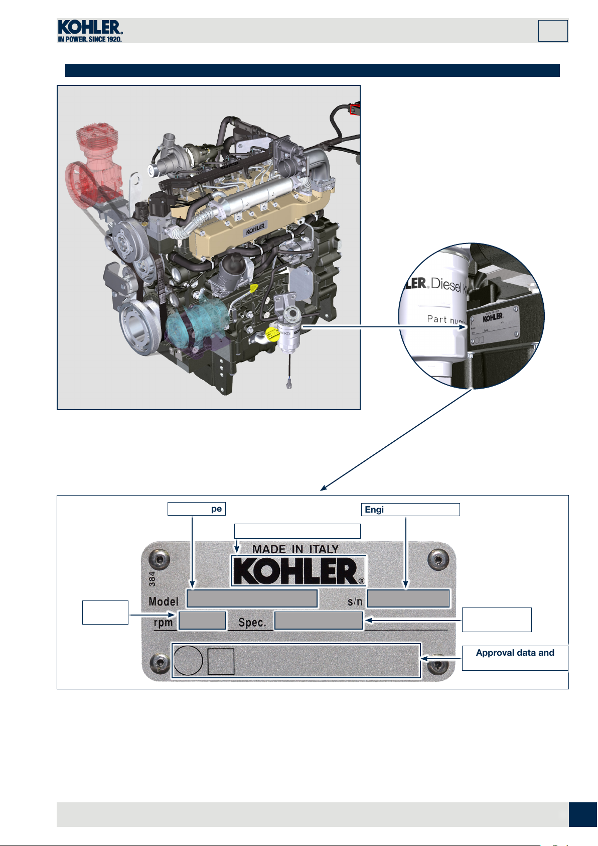
1.5 Manufacturer and motor identification data
1
Peak
rpm
Engine type
Engine serial number
Manufacturer identification
Engine
version
Approval data and
"EC" directives
ED0053032140
_02
5
EN
Page 6
1
Index
GENERAL INFORMATION
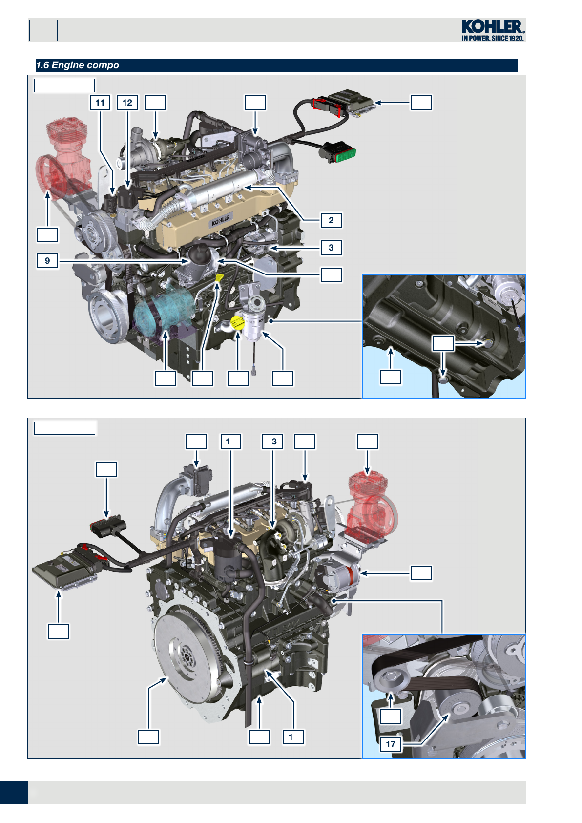
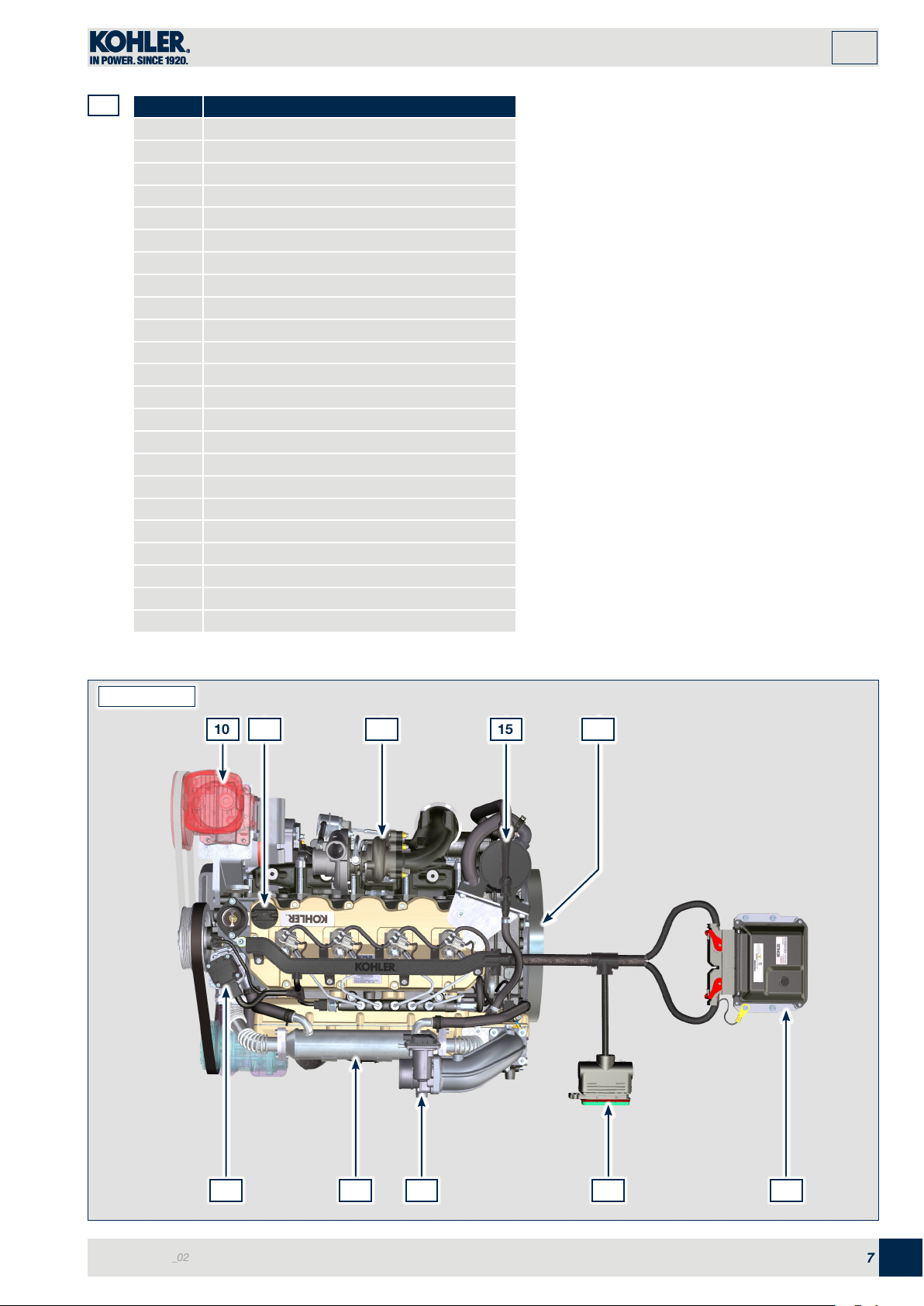
1.6 Engine component identification
SIDE VIEW A
10
11 12 13 14
2
3
9
4
678 5
19
1
21
SIDE VIEW B
1
15 13 12 1014
22
16
EN
16
20
6
1819
17
ED0053032140
_02
Page 7
GENERAL INFORMATION
Index
1
1.1
POS. DESCRIPTION
1 ECU
2 EGR Cooler
3 High-pressure fuel injection pump
4 Oil cooler
5 Fuel filter
6 Oil filler side cap
7 Oil dipstick
8 AC compressor
9 Lub. oil filter
10 Brake compressor
11 Thermostatic valve
12 EGR valve
13 Turbocharger
14 Air inlet valve
15 Oil steam separator
16 Alternator
17 Coolant pump
18 Starter motor
19 Oil sump
20 Flywheel
21 Oil drain plug
22 Wiring
23 Oil filler cap
Some components are for illustrative purposes only and
may var y.
NOTE: Components in Pos. 8, 10 are not
supplied by Kohler
SIDE VIEW C
10
1513
2023
ED0053032140
_02
12
142 22
1
7
EN
Page 8
1
Index
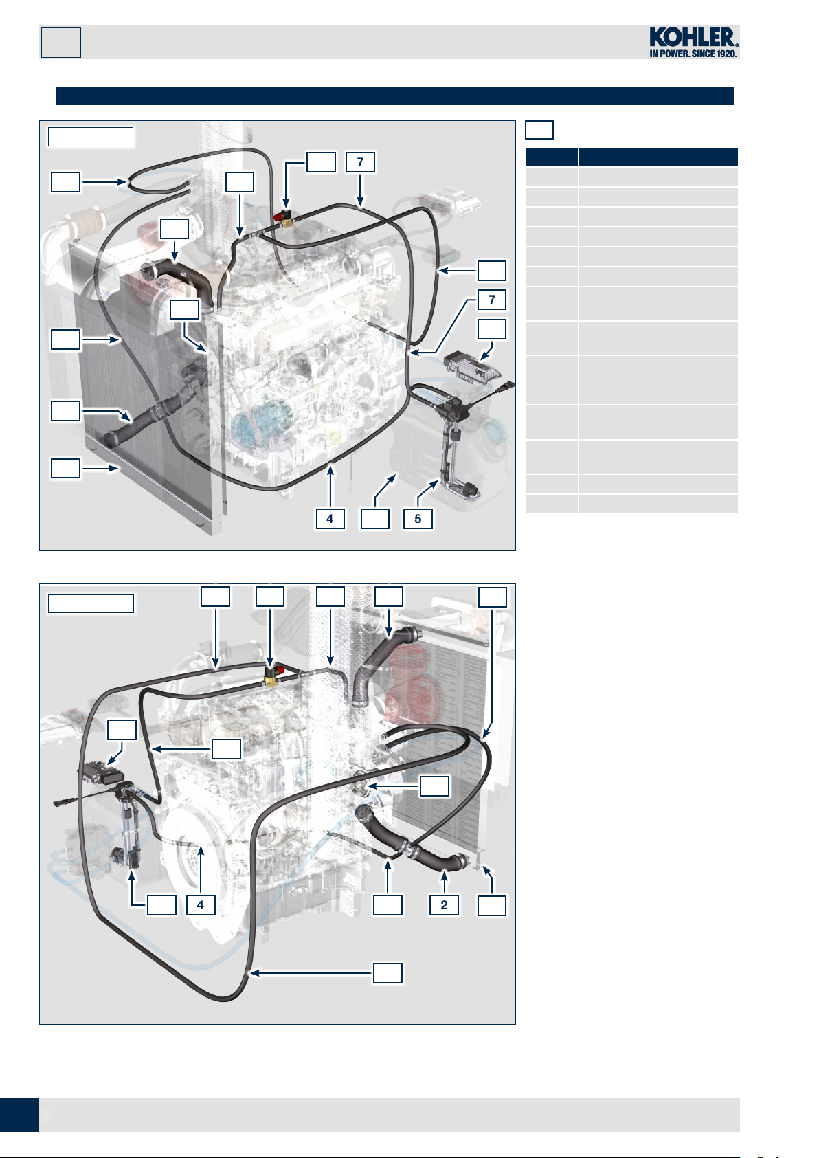
1.7 Cooling circuit
GENERAL INFORMATION
SIDE VIEW A
8
3
2
1
11
12
10
79
4 56
13
1.2
POS. DESCRIPTION
1 Radiator
2 Intake sleeve
3 Intake return tube
4 Intake return tube
5 Circuit for AdBlue heating
8
7
6 AdBlue tank
Coolant delivery tube in
7
AdBlue tank
Coolant delivery tube to
8
AdBlue injector
Electronic valve for
9
coolant delivery to AdBlue
tank
Coolant delivery tube to
10
SCR system
Coolant to radiator return
11
sleeve
12 Coolant pump
13 SCR system control unit
SIDE VIEW B
13
111098
7
12
45 4 2
8
3
1
Some components are for illustrative purposes only and may vary.
NOTE: Components in Pos. 1, 2, 3, 4, 7, 8, 10, 11 are not supplied by Kohler
8
EN
ED0053032140
_02
Page 9
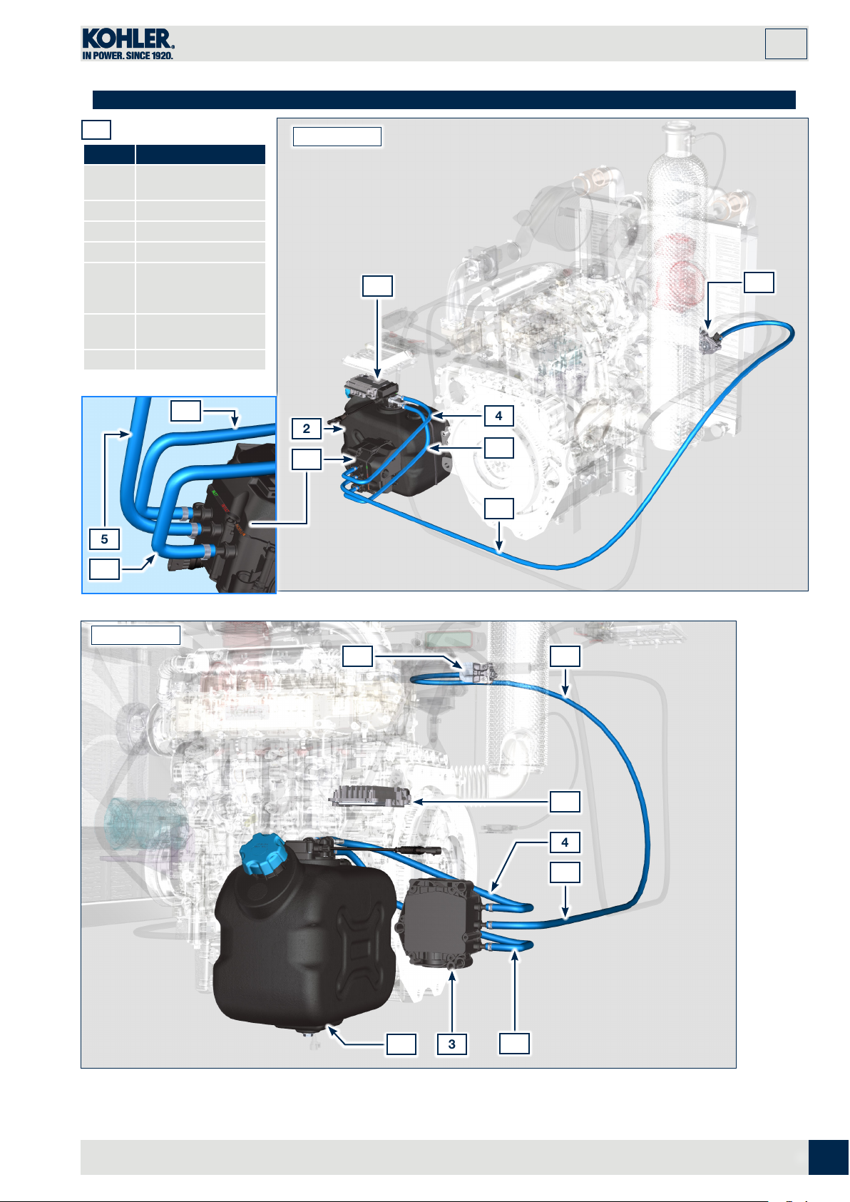
1.8 AdBlue circuit
Index
GENERAL INFORMATION
1
1.3
POS. DESCRIPTION
SCR system control
1
unit
2 AdBlue tank
3 AdBlue pump
4 AdBlue intake tube
AdBlue delivery
5
tube to AdBlue
injector
Return tube in
6
AdBlue tank
7 AdBlue injector
4
5
SIDE VIEW A
2
3
1
4
6
5
7
6
SIDE VIEW B
7 5
1
4
5
32
Some components are for illustrative purposes only and may vary.
NOTE: Components in Pos. 4, 5, 6 are not supplied by Kohler
ED0053032140
_02
6
9
EN
Page 10
1
Index
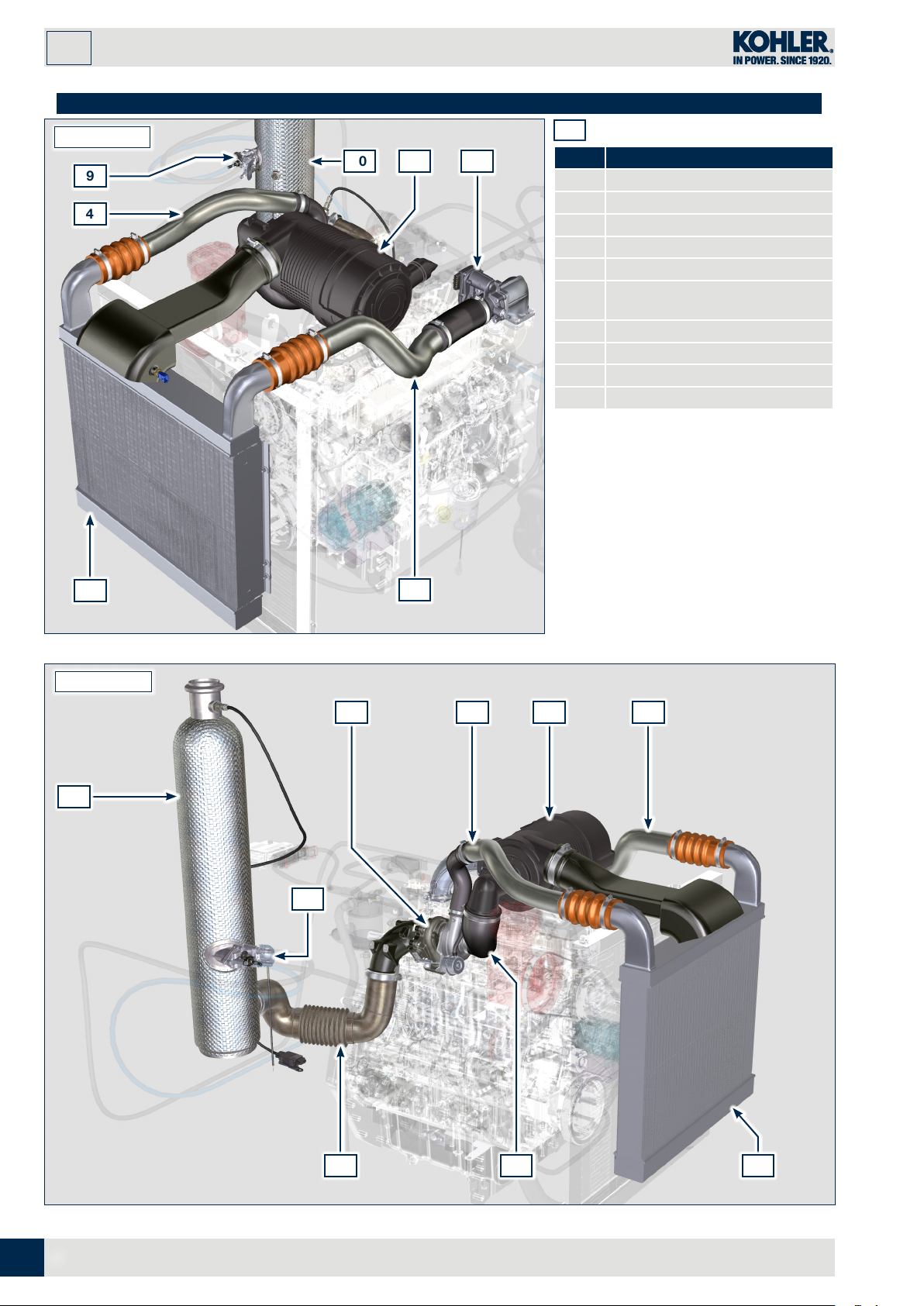
1.9 Intake and exhaust circuit
SIDE VIEW A
9
4
GENERAL INFORMATION
10 1 7
1.4
POS. DESCRIPTION
1 Air filter
2 Air intake sleeve
3 Turbocharger
4 Air delivery tube to Intercooler
5 Intercooler
Air delivery tube to intake
6
manifold
7 Air inlet valve
8 Exhaust gas delivery hose to SCR
9 AdBlue injector
10 SCR
Some components are for illustrative
purposes only and may vary.
5
SIDE VIEW B
10
NOTE: Components in Pos. 1, 2,
4, 5, 6 are not supplied by
Kohler
6
3
9
4 1 6
EN
10
8 2 5
ED0053032140
_02
Page 11
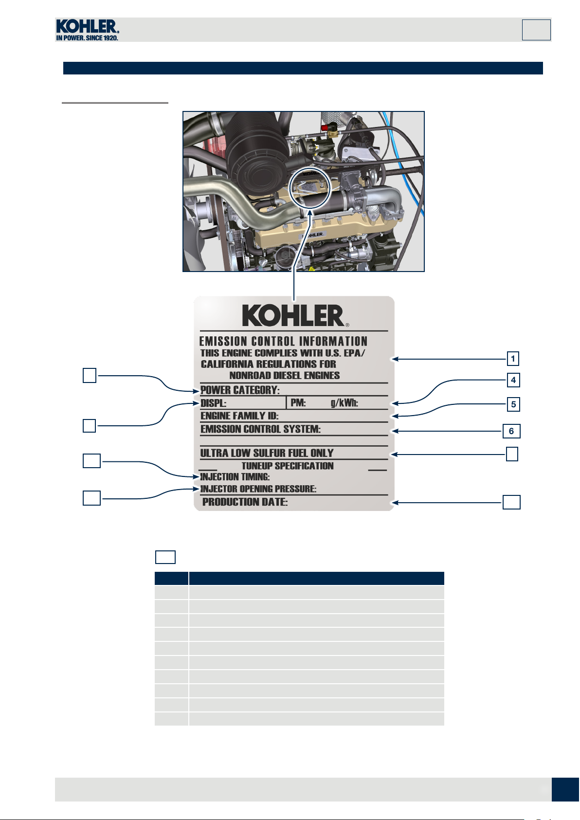
1.10 Homologation labels
Index
1.10.1 Label for EPA rules
GENERAL INFORMATION
1
1
2
3
8
9
1.5
POS. DESCRIPTION
1 Model year in compliance with the rules
2 Power category (kW)
3 Engine displacement (L)
4 Particulate emission limit (g/kWh)
5 Engine family ID
6 Emission Control System = ECS
7 Fuel with low sulphur content
8 Injection timing (*BTDC)
9 Injector opening pressure (bar)
Production date (example: 2013.JAN)
10
4
5
6
7
10
ED0053032140
_02
11
EN
Page 12
1
Index
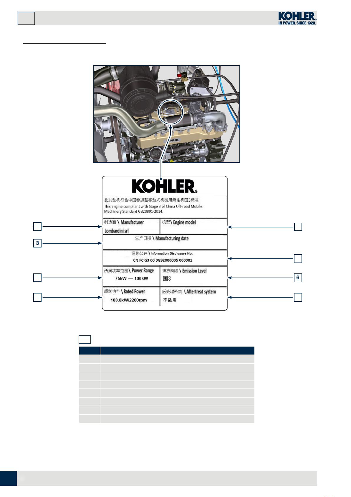
1.10.2 Label for China Standards
GENERAL INFORMATION
1
3
5
7
1.6
POS. DESCRIPTION
1 Manufacturer
2 Engine model
3 Manufactoring date
4 Certificate N°
5 Power range (kW)
6 Emission level
7 Rated power
8 Aftertreat system
2
4
6
8
EN
12
ED0053032140
_02
Page 13
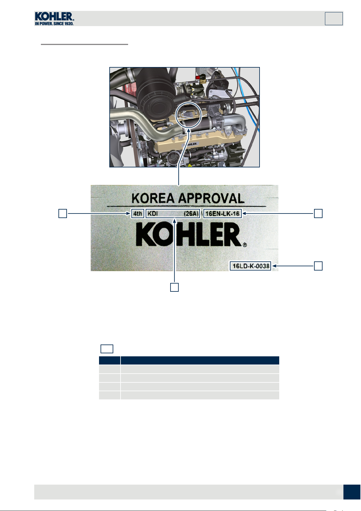
1.10.3 Label for Korea Standards
Index
GENERAL INFORMATION
1
1 4
2
1.7
POS. DESCRIPTION
1 Tier 4 Final
2 Engine model
3 Manufactoring date and manufacturer code
4 N° Korea emission certificate
3
ED0053032140
_02
13
EN
Page 14
2
Index
TECHNICAL INFORMATION
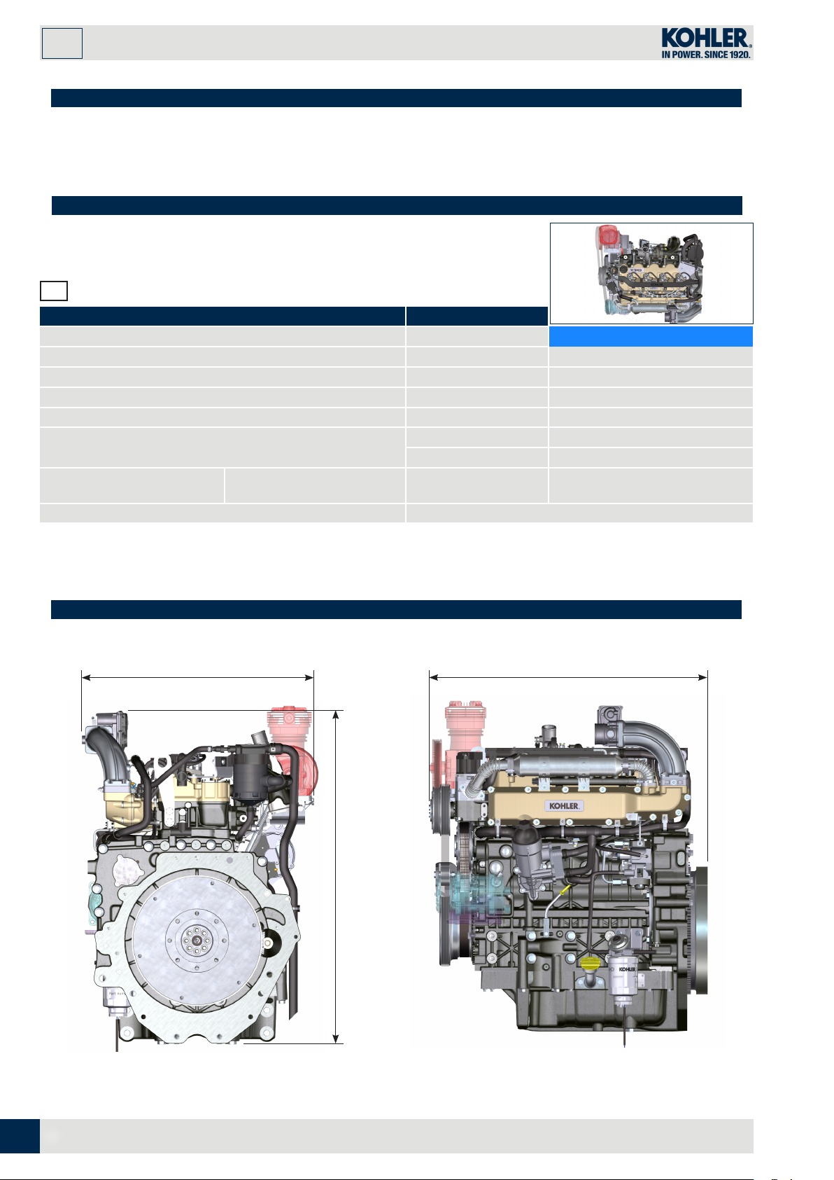
2.1 General description of the engine
- 4-stroke, in-line cylinders Diesel engine;
- Liquid-cooling system;
- 4 valves per cylinder with hydraulic tappets;
- Turbocharger with Waste-gate valve;
- Common Rail - Direct injection.
2.2 Engine specifications
2.1
TECHNICAL DATA UNIT OF MEASURE
ENGINE TYPE
CYLINDERS n. 4
BORE mm 96
STROKE mm 116
DISPLACEMENT cm
MAX INCLINATION DURING OPERATION
(even in combined)
OIL CAPACITY (MAX LEVEL.)
including oil filter
DRY WEIGHT kg 394
standard version lt. 15.6
3
a
a
KDI 340 TCR-SCR
3359
40° max. 30 minutes
45° max.1 minute
2.3 Engine dimensions (mm)
659.7
996.1
816
EN
14
ED0053032140
_02
Page 15
2.4 Oil
Index
TECHNICAL INFORMATION
2
Important
• The engine may be damaged if operated with improper oil
level.
• Do not exceed the MAX level because a sudden increase
in engine rpm could be caused by its combustion.
• Use only the recommended oil to ensure adequate
protection, efficiency and service life of the engine.
• The use of lubricants other than recommended may
shorten the engine life.
• Viscosity must be appropriate to the ambient temperature
to which the engine is to be exposed (Par. 2.4.1).
2.4.1 SAE oil classification
• In the SAE classification, oils are identified according
to viscosity without considering any other qualitative
characteristic.
2.2
VISCOSITY SAE
RECOMMENDED OIL
Danger
• Prolonged skin contact with the exhausted engine oil can
cause cancer of the skin.
• If contact with oil cannot be avoided, thoroughly wash your
hands with soap and water as soon as possible.
• For the exhausted oil disposal, refer to Par. 6.6 DISPOSAL
and SCRAPPING.
• The code is made up of two numbers. The first number
refers to the viscosity when cold, for use during winter
("W"= winter), while the second number is for viscosity at
high temperatures.
15W-40 (-15°C ÷ +50°C)
10W-30 (-25°C ÷ +40°C)
10W-40 (-25°C ÷ +50°C)
5W-30 (-30°C ÷ +40°C)
0W-40 (-40°C ÷ +50°C)
WITH
SPECIFICATIONS
• Low S.A.P.S. technology (fuel with low Sulfated Ash, Phosphorus, Sulfur content) keeps catalyst in good working conditions.
The presence of sulfated ash, phosphorus and sulfur causes with time the catalyst clogging and its consequent inefficiency.
• For Mid S.A.P.S oil sequence the sulfated ash level is the same as API CJ-4 ≤ 1.0% but as per ACEA standardization those
oils are referenced as mid SAPS.
• Filtration of oils is critical to proper operation and lubrication; always change filters regularly as specified in this manual.
API CJ-4 Low S. A . P.S
ACEA
E9 Mid S.A.P.S.
E6 Low S.A.P.S.
ED0053032140
_02
15
EN
Page 16

2
Index
2.5 Fuel
TECHNICAL INFORMATION
Important
• Use of other types of fuel could damage the engine. Do not
use dirty diesel fuel or mixtures of diesel fuel and water since
this will cause serious engine faults.
• Any failures resulting from the use of fuels other than
recommended will not be warranted.
2.3
EN 590 (biodiesel content max. 7% (V/V))
NATO F-54, equivalent to diesel fuel in accordance with EN 590
EN 590 or ASTM D 975 Grade 1, 2 -D S15 Arctic Diesel
NOTE: In a warranty case the customer must prove by a certificate from the fuel supplier that an allowed
fuel was used.
FUEL COMPATIBILITY
ASTM D 975 Grade 1-D S15
ASTM D 975 Grade 2-D S15
JIS K 2204 No. 1, No. 2
• Clean fuel prevents the fuel injectors from clogging.
Immediately clean up any spillage during refuelling.
• Never store diesel fuel in galvanized containers (i.e. coated
with zinc). Diesel fuel and the galvanized coating react
chemically to each other, producing flaking that quickly
clogs filters or causes fuel pump and/or injector failure.
Warning
KDI Electronic Injection Tier 4 final – Stage IIIB – Stage IV- Stage V certified Engines
Those engines are designed for fuels in accordance with EN 590 and ASTM D975 for a cetane number of at least 45. Since
those engines are equipped with exhaust gas after-treatment such as Diesel Oxidation Catalyst (DOC), Diesel Particulate Filter
(DPF), Selective Catalytic Reduction (SCR), they may only be operated with sulfur-free diesel fuels (EN 590, DIN 5168, ASTM
D975 Grade 2-D S15, ASTM D975 Grade 1-D S15). Otherwise, compliance with the emission requirements and durability are
not guaranteed.
Insufficient lubricating capacity can lead to serious wear problems above all in common rail injection systems. Too low a
lubricating capacity is particularly a problem in fuels with a low sulfur content (and in this respect sulfur contents <500 mg/kg
can already be considered low). An adequate lubricating capacity is guaranteed by the appropriate additives in low-sulfur (<50
mg/kg) or sulfur-free (<10 mg/kg or <15 mg/kg) diesel fuels according to EN 590 and ASTM D 975. In low-sulpur and sulfur-free
diesel fuels which do not comply with this standard, the lubricating capacity may have to be guaranteed by additives. The
parameter for sufficient lubricating capacity is a maximum wear spot of 460 micrometers in the HFRR test (EN ISO 12156-1).
EN
16
ED0053032140
_02
Page 17

TECHNICAL INFORMATION
Index
2.5.1 Fuel for low temperatures
• When operating the engine in ambient temperatures lower than 0 degrees C, use suitable low temperature fuel normally
available from fuel distributors and corresponding to the specifications of Tab. 2.3.
• These fuels reduce the formation of paraffin in diesel at low temperatures.
• When paraffin forms in the diesel, the fuel filter becomes blocked interrupting the flow of fuel.
2.5.2 Biodiesel fuel
• Fuels containing 10% methyl ester or B10, are suitable for use in this engine provided that they meet the specifications
listed in the Tab. 2.3.
• DO NOT USE vegetable oil as a biofuel for this engine.
2
2.4
Biodiesel according to EN 14214 (only permissible for mixture with diesel fuel at max. 10% (V/V))
US biodiesel according to ASTM D6751 – 09a (B100) (only permissible for mixtures with diesel fuel at 10% (V/V))
2.5.3 Synthetic fuels: GTL, CTL, BTL, HV
It is a well-known fact that engines which are operated for longer periods with conventional diesel fuel and then converted
to synthetic fuels suffer shrinkage of polymer seals in the injection system and thus fuel leaks. The reason for this behavior is
that the aromatic-free synthetic fuels can lead to a change in the selling behavior of polymer seals.
Therefore, conversion from diesel fuel to synthetic fuel may only be done after changing the critical seals. The problem of
shrinkage does not occur when an engine was operated with synthetic fuel from the start.
2.5.4 Emission-Related Installation Instructions
Failing to follow the instructions in the applications guidebook when installing a certified engine in a piece of nonroad equipment
violates federal law (40 CFR 1068.105(b)), subject to fines or other penalties as described in the Clean Air Act.
OEM must apply a separate label with the following statement: “ULTRA LOW SULFUR FUEL ONLY” near the fuel inlet.
Ensure you are installing an engine appropriately certified for your application. Constant speed engines may only be installed
on constant speed equipment for constant speed operation.
If you install the engine in a way that makes the engine's emission control information label hard to read during normal engine
maintenance, you must place a duplicate label on the equipment, as described in 40 CFR 1068.105.
BIODIESEL COMPATIBILITY
ED0053032140
_02
17
EN
Page 18

2
Index
TECHNICAL INFORMATION
2.6 AdBlue
1. Also known as "AUS 32" in Europe, "DEF" or "Urea Solution" in the USA, it is registered with the “AdBlue®” brand at the
Verband der Automobilindustrie (VDA), and must comply with the following ISO standards:
• ISO 22241-1 Quality requirements
• ISO 22241-2 Test Methods
• ISO 22241-3 Handling, transportation and Storing
• ISO 22241-4 Refilling Interface
2. The AdBlue® tank must be filled by means of the specific automatic filling nozzle at the authorised distributors, refer to the
car manual for refilling operations.
3. Upon refilling, comply with the MAX level indicated on the tank.
4. During the refilling operations prevent any impurity from entering the tank.
5. At tank inlet there is a filter that must be periodically cleaned or replaced (see maintenance and replacement table - for tank
supplied by Kohler only).
6. AdBlue® quality must comply with the specifications described in Table 2.5.
Warning
• Do not mix AdBlue® with fuel or other liquids (including water) and do not fill the fuel tank with AdBlue®.
• The presence of AdBlue® inside the specific tank is required to start the engine.
• Purchase in containers: the container, even if opened, can be stocked with the same conditions of a sealed container.
• Do not stock the container with a temperature higher than 35°C as this could alter the AdBlue®.
• In case of AdBlue® freezing inside the container (< 11°C | 51.8°F), AdBlue® can be used when it returns to its liquid state.
• Do not expose AdBlue® to direct sunlight.
• In case of opening and closing of the original purchase container, AdBlue® must be checked through a spectrometer to
check its quality before use.
• Do not insert altered AdBlue® in the tank as the engine could not respect the emission parameters, generate DCU errors
and as a consequence turn off or fail to start the engine.
2.5
PARAMETERS UNIT OF MEASUREMENT VALUE
Title Weight % 31,8 ÷ 33,2
Density at 20°C kg/m3 1.087 ÷ 1.093
Refraction index at 20°C °C 1,3814 ÷ 1,3843
Alkalinity like NH3 Weight % < 0,2
Biuret Weight % < 0,3
Aldehyde mg/kg < 5
Insoluble mg/kg < 20
Phosphates like PO4 mg/kg < 0,5
Calcium mg/kg < 0,5
Iron mg/kg < 0,5
Copper mg/kg < 0,2
Zinc mg/kg < 0,2
Chrome mg/kg < 0,2
Nickel mg/kg < 0,2
Aluminium mg/kg < 0,5
Magnesium mg/kg < 0,5
Sodium mg/kg < 0,5
Potassium mg/kg < 0,5
Freezing point °C 11
EN
18
ED0053032140
_02
Page 19

TECHNICAL INFORMATION
Index
2
2.6 Coolant recommendation
A mixture of 50% demineralized water and 50% low silicate ethylene glycol based coolant liquid must be used.
Use a Long Life or Extended Life Heavy Duty OAT coolant free of: silicates, phosphates, borates, nitrites and amines.
The following ethylene-glycol based engine coolant for all models within KDI engine family may be used:
OAT (Organic Acid Technology) Low Silicate: ASTM D-3306 D-6210
•
•
HOAT (Hybrid Organic Acid Technology) Low Silicate: ASTM D-3306 D-6210
The above coolants in concentrated formulation must be mixed with distilled, deionized, or demineralized water. A pre-mixed
formulation (40-60% or 50-50%) can be used directly when available.
Important
• Do not mix ethylene glycol and propylene glycol based coolants. Do not mix OAT and HOAT based coolant. OAT performance
life can be drastically reduced if contaminated with nitrite-containing coolants.
• Never use automotive-type coolants. These coolants do not contain the correct additives to protect heavy – duty diesel
engines.
OAT coolants are maintenance free up to 6 years or 6000hrs of operation , provided that the cooling system is topped up using
the same type of coolant. Do not mix different coolant types. Test the coolant condition annually with coolant test strips.
HOAT are not all maintenance free and it is recommended to have SCA (Supplemental Coolant Additives) added at the first
maintenance interval.
2.8 Battery recommendation
Battery not supplied by Kohler
2.6
AMBIENT TEMPERATURE BAT TERY T Y PE
RECOMMENDED BATTERIES
≥ - 15°C
< -15°C
120 Ah/20 h - 1000 CCA/SAE
130 Ah/20 h - 1100 CCA/SAE
ED0053032140
_02
19
EN
Page 20

2
Index
TECHNICAL INFORMATION
2.9 Inducement strategy of SCR system
The inducement is the operation aimed at reducing the engine performance due to a malfunction or tampering with the SCR
system detected by the DCU.
The inducement degree is decided by the ECU according to the error detected by the DCU.
The inducement can have the following 2 levels:
- Level 1: 25% reduction of the MAX available torque.
- Level 2: 50% reduction of the MAX available torque and 40% reduction of MAX rpm available.
Before activating the inducement (level 1 or level 2) the ECU activates a warning or a warning light on the car panel (refer to
the car documentation for the warning type).
The information on the car panel or the activation of the inducement can occur for the following reasons:
- Low AdBlue® level
- Poor AdBlue® quality
- Interruption of AdBlue® supply
- EGR valve malfunctioning
- Tampering with the monitoring systems of the SCR system.
The inducement strategy is applied according to:
- detected problem
- hours passed.
NOTE: Hours are reset after 40h if the DCU does not detect any fault, otherwise the hours are added to
those already counted. For low AdBlue® level, activation depends on the percentage of liquid inside
the AdBlue® tank, and the fault hours are not counted.
The strategy for the different faults is listed below:
Low AdBlue® level
- information activation on car panel: <10% of MAX level
- Level 1 inducement: <2.5% of MAX level
- Level 2 inducement: 0% of MAX level
Poor AdBlue® quality
- information activation on car panel: upon fault detection
- Level 1 inducement: after 10h from fault detection
- Level 2 inducement: after 20h from fault detection
Interruption of AdBlue® supply
- information activation on car panel: upon fault detection
- Level 1 inducement: after 10h from fault detection
- Level 2 inducement: after 20h from fault detection
EGR valve malfunctioning
- information activation on car panel: upon fault detection
- Level 1 inducement: after 36h from fault detection
- Level 2 inducement: after 100h from fault detection
Tampering with the monitoring systems of the SCR system
- information activation on car panel: upon fault detection
- Level 1 inducement: after 36h from fault detection
- Level 2 inducement: after 100h from fault detection
20
EN
ED0053032140
_02
Page 21

3.1 Safety information
Index
SAFETY INFORMATION
3
• The intended use of the engine is in conformity with the
machine on which it is mounted.
• Any use of the machine other than that described cannot
be considered as complying with its intended purpose as
specified by KOHLER .
• KOHLER declines all responsibility for any change to the
engine not described in this manual made by unauthorized
KOHLER personnel.
• A proper use of the engine, a strict observance of the
rules listed below and the rigorous application of all these
precautions will avoid the risk of accidents or injuries.
3.2 General remarks
3.2.1 Note for OEM
• When installing the KDI engines, always bear in mind that
any variation to the functional systems may result in serious
failures to the engine.
• Any improvement must be verified at KOHLER testing
laboratories before application of the engine.
• In case the app roval to a modification is not gra nted, KOHLER
shall not be deemed responsible for any consequential
failures or damages to the engine.
3.2.2 Note for end user
• Those who carry out the use and maintenance on the
engine must wear the safety equipment and the accidentprevention guards.
• KOHLER declines all direct and indirect liability for failure
to comply with the standards of conduct contained in this
manual.
• KOHLER cannot consider every reasonably unforeseeable
misuse that may cause a potential danger.
• The engine may only be assembled on a machine by
personnel specifically trained by KOHLER and who work in
compliance with the existing documentation.
• The engine has been built to the specifications of a machine
manufacturer, and it is his responsibility to ensure that all
necessary action is taken to meet the essential and legally
prescribed health and safety requirements. Any use of the
machine other than that described cannot be considered
as complying with its intended purpose as specified by
KOHLER, which therefore declines all responsibility for
accidents caused by such operations.
• The following indications are dedicated to the user of the
machine in order to reduce or eliminate risks concerning
engine operation and the relative routine maintenance work.
• The user must read these instructions carefully. Failure to do
this could lead to serious danger for his personal safety and
health and that of any persons who may be in the vicinity of
the machine.
• On starting, make sure that the engine is as horizontal as
possible, unless the machine specifications differ.
• Make sure that the machine is stable to prevent the risk of
overturning.
• The engine must not operate in places containing
inflammable materials, in explosive atmospheres, where
there is dust that can easily catch fire unless specific,
adequate and clearly indicated precautions have been
taken and have been certified for the machine.
• To prevent fire hazards, always keep the machine at least
one meter from buildings or from other machinery.
• Children and animals must be kept at a due distance from
operating machines in order to prevent hazards deriving
from their operation.
• Thoroughly wash and clean all the external parts of the
engine before performing any operation, in order to avoid
the accidental introduction of impurities/foreign bodies.
Use only water and/or appropriate products to clean the
engine. If cleaning engine with a pressure washer or steam
cleaner, it is important to maintain a minimum distance of at
least 200 mm bet ween the su rfa ce to be washe d and the noz zle.
Avoid directing the nozzle on electrical components,
cable connections and sealed rings (oil seals etc).
Thoroughly wash and clean the area surrounding the
engine following the instructions provided by machine
manufacturer.
• Fuel and oil are inflammable. The tank must only be filled
when the engine is off. Before starting, dry any spilt fuel.
• Make sure that no soundproofing panels and the ground or
floor on which the machine is standing have not soaked up
any fuel.
• Fuel vapour is highly toxic. Only refuel outdoors or in a well
ventilated place.
• Do not smoke or use open flames when refuelling.
• During operation, the surface of the engine can become
dangerously hot. Avoid touching the exhaust system in
particular.
• Before proceeding with any operation on the engine, stop it
and allow it to cool.
• Always open the radiator plug or expansion chamber with
the utmost caution, wearing protective garments and
goggles.
• The coolant fluid is under pressure. Never carry out any
inspections until the engine has cooled.
• If there is an electric fan, do not approach the engine when
it is still hot as the fan could also start operating when the
engine is at a standstill.
ED0053032140
_02
21
EN
Page 22

3
Index
Important
• The oil must be drained whilst the engine is hot. Particular
care is required to prevent burns. Do not allow oil to come
into contact with the skin because of the health hazards
involved. It is recommended to use an oil intake pump.
• During operations that involve access to moving parts of
the engine and/or removal of rotating guards, disconnect
and insulate the negative wire (-) of the battery to prevent
accidental short-circuits and to stop the starter motor from
being energized.
• Check belt tension only when the engine is off.
• Fully tighten the tank cap each time after refuelling. Do not
fill the tank right to the top but leave an adequate space for
the fuel to expand.
• To start the engine follow the specific instructions provided
in the engine and/or machine operating manual. Do not
use auxiliary starting devices not originally installed on the
machine (e.g. Startpilot).
• Before starting, remove any tools that were used to service
the engine and/or machine. Make sure that all guards have
been refitted.
• Do not mix fuel with elements such as oil or kerosene.
Failure to comply with this prohibition will cause the nonoperation of the catalyst and non-observance of the
emissions declared by KOHLER.
• Pay attention to the temperature of the oil filter when the
filter itself is replaced.
SAFETY INFORMATION
• Only check, top up and change the coolant fluid when
the engine is off and reached the ambient temperature.
Coolant fluid is polluting, it must therefore be disposed of
in the correct way.
• Do not use air and water jets at high pressures on cables,
connectors and injectors.
Important
• Only use the eyebolts A installed by KOHLER to move the
engine (Fig. 3.1).
• The angle between each lifting chain and the eyebolts shall
not exceed 15° inwards.
• The correct tightening of the lifting screws is 25Nm.
• Do not interpose spacers or washers between the eyebolts
and engine head.
• Provided that the above requirements are met, if the lifting
eyebolts are subject to permanent deformation (inwards), all
subsequent lifting operations must be performed in order to
prevent them from bending in the opposite direction.
α ≤ 15°
A
α ≤ 15°
A
EN
22
3.1
ED0053032140
_15
_02
Page 23

3.3 Safety signal description
Index
SAFETY INFORMATION
3
• To ensure safe operation please read the following
statements and understand their meaning.
• Also refer to your equipment manufacturer's manual for
other important safety information.
3.3.1 Adhesive safety plates
The following is a list of the adhesive safety plates that may be
found on the engine, which indicate potential points of danger
to the operator (Par. 3.6).
Read the Operation and Maintenance handbook before
performing any operation on the engine.
Hot Parts.
Danger of burns.
Presence of rotating parts.
Danger of jamming or cutting.
• This manual contains safety precautions which are
explained below.
• Please read them carefully.
3.3.2 Safety guards
Hereunder is a list of safety guards that must be worn prior
to carrying out any type of operation and to avoid potential
harm to the operator.
Use protective gl oves before carryin g out the operation.
Use protective glasses before carrying out the
operation.
Use sound absorbing protections before carrying out
the operation.
Presence of explosive fuel.
Danger of re or explosion.
Presence of steam and pressurized coolant.
Danger of burns.
Lifting point.
Electrical shock.
Danger of severe scalding or death.
High pressure uid.
Danger of uid penetration.
Lethal Exhaust Gases.
Danger of poisoning or death.
3.3.3 Warnings
Hereunder is a list of safety warnings that may be found in
the manual, which advise you to pay attention when carrying
out particular procedures that may be potentially dangerous
to the operator or things.
Danger
• This indicates situations of grave danger which, if ignored,
may seriously threaten the health and safety of individuals.
Important
• This indicates particularly important technical information
that should not be ignored.
ED0053032140
_02
Warning
• This indicates that failure to comply with it can cause minor
damage or injury.
23
EN
Page 24

3
Index
3.4 Information and safety signals
SAFETY INFORMATION
ACCIDE NTAL STA RT
Accidental Starts can cause
Before working on the engine or equipment, disconnect the
battery negative (-) wire.
Engine components can get extremely hot from operation.
Do not touch engine while operating or just after stopping.
Never operate the engine with heat shields or guards
removed.
Stay away while engine is in operation. Keep hands, feet,
hair, and clothing away from all moving parts to prevent
injury.
Never operate the engine with covers, shrouds, or guards
removed.
LETHAL EXHAUST GASES
Avoid inhaling exhaust fumes and never run the engine in a
closed building or confined area.
Carbon monoxide is toxic, odorless, colorless, and can
cause death if inhaled.
Do not touch wires while engine is running.
severe injury or death.
HOT PARTS
Hot Parts can cause severe
burns.
ROTATING PARTS
Rotating Parts can cause
severe injury.
Carbon Monoxide can cause
severe nausea, fainting or
death.
ELECTRICAL SHOCK
Electrical Shock can cause
injury.
HIGH PRESSURE FLUID
RISK OF PUNCTURE
High Pressure Fluids can
puncture skin and cause
severe injury or death.
Do not work on fuel system without proper training or safety
equipment.
Fluid puncture injuries are highly toxic and hazardous.
If an injury occurs, seek immediate medical attention.
EXPLOSIVE FUEL
Explosive fuel can cause fires
and severe burns.
Fuel is flammable and its vapours can ignite.
Store fuel only in approved containers, in well ventilated,
unoccupied buildings.
Do not fill the fuel tank while the engine is hot or running,
since spilled fuel could ignite if it comes in contact with hot
parts or sparks from ignition.
Do not start the engine near spilled fuel.
Never use fuel as a cleaning agent.
EXPLOSIVE GAS
Explosive Gas can cause
fires and severe acid burns.
Charge battery only in a well ventilated area.
Keep sparks, open flames, and other sources of ignition
away from the battery at all times.
Batteries produce explosive hydrogen gas while being
charged.
Keep batteries out of the reach of children.
Remove all jewelry when servicing batteries. Before
disconnecting the negative (-) ground cable, make sure all
switches are OFF.
If ON, a spark will occur at the ground cable terminal which
could cause an explosion.
CALIFORNIA
PROPOSITION 65 WARNING
Diesel engine exhaust and some of its constituents are
known to the State of California to cause cancer, birth
defects, and other reproductive harm.
3.5 Safety and environmental impact
Every organisation has a duty to implement procedures to
identify, assess and monitor the inuence of its own activities
(products, services, etc.) on the environment.
Procedures for identifying the extent of the impact on the
environment must consider the following factors:
- Liquid waste.
- Waste management.
- Soil contamination.
- Atmospheric emission.
- Use of raw materials and natural resources.
- Regulations and directives regarding environmental impac t.
24
EN
In order to minimise the impact on the environment, KOHLER
now provides a number of indications to be followed by
all persons handling the engine, for any reason, during its
expected lifetime.
- All compo nents and fluids must b e disposed of in acc ordance
with the laws of the country in which disposal is taking place.
- Keep the fuel and engine control systems and the exhaust
pipes in efficient working order to limit environmental and
noise pollution.
- When discontinuing use of the engine, select all compone nts
according to their chemical characteristics and dispose of
them separately.
ED0053032140
_15
_02
Page 25

3.6 Location of safety labels on engine
Index
SAFETY INFORMATION
3
ED0053032140
_02
25
EN
Page 26

4
Index
INFORMATION ABOUT USE
4.1 Pre-start check
Important
• Read carefully the following pages and carry out the operations described below in accordance with the instructions specified.
• Non compliance with the operations described in the following pages involves the risk of damages to the engine and vehicle
on which it is installed as well as personal and/or property damage.
• Increase the frequency of maintenance operations in heavy working conditions (engine starts but stops, very dusty and hot
environments, etc...).
• Check that the minimum required AdBlue® quantity is present inside the AdBlue® tank. Refer also to the car documentation to
check the AdBlue® level required for engine correct operation.
4.2 Running-in period
NOTE: For the first 50 hours of engine operation, it is advisable not to exceed 75% of the maximum power
supplied.
4.3 Starting and turning off
4.3.1 Starting
1. Check the level of the engine oil, fuel, coolant and AdBlue®, fill if necessary (Par. 4.5 and Par. 4.6).
2. Put the ignition key in the ignition switch (if supplied).
3. Tu n the key to ON position.
4. Tu rn the key beyond the ON position and release it when the engine starts (the key will return into ON position automatically).
Important
• Do not actuate the starter for more than 15 seconds at a time. If the engine does not start, wait for one minute before repeating
attempt.
• If engine does not start after two attempts see Tab. 7.1 and Tab. 7.2, to locate the cause.
4.3.2 After starting
Warning
• Make sure that all the warning lights on the control panel are off when the engine is running.
• Run at minimum speed for a few minutes according to table (except constant speed engine).
NOTE: To avoid damaging the engine do not use it mostly at idle for a long time.
4.7
AMBIENT TEMPERATURE TIME
≤ -20°C 2 minutes
from -20° C to -10°C 1 minutes
from -10° C to -5° C 30 seconds
from -5° C to 5° C 20 seconds
≥ 5° C 15 seconds
4.3.3 Turning off
1. Do not turn off the engine when it is running at the maximum rotation speed (except constant speed engine).
2. Before turning it off, keep it idle at minimum speed for about 1 minute.
3. Tu rn the key to OFF position.
26
EN
ED0053032140
_02
Page 27

INFORMATION ABOUT USE
Index
4
4.4 Refuelling
Important
• Before proceeding with operation, read Par. 3.2.2.
Danger
• Fill the engine off.
• The only approved fuels are those listed in Tab. 2 .3.
• In those countries where diesel has a high sulphur content, its is advisable to lubricate the engine with a high alkaline oil or
alternatively to replace the lubricating oil recommended by KOHLER more frequently.
• To avoid explosions or fire outbreaks, do not smoke or use open flames during the operations.
• Fuel vapours are highly toxic.Only carry out the operations outdoors or in a well ventilated place.
• Keep your face well away from the fuel fill to prevent harmful vapours from being inhaled.
• Dispose of fuel in the correct way and do not litter as it is highly polluting.
• When refuelling, it is advisable to use a funnel to prevent fuel from spilling out.The fuel should also be filtered to prevent dust
or dirt from entering the tank.
• Do not overfill the fuel tank. Leave room for the fuel to expand.
NOTE: At the first fuelling or if the tank was empty filling the fuel system (Par. 6.3 point 8).
4.5 Oil filling
Important
• For safety precautions see Par. 2 .4.
• Before proceeding with operation, read Par. 3.2.2.
1. Loosen the oil filler cap A.
2. Add the type oil recommended (Tab. 2.1 and Tab. 2 . 2).
3. Before checking oil engine needs to be level.
4. Remove the oil dipstick B and check that the level is up to
but does not exceed the
MAX
.
A
4.1
B
5. If level is not at the MAX. level, add additional oil.
6. Re-tighten the cap A.
Important
• Do not use the engine with the oil level below the minimum.
ED0053032140
_02
4.2
MAX
MIN
B
27
EN
Page 28

4
Index
4.6 Coolant filling
INFORMATION ABOUT USE
Important
• Before proceeding with operation, read Par. 3.2.2.
NOTE: Refer to the technical documentation
of the vehicle.
Warning
• An anti-freeze protection liquid (ANTIFREEZE) - mixed with
decalcified water - must be used.
• The freezing point of the refrigerant mixture depends on
the amount concentration in water.
• As well as lowering the freezing point, the antifreeze also
raises the boiling point.
• A 50% mixture is recommended to ensure a general level
at protection prevents the formation of rust, galvanic
currents and calcium deposits (Par. 2 .7).
4.7 AdBlue® filling
NOTE: Refer to the technical documentation of the vehicle.
EN
28
ED0053032140
_02
Page 29

INFORMATION ABOUT MAINTENANCE
Index
5
5.1 Useful information about maintenance
• This chapter shows all operations described in the Tab.
5.1 and Tab. 5.2 if you have the skills appropriate may be
directly carried out by the user.
• Periodic inspection and maintenance operations must
• Before proceeding with operation, read Par. 3.2.2.
Important
be carried out as indicated in this manual and are the
responsability of the user.
• Failure to comply with these service and maintenance
intervals increases the risk of technical damage to the
engine. Any non compliance makes the warranty become
null and void.
• In order to prevent personal and property damage read
carefully the instructions listed below before proceeding
with any operation of the engine.
Warning
• Inspections must be made when the engine is off and cold.
• Place engine on level surface to ensure accurate
measurement of oil level.
• Before starting, to avoid spillages of oil make sure that:
- the oil dipstick is inserted correctly;
- also check that:
oil drain plug and; oil filler cap are tightened firmly.
5.2 Periodic maintenance
The intervals of preventive maintenance in Tab. 5.1 and Tab. 5.2 refer to the engine operating under normal operating conditions
with fuel and oil meeting the recommended specifications.
5.1
OPERATION DESCRIPTION
Engine oil level
Coolant level
Cartridge dry-type air filter
(8)
(8) (9)
(2)
Radiator heat-exchange surface and Intercooler
Alternator belt
(8)
Rubber hose (intake air / coolant)
Fuel hose
Starter Motor
Alternator
(6)
(6)
5.2
OPERATION DESCRIPTION
Engine oil
Oil filter cartridge
(1)
(1)
Fuel filter and pre-filter cartridge
®
AdBlue
filter cartridge
Coolant hoses
Fuel line hose
(6) (7)
(6) (7)
(1) (6)
Intake manifold hose (air filter - intake manifold)
Alternator belt
Coolant
Cartridge dry-type air filter
Poly-V belt heavy environmental condition
Poly-V belt standard condition
(6)
OAT
(6) (10)
HOAT
(2)
CLEANING AND CHECKING
PERIOD (HOURS)
100 250 500 5000
PAR.
5.3
(2) (8)
Components not necessarily supplied by
KOHLER.
Refer to the technical documentation of the
vehicle
5.7
5.4
5.5
5.8
5.6
5.6
--
--
REPLACEMENT
PERIOD (HOURS)
500 1500 5000 6000
PAR.
6.1
6.2
(1)
6.3
6.5
--
--
(6) (7)
(6)
(6)
--
--
Components not necessarily supplied by
KOHLER.
Refer to the technical documentation of the
6.4
vehicle
ED0053032140
_02
29
EN
Page 30

5
Index
INFORMATION ABOUT MAINTENANCE
1. In case of low use: 12 months.
2. The period of time that must elapse before checking
the filter element depends on the environment in which
the engine operates. The air filter must be cleaned and
replaced more frequently under very dusty conditions.
6. Contact authorized KOHLER workshops.
5.3 Oil level check
1. Loosen the oil filler cap A.
Remove the oil dipstick B and check that the level is up
to MAX.
2. Pour in recommended oil until reaching the MAX level
mark.
3. Reinstall the oil dipstick B completely.
4. Re-tighten the cap A (Fig. 5.2).
7. The replacement interval is only an indication, it strongly
depends from environmental condition and hose status
detected during regular visual inspection.
8. The first check must be done after 10 hours.
9. Test the coolant condition annually with coolant test
strips.
10. It is recommended to have SCA (Supplemental Coolant
Additives) added at the first maintenance interval.
B
MAX
B
MIN
5.1
Important
• Do not use the engine with the oil level below the minimum.
5.2
5.4 Air filter check
NOTE: Component not supplied by KOHLER.
Refer to the technical documentation of the vehicle.
A
EN
30
ED0053032140
_02
Page 31

INFORMATION ABOUT MAINTENANCE
Index
5.5 Air filter check
NOTE: Components not necessarily supplied by
KOHLER.
1. Pull insert F to unlock cover A.
2. Rotate counter clockwise and remove cover A.
3. Clean the inside components A and D with a damp cloth.
4. Do not use compressed air, repeatedly tap the front side
E on a flat surface.
5
A
F
5.3
Important
• When the cartridge G is dirty, do not clean it but replace
cartridges B and G.
5. Fit cartridges G and B.
6. Fit cover A by performing the operations indicated in
points 2 and 1 in the reverse order.
A
5.4
B D
G
E
ED0053032140
_02
5.5
B
31
EN
Page 32

5
Index
INFORMATION ABOUT MAINTENANCE
Danger
• For safety precautions see Cap. 3.
5.5 Check of the radiator heat-exchanger surface
NOTE: Component not supplied by KOHLER.
Refer to the technical documentation of the vehicle
5.6 Rubber hoses check
The check is carried out by exerting a slight deflection or
bending along the pipe and near the hose clamps.
Components must be replaced if they have clear signs of
cracks, tears, cuts, leaks and do not retain a certain degree
of elasticity.
Important
• Before proceeding with operation, read Par. 3.2.2.
• If hoses are damaged contact an authorized KOHLER
workshop.
• For other pipes not illustrated refer to the technical
documentation of the vehicle.
1. Check that the:
- Fuel system hoses A are intact.
- Cooling circuit hoses B.
- Vent system pipes C.
B
5.6
A
B
C
B
A
A
5.7 Check coolant level
NOTE: Component not supplied by KOHLER.
Refer to the technical documentation of the vehicle.
32
EN
5.7
ED0053032140
_02
Page 33

INFORMATION ABOUT MAINTENANCE
Index
5.8 Check Poly-V alternator belt
NOTE: The poly-v belt is not adjustable.
1. Check the belt A condition, if worn out or deteriorated,
replace it.
NOTE: Make sure that the ribs of the belt A are
inserted correctly into the grooves of the
pulleys B (as shown in D1 and D2).
2. Start the engine and run it for some minutes, then turn
off it, and let it cool down at ambient temperature.
Check by the appropriate tool that at point p the tension
value is between 135 and 178 Hz.
NOTE: If the poly-v belt tension results out of
the above mentioned values contact
KOHLER authorised workshops for
replacement.
NOTE: Belts A2, A3 are not supplied by
KOHLER.
Refer to the technical documentation of
the vehicle.
5
A3
A2
A
P
5.8
D2
5.9 Check fuel filter cartridge
When turn on lights on control water filter cartridge fuel:
1. Gently loosen the wing screw A without removing it.
2. Drain the water if present.
3. Re-tighten the wing screw A as soon as the fuel begins
to flow.
5.9
5.10
D1
A
ED0053032140
_02
33
EN
Page 34

5
Index
INFORMATION ABOUT MAINTENANCE
5.10 Product preservation
Important
• If the engines are not to be used for 6 months, they must
be protected by carrying out the operations described in
Engine storage (up to 6 months) (Par. 5.11).
• If the engine is still not in use after the first 6 months, it
is necessary to carry out a further operation to extend the
protection period (more than 6 months) (Par. 5.12).
• If the engine is not to be used for an extended period, the
protective treatment procedure must be repeated within 24
months of the previous one.
5.11 Engine storage up to 6 months
Before storing the engine check that:
• The environments are not humid or exposed to bad weather.
Cover the engine with a proper protective sheet against
dampness and atmospheric contaminants.
• The place is not near electric panel.
• Avoid storing the engine in direct contact with the ground.
11. When cleaning the engine, if using a pressure washer
or steam cleaning device, avoid directing the nozzle on
electrical components, cable connections and sealed
rings (oil seals etc). If cleaning engine with a pressure
washer or steam cleaner, it is important to maintain
a minimum distance of at least 200mm between the
surface to be washed and the nozzle - avoiding absolutely
electrical components such as alternators, starter motors
and engine control units (ECU).
12. Treat non-painted parts with protective products.
13. Fill the AdBlue tank to the MAX level allowed.
If the engine protection is performed according to the
suggestions indicated no corrosion damage should occur.
5.13 Engine starting after storage
1. Remove the protective sheet.
2. Use a cloth soaked in degreasing product to remove the
protective treatment from the external parts.
3. Inject lubricating oil (no more than 2 cm3) into the intake
ducts.
5.12 Engine storage over 6 months
Follow the steps described in Par. 5.11.
1. Engine oil replacement (Par. 6.1).
2. Refuel with fuel additives for long storage.
The following additives are recommended:
DEFA Fluid Plus (Pakelo Lubricants),
Diesel Treatment (Green Star),
Top Diesel (Bardhal),
STP® Diesel Fuel Injector Treatment.
3. With expansion tank: make sure that the coolant is up to
the MAX level.
4. Without expansion tank: Top liquid up until the pipes
inside the radiator are covered by about 5 mm. Do not
overfill the radiator, but leave room for the fuel to expand.
5. Start the engine and keep it idle at minimum speed for 2
minutes.
6. Bring the engine to 3/4 of the MAX speed for 5÷10 minutes.
7. Turn off the engine.
8. Completely empty the fuel tank.
4. Refill the tank with fresh fuel.
5. Make sure that the oil and the coolant are up to the MAX
level.
6. Proceed with the disposal of the AdBlue contained in
the tank; replace the AdBlue pump filter and wash the
AdBlue tank/circuit with hot distilled water.
7. Check the AdBlue injector at an authorized KOHLER
workshop.
8. Start the engine and keep it idle at minimum speed for a
two about minutes.
9. Bring the engine to 75% of MAX rated speed for 5 to 10
minute.
10. Stop the engine while the oil is still hot
(Par. 6.1), discharge the protective oil in a suitable
container.
Warning
• Over time, lubricants and filters lose their properties, so it is
important consider whether they need replacing, also based
on the criteria described in Tab. 5.2.
9. Spray SAE 10W-40 on the exhaust and intake manifolds.
10. Seal the exhaust and intake ducts to prevent foreign
bodies from entering.
34
EN
11. Replace the filters (air, oil, fuel) with original spare parts.
12. Pour new oil (Par. 4.5) up to the MAX level.
13. Empty the cooling circuit completely and pour in the new
coolant up to the MAX level (Par. 4.6).
ED0053032140
_02
Page 35

INFORMATION ABOUT MAINTENANCE
Index
5.14 Unused machine
If the machine is not used for a certain amount of time, follow the operations below:
5.14 .1 Operations for the engine
5.3
POINT OPE R AT I ON
- The place must be dry and fresh throughout the period in which the machine is not used.
unused ma-
chine up to 2
1
2
3
months
Starting
unused machi-
ne from 2 to 9
months
Starting
unused machine over 9
months
Starting
- Consult the machine’s manual to disconnect the battery (before disconnecting the battery,
wait for minimum 5 mins after turning o the engine).
- Make sure the engine is not exposed to direct sunlight.
- Make sure the engine is not near any heat sources.
- Before starting the engine, check Par. 5.2 for maintenance operations.
- Consult the machine’s manual to connect the battery and start the engine.
- Perform the operations related to unused machine described in point 1.
- Perform the operations described in Par. 5.6.
- Start the engine at least every 4 months as per operations described in point 1:
- Avoid sudden accelerations for the rst few minutes.
Bring the engine to the working temperature by pressing the accelerator 3/4 from MAX.
Leave the engine running at minimum speed for a few minutes and turning o the engine.
- Before starting the engine, check Par. 5.2 for maintenance operations.
- Consult the machine’s manual to connect the battery and start the engine.
- Avoid sudden accelerations for the rst few minutes.
- Perform the operations related to unused machine described in point 1 and 2.
- Before starting the engine, check Par. 5.2 for maintenance operations.
- Check the quality of coolant from the relative testing strips.
- Consult the machine’s manual to connect the battery and start the engine.
- Avoid sudden accelerations for the rst few minutes.
5
5.14 . 2 Operations for the SCR system
5.4
POINT OPER ATI O N OPE R AT I ON
unused ma-
chine up to 2
1
2
3
months
Starting
unused machi-
ne from 2 to 9
months
Starting
unused machine over 9
months
Starting
- Perform the operations related to unused machine described in point 1 of Tab. 5.3
- Fill the AdBlue® tank with AdBlue® to the MAX level
- The ambient temperature must be kept between -40 and 40 °C
- Do not disconnect any electrical or hydraulic connections
- Before starting the engine, check Par. 5.2 for maintenance operations.
- Consult the machine’s manual to connect the battery and start the engine.
- Perform the operations related to unused machine described in point 2 in Tab. 5.3
- Fill the AdBlue® tank with AdBlue® to the MAX level
- The ambient temperature must be kept between -40 and 25 °C
- Do not disconnect any electrical or hydraulic connections
- Before starting the engine, check Par. 5.2 for maintenance operations.
- Consult the machine’s manual to connect the battery and start the engine.
- Perform the operations related to unused machine described in point 3 of Tab. 5.3
- Fill the AdBlue® tank with AdBlue® to the MAX level
- The ambient temperature must be kept between -40 and 25 °C
- Do not disconnect any electrical or hydraulic connections
- Before starting the vehicle, proceed as follows:
• Replace the AdBlue® in the tank (consult the machine’s manual)
• Replace the AdBlue® filter (Par. 6.5)
• Check Par. 5.2 for maintenance frequency.
• Consult the machine’s manual to connect the battery.
• Start the engine. If faults are detected when starting the engine or during operation, turn off
the engine and wait 5 mins before starting the engine.
• If the fault persists, contact KOHLER authorised workshops.
ED0053032140
_02
35
EN
Page 36

6
Index
INFORMATION ABOUT REPLACEMENTS
Danger
• Disconnect the negative wire (-) from the battery to avoid accidental engine starting.
Important
• Before proceeding with operation, read Par. 3.3.2.
6.1 Engine oil replacement
Important
• Place engine on level surface to ensure accurate
measurement of oil level.
• Before proceeding, perform the operation described in
Par. 6.2 - Point 1.
NOTE: Perform this operation with warm engine,
to get a better fluidity of the oil and get
a full discharge of oil and impurities
contained in it.
1. Loosen the oil filler cap A (Fig. 6.1).
2. Remove the oil dipstick B.
3. Remove the oil drain plug D and the gasket E
(the oil drain plug is on both sides of the oil sump).
4. Drain oil in an appropriate container (For the exhausted oil
disposal, refer to (Par. 6.6 DISPOSAL and SCRAPPING).
5. Replace gasket E.
6. Tighten the drain oil plug D (tightening torque at 50 Nm).
6.1
A
B
E
7. Perform the operation described in Par. 6. 2 - point 2 to 5.
8. Add the type oil recommended (Tab. 2.1 and Tab. 2.2).
Important
• Do not exceed the MAX level on the dipstick.
• Do not use the engine with the oil level below the MIN.
9. Fit and remove the oil dipstick B to check the level. Pour
in fluid until reaching the MAX level mark.
10. Upon completion, reinstall the oil dipstick B completely.
11. Tighten the cap A.
36
EN
6.2
6.3
D
MAX
MIN
ED0053032140
B
_02
Page 37

INFORMATION ABOUT REPLACEMENTS
Index
Warning
• Oil filter cartridge replacement (Par. 6.2) and fuel filter replacement (Par. 6.3)
• In case of low use replace it 12 months.
• For disposal of oil filter cartridge and fuel filter refer to
Par. 6.6 DISPOSAL and SCRAPPING.
6.2 Oil filter cartridge replacement
A
Important
• Electric/pneumatic screwdrivers are forbidden.
A
6
1. Unscrew cartridge holder cover A by performing three
complete turns and wait 1 minute.
NOTE: This operation allows to oil contained in
the support F to flow into the oil sump in
the correct way.
2. Unscrew cartridge holder cover A and check that the oil
in the lub. oil filter support F has flowed towards the oil
sump.
3. Remove the cap A as well as the oil cartridge B from the
oil filter support.
4. Remove and replace the oil cartridge B with a new one.
Remove and replace the gaskets C, D and E with new
ones.
5. Fit and tighten the cover A on the oil filter support F,
tightening it with a torque wrench G (tightening torque of
25 Nm).
B
F
6.4
D
C
B
E
6.5
ED0053032140
_02
6.6
A
F
37
EN
Page 38

6
Index
INFORMATION ABOUT REPLACEMENTS
6.3 Fuel filter and pre-filter cartridge replacement
NOTE: The fuel filter is situated on the
crankcase of the engine or it may be
assembled on the frame of the vehicle.
1. Disconnect the cable A of the water presence sensor C.
2. Remove the water presence sensor C from its cartridge B.
3. Loosen the cartridge B using the appropriate wrench.
4. Lubricate the gasket D of the new cartridge B.
Important
• Do not fill the new cartridge B with fuel.
5. Tighten the new empty cartridge B (Fig. 6.8) on the diesel
fuel filter support E using the special wrench (tightening
torque of 17 Nm).
6. Tighten the water presence sensor C on the new cartridge
B (tightening torque of 5 Nm).
7. Reconnect the cable A of the water presence sensor C.
B
6.7
G
A
C
B
E
B
D
NOTE: Bleeding.
8. Push repeatedly the button G in order to fill the circuit.
6.4 Air filter cartridge replacement
NOTE: Component not necessarily supplied by
KOHLER.
1. Pull insert F to unlock cover A.
2. Rotate counter clockwise and remove cover A.
3. Remove the cartridges B and G.
4. Fit cartridges G and B.
5. Fit cover A by performing the operations indicated in
points 2 and 1 in the reverse order.
6.8
6.9
B
C
A
F
A
GB D
EN
38
6.10
ED0053032140
_02
Page 39

INFORMATION ABOUT REPLACEMENTS
Index
6.5 Replacement of AdBlue® filter
6
Warning
• Do not lubricate gaskets A with oil or fuel.
• Filter D includes gaskets A in the package.
• Avoid any type of contamination during replacement.
• Before starting any operations, make sure the key on
the machine’s panel is OFF and the AdBlue® pump has
executed the circuit emptying operation.
1. Loosen cap B.
2. Remove cap B and extract filter bracket C.
3. Extract filter D.
4. Use warm AdBlue® to clean the seat of filter D on pump
E if impurities are detected.
5. Lubricate the A gaskets with AdBlue® or distilled water.
6. Place the filter bracket C together with filter D inside
pump E.
7. Tighten cap B (tightening torque of 20 Nm).
6.11
E
D
C
B
E
B
A
D
A
C
6.6 Disposal and scrapping
• In case of scrapping, the engine shall be disposed of in
appropriate locations, in conformity with the law in force.
• Before scrapping, it is necessary to separate the rubber or
plastic parts from the rest of the components.
6.12
• The parts only composed of plastic material, aluminium
and steel can be recycled if collected by the appropriate
centers.
• Waste oil must properly be recycled and disposed of in the
correct way to safeguard the environment. According to the
laws in force, it is classified as hazardous waste, therefore it
must be collected by the appropriate centers.
ED0053032140
_02
39
EN
Page 40

7
Index
INFORMATION ABOUT FAILURES
7.1 Useful information about failures
• This chapter contains information about the problems that may appear during engine operation with its causes and trouble
shooting Tab. 7.2.
• In some cases, you shall turn off the engine immediately to avoid further damage Tab. 7.1.
7.5
1 Warning RED light turn on
2 The oil pressure indicator light turns on while running
3 The engine rpms suddenly increase and decrease
4 A sudden and/or unusual noise is heard
5 Colour the exhaust fumes suddenly darkens
THE ENGINE MUST BE IMMEDIATELY TURNED OFF WHEN
7.6
TROUBLES POSSIBLE CAUSE SOLUTION PAR.
Warning YELLOW light
turn on
Engine ECU has detect a malfunctions Contact KOHLER authorised workshops
Sulphated battery terminals corroded Clean the battery terminals
Battery voltage too low Recharge the battery or replace it
Low fuel level Refuel 4.4
Frozen fuel Contact KOHLER authorised workshops
The engine does not
start
Clogged fuel filter Replace with a new filter 6.3
Air suction in fuel system Contact KOHLER authorised workshops
Clogged air filter Replace with a new filter 6.4
Clogged pipes Contact KOHLER authorised workshops
Open fuse Replace with a new fuse
Intake or exhaust system clogged Contact KOHLER authorised workshops
Inefficient electrical connections Clean the electrical contacts
Sulphated battery terminals Clean the battery terminals
Engine starts but stops
Clogged fuel filter
Replace with a new filter and clean the
tank
Clogged fuel pipes Contact KOHLER authorised workshops
Safety protocol in starting Wait some seconds
Engine doesn't rev up
RPM instability at idle
speed
Low
idle speed
Blue smoke
Excessive fuel
consumption
Throttle to MAX in starting
Clogged fuel pipes Contact KOHLER authorised workshops
Clogged fuel pipes Contact KOHLER authorised workshops
Poor quality fuel Clean the tank and refuel with quality fuel 2.5
High oil sump level Replace the engine oil
Clogged air filter Replace with a new filter 6.4
Clogged air filter Replace with a new filter
High oil sump level Replace the engine oil
Release the throttle and wait some
seconds
Clogged air filter Replace with a new filter
Engine lost its initial
performance
Clogged fuel pipes Contact KOHLER authorised workshops
Cheap fuel Clean the tank and refuel with quality fuel
High oil sump level Replace the engine oil
Slow acceleration Clogged fuel filter Replace the fuel filter 6.3
Engine jerking Clogged fuel pipes Contact KOHLER authorised workshops
Insufficient coolant level Fill up to the level
Engine overheats
High oil sump level Replace the engine oil
Clogged radiator Clean the radiator
--
--
--
--
--
--
--
--
--
--
--
--
--
--
--
--
6.4
--
6.3
--
--
--
--
4.6
--
--
- In the event that the solutions proposed in Tab. 7.2 do not eliminate the trouble, contact a KOHLER authorized workshop.
EN
40
ED0053032140
_02
Page 41

INFORMATION ABOUT WARRANTY
Index
8
KOHLER DIESEL ENGINES GLOBAL WARRANTY TERMS
1. WARRANTY PERIOD
Kohler Co. warrants to the End User that each Diesel engine will be free from manufacturing defects in materials or workmanship
in normal service for the applicable coverage period or operating hours (whichever comes first) set forth below, provided the
engine is operated and maintained in accordance with Kohler Co.’s instructions and manuals.
ENGINE SERIES WARRANTY PERIOD OPERATING HOURS WARRANTY COVERAGE
KOHLER Diesel (non KDI) 3 Years 0 – 2.000 100% Parts & Labor
0 – 2.000 100% Parts & Labor
KOHLER KDI 3 Years
2.001 – 6.000 Major Components Only*
Lombardini Diesel 2 Years 0 – 2.000 100% Parts & Labor
*Major component defects are failures related to crankcase casting, cylinder head casting, crankshaft, crankshaft pulley,
camshaft, connecting rod, flywheel, oil pump.
For the Warranty Period stated above, the period begins on the date of purchase of the finished equipment on which the engine
is installed. If no hour meter is installed on the application, the Operating Hours will be calculated as 4 hours of use per day
for 5 days per week beginning on the date of purchase.
Kohler Co.’s obligation under this warranty is expressly limited, at its option, to an appropriate adjustment, repair or replacement
of such part or parts as found to be defective following an inspection by Kohler Co. or an authorized service facility designated
by Kohler Co.
SPARE PARTS WARRANTY PERIOD OPERATING HOURS WARRANTY COVERAGE
KOHLER and Lombardini
Diesel Parts
Parts/components that are schedule d to be replaced as par t of the required maintenance schedule will be covered under Kohler
Co.’s warranty from date of purchase of the part up to the first scheduled replacement point for the subject parts/ components.
All other Spare Parts items are covered by the above warranty provided that the repairs have been executed by Kohler Co or
by an Authorized Kohler Service Dealer.
2. EXCLUSIONS
The following items are not covered by this warranty.
• Damage caused by: (i) an accident or casualty; (ii) unreasonable use or neglect; (iii) normal wear; (iv) premature wear from
improper maintenance; (v) improper storage; (vi) old or contaminated fuel left within the fuel system, which includes but is not
limited to tanks, fuel lines, or fuel injection components; (vii) unapproved modifications.
• Failures caused by: (i) faulty repairs made by any party other than Kohler Co. or an authorized service facility designated by
Kohler Co.; (ii) use of non-Kohler replacement service parts; or (iii) additional damages caused by a lack of prescribed actions
as a result of an alarm light activation, either caused by fault or negligence or un-attended use of the engine; (iv) an act
beyond the control of Kohler Co., which includes but is not limited to theft, vandalism, fire, lightning, earthquake, windstorm,
hail, volcanic eruption, flood or tornado.
• Transportation charges or travel expenses in connection with the repair or replacement of defective parts on the engine.
• Engine accessories such as fuel tanks, clutches, transmissions, power drive assemblies, and batteries, unless supplied or
installed by Kohler Co.
• Engines installed in an application not formally reviewed by Kohler.
• Rental of other equipment during performance of warranty repairs All items subject to wear and to periodical maintenance
such as listed in the Use & Maintenance Manual (such as air, oil or fuel filters, belts etc.) are warranted for a period equal to
the prescribed interval of replacement as listed in the Manual.
• Fuel, lubricating oil, coolant/antifreeze.
2 Years 0 – 2.000 100% Parts & Labor
ED0053032140
_02
41
EN
Page 42

8
Index
IMPLIED OR STATUTORY WARRANTIES, INCLUDING THOSE OF MERCHANTABILITY AND FITNESS FOR A PARTICULAR
PURPOSE, ARE EXPRESSLY LIMITED TO THE DURATION OF THIS WRITTEN WARRANTY. KOHLER CO. MAKES NO OTHER
EXPRESS WARRANTY, NOR IS ANYONE AUTHORIZED TO MAKE ANY ON KOHLER CO.’S BEHALF. KOHLER CO. AND/OR
THE SELLER SHALL NOT BE LIABLE FOR SPECIAL, INDIRECT, INCIDENTAL, OR CONSEQUENTIAL DAMAGES OF ANY KIND.
3. TO OBTAIN WARRANTY SERVICE
The repair shall be executed by a KOHLER Authorized Service Dealer designated by Kohler.
USA & CANADA:
List of Authorized dealers can be found by visiting www.kohlerengines.com or telephone 1-800-544-2444 (U.S.A. and Canada)
ENGINE DIVISION, Kohler Co., Kohler Wisconsin
EUROPE, MIDDLE EAST, AND ASIA
List of Authorized dealers can be found by visiting dealers.kohlerpower.it.
CENTRAL AND SOUTH AMERICA:
List of Authorized dealers can be found by visiting dealers.kohlerpower.it.
CHINA AND ASIA PACIFIC
List of Authorized dealers can be found by visiting dealers.kohlerpower.it.
INDIA
List of Authorized dealers can be found by visiting dealers.kohlerpower.it.
Note: Specific Warranty Terms and conditions do apply to engines directly sold in India.
INFORMATION ABOUT WARRANTY
4. OWNER'S WARRANTY RESPONSIBILITIES
1. As the off-road engine owner, you are responsible for the performance of the required maintenance listed in your Use &
Maintenance Manual. Kohler Co. recommends that you retain all receipts covering maintenance on your off-road & marine
engine, but Kohler Co. cannot deny warranty solely for the lack of receipts or for your failure to ensure the performance of
all scheduled maintenance.
2. As the off-road & marine engine owner, you should however be aware that Kohler Co. may deny you warranty coverage if
your off-road & marine engine or a part shows signs of malfunction or failed due to abuse, neglect, improper maintenance
or unapproved modifications.
3. Yo ur e ngine is designed to ope rate on diesel fuel only. Diesel fu el an all other fluids use d shall comply with the re commendation
listed in the Use & Maintenance Manual. Use of any other fuel or fluids may result in your engine breakage, premature wear
or no longer operating in compliance with the California & US EPA emissions requirements.
4. Yo u are responsible for initiating the warranty process. The ARB & US EPA suggests that you present your off-road &
Marine engine to a Kohler Co. dealer as soon as a problem exists. The warranty repairs should be completed by the dealer
as expeditiously as possible.
5. COVERAGE
Kohler Co. will repair or replace emission control system parts, components and sub-assemblies found to be defective with
respect to materials or workmanship at no cost to you including engine exhaust system related diagnosis, labor and parts,
provided that no un-authorized modification of any kind has been executed on the engine, and its parts, components and
sub-assemblies.
The choice and responsibility of the decision to repair or replace an emission control system defect will be solely that of Kohler
Co. Emission control system parts/ components covered by the Federal and California Emission Control Systems Limited
Warranty are listed below
engine is defective, the part will be repaired or replaced by Kohler Co.
Fuel injector(s) Electronic control unit (ECU) if equipped
Injection pump(s) Sensors associated with ECU operation
Exhaust manifold Emission control information labels
Intake manifold Turbocharger (if equipped)
Exhaust gas recirculation (EGR) tube Fuel limiting device
Crankcase ventilation valve
42
EN
Aftertreatment Systems if equipped and other components
when present
ED0053032140
_02
Page 43

INFORMATION ABOUT WARRANTY
Index
Parts/components that are scheduled to be replaced as part of the required maintenance schedule will be covered under
the warranty provisions for a period of time up to the first scheduled replacement point for the subject parts/ components.
Subseque nt damage to other engine co mponents as a direct re sult of a warrantable failure an exhaust e mission part / component
will be covered under the warranty provisions described herein.
6. MAINTENANCE AND REPAIR REQUIREMENTS
The owner is responsible for the proper use and maintenance of the engine. Kohler Co. recommends that all receipts and
records covering the performance of regular maintenance be retained in case questions arise. If the engine is resold during the
warranty period, the maintenance records should be transferred to each subsequent owner. Kohler Co. may not deny warranty
repairs solely because of the lack of repair, maintenance or failure to keep maintenance records.
Normal maintenance, replacement or repair of emission control devices and systems may be performed by any repair
establishment or individual; however, warranty repairs must be performed by a Kohler authorized service center.
7. CALIFORNIA AND FEDERAL EMISSION CONTROLWARRANTY STATEMENT, OFF-ROAD & MARINE DIESEL
ENGINES (USA ONLY)
The California Air Resources Board (CARB), U.S. environmental protection agency (EPA), and Kohler Co. are pleased to
explain the emission control system warranty on your [current model year – {2+ current model year}] off-road compression
ignition and marine (diesel) engine. In California (“the state”) and US EPA regulated region, new heavy-duty off-road & marine
engines must be designed, built and equipped to meet the state’s and US EPA anti-smog standards. The warranty period
shall begin on the date the engine or equipment is delivered to an ultimate purchaser. Kohler Co. must warrant the emission
control system on your engine for the periods of time listed in the section below, provided there has been no abuse, neglect
or improper maintenance of your engine.
Your emission control system may include parts such as the fuel injection system and the air-induction system. Also included
maybe hoses, belts, connectors and other emission related assemblies.
8
When a warrantable condition exists, Kohler Co. will repair your heavy-duty off-road & marine engine at no cost to you including
diagnosis, parts and labor.
The owner shall not be charged for diagnostic labor that leads to the determination that a warranted part is in fact defective,
provided that such diagnostic work is performed at a warranty station.
MANUFACTURER’S WARRANTY COVERAGE:
The [current model year – {2+ current model year}] heavy-duty off-road & marine engines are warranted for the periods listed
below. If any emission-related part on your engine is defective, the part will be repaired or replaced by Kohler Co.
VARIABLE SPEED OR
CONSTANT SPEED
Constant speed 19 ≤kW <37 3,000 rpm or higher
Constant speed 19 ≤kW <37 Less than 3,000 rpm
Variable speed 19 ≤kW <37 Any speed
Variable speed or constant
speed
MARINE DIESEL ENGINE
kW ≥37 Any speed
KW <19 ANY SPEED
1,500 HOURS OR TWO
YEARS, WHICHEVER
COMES FIRST.
1,500 hours or two years,
whichever comes first.
3,000 hours or five years,
whichever comes first.
3,000 hours or five years,
whichever comes first.
3,000 hours or five years,
whichever comes first.
ENGINE POWER WARRANTY PERIOD
kW < 19 1,500 hours or 2,5 years, whichever comes first.
19 ≤ kW < 37 2,500 hours or 3,5 years, whichever comes first.
37 ≤ kW < 75 5,000 hours or 5 years, whichever comes first.
ED0053032140
_02
43
EN
Page 44

9
Index
GLOSSARY
A Alternator:
Authorised workshop: Kohler authorised service centre.
B Bore: Internal diameter of the cylinder in combustion engines.
C Catalyst: A device in charge of filtering exhausted gas.
Combustion:
Common Rail:
D DCU:
E EC: European Community.
ECS: Emission Control System
ECU:
EGR Cooler:
EGR:
Electronic injector:
EPA:
F Fig.: Figure.
G Galvanised: Material that has undergone surface protection treatment.
H Heavy conditions:
I Intercooler:
K KDI: Kohler Direct Injection
M Maintenance - periodic:
MAX: Maximum.
Methyl ester
Min.: Minutes.
MIN: Minimum.
Model:
O Oil Cooler: Small radiator used to cool the oil.
P Par.: Paragraph.
Paraffin: Fatty and solid substance that may form inside the diesel.
Poly-V:
A component that transforms mechanical energy into AC
electrical energy.
Chemical reaction of a mixture composed of fuel and fuel (air)
inside a combustion chamber.
A high-pressure "Common Duct" that produces a constant
supply of fuel directly to the injectors.
Dosing Control Unit - It is a control unit that checks the
SCR system adjusting the AdBlue dosage inside the SCR
catalytic converter according to the parameters detected by
the different sensors.
Electronic Control Unit; an electronic device in charge of
electronically detecting and controlling other electronic control
devices.
Recirculated exhaust gas cooling; a system that is able to
cool recirculated gas (EGR) from the exhaust. This enables
the temperature to remain constant inside the intake manifold,
thus improving combustion inside the cylinders and breaking
down pollutants further.
Exhaust Gas Recirculation, in internal combustion engines; a
system that enables recirculation of combusted gas by means
of taking it in once again, which enables it to break down a
part of the pollutants present in the exhaust gas.
An electronically activated component able to inject jets of
atomised fuel inside the cylinders.
Environmenta l Protection Agency. The United State s' authori ty
that safeguards the environment; its duty is to govern and
control polluting emissions.
Type of extreme condition referred to the work environment
in which the engine is used (very dusty - dirty area, or in a
contaminated environment due to various types of gas).
Air-cooling element under pressure from the turbo situated
between the turbine and intake manifold.
A group of maintenance actions that have the sole objective to
control and r eplace elements on th eir expiry, without modif ying
or improving the functions carried out by the system, neither
increasing the value nor improving performance.
It is a mixture of products by means of a chemical conversion
of oils and animal and/or vegetable fat, which is used to
produce Biofuel.
Model, engine identification plate, which indicates the engine's
model.
Poly-V, the name associated with a service belt, which derives
from the profile of its section that is constructed with joined Vs.
EN
44
ED0053032140
_02
Page 45

GLOSSARY
Index
R Ref.: Reference.
S SCR: Selective Catalytic Reduction
s/n:
Spec.:
T Tab.: Table.
TCR: Turbo Common Rail.
Tightening torque:
Serial number (engine identification name plate) indicating the
engine identification series/chassis number.
Specification, (engine identification name plate) indicating the
engine version.
A term indicated for installation of threaded components and
which is determined by means of a unit of measurement Nm.
9
T-MAP:
Turbocharger:
U Used oil:
W Waste-Gate valve:
T-MAP (sensor), measures the temperature and absolute
pressure inside the intake collector.
Device that compresses air intake by sending it to the intake
manifold by means of a turbine.
Oil altered by operation or time, which is no longer compliant
for correct lubrication of the components.
A device, which is directly or automatically controlled, used to
limit the pressure of exhaust gas inside the turbine.
ED0053032140
_02
45
EN
Page 46

NOTES
Index
........................................................................................................................................................
........................................................................................................................................................
........................................................................................................................................................
........................................................................................................................................................
........................................................................................................................................................
........................................................................................................................................................
........................................................................................................................................................
........................................................................................................................................................
........................................................................................................................................................
........................................................................................................................................................
........................................................................................................................................................
........................................................................................................................................................
........................................................................................................................................................
........................................................................................................................................................
........................................................................................................................................................
........................................................................................................................................................
........................................................................................................................................................
........................................................................................................................................................
........................................................................................................................................................
........................................................................................................................................................
........................................................................................................................................................
........................................................................................................................................................
........................................................................................................................................................
........................................................................................................................................................
........................................................................................................................................................
........................................................................................................................................................
........................................................................................................................................................
........................................................................................................................................................
........................................................................................................................................................
........................................................................................................................................................
EN
46
ED005332140
_02
Page 47

NOTES
Index
........................................................................................................................................................
........................................................................................................................................................
........................................................................................................................................................
........................................................................................................................................................
........................................................................................................................................................
........................................................................................................................................................
........................................................................................................................................................
........................................................................................................................................................
........................................................................................................................................................
........................................................................................................................................................
........................................................................................................................................................
........................................................................................................................................................
........................................................................................................................................................
........................................................................................................................................................
........................................................................................................................................................
........................................................................................................................................................
........................................................................................................................................................
........................................................................................................................................................
........................................................................................................................................................
........................................................................................................................................................
........................................................................................................................................................
........................................................................................................................................................
........................................................................................................................................................
........................................................................................................................................................
........................................................................................................................................................
........................................................................................................................................................
........................................................................................................................................................
........................................................................................................................................................
........................................................................................................................................................
........................................................................................................................................................
ED005332140
_02
Diesel engi ne exhaust and some of its const ituents are known
to the State of California to cause cancer, birth defects, and
other reproductive harm.
PROPOSITION 65 WARNING
CALIFORNIA
47
EN
Page 48

Lombardini s.r.l. is a part of Kohler Group.
Lombardini has manufacturing facilities
in Italy, Slovakia and India and sales
subsidiaries in France, Germany, UK, Spain
and Singapore. Kohler/Lombardini reserves
the right to make modifications without prior
notice.
www.lombardini.it
DEUTSCHLAND
Lombardini Motoren GmbH
Fritz-Klatte-Str. 6, Bürogebäude 2
D – 65933 Frankfurt
Hessen, DEUTSCHLAND
T. +49-(0)69-9508160
F. +49-(0)69-950816-30
EUROPE
Lombardini Srl
Via Cav. del lavoro
A. Lombardini n° 2
42124 Reggio Emilia, ITALY
T. +39-(0)522-389-1
F. +39-(0)522-389-503
UK
Lombardini U.K. Ltd
1, Rochester Barn - Eynsham Road
OX2 9NH
Oxford, UK
T. +44-(0)1865-863858
F. +44-(0)1865-861754
USA & CANADA
Kohler Co.
444 Highland Drive,
Kohler - Wisconsin (53044), US
T. +1 920 457 4441
F. +1 920 459 1570
ESPAÑA
Lombardini ESPAÑA, S.L.
P.I. Cova Solera 1-9
08191 - Rubí (Barcelona)
ESPAÑA
T. +34-(0)9358-62111
F. +34-(0)9369-71613
FRANCE
Lombardini France S.a.s.
47 Alléè de Riottier,
69400 Limas, FRANCE
T. +33-(0)474-626500
F. +33-(0)474-623945
CHINA & ROAPAC
Kohler China INVESTMENT Co. Ltd
no.158, Jiang Chang San Road,
200436, Zhabe, Shanghai
CHINA
Tel: +86 400-0120-648
Fax: +86 21 61078904
 Loading...