

Page 1
Installation and Care Instructions
Sliding Bath and Shower Doors
1201264-2-E
Sliding Shower DoorsSliding Bath Doors
USA/Canada: 1-800-4KOHLER
México: 001-800-456-4537
WARNING: Risk of serious injury. Damage prior to
installation can result in glass shattering. Inspect the
glass and all parts for damage before installation.
WARNING: Risk of serious injury. Improper
installation can result in glass shattering. Follow all
installation instructions.
WARNING: Risk of serious injury. Do not cut tempered
glass. Tempered glass will shatter if cut.
WARNING: Risk of serious injury. Shower door and
side panels can shatter. Regularly inspect the glass and
all parts for damage, missing, or loose parts.
kohler.com
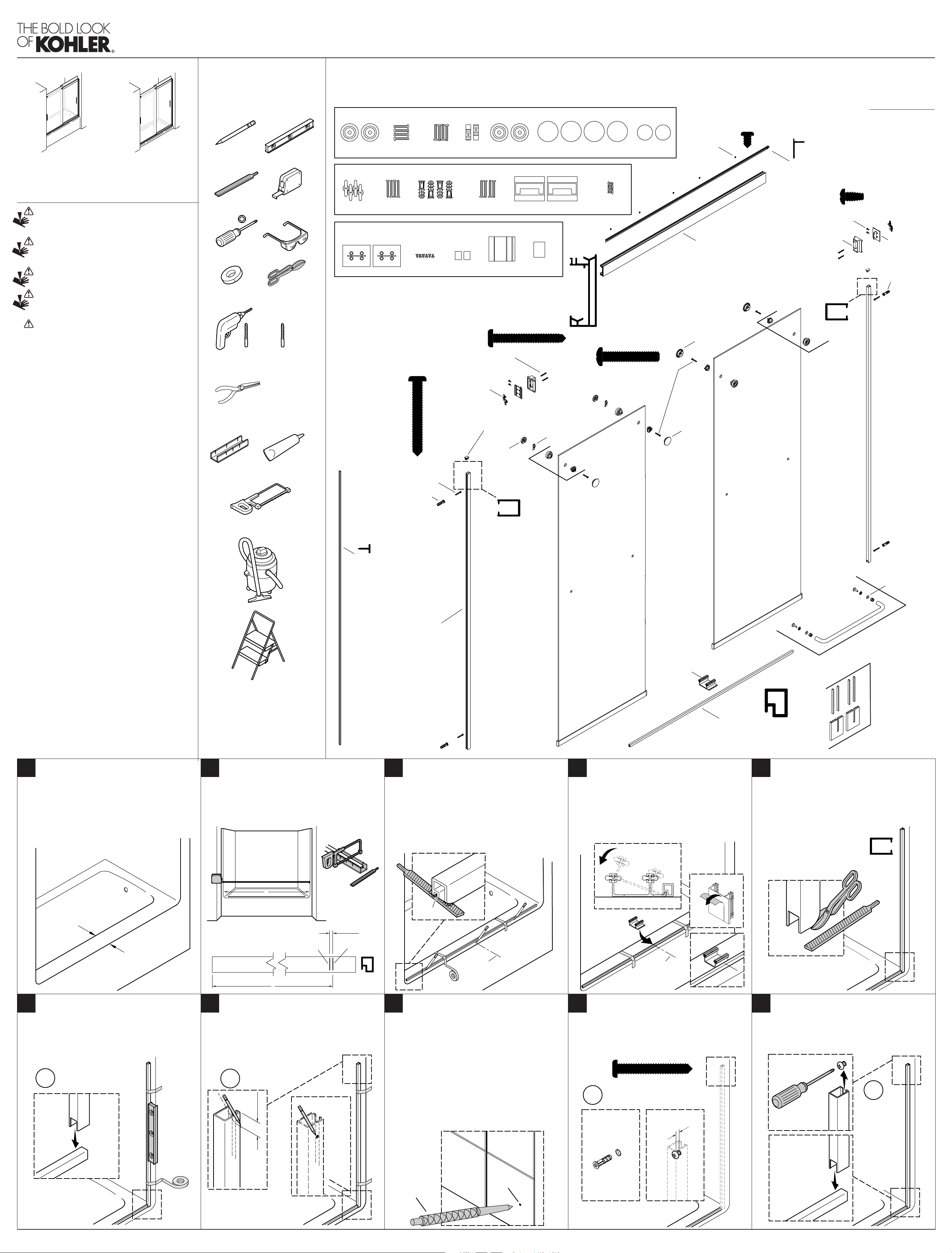
Required Tools Parts Identifi cation
1198346**
Skin Pack
Screw
#10-24 x 1-1/4"
Screw
#8-18 x 1-1/2"
Masking Tape
Inside Roller
1260190**
Bubble Pack
Anchor
1260250* (Center Guide)
Skin Pack
Tin Snips
#10-24 x 1-3/8"
Wall Anchor
Screw
#6-20 x 1/4"Cleat
#10-16 x 1-1/2"
Wall Jamb
Cap
Outside Roller
Screw
Center
Guide
K-70600, K-706001, K-706002, K-706004, K-706005, K-706006, K-706008, K-706009, K-706014, K-706015
Need help? Contact the KOHLER Customer Care Center at 1-800-4KOHLER (1-800-456-4537)
For service parts information *
**Finish/color code must be specifi ed when ordering.
Retain this document for future servicing.
Record model number from box for reference.
Model Number:______________
#6-20 x 1/4"
1049033-D
Screw
1197564-01** [60" (1524 mm)]
1197564-02** [48" (1219 mm)]
Header
1197566-01**
Retainer
1186360**
Bumper Cover
1042520-G (#8-18 x 3/8")
Screw
1188940-01**
Cleat
1260672
Wall Anchor
Bumper
Alcohol
Wipe
Roller Cap Roller PlugClipScrew
Screw
#8-18 x 3/8"
WARNING: Risk of serious injury. Always wear safety
glasses while moving, installing, cutting, or drilling the
glass panels.
IMPORTANT! Do not touch the edges of the tempered glass
with tools or any other hard objects. Do not set the unframed
tempered glass directly on the floor or any hard surface.
IMPORTANT! Leave this manual for the end user.
NOTICE: The warranty does not apply to product that has
been modified or altered in a manner other than as expressly
permitted in the Installation and Care Guide.
Read and follow all instructions before installing or using this
product.
Walls must be within 3/8” (10 mm) of plumb.
Follow the silicone sealant manufacturer’s instructions for
application and curing time.
9/64"
5/32"
1/4"
Pliers
Miter Box
32 Teeth Per Inch Blade
1/4", 5/16"
Masonry Bit
for Tile
100% Silicone Sealant
#10-16 x 1-1/2"
1049043-D
Screw
1260672
Wall Anchor
1077762
Anchor
1195781**
Roller Plug
1048208-C (#8-18 x 1-1/2")
Screw
1181060**
Wall Jamb Cap
1262337
Outside
Roller
1208955**
Clip
1198328-A
Screw
(#10-24 x 1-1/4")
1187908**
Roller Cap
1187908**
Roller Cap
1262336
Inside Roller
Inside Door Panel*
Step Stool
1264187-01**
1264187-02** [78-1/4" (1988 mm)]
Seal (Service Only)
1262423-01** [58" (1473 mm)]
1262423-02** [70" (1778 mm)]
1262423-03** [56" (1422 mm)]
1262423-04** [78" (1981 mm)]
Wall Jamb
[58" (1473 mm)]
Outside Door Panel*
1263090**
Center Guide
1179922-01** [60" (1524 mm)]
1179922-02** [48" (1219 mm)]
Threshold
1057704-01**
1057704-03**
Towel Bar
1187796**
Handles with
Templates
1093027
Washer (8 ea.)
[24" (610 mm)]
[18" (457 mm)]
Measure the Ledge:
1 2
Confirm the ledge is at least 2-1/2” (64 mm) wide. Do
not install the door if there is not 2-1/2” (64 mm) of
width.
Cover the drain with tape to avoid loss of small parts.
2-1/2"
(64 mm)
Measure and Cut the Threshold:
Measure distance “A.”
Mark distance “A” on the threshold.
Subtract 1/4” (6 mm) from “A” and make a second
mark.
Cut the threshold at the second mark.
A
1/4"
(6 mm)
Cut Line
"A" Mark
Position the Threshold:
3
If needed, file the ends of the threshold to match the
corner radius. The threshold must sit flat.
Install the threshold as close to the front of the ledge as
possible. Mark the location.
Tape the threshold in place.
Mark the exact center of the shower ledge.
Groove
Centerline
Install the Center Guide:
4
Clean the center guide location behind the threshold
with an alcohol wipe.
Remove the backing (1) from the adhesive strips on the
center guide.
Align and rotate the center guide into place (2) with the
center marks on the guide and threshold aligned.
Press the center guide firmly into place (3).
2
1
3
Centerline
Prepare the Wall Jambs:
5
IMPORTANT! The threshold and wall jamb must fit
tightly against the ledge and wall.
Position the wall jamb over the threshold.
If needed, trim and file the ends to match radius
corners.
Install the Wall Jambs:
Position the wall jambs over the threshold.
Plumb using a level.
Tape the wall jambs in place.
x2
A
Locate the Wall Jamb Anchors:
7
On each side of the wall jamb, measure 1” (25 mm)
down and mark the side of the wall jamb.
Remove the wall jamb. Mark the center point between
the marks.
x2
1"
(25 mm)
Tile Installations Only:
86
Mark the tile at the hole location before drilling by
carefully tapping the mark with a center punch. This
keeps the drill bit from moving as the hole is started.
When installing to a tile wall, first drill a small
diameter hole, then the correct size hole.
Install anchors. Do not install the screws directly into
the tile, as this may crack the tile.
When drilling, use a masonry bit.
Center
Punch
Mark
Install the Top Wall Jamb Anchors:
9
Drill a 1/4” hole at each mark.
Install the provided wall anchors.
Install the two #10-16 x 1-1/2” screws, one for each
wall jamb, leaving a 1/8” (3 mm) gap between the
screwhead and the wall.
#10-16 x 1-1/2"
x2
1/8"
(3 mm)
Install the Wall Jambs:
10
Slide each wall jamb onto the top screw, then down
over the threshold.
IMPORTANT! The jambs must be tight against the
wall. Adjust the screws as needed.
x2
1201264-2-E
1
Page 2
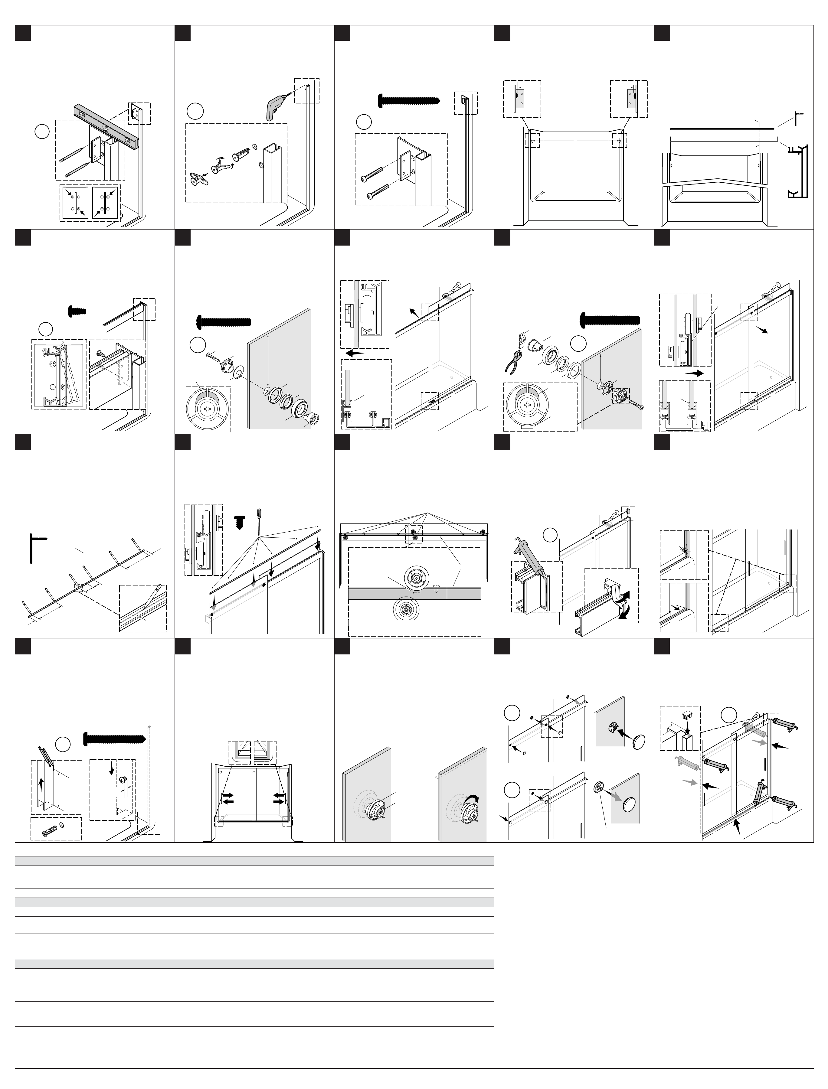
Locate the Cleats:
11 12
IMPORTANT! Each cleat must contact the side of the
wall jamb and be level with the top.
Position a cleat in contact with the wall jamb, top of the
cleat level with the top of the wall jamb.
Mark two holes diagonally.
IMPORTANT! Do not use holes across from each other.
Install the Anchors:
Drill 5/16” holes at the two diagonal cleat marks.
Insert the anchors.
Install the Cleats:
13
IMPORTANT! Each cleat must be level with the top of
the wall jamb and in contact with the wall jamb.
Align the cleat with the wall jamb and secure with two
#8-18 x 1-1/2” screws.
NOTE: The second set of holes can be used if the first
set is not correctly aligned. Repeat step 11 if needed.
Measure the Header and Retainer Length:
14
Measure distance “B” between the screwheads.
Subtract 1/16” (2 mm) from “B” for the final dimension.
B
Cut the Retainer and Header:
15
IMPORTANT! Confirm your measurements before
cutting. Do not cut too short.
Measure and mark dimension “B - 1/16” ( 2 mm) on the
header.
Cut the header at the mark.
Measure and mark dimension “B - 1/16” (2 mm) on the
retainer.
Cut the retainer at the mark.
File any rough edges.
x2
Install the Header:
Rotate the header, flat side out, into place on the cleats.
Secure to each cleat with two #8-18 x 3/8” self-drilling
screws from inside the shower.
Carefully and thoroughly clean the top track, making
sure there is no debris on the roller groove.
x2
3
2
1
Assemble the Inside Panel:
17
IMPORTANT! The inside panel measures 5” (140
mm) from hole to top of the glass.
Assemble and install the inside rollers, tab on top, and
#10-24 x 1-1/4” screws in the upper holes.
Securely tighten the screw.
NOTE: The inside panel is positioned with the rollers
toward the entry (outside) of the shower module.
#8-18 x 1-1/2"
x2
Install the Inside Panel:
1816
With help, from inside the shower lift the inside panel
over the guide and into the lower track on the header.
Confirm the channel on the bottom of the door panel is
engaged with the inside leg on the center guide.
B
Assemble the Outside Panel:
19
Install an outside roller, clip, and #10-24 x 1-1/4” screw
in each upper hole.
Hold the anti-jump clip with a pliers, hook down in the
6 o’clock positon, as the screw is tightened.
Securely tighten the screw.
Cut Line
"B - 1/16" (2 mm) Mark
Install the Outside Panel:
20
With help, lift the outside panel onto the outside leg of
the guide, then onto the upper track.
If immediate adjustment of either door panel is needed,
see Step 28.
Retainer
Header
#8-18 x 3/8"
x2
Install the Retainer:
IMPORTANT! Position the screws at the dimensions
shown.
On the top of the retainer, mark the centerline.
On the top of the retainer, mark the hole locations in the
channel at the locations shown.
Drill six 5/32” holes in the retainer at the marks.
Remove all burrs.
Inside
#10-24 x 1-1/4"
Label on this
x2
x2
Orient tab
on top.
Install the Retainer:
22 2321 24 25
Slide the retainer between the panels.
Secure the retainer to the header with six screws.
Side View
Screw
Gasket
Cam
#6-20 x 1/4"#6-20 x 1/4"
Side of Glass
5"
(127 mm)
Gasket
Spacer
Roller
Axle
Lower
Track
Inside
Inside Leg
Confirm Correct Retainer and Roller Installation:
Confirm the retainer is in the correct position, secured
with six screws.
Confirm the top portion of the rollers on the inside
panel are behind the retainer.
Confirm the anti-jump clips on the outside panel are
oriented downward.
Screws
Clip
Roller
SpacerSpacer
Install the Bumpers:
Apply 100% silicone sealant to both sides of the cleat.
Position a bumper over the top track, engaged in the
rail. Close the bumper.
Slide the bumper along the track and press tight to the
cleat.
Repeat with the second bumper (the second bumper
installs with the opening opposite the first bumper).
Axle
Gasket
Orient tab
on top.
Orient clip
down.
x2
x2
#10-24 x 1-1/4"
Label on this
Side of Glass
3-1/8"
3-1/8"
(79 mm)
(79 mm)
Gasket
Cam
Outside Panel
Upper
Track
Outside
Outside
Outside
Leg
Check Frame Alignment:
Slide the door panels back and forth.
If the outside door panel contacts the wall jamb, remove
the tape on the threshold. If there is no contact, go to the
next step.
Adjust the wall jamb outward until contact is
eliminated. Tape the threshold in place on this side.
Repeat with the opposite wall jamb.
Confirm the threshold is parallel with the front ledge.
Adjust if needed.
Retainer
Profile
1-1/2"
Centerline
3"
(76 mm)
12"
1-1/2"
(13 mm)
(305 mm)
Install the Bottom Wall Jamb Screws:
On each side of the wall jamb (1), measure 4-1/2” (114
mm) up and mark each side of the wall jamb.
Slide the wall jamb up past the marks. Mark the center
point between the marks.
Remove the wall jambs. Drill a 1/4” hole (2) at each
center mark. Install the provided wall anchors.
Install the two #10-16 x 1-1/2” screws (3), leaving a 1/8”
(6 mm) gap between the screwhead and the wall.
(13 mm)
12"
(305 mm)
Channel
Retainer
Clip
Top of roller must
be covered by the
retainer!
Operation Checklist:
27 2826 29
Confirm the bottom bumpers are installed on the door
panels.
Slide the door panels back and forth.
Confirm the door panels do not rub on the floor.
Confirm the door panels are plumb with the wall jambs.
Confirm the top and bottom bumpers contact the door
panels at the same time.
Go to the next step if adjustment is required.
Final Adjustment:
Adjust the panel height and orientation by loosening
the screws and turning the adjustment cam.
Repeat until the door operates smoothly, then retighten
the screws securely.
Confirm the anti-jump clip is still oriented correctly (see
Step 23).
x2
Install the Roller Caps:
Install the towel bar or handle using the separate
instructions provided.
Snap a cap into place on each of the four rollers.
Install clip caps, flat side down, on the clip side of the
inside rollers.
Apply Silicone Sealant:
30
Press the cap onto the wall jamb.
Apply 100% silicone sealant along the wall jambs inside
and outside the shower, along the threshold outside the
shower, and around the base of the center guide.
Bumper
x2
1
4-1/2"
(114 mm)
#10-16 x 1-1/2"
3
1/8"
(3 mm)
Cam
Screw
2
Troubleshooting
Symptom: Alignment Recommended Action
1. The top of the door panel is tilted away from the wall
or the bottom of the door panel is tilted away from the
wall.
2. The door panel does not touch the bumper. A. Determine whether the door panel top or bottom is closer to the wall, and then adjust the roller closest to the wall.
Symptom: Water Leaks Recommended Action
1. Water leaks between panels. A. When showering, make sure the inside panel is against the showerhead wall.
2. Water leaks between the wall jamb and the door panel. A. Adjust the door panel to line up with the wall jamb.
3. Water leaks under the threshold. A. Check for proper silicone sealant application. See step 30. Apply additional silicone sealant in the leak location.
4. Water leaks around the wall jamb area. A. The notched wall jamb fits over the threshold to cover any miscut or skewed cuts. Seal as directed to ensure proper watertight
Symptom: Operation (open/close) Recommended Action
1. The inside and/or outside panel is difficult to move. A. Ensure a gap exists between the guide and the door panel. If no gap exists, raise the position of the rollers.
2. Rubbing noise during panel movement. A. Ensure the anti-jump clips are straight and not rubbing on the header. See step 23.
A. Remove the roller caps. Loosen the roller screw and rotate the roller cams. Tip: use the roller cap to rotate the cam. See steps 17,
19, and 28.
B. Order the optional seal kit.
seal. See step 30.
B. Ensure the panel is properly engaged over the centerguide. See step 20.
C. Ensure the rollers are properly installed. See steps 17 and 19.
D. Ensure that the hanger bracket is tight to the glass.
B. Ensure the roller screws are the correct size. See steps 17 and 19. Ensure the roller screws are completely tightened.
C. Ensure the retainer is securely tightened. See step 22.
x4
x2
x2
Slot
Warranty
ONE-YEAR LIMITED WARRANTY
KOHLER plumbing products are warranted to be free of defects in material and workmanship for one year from date of
installation.
Kohler Co. will, at its election, repair, replace or make appropriate adjustment where Kohler Co. inspection discloses any such
defects occurring in normal usage within one (1) year after installation. Kohler Co. is not responsible for removal or installation
costs. Use of in-tank toilet cleaners will void the warranty.
To obtain warranty service contact Kohler Co. either through your Dealer, Plumbing Contractor, Home Center or E-tailer, or by
writing Kohler Co., Attn.: Customer Care Center, 444 Highland Drive, Kohler, WI 53044, USA, or by calling 1-800-4-KOHLER
(1-800-456-4537) from within the USA and Canada, and 001-800-456-4537 from within Mexico, or visit www.kohler.com within the
USA, www.ca.kohler.com from within Canada, or www.mx.kohler.com in Mexico.
IMPLIED WARRANTIES INCLUDING THAT OF MERCHANTABILITY AND FITNESS FOR A PARTICULAR PURPOSE
ARE EXPRESSLY LIMITED IN DURATION TO THE DURATION OF THIS WARRANTY. KOHLER CO. AND/OR SELLER
DISCLAIM ANY LIABILITY FOR SPECIAL, INCIDENTAL OR CONSEQUENTIAL DAMAGES. Some states/provinces do
not allow limitations on how long an implied warranty lasts, or the exclusion or limitation of special, incidental or consequential
damages, so these limitations and exclusions may not apply to you. This warranty gives you specific legal rights. You may also
have other rights which vary from state/province to state/province.
This is Kohler Co.’s exclusive written warranty.
21201264-2-E ©2015 Kohler Co.
Page 3

Instructions d'installation et d'entretien
Portes de baignoire et de douche coulissantes
1201264-2-E
Portes de baignoire
coulissantes
USA/Canada: 1-800-4KOHLER
Portes de douche
coulissantes
kohler.com
Mexique: 001-800-456-4537
AVERTISSEMENT: Risque de blessures graves. Des
dommages avant l'installation peuvent entraîner des
éclatements de verre. Inspecter le verre et toutes les
pièces pour y rechercher des dommages avant l'installation.
AVERTISSEMENT: Risque de blessures graves. Une
installation incorrecte peut entraîner des éclatements de
verre. Suivre toutes les instructions d'installation.
AVERTISSEMENT: Risque de blessures graves. Ne pas
couper le verre trempé. Le verre trempé éclate lorsqu'il
est coupé.
AVERTISSEMENT: Risque de blessures graves. La
porte de la douche et les panneaux latéraux peuvent
éclater. Inspecter régulièrement le verre et toutes les
pièces pour y rechercher des dommages, ou des pièces
manquantes ou desserrées.
AVERTISSEMENT: Risque de blessures graves.
Toujours porter des lunettes de sécurité pendant le
déplacement, l'installation, le découpage, ou le perçage
de panneaux de verre.
IMPORTANT! Ne pas toucher les bords du verre trempé avec
des outils ou d'autres objets durs. Ne pas poser le verre trempé
non encadré directement sur le plancher ou sur une surface
dure.
IMPORTANT! Laisser ce manuel pour l'utilisateur final.
AVIS: La garantie ne s'applique pas aux produits qui ont été
modifiés ou altérés d'une autre façon que celle permise de
manière expresse dans le guide d'installation et d'entretien.
Lire et suivre toutes les instructions avant d'installer ou d'utiliser
ce produit.
Les murs doivent être compris dans un rayon de 3/8" (10 mm)
de l'aplomb.
Suivre les instructions du fabricant du mastic à la silicone en ce
qui concerne l'application et le temps de prise.
Outils requis Identifi cation des pièces
1198346**
Skin Pack
Vis
#10-24 x 1-1/4"
Vis
#6-20 x 1/4"
#10-16 x 1-1/2"
1049043-D
1260672
Ancrage mural
Ruban cache
Mèche de maçonnerie
9/64"
1/4", 5/16" pour
5/32"
carrelage
1/4"
Pince
Boîte à onglets
Lame de 32 dents par pouce
Cisailles de
ferblantier
Mastic à la silicone
à 100%
Galet intérieur
1260190
Bulles
Pièce
d'ancrage
1230250* (Guide central)
Skin Pack
#8-18 x 1-1/2"
Tasseau
Vis
#10-24 x 1-3/8"
Ancrage mural
Vis
Capuchon de
montant de mur
Pièce d'ancrage
Vis
Clip
#10-16 x 1-1/2"
1077762
Galet extérieur
Vis
Guide
central
1181060**
Capuchon de
montant de mur
1195781**
Bouchon de galet
K-70600, K-706001, K-706002, K-706004, K-706005, K-706006, K-706008, K-706009, K-706014, K-706015
Butée
Tampon à
l'alcool
1048208-C (#8-18 x 1-1/2")
Vis
1208955**
Clip
1262336
Galet
extérieur
Besoin d'aide? Appeler le centre de services à la clientèle de KOHLER au 1-800-4KOHLER (1-800-456-4537)
Capuchon de galet Bouchon
de galet
Vis
#8-18 x 3/8"
1198328-A (#10-24 x 1-1/4")
Vis (galet intérieur)
Pour tout renseignement sur les pièces de rechange *
**Les codes de fi nition et/ou de couleur doivent être fournis au moment de la commande.
Conserver ce document pour référence.
Noter le numéro de modèle sur le carton d'emballage à titre de référence.
Nº du modèle:______________
#6-20 x 1/4"
1049033-D
Vis
1197566-01**
Dispositif de retenue
1042520-G (#8-18 x 3/8")
Vis
1186360**
1188940-01**
Tasseau
1260672
Ancrage mural
1197564-01** [60" (1524 mm)]
1197564-02** [48" (1219 mm)]
Linteau
1187908**
Capuchon de galet
1187908**
Capuchon
de galet
Panneau de porte intérieur*
Couvercle de butoir
1262337
Galet intérieur
Escabeau
1264187-01** [58" (1473 mm)]
1264187-02** [78-1/4" (1988 mm)]
Joint d'étanchéité (entretien seulement)
1262423-01** [58" (1473 mm)]
1262423-02** [70" (1778 mm)]
1262423-03** [56" (1422 mm)]
1262423-04** [78" (1981 mm)]
Montant de mur
Panneau de porte extérieur*
1263090**
Guide de centre
1179922-01** [60" (1524 mm)]
1179922-02** [48" (1219 mm)]
Seuil
1093027
Rondelle (8)
1057704-01**
1057704-03**
Porte-serviettes
1187796**
Poignées avec
gabarits
[24" (610 mm)]
[18" (457 mm)]
Mesurer le rebord:
1 2
Vérifier que la largeur du rebord est égale à 2-1/2” (64
mm) au moins. Ne pas installer la porte si la largeur
n'est pas égale à 2-1/2” (64 mm).
Couvrir le drain avec du ruban adhésif pour éviter de
perdre les petites pièces.
2-1/2"
(64 mm)
Mesurer et couper le seuil:
Mesurer la distance “A.”
Marquer la distance “A” sur le seuil.
Soustraire 1/4” (6 mm) de “A” et marquer un deuxième
repère.
Couper le seuil au niveau du deuxième repère.
A
1/4"
(6 mm)
Ligne de découpe
Marque "A"
Positionner le seuil:
3
Si nécessaire, limer les extrémités du seuil pour les
adapter à l'arrondi des coins. Le seuil doit reposer à
plat.
Installer le seuil aussi près que possible de l'avant du
rebord. Marquer l'emplacement.
Fixer le seuil en place avec du ruban.
Marquer le centre exact du rebord de la douche.
Rainure
Ligne centrale
Installer le guide central:
4
Nettoyer l'emplacement du guide central à l'arrière du
seuil avec un tampon à l'alcool.
Retirer le dos (1) des bandes adhésives sur le guide
central.
Aligner et tourner le guide central pour le mettre en
place (2) en alignant les repères centraux du guide et du
seuil.
Enfoncer fermement le guide central en place (3).
2
1
3
Ligne
centrale
Préparer le montants de mur:
5
IMPORTANT! Le seuil et le montant de mur doivent
être bien adaptés contre le rebord et le mur.
Placer le montant de mur par-dessus le seuil.
Si nécessaire, couper et limer les extrémités suivant
l'arrondi des coins.
Installer les montants de mur:
Placer les montants de mur par-dessus le seuil.
Mettre d'aplomb en utilisant un niveau.
Mettre les montants de mur en place avec du ruban.
x2
A
Positionner les pièces d'ancrage des montants de mur:
7
Sur chaque côté du montant de mur, mesurer 1” (25
mm) vers le bas et marquer le côté du montant de mur.
Retirer le montant de mur. Marquer le point central
entre les repères.
x2
1"
(25 mm)
Installations de carrelage seulement:
86
Marquer le carrelage à l'emplacement du trou avant
de percer en tapant avec précaution sur le repère avec
un pointeau. Ceci empêche la mèche de se déplacer
lorsqu'on commence à percer le trou.
Lors de l'installation sur un mur de carrelage,
commencer par percer un trou de petit diamètre, puis
un trou de la taille correcte.
Installer les pièces d'ancrage. Ne pas installer les vis
directement dans le carrelage, étant donné que ceci
pourrait fissurer celui-ci.
Utiliser une mèche à maçonnerie lors du perçage.
Repère
Pointeau
Installer les pièces d'ancrage de montants de mur
9
supérieures:
Percer un trou de 1/4” à chaque repère.
Installer les pièces d'ancrage fournies.
Installer les deux vis #10-16 x 1-1/2”, une pour chaque
montant de mur, en laissant un écartement de 1/8” (3
mm) entre la tête de vis et le mur.
#10-16 x 1-1/2"
x2
1/8"
(3 mm)
Installer les montants de mur:
10
Glisser chaque montant de mur sur la vis supérieure,
puis abaisser par-dessus le seuil.
IMPORTANT! Les montants doivent être serrés contre
le mur. Ajuster les vis selon les besoins.
x2
1201264-2-E
3
Page 4

Positionner les tasseaux:
11 12
IMPORTANT! Chaque tasseau doit entrer en contact
avec le côté du montant de mur et être de niveau avec
le dessus.
Positionner un tasseau de manière à ce qu'il soit en
contact avec le montant de mur, haut du niveau du
tasseau avec le haut du montant de mur.
Marquer les deux trous à la diagonale.
IMPORTANT! Ne pas utiliser les trous qui se font face.
x2
Installer les pièces d'ancrage:
Percer des trous de 5/16” sur les deux repères
diagonaux du taquet.
Insérer les pièces d'ancrage.
x2
3
2
1
Installer les tasseaux:
13
IMPORTANT! Chaque tasseau doit être de niveau avec
le dessus du montant de mur et être en contact avec le
montant de mur.
Aligner le tasseau avec le montant de mur et fixer en
place avec deux vis #8-18 x 1-1/2”.
REMARQUE: Le deuxième ensemble de trous peut
être utilisé si le premier ensemble n'est pas aligné
correctement. Répéter l'étape11 si nécessaire.
#8-18 x 1-1/2"
x2
Mesurer la longueur du linteau et du dispositif de
14
retenue:
Mesurer la distance “B” entre les têtes de vis.
Soustraire 1/16” (2 mm) de “B” pour la dimension
finale.
B
B
Couper le dispositif de retenue et le linteau.
15
IMPORTANT! Vérifier les mesures avant de couper.
Ne pas couper trop court.
Mesurer et marquer la dimension “B - 1/16” ( 2 mm) sur
le linteau.
Couper le linteau au niveau du repère.
Mesurer et marquer la dimension “B - 1/16” ( 2 mm) sur
le dispositif de retenue.
Couper le dispositif de retenue au niveau du repère.
Limer tous les bords rugueux.
Ligne de découpe
Repère "B - 1/16" (2 mm)
Dispositif
de retenue
Linteau
Installer le linteau:
Tourner le linteau, côté plat vers l'extérieur, pour le
mettre en place sur les tasseaux.
Fixer sur chaque tasseau avec deux vis auto-perceuses
#8-18 x 3/8”, à partir de l'intérieur de la douche.
Nettoyer avec précaution et à fond le rail supérieur, en
s'assurant de l'absence de débris sur la rainure à galets.
#8-18 x 3/8"
x2
Assembler le panneau intérieur:
17
IMPORTANT! Le panneau intérieur mesure 5” (140
mm) entre le trou et le haut du verre.
Assembler et installer les galets intérieurs, avec la patte
sur le dessus, et les vis #10-24 x 1-1/4” dans les trous
supérieurs.
Serrer solidement les vis.
REMARQUE: Le panneau intérieur est positionné
avec les rouleaux tournés vers l'entrée (extérieur) du
module de la douche.
#10-24 x 1-1/4"
Étiquette sur ce
x2
x2
Orienter la
patte sur le
dessus.
Vis
Joint statique
Came
côté du verre
5"
(127 mm)
Joint statique
Espaceur
Installer le panneau intérieur:
1816
Avec de l'aide, lever le panneau intérieur par-dessus le
guide à partir de l'intérieur de la douche, pour le poser
dans le rail inférieur du linteau.
Vérifier que le canal se trouvant sur le bas du panneau
de porte est engagé avec la jambe intérieure sur le guide
central.
Intérieur
Rail
inférieur
Intérieur
Jambe
intérieure
Assembler le panneau extérieur:
19
Installer un rouleau extérieur, ainsi qu'une agrafe et une
vis #10-24 x 1-1/4” dans chaque trou supérieur.
Tenir l'agrafe anti-saut avec une pince, accrocher dans
la position de 6 heures lors du serrage de la vis.
Serrer la vis solidement.
Clip
Axe
#10-24 x 1-1/4"
x2
Galet
Espaceur
Joint statique
Orienter la
patte sur le
dessus.
3-1/8"
(79 mm)
Came
Étiquette sur
ce côté du
verre
Joint
statique
Installer le panneau extérieur:
20
Avec de l'aide, lever le panneau extérieur pour le
mettre sur la jambe extérieure du guide, puis sur le rail
supérieur.
Aller à l'étape 28 si un ajustement immédiat d'un
panneau de porte est nécessaire.
Rail
supérieur
Extérieur
Jambe
extérieure
Extérieur
Installer le dispositif de retenue:
IMPORTANT! Placer les vis aux dimensions
indiquées.
Marquer la ligne centrale sur le dessus du dispositif de
retenue.
Sur le dessus du dispositif de retenue, marquer
les emplacements des trous dans le canal aux
emplacements indiqués.
Percer six trous de 5/32” dans le dispositif de retenue
au niveau des repères.
Éliminer toutes les bavures.
Profil de dispositif
de retenue
1-1/2"
Ligne centrale
(13 mm)
12"
(305 mm)
Orienter le
Galet
Axe
Installer le dispositif de retenue:
22 2321 24 25
Enfiler le dispositif de retenue entre les panneaux.
Fixer le dispositif de retenue sur le linteau avec six vis.
Vue latérale
#6-20 x 1/4"#6-20 x 1/4"
Vérifier que le dispositif de retenue et les galets sont
installés correctement:
Vérifier que le dispositif de retenue est dans la position
correcte, fixer en place avec six vis.
Vérifier que la partie supérieure des galets se trouvant
sur le panneau intérieur se trouve à l'arrière du
dispositif de retenue.
Vérifier que les clips anti-saut se trouvant sur le
panneau extérieur sont dirigées vers le bas.
Vis
Installer les butoirs:
Appliquer du mastic à la silicone à 100% sur les deux
côtés du tasseau.
Positionner un butoir par-dessus le rail supérieur, en
l'engageant dans le rail. Fermer le butoir.
Faire glisser le butoir le long du rail et appuyer pour
qu'il soit bien serré sur le tasseau.
Répéter avec le deuxième butoir (le deuxième butoir est
installé avec l'ouverture sur le côté opposé du premier
butoir).
clip vers le
bas.
Panneau extérieur
x2
Dispositif
Clip
de retenue
Vérifier l'alignement du cadre:
Faire glisser les panneaux de porte vers l'avant et vers
l'arrière.
Si le panneau de porte extérieur entre en contact avec le
montant de mur, retirer le ruban sur le seuil. S'il n'y a
pas de contact, passer à l'étape suivante.
Ajuster le montant de mur vers l'extérieur, jusqu'à ce
que le contact soit éliminé. Mettre le seuil en place avec
du ruban sur ce côté.
Répéter avec le montant de mur opposé.
Vérifier que le seuil est parallèle au rebord avant.
Effectuer les ajustements nécessaires.
3"
(76 mm)
12"
1-1/2"
(13 mm)
(305 mm)
Installer les vis des montants de mur inférieurs:
Sur chaque côté du montant de mur (1), mesurer 4-1/2”
(114 mm) vers le haut et marquer chaque côté du
montant de mur.
Faire glisser le montant de mur vers le haut, au-delà des
repères. Marquer le point central entre les repères.
Retirer les montants de murs. Percer un trou de 1/4” (2)
au niveau de chaque repère central. Installer les pièces
d'ancrage fournies.
Installer les deux vis #10-16 x 1-1/2” (3), en laissant un
écartement de 1/8” (6 mm) entre la tête de vis et le mur.
x2
1
#10-16 x 1-1/2"
3
Canal
Le dessus du galet
doitêtre recouvert
par le dispositif de
retenue!
Liste de vérification de fonctionnement:
27 2826 29
Vérifier que les butoirs inférieurs sont installés sur les
panneaux de porte.
Faire glisser les panneaux de porte vers l'avant et vers
l'arrière.
Vérifier que les panneaux de porte ne frottent pas sur
le sol.
Vérifier que les panneaux de porte sont d'aplomb par
rapport aux montants de mur.
Vérifier que les butoirs supérieurs et inférieurs entrent
en contact avec les panneaux de porte en même temps.
Passer à l'étape suivante si un ajustement est requis.
Butoir
Ajustement final:
Ajuster la hauteur et l'orientation des panneaux en
desserrant les vis et en tournant la came de réglage.
Répétez jusqu'à ce que la porte fonctionne avec
souplesse, puis resserrer les vis solidement.
Vérifier que le clip anti-saut est toujours orientée
correctement (voir l'étape 23).
Installer les capuchons de galets:
Installer le porte-serviettes ou la poignée en utilisant les
instructions séparées fournies.
Encliqueter un capuchon en place sur chacun des quatre
galets.
Installer les capuchons des agrafes, partie avant tournée
vers le bas, sur le côté agrafe des galets intérieurs.
x4
Appliquer du mastic à la silicone:
30
Enfoncer le capuchon sur le montant de mur.
Appliquer du mastic à la silicone à 100% le long des
montants de mur à l'intérieur et à l'extérieur de la
douche, le long du seuil à l'extérieur de la douche, et
autour de la base du guide central.
x2
4-1/2"
(114 mm)
1/8"
(3 mm)
Came
Vis
2
Dépannage
Symptôme: Alignement Action recommandée
1. Le haut du panneau de porte est incliné vers le sens
opposé du mur ou le bas du panneau de porte est incliné
vers le sens opposé du mur.
2. Le panneau de la porte ne touche pas le butoir. A. Déterminer si le haut ou le bas du panneau de porte est le plus proche du mur, puis ajuster le galet qui est le plus proche du mur.
Symptôme: Présence de fuites d'eau Action recommandée
1. Fuites d'eau entre les panneaux. A. Lors de la douche, s'assurer que le panneau intérieur se trouve contre le mur de la pomme de douche.
2. Fuites d'eau entre le montant du mur et le panneau de la
porte.
3. Fuites d'eau sous le seuil. A. Vérifier que le mastic à la silicone est appliqué correctement. Voir l'étape 30. Appliquer du mastic à la silicone supplémentaire à
4. Fuites d'eau autour de la zone du montant de mur. A. Le montant de mur à encoche se place sur le seuil pour couvrir toute mauvaise coupe ou toute coupe asymétrique. Mastiquer
Symptôme: Fonctionnement (ouverture/fermeture) Action recommandée
1. Le panneau intérieur et/ou extérieur est difficile à
déplacer.
2. Bruit de frottement durant le mouvement du panneau. A. Vérifier que les clips anti-saut sont droits et ne frottent pas sur le linteau. Voir l'étape 23.
A. Retirer les capuchons de galet. Desserrer la vis de galet et faire pivoter les cames de galet. Conseil: utiliser le capuchon de galet
pour faire pivoter la came. Voir les étapes 17, 19 et 28.
A. Ajuster le panneau de la porte pour l'aligner sur le montant du mur.
B. Commander le kit d'étanchéité optionnel.
l'emplacement de la fuite.
conformément aux instructions pour assurer une bonne étanchéité à l'eau. Voir l'étape 30.
A. S'assurer qu'il y a un espacement entre le guide et le panneau de la porte. Si aucun écart n'est présent, élever la position des
galets.
B. S'assurer que le panneau est correctement engagé sur le guide central. Voir l'étape 20.
C. S'assurer que les galets sont installés correctement. Voir les étapes 17 et 19.
D. Vérifier que l'étrier de suspension est serré contre le verre.
B. S'assurer que la taille des vis de galets est correcte. Voir les étapes 17 et 19. Assurer que les vis des galets sont entièrement serrées.
C. Assurer que le dispositif de retenue est attaché en toute sécurité. Voir l'étape 22.
x2
Encoche
Garantie
GARANTIE LIMITÉE D'UN AN
Les produits de plomberie KOHLER sont garantis contre tout vice de matériau et de fabrication pendant un an à partir de la date
de l'installation.
Si un vice est découvert au cours d'une utilisation normale, Kohler Co. choisira, à sa discrétion, la réparation, le remplacement ou
la rectification appropriée après inspection desdits vices par Kohler Co. pendant un (1) an à partir de la date d'installation. Kohler
Co. n'est pas responsable des frais d'enlèvement ou d'installation. L'utilisation de nettoyants à l'intérieur du réservoir annule la
garantie.
Pour obtenir le service de garantie, contacter Kohler Co., par l'intermédiaire du vendeur, plombier, centre de rénovation ou
revendeur par internet, ou bien par écrit à l'adresse suivante Kohler Co., Attn.: Customer Care Center, 444 Highland Drive, Kohler,
WI 53044, USA, ou appeler le 1-800-4-KOHLER (1-800-456-4537) à partir des É.-U. et du Canada, et le 001-800-456-4537 à partir
du Mexique, ou consulter le site www.kohler.com aux É.-U., www.ca.kohler.com à partir du Canada, ou www.mx.kohler.com au
Mexique.
LES GARANTIES TACITES, Y COMPRIS CELLES DE COMMERCIALITÉ ET D'ADAPTATION À UN USAGE
PARTICULIER, SONT EXPRESSÉMENT LIMITÉE À LA DURÉE DE LA PRÉSENTE GARANTIE. KOHLER CO. ET/OU LE
REVENDEUR DÉCLINENT TOUTE RESPONSABILITÉ CONTRE LES DOMMAGES PARTICULIERS, ACCESSOIRES OU
INDIRECTS. Certains états et provinces ne permettent pas de limite sur la durée de la garantie tacite, ni l'exclusion ou la limite
des dommages particuliers, accessoires ou indirects, et, par conséquent, lesdites limites et exclusions peuvent ne pas s'appliquer
à votre cas. Cette garantie vous donne des droits juridiques particuliers. Vous pouvez également avoir d'autres droits qui varient
d'un état ou d'une province à l'autre.
Ceci constitue la garantie écrite exclusive de Kohler Co.
41201264-2-E ©2015 Kohler Co.
Page 5

Instrucciones de instalación y cuidado
Puertas corredizas de bañera y de ducha
1201264-2-E
Puertas corredizas
de bañera
Puertas corredizas
de ducha
EE.UU./Canadá: 1-800-4KOHLER
México: 001-800-456-4537
ADVERTENCIA: Riesgo de lesiones graves. Daños
previos a la instalación podrían ocasionar que el vidrio se
quiebre en pedazos. Antes de hacer la instalación revise
el vidrio y todas las piezas para ver si presentan daños.
ADVERTENCIA: Riesgo de lesiones graves. Si la
instalación se hace de manera incorrecta, el vidrio podría
quebrarse en pedazos. Siga todas las instrucciones de
instalación.
ADVERTENCIA: Riesgo de lesiones graves. No corte
vidrio templado. El vidrio templado se quiebra en
pedazos si se corta.
kohler.com
Herramientas requeridas Identifi cación de piezas
1198346**
Paquete al vacío
Tornillo
#10-24 x 1-1/4"
Tornillo
#8-18 x 1-1/2"
#6-20 x 1/4"
Cinta de
enmascarar
Rueda interior
1260190
Paquete de burbujas
Anclaje
1260250* (guía central)
Paquete al vacío
Tablilla de sujeción
Tijeras para
chapa
Tornillo
#10-24 x 1-3/8"
Anclaje de pared
Tornillo
Tapa de la
jamba mural
Rueda exterior
Tornillo
#10-16 x 1-1/2"
Guía
central
K-70600, K-706001, K-706002, K-706004, K-706005, K-706006, K-706008, K-706009, K-706014, K-7060150
¿Necesita ayuda? Comuníquese con el Centro de Atención al Cliente de KOHLER al 1-800-4KOHLER (1-800-456-4537)
para obtener información sobre piezas de repuesto.*
**Se debe especifi car el código del acabado/color con el pedido.
Guarde este documento para servicio futuro.
Anote el número de modelo de la caja como referencia.
Número de modelo:______________
#6-20 x 1/4"
1049033-D
Tornillo
1197564-01** [60" (1524 mm)]
1197564-02** [48" (1219 mm)]
Dintel
1197566-01**
Retenedor
1186360**
Tapa de tope
1042520-G (#8-18 x 3/8")
Tornillo
1188940-01**
Tablilla de
sujeción
1260672
Anclaje de
pared
Tope
Paño humedecido
en alcohol
Tapa de rueda Tapón de ruedaClip
Tornillo
#8-18 x 3/8"
ADVERTENCIA: Riesgo de lesiones graves. La puerta
y los paneles laterales de la ducha podrían quebrarse en
pedazos. Revise con regularidad el vidrio y todas las
piezas para ver si presentan daños, si algo falta o si hay
piezas sueltas.
ADVERTENCIA: Riesgo de lesiones graves. Siempre
use anteojos de seguridad al mover, instalar o cortar los
paneles de vidrio o de taladrar en ellos.
¡IMPORTANTE! No toque los filos del vidrio templado con
herramientas ni con ningún otro objeto duro. No ponga el vidrio
templado sin marco directamente sobre el piso ni sobre ninguna
otra superficie dura.
¡IMPORTANTE! Deje este manual para el usuario final.
AVISO: La garantía no se aplica a producto que haya sido
modificado o alterado de alguna forma que no sea alguna
de las permitidas expresamente en la Guía de instalación y
cuidado.
Lea y siga todas las instrucciones antes de instalar o de utilizar
este producto.
Las paredes deben estar a menos de 3/8" (10 mm) de estar a
plomo.
Siga las instrucciones de aplicación y de tiempo de secado del
fabricante del sellador de silicona.
9/64"
5/32"
1/4"
Pinzas
Caja de ingletes
Hoja de sierra de 32 dientes por pulgada
Broca para
mampostería de
1/4", 5/16" para
azulejo
Sellador 100% de
silicona
#10-16 x 1-1/2"
1049043-D
Tornillo
1260672
Anclaje de pared
1048208-C (#8-18 x 1-1/2")
Tornillo
1077762
Anclaje
1181060**
Tapa de jamba mural
1195781**
Tapón de rueda
1262336
Rueda
exterior
1208955**
Clip
1198328-A (#10-24 x 1-1/4")
Tornillo (rueda interior)
1187908**
Tapa de rueda
1187908**
Tapa de
rueda
1262337
Rueda interior
Panel de puerta interior*
Taburete escalera
1264187-01** [58" (1473 mm)]
1264187-02** [78-1/4" (1988 mm)]
Sello (solo para servicio)
1262423-01** [58" (1473 mm)]
1262423-02** [70" (1778 mm)]
1262423-03** [56" (1422 mm)]
1262423-04** [78" (1981 mm)]
Jamba mural
Panel de puerta exterior*
1263090**
Guía central
1179922-01** [60" (1524 mm)]
1179922-02** [48" (1219 mm)]
Umbral
1093027
Arandela (8 c/u)
1057704-01**
1057704-03**
Toallero de barra
1187796**
Manijas con
plantillas
[24" (610 mm)]
[18" (457 mm)]
Mida el reborde:
1 2
Confirme que el reborde mida por lo menos 2-1/2” (64
mm) de ancho. No instale la puerta si no hay 2-1/2” (64
mm) de ancho.
Cubra el desagüe con cinta de enmascarar para evitar
perder piezas pequeñas.
2-1/2"
(64 mm) Min
Mida y corte el umbral:
Mida la distancia “A”.
Marque la distancia “A” en el umbral.
Reste (6 mm) de “A” y haga una segunda marca.
Corte el umbral en la segunda marca.
A
1/4"
(6 mm)
Línea de corte
Marca "A"
Coloque el umbral en su lugar:
3
De ser necesario, lime los extremos del umbral para
igualarlos al radio de las esquinas. El umbral debe
quedar bien asentado.
Instale el umbral lo más cerca posible del frente del
reborde. Marque la ubicación.
Aplique cinta adhesiva para sostener el umbral en su
lugar.
Marque el centro exacto del reborde de la ducha.
Ranura
Línea de
centros
Instale la guía central:
4
Con el paño humedecido en alcohol, limpie el lugar
para la guía central detrás del umbral.
Retire el papel protector (1) de las tiras adhesivas en la
guía central.
Alinee y gire la guía central a su lugar (2) de manera
que las marcas centrales en la guía y en el umbral
queden alineadas.
Oprima la guía central con firmeza en su lugar (3).
2
1
3
Línea de
centros
Prepare las jambas murales:
5
¡IMPORTANTE! El umbral y la jamba mural deben
quedar a plomo con el reborde y la pared.
Coloque la jamba mural sobre el umbral.
De ser necesario, recorte y lime los extremos para
igualar el radio de las esquinas.
Instale las jambas murales:
Coloque las jambas murales sobre el umbral.
Ponga a plomo con un nivel.
Con cinta de enmascarar pegue las jambas murales en
su lugar.
x2
A
Ubique los anclajes de las jambas murales:
7
A cada lado de la jamba mural mida 1” (25 mm) hacia
abajo, y marque el lado de la jamba mural.
Retire la jamba mural. Marque el punto central entre las
marcas.
x2
1"
(25 mm)
Solo en instalaciones en azulejo:
86
Antes de taladrar haga con cuidado una marca en el
azulejo en el lugar del orificio. Esto evita que la broca
se mueva al comenzar a taladrar el orificio.
Al instalar en una pared de azulejo, primero taladre
un orificio de poco diámetro, y luego un orificio más
grande.
Instale anclajes. No instale tornillos directamente en el
azulejo, ya que esto podría fisurar el azulejo.
Al taladrar, utilice una broca para mampostería.
Marca
Punzón
Instale los anclajes de la jamba mural superior:
9
Taladre un orificio de 1/4" en cada marca.
Instale los anclajes de pared que se incluyen.
Instale los dos tornillos #10-16 x 1-1/2”, uno en cada
jamba mural, y deje una separación de 1/8” (3 mm)
entre la cabeza del tornillo y la pared.
#10-16 x 1-1/2"
x2
1/8"
(3 mm)
Instale las jambas murales:
10
Deslice cada jamba mural hacia el tornillo superior, y
luego hacia abajo sobre el umbral.
¡IMPORTANTE! Las jambas deben quedar apretadas
contra la pared. Ajuste los tornillos lo que sea necesario.
x2
1201264-2-E
5
Page 6

Ubique las tablillas de sujeción:
11 12
¡IMPORTANTE! Cada una de las tablillas de sujeción
debe hacer contacto con el lado de la jamba mural y
estar nivelada con la parte superior.
Coloque una tablilla de sujeción en contacto con la
jamba mural, la parte superior de la tablilla de sujeción
nivelada con la parte superior de la jamba mural.
Marque 2 orificios diagonalmente.
¡IMPORTANTE! No use orificios que estén uno frente
al otro.
Instale los anclajes:
Taladre orificios de 5/16" en las dos marcas diagonales
de la tablilla de sujeción.
Introduzca los anclajes.
Instale las tablillas de sujeción:
13
¡IMPORTANTE! Cada una de las tablillas de sujeción
debe quedar nivelada con la parte superior de la jamba
mural y en contacto con la jamba mural.
Alinee la tablilla de sujeción con la jamba mural, y fije
con dos tornillos #8-18 x 1-1/2”.
NOTA: Puede usarse el segundo juego de orificios si el
primer juego no queda bien alineado. Repita el paso 11,
si es necesario.
Mida la longitud del dintel y del retenedor:
14
Mida la distancia “B” sobre las cabezas del tornillo.
Reste 1/16" (2 mm) de la dimensión “B” para obtener la
dimensión final.
B
Corte el retenedor y el dintel:
15
¡IMPORTANTE! Confirme sus medidas antes de cortar.
No corte demasiado corto.
Mida y marque la dimensión “B - 1/16” ( 2 mm) en el
dintel.
Corte el dintel en la marca.
Mida y marque la dimensión “B - 1/16” ( 2 mm) en el
retenedor.
Corte el retenedor en la marca.
Lime los bordes ásperos.
x2
Instale el dintel:
Gire el dintel a su lugar, con el lado plano hacia fuera,
en su lugar en las tablillas de sujeción.
Fíjelo a cada tablilla de sujeción con dos tornillos
autorroscantes #8-18 x 3/8” desde el interior de la
ducha.
Limpie con cuidado y a profundidad el carril superior,
y asegúrese de que no queden partículas residuales en
la ranura para ruedas.
x2
3
2
1
Ensamble el panel interior:
17
¡IMPORTANTE! El panel interior mide 5” (140 mm)
del orificio a la parte superior del vidrio.
Ensamble e instale las ruedas interiores, con la cresta
de la leva hacia arriba, y los tornillos #10-24 x 1-1/4”
en los orificios superiores.
Apriete bien los tornillos.
NOTA: El panel interior se coloca con las ruedas hacia
la entrada (el exterior) del módulo de la ducha.
#8-18 x 1-1/2"
x2
Instale el panel interior:
1816
Con ayuda, desde el interior de la ducha levante el
panel interior sobre la guía y dentro del carril inferior
en el dintel.
Confirme que el canal en la parte inferior del panel de la
puerta encaje con la pata interior en la guía central.
Interior
B
Ensamble el panel exterior:
19
Instale una rueda exterior, un clip, y un tornillo de #1024 x 1-1/4” en cada orificio superior.
Sostenga el clip contra saltos con unas pinzas, enganche
en la posición de las 6 del reloj a medida que aprieta el
tornillo.
Apriete bien el tornillo.
Línea de corte
Marca de "B - 1/16" (2 mm)
Instale el panel exterior:
20
Con ayuda, levante el panel exterior en la pata exterior
de la guía, y luego en el carril superior.
Si es necesario hacer ajustes de inmediato en cualquiera
de los paneles de puerta, consulte el paso 28.
Carril
superior
Retenedor
Dintel
#8-18 x 3/8"
x2
Instale el retenedor:
¡IMPORTANTE! Coloque los tornillos en los lugares
que se indican.
En la parte superior del retenedor, marque la línea de
centros.
En la parte superior del retenedor, marque los lugares
de los orificios en el canal en los lugares indicados.
Taladre seis orificios de 5/32” en las marcas en el
retenedor.
Quite todas las rebabas.
#10-24 x 1-1/4"
Etiqueta en este
x2
x2
Oriente la
cresta de la
leva hacia
arriba.
Instale el retenedor:
22 2321 24 25
Deslice el retenedor entre los paneles.
Fije al retenedor al dintel con seis tornillos.
Vista lateral
Tornillo
Empaque
Leva
#6-20 x 1/4"#6-20 x 1/4"
lado del vidrio
5"
(127 mm)
Empaque
Espaciador
Rueda
Eje
Carril
inferior
Interior
Pata interior
Confirme la instalación correcta del retenedor y de las
ruedas:
Confirme que el retenedor esté en la posición correcta,
fijo con seis tornillos.
Confirme que la parte superior de las ruedas en el panel
interior estén detrás del retenedor.
Confirme que los clips contra saltos en el panel exterior
estén orientados hacia abajo.
Tornillos
Clip
Rueda
Espaciador
Instale los topes:
Aplique sellador 100% de silicona a ambos lados de la
tablilla de sujeción.
Coloque un tope sobre el carril superior, encajado en el
riel. Cierre el tope.
Deslice el tope a lo largo del carril y oprímalo con
firmeza contra la tablilla de sujeción.
Repita con el segundo tope (el segundo tope se instala
con la abertura opuesta al primer tope).
Eje
Empaque
Oriente la
cresta de la
leva hacia
arriba.
Oriente el
clip hacia
abajo.
#10-24 x 1-1/4"
x2
Etiqueta en este
lado del vidrio
3-1/8"
(79 mm)
Empaque
Leva
Panel exterior
Exterior
Exterior
Pata
exterior
Verifique la alineación del marco:
Deslice los paneles de puerta en ambos sentidos.
Si el panel de la puerta exterior hace contacto con la
jamba mural, retire la cinta adhesiva del umbral. Si no
hay contacto, haga el siguiente paso.
Ajuste la jamba mural hacia fuera hasta que se haya
eliminado el contacto. Pegue el umbral en su lugar en
este lado.
Repita con la jamba mural opuesta.
Confirme que el umbral quede paralelo al reborde
frontal. Ajuste si es necesario.
Perfil del
retenedor
1-1/2"
Línea de centros
3"
(76 mm)
12"
1-1/2"
(13 mm)
(305 mm)
Instale los tornillos de la jamba mural inferior:
A cada lado de la jamba mural (1) mida 4-1/2” (114
mm) hacia arriba, y marque cada lado de la jamba
mural.
Deslice la jamba mural hacia arriba más allá de las
marcas. Marque el punto central entre las marcas.
Retire las jambas murales. Taladre un orificio de 1/4"
(2) en cada marca central. Instale los anclajes de pared
que se incluyen.
Instale los dos tornillos #10-16 x 1-1/2” (3), y deje una
separación de 1/8” (6 mm) entre la cabeza del tornillo y
la pared.
(13 mm)
12"
(305 mm)
Canal
Retenedor
Clip
¡La rueda superior
debe estar cubierta
por el retenedor!
Lista de verificación del funcionamiento:
27 2826 29
Confirme que los topes inferiores estén instalados en los
paneles de puerta.
Deslice los paneles de puerta en ambos sentidos.
Confirme que los paneles de puerta no rocen contra el
piso.
Confirme que los paneles de puerta estén a plomo con
las jambas murales.
Confirme que los topes superior e inferior hagan
contacto con los paneles de puerta al mismo tiempo.
Realice el siguiente paso si es necesario hacer ajustes.
Ajuste final:
Para ajustar la altura y la orientación de los paneles hay
que aflojar los tornillos y girar la leva de ajuste.
Repita hasta que la puerta funcione sin dificultades, y
luego vuelva a apretar los tornillos con firmeza.
Confirme que el clip contra saltos siga orientado
correctamente (consulte el paso 23).
x2
Instale las tapas de las ruedas:
Instale el toallero de barra o la manija de acuerdo a las
instrucciones que se entregan por separado.
Encaje una tapa en su lugar en cada una de las cuatro
ruedas.
Instale las tapas de los clips, con el lado plano hacia
abajo, en el lado del clip de las ruedas interiores.
x4
Aplique sellador de silicona:
30
Presione la tapa en la jamba mural.
Aplique sellador 100% de silicona a lo largo de las
jambas murales dentro y fuera de la ducha, a lo largo
del umbral fuera de la ducha, y alrededor de la base de
la guía central.
x2
Tope
x2
1
4-1/2"
(114 mm)
#10-16 x 1-1/2"
3
1/8"
(3 mm)
Leva
Tornillo
2
Resolución de problemas
Síntoma: Alineación Acción recomendada
1. La parte superior del panel de puerta está inclinada hacia
fuera de la pared, o la parte inferior del panel de puerta
está inclinada hacia fuera de la pared.
2. El panel de puerta no hace contacto con el tope. A. Determine si la parte superior o si la parte inferior del panel de puerta está más cerca de la pared, y luego ajuste la rueda que esté
Síntoma: Fugas de agua Acción recomendada
1. Se fuga agua entre los paneles. A. Al ducharse, asegúrese de que el panel interior esté contra la pared donde está la cabeza de ducha.
2. Se fuga agua entre la jamba mural y el panel de puerta. A. Ajuste el panel de puerta para que quede alineado con la jamba mural.
3. Se fuga agua por debajo del umbral. A. Verifique que el sellador de silicona esté bien aplicado. Consulte el paso 30. Aplique más sellador de silicona en el lugar de la
4. Se fuga agua por el área de las jambas murales. A. La jamba mural con muescas queda sobre el umbral para cubrir cortes mal hechos o sesgados. Selle como se indica para asegurar
Síntoma: Funcionamiento (abrir/cerrar) Acción recomendada
1. El panel interior y/o el exterior se mueven con
dificultad.
2. Ruido de roce al mover el panel. A. Asegúrese de que los clips contra saltos estén derechos y que no rocen en el dintel. Consulte el paso 23.
A. Retire las tapas de rueda. Afloje el tornillo de rueda y gire las levas de rueda. Sugerencia: Utilice la tapa de rueda para girar la
leva. Vea los pasos 17, 19 y 28.
más cerca de la pared.
B. Pida el kit de sello opcional.
fuga.
que el sello sea correcto e impermeable. Consulte el paso 30.
A. Asegúrese de que haya una separación entre la guía y el panel de puerta. Si no hay separación, eleve la posición de las ruedas.
B. Asegúrese de que el panel esté bien encajado sobre la guía central. Consulte el paso 20.
C. Asegúrese de que las ruedas estén bien instaladas. Vea los pasos 17 y 19.
D. Asegúrese de que el soporte de suspensión esté apretado contra el vidrio.
A. Asegúrese de que los tornillos de las ruedas sean del tamaño correcto. Vea los pasos 17 y 19. Asegúrese de que los tornillos de las
ruedas estén completamente apretados.
C. Asegúrese de que el retenedor esté apretado con firmeza. Consulte el paso 22.
x2
Ranura
Garantía
GARANTÍA LIMITADA DE UN AÑO
Se garantizan los productos de plomería KOHLER contra defectos de material y mano de obra durante un año a partir de la fecha
de instalación.
Kohler Co., a su criterio, reparará, reemplazará o realizará los ajustes pertinentes en los casos en que la inspección realizada por
Kohler Co. determine que dichos defectos hayan ocurrido durante el uso normal en el transcurso de un (1) año a partir de la fecha
de instalación. Kohler Co. no se hace responsable de costos de desinstalación o de instalación. El uso de limpiadores de inodoro
que se colocan dentro del tanque anula la garantía.
Para obtener el servicio de garantía, comuníquese con Kohler Co. a través de su distribuidor, contratista de plomería, centro de
remodelación o distribuidor por Internet, o escriba a Kohler Co., Atención: Customer Care Center, 444 Highland Drive, Kohler,
WI 53044, EE.UU., o llame al 1-800-4-KOHLER (1-800-456-4537) desde los EE.UU. y Canadá, o al 001-800-456-4537 desde México, o
visite www.kohler.com desde los EE.UU., www.ca.kohler.com desde Canadá, o www.mx.kohler.com en México.
TODA GARANTÍA IMPLÍCITA, INCLUIDA LA DE COMERCIALIZACIÓN E IDONEIDAD DEL PRODUCTO PARA UN
USO DETERMINADO, SE LIMITA EXPRESAMENTE A LA DURACIÓN DE ESTA GARANTÍA. KOHLER CO. Y/O EL
VENDEDOR DESCARGAN TODA RESPONSABILIDAD POR CONCEPTO DE DAÑOS PARTICULARES, INCIDENTALES
O INDIRECTOS. Algunos estados/provincias no permiten limitaciones en cuanto a la duración de una garantía implícita o a
la exclusión o limitación de daños particulares, incidentales o indirectos, por lo que estas limitaciones y exclusiones pueden no
aplicar a su caso. Esta garantía le otorga ciertos derechos legales específicos. Además, usted también puede tener otros derechos
que varían de estado a estado y de provincia a provincia.
Esta es la garantía exclusiva por escrito de Kohler Co.
61201264-2-E
©2015 Kohler Co.
 Loading...