

Page 1

BEFORE YOU BEGINBEFORE YOU BEGIN
MINIMA
INSTALLATION INSTRUCTIONS
SLIDING, 1 DOOR 1 PANEL
8mm K-45803T-L-SHP
10mm K-45806T-L-SHP
·
Before you install your shower door, please read
these instructions carefully to familiarize yourself
with the required tools, materials, and installation
sequences. Follow the sections that pertain to your
particular installation. This will help you avoid costly
mistakes. In addition to proper installation, read all
operating and safety instructions.
All information is based on the latest product
·
information available at the time of publication.
Kohler China Ltd. reserves the right to make
changes in product characteristics, packaging, or
availability at any time without notice.
These instructions contain important care, cleaning,
·
and warranty information-
instructions for the consumer.
Make sure that the bath and the finished wall
·
material are completely and correctly installed prior
to installing your shower door. Prepare waterproof
layer to wall and floor of the showering area. It is not
allowed for any presence of electric switches and
sockets. Make sure the floor drain runs smoothly.
Before starting the door installation, lay out and
·
identify all the parts. Use the exploded view
illustrated on page 2 for reference.
For the installation method of customized shower
·
with different dimensions, please refer to this
instructions.
CAUTION: Risk of injury or product damage.
Tempered glass cannot be cut, drilled or knocked
by hard object. Make sure corner area of the
glass refraining from knocking so as to cause
personal injury due to broken glass.
ATTENTION:
receptors or curbs. (Not included). If the curb is not
Kohler-branded, please note its top width should be
more than 80mm.
IMPORTANT:
finished wall. The squareness of the wall is
recommended no more than 3 mm/m. KOHLER
Company won't take responsibility of the installation
quality.
Please install this door on Kohler
The shower door requires a flat vertical
please leave these
·
·
·
·
·
2
·
(
) 80mm
3mm/m
1198141-T01-B
-1-
13-1 528437
, 2014
Copyright Kohler China Ltd., 2014
Page 2

ROUGHING-IN
H
B
PARTS IDENTIFICATIONPARTS IDENTIFICATION
IMPORTANT
Unit: mm
SKU B H
K-45803T
K-45806T
1200-1600 1850-2000
Before installation check that all components are
correctly supplied.
If any parts are missing please ring the helpline.
800-820-2628
Top Lintel
Inline Panel
Wall Channel
C
Glass Clamp
800-820-2628
Door Panel
1198141-T01-B
Threshold
Splashguard
-2-
Wall Channel
Cover Seal
Page 3

4mm Allen key
4mm
Top Roller Clamps
Mid-support Clamp
X6
A
B
2.5mm Allen Key
2.5mm
X4
C
Screw Covers
X7
Screw Covers
X4
Support Strip
X2
X2
Bottom Guide
End Socket
Door Closing Guide
Plastic Guides
Frame Cap,LH Frame Cap,RH
X4
Wall Plugs
X7
X2
Wedge
ED
Handle
1198141-T01-B
-3-
Page 4
INSTALLATION REQUIREMENTSINSTALLATION REQUIREMENTS
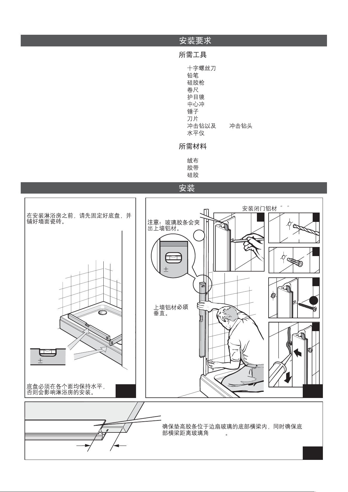
Tools Required
·
Phillips Screwdriver
·
Pencil
·
Caulk Gun
·
Measuring Tape
·
Safety Glasses
·
Center Punch
·
Hammer
·
Knife
·
Masonry Drill & 6mm Drilll Bit
·
Level
Materials Required
·
Drop Cloth
Tape
·
Silicone Sealant
·
INSTALLATION
Fit tray and then tile walls before fitting
the unit.
·
·
·
·
·
·
·
·
·
·
·
·
·
NOTE: Glass seal will
extend out of wall
channel.
A
6mm
Fit Wall Channel 'A'
A
1
X3
6mm
X3
2
0mm
Tray MUST be level in all planes or the
unit will not install properly.
STEP
3
X3
0mm
4
Wall channels
MUST
plumb.
be
A
X3
5
STEP
1
Ensure the support strips are still on the bottom edge
of the inline panel, inside the H section, and that the H
section is 53mm from the corner of the glass.
2
1198141-T01-B
53mm
53mm
STEP
3
-4-
Page 5

Bottom channel fits under
seal.
Caution
Rest panel against
seal of wall channel
'A' .
Support glass
panel until glass
clamp is fitted
A
Check that bottom
channel is parallel to
edge of tray.
.
Glass needs to be at least 8mm
into wall channel
8mm
8mm minimum
8mm
STEP
4
Fit glass clamp and turn screw until it
lightly grips glass.
Glass should
protrude out
of bottom
channel by
53mm.
53mm
0mm
Glass panel
be plumb.
When glass is in
correct position
fully tighten clamp
glass screws.
must
1198141-T01-B
C
X4
STEP
5
STEP
6
-5-
Page 6

Cut seals exposed at top with a sharp knife.
53mm
Mark hole position, remove temporarily the bottom
guide and drill hole into the tray.
Top view
STEP
7
STEP
8
Lay a bead of sealant in bottom guide as shown, then
slide it under glass.
STEP
10
Locate one end of threshold under the bottom guide.
1198141-T01-B
6mm
STEP
9
2
1
STEP
11
-6-
Page 7

Remove
=
=
cover vinyl.
Lay sealant on
bottom of door
closing guide.
Place door
closing guide
under wall
channel.
Keep threshold position parallel to tray edge.
Fit the second wall channel.
X3
0mm
Wall channel
MUST
plumb.
be
X3
A
STEP
12
6mm
X3
STEP
13
Push cover vinyl Into place.
2
3
4
5
1198141-T01-B
Channel fits over
threshold.
STEP
14
-7-
STEP
15
Page 8

Screw bottom
guide to tray.
Position support clamps and sockets on top lintel.
Top view
B
B
STEP
16
1
Turn with allen key to
lightly grip the top lintel.
Fully tighten mid support clamp '2' & loosely fit end sockets '1' & '3'.
213
2
1
2
E
Screw mid support clamp to
lintel.
Turn with allen key to lightly
grip the top lintel.
3
3
Slide lintel and sockets to position.
Place the end socket1&3ontopofglass and wall channels.
13
1
1198141-T01-B
STEP
17
2
3
STEP
18
-8-
Page 9

Screw into wall channel.
X2
D
Place mid support clamp.
Screw mid support clamp
firmly to glass.
Screw 2nd socket to wall
channel then tighten the allen
screws on both sides.
Allen screw
D
STEP
19
Carefully turn door
panel on its edge
and support.
STEP
20
10mm
Fit splashguard to
bottom of door 10mm
from the closing
edge.
1198141-T01-B
STEP
21
10mm
STEP
22
-9-
Page 10

Fit door panel.
Place support spacer.
Lower the door panel into bottom
guide and rest on spacer support
and strip.
1
Place support strip.
2
Caution
3
Fit rollers clamps to top lintel and
door panel.
Front
STEP
23
Lift door panel slightly and remove
support strip.
Ensure screws are securely tightened.
1198141-T01-B
X2
STEP
24
Slide door open and remove support spacer.
STEP
25
-10-
Page 11

Fit plastic guides into bottom guide.
Carefully apply silicone
sealant along the back
face to fix the plastic
guide in place.
Notched seal
Inline
panel
Fit seals on:
Back edge
Door
panel
STEP
26
Closing edge
Door
panel
1198141-T01-B
STEP
27
-11-
Page 12

Fix handle.
Fix cap.
Lay a thin bead of sealant.
STEP
28
STEP
29
Allow at least 24 hours before using shower to allow
sealant to cure.
24
24hrs
1198141-T01-B
STEP
30
STEP
31
-12-
 Loading...