

Kohler K-16321T-YC05, K-16321T-M, K-16320T-M, K-16320T-MC05, K-16321T-MC05 Installation Instructions Manual
Page 1

BEFORE YOU BEGINBEFORE YOU BEGIN
PATIO ECO
INSTALLATION INSTRUCTIONS
0.5
0.5L TOUCHLESS URINAL
K-16321T-Y(DC/ )
K-16321T-YC05(AC/ )
·
Please read these instructions carefully to familiarize
yourself with the required tools, materials, and installation
sequences. Follow the sections that pertain to your
particular installation. This will help you avoid costly
mistakes. In addition to proper installation, read all
operating and safety instructions.
·
All information in these instructions is based upon the
latest product information available at the time of
publication. Kohler China reserves the right to make
changes in product characteristics, packaging, or
availability at any time without notice.
·
These instructions contain important care, cleaning, and
warranty information -.please leave instructions for the
consumer
RECOMMENDED TOOLS AND MATERIALSRECOMMENDED TOOLS AND MATERIALS
Open end/adjustable wrenches
·
Tape measure
·
Basin wrench
·
Pipe wrench
·
Square
·
Level
·
Pliers
·
Socket wrench with sockets
·
Screw driver
·
Seal tape
·
Connection wire
·
Wire cutter
·
Insulation tape
·
Bushing
·
Drill
·
Sealant
·
·
·
·
·
·
·
·
·
·
·
·
·
·
·
·
·
·
·
·
-
/
1154809-T01-B
-1-
528137
, 2011
Copyright Kohler China Ltd., 2011
Page 2
SENSOR SPECIFICATIONSSENSOR SPECIFICATIONS
Model
Power
Liter per flushing
Temperature
Starting pressure
Sensing distance
Testing time
Flushing mode
Water pressure at 0.18~0.55 MPa: Average flushing no more than 0.5L
Environmental temperature: 1 to 55 C
0.05~0.86MPa
70cm away from sensing window (Automatic adjustiment range: 50~70cm)
About 2 seconds or 5 seconds (Automatic adjustment)
Flushing after used
2 "AAA" size alkaline batteries
Note: the sensing distance in the table is measured with a 30 30cm white board as the reflecting surface.
2 7 (AAA 2)
16321T-Y
16321T-Y
16321T-YC05
220V AC 50/60Hz
2
16321T-YC05
220V 50/60Hz
0.18~0.55MPa. 0.5L
1~ 55 C
0.05~0.86MPa.
70cm ( 50~70cm)
25( )
30 30cm
2
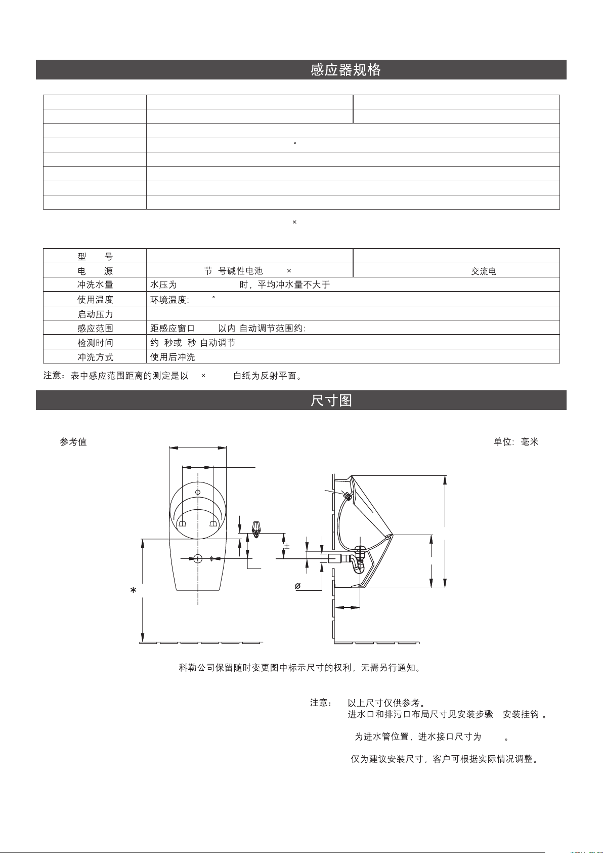
ROUGHING-IN
Reference Value
332
180
G1/2
55
50 ext
145
600
35
80
**
180 5
180
Kohler reserves the right to change marked dimensions without prior notice.
Unit:mm
642
303
Notice: a. The dimensions above are just for reference.
b. The layout dimensions of water and outlet see
inlet
installation step B(Install the hook).
c. ** Indicates the location of inlet pipe, while inlet
connector size is G 1/2.
I
d. * Recommended dimensions for installation only,
please adjust according to actual situation.
1154809-T01-B
a.
b. B( )
c. ** G 1/2
d. *
-2-
Page 3
Notice: To ensure an effective flush performance,
strongly recommended inner diameter of
water supply (including water meter, valve,
etc.) is no less than 25mm, and supplied
water pressure (sensor inlet dynamic
pressure) is 0.18MPa ~0.55MPa.
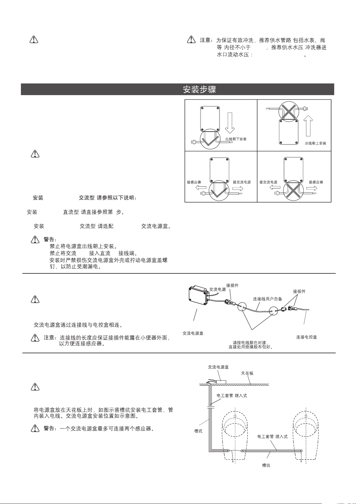
INSTALLATION
1. Please install 16321T-YC05(AC) as below:
Please directly reference to Step 2 when installing 16321T-Y
(DC).
(
) 25mm (
) 0.18MPa ~0.55MPa
A.
Please match 16306T-NA AC power unit when installing
16321T-YC05 (AC).
CAUTION:
a. Outlet of AC power unit upward prohibited.
b. Do not connect 220V AC power supply to DC wiring
terminal.
c. Do not damage the covering of AC power unit or
remove screws to avoid leakage.
1.()
16321T-YC05
16321T-Y
() 2
16321T-YC05
( ) 16306T-NAA.
a.
b. 220V DC
c.
B
. AC power unit connected to electric control box by
connection wire.
Notice:
The length of the connection wire should keep
the connector out of the urinal. It s convenient
'
connect.
Connect to
Sensor
AC
Outlet Downwards
Connect to AC
Power Supply
Connector
Connect to AC
Power Supply
Wire Prepared
By Customer
Outlet Upwards
Connector
Connect to
Sensor
B.
C
. When installing the power unit on the ceiling, please
chisel out a slot and layout bushing according to Fig., and
thread wire through the bushing.
CAUTION:
One AC power unit can supply two
sensors at most.
C.
1154809-T01-B
16306T-NA
AC Power Unit
-3-
Connect with the same color wire,
and protect connect area by insulation tape.
AC Power Unit
Ceiling
Bushing(In-wall)
()
Slot
Bushing
Slot
Connect With
Control Box
(In-wall)
()
Page 4
Notice:
a. Keep the connector away from water.
b. Do not connect the DC output of AC power
unit to AC power supply.
c. Do not connect to power supply while
installing. Connection line is not supplied.
AC connection wire with insulating sleeving
is recommended. Wire of which the
nominal section area of conductor is not
less than 0.5mm is also recommended.
2
DC connection line use wire of which the
nominal section area is not less than
2
0.3mm . It is cut according to acted
installation requirements(The length of cut
wire is recommended less than 10m).
d. The head AC power supply must be
protected with appropriate fuse.
e. Please confirm the AC power supply and
water supply should be shut off before
maintaining the products with AC power
related.
f. Don't install the AC power unit in the free
space behind the urinal to avoid damaging
the AC power unit.
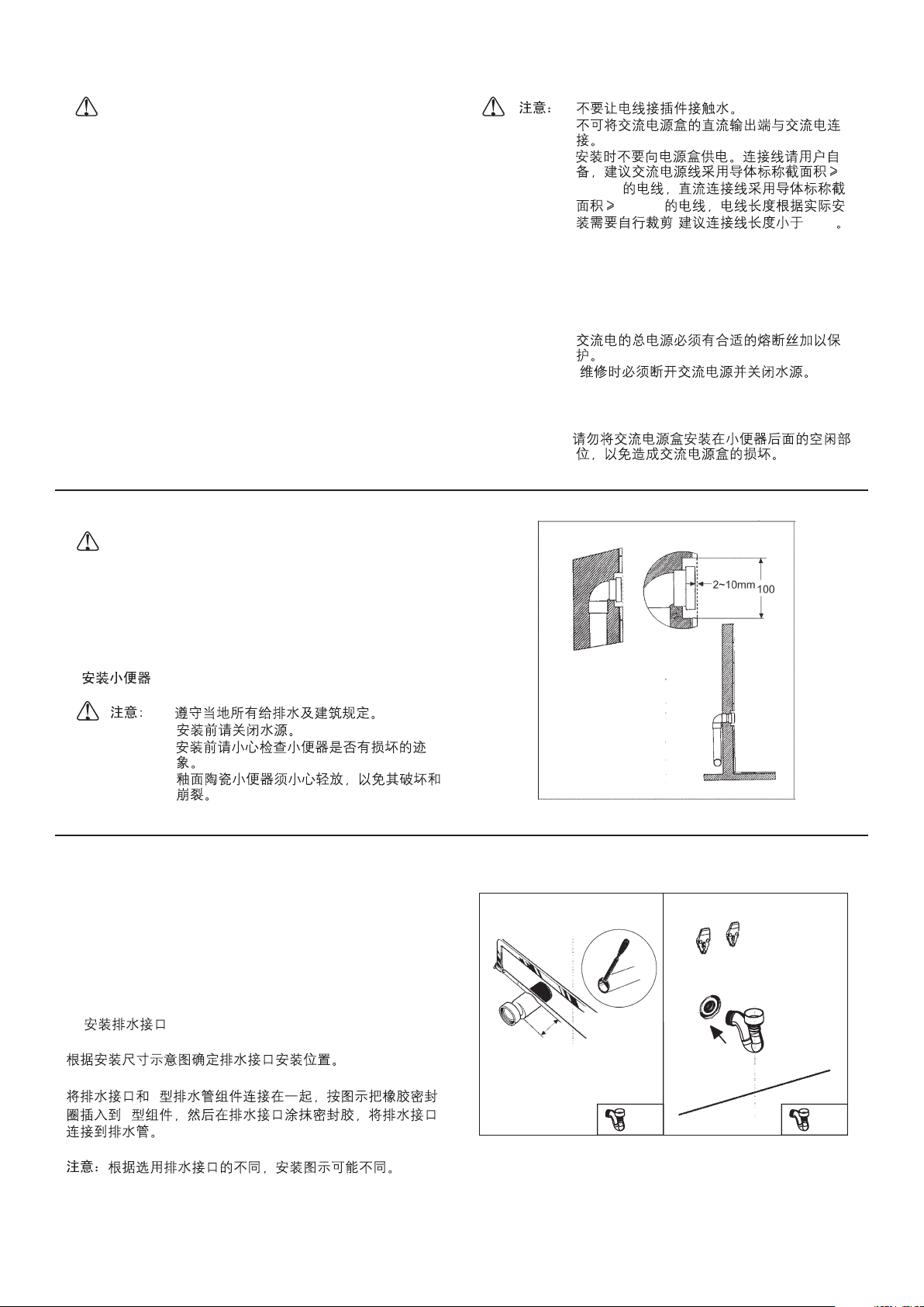
2. Install urinal
Notes: a. Observe all local plumbing and building
codes.
b. Shut off the water supply.
c. Carefully inspect the new fixture for any sign
of damage.
d. Be very careful while hand ling vitreous
china products.
a.
b.
c.
d.
e.
f.
0.5mm
2
0.3mm
2
( 10m)
2.
a.
b.
c.
d.
A.
Install outlet connection
Ascertain the position for outlet connection according to
rough-in dimension.
Connect the outlet connection with the S-trap way. Insert the
gasket into the S-trap way as shown. Apply sealant on outlet
pipe, connect the outlet connection with outlet pipe.
Maybe different for different outlet connections.
Note:
A.
S
S
30
X1 X1
1154809-T01-B
-4-
Page 5

B.B.Install hook
Drill 2 mounting holes on the wall and install hook. Fix hook
on the wall by tightening screws.
180
Supply Pipe
C.C.Install the inlet hose of valve assy.
Take out the bracket of valve assy. Install the limited board (1).
Tighten the tighten screw (2).The inserting depth postion is
as (3).
shown
Connect the inlet pipe with the water supply on the wall.
(1) (2)
(3)
(1)
Limited Board
Bracket of Valve Assy.
Bracket of Valve
(2)
Tighten Screw
(3)
Tighten Screw
1154809-T01-B
-5-
Page 6

D.D.Install urinal
Lift up the urinal, level the installing hole on the back of the
urinal with the hook. Level the outlet connection which is
installed together with the strainer and the gasket on the Strap way. Then insert the outlet connection into the gasket.
(While the outlet connection is inserted, the S-trap way can
be crutched by hard exterded via the gap in the bottom of the
urinal to install it decently.) Then fix the urinal on the hook.
Inlet Hose of Valve Assy
Notice:
a. Avoid the urinal fallen on the floor to
damage the urinal or hurt somebody.
b. Avoid damaging the valve assy and wires.
c. Confirm the wires bare out of urinal base.
d. Set the inlet hose and the inlet hose of
valve assy respectively on the both sides of
the S-trap way before installing urinal.
S
(S
)
a.
b.
c.
d.
S
Inlet Hose
Inlet Hose of Valve Assy
1154809-T01-B
-6-
Page 7

3. Install the bracket assy.
A.
Connect the outlet of valve assy, with the inlet hose.
The way of (DC) installation is as below:
16321T-Y
Take out the battery box from the bracket assy. Loose the
screws of the battery box assy with a screw driver. Put 2
"AAA" size alkline batteries and tighten the battery box's
cover with the screws. Replace the battery box. Connect the
wires with the same color wires.
Note:
Don't mistake the polarity of the batteries and
don't mix the new and used batteries together.
Installing (AC) must connect the AC power unit
16321T-YC05
with control box assy with the same color wires.
3.
A.
16321T-Y
()
27
16321T-YC05
()
Outlet
Inlet Hose
When installing 16321T-YC05,
connect DC output
16321T-YC05
Connector
When installing 16321T-Y,
connect battery box
16321T-Y
Inlet Hose of Valve Assy.
Bracket of Valve
Screw M2.5X20
M2.5X20
B.
Press the two sides spring hooks of bracket of valve assy
close to the center(1). Press the bracket up along the wall
and push it into arc gap of the urinal base(2) until the
spring hooks hangs on the urinal.
Note:
Please carefully handle the stainless steel plate
for its sharp edge will cause possible handcut.
B.
(1)
(2)
Cover of Battery Box
Battery Box
1154809-T01-B
-7-
Urinal
(1)
Spring Hook
(1)
Spring Hook
Bracket of Valve Assy
(2)
Page 8

C.C.Push the bracket away from the wall(3), until the front hook
of the bracket hanging on the urinal.
(3)
D.
Loose the tighten screw. Push the limited board to the
urinal withstanding the wall (4) and then tighten the tighten
screw (5).
Note:
a. When installing the 16321T-YC05(AC), do
not connect to power supply until finish
installation.
b. Taking out the bracket just need to athwort
the way of installations.
Front Hook
D.
(5)
(4) (5)
a. ( )
16321T-YC05
220V
b.
(4)
(5)
(3)
Limited Board
Tighten Screw
1154809-T01-B
-8-
Page 9

USER S GUIDE
,
,
Don t use this system until the power is on for 10
minutes.
The sensing distance will be adjusted and the system
will not work during this time.
Working Status
Before powering the system on, chear the unwanted objects
in front of the sensor window lest shortening the sensing
distance.
Sensing Distance
10
During the first 10 minutes, when powered on, the system is
in the phase of automatic regulation, and no operation is
required.
Replacement of Batteries(Only for )
When out of power, the indicator will flash every 2 seconds
and the sensor will not work until new batteries are supplied.
When replacing batteries, open the cover of battery box and
put in new batteries.
()
16321T-Y
2
16321T-Y
Deodorizing Flushing
The urinal will take a flush automatically when it’s used 3 or 4
times in 2 minutes.
10
Indicator
2 3-4
1154809-T01-B
-9-
Page 10

Manual Flushing
Approach the supplied special magnetic stick (flushing control
stick) to the sensor lens. The system is now at a manual
status and the indicator will flash every 1 seconds. Approach
the flushing control stick to the sensor lens once, it ll flush
once. This status will last for about 8 minutes until turns to the
normal working status.
,
Notice:
If the flushing control stick keeps near to the
sensing window for 30 seconds, the manual
status will be terminated automatically and
reassume the normal working status.
()
1
8
30
Used in places of low water pressure
If the flushing amount is limited due to low water pressure,
you can set a long time washing with flushing control stick.
Operate as follows: Ten minutes after power-on, you can
switch between two wash times by putting the flushing control
stick near the right side of sensing window. There will be a 2second rinse after you complete the setting. If you need to
reset the wash time, you must cut off the power and restart
the sensor and 10 minutes later, you're able to switch wash
time with flushing control stick.
,
Flushing Control Stick
Note:
Under the normal water pressure, it is not
recommended to use this flushing method in
order to prevent excessive flushing and water
spills out.
10
()
2
10
1154809-T01-B
-10-
Page 11

MAINTENANCE
Urinal Repair
When repairing, you don t have to dismount the sensor.
'
Cover the sensing window with tape and work with ease.
,
: Don t use very adhesive tape in case the scar
Notice
will be hard to remove.
Clean the Filter Screen
If the flushing volume reclines sharply after installation or
used for a long time with no cause from water pressure, the
filter may need a wash. Please operate as following steps:
Remove the bracket of valve assy. Loose the inlet hose firstly.
Loose the inlet hose of valve assy. and then take out the filter.
Clean it with a brush and reinstall.
Caution:
a. Turn off the water supply before cleaning
the filter, also power off when used the AC
power supply.
b. Avoid damaging or losing the filter during
cleaning.
Inlet Hose
When installing 16321T-YC05,
connect DC output
16321T-YC05
Connector
When installing 16321T-Y,
connect battery box
16321T-Y
Inlet Hose of Valve Assy.
a.
b.
Care & Clean
Keep the sensing window clean. Wipe with soft cloth and mild
cleaner.
Notice:
a. Do not use dust-removing powder, abrasive powder
or cleaner containing oil, acid or alkaline ingredient.
b. Do not spray air-refresher, disinfector, or other
deodorizing, cleaning solvent directly into the
sensing window.
c. Keep wire away from water.
d. Don t attack the sensor window.
'
Filter
Bracket of Valve
a.
b.
c.
d.
1154809-T01-B
-11-
Page 12

TROUBLESHOOTING
Please make following checks before repair:
Symptoms
No flushing
(Indicator not flashing).
No flushing or poor
flushing while the indicator
can flash.
Keep flushing indicator not
flashing.
Battery indicating light
keeps flashing and no
flushing.
If the trouble remains after above-mentioned actions are taken, please contact with us via distributor.
()
1. No power or mistake connected.
2. There is an object within the sensing distance.
3. The sensing window needs cleaning.
1. Still in the waiting status.
2. Adjusting bolt not fully open
3. Low water pressure.
4. Filter is obstructed.
5. The connector is not connected well.
1. The small hole of valve core is blocked.
2. The filter of valve core is blocked.
Out of electricity.
(Only for 16321T-Y)
1.
2.
3.
1.
2.
3.
4.
5.
1.
2.
Probable causes
Corrective actions
1. Check the power connect.
2. Remove the object .
3. Clean the window.
1. Wait for 10 minutes.
2. Open the adjusting bolt.
3. Improve water supply.
4. Clean the filter.
5. Check the connector.
1. Clean the small hole of valve core with
thin steel wire.
2. Wash the filter of valve core with a brush.
Replace batteries.
1.
2.
3.
1. 10
2.
3.
4.
5.
1.
2.
()16321T-Y
1154809-T01-B
-12-
Page 13

IMPORTANT CONSUMER INFORMATION
Consumer Responsibilities
1. Do not attack the sensor.
2. Do not directly flush the sensor with water. The sensor is
an electronic instrument.
3. Do not let sunlight or other light source enter or be
reflected into Sensor Window.
4. Do not hang on the opposite wall any reflective items or
install light/electronic sensor such as toilet flushing sensor.
5. Do not make Sensor Window near strong ultraviolet or
electromagnetic field.
6. Keep the sensor window clean.
The sensor cover can be cleaned by soft rag with neutral
liquid detergent.
Do not use eradicator, abrasive powder or oil, acid or
alkali liquid detergent.
Do not spray air freshener, disinfectant or other kinds of
odious removing, cleaning organic liquid to the sensor
directly.
7. Urinal is designed for use with potable water. Avoid water
that includes a lot of contaminants or acid/alkali water and
impure water.
8. When AC power unit is connected to 220V AC power
supply, corresponding protective measures should be
taken.
1.
2.
3.
4.
()
5.
6.
7.
8. 220V
9. Please confirm no water penetration at the connection
area of AC wire, and the connection area is not easy to
be affected by damp.
10. Don t connect power unit to AC power supply until the
11. The head AC power supply must be protected with
12. Please confirm the AC power supply and water supply
13. All electrical connection must be compliance with related
14. All installation staff should be well familiar with
'
sensor installation is finished.
appropriate fuse.
should be shut off before maintaining the products with
AC power related.
regulation and codes.
installation instruction.
WARNING
something else into the urinal.
WARNING: Risk of product damage.
Do not throw into the urinal what is easy to block it,
such as newspaper, paper pilch.
Do not bump the vitreous china with great force to
prevent it from damaging and leaking.
Do not use the product in the water below 0 C.
Never spit phlegm and throw stub or
o
9.
10.
11.
12.
13.
14.
o
0C
CAUTION: Please do not use hard materials (like
scouring pad) to clean product surface, especially the
product logo.
1154809-T01-B
-13-
 Loading...