

Page 1

Installation Guide
Remote Installation Kit
Français, page “Français-1”
Español, página “Español-1”
1037564-2-E
Page 2
Important Information
WARNING: When using electrical products, basic precautions should always be followed,
including the following:
DANGER: Risk of electric shock. To reduce the risk of electrical shock, connect only to circuits
protected by a Ground-Fault Circuit-Interrupter (GFCI) or Residual Current Device (RCD).
WARNING: Risk of electric shock. A qualified electrician should make all electrical connections.
WARNING: Risk of electric shock. Disconnect power before servicing.
NOTICE: Follow all local plumbing and electrical codes.
Building materials and wiring should be routed away from the blower body and other heat-producing
components of the unit.
Install to permit access for servicing.
Product Information
Electrical Requirements
NOTE: If the supply cord is damaged, it must be replaced by the manufacturer, its service agent, or
similarly qualified persons in order to avoid a hazard.
The installation must have a Class A Ground-Fault Circuit-Interrupter (GFCI) or Residual Current Device
(RCD). The GFCI or RCD protects against line-to-ground shock hazard. Use a 120 V, 15 A, 50/60 Hz
dedicated service for the bath with airjets.
An equipment grounding terminal is provided in the field wiring compartment. To reduce the risk of electric
shock, this terminal must be connected to the grounding means provided in the electric supply panel with a
conductor equivalent in size to the circuit conductors supplying this equipment.
The electrical rating of the bath is printed on a label near the blower motor. You can also find the electrical
requirements from the installation guide packed with the bath and the specification sheet found on the
product page at www.kohler.com.
Product Notices
WARNING: Risk of personal injury or property damage. Unauthorized modification may cause
unsafe operation or effect performance of the bath with airjets. Do not relocate the blower motor,
or make other modifications to the bath system in the absence of kit or other published instructions,
as this could adversely affect the performance and safe operation of the product. Kohler Co. shall
not be liable under its warranty or otherwise for personal injury or damage caused by any such
unauthorized modification. Refer to the ″Before You Begin″ section for blower motor relocation
requirements, recommendations, and section coverage information.
NOTICE: Keep the area around the blower motor clean and free of debris. Ensure that the area around
the blower motor is free of sawdust, insulation, dirt, or other small loose debris. Such material could plug
the blower motor air ducts and reduce the air flow through the blower.
Connections and Service Access
NOTICE: Provide unrestricted service access to the blower motor. You must provide access for servicing
the blower motor and controls. The access must be located immediately next to the blower motor. Study
the roughing-in information.
If the blower motor is installed in an enclosed area, an access panel is required at the blower motor. This
panel should be 18″ (457 mm) wide and 14″ (356 mm) high minimum.
1037564-2-E 2 Kohler Co.
Page 3

Tools and Materials
•
Flat blade screwdriver
•
Drill and bits to install the blower mounting fasteners
•
1-1/2″ PVC or other pipe with fittings, unions, PVC cement (or equivalent fastening method), and
support clips (as required)
•
Four fasteners (such as flathead wood screws or concrete anchors) to mount the blower motor
•
Cable ties/support clips to support the keypad cable
Kohler Co. 3 1037564-2-E
Page 4
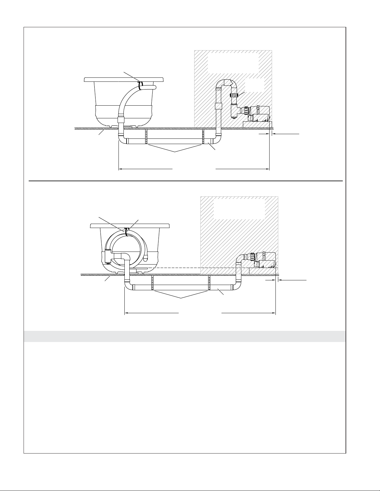
With Check Valve
Subfloor
Do not remove
strap
.
Do not remove
strap
.
Do not uncoil
the hose
Support Straps
15' (4.6 m) Max
Without Check Valve
.
30 Cubic Feet
(0.8 Cubic Meters)
Min Air Space
Check
Valve
1"
(25 mm)
Min
1-1/2"
Rigid PVC
30 Cubic Feet
(0.8 Cubic Meters)
Min Air Space
1"
(25 mm)
Min
Subfloor
Support Straps
15' (4.6 m) Max
1-1/2"
Rigid PVC
Before You Begin
NOTICE: It is not necessary to relocate the blower motor. The option is provided for particular
installations where a remote location is practical.
NOTICE: For blower with check valve: Relocate the blower motor and check valve together. Do not
relocate one without the other.
NOTICE: DO NOT relocate the control unit. The control unit must remain with the bath.
NOTE: Refer to the Installation Guide packed with the bath for preliminary steps and considerations for
installation of the bath.
NOTE: Your product and piping my appear different than the layout shown above. The installation
guidelines and procedures remain the same.
1037564-2-E 4 Kohler Co.
Page 5

Before You Begin (cont.)
Relocate the blower motor as close to the bath as possible to maximize bath performance. The
blower motor must be located within 15’ (4.6 m) of the bath, with no more than six direction
changes in piping.
If the blower motor is wired to a junction box (Canada units only), the junction box and blower
must be moved together.
The blower motor must be oriented horizontally, and installed to a support block that is the same
height as the original mounted location relative to the bath, or 1-1/2″ (38 mm) above the floor.
For blower with check valve: At the new location, the check valve must be no lower than 24″ (610
mm) below the rim of the bath. The check valve must be within 12″ (305 mm) of the blower motor.
The check valve must be oriented vertically with the flow arrow pointing up.
The blower motor must have adequate ventilation for cooling and airflow. Do not install the blower
motor closer than 1” (25 mm) from the wall or other objects. Provide approximately 30 cubic feet
(0.8 cubic meters) of minimum air space for cooling.
Use 1-1/2″ PVC or equivalent piping.
The piping installation must meet the requirements of local plumbing or building codes. Ensure that
the installation does not reduce the fire rating of any walls.
Piping must be supported at intervals along the length in accordance with local codes.
Ensure that the blower motor location is clean and free of dust or debris.
If appropriate, install an additional access panel for blower motor maintenance.
In accordance with local codes, the keypad cable must be supported by cable ties or support clips at
intervals along the length of the bath. The cable must not rest on wet surfaces or floors that are
subject to flooding.
All material needed for the relocation must be supplied by the installer. This includes everything
below the subfloor up to the couplers included in the kit.
1. Prepare Site
Prepare the site for the bath installation and blower motor installation. Refer to the installation
instructions packed with your bath.
Install the required access panel to service the blower motor.
Prepare routing paths for the PVC piping and the keypad cable. Follow all applicable building, fire,
plumbing, and electrical codes.
Kohler Co. 5 1037564-2-E
Page 6

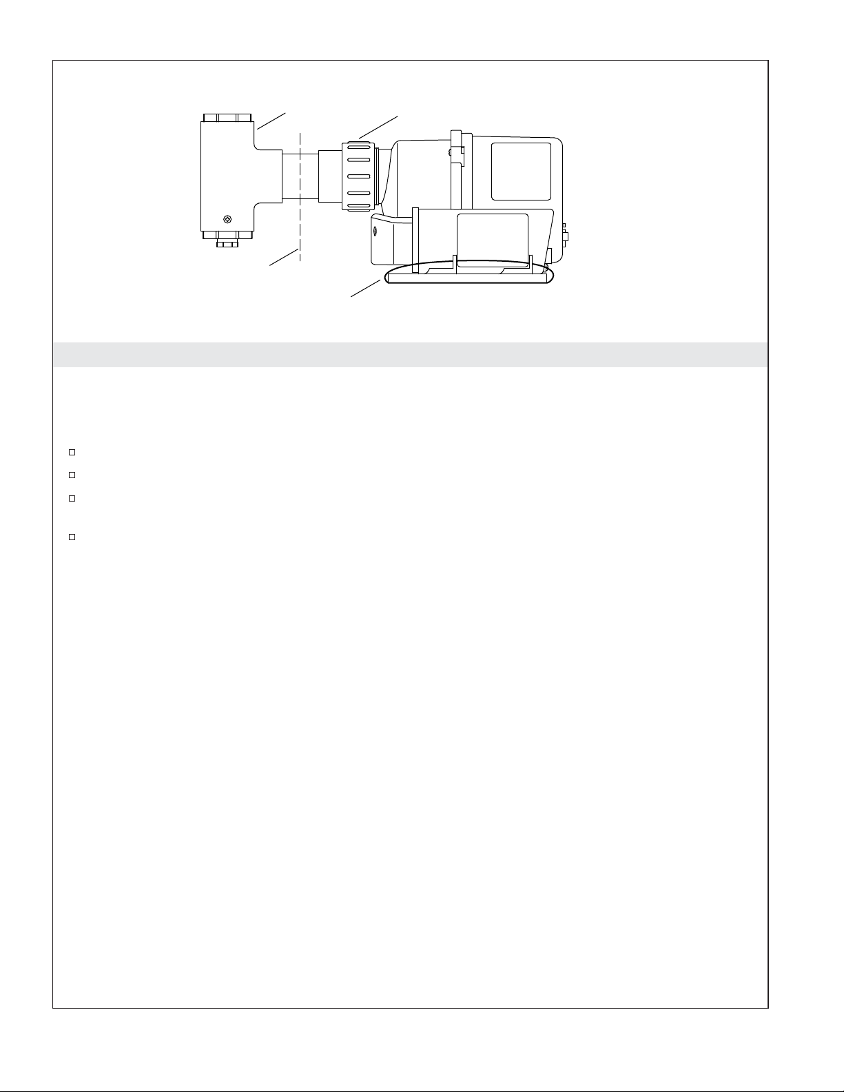
Tee
Cut here.
Strap
Union Nut
2. Disconnect
For Blower Motor without Check Valve Only
IMPORTANT! Do not cut, remove, or uncoil the coiled piping if attached to the bath.
Cut the middle of the 1-1/2″ PVC pipe located between the tee and the union nut.
Disconnect and remove the cable connecting the blower motor and the user interface.
Cut the straps holding the blower motor to the support board on the bath.
Prepare, install, and secure the bath. Refer to the installation instructions packed with your bath.
1037564-2-E 6 Kohler Co.
Page 7
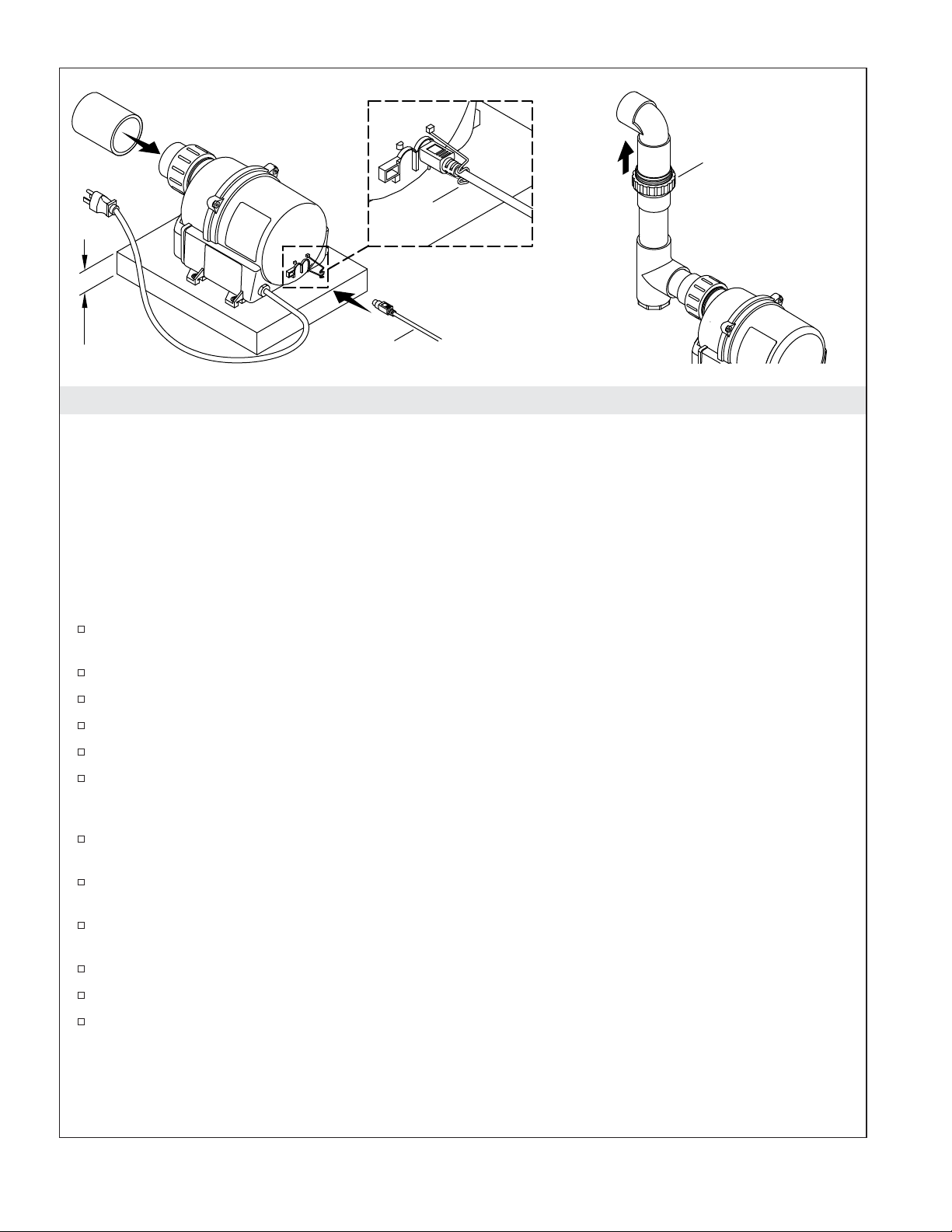
Check Valve
Retainer
Clip
1-1/2
(38 mm)
Cable
3. Reconnect
NOTE: The blower motor must be located within 15’ (4.6 m) of the bath, with no more than six direction
changes in piping.
NOTE: If the blower motor is wired to a junction box (Canada units only), the junction box and blower
must be moved together.
NOTE: The blower motor must be oriented horizontally, and installed to a support block that is the same
height as the original mounted location relative to the bath, or 1-1/2″ (38 mm) above the floor.
NOTE: Refer to the ″Before You Begin″ section for other detailed requirements for the blower motor
relocation.
At the new blower motor location, install a minimum 1-1/2″ (38 mm) high block (not supplied) for
the blower motor support.
Use the blower motor as a template to mark the location of the four mounting bolts or screws.
Drill four pilot holes for the blower motor mounting screws.
Fasten the blower motor to the support board.
Route PVC or other 1-1/2″ piping (not supplied) between the bath and the blower motor location.
For blower with check valve: Install the check valve at the blower motor location. The check valve
must be oriented vertically. Confirm the check valve is oriented with the flow arrow pointing away
from the blower motor, and that it is located no lower than 24″ (610 mm) below the bath rim.
For blower without check valve: Connect each previously cut end of the PVC with the provided
1-1/2″ couplings.
Route the provided cable from the new blower motor location to the bath. Use cable ties or other
support clips (not supplied) to support the cable.
Connect the cable to the blower motor. The cable connector at the blower should be oriented with
the flat side facing up.
Use the provided retaining clip to prevent accidental cable disconnection.
Connect the cable to the user interface.
Ensure that any wall holes are properly sealed as required by local building or fire codes.
Kohler Co. 7 1037564-2-E
Page 8
4. Make Electrical Connections
WARNING: Risk of electric shock. To reduce the risk of electric shock, connect the control to a
properly grounded Ground-Fault Circuit-Interrupter (GFCI) or Residual Current Device (RCD). This
will provide additional protection against line-to-ground shock hazard.
Make electrical connections according to the Installation Guide packed with the bath.
Complete the bath installation according to the Installation Guide packed with the bath.
1037564-2-E 8 Kohler Co.
Page 9

Guide d’installation
Kit d’installation à distance
Informations importantes
AVERTISSEMENT: Lors de l’utilisation de produits électriques, toujours observer les
précautions de base, notamment:
DANGER: Risque de choc électrique. Afin de réduire les risques d’électrocution, connecter
seulement à des circuits protégés par un disjoncteur de fuite de terre (GFCI) ou à un dispositif à
courant résiduel (RCD).
AVERTISSEMENT: Risque de choc électrique. Un électricien qualifié doit effectuer toutes les
connexions électriques.
AVERTISSEMENT: Risque de choc électrique. Déconnecter l’alimentation électrique avant
d’effectuer un entretien.
AVIS: Respecter tous les codes de plomberie et électriques locaux.
Les matériaux de construction et le câblage doivent être acheminés loin du souffleur et des autres
composants qui dégagent de la chaleur de l’appareil.
Installer de façon à permettre l’accès pour l’entretien.
Information sur le produit
Installations électriques requises
REMARQUE: Si le cordon d’alimentation est endommagé, il doit être remplacé par le fabricant, son
représentant technique ou un personnel ayant les mêmes qualifications, afin d’éviter tout danger.
L’installation doit comprendre un disjoncteur de fuite de terre (GFCI) ou un dispositif à courant résiduel
(RCD) de classe A. Le GFCI ou le RCD protège contre les dangers d’électrocution par une tension
phase-terre. Utiliser une alimentation de 120 V, 15 A, 50/60 Hz dédiée à la baignoire avec jets d’air.
Une borne de mise à la terre est incluse dans le boîtier du câblage sur place. Pour réduire les risques de choc
électrique, cette borne doit être raccordée à un dispositif de mise à la terre fourni dans le panneau
d’alimentation électrique, avec un conducteur ayant le même calibre que celui des conducteurs du circuit qui
alimente cet équipement.
Le régime électrique nominal de la baignoire est imprimé sur une étiquette placée à proximité du moteur du
souffleur. Les conditions électriques requises sont également indiquées dans le guide d’installation
accompagnant la baignoire et la fiche de spécifications se trouvant sur la page du produit au
www.kohler.com.
Notices du produit
AVERTISSEMENT: Risque de blessures ou d’endommagement matériel. Des modifications non
approuvées pourraient provoquer un fonctionnement dangereux ou affecter la performance de la
baignoire avec jets d’air. Ne pas changer l’emplacement du moteur du souffleur et ne pas effectuer
d’autres modifications sur le système de baignoire sans le kit ou sans autres instructions publiées,
vu que ceci pourrait perturber la performance et ne plus assurer le fonctionnement sans danger du
produit. Kohler Co. décline toute responsabilité sous sa garantie et pour toutes blessures ou tous
dommages causés par de telles modifications non autorisées. Se référer à la section ″Avant de
commencer″ pour les conditions requises pour le déplacement du moteur du souffleur, aux
Kohler Co. Français-1 1037564-2-E
Page 10

Information sur le produit (cont.)
recommandations, et à l’information de couverture de la section.
AVIS: Garder l’espace autour du moteur du souffleur propre et exempt de débris. S’assurer que l’espace
autour du moteur du souffleur est exempt de sciure, de matériau isolant, de saleté, ou d’autres petits
débris volatiles. De tels matériaux pourraient boucher les conduits d’air du moteur du souffleur et réduire
le débit d’air à travers le souffleur.
Connexions et accès pour l’entretien
AVIS: Fournir un accès libre au moteur du souffleur. Un accès doit être prévu pour l’entretien du moteur
du souffleur et des commandes. L’accès doit se trouver juste à côté du moteur du souffleur. Étude du plan
de raccordement.
Si le moteur du souffleur est installé dans un espace fermé, un panneau d’accès au moteur du souffleur est
requis. Ce panneau doit avoir une largeur de 18″ (457 mm) et une hauteur de 14″ (356 mm) minimum.
Outils et matériel
•
Tournevis à lame plate
•
Perceuse et mèches pour installer les dispositifs de fixation du souffleur.
•
PVC 1-1/2″ ou autre tube avec raccords, unions, ciment PVC (ou méthode de fixation équivalente)
et clips de support (tel que requis)
•
Quatre dispositifs d’attache (comme des vis à bois à tête plate ou des chevilles d’ancrage en béton)
pour monter le moteur du souffleur
•
Attache-câbles/clips de support pour soutenir le câble du clavier
1037564-2-E Français-2 Kohler Co.
Page 11

Avec clapet de non-retour
Sous-plancher
Ne pas retirer
la sangle.
Ne pas retirer
la sangle.
Sangles de support
15' (4,6 m) Max
Sans clapet de non-retour
Ne pas dérouler
le tuyau.
Espace d'air min
30 pieds cubes
(0,8 mètre cube)
Clapet de
non-retour
1"
(25 mm)
Min
PVC rigide
1-1/2"
Espace d'air min
30 pieds cubes
(0,8 mètre cube)
1"
(25 mm)
Min
Sous-plancher
Sangles de support
15' (4,6 m) Max
PVC rigide
1-1/2"
Avant de commencer
AVIS: Il n’est pas nécessaire de repositionner le moteur du souffleur. L’option est fournie pour des
installations particulières où un emplacement à distance est pratique.
AVIS: Pour souffleur avec clapet de non-retour: Repositionner le moteur souffleur et le clapet de
non-retour ensemble. Ne pas déplacer l’un sans l’autre.
AVIS: NE PAS repositionner le module de commande. Le module de commande doit rester avec la
baignoire.
REMARQUE: Se reporter au Guide d’installation accompagnant la baignoire pour des étapes
préliminaires et des considérations pour l’installation de la baignoire.
REMARQUE: Le produit et la tuyauterie pourraient être différents de la disposition illustrée ci-dessus.
Les directives et les procédures d’installation restent les mêmes.
Kohler Co. Français-3 1037564-2-E
Page 12

Avant de commencer (cont.)
Repositionner le moteur du souffleur aussi près que possible de la baignoire, afin de maximiser la
performance de la baignoire. Le moteur du souffleur doit être compris dans un rayon de 15’ (4,6 m)
de la baignoire, avec six changements de direction maximum dans la tuyauterie.
Si le moteur du souffleur est câblé avec une boîte de connexion (modules canadiens uniquement), la
boîte de jonction et le souffleur doivent être déplacés ensemble.
Le moteur du souffleur doit être orienté à l’horizontale, et il doit être installé sur un bloc de support,
qui est à la même hauteur que celle de l’emplacement de montage original par rapport à la
baignoire, ou à à 1-1/2″ (38 mm) au-dessus du plancher.
Pour souffleur avec clapet de non-retour: Au nouvel emplacement, le clapet de non-retour ne doit
pas être inférieur à 24″ (610 mm) au-dessous du rebord de la baignoire. Le clapet de non-retour doit
se trouver dans un espace de 12″ (305 mm) du moteur du souffleur. Le clapet de non-retour doit être
orienté verticalement avec la flèche du débit dirigée vers le haut.
Le moteur du souffleur doit avoir une ventilation adéquate pour le refroidissement et le débit d’air.
Ne pas installer le moteur du souffleur à une distance plus proche de 1” (25 mm) du mur ou
d’autres objets. Fournir 30 pieds cubes (0,8 mètre cube) environ d’espace d’air minimum pour le
refroidissement.
Utiliser un PVC de 1-1/2″ ou une tuyauterie équivalente.
L’installation de la tuyauterie doit être conforme aux codes de plomberie et de bâtiment locaux.
S’assurer que l’installation ne réduit pas le classement au feu des murs.
La tuyauterie doit être supportée à des intervalles sur la longueur conformément aux codes locaux.
S’assurer que l’espace du moteur du souffleur est propre et exempt de poussière ou de débris.
Si approprié, installer un panneau d’accès supplémentaire pour permettre un entretien du moteur
du souffleur.
Selon les codes locaux, le câble du clavier doit être supporté par des attaches de câble ou des clips
de support à des intervalles le long de la longueur de la baignoire. Le câble ne doit pas reposer sur
des surfaces ou sur des planchers mouillés qui sont susceptibles aux inondations.
Tous les matériaux nécessaires au déplacement doivent être fournis par l’installateur. Ceci inclut tout
ce qui est sous le sous-plancher jusqu’aux coupleurs inclus dans le kit.
1. Préparer le site
Préparer le site pour l’installation de la baignoire et l’installation du moteur du souffleur. Se référer
aux instructions d’installation accompagnant la baignoire.
Installer le panneau d’accès requis pour l’entretien du moteur du souffleur.
Préparer les voies d’acheminement pour la tuyauterie PVC et le câble du clavier. Respecter tous les
codes s’appliquant à la construction, à la prévention des incendies, à la plomberie, et à l’électricité.
1037564-2-E Français-4 Kohler Co.
Page 13
Té
Couper ici.
Sangle
Écrou de raccordement
2. Déconnecter
Pour moteur de souffleur sans clapet de non-retour uniquement
IMPORTANT! Ne pas couper, retirer ou dérouler la tuyauterie enroulée si elle est attachée sur la
baignoire.
Couper le milieu du tuyau PVC de 1-1/2″ PVC se trouvant entre le té et l’écrou de raccord.
Déconnecter et retirer le câble qui connecte le moteur du souffleur et l’interface utilisateur.
Couper les sangles qui maintiennent le moteur du souffleur sur la planche de support sur la
baignoire.
Préparer, installer et fixer la baignoire en place. Se référer aux instructions d’installation
accompagnant la baignoire.
Kohler Co. Français-5 1037564-2-E
Page 14

Clapet de non-retour
Clip de
retenue
1-1/2
(38 mm)
Câble
3. Reconnecter
REMARQUE: Le moteur du souffleur doit être compris dans un rayon de 15’ (4,6 m) de la baignoire, avec
six changements de direction maximum dans la tuyauterie.
REMARQUE: Si le moteur du souffleur est câblé avec une boîte de connexion (modules canadiens
uniquement), la boîte de jonction et le souffleur doivent être déplacés ensemble.
REMARQUE: Le moteur du souffleur doit être orienté à l’horizontale, et il doit être installé sur un bloc de
support, qui est à la même hauteur que celle de l’emplacement de montage original par rapport à la
baignoire, ou à à 1-1/2″ (38 mm) au-dessus du plancher.
REMARQUE: Se référer à la section ″Avant de commencer″ pour les autres conditions requises pour le
déplacement du moteur du souffleur.
Au nouvel emplacement du moteur du souffleur, installer un bloc (non fourni) d’une hauteur
minimum de 1-1/2″ (38 mm) pour supporter le moteur du souffleur.
Utiliser le moteur du souffleur comme gabarit afin de marquer l’emplacement des quatre boulons de
fixation ou vis.
Percer quatre trous pilotes pour les vis de fixation du moteur du souffleur.
Fixer le moteur du souffleur en place sur la planche de support.
Acheminer la tuyauterie ou d’autres tuyaux de 1-1/2″ (non fournis) entre l’emplacement de la
baignoire et le moteur du souffleur.
Pour souffleur avec clapet de non-retour: Installer le clapet de non-retour à l’emplacement du
moteur du souffleur. Le clapet de non-retour doit être orienté verticalement. S’assurer que le clapet
de non-retour est orienté avec la flèche de débit dirigée dans le sens opposé du moteur du souffleur
et qu’il n’est pas positionné à une distance inférieure à 24″ (610 mm) au-dessous du rebord de la
baignoire.
Pour souffleur sans clapet de non-retour: Connecter chaque extrémité du tuyau PCV coupée
auparavant aux raccords de 1-1/2″ fournis.
Acheminer le câble fourni entre l’emplacement du nouveau moteur du souffleur et la baignoire.
Utiliser les attache-câbles ou d’autres clips de support (non fournis) pour supporter le câble.
Connecter le câble au moteur du souffleur. Le connecteur du câble au niveau du souffleur doit être
orienté avec le côté plat tourné vers le haut.
Utiliser l’étrier fourni pour empêcher une déconnexion accidentelle du câble.
Connecter le câble à l’interface utilisateur.
1037564-2-E Français-6 Kohler Co.
Page 15

Reconnecter (cont.)
S’assurer que les trous de mur sont scellés correctement tel que requis par les codes de bâtiment ou
de prévention des incendies locaux.
4. Effectuer les connexions électriques
AVERTISSEMENT: Risque de choc électrique. Afin de réduire les risques de choc électrique,
connecter la commande à un disjoncteur de fuite de terre (GFCI) ou à un dispositif à courant
résiduel (RCD) mis à la terre de manière adéquate. Ceci fournira une mesure de protection
supplémentaire contre le risque d’électrocution par tension phase-terre.
Établir les connexions électriques selon le guide d’installation accompagnant la baignoire.
Terminer l’installation de la baignoire selon le guide d’installation accompagnant la baignoire.
Kohler Co. Français-7 1037564-2-E
Page 16

Guía de instalación
Kit para instalación remota
Información importante
ADVERTENCIA: Al usar aparatos eléctricos siempre cumpla las precauciones básicas, incluidas
las siguientes:
PELIGRO: Riesgo de sacudidas eléctricas. Para reducir el riesgo de una sacudida eléctrica, conecte
la bomba a un tomacorriente correctamente conectado a tierra protegido por un interruptor de
circuito con pérdida a tierra (GFCI) o un dispositivo de corriente residual (RCD).
ADVERTENCIA: Riesgo de sacudidas eléctricas. Un electricista calificado debe hacer todas las
conexiones eléctricas.
ADVERTENCIA: Riesgo de sacudidas eléctricas. Desconecte el suministro eléctrico antes de dar
servicio.
AVISO: Cumpla todos los códigos locales de electricidad y de plomería.
El material de construcción y el cableado se deben colocar lejos del cuerpo del motor soplador y de otros
componentes de la unidad que producen calor.
Instale de manera que quede acceso para dar servicio.
Información sobre el producto
Requisitos eléctricos
NOTA: Si el cable de alimentación eléctrica está dañado debe ser reemplazado por el fabricante, por su
agente de servicio o por personas igualmente calificadas para así evitar peligro.
La instalación debe contar con un interruptor de circuito con pérdida a tierra (GFCI) o con un dispositivo de
corriente residual (RCD) ambos de clase A. El GFCI o RCD protege contra el peligro de sacudida eléctrica de
línea a tierra. Use un servicio dedicado de 120 V, 15 A, 50/60 Hz para la bañera con jets de aire.
El compartimiento de cables tiene un terminal de conexión a tierra para el equipo. Para reducir el riesgo de
sacudidas eléctricas, este terminal se debe conectar a la conexión a tierra provista en el panel de suministro
eléctrico con un conductor del tamaño equivalente al de los conductores del circuito que alimentan este
equipo.
La capacidad nominal eléctrica de la bañera está impresa en una etiqueta cerca del motor soplador. También
se pueden encontrar los requisitos eléctricos en la guía de instalación que se incluye con la bañera y en la
hoja de especificaciones en la página del producto en www.kohler.com.
Avisos sobre el producto
ADVERTENCIA: Riesgo de lesiones personales o daños a la propiedad. Las modificaciones no
autorizadas pueden causar funcionamiento peligroso o afectar el rendimiento de la bañera con
jets de aire. No cambie la ubicación del motor soplador, ni haga ninguna otra modificación al
sistema de la bañera, si no dispone de un kit o de otras instrucciones publicadas, ya que esto
podría afectar negativamente el rendimiento y el funcionamiento seguro del producto. Kohler Co.
no será responsable bajo su garantía o de ninguna otra forma, de lesiones personales o daños
provocados por modificaciones no autorizadas. En la sección ″Antes de comenzar″, consulte las
recomendaciones y los requisitos de reubicación del motor soplador, así como información general
de la sección.
Kohler Co. Español-1 1037564-2-E
Page 17

Información sobre el producto (cont.)
AVISO: Mantenga limpia y libre de suciedad el área alrededor del motor soplador. Asegúrese de que en
el área alrededor del motor soplador no haya aserrín, material aislante, tierra u otras partículas sueltas
pequeñas. Dichos materiales podrían tapar los conductos de aire del motor soplador y reducir el flujo de
aire a través del soplador.
Acceso de servicio y a las conexiones
AVISO: Deje acceso sin restricciones para dar servicio al motor soplador. Usted debe dejar acceso para
dar servicio al motor soplador y a los controles. El acceso debe estar justo al lado del motor soplador.
Revise la información de instalación.
Si el motor soplador ha sido instalado en un área cerrada, es necesario instalar un panel de acceso al motor
soplador. Este panel debe tener un mínimo de 18″ (457 mm) de ancho y 14″ (356 mm) de alto.
Herramientas y materiales
•
Destornillador de hoja plana
•
Taladro y brocas para instalar los herrajes de montaje del soplador
•
Tubo de 1-1/2″ de PVC o de otro tipo con conexiones, uniones, cemento para PVC (o método de
fijación equivalente) y clips de soporte (según se requiera)
•
Cuatro sujetadores (como tornillos de cabeza plana para madera o anclajes para concreto) para
instalar el motor soplador
•
Sujetacables/clips de soporte para fijar el cable del teclado
Kohler Co. Español-2 1037564-2-E
Page 18

Con válvula de retención
Subpiso
No retire
la correa.
No retire
la correa.
Correas de soporte
15' (4,6 m) máx.
Sin válvula de retención
No desenrolle
la manguera.
Espacio mín. de aire
30 pies cúbicos
(0,8 metros cúbicos)
Válvula
de retención
1"
(25 mm)
mín.
PVC rígido
de 1-1/2"
Espacio mín. de aire
30 pies cúbicos
(0,8 metros cúbicos)
1”
(25 mm)
mín.
Subpiso
Correas de soporte
15' (4,6 m) máx.
PVC rígido
de 1-1/2"
Antes de comenzar
AVISO: No es necesario cambiar de ubicación el motor soplador. La opción se incluye para instalaciones
en las que una ubicación remota sea práctica.
AVISO: En sopladores con válvula de retención: Cambie de lugar juntos el motor soplador y la válvula
de retención. No cambie de lugar uno sin el otro.
AVISO: NO cambie de lugar la unidad de control. La unidad de control debe permanecer con la bañera.
NOTA: En la guía de instalación que se adjunta con la bañera consulte los pasos y las consideraciones
preliminares para la instalación de la bañera.
NOTA: Es posible que su producto y las tuberías se vean distintas de la distribución que se muestra
arriba. Las guías y los procedimientos de instalación son los mismos.
1037564-2-E Español-3 Kohler Co.
Page 19

Antes de comenzar (cont.)
Cambiar de ubicación el motor soplador lo más cerca a la bañera como sea posible para obtener el
máximo rendimiento en la bañera. El motor soplador debe ubicarse a menos de 15’ (4,6 m) de la
bañera, sin más de seis cambios de dirección en la tubería.
Si el motor soplador se cablea a una caja de empalmes (solo unidades para Canadá), la caja de
empalmes y el soplador deben ser retirados juntos.
El motor soplador debe orientarse horizontalmente, y debe instalarse en un bloque de soporte a la
misma altura que la ubicación original de instalación con relación a la bañera, o 1-1/2″ (38 mm)
sobre el piso.
En sopladores con válvula de retención: En su nuevo lugar, la válvula de retención no debe estar
más abajo de 24″ (610 mm) del reborde de la bañera. La válvula de retención debe estar a menos de
12’ (305 mm) del motor soplador. La válvula de retención debe estar orientada verticalmente con la
flecha apuntando hacia arriba.
El motor soplador debe tener ventilación adecuada para poder enfriarse y facilitar el flujo de aire.
No instale el motor soplador a menos de 1” (25 mm) de la pared o de otros objetos. Deje
aproximadamente 30 pies cúbicos (0,8 metros cúbicos) de espacio mínimo de aire para permitir el
enfriamiento.
Utilice tubería de PVC de 1-1/2″ o equivalente.
La instalación de la tubería debe cumplir los requisitos de los códigos locales de plomería o
construcción. Asegúrese de que la instalación no reduzca la resistencia al fuego de ninguna de las
paredes.
Los tubos deben estar soportados a intervalos a lo largo de toda la longitud, conforme a los códigos
locales.
Asegúrese de que la ubicación del motor soplador esté limpia y no tenga polvo ni suciedad.
De ser apropiado, instale un panel de acceso adicional para el mantenimiento del motor soplador.
De acuerdo con los códigos locales, el cable del teclado debe estar soportado por sujetacables o por
clips de soporte a intervalos a todo lo largo de la bañera. Los cables no deben descansar en
superficies ni pisos propensos a inundación.
Todo el material necesario para cambiar la ubicación debe ser provisto por el instalador. Esto incluye
todo abajo del subpiso hasta los coples incluidos en el kit.
1. Prepare el sitio
Prepare el sitio para la instalación de la bañera y del motor soplador. Consulte las instrucciones de
instalación que se adjuntan a la bañera.
Instale el panel de acceso requerido para dar servicio al motor soplador.
Prepare las rutas para el tendido de la tubería de PVC y del cable del teclado. Cumpla todos los
códigos de electricidad, plomería, incendios y de construcción que se apliquen.
Kohler Co. Español-4 1037564-2-E
Page 20

T
Corte aquí.
Correa
Tuerca de unión
2. Desconecte
Solo en motores sopladores sin válvula de retención
¡IMPORTANTE! No corte, retire ni desenrolle la tubería enrollada si está conectada a la bañera.
Corte a la mitad de la tubería de PVC de 1-1/2″ PVC entre laTylatuerca de unión.
Desconecte y retire el cable que conecta el motor soplador y la interface de usuario.
Corte las correas que soportan el motor soplador al tablón de soporte en la bañera.
Prepare, instale, y fije la bañera. Consulte las instrucciones de instalación que se adjuntan a la
bañera.
1037564-2-E Español-5 Kohler Co.
Page 21

Válvula de retención
Clip de
retención
1-1/2”
(38 mm)
Cable
3. Vuelva a conectar
NOTA: El motor soplador debe ubicarse a menos de 15’ (4,6 m) de la bañera, sin más de seis cambios de
dirección en la tubería.
NOTA: Si el motor soplador se cablea a una caja de empalmes (solo unidades para Canadá), la caja de
empalmes y el soplador deben ser retirados juntos.
NOTA: El motor soplador debe orientarse horizontalmente, y debe instalarse en un bloque de soporte a la
misma altura que la ubicación original de instalación con relación a la bañera, o 1-1/2″ (38 mm) sobre el
piso.
NOTA: Consulte la sección ″Antes de comenzar″ para obtener otros requisitos para el cambio de
ubicación del motor soplador.
En la nueva ubicación del motor soplador, instale un bloque (no incluido) con una altura mínima de
1-1/2″ (38 mm) para soportar el motor soplador.
Utilice el motor soplador como plantilla para marcar la ubicación de los cuatros pernos o tornillos
de fijación.
Taladre cuatro orificios guía para los tornillos de fijación del motor soplador.
Fije el motor soplador al tablón de soporte.
Tienda la tubería de 1-1/2″ de PVC o de otro tipo (no incluida) entre la bañera y la ubicación del
motor soplador.
En sopladores con válvula de retención: Instale la válvula de retención en donde esté el motor
soplador. La válvula de retención debe quedar orientada verticalmente. Confirme que la válvula de
retención quede orientada con la flecha apuntando al lado contrario del motor soplador, y que esté
colocada no más abajo de 24″ (610 mm) del reborde de la bañera.
En sopladores sin válvula de retención: Conecte cada uno de los extremos cortados de la tubería de
PVC con los acoplamientos de 1-1/2″.
Tienda el cable provisto de la nueva ubicación del motor soplador a la bañera. Sujete el cable con
sujetacables o con otro tipo de clips de soporte (no incluidos).
Conecte el cable al motor soplador. El conector de cable en el soplador debe orientarse con el lado
plano hacia arriba.
Use el clip de retención que se adjunta para evitar que el cable se desconecte accidentalmente.
Conecte el cable a la interface de usuario.
Asegúrese de sellar todos los orificios en la pared como lo requieran los códigos locales de
construcción o contra incendios.
Kohler Co. Español-6 1037564-2-E
Page 22

4. Haga las conexiones eléctricas
ADVERTENCIA: Riesgo de sacudidas eléctricas. Para reducir el riesgo de una sacudida eléctrica,
conecte el control a un tomacorriente correctamente conectado a tierra protegido por un interruptor
de circuito con pérdida a tierra (GFCI) o un dispositivo de corriente residual (RCD). Esto sirve de
protección adicional contra el peligro de sacudida eléctrica de línea a tierra.
Haga las conexiones eléctricas de acuerdo a la guía de instalación incluida con la bañera.
Complete la instalación de la bañera de acuerdo a la guía de instalación incluida con la bañera.
1037564-2-E Español-7 Kohler Co.
Page 23

1037564-2-E
Page 24

USA/Canada: 1-800-4KOHLER
México: 001-800-456-4537
kohler.com
©2016 Kohler Co.
1037564-2-E
 Loading...