

Page 1

Precedence Bath Whirlpools:
K-1355-H1
K-1356-H1
114189-2-CA (9608)
Copyright 1996 Kohler Co.
Page 2
IMPORTANT SAFETY INSTRUCTIONS
ATTENTION INSTALLER: INSTRUCTIONS PERTAINING TO RISK OF FIRE, ELECTRIC
SHOCK, OR INJURY TO PERSONS
READ AND FOLLOW ALL INSTRUCTIONS
SAVE THESE INSTRUCTIONS
WARNING: When using this unit, always follow basic precautions, including the following:
WARNING: RISK OF ELECTRICAL SHOCK.
The unit must be connected only to a circuit that is
protected by a Ground-Fault Circuit-Interrupter
(GFCI). Such a GFCI should be provided by the installer
and should be tested on a routine basis. To test the
GFCI, press the test button. The GFCI should interrupt
power. Press the reset button. Power should be
restored. If the GFCI fails to operate in this manner,
there is a ground current flowing or the GFCI is
defective. The possibility of an electric shock may
exist. DO NOT use this unit. Disconnect the unit and
have the problem corrected by a qualified licensed
electrician.
DANGER: RISK OF INJURY.
Hot whirlpool baths can put certain stresses on the body ,
as do any hot bath, shower, sauna, or steam bath.
Prolonged immersions in hot water may induce
hyperthermia. Hyperthermia occurs when the internal
temperature of the body reaches a level several degrees
above the normal body temperature of 98.6° F. The
symptoms of hyperthermia include an increase in the
internal body temperature, dizziness, lethargy,
drowsiness, and fainting. The effects of hyperthermia
include: (1) failure to perceive heat, (2) failure to
recognize the need to exit the bath, (3) unawareness of
impending hazard, (4) fetal damage in pregnant women,
(5) physical inability to exit the bath, and (6)
unconsciousness resulting in the danger of drowning.
Warning: The use of alcohol, drugs, or other medication
can greatly increase the risk of fatal hyperthermia.
Grounding is required. The unit should be installed
and grounded by a qualified service representative.
A pressure wire connector is provided on the pump to
permit connection of a solid copper bonding conductor
between this unit and all other electrical equipment and
exposed metal in the vicinity, as needed to comply with
local requirements.
DO NOT operate this unit without the guard on the
suction fitting.
Never drop or insert any object into any opening.
Use this unit only for its intended use as denoted in this
manual. DO NOT use attachments not recommended
by the Kohler Co.
Install to permit access for servicing.
DANGER: RISK OF INJURY. To reduce the risk
of injury, do not permit children to use this unit
unless they are closely supervised at all times.
114189-2-CA (9608)
2
Kohler Co., Kohler WI
Page 3

TABLE OF CONTENTS
IMPORTANT SAFETY INSTRUCTIONS 2. . . . . . . .
INTRODUCTION 3. . . . . . . . . . . . . . . . . . . . . . . . . . . . .
ROUGHING-IN: K-1355-H1, K-1356-H1 4. . . . . . . . .
Ordering Information 4. . . . . . . . . . . . . . . . . . . . . . .
Required Electrical Service 4. . . . . . . . . . . . . . . . . .
Product Information 4. . . . . . . . . . . . . . . . . . . . . . . .
Installation Notes 4. . . . . . . . . . . . . . . . . . . . . . . . . .
PRODUCT NOTICES 5. . . . . . . . . . . . . . . . . . . . . . . . .
Installer Hazard Notification 5. . . . . . . . . . . . . . . . .
Factory-Assembled Features 5. . . . . . . . . . . . . . . .
PRODUCT REQUIREMENTS 5. . . . . . . . . . . . . . . . .
Summary of Key Requirements 5. . . . . . . . . . . . . .
Plumbing Specifications 5. . . . . . . . . . . . . . . . . . . . .
Product Inspection 5. . . . . . . . . . . . . . . . . . . . . . . . .
Connections and Service Access 5. . . . . . . . . . . . .
Electrical Requirements 5. . . . . . . . . . . . . . . . . . . . .
INSTALLATION REQUIREMENTS 6. . . . . . . . . . . . .
Tools Required 6. . . . . . . . . . . . . . . . . . . . . . . . . . . . .
Materials Required 6. . . . . . . . . . . . . . . . . . . . . . . . .
Clearance Requirements 6. . . . . . . . . . . . . . . . . . . .
New Or Replacement Installation Requirements 6
SITE REQUIREMENTS 6. . . . . . . . . . . . . . . . . . . . . . .
Old Bath Removal 6. . . . . . . . . . . . . . . . . . . . . . . . . .
Subfloor Preparation 6. . . . . . . . . . . . . . . . . . . . . . . .
Remove Aprons and Inspect Unit 7. . . . . . . . . . . . .
Stud Pocket Preparation 7. . . . . . . . . . . . . . . . . . . .
Plumbing Preparation 7. . . . . . . . . . . . . . . . . . . . . . .
BEFORE INSTALLING UNIT 8. . . . . . . . . . . . . . . . . .
Recommended Installation 8. . . . . . . . . . . . . . . . . .
Partially Install Bath Drain 8. . . . . . . . . . . . . . . . . . .
Protect Whirlpool Unit 8. . . . . . . . . . . . . . . . . . . . . .
INSTALL WHIRLPOOL 8. . . . . . . . . . . . . . . . . . . . . . .
Whirlpool Set-In 8. . . . . . . . . . . . . . . . . . . . . . . . . . . .
To Adjust Level 9. . . . . . . . . . . . . . . . . . . . . . . . . . . .
Connect Drain 9. . . . . . . . . . . . . . . . . . . . . . . . . . . . .
Secure Whirlpool 9. . . . . . . . . . . . . . . . . . . . . . . . . . .
Pump Banding Strap Cut 9. . . . . . . . . . . . . . . . . . . .
COMPONENT LOCATION 10. . . . . . . . . . . . . . . . . . . .
ELECTRICAL CONNECTIONS 10. . . . . . . . . . . . . . . .
Identify Electrical Requirements 10. . . . . . . . . . . . . .
Field Wiring Compartment – -H1 Models 10. . . . . .
Connect Compressor Box – -H1 Models 11. . . . . . .
INSTALL WHIRLPOOL TRIM KIT 11. . . . . . . . . . . . . .
TEST DOOR SYSTEM 12. . . . . . . . . . . . . . . . . . . . . . .
Operating Sequence 12. . . . . . . . . . . . . . . . . . . . . . . .
Troubleshoot Door System 12. . . . . . . . . . . . . . . . . .
WATER TEST WHIRLPOOL & ELECTRONICS 13. .
INSTALL APRONS 13. . . . . . . . . . . . . . . . . . . . . . . . . . .
INSTALL FINISH WALL 14. . . . . . . . . . . . . . . . . . . . . . .
INSTALL KICK STRIP 14. . . . . . . . . . . . . . . . . . . . . . . .
CLEAN-UP AFTER INSTALLATION 15. . . . . . . . . . . .
CONFIRM PROPER OPERATION 15. . . . . . . . . . . . .
Start-Up Whirlpool 15. . . . . . . . . . . . . . . . . . . . . . . . .
Operating Sequence 16. . . . . . . . . . . . . . . . . . . . . . .
TROUBLESHOOTING PROCEDURES 17. . . . . . . . .
Flexjet Installation 17. . . . . . . . . . . . . . . . . . . . . . . . . .
Troubleshoot Whirlpool System 18. . . . . . . . . . . . . .
INTRODUCTION
Please read these instructions carefully to familiarize
yourself with the required tools, materials, and
installation sequences. Follow the sections that pertain
to your particular installation. This will help you avoid
costly mistakes. In addition to proper installation, read all
operating and safety instructions.
The variety of installations possible with this bath may
require framing procedures other than those described
in this manual.
Identify and record the model and serial numbers below (found at the pump end of the bath):
Model No. Serial No. Date of Manufacture
All information in this manual is based upon the latest
product information available at the time of publication.
Kohler Co. reserves the right to make changes in
product characteristics, packaging, or availability at any
time without notice.
Kohler Co., Kohler WI
3
114189-2-CA (9608)
Page 4
1. ROUGHING-IN: K-1355-H1, K-1356-H1
A. ORDERING INFORMA TION
Applicable product:
Left outlet K-1355-H1 not shown
Right outlet K-1356-H1 shown
Accessories/hardware:
Jet trim kit K-9695 required
Drain K-7167 recommended
Wall-mount grab bars, anti-scald faucet, and high-flow
bath filler are recommended for maximum accessibility.
B. REQUIRED ELECTRICAL SERVICE
Dedicated branch circuit required, protected with Class
A Ground-Fault Circuit-Interrupter (GFCI):
Pump/control 120 V, 20 A, 60 Hz
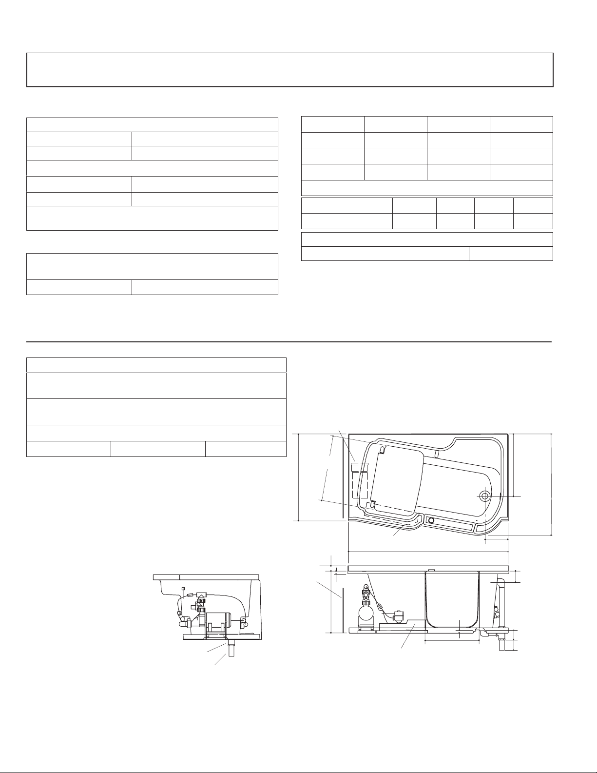
ROUGHING-IN NOTES
Fixture dimensions are nominal and conform to tolerances
in ANSI Standard Z124.1.
No change in measurements if connected with drain illustrated.
Minimum access:
Pump/control 30” W x 15” H panel required
C. PRODUCT INFORMA TION
Fixture*: basin area top area weight
Bathing well 43” x 20” 52” x 25” 188 lbs.
water depth capacity
To overflow 19-1/4” 80 gals.
* Approximate measurements for comparison only.
Pump: HP V Hz A
1-speed 2 120 60 18.5
Included Components:
Apron factory installed
D. INST ALLATION NOTES
Read the entire installation instruction before beginning the
installation.
Finished floor thickness 1/2” max. above bottom of pump
base pan. For thicker flooring, provide additional subflooring
under the bath.
PUMP
25-1/2”
23-1/8”
32”
1.25>132
114189-2-CA (9608)
2” I.P.S.
2” O.D.
AIR COMPRESSOR
1-1/2”
PUMP
ACCESS
SHOWN WITH APRON REMOVED
4
3/4”
24”
AIR COMPRESSOR
8-1/2”
60”
5/8”
20-1/2”
DOOR
OPENING
Kohler Co., Kohler WI
37-3/4”
2-1/2”
3-1/2”
3”
Page 5
2. PRODUCT NOTICES
A. INSTALLER HAZARD NOTIFICA TION
DANGER: Risk of fire, electric shock, or injury
to persons. Read important safety instructions on
inside front cover of these instructions.
WARNING: Risk of electrical shock. A licensed
electrician should make all electrical connections.
WARNING: Risk of electrical shock. Connect
only to a circuit protected by a Ground-Fault
Circuit-Interrupter (GFCI).
WARNING: Risk of electrical shock. Disconnect
power before servicing.
WARNING: Risk of injury or property damage.
Please read all instructions thoroughly before
beginning installation, including the following
Product Requirements.
NOTICE: Follow all local plumbing and electrical
codes.
3. PRODUCT REQUIREMENTS
A. SUMMAR Y OF KEY REQUIREMENTS
Install unit to a level subfloor.
Provide properly dimensioned framing.
Recess installation is recommended.
B. F ACTORY -ASSEMBLED FEATURES
K-1355-H1, K-1356-H1: Factory installed components
include pump with integral heater , control, variable flow
valve, and switch. No installation is needed.
The whirlpool pump and piping are factory-assembled.
WARNING: Unauthorized modification may
cause unsafe operation and poor performance
of the whirlpool. Do not relocate the whirlpool
pump, or make other modifications to the whirlpool
system, as this could adversely affect the
performance and safe operation of the whirlpool.
Kohler Co. shall not be liable under its warranty or
otherwise for personal injury or damage caused by
any such unauthorized modification.
B. PLUMBING SPECIFICA TIONS
Confirm adequate support for the faucet; large faucets
that may be inadvertently used as a means of support
are not appropriate or safe for this installation.
C. PRODUCT INSPECTION
Carefully uncrate and inspect your product for damage.
Do not remove the spacer bar until the unit is
secured to the stud pocket.
Return whirlpool to carton during construction to prevent
damage.
NOTICE: Make sure both union connections to the
pump are securely tightened.
E. ELECTRICAL REQUIREMENTS
The installation must have a Class A Ground-Fault
Circuit-Interrupter (GFCI). The GFCI protects against
line-to-ground shock hazard. Use a 120 V, 20 A, 60 Hz
dedicated service for the whirlpool.
D. CONNECTIONS AND SERVICE ACCESS
Before installation, ensure proper access to the final
connections.
NOTICE: Provide unrestricted service access to the
pump and controls. Removable front apron provides
access to the pump and controls.
Kohler Co., Kohler WI
5
114189-2-CA (9608)
Page 6
4. INSTALLA TION REQUIREMENTS
A. TOOLS REQUIRED
Conventional woodworking tools
Arc pliers or 14” pipe wrench
Rule
Level
Safety shoes
Safety glasses
Square
Screwdriver
Pliers
Utility knife
Tin snips
C. CLEARANCE REQUIREMENTS
Check the roughing-in and room dimensions to provide
adequate available space for the bath unit.
B. MA TERIALS REQUIRED
Plumbers putty
Wall coverings, as necessary
Silicone sealant
Construction adhesive (optional)
2x4’s
Drop cloth
Nails
D. NEW OR REPLACEMENT INSTALLA TION
REQUIREMENTS
This whirlpool can be installed in new or existing
bathrooms.
For new installations: Position the plumbing according
to the roughing-in on Page 4. Cap the supplies, and
check for leaks.
5. SITE REQUIREMENTS
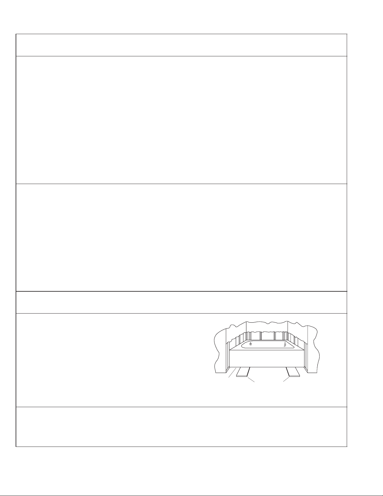
A. OLD BA TH REMOVAL
Disconnect the drain at the trap. Remove the old wall
material. Slip boards under the old bath feet to
protect the floor and slide the old bath out of the recess
as illustrated.
B. SUBFLOOR PREP ARA TION
Check the flooring under the bath, and make repairs as
needed. Make sure the subfloor is level.
For replacement installations: Remove the old bath.
Remove the old wall material, and remove any old floor
covering from the area. Remove any old plumbing that
does not conform to roughing-in requirements.
Old Bath
Floor
Protection
Boards
114189-2-CA (9608)
6
Kohler Co., Kohler WI
Page 7

C. REMOVE APRONS, AND INSPECT UNIT
Carefully uncrate and inspect the whirlpool for damage.
Do not remove spacer bar until unit is secured to
stud pocket.
Loosen and remove the screws at the base of the two
aprons. These screws secure the aprons to the pan
base. Save these screws.
Pull the bottom of the apron away from the whirlpool unit.
Then pull the top down and out from the flange in the
whirlpool rim.
Spacer
Bar
Small
Apron
Inspect the whirlpool for damage.
Reinstall the aprons if the unit is not immediately
installed.
Return the whirlpool to the carton during construction, to
prevent damage.
D. STUD POCKET PREP ARA TION
Refer to the Roughing-In section beginning on
Page 4. Measure the exact outside dimension of the
bath from the two front edges of the nailing flange. This
should be close to 60”. Size the stud pocket accordingly .
NOTE: The stud pocket must fit the width of the unit
exactly. The bath is shipped with a spacer bar to prevent
spreading or squeezing of the door opening. This would
affect the proper function of the inflatable seal and door.
Construct a recess designed for your particular
installation. Install stud pocket headers.
Construct the required access panel according to
Roughing-In section beginning on Page 4.
Design of the bath will allow for up to 1/2” of finish floor
material if the bath is installed to the subfloor. For thicker
flooring, raise bath with plywood underlayment to
compensate. This is necessary to allow clearance for
apron removal.
32” Min.
Large
Apron
Supplied Drywall Screws
Stud Pocket
Header Nailing
Flange
NOTE: Nailing
flange holes in
unit are 24-3/4”
from base of
unit
NOTE: Refer to instructions
E. PLUMBING PREPARA TION
Position the plumbing according to the roughing-in
dimensions. Cap the supplies, and check for leaks.
Kohler Co., Kohler WI
NOTE: Allow adequate clearance for plumbing.
Centerline of drain is 23-1/8” from back of unit.
7
114189-2-CA (9608)
Page 8

6. BEFORE INSTALLING UNIT
A. RECOMMENDED INST ALLA TION
Illustrated is a recommended installation.
Incorporate framing support for the vertical and
horizontal grab bars, if used. In addition, incorporate
framing support for the hand spray on vertical slide bar,
if used.
Route piping and adapt framing as necessary for the
hand spray supply elbow, pressure-balanced mixer
valve, and high-flow tub filler and valves.
Recommended
Location of Grab
Bars, if Used
B. P ARTIALL Y INSTALL BA TH DRAIN
Install the drain on the whirlpool according to the drain
manufacturer’s instructions.
C. PROTECT WHIRLPOOL UNIT
Position a drop cloth or similar material in the bottom of
the unit. Be careful not to scratch the surface of the
product.
7. INSTALL THE WHIRLPOOL
A. WHIRLPOOL SET -IN
The pump base pan is integral to the unit.
If the subfloor is level, no adjustments are required. Set
the whirlpool into place, align the drain tailpiece with the
trap, and proceed to the next section.
CAUTION: Risk of product damage. Do not use
the piping or pump for structural support or
positioning of the whirlpool.
If the subfloor is not level, some leveling of the whirlpool
area will be necessary . Do not support the weight of the
whirlpool by the flange. Do not use drywall plaster as a
means of support.
114189-2-CA (9608)
Drain Hole
Shims
8
Kohler Co., Kohler WI
Page 9

B. TO ADJUST LEVEL
Shim using minimum size 6” x 6” shims, and a maximum
spacing of 24”. Set the whirlpool into position, and align
the drain tailpiece with the trap. Make sure the whirlpool
is level.
C. CONNECT DRAIN
When the whirlpool is securely positioned, connect the
drain to the trap as shown.
D. SECURE WHIRLPOOL
Secure the nailing flange to the stud pocket header with
the screws supplied with the unit.
Drain
Plumbing
Stud
Pocket
After the unit is secured to the header to prevent
spreading or squeezing of the walls, remove the
shipping spreader bar. Test the operation of the door to
ensure there is no binding.
E. PUMP BANDING STRAP CUT
NOTICE: This step is necessary to make your
Kohler whirlpool operate more quietly.
1. Use tin snips to cut the two banding straps. These
banding straps secure the pump to the support pan
during shipping.
Pump
Suction Line
Supplied
Screws
Spacer
Bar
Banding Straps
Pump Base
Support Pan
Kohler Co., Kohler WI
Subfloor
9
114189-2-CA (9608)
Page 10

8. COMPONENT LOCATION
Familiarize yourself with the location of all major
components before proceeding to the wiring (as
required), trim kit installation, testing, and
troubleshooting.
This unit uses a compressor assembly to inflate a seal
in the door. The door has a backup gasket on the outside
for added safety.
A bolt-type latch secures the door. It is released by the
button on top of the door. After the button is depressed,
slight pressure inward should open the door.
This unit is different from many other Kohler whirlpools
in that the power for the whirlpool pump and controls is
supplied through the compressor assembly control box.
9. ELECTRICAL CONNECTIONS
A. IDENTIFY ELECTRICAL REQUIREMENTS
The model number is printed on a label at the pump end
of the whirlpool.
The label identifies electrical rating.
Control
Switch
Seat
Pump
Jet
Suction
Button
Inflatable
Seal
Door
Backup
Gasket
Hose
Air Compressor
B. FIELD WIRING COMP ARTMENT – 120 V, 60
HZ, -H1 (UL LISTED) MODELS
WARNING: Risk of electrical shock. Make sure
the power has been disconnected before
performing the following procedures. Refer to
Important Safety Instructions located on Page 2.
CAUTION: Risk of electrical shock. All services
must have a Class A Ground-Fault
Circuit-Interrupter (GFCI) which will provide
additional protection against line-to-ground shock
hazard. A dedicated service is required for the
whirlpool.
The whirlpool controls and system have been prewired
at the factory. A licensed electrician should make a
routine service connection to the compressor box
accessible through the apron.
* For bonding in accordance with national and local
codes.
Pump
Switch
Bonding
(Earthing) Lugs*
Compressor Box
Pump
Control Box
114189-2-CA (9608)
10
Kohler Co., Kohler WI
Page 11

C. CONNECT COMPRESSOR BOX, -H1 (UL
LISTED) MODELS
Connect service to the field wiring compartment of the
compressor box. The compressor control contains black
and white wires and a ground lug. The compressor
control is prewired to the whirlpool pump.
Black
Wire
(Line)
Wire
Nut
White Wires
(Neutral)
Water-Level
Sensor
A 120 V, 20 A dedicated circuit is required. Provide a
Class A Ground-Fault Circuit-Interrupter (GFCI).
Provide a separate equipment grounding conductor for
the inside grounding lug. Ground must not be
connected to any current-carrying conductor.
10. INSTALL WHIRLPOOL TRIM KIT
Refer to the installation instructions packed with the trim
kit when installing the jet or suction trim.
Bonding
Lug
Green
Wire
(Ground)
Ground
Lug
To Pump
Kohler Co., Kohler WI
11
114189-2-CA (9608)
Page 12

1 1. TEST DOOR SYSTEM
A. OPERA TING SEQUENCE
Tightly close the door. When swinging the door shut, a
clicking sound assures the door is closed and secure.
Check that the door latch engages the latch receptor.
Close the drain, and begin filling the bath.
The door seal will inflate automatically after the two
water-level sensors (inside the bath, and near the
bottom of the door) are covered with water.
Latch Button
Water
Line
Monitor the outside of the door for any signs of leakage,
and continue to fill the bath to a level at least 2” above
the top of the highest jet.
Open the drain, and allow the bath to empty.
The door seal will automatically deflate when the water
level reaches below the water-level sensors.
Press in the button on the top of the door, and open the
door inward.
Suction
2” Min.
Whirlpool
Jet
B. TROUBLESHOOT DOOR SYSTEM
This troubleshooting guide is for general aid only. A Kohler Authorized Service Representative or a qualified electrician
should correct all electrical problems. For warranty service, contact your dealer or wholesale distributor.
SYMPTOMS PROBABLE CAUSES RECOMMENDED ACTION
1. Door won’t close. A. Seal is out of track. A. Re-insert seal.
B. Seal remains inflated. B. Contact dealer/installer.
C. Improper installation. C. Contact dealer/installer.
2. Door won’t open. A. Bath is not empty. A. Wait for bath to empty.
B. No power to unit. B. Reset breaker.
C. Compressor controller. C. Contact dealer/installer.
3. Door leaks water. A. No power to unit. A. Reset breaker.
B. Incorrect field wiring. B. Contact dealer/installer.
C. Seal is leaking. C. Contact dealer/installer.
D. Compressor controller. D. Contact dealer/installer.
4. Compressor runs
periodically.
114189-2-CA (9608)
A. Seal is leaking air. A. Contact dealer/installer.
B. Faulty pressure switch. B. Contact dealer/installer.
12
Kohler Co., Kohler WI
Page 13

12. WATER TEST WHIRLPOOL AND ELECTRONICS
Check all electrical connections.
Make sure all pipe connections to the pump are securely
tightened.
Fill the whirlpool to a level at least 2” above the top of the
highest jet.
Operate the whirlpool for 5 minutes, and check all
whirlpool harness (piping) connections for leaks.
For additional information on whirlpool operation, see
Start-Up Whirlpool instructions on Page 15.
13. INSTALL APRONS
Locate the screws removed during the whirlpool
inspection.
This apron system is designed so the finish wall
materials go over the apron columns. It is also designed
so the finished floor materials butt up against the pan
base.
Slip the top of an apron up into the channel groove. Tilt
the apron inward. Align the bottom of the apron with the
pan base. The apron should align with both the bath rim
and the edges of the apron columns, and with the
pre-drilled holes in the pan base.
Secure the apron to the pan base with screws.
Repeat for the other apron.
Large Apron
Supplied Drywall Screw
Small
Apron
Supplied Drywall
Screws
Kohler Co., Kohler WI
13
114189-2-CA (9608)
Page 14

14. INSTALL FINISH W ALL
NOTICE: Before covering the framing, perform the
following procedure: Open the hot and cold water
valves, and check all supply connections for leaks. Fill
the whirlpool to the overflow, and check the overflow and
drain connections for leaks. Operate the whirlpool for 5
minutes, and again check all connections for leakage.
Protect the whirlpool surface. Cover the framing and
walls with water-resistant wall material. Tape and mud
the wall material. Seal the wall material and joints under
the whirlpool rim. Install the finish wall material to the
subwall. Use silicone sealant to seal the joints between
the whirlpool rim and the finish wall.
15. INSTALL KICK STRIP
NOTE: Install kick strip after the finished flooring is
installed.
With the paper backing still attached, position the kick
strip along the outline of the whirlpool base.
Stud
Water-Resistant Wall
Material
Finish Wall
Covering
Silicone
Sealant
Whirlpool
Begin at one end, and peel back a few inches of the
paper backing from the kick strip.
Align the end of the kick strip to the finish wall and the
bottom of the whirlpool base. Lightly press the kick strip
to the whirlpool base.
Peeling back a few inches of paper backing at a time,
continue aligning and pressing the kick strip to the
whirlpool base.
After the kick strip is completely applied, go over the
entire length with firm pressure to secure the kick strip
to whirlpool base.
Kick strip
114189-2-CA (9608)
14
Kohler Co., Kohler WI
Page 15

16. CLEAN-UP AFTER INST ALLATION
When cleaning up after installation, do not use
abrasive cleansers as they may scratch and dull the
bath surface. Use warm water and a liquid detergent to
clean the surface.
Stubborn stains, paint, or tar can be removed with
turpentine or paint thinner. Do not allow cleaners
containing petroleum distillates to remain in
contact with whirlpool surfaces for long periods of
time. Plaster can be removed by scraping with a wood
edge. Do not use metal scrapers, wire brushes, or other
metal tools. A powder-type detergent may be used on a
damp cloth to provide mild abrasive action to the residual
plaster.
17. CONFIRM PROPER OPERATION
A. ST ART-UP WHIRLPOOL
Refer to Important Safety Instructions on Page 2.
Please perform the following so the owner can safely
receive the benefits of whirlpool bathing.
1. Rotate the jets so they are facing down toward the
basin.
Polystyrene
Bath
Wall
FRP
Polystyrene
Water Line
2” Minimum
2. Fill the whirlpool to a water level at least 2” above
the top of the highest jet.
Water temperature in the bath should not exceed
104F (40C).
Jet Trim
Kohler Co., Kohler WI
15
114189-2-CA (9608)
Page 16

B. OPERA TING SEQUENCE
Refer to the chart at right for the proper operating
sequence.
1. Turn on the whirlpool jets. Adjust each jet for
optimum air/water mixture.
2. A built-in timer automatically stops the motor after
20 minutes of operation.
3. A built-in heater automatically maintains the water
temperature while whirlpool bathing.
ALL 2-HP, VARIABLE FLOW MODELS:
TO METHOD OBSERVE
Turn on
whirlpool
massage and
the heater.
Decrease flow by
pressing ↓ key;
increase flow by
pressing ↑ key.
Up/
More
Down/
Less
To add air and
water to whirlpool
action, rotate
the flange
counterclockwise.
To reduce air and
water, rotate it
clockwise.
Shut off whirlpool.
Restart whirlpool
after 20 minute
cycle is
complete.
Reduce
Air and
Water
Add Air
and
Water
114189-2-CA (9608)
16
Kohler Co., Kohler WI
Page 17

18. TROUBLESHOOTING PROCEDURES
A. FLEXJET INST ALLA TION
NOTE: The Flexjet O-ring must be correctly positioned,
must be lubricated, and must be in good condition to
permit easy rotation and proper operation.
Flexjet Housing
1. Install the O-ring onto the first shoulder of the
Flexjet. Lubricate the O-ring with silicone lubricant
to prevent noisy operation of the Flexjet.
2. Insert the Flexjet into the housing, and lightly push
and rotate the Flexjet until it snaps into position. Do
not force the Flexjet.
NOTE: When installed correctly , the Flexjet should turn
smoothly both clockwise and counterclockwise.
Slide O-Ring
Flexjet
O-Ring (Must
Be Lubricated)
Kohler Co., Kohler WI
17
114189-2-CA (9608)
Page 18

B. TROUBLESHOOT WHIRLPOOL SYSTEM
before 18 minutes
This troubleshooting guide is for general aid only. A Kohler Authorized Service Representative or a qualified electrician
should correct all electrical problems. For warranty service, contact your dealer or wholesale distributor.
SYMPTOMS PROBABLE CAUSES RECOMMENDED ACTION
1. Whirlpool does not
start/stop.
2. Motor starts, all jets
are not functioning.
3. Whirlpool stops
automatically
before 18 minutes.
A. No power to pump motor. A. Set/Reset GFCI breaker; check
wiring.
B. Faulty switch. B. Replace switch.
C. Jets are blocked. C. Remove blockage.
D. Faulty pump circuit board. D. Replace pump circuit board.
E. Switch disconnected from panel. E. Reconnect wire at switch or at pump.
F. Faulty motor/pump assembly. F. Replace motor and pump.
A. Jet is closed. A. Rotate jets counterclockwise to open.
B. Trim kit installed incorrectly. B. Reinstall trim kit, checking for damage
to O-ring.
C. Jets are blocked. C. Remove blockage.
A. GFCI trips. A. Identify source of fault and correct.
B. Suction blocked. B. Remove obstruction.
.
C. Jets are blocked. C. Remove blockage.
D. Motor overheated and protection
device activated.
D. Check for blockage at motor vents.
Remove blockage and allow motor to
cool.
Check for suction blockage. Remove
blockage and allow motor to cool.
Check for jet blockage. Remove
blockage and allow motor to cool.
E. Faulty pump circuit board. E. Replace pump circuit board.
4. Whirlpool does not
automatically stop
after 22 minutes.
5. Jet squeals/is noisy. A. O-ring unseated. A. Remove jet. Replace and lubricate
6. Whirlpool is noisy. A. Shipping straps holding pump to bath
7. Water flow cannot
be regulated.
A. Faulty pump circuit board. A. Replace pump circuit board.
O-ring onto jet valve body; reinstall
jet.
A. Cut straps so pump sits on subfloor.
have not been cut.
A. Faulty flow valve. A. Check for loose connections or
wire(s) leading to pump. Replace flow
valve or pump circuit board as
necessary.
114189-2-CA (9608)
18
Kohler Co., Kohler WI
Page 19

Kohler Co., Kohler WI
19
114189-2-CA (9608)
Page 20

114189-2-CA (9608)
Kohler Co., Kohler WI
 Loading...