

Page 1
Installation and Care Guide
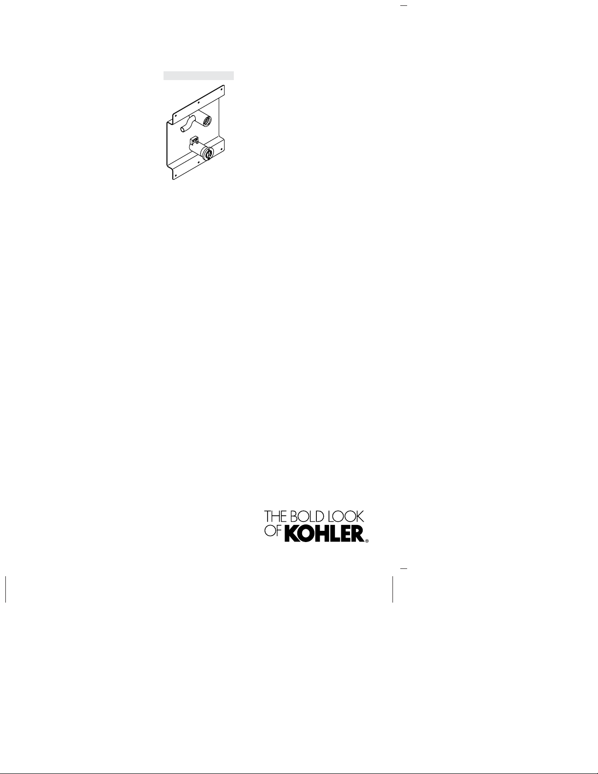
Wall-Mount Valve
K-11842, K-11843
M product numbers are for Mexico (i.e. K-12345M)
Los números de productos seguidos de
M corresponden a México (Ej.
K-12345M)
Français, page “Français-1”
Español, página “Español-1”
1207552-2-B
Page 2
September 22, 2009
08
EC DECLARATION OF CONFORMITY
Kohler Company
444 Highland Drive, Kohler, WI 53044
Phone 920-457-4441
We declare under our sole responsibility that the product AC models:
Electronic Wall-Mount Lavatory
Faucet (Tap) – AC Power
K-11842
K-11842W
K-11842IN
K-11842M
K-11842D
K-11842T
K-E 11842
AC Power Supply
K-13480
to which this declaration relates, are in conformity with the relevant European Community
Directive(s):
Electromagnetic Compatibility (EMC) Directive 2004/108/EC
Conformity to this directive is based on compliance with the following harmonized standards:
• EN 61000-6-2: 2005
Electromagnetic Compatibility (EMC) – Radiated Immunity, 80MHz to 1GHz
(Test method: IEC 61000-4-3: 2008)
• EN 61000-6-3: 2007
Radiated Emission(Test Method: CISPR 16-2-3): CLASS B
On behalf of Kohler Co.,
K-11843
K-11843W
K-11843IN
K-11843M
K-11843D
K-11843T
K-E 11843
K-13481
Timothy J. Stessman
Codes & Standards Dept.
Kohler Company
Signature
September 22, 2009
Date
Declaration of Conformity
1207552-2-B 2 Kohler Co.
Page 3
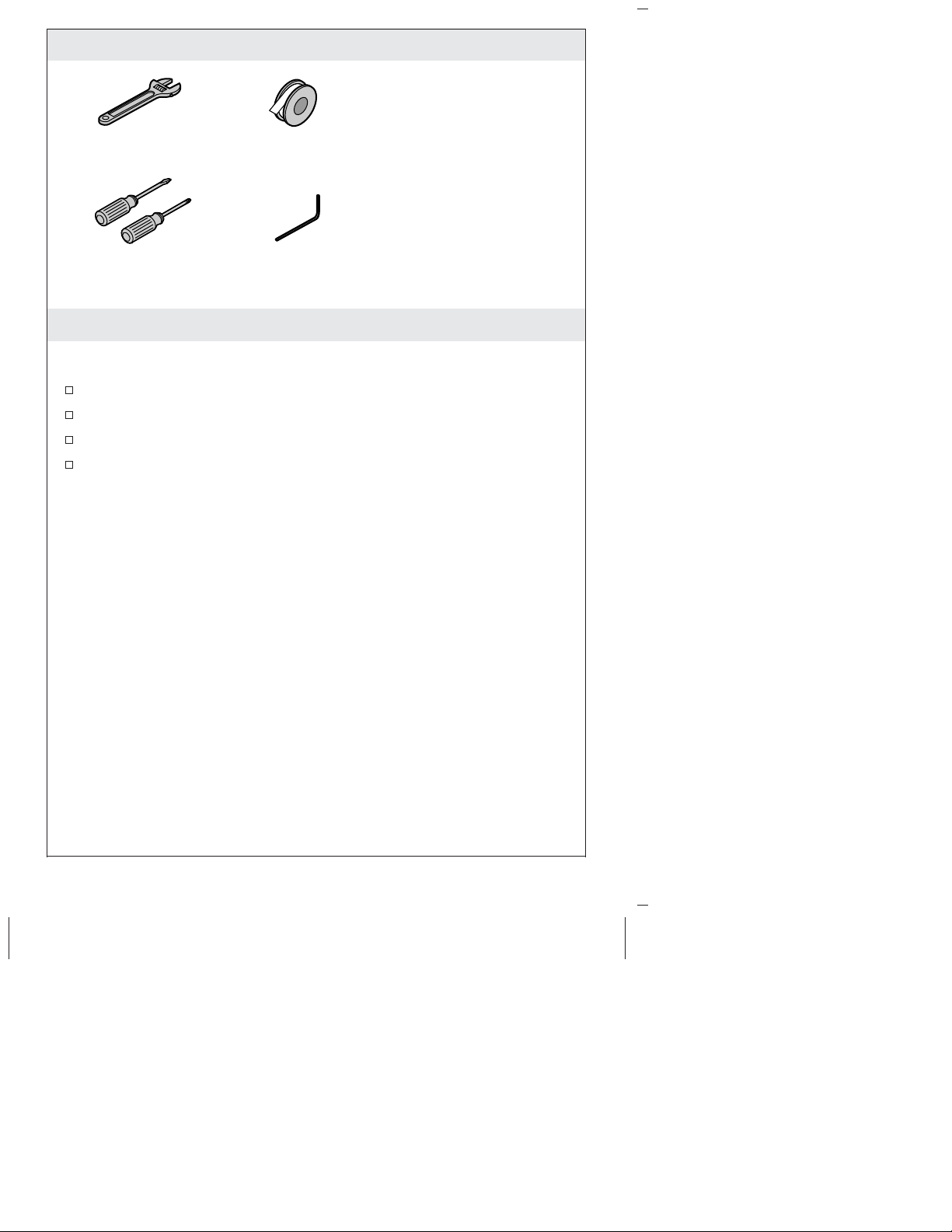
Tools
Plus:
• Wire Fasteners
Adjustable
Wrench
Screwdrivers
Sealant Tape
Hex WrenchAssorted
• Woodworking Tools
• Pipe Fitting Tools
• Wood Screws
• 2x4s
Important Information
NOTE: Follow the installation dimensions precisely as there is no
deep rough-in kit available for this product.
Observe all local plumbing and building codes.
Shut off the main water supply.
Inspect the supply tubing for damage. Replace as necessary.
Site preparation and wall finishing may require additional tools
and materials.
Kohler Co. 3 1207552-2-B
Page 4
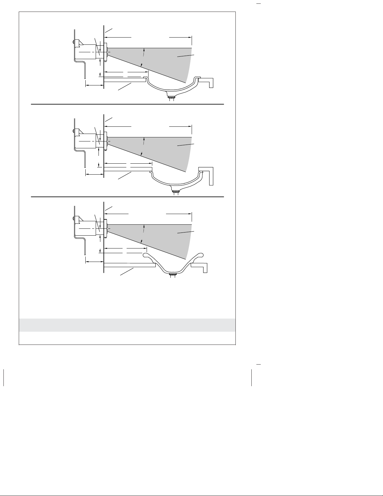
Drop-In
Sinks
1/2"
(13 mm)
*
Countertop
Finished Wall
Y
11" (279 mm)
Motion
Zone
20˚
X
Under-Mount
Sinks
Above-Counter
Sinks
Important:
Measure "Y"
from the sink rim,
not the countertop.
1/2"
(13 mm)
*
Countertop
1/2"
(13 mm)
*
Countertop
Y
Y
Finished Wall
11" (279 mm)
20˚
X
Finished Wall
11" (279 mm)
20˚
X
Motion
Zone
Motion
Zone
* Consult the specification sheet for the spout that will be paired with
this valve for specific installation dimensions.
1. Determine the Sensor Location
1207552-2-B 4 Kohler Co.
Page 5
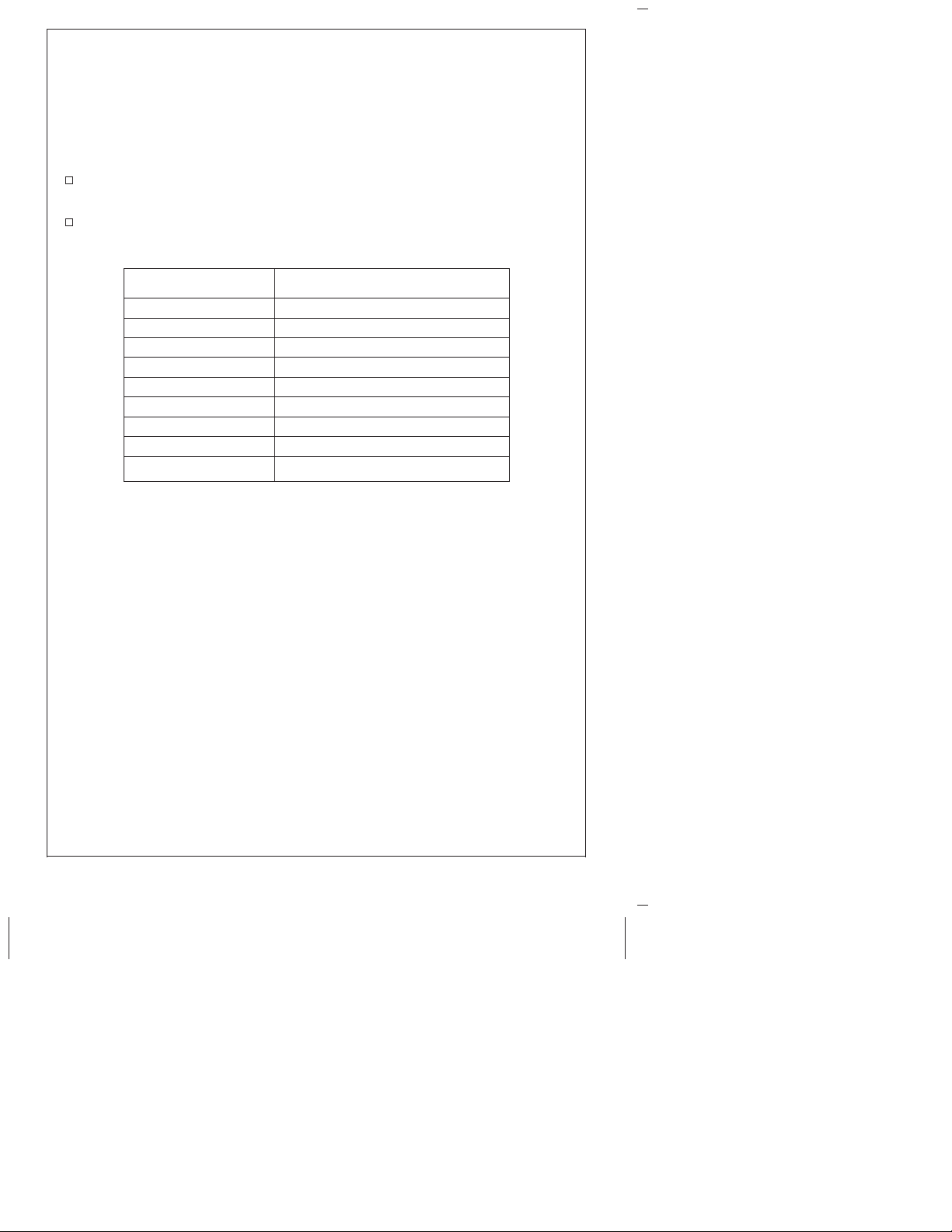
Determine the Sensor Location (cont.)
IMPORTANT! It is critical for proper operation that the sensor be
installed with the motion zone clear of any obstructions, including
the edge of the countertop or the bathroom sink.
NOTE: Before installation, consult the specification sheet for the
spout to determine the correct wall rough-in for your installation.
Measure the distance (X) from the finished wall to the inside edge
of the countertop or bathroom sink.
Determine the sensor height (Y) using the chart below. If you
cannot determine Y from the chart, use the formula .5″ + X(0.364)
to determine (Y).
If dimension X is: Then the sensor height (Y) is:
1″ (25 mm) 7/8″ (48 mm)
2″ (51 mm) 1-1/4″ (32 mm)
3″ (76 mm) 1-9/16″ (40 mm)
4″ (102 mm) 2″ (51 mm)
5″ (127 mm) 2-3/8″ (60 mm)
6″ (151 mm) 2-9/16″ (65 mm)
7″ (179 mm) 3″ (76 mm)
8″ (203 mm) 3-7/16″ (87 mm)
9″ (229 mm) 3-3/4″ (95 mm)
Kohler Co. 5 1207552-2-B
Page 6
Six Round Holes (Typical)
Wall Plate
Screws
Finished
Wall
*
*Consult the spout
specification sheet
for specific installation
dimentions.
16"
(406 mm)
7" (178 mm)
*
2x4 Stud Framing
Sink Height
2. Prepare the Site
IMPORTANT! The valve requires special framing and support
considerations. Consult the specification sheet for the spout that will
be installed with your valve at www.kohler.com for specific
dimensions.
NOTE: Mount the valve with the sensor at the height determined in
the previous step.
NOTE: A suggested framing example is shown. Each installation
may have different framing requirements than those shown.
Construct the framing for your installation.
If a thermostatic mixing valve will be included with your
installation, install the valve now following the directions
provided with the valve.
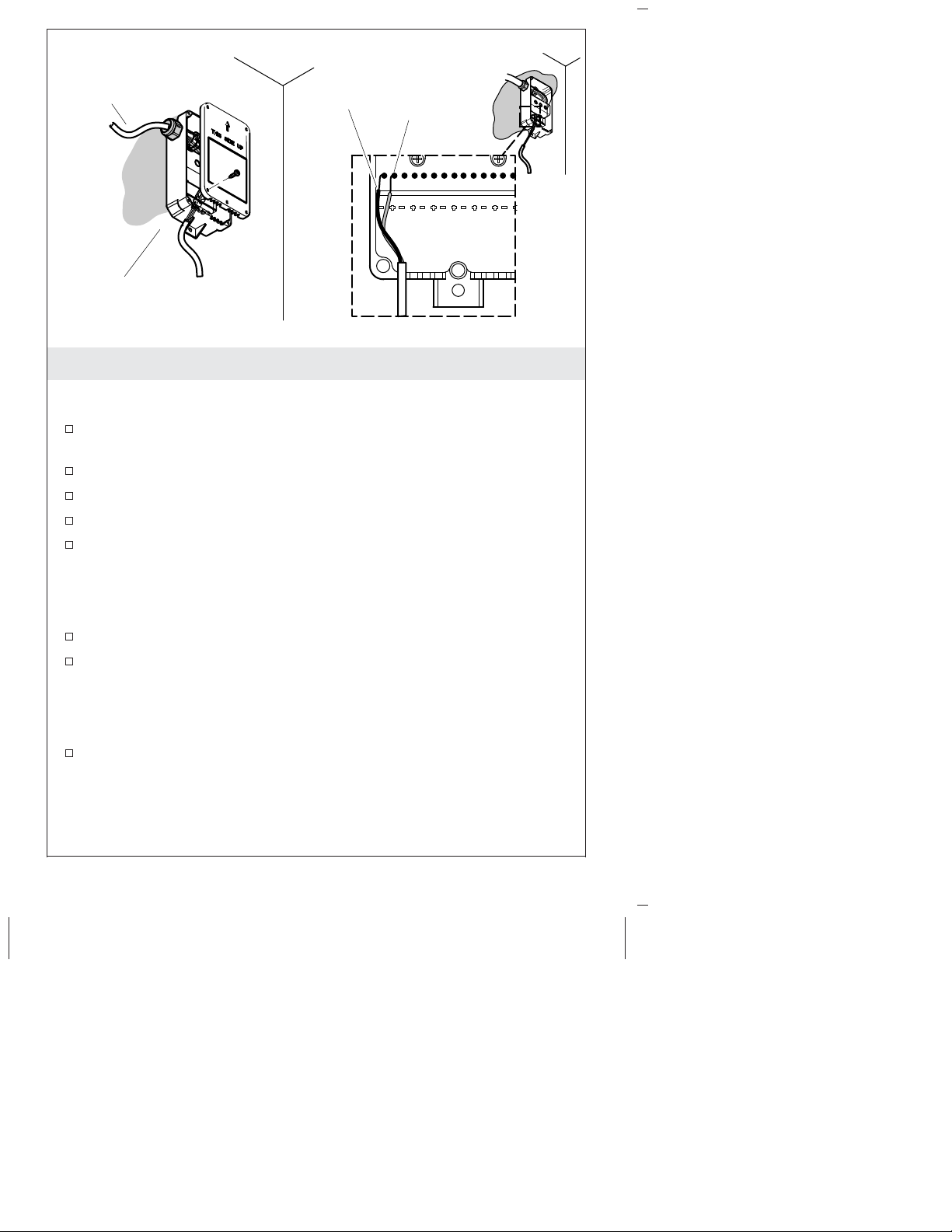
3. Secure the Valve
IMPORTANT! Make sure the location of the valve is correct before
securing it in place. The centerline of the drain and faucet should be
in line with each other.
1207552-2-B 6 Kohler Co.
Page 7
Secure the Valve (cont.)
Secure the wall plate to the studs using six wood screws (not
provided).
Kohler Co. 7 1207552-2-B
Page 8
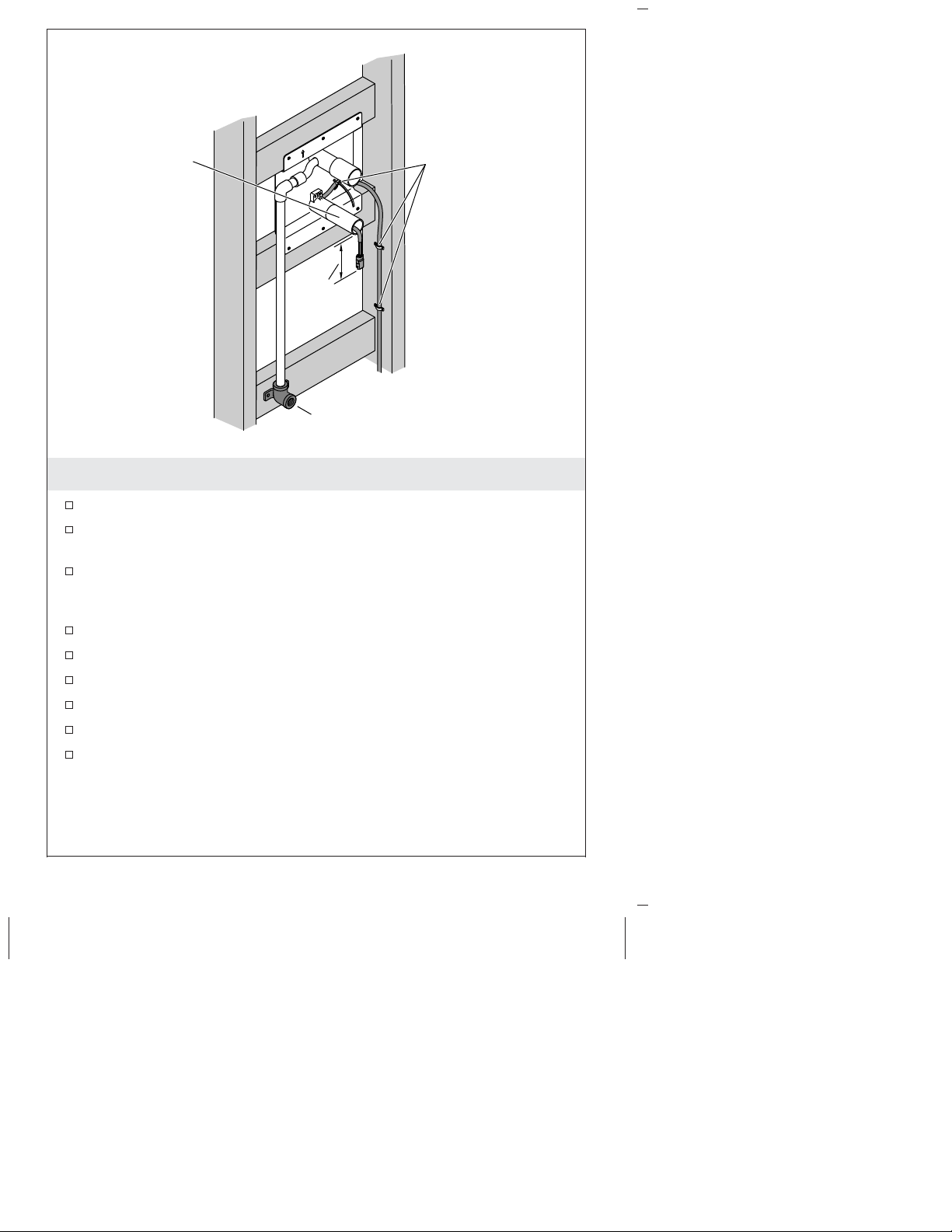
Plaster Guard
1-1/2"
(38 mm)
Ell
harness to the wall.
4. Install the Pipe and Finished Wall
Install 1/2″ supply pipe to the valve assembly.
At the point where the supply will exit the wall, install a drop ear
ell flush or slightly behind the finished wall.
Feed the sensor wire through the sensor mount and plaster
guard, leaving 1-1/2″ (38 mm) minimum of exposed wire
protruding.
Connect the sensor wire harness to the wall.
Temporarily connect the water supply to the supply ell.
Turn on the water.
Check the system for leaks.
Turn off the water.
Install the finished wall.
Secure wire
NOTE: The diameter of the faucet hole cutout is 1-3/4″ (44 mm).
The diameter of the sensor hole cutout is 1-3/8″ (35 mm).
1207552-2-B 8 Kohler Co.
Page 9

Install the Pipe and Finished Wall (cont.)
NOTE: The diameter of the supply inlet opening is determined by
the ell diameter.
Kohler Co. 9 1207552-2-B
Page 10
Sensor Wire
Bezel
Discard the
plaster guard.
Sensor
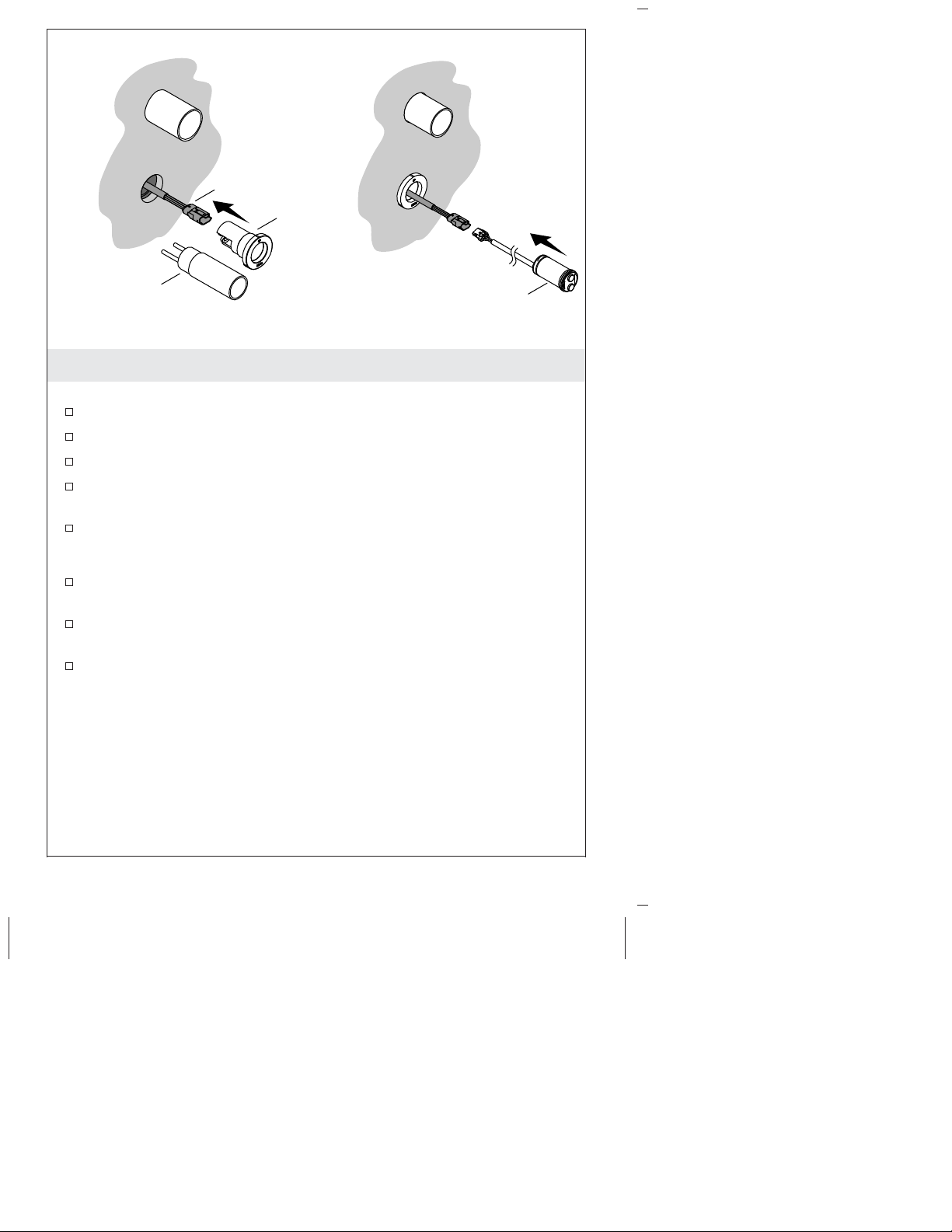
5. Install the Sensor
Install the Bezel
Loosen the screws in the plaster guard.
Remove the plaster guard and discard.
Feed the sensor wire through the back of the bezel.
Position the bezel over the screw heads and turn 1/8 turn
counterclockwise.
Tighten the screws.
Connect the Sensor
Connect the sensor to the wire harness and feed the wire into the
wall.
Position the sensor in front of the bezel with the wire on the back
of the sensor to the right.
Push the sensor into place.
1207552-2-B 10 Kohler Co.
Page 11
Control Box
Screws
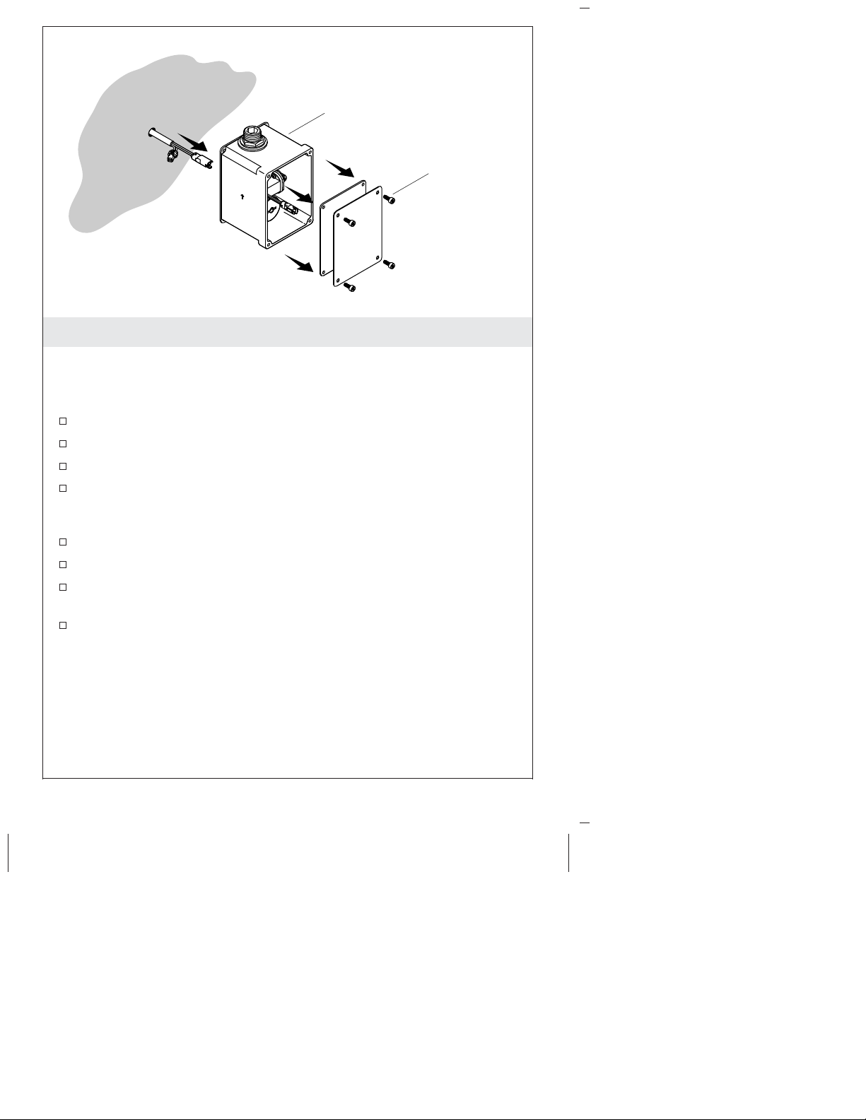
6. Install the Control Box
NOTE: Locate the sensor box underneath the countertop, between
the ell and the water supply stop.
NOTE: Do not connect the control box wiring in this step.
Drill a 1/2″ (13 mm) hole at the control box location.
Route the sensor wire through the hole.
Remove the control box cover. Keep the screws and cover.
Mark the screw hole locations using the control box as a template.
Make sure the wire harness hole in the wall is covered by the
box.
Install appropriate wall anchors (not provided) at the marks.
Feed the wires through the back of the valve and control box.
Attach the control box to the wall with two screws (not
provided).
Connect the solenoid wires (red and green).
Kohler Co. 11 1207552-2-B
Page 12
Hex Hole
Ell
Outlet
Inlet
Round Hole
Outlet
Inlet
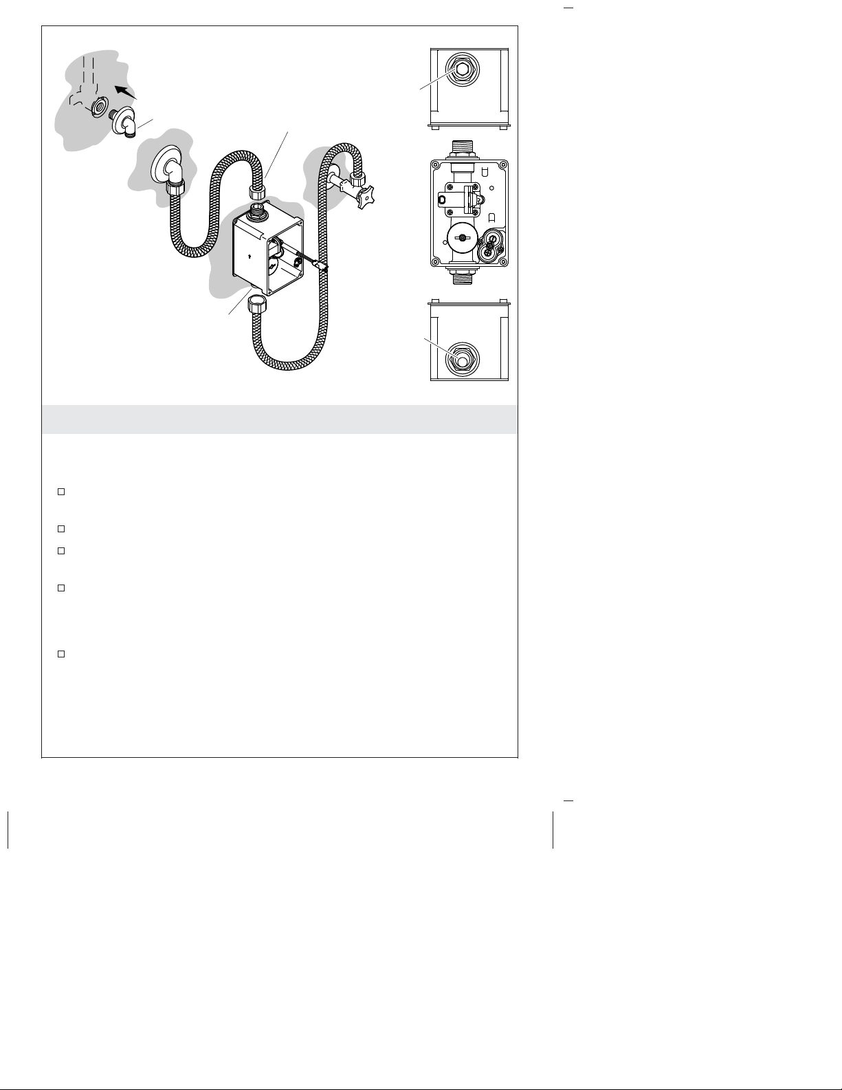
7. Install the Supplies
IMPORTANT! It is critical that the inlet and outlet holes be aligned
correctly. The inlet hole is round, the outlet hole is hex shaped.
There is a label on the outlet side identifying it.
Slide the escutcheon over the elbow and attach the elbow to the
ell.
Slide the escutcheon tight against the wall.
Attach one end of the hose to the elbow and attach the other end
of the hose to the control box outlet.
Attach the supply hose to the control box inlet.
NOTE: If the water supply does not route through a mixing valve,
the water from the faucet will be cold.
Attach the other end of the line to a thermostatic mixing valve
(recommended), mixing valve, or supply stop.
1207552-2-B 12 Kohler Co.
Page 13
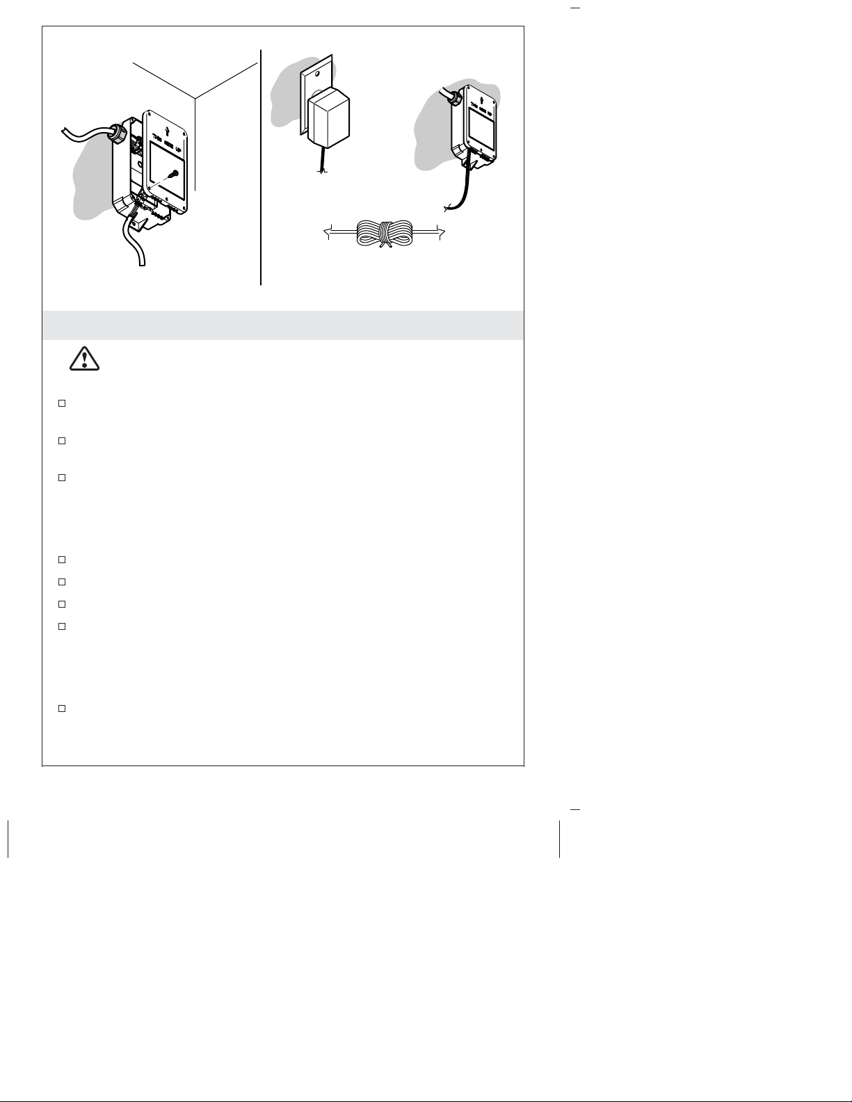
AC Supply
Faucet
Wire
Plug the AC supply
into the wall outlet.
Secure any excess
wire under the counter.
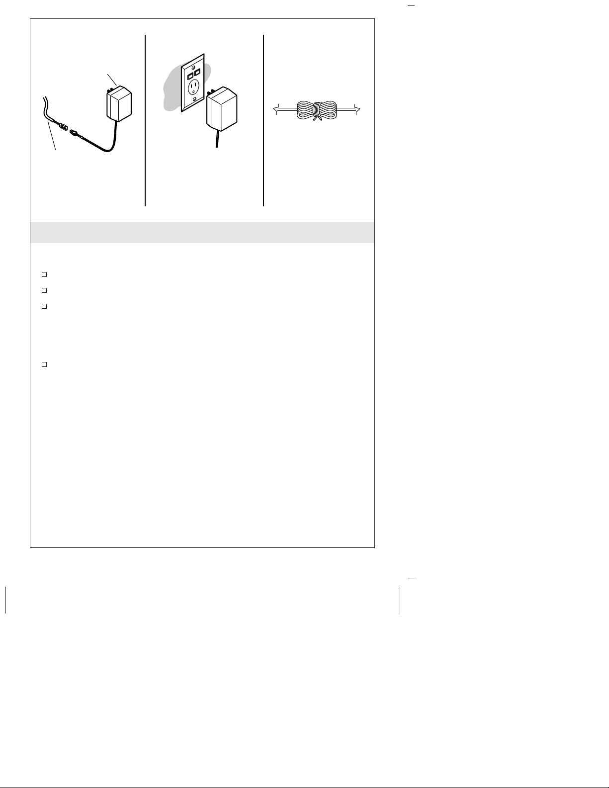
8. Install AC Single Supply
Single Faucet Installations
Connect the faucet wire to the AC supply.
Plug the AC supply into the wall outlet.
Secure the excess wire under the counter.
IMPORTANT! The area in front of the sensor must be free of
objects during the 2 minute learning cycle or faucet may not
function properly.
Allow 2 minutes for the sensor to cycle through the automatic
sensing distance.
Kohler Co. 13 1207552-2-B
Page 14
AC Supply
AC Gang
Supply
Black
Red
9. Install AC Multi-Outlet Supply
Multiple Faucet Installations - AC Only
Mount the AC supply under the counter using two screws (not
supplied). Orient as shown.
Remove the cover.
Connect the faucet wire to the faucets.
If needed, cut and strip the AC supply wires to length.
Connect the stripped ends to the bottom terminal block (TB2) in
the supply box.
NOTE: If a hard wired installation is required go to the next
installation section.
Plug the AC supply into the wall outlet.
Secure any excess wire under the counter.
IMPORTANT! The area in front of the sensor must be free of
objects during the 2 minute learning cycle or the faucet may not
function properly.
Allow 2 minutes for the sensor to cycle through the automatic
sensing distance.
1207552-2-B 14 Kohler Co.
Page 15
Secure any excess
wire under counter.
10. Hard Wire Installation
CAUTION: Risk of electric shock. Make sure the power has
been disconnected before performing the following
procedures.
Loosen the terminal block screws and remove the wires from the
top terminal block.
Loosen the outside nut of the strain relief and remove the power
cord.
Put the supply wires through the strain relief and connect them
to the top terminal block.
NOTE: If a hard wired installation is required the strain relief may
need to be replaced depending on the wire used.
Tighten the nut on the strain relief.
Replace the cover, and install and tighten the four screws.
Turn on the AC supply power.
Secure any excess wire under the counter.
IMPORTANT! The area in front of the sensor must be free of
objects during the 2 minute learning cycle or the faucet may not
function properly.
Allow 2 minutes for the sensor to cycle through the automatic
sensing distance.
Kohler Co. 15 1207552-2-B
Page 16
11. Complete the Installation
NOTE: Avoid the area in front of the sensor for 2 minutes after
connections are complete. The sensor will not function correctly if it
is triggered in the first 2 minutes. Disconnect and reconnect the
power to reset the sensor.
Avoid the area in front of the sensor for 2 minutes.
Install the faucet trim following the directions provided.
Turn the water on.
Test the faucet.
Check for leaks.
Warranty
KOHLER®Electronic Faucets, Valves and Controls
FIVE-YEAR LIMITED WARRANTY
Kohler Co. warrants that its electronic faucets, valves and controls will
be free of defects in material and workmanship during normal
residential use for five years from the date the product is installed.
This warranty applies only to electronic faucets, valves and controls
installed in the United States of America, Canada and Mexico (″North
America″).
If a defect is found in normal residential use, Kohler Co. will, at its
election, repair, provide a replacement part or product, or make
appropriate adjustment where Kohler Co.’s inspection discloses any
such defect. Damage caused by accident, misuse, or abuse is not
covered by this warranty. Improper care and cleaning will void the
warranty*. Proof of purchase (original sales receipt) must be provided
to Kohler Co. with all warranty claims. Kohler Co. is not responsible
for labor charges, installation, or other incidental or consequential costs
other than those noted above. In no event shall the liability of Kohler
Co. exceed the purchase price of the faucet, valve or control.
If the electronic faucets, valves or controls are used commercially or are
installed outside of North America, Kohler Co. warrants that the
faucet, valve or control will be free from defects in material and
workmanship for one (1) year from the date the product is installed,
with all other terms of this warranty applying except duration.
If you believe that you have a warranty claim, contact your Home
Center, Dealer, Plumbing Contractor or E-tailer. Please be sure to
provide all pertinent information regarding your claim, including a
complete description of the problem, the product, model number, the
date the product was purchased, from whom the product was
purchased and the installation date. Also include your original invoice.
For other information, or to obtain the name and address of the service
1207552-2-B 16 Kohler Co.
Page 17
Warranty (cont.)
and repair facility nearest you, write Kohler Co., Attn: Customer Care
Center, Kohler, Wisconsin 53044 USA, or by calling 1-800-4-KOHLER
(1-800-456-4537) from within the USA and Canada, and
001-800-456-4537 from within Mexico, or visit www.kohler.com within
the USA, www.ca.kohler.com from within Canada, or
www.mx.kohler.com in Mexico.
THE FOREGOING WARRANTIES ARE IN LIEU OF ALL OTHER
WARRANTIES, EXPRESS OR IMPLIED, INCLUDING BUT NOT
LIMITED TO THE IMPLIED WARRANTIES OF
MERCHANTABILITY AND FITNESS FOR A PARTICULAR
PURPOSE.
KOHLER CO. AND/OR SELLER DISCLAIM ANY LIABILITY FOR
SPECIAL, INCIDENTAL OR CONSEQUENTIAL DAMAGES. Some
states/provinces do not allow limitations on how long an implied
warranty lasts or the exclusion or limitation of such damages, so
these limitations and exclusions may not apply to you. This warranty
gives the consumer specific legal rights. You may also have other
rights that vary from state/province to state/province. This warranty
is to the original consumer purchaser only, and excludes product
damage due to installation error, product abuse, or product misuse,
whether performed by a contractor, service company, or the
consumer.
This is Kohler Co.’s exclusive written warranty.
*Never use cleaners containing abrasive cleansers, ammonia, bleach,
acids, waxes, alcohol, solvents or other products not recommended
for chrome. This will void the warranty.
Troubleshooting
NOTE: For service parts information, visit your product page at
www.kohler.com/serviceparts.
This troubleshooting guide is for general aid only. For service and
installation issues or concerns, call 1-800-4KOHLER.
Symptoms Probable
1. No water
flow.
Kohler Co. 17 1207552-2-B
Causes
A. Filter is
plugged.
B. Sensor eyes
are dirty.
Recommended Action
A. Clean or replace the filter.
B. Wipe the sensor eyes with a
damp soft cloth. Wipe dry with a
dry soft cloth.
Page 18

Troubleshooting (cont.)
Symptoms Probable
Causes
C. Water not
turned on.
D. Incorrect
installation.
E. The aerator
is plugged.
F. Sensor eyes
are scratched.
G. A flex hose
is kinked.
H. Power
supply is
interrupted.
I. No power. I. Replace the power supply.
J. Bleed hole
in diaphragm
is plugged or
debris exists
on the seal.
K. Solenoid
does not work.
2. Low flow. A. Filter is
plugged.
B. Supply
pressure is
low.
C. Aerator is
plugged.
Recommended Action
C. Verify that the water supply is
turned on and that pressure is at
least 20 psi (137 kPa).
D. Verify that the faucet is mounted
as instructed in the installation
instructions. Ensure that the sensor
eyes are above the rim of the sink.
Refer to the installation
instructions.
E. Remove and clean the aerator.
For calcium/mineral deposits, soak
the plastic insert in a 50:50 mix of
water and vinegar. Soak only the
plastic insert.
F. Replace the sensor assembly.
G. Check the flex hoses to make
certain they are not kinked. If a
flex hose is kinked, disconnect it,
straighten, and reconnect.
H. Wait 2 minutes after power is
restored, as the sensor cycles
through the learning cycle.
J. Clean or replace the diaphragm.
K. Install a new solenoid assembly.
A. Clean or replace the filter.
B. Check incoming water pressure.
Pressure should be at least 20 psi
(137 kPa).
C. Remove the aerator and clean it.
For calcium/mineral deposits, soak
the aerator plastic insert in a 50:50
mixture of vinegar and water. Soak
only the insert and no other
components.
1207552-2-B 18 Kohler Co.
Page 19

Troubleshooting (cont.)
Symptoms Probable
Causes
3. Constant
water flow.
A. Filter is
plugged.
B. Diaphragm
seal is
damaged or
dirty.
C. Solenoid
does not work.
4. Sporadic
water flow.
A. The faucet
is angled
incorrectly to
deck or
misaligned
with user area.
B. The wires
are pinched or
damaged.
5. Sensor
flashes once
A. Low
voltage.
approximately
every 2
seconds. The
product
continues to
operate.
6. Sensor
flashes once
A. Low
voltage.
approximately
every 2
seconds. The
product does
not operate.
Recommended Action
A. Clean or replace the filter.
B. If the diaphragm is cut or torn,
order a new diaphragm assembly.
Clean or replace the diaphragm.
C. Install a new solenoid assembly.
A. Verify that the faucet is mounted
according to the installation
instructions. Ensure that the faucet
is installed in a position that is
above the rim of the sink.
B. Remove the spout and verify
that the wires are tucked inside the
spout before reassembling.
A. Replace the power supply.
A. Replace the power supply.
Kohler Co. 19 1207552-2-B
Page 20

Guide d’installation et d’entretien
Vanne à montage mural
Outils
Plus:
• Fixations câble
Clé à molette Ruban
d'étanchéité
Clés hexagonaleTournevis assortis
Informations importantes
NOTA: Suivre les dimensions d’installation de manière précise,
étant donné qu’aucun kit de raccordement profond n’est disponible
pour ce produit.
Respecter tous les codes de plomberie et de bâtiment locaux.
Couper l’arrivée d’eau principale.
Vérifier le bon état des conduites d’arrivée. Remplacer selon les
besoins.
La préparation du site et la finition murale peuvent nécessiter des
outils et du matériel supplémentaires.
• Outils de travail du bois
• Outils de raccord de tuyau
• Vis à bois
• 2x4s
Kohler Co. Français-1 1207552-2-B
Page 21

Vasques
à encastrer
1/2"
(13 mm)
*
Comptoir
Y
Mur fini
X
11" (279 mm)
20˚
Zone de
détection de
mouvement
Lavabos à
montage
sous plan
Vasques
à poser
Important: Mesurer
"Y" depuis le rebord
du lavabo, pas
depuis le comptoir.
1/2"
(13 mm)
*
Comptoir
1/2"
(13 mm)
*
Comptoir
Mur fini
11" (279 mm)
20˚
Y
Y
X
Mur fini
11" (279 mm)
20˚
X
Zone de
détection de
mouvement
Zone de
détection de
mouvement
* Voir les dimensions d'installation spécifiques dans la fiche technique
du bec qui doit être associé à cette vanne.
1. Déterminer l’emplacement du capteur
Kohler Co. Français-2 1207552-2-B
Page 22

Déterminer l’emplacement du capteur (cont.)
¡IMPORTANTE! Pour assurer un bon fonctionnement, il est
essentiel que le capteur soit installé sans aucune obstruction dans la
zone de détection de mouvement, y compris le rebord du comptoir
ou le lavabo de salle de bain.
NOTA: Avant l’installation, consulter la fiche technique du bec pour
déterminer l’emplacement correct des raccordements sur le mur.
Mesurer la distance (X) entre le mur fini et le bord intérieur du
comptoir ou du lavabo.
Déterminer la hauteur du capteur (Y) à l’aide de la table
ci-dessous. S’il n’est pas possible de déterminer Y à l’aide de la
table, utiliser la formule 0,5″ + X(0,364) pour déterminer (Y).
Si la dimension X est: Alors la hauteur du capteur (Y) est:
1″ (25 mm) 7/8″ (48 mm)
2″ (51 mm) 1-1/4″ (32 mm)
3″ (76 mm) 1-9/16″ (40 mm)
4″ (102 mm) 2″ (51 mm)
5″ (127 mm) 2-3/8″ (60 mm)
6″ (151 mm) 2-9/16″ (65 mm)
7″ (179 mm) 3″ (76 mm)
8″ (203 mm) 3-7/16″ (87 mm)
9″ (229 mm) 3-3/4″ (95 mm)
1207552-2-B Français-3 Kohler Co.
Page 23

Six trous ronds (typique)
Plaque murale
Vis
Mur
fini
*
*Voir les dimensions pour
l'installation considérée
dans la fiche technique
du bec.
16"
(406 mm)
7" (178 mm)
*
Ossature de 2x4
Hauteur du lavabo
2. Préparer le site
¡IMPORTANTE! La vanne nécessite de considérer un cadrage et un
support spéciaux. Voir les dimensions spécifiques sur la fiche
technique du bec qui doit être installé avec la vanne à
www.kohler.com.
NOTA: Monter la vanne avec le capteur à la hauteur déterminée à
l’étape précédente.
NOTA: Un exemple de cadrage suggéré est indiqué. Chaque
installation peut avoir des exigences de cadrage différentes de ce qui
est indiqué.
Construire le cadrage pour l’installation en question.
Si un robinet mélangeur thermostatique doit être inclus dans
l’installation, installer le robinet maintenant en suivant les
instructions fournies avec le robinet.
Kohler Co. Français-4 1207552-2-B
Page 24

3. Fixer la vanne
¡IMPORTANTE! S’assurer que l’emplacement de la vanne est
correct avant de la fixer. L’axe central de l’écoulement et celui du
robinet doivent être alignés.
Fixer la plaque murale sur les montants à l’aide de six vis à bois
(non fournies).
1207552-2-B Français-5 Kohler Co.
Page 25

Sécuriser le
Renfort en plâtre
harnais de câblage
au mur.
1-1/2"
(38 mm)
Coude
4. Poser le tuyau et la finition murale
Poser un tuyau d’arrivée de 1/2″ sur la vanne.
À l’emplacement où l’arrivée d’eau doit sortir du mur, poser un
coude-applique à ras ou légèrement en retrait du mur fini.
Tirer le câble du capteur à travers la monture de capteur et le
protège-plâtre, en laissant dépasser un minimum de 1-1/2″ (38
mm) de fil exposé.
Attacher le câble du capteur au mur.
Raccorder temporairement l’arrivée d’eau au coude-applique
d’arrivée.
Ouvrir l’eau.
Vérifier l’étanchéité du système.
Couper l’eau.
Poser la finition murale.
NOTA: Le diamètre de découpe de l’orifice du robinet est de 1-3/4″
(44 mm). Le diamètre de découpe de l’orifice du capteur est de
1-3/8″ (35 mm).
Kohler Co. Français-6 1207552-2-B
Page 26

Poser le tuyau et la finition murale (cont.)
NOTA: Le diamètre de l’ouverture d’arrivée est déterminé par le
diamètre du coude-applique.
1207552-2-B Français-7 Kohler Co.
Page 27

Câble du
capteur
Plaque
indicatrice
Jeter le renfort
en plâtre.
Capteur
5. Poser le capteur
Poser la collerette
Desserrer les vis dans le protège-plâtre.
Retirer le protège-plâtre et le jeter.
Tirer le câble du capteur à travers la collerette depuis l’arrière.
Placer la collerette sur les têtes de vis et la tourner de 1/8 de tour
dans le sens contraire des aiguilles d’une montre.
Serrer les vis.
Raccorder le capteur
Raccorder le capteur au câble et tirer le câble dans le mur.
Placer le capteur devant la collerette avec le câble sur le côté droit
derrière le capteur.
Enfoncer le capteur en place.
Kohler Co. Français-8 1207552-2-B
Page 28

Boîtier de contrôle
Vis
6. Poser le boîtier de commande
NOTA: Placer le boîtier du capteur sous le comptoir, entre le
coude-applique et le robinet d’arrêt de l’arrivée d’eau.
NOTA: Ne pas encore raccorder le câblage du boîtier de
commande.
Percer un trou de 1/2″ (13 mm) à l’emplacement du boîtier de
commande.
Tirer le câble du capteur à travers le trou.
Retirer le couvercle du boîtier de commande. Conserver les vis et
le couvercle.
Marquer l’emplacement des trous de vis en se servant du boîtier
de commande comme gabarit. S’assurer que le trou de passage
du câble dans le mur est couvert par le boîtier.
Poser les chevilles d’ancrage appropriées (non fournies) aux
emplacements marqués.
Tirer les fils par l’arrière de la vanne et du boîtier de commande.
Attacher le boîtier de commande sur le mur avec deux vis (non
fournies).
Raccorder les fils de l’électrovanne (rouge et vert).
1207552-2-B Français-9 Kohler Co.
Page 29

Orifice hexagonal
Coude
Sortie
Entrée
Orifice arrondi
Sortie
Entrée
7. Installer les arrivées d’eau
¡IMPORTANTE! Les orifices d’entrée et de sortie doivent
impérativement être correctement alignés. L’orifice d’entrée est rond,
l’orifice de sortie a une forme hexagonale. Une étiquette
d’identification est apposée sur le côté sortie.
Enfiler la rosace sur le coude et attacher le coude au
coude-applique.
Pousser le rosace contre le mur.
Raccorder un côté du tuyau au coude et l’autre côté du tuyau à la
sortie du boîtier de commande.
Raccorder le tuyau d’arrivée à l’entrée du boîtier de commande.
NOTA: Si l’arrivée d’eau ne passe pas à travers un mélangeur, l’eau
sortant du robinet sera froide.
Raccorder l’autre bout de la conduite à un robinet mélangeur
thermostatique (recommandé), à un robinet mélangeur ou au
robinet d’arrêt d’arrivée.
Kohler Co. Français-10 1207552-2-B
Page 30

Alimentation c.a.
Fil de
robinet
Brancher l'alimentation
c.a. dans la prise murale.
Fixer un fil excès
sous le comptoir.
8. Installer l’alimentation c.a. unique
Installations à robinet unique
Raccorder le fil du robinet à l’alimentation c.a.
Brancher l’alimentation c.a. sur la prise de courant murale.
Attacher l’excédent de fil sous le comptoir.
¡IMPORTANTE! La zone à l’avant du capteur doit être exempte de
tout objet durant le cycle d’acquisition de 2 minutes, sinon le robinet
pourrait ne pas fonctionner correctement.
Attendre 2 minutes que le capteur balaye la distance de détection
automatique.
1207552-2-B Français-11 Kohler Co.
Page 31

Alimentation
c.a.
Alimentation
collective à courant alternatif
Noir
Rouge
9. Installer l’alimentation c.a. multiprises
Installations à plusieurs robinets - c.a. uniquement
Monter l’alimentation c.a. sous le comptoir avec deux vis (non
fournies). Orienter comme sur l’illustration.
Retirer le couvercle.
Raccorder le fil de robinet aux robinets.
Le cas échéant, couper et dénuder les fils d’alimentation c.a. à la
bonne longueur.
Raccorder les extrémités dénudées au bornier inférieur (TB2) du
boîtier d’alimentation.
NOTA: Si une installation câblée est requise, passer à la section
d’installation suivante.
Brancher l’alimentation c.a. sur la prise de courant murale.
Attacher tout excédent de fil sous le comptoir.
¡IMPORTANTE! La zone à l’avant du capteur doit être exempte de
tout objet durant le cycle d’acquisition de 2 minutes, sinon le robinet
pourrait ne pas fonctionner correctement.
Attendre 2 minutes que le capteur balaye la distance de détection
automatique.
Kohler Co. Français-12 1207552-2-B
Page 32

Fixer un fil excès
sous le comptoir.
10. Installation câblée
PRECAUCIÓN: Risque de choc électrique. S’assurer que
l’alimentation a été débranchée avant d’effectuer les
procédures suivantes.
Desserrer les vis du bornier et retirer les fils du bornier supérieur.
Desserrer l’écrou extérieur du serre-câble et retirer le cordon
d’alimentation.
Faire passer les fils d’alimentation à travers le serre-câble et les
raccorder au bornier supérieur.
NOTA: Si une installation câblée est requise, il peut être nécessaire
de changer le serre-câble en fonction du câble utilisé.
Serrer l’écrou sur le serre-câble.
Remettre le couvercle en place, puis poser et serrer les quatre vis.
Mettre l’alimentation c.a. sous tension.
Attacher tout excédent de fil sous le comptoir.
¡IMPORTANTE! La zone à l’avant du capteur doit être exempte de
tout objet durant le cycle d’acquisition de 2 minutes, sinon le robinet
pourrait ne pas fonctionner correctement.
Attendre 2 minutes que le capteur balaye la distance de détection
automatique.
1207552-2-B Français-13 Kohler Co.
Page 33

11. Terminer l’installation
NOTA: Éviter la zone à l’avant du capteur pendant 2 minutes après
avoir effectué les raccordements. Le capteur ne fonctionnera pas
correctement s’il est déclenché au cours des 2 premières minutes.
Débrancher et rebrancher l’alimentation électrique pour réinitialiser
le capteur.
Éviter la zone à l’avant du capteur pendant 2 minutes.
Poser a garniture du robinet selon le mode d’emploi fourni.
Ouvrir l’eau.
Tester le robinet.
Vérifier l’étanchéité.
Garantie
Garantie limitée de cinq ans pour les robinets, valves et contrôles
électroniques KOHLER
Kohler Co. garantit les robinets, valves et contrôles électroniques contre
tout vice de matériau et de fabrication lors d’une utilisation
domestique normale, pendant cinq ans à partir de la date d’installation
du produit. La présente garantie s’applique uniquement aux robinets,
valves et contrôles électroniques installés aux États-Unis, au Canada et
au Mexique (″Amérique du Nord″).
En cas de vice lors d’une utilisation domestique normale, Kohler Co.
choisira, à sa discrétion, la réparation, le remplacement de la pièce ou
du produit, ou la rectification appropriée. Tout dommage causé par un
accident, une mauvaise utilisation ou un mauvais traitement n’est pas
couvert par la présente garantie. Un entretien et un nettoyage
inadéquats annulent la garantie*. Une preuve d’achat (ticket de caisse
d’origine) doit être présentée à Kohler Co. avec toutes les réclamations
au titre de la garantie. Kohler Co. n’est pas responsable des frais de
main-d’œuvre, d’installation ou de tout autre frais particulier accessoire
ou indirect que ceux susmentionnés. La responsabilité de Kohler Co. ne
dépassera en aucun cas le prix d’achat du robinet, de la valve ou du
contrôle.
Si les robinets, les valves ou les contrôles électroniques sont utilisés
dans un commerce ou si ces articles sont installés en dehors
d’Amérique du Nord, Kohler Co. garantit les robinets, les valves ou les
contrôles contre tout vice de matériau et de fabrication pendant un (1)
an à partir de la date d’installation dudit produit, et toutes les autres
modalités de la présente garantie s’appliquent à l’exception de sa
durée.
Pour toute réclamation au titre de la présente garantie, contacter le
vendeur, plombier, centre de rénovation ou revendeur par internet.
®
Kohler Co. Français-14 1207552-2-B
Page 34

Garantie (cont.)
Fournir tous les renseignements pertinents à la réclamation, dont
notamment une description complète du problème et du produit, le
numéro de modèle, la date et le lieu d’achat du produit, ainsi que la
date de son installation. Joindre également l’original de la facture. Pour
de plus amples renseignements ou pour obtenir les coordonnées du
service de réparation le plus proche, écrire à Kohler Co., Attn:
Customer Care Center, Kohler, Wisconsin 53044, USA, ou appeler le
1-800-4-KOHLER (1-800-456-4537) à partir des É.-U. et du Canada, et le
001-800-456-4537 à partir du Mexique, ou consulter le site
www.kohler.com aux É.-U., www.ca.kohler.com à partir du Canada, ou
www.mx.kohler.com au Mexique.
LES GARANTIES SUSMENTIONNÉES SONT FOURNIES AU LIEU
ET PLACE DE TOUTES AUTRES GARANTIES, EXPRESSES OU
TACITES, Y COMPRIS LES GARANTIES TACITES DE
COMMERCIALITÉ ET D’ADAPTATION À UN USAGE
PARTICULIER.
KOHLER CO. ET/OU LE REVENDEUR DÉCLINENT TOUTE
RESPONSABILITÉ CONTRE LES DOMMAGES PARTICULIERS,
ACCESSOIRES OU INDIRECTS. Certains états et provinces ne
permettent pas de limite sur la durée de la garantie tacite, ni
l’exclusion ou la limite des dommages, et, par conséquent, lesdites
limites et exclusions peuvent ne pas s’appliquer à votre cas. La
présente garantie accorde au consommateur des droits juridiques
particuliers. Vous pouvez également avoir d’autres droits qui varient
d’un état ou d’une province à l’autre. La présente garantie est
accordée uniquement à l’acquéreur d’origine et exclut tous
dommages dus à une mauvaise installation, un usage abusif ou une
mauvaise utilisation du produit, qu’ils soient effectués par un
entrepreneur, une société de services ou le consommateur.
Ceci constitue la garantie écrite exclusive de Kohler Co.
*Ne jamais utiliser de nettoyants contenant des agents abrasifs, de
l’ammoniaque, de l’eau de Javel, des acides, des cires, de l’alcool, des
dissolvants ou autres produits non recommandés pour le chrome.
Ceci annulera la garantie.
Dépannage
NOTA: Pour tout renseignement sur les pièces de rechange, visiter
la page du produit à www.kohler.com/serviceparts.
Ce guide de dépannage est seulement destiné à fournir une aide
d’ordre général. Pour des problèmes ou questions concernant
l’entretien et l’installation, composer le 1-800-4KOHLER.
1207552-2-B Français-15 Kohler Co.
Page 35

Dépannage (cont.)
Symptômes Causes
probables
1. Pas
d’écoulement
A. Le filtre est
bouché.
d’eau.
B. Les cellules
du capteur
sont sales.
C. L’eau n’est
pas ouverte.
D. Installation
incorrecte.
E. L’aérateur
est bouché.
F. Les cellules
du capteur
sont rayées.
G. Un tuyau
flexible est
pincé.
H.
L’alimentation
électrique est
interrompue.
I. Pas de
courant
électrique.
Action recommandée
A. Nettoyer ou remplacer le filtre.
B. Essuyer les cellules du capteur
avec un chiffon doux et humide.
Essuyer avec un chiffon doux et
sec.
C. Vérifier que l’arrivée d’eau est
ouverte et que la pression atteint au
moins 20 psi (137 kPa).
D. Vérifier que le robinet est monté
conformément aux instructions
d’installation. S’assurer que les
cellules du capteur sont au-dessus
du rebord du lavabo. Se référer aux
instructions d’installation.
E. Retirer et nettoyer l’aérateur.
Pour les dépôts de
calcium/minéraux, tremper l’insert
en plastique dans un mélange de
50:50 d’eau et de vinaigre. Tremper
l’insert en plastique seulement.
F. Remplacer le capteur complet.
G. Contrôler les tuyaux flexibles
pour vérifier qu’ils ne sont pas
pincés. Si un tuyau flexible est
pincé, le débrancher, le redresser et
le rebrancher.
H. Attendre 2 minutes après le
rétablissement de l’alimentation,
que le capteur effectue son cycle
d’acquisition.
I. Remplacer l’alimentation
électrique.
Kohler Co. Français-16 1207552-2-B
Page 36

Dépannage (cont.)
Symptômes Causes
2. Débit faible. A. Le filtre est
3. Débit d’eau
constant.
4. Débit débit
d’eau
sporadique.
probables
J. L’orifice de
purge dans la
membrane est
bouché ou des
débris sont
présents sur le
joint.
K.
L’électrovanne
ne fonctionne
pas.
bouché.
B. La pression
d’arrivée est
basse.
C. L’aérateur
est bouché.
A. Le filtre est
bouché.
B. Le joint de
la membrane
est
endommagé
ou sale.
C.
L’électrovanne
ne fonctionne
pas.
A. Le robinet
n’est pas
incliné
correctement
par rapport au
comptoir ou il
est mal aligné
par rapport à
la zone
d’utilisation.
Action recommandée
J. Nettoyer ou remplacer la
membrane.
K. Installer une électrovanne neuve.
A. Nettoyer ou remplacer le filtre.
B. Vérifier la pression d’arrivée
d’eau. La pression doit être d’au
moins 20 psi (137 kPa).
C. Retirer l’aérateur et le nettoyer.
Pour les dépôts de
calcium/minéraux, tremper l’insert
en plastique de l’aérateur dans un
mélange de 50:50 d’eau et de
vinaigre. Tremper l’insert seulement
et aucun autre composant.
A. Nettoyer ou remplacer le filtre.
B. Si la membrane est coupée ou
déchirée, commander une nouvelle
membrane. Nettoyer ou remplacer
la membrane.
C. Installer une électrovanne neuve.
A. Vérifier que le robinet est monté
conformément aux instructions
d’installation. S’assurer que le
robinet est installé dans une
position se trouvant au-dessus du
rebord du lavabo.
1207552-2-B Français-17 Kohler Co.
Page 37

Dépannage (cont.)
Symptômes Causes
probables
B. Les fils sont
pincés ou
endommagés.
5. Le capteur
clignote
A. Tension
basse.
toutes les 2
secondes
environ. Le
produit
continue à
fonctionner.
6. Le capteur
clignote
A. Tension
basse.
toutes les 2
secondes
environ. Le
produit ne
fonctionne
pas.
Action recommandée
B. Retirer le bec et vérifier que les
fils sont rangés à l’intérieur du bec
avant de réassembler.
A. Remplacer l’alimentation
électrique.
A. Remplacer l’alimentation
électrique.
Kohler Co. Français-18 1207552-2-B
Page 38

Guía de instalación y cuidado
Válvula de montaje a la pared
Herramientas
Más:
• Sujetacables
Llave ajustable Cinta selladora
Llaves hexagonalDestornilladores
surtidos
Información importante
NOTA: Siga las dimensiones de instalación con precisión, pues no
hay ningún kit de instalación profunda disponible para este
producto.
Cumpla con todos los códigos locales de plomería y construcción.
Cierre el suministro principal de agua.
Revise que las tuberías de suministro no estén dañadas.
Reemplace si es necesario.
La preparación del sitio y el acabado de la pared pueden requerir
herramientas y materiales adicionales.
• Herramientas de carpintería
• Herramientas para
conexión de tubería
• Tornillos para madera
• Postes de madera de 2x4
Kohler Co. Español-1 1207552-2-B
Page 39

Lavabos de
sobreponer
1/2"
(13 mm)
*
Encimera
Pared acabada
Y
11" (279 mm)
Zona de
movimiento
20˚
X
Lavabos de
montaje
por abajo
Lavabos de
instalación
sobre encimera
Importante: Mida
"Y" desde el borde
del lavabo, no
desde la encimera.
1/2"
(13 mm)
Y
*
Encimera
1/2"
(13 mm)
*
Encimera
Pared acabada
Pared acabada
Y
11" (279 mm)
Zona de
movimiento
20˚
X
11" (279 mm)
Zona de
movimiento
20˚
X
Consulte la hoja de especificaciones del surtidor que va a instalar
con esta válvula para obtener las dimensiones de instalación específicas.
1. Determine la ubicación del sensor
Kohler Co. Español-2 1207552-2-B
Page 40

Determine la ubicación del sensor (cont.)
¡IMPORTANTE! Es de suma importancia para el funcionamiento
correcto que el sensor se instale en la zona de movimiento libre de
obstrucciones, incluyendo el filo de la encimera o el lavabo de baño.
NOTA: Antes de la instalación, consulte la hoja de especificaciones
del surtidor para determinar las distancias correctas de la pared de
instalación.
Mida la distancia (X) desde la pared acabada al filo interior de la
encimera o lavabo de baño.
Determine la altura del sensor (Y) utilizando la tabla a
continuación. Si no puede determinar Y de la tabla, utilice la
formula 0.5″ + X(0.364) para determinar (Y).
Si la dimensión es: Entonces la altura del sensor (Y) es:
1″ (25 mm) 7/8″ (48 mm)
2″ (51 mm) 1-1/4″ (32 mm)
3″ (76 mm) 1-9/16″ (40 mm)
4″ (102 mm) 2″ (51 mm)
5″ (127 mm) 2-3/8″ (60 mm)
6″ (151 mm) 2-9/16″ (65 mm)
7″ (179 mm) 3″ (76 mm)
8″ (203 mm) 3-7/16″ (87 mm)
9″ (229 mm) 3-3/4″ (95 mm)
1207552-2-B Español-3 Kohler Co.
Page 41

Seis orificios redondos (típico)
Placa mural
Tornillos
Pared
acabada
*
*Consulte la hoja de
especificaciones para
obtener las dimensiones
de instalación específicas.
16"
(406 mm)
7" (178 mm)
*
Estructura de postes
de madera de 2x4
Altura del lavabo
2. Prepare el sitio
¡IMPORTANTE! La válvula requiere de una estructura y soporte
especiales. Consulte la hoja de especificaciones del surtidor que va a
instalar con la válvula en www.kohler.com para obtener las
dimensiones específicas.
NOTA: Monte la válvula con el sensor a la altura determinada en el
paso anterior.
NOTA: Se ilustra un ejemplo de una estructura de postes de
madera como sugerencia. Cada instalación puede tener requisitos de
estructura de postes de madera diferentes a los ilustrados.
Construya la estructura de postes de madera para su instalación.
Si su instalación incluye una válvula mezcladora termostática,
instale la válvula en este momento siguiendo las instrucciones
provistas con la válvula.
Kohler Co. Español-4 1207552-2-B
Page 42

3. Fije la válvula
¡IMPORTANTE! Verifique que la ubicación de la válvula sea
correcta antes de fijarla en su lugar. Las líneas centrales del desagüe
y la grifería deben estar en línea una con la otra.
Fije la placa mural a los postes de madera con seis tornillos para
madera (no provistos).
1207552-2-B Español-5 Kohler Co.
Page 43

Protector de yeso
1-1/2"
(38 mm)
Codo
cables a la pared.
4. Instale el tubo y la pared acabada
Instale el tubo de suministro de 1/2″ al montaje de la válvula.
En el punto donde el suministro saldrá de la pared, instale un
codo de orejetas al ras o ligeramente detrás de la pared acabada.
Alimente el cable del sensor a través de la montura del sensor y
el protector de yeso, dejando un mínimo de 1-1/2″ (38 mm) de
cable expuesto saliente.
Conecte el arnés de cables del sensor a la pared.
Conecte provisionalmente el suministro de agua y el codo de
desagüe.
Abra el agua.
Verifique que no haya fugas en el sistema.
Cierre el agua.
Instale la pared acabada.
Fije el arnés de
NOTA: El diámetro de la abertura del orificio para la grifería es
1-3/4″ (44 mm). El diámetro de la abertura del orificio para el sensor
es 1-3/8″ (35 mm).
Kohler Co. Español-6 1207552-2-B
Page 44

Instale el tubo y la pared acabada (cont.)
NOTA: El diámetro de la abertura de la entrada del suministro se
determina por el diámetro del codo.
1207552-2-B Español-7 Kohler Co.
Page 45

Cable del sensor
Bisel
Deseche el
protector de yeso.
Sensor
5. Instale el sensor
Instale el bisel
Afloje los tornillos del protector de yeso.
Retire el protector de yeso y deséchelo.
Pase el cable del sensor a través del lado posterior del bisel.
Coloque el bisel sobre las cabezas de tornillo y gire 1/8 de vuelta
hacia la izquierda.
Apriete los tornillos.
Conecte el sensor
Conecte el sensor al arnés de cables y pase el cable dentro de la
pared.
Coloque el sensor frente al bisel con el cable en la parte posterior
del sensor a la derecha.
Empuje el sensor en su lugar.
Kohler Co. Español-8 1207552-2-B
Page 46

Caja de control
Tornillos
6. Instale la caja de control
NOTA: Ubique la caja de sensor debajo de la encimera, entre el
codo y la llave de paso del suministro de agua.
NOTA: No conecte los cables de la caja de control en este paso.
Taladre un orificio de 1/2″ (13 mm) en la ubicación de la caja de
control.
Pase el cable del sensor a través del orificio.
Retire la tapa de la caja de control. Guarde los tornillos y la tapa.
Marque las ubicaciones para los tornillos usando la caja de
control como plantilla. Asegúrese de que el orificio para el arnés
de cables de la pared quede cubierto con la caja.
Instale los anclajes murales adecuados (no provistos) en las
marcas.
Pase los cables a través del lado posterior de la válvula y la caja
de control.
Fije la caja de control a la pared con dos tornillos (no provistos).
Conecte los cables del solenoide (rojo y verde).
1207552-2-B Español-9 Kohler Co.
Page 47

Codo
Salida
Orificio
hexagonal
Salida
Entrada
Orificio
redondo
Entrada
7. Instale los suministros
¡IMPORTANTE! Es muy importante que los orificios de entrada y
salida estén alineados correctamente. El orificio de entrada es
redondo, el orificio de salida tiene forma hexagonal. Hay una
etiqueta en el lado de salida para identificación.
Deslice el chapetón sobre el codo y fije el codo.
Deslice ajustado el chapetón contra la pared.
Fije un extremo de una manguera al codo y fije el otro extremo
de la manguera a la salida de la caja de control.
Conecte la manguera de suministro a la entrada de la caja de
control.
NOTA: Si el suministro de agua no pasa por una válvula
mezcladora, el agua de la grifería será la fría.
Fije el otro extremo de la línea a una válvula mezcladora
termostática (se recomienda), válvula mezcladora o llave de paso
de suministro.
Kohler Co. Español-10 1207552-2-B
Page 48

Fuente de
alimentación
de CA
Cable de
la grifería
Enchufe la fuente de
alimentación de CA al
Fije el exceso de cable
debajo de la cubierta.
tomacorriente de pared.
8. Instale la fuente de alimentación sencilla de CA
Instalaciones de una grifería
Conecte el cable de la grifería a la fuente de alimentación de CA.
Enchufe la fuente de alimentación de CA al tomacorriente de
pared.
Fije el exceso de cable debajo de la encimera.
¡IMPORTANTE! No debe haber nada frente al sensor durante el
ciclo de aprendizaje de 2 minutos o la grifería no funcionará
correctamente.
Espere 2 minutos para que el sensor cicle a través de la distancia
de sensor automática.
1207552-2-B Español-11 Kohler Co.
Page 49

Fuente de
alimentación
de CA
Fuente de
alimentación
múltiple de CA
Negro
Rojo
9. Instale la fuente de alimentación múltiple de CA
Instalaciones de múltiples griferías - Sólo CA
Monte la fuente de alimentación de CA debajo la encimera
utilizando dos tornillos (no provistos). Oriente como se muestra.
Retire la tapa.
Conecte el cable de grifería a las griferías.
Si es necesario, corte y pele los cables de la fuente de
alimentación de CA a longitud.
Conecte los extremos pelados al bloque de terminales inferior
(TB2) en la caja de la fuente de alimentación.
NOTA: Si se requiere una instalación con cableado directo, continúe
en la siguiente sección de instalación.
Enchufe la fuente de alimentación de CA al tomacorriente de
pared.
Fije el exceso de cable debajo de la encimera.
¡IMPORTANTE! No debe haber nada frente al sensor durante el
ciclo de aprendizaje de 2 minutos o la grifería no funcionará
correctamente.
Espere 2 minutos para que el sensor cicle a través de la distancia
de sensor automática.
Kohler Co. Español-12 1207552-2-B
Page 50

Fije el exceso de cable
debajo de la cubierta.
10. Instalación de cableado directo
PRECAUCIÓN: Riesgo de sacudida eléctrica. Asegúrese de
desconectar la corriente eléctrica antes de realizar el siguiente
procedimiento.
Afloje los tornillos del bloque de terminales y retire los cables del
bloque de terminales superior.
Afloje la tuerca externa del protector contra tirones y retire el
cable eléctrico.
Pase los cables de la fuente de alimentación a través del protector
contra tirones y conecte al bloque de terminales superior.
NOTA: Si se requiere una instalación de cableado directo, puede ser
necesario cambiar el protector contra tirones dependiendo del cable
que se utilice.
Apriete la tuerca del protector contra tirones.
Vuelva a colocar la tapa e instale, instale y apriete los cuatro
tornillos.
Encienda la fuente de alimentación de CA.
Fije el exceso de cable debajo de la encimera.
¡IMPORTANTE! No debe haber nada frente al sensor durante el
ciclo de aprendizaje de 2 minutos o la grifería no funcionará
correctamente.
1207552-2-B Español-13 Kohler Co.
Page 51

Instalación de cableado directo (cont.)
Espere 2 minutos para que el sensor cicle a través de la distancia
de sensor automática.
11. Termine la instalación
NOTA: Evite el área frente al sensor durante 2 minutos después de
terminar las conexiones. El sensor no funcionará correctamente si es
activado durante los 2 primeros minutos. Desconecte y vuelva a
conectar la alimentación eléctrica para restablecer el sensor.
Evite el área frente al sensor durante 2 minutos.
Instale la guarnición de la grifería según las instrucciones
provistas.
Abra el agua.
Pruebe la grifería.
Verifique que no haya fugas.
Garantía
Griferías electrónicas, válvulas y controles KOHLER
GARANTÍA LIMITADA DE CINCO AÑOS
Kohler Co. garantiza que las griferías electrónicas, válvulas y controles
estarán libres de defectos de material y mano de obra durante el uso
normal residencial, por cinco años a partir de la fecha de instalación
del producto. Esta garantía se aplica sólo a la grifería electrónica,
válvulas y controles instalados en los Estados Unidos de América,
Canadá y México (″Norteamérica″).
Si se encuentra un defecto durante el uso residencial normal, Kohler
Co., a su criterio, reparará, proveerá una pieza de repuesto o producto,
o realizará los ajustes pertinentes en los casos en que la inspección
realizada por Kohler Co. determine dicho defecto. Esta garantía no
cubre daños causados por accidente, abuso o uso indebido. El cuidado
y la limpieza indebidos anularán la garantía*. Al presentar las
reclamaciones de garantía a Kohler Co., es necesario incluir la prueba
de compra (recibo de venta original). Kohler Co. no se hace
responsable de costos de mano de obra, instalación u otros costos
incidentales o indirectos, aparte de los mencionados arriba. En ningún
caso la responsabilidad de Kohler Co. excederá el precio de compra de
la grifería, válvula o control.
Si la grifería electrónica, válvulas o controles se utilizan
comercialmente o se instalan fuera del territorio de Norteamérica,
Kohler Co. garantiza que la grifería, válvula o control está libre de
®
Kohler Co. Español-14 1207552-2-B
Page 52

Garantía (cont.)
defectos de material y mano de obra por un (1) año, a partir de la
fecha de instalación, estando en efecto todas las demás condiciones de
esta garantía, excepto la duración.
Si usted considera que tiene una reclamación en virtud de la garantía,
comuníquese con su centro de remodelación, distribuidor, contratista
de plomería o distribuidor por Internet. Por favor, asegúrese de
proporcionar toda la información pertinente a su reclamación,
incluyendo una descripción completa del problema, el producto, el
número de modelo, la fecha de compra del producto, el lugar de
compra del producto, y la fecha de instalación. También incluya el
recibo original. Para información adicional, o para obtener el nombre y
dirección del lugar de reparación y servicio más cercano a usted,
escriba a Kohler Co., Attn: Customer Care Center, Kohler, Wisconsin
53044 USA, o llame al 1-800-4-KOHLER (1-800-456-4537) desde los
EE.UU. y Canadá, y al 001-800-456-4537 desde México, o visite
www.kohler.com desde los EE.UU., www.ca.kohler.com desde Canadá,
o www.mx.kohler.com en México.
LAS GARANTÍAS ANTERIORMENTE MENCIONADAS
SUSTITUYEN TODAS LAS DEMÁS GARANTÍAS, EXPRESAS O
IMPLÍCITAS, INCLUYENDO, ENTRE OTRAS, LAS GARANTÍAS
IMPLÍCITAS DE COMERCIALIZACIÓN E IDONEIDAD PARA UN
USO DETERMINADO.
KOHLER CO. Y/O EL VENDEDOR DESCARGAN TODA
RESPONSABILIDAD POR CONCEPTO DE DAÑOS
PARTICULARES, INCIDENTALES O INDIRECTOS. Algunos
estados/provincias no permiten limitaciones en cuanto a la duración
de una garantía implícitaoalaexclusión o limitación de dichos
daños, por lo que estas limitaciones y exclusiones pueden no aplicar
a su caso. Esta garantía otorga al consumidor ciertos derechos legales
específicos. Además, usted puede tener otros derechos que varían de
estado a estado y provincia a provincia. Esta garantía está destinada
únicamente para el comprador consumidor original y excluye todo
daño al producto como resultado de errores de instalación, abuso del
producto o uso indebido del mismo, bien sea por parte de un
contratista, compañía de servicios o el consumidor mismo.
Ésta es la garantía exclusiva por escrito de Kohler Co.
*Nunca utilice limpiadores que contengan limpiadores abrasivos,
amoniaco, blanqueador, ácidos, ceras, alcohol, disolventes u otros
productos no recomendados para el cromo. Esto anulará la garantía.
1207552-2-B Español-15 Kohler Co.
Page 53

Guía para resolver problemas
NOTA: Para información sobre piezas de repuesto, visite la página
de su producto en www.kohler.com/serviceparts.
Esta guía para resolver problemas está diseñada únicamente como
ayuda general. Si tiene preguntas con respecto al serviciooala
instalación, llame al 1-800-4KOHLER.
Síntomas Causas
1. No hay flujo
de agua.
probables
A. El filtro está
obstruido.
B. Los ojos del
sensor están
sucios.
C. El agua no
está abierta.
D. Instalación
incorrecta.
E. El aireador
está obstruido.
F. Los ojos del
sensor están
rayados.
G. Una
manguera
flexible está
doblada.
H. Se ha
interrumpido
la alimentación
eléctrica.
I. No recibe
alimentación
eléctrica.
Acción recomendada
A. Limpie o reemplace el filtro.
B. Limpie los ojos del sensor con
un paño húmedo y suave. Seque
con un paño seco y suave.
C. Verifique que el suministro de
agua esté abierto y que la presión
sea de 20 psi (137 kPa), como
mínimo.
D. Verifique que la grifería esté
instalada como se indica en las
instrucciones de instalación.
Asegúrese de que los ojos del
sensor vean arriba del borde del
lavabo. Consulte las instrucciones
de instalación.
E. Quite y limpie el aireador. Para
eliminar los depósitos
calcáreos/minerales, remoje el
inserto de plástico en una solución
de agua y vinagre a partes iguales.
Remoje sólo el inserto de plástico.
F. Reemplace el montaje del sensor.
G. Revise las mangueras para
asegurarse de que no estén
dobladas. Si una manguera flexible
está doblada, desconéctela,
enderécela y vuelva a conectarla.
H. Espere 2 minutos después de
restaurada la alimentación eléctrica
para que el sensor cicle a través del
ciclo de aprendizaje.
I. Remplace la fuente de
alimentación eléctrica.
Kohler Co. Español-16 1207552-2-B
Page 54

Guía para resolver problemas (cont.)
Síntomas Causas
probables
J. El orificio de
purga en el
diafragma está
obstruido o
hay partículas
residuales en
el sello.
K. El
solenoide no
funciona.
2. Flujo bajo. A. El filtro está
obstruido.
B. La presión
del suministro
es baja.
C. El aireador
está obstruido.
3. Flujo de agua
constante.
A. El filtro está
obstruido.
B. El sello del
diafragma está
sucio o
dañado.
C. El solenoide
no funciona.
4. Flujo de agua
esporádico.
A. El ángulo
en el que se ha
instalado la
grifería a la
encimera es
incorrecto o la
grifería está
desalineada
con el área del
usuario.
Acción recomendada
J. Limpie o reemplace el diafragma.
K. Instale el montaje de solenoide
nuevo.
A. Limpie o reemplace el filtro.
B. Verifique la presión del agua
entrante. La presión debe ser 20 psi
(137 kPa).
C. Desmonte el aireador y límpielo.
Para eliminar los depósitos
calcáreos/minerales, remoje el
inserto de plástico del aireador en
una solución de 50:50 de agua y
vinagre. Remoje solamente el
inserto, no remoje ningún otro
componente.
A. Limpie o reemplace el filtro.
B. Si el diafragma está cortado o
rasgado, pida un montaje de
diafragma nuevo. Limpie o
reemplace el diafragma.
C. Instale el montaje de solenoide
nuevo.
A. Verifique que la grifería esté
instalada según las instrucciones de
instalación. Asegúrese de que la
grifería quede instalada en una
posición que esté arriba del reborde
del lavabo.
1207552-2-B Español-17 Kohler Co.
Page 55

Guía para resolver problemas (cont.)
Síntomas Causas
probables
B. Los cables
están
pellizcados o
dañados.
5. El sensor
A. Bajo voltaje. A. Remplace la fuente de
parpadea
una vez casi
cada 2
segundos. El
producto
continúa
funcionando.
6. El sensor
A. Bajo voltaje. A. Remplace la fuente de
parpadea
una vez casi
cada 2
segundos. El
producto no
funciona.
Acción recomendada
B. Desmonte el surtidor y verifique
que los cables estén metidos dentro
del surtidor antes de volver a
montarlo.
alimentación eléctrica
alimentación eléctrica
Kohler Co. Español-18 1207552-2-B
Page 56

USA/Canada: 1-800-4KOHLER
México: 001-800-456-4537
kohler.com
©2013 Kohler Co.
1207552-2-B
 Loading...