

Kohler K-11344, K-14037 Installation And Care Manual
Installation and Care Guide
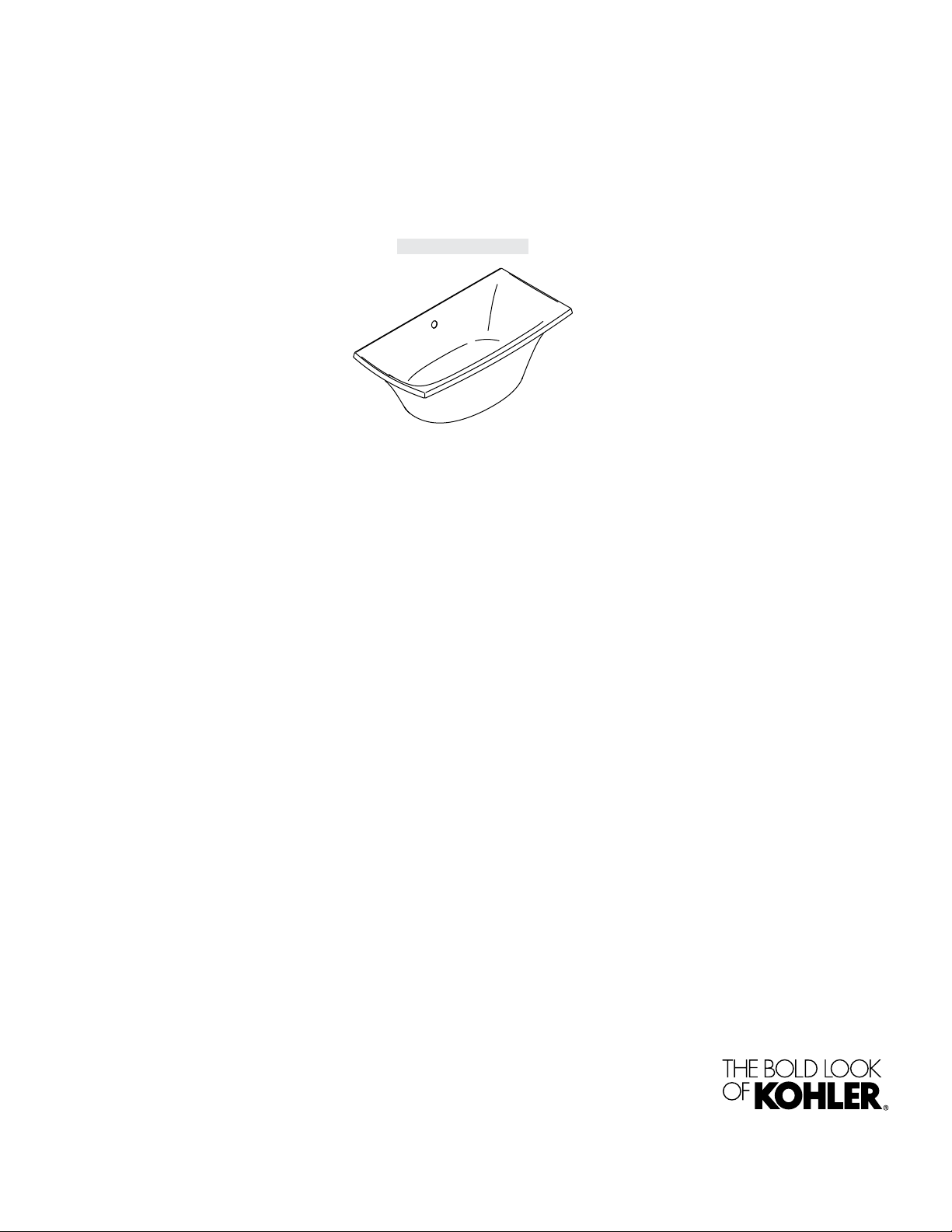
Bath with Airjets
K-11344, K-14037
Retain serial number for reference:
Conserver le numéro de série pour référence:
Guarde el número de serie para referencia:___________
Français, page “Français-1”
Español, página “Español-1”
1220597-2-F

Installation Instructions
WARNING: When using electrical products, basic precautions should always be followed,
including the following:
WARNING: Risk of electric shock. Connect only to a circuit protected by a Ground-Fault
Circuit-Interrupter (GFCI)*.
Install to permit access for servicing.
A pressure wire connector marked ″Earth/Ground″ is provided within the wiring compartment. To reduce
the risk of electric shock, connect this connector to the grounding terminal of your electric service or supply
panel with copper wire equivalent in size to the circuit conductor supplying this equipment.
Pressure wire connectors are provided on the exterior of the junction box or control within this unit to permit
connection of a bonding conductor between this unit and all other exposed metal in the vicinity, as needed to
comply with local requirements.
An equipment grounding terminal is provided in the field wiring compartment. To reduce the risk of electric
shock, this terminal must be connected to the grounding means provided in the electric supply panel with a
conductor equivalent in size to the circuit conductors supplying this equipment.
Grounding is required. The unit should be installed by a qualified service representative, and grounded.
WARNING: Risk of injury or property damage. Please read all instructions thoroughly before
beginning installation.
WARNING: Risk of electric shock. A qualified electrician should make all electrical connections.
WARNING: Risk of electric shock. Disconnect power before servicing.
NOTICE: Follow all local plumbing and electrical codes. In Canada, install this unit in accordance with
the Canadian Electrical Code, Part 1.
*Outside North America, this device may be known as a Residual Current Device (RCD).
Product Information
Electrical Requirements
The installation must have a Class A Ground-Fault Circuit-Interrupter (GFCI) or Residual Current Device
(RCD). The GFCI or RCD protects against line-to-ground shock hazards. Use a 120 V, 15A, 50/60 Hz
dedicated service for the bath with airjets.
The electrical rating of the bath is printed on a label near the blower motor. You can also find the electrical
requirements from the Installation Guide packed with the bath in the Product Information section.
If the blower supply cord is damaged, it must be replaced by the manufacturer, its service agent or similarly
qualified persons in order to avoid a hazard.
Product Notices
WARNING: Risk of personal injury or property damage. Unauthorized modification may cause
unsafe operation or affect performance of the bath. Do not relocate the blower motor, or make other
modifications to the bath system in the absence of kit or other published instructions, as this could
adversely affect the performance and safe operation of the product. Kohler Co. shall not be liable
under its warranty or otherwise for personal injury or damage caused by any such unauthorized
modification. Refer to the ″Install the Blower Motor″ section for blower motor relocation
requirements, recommendations, and installation information.
NOTICE: This product contains an automatic water purge mode that turns the blower on for 2 minutes
approximately 30 minutes after the unit is turned off and drained.
1220597-2-F 2 Kohler Co.

Product Information (cont.)
NOTICE: Keep the area around the blower motor clean and free of sawdust, insulation, dirt, or other
small loose debris. Such material could plug the blower motor air intake and reduce the air flow through
the blower.
Connections and Service Access
Before installation, ensure proper access to the final connections.
NOTICE: Provide generous, unrestricted service access to the blower. Before installation, ensure that
there is proper access to the blower motor and final connections. If the blower motor is installed in an
enclosed area, an access panel is required at the blower motor. This panel should be 18″ (457 mm) wide
and 14″ (356 mm) high minimum.
Features
Factory assembled components include a blower motor, air harness, control, check valve, butterfly valves,
chromatherapy lights (certain models), electrical harnesses, and an illuminated user keypad. Other than
power wiring and plumbing connections, no assembly is required.
Tools and Materials
Plus:
• Conventional tools and materials
• Drop cloth
• Fasteners (as necessary)
• Rags
• Saw horses
100% Silicone
Sealant
• Hole saw
Before You Begin
Blower Information
NOTICE: Relocate the blower motor and check valve together. Do not relocate one without the other.
All material needed for the relocation of the blower motor must be supplied by the installer.
Additional tools and materials you will need to relocate the blower motor:
•
Electrician pliers
•
Assorted screwdrivers
•
Adjustable wrench
•
Drill and bits to install the blower mounting fasteners
•
18 AWG non-metallic sheathed cable, two conductors with ground, with support clips, as required
•
One 4″ (102 mm) x 2″ (51 mm) electrical junction box with cover, gasket, and mounting screws
Kohler Co. 3 1220597-2-F

Before You Begin (cont.)
•
Three strain reliefs - one must fit the blower motor cover with standard National Pipe Thread (NPT)
threads. The other two must fit the holes in the new junction box.
•
Six wire connectors (wire nuts or equivalent)
•
1-1/2″ PVC or other rigid or flexible pipe with fittings, unions, PVC cement (or equivalent fastening
method), and support clips, as required
•
Four fasteners (such as flathead wood screws or concrete anchors) to secure the blower motor
•
Solid copper 8-gauge bonding wire, 36″ (914 mm)
Bath Information
IMPORTANT! To ensure a successful installation, install the bath on a level finished floor.
IMPORTANT! This product requires a K-7219 drain for proper installation.
•
Observe all local plumbing and building codes.
•
Unpack and inspect the bath for damage. Return the bath to the carton until installation.
•
Make sure that all plumbing connections around the bath are easily accessible for future
maintenance.
•
We strongly recommend that a professional plumber or contractor perform this installation.
•
Provide access for making the final drain connection from below.
•
This installation requires a minimum of two people.
•
This bath is designed for a freestanding installation only.
•
Select fasteners and a drilling method based on the type of floor the bath will be attached to.
•
This bath conforms to CSA B45.5/IAPMO Z124. All dimensions are nominal.
Relocate the blower and check valve as close as possible to the bath to maximize performance. Do
not relocate the blower and check valve more than 15’ (4.5 m) from the bath.
Position the blower 1-1/2″ (38 mm) above the floor. Do not mount the blower motor with the
blower motor discharge pointing up.
The blower motor must have adequate ventilation for cooling and air flow. Do not install the blower
motor closer than 1” (25 mm) from the wall or other objects. Provide a free space of about 30 cubic
feet (0.8 cubic meters) for cooling.
The check valve must be relocated with the blower motor. At the new location, the check valve
must be no lower than 24″ (610 mm) below the rim of the bath. The check valve must be within 12″
(305 mm) of the blower motor. The check valve must be oriented vertically with the flow arrow
pointing up. DO NOT relocate the control unit. The control unit must remain with the unit.
Use 1-1/2″ PVC or equivalent piping.
The piping installation must meet the requirements of local plumbing or building codes. Ensure that
the installation does not reduce the fire rating of any walls. Piping must be supported at intervals
along the length in accordance with local codes.
Ensure that the blower motor location is clean and free of dust or debris.
Install an access panel for blower motor maintenance.
The 18 AWG minimum power cable to the blower motor must meet the requirements of all
applicable electrical or building codes. Ensure that the installation does not reduce the fire rating of
any walls.
The power cord must be supported at intervals along its length in accordance with local codes.
Power cords must not rest on surfaces or floors that are subject to flooding.
1. Prepare the Site
NOTICE: Provide adequate floor support.
1220597-2-F 4 Kohler Co.

Prepare the Site (cont.)
NOTICE: Measure your product for site preparation. Note the model number located on the blower end
of the bath, then visit the product page at www.kohler.com for more information.
Ensure the subfloor is level.
Determine the location of the bath. Provide a minimum clearance of 24″ (610 mm) around the
perimeter of the bath. Additional space is recommended to ease installation.
Use the cut-out template provided with the bath to properly mark the water supply and drain
locations in relation to the chosen location of the bath.
Install an access panel to service the remote blower motor.
Prepare the routing paths for 1-1/2″ PVC piping and a keypad cable to run under the floor from the
blower to the bath. Follow all applicable building, fire, plumbing, and electrical codes.
Determine the location on the floor where the PVC piping from the blower will exit from under the
floor to connect to the bath piping. Mark this location on the floor.
Cut the marked water supply and drain locations in the subfloor with a saw and hole saw.
Cut the hole for the blower PVC piping and keypad cable at the marked location on the floor.
Install the rough water supply and drain lines.
Install the finished flooring material prior to installing the bath.
Ensure the finished floor is level before proceeding with the bath installation.
Kohler Co. 5 1220597-2-F

Bath
Frame
Finished Floor
Gasket
1-1/2"
(38 mm)
2. Prepare the Drain Location
IMPORTANT! For installation on a concrete floor, clearance for the drain assembly must be provided.
Refer to the template provided with the bath.
Provide access for making the final drain connection from below.
Verify adequate drain clearance so the bath will install properly.
1220597-2-F 6 Kohler Co.
x4
Tape
Shroud
Screw
Bath
Saw Horse
Foot Clip
Locked
Position
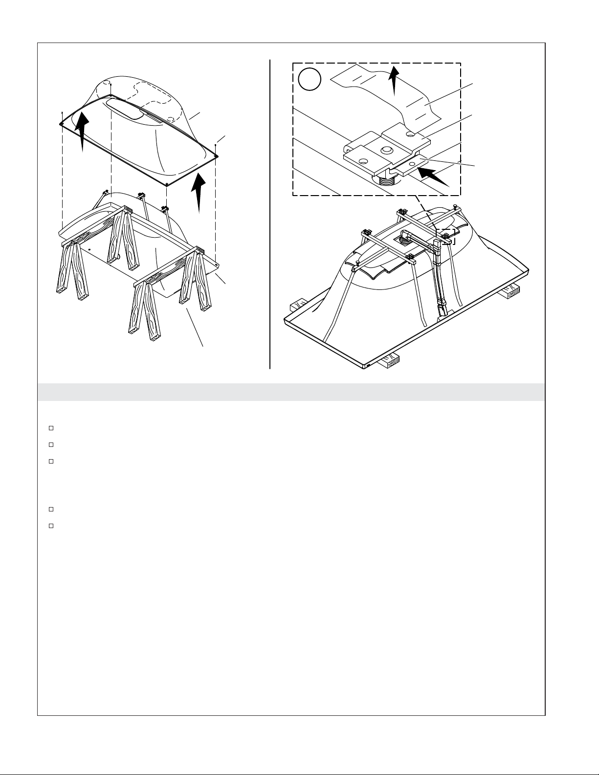
3. Prepare the Bath
IMPORTANT! Do not remove the bath feet or levelers from the bath.
Position the bath upside down on saw horses.
Remove and retain the screw from each corner of the bath shell.
Lift the shroud off the bath shell and set it aside.
IMPORTANT! For installation on a concrete floor, clearance for the drain assembly must be provided.
Refer to the template provided with the bath.
Install the bath drain to the bath according to the instructions included with the drain.
Remove the tape from the four foot clips. Make sure the locking plates are in the locked position
and are oriented toward the outside of the bath as illustrated.
Kohler Co. 7 1220597-2-F

Drain
Overflow
Finished Floor
Drain Pipe
Bath
Front
Locking Plate
with Hole
4. Position Two Foot Clips (Without Shroud)
Turn the bath shell over and set it in position on the finished floor. Make sure the drain lines up
with the drain pipe and there is no drain interference with the floor.
Position each locking plate with the hole to the outside of the bath.
Trace around the edges of the two foot clips located at the front of the bath, opposite the overflow.
Lift the bath and turn it upside down on saw horses.
1220597-2-F 8 Kohler Co.
Unlocked
Position
Foot Clip
Finished Floor
Subfloor
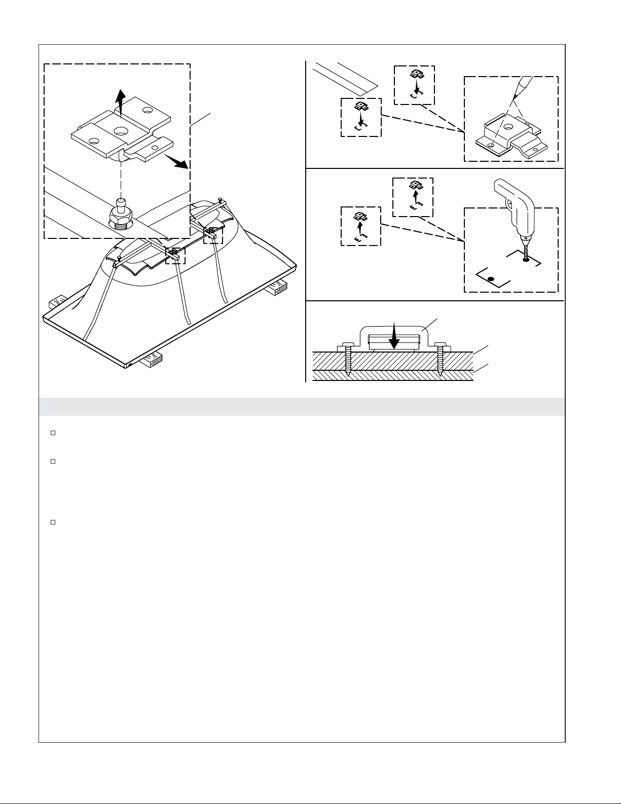
5. Secure Two Foot Clips (Without Shroud)
Pull out the locking plates on the two foot clips that were traced on the floor and remove the foot
clips.
Position these foot clips on the traced lines and mark the four screw holes.
IMPORTANT! Make sure the foot clips will be flush with the finished floor after installation. If you use
anchors that protrude above the finished floor, recess the finished floor material around the holes or recess
the anchors so the foot clips are flat against the finished floor.
Carefully drill the four screw hole locations in the finished floor, and secure the foot clips to the
floor using fasteners suitable for the floor material.
Kohler Co. 9 1220597-2-F
Unlocked
Position
Bath
Front
6. Secure Remaining Foot Clips (Without Shroud)
Reposition the bath so the two posts located on the bath frame fit into the installed foot clips. Do
not move the locking plates into the locked position on the two foot clips mounted to the floor.
Make sure the locking plate screw hole faces the outside of the bath on each of the two remaining
foot clips.
Trace the outline of the two remaining foot clips.
Lift the bath and set it aside.
Repeat the previous steps to remove, mark, drill, and secure the two remaining foot clips.
1220597-2-F 10 Kohler Co.
Blower Motor
Mounting Screws
1-1/2" Rigid Piping
(not supplied)
Check Valve
1-1/2" (38 mm) Min
Screw
Screw
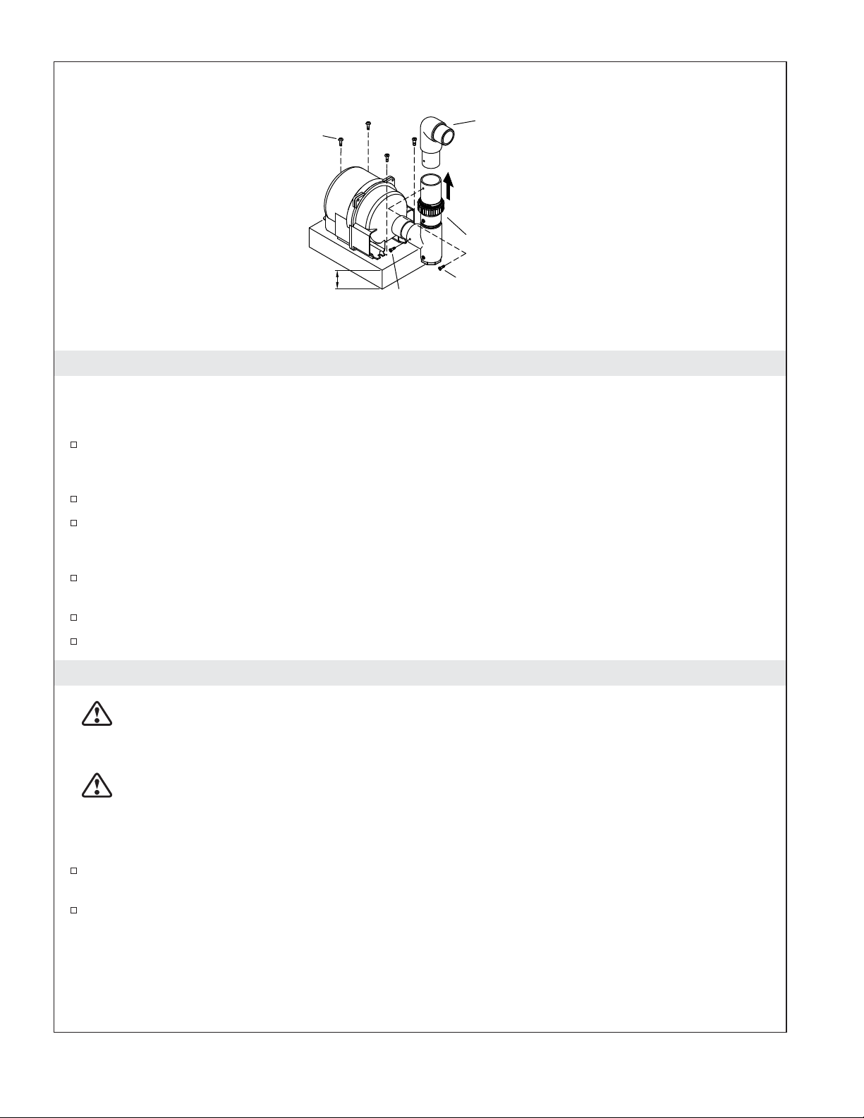
7. Install the Blower Motor
NOTE: Refer to the ″Before You Begin″ section for other detailed requirements for the blower motor
relocation.
At the chosen blower motor location, install a 1-1/2″ (38 mm) high block (not supplied) above the
floor to support the blower motor. Select a block of sufficient length and width to support the entire
blower motor.
Fasten the blower motor to the support block with appropriate fasteners (not supplied).
Install the check valve at the blower motor location. The check valve must be oriented vertically.
Confirm the check valve is oriented with the flow arrow pointing away from the blower motor, and
that it is located no lower than 24″ (610 mm) below the bath rim.
Install and support 1-1/2″ PVC piping (not supplied) under the floor between the blower motor and
the bath location. Do not connect the PVC piping at either end until instructed.
At the bath, cement a union or other serviceable connection to the coiled blower hose.
Confirm all wall holes are properly sealed and comply to local building and fire codes.
8. Make Electrical Connections - USA and Mexico
WARNING: Risk of electric shock. Connect the blower motor to a properly grounded,
grounding-type receptacle protected by a Ground-Fault Circuit-Interrupter (GFCI) or Residual
Current Device (RCD). Do not remove the grounding pin from the plug. Do not use a grounding
adapter.
WARNING: Risk of electric shock. Disconnect the power before performing the following
procedures.
NOTICE: The blower motor is equipped with a cord and plug. A qualified electrician must install a GFCIor RCD-protected, 120 V, 15 A, grounded outlet for the blower. No other load should be on this circuit.
Install an electrical outlet behind the bath, at least 1-1/2″ (38 mm) above the subfloor, and within
reach of the 24″ (610 mm) power cord.
Plug the blower into the outlet.
Kohler Co. 11 1220597-2-F
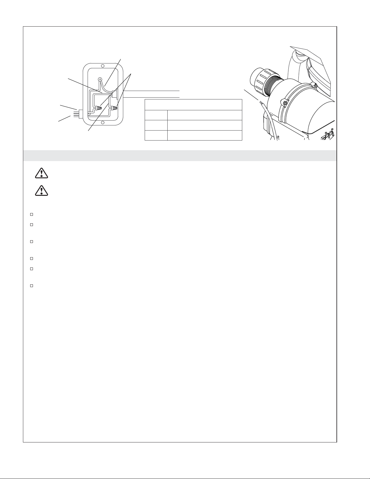
The junction box should be
wired as shown.
Bond in accordance with
national and local codes.
Ground (Green with Yellow Stripe)
Line (Black)
Electrician to
Wire Connectors
From Blower Motor
Blower Motor
Electrical Cord
provide suitable
strain relief.
Supply
Neutral (White)
From Blower Motor
L1
GND
Black
N White
Green with Yellow Stripe
9. Make the Electrical Connections – Canada
WARNING: Risk of electric shock. Make sure the power has been disconnected before performing
the following procedures.
WARNING: Risk of electric shock. Connect the blower motor to a properly grounded,
grounding-type Ground-Fault Circuit-Interrupter (GFCI) or Residual Current Device (RCD). This
will provide additional protection against line-to-ground shock hazard.
Locate and secure each supplied junction box a minimum of 1-1/2″ (38 mm) above the subfloor.
The bath controls and system have been prewired at the factory. A qualified electrician should make
a routine service connection to the junction box.
Connect service to the junction box. The 60 Hz model junction box contains black and white wires
and a ground lug.
A 120 V, 15 A dedicated circuit is required. Provide a Class A GFCI or RCD.
Provide a separate equipment grounding conductor for the inside ground or ground lug. The
conductor must not be connected to any current-carrying conductor.
Bond in accordance with national and local codes.
1220597-2-F 12 Kohler Co.
x4
100% Silicone
Sealant
x4
Post
x2
Bath
Leveler
x4
24-1/8"
(613 mm)
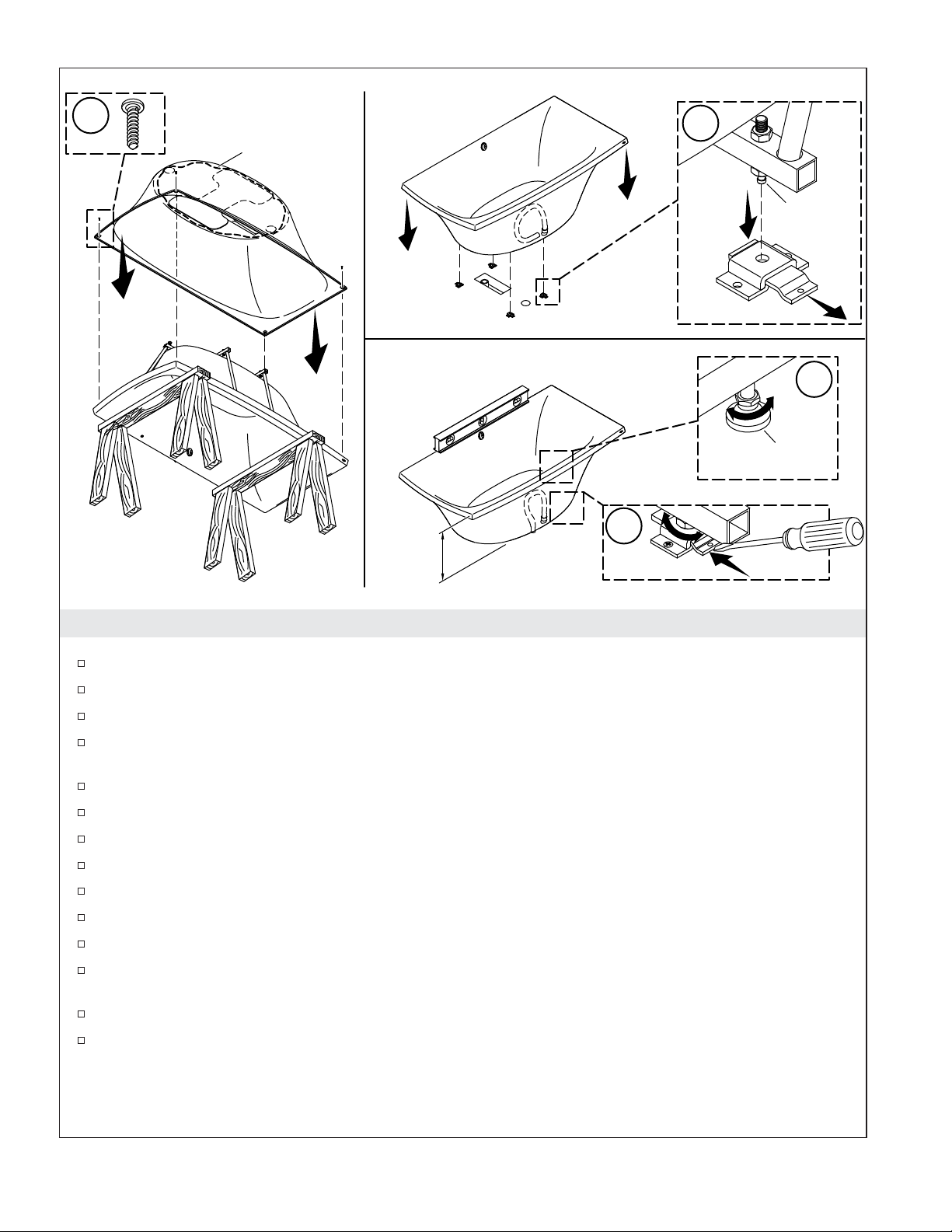
10. Install the Bath
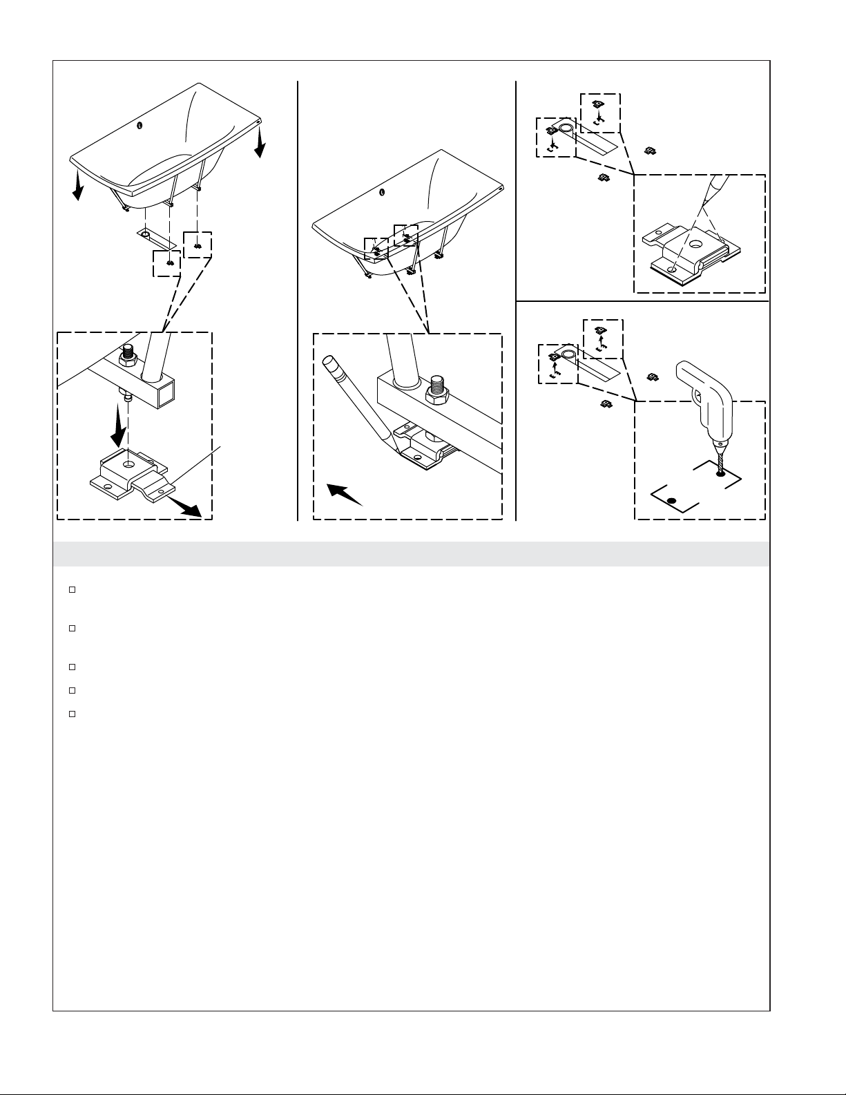
Turn the bath shell upside down on the saw horses.
Make sure that all the drain connections are secure.
Cut the cable ties securing the PVC blower hose and keypad cable.
Position the shroud on the bath so the edges of the shroud rest inside the bath shell. Make sure that
the blower hose and keypad cable are accessible from the bottom of the shroud.
Secure the shroud to the bath with a screw at each corner. Do not overtighten.
Apply a bead of 100% silicone sealant around the perimeter of the bottom of the shroud.
Make sure that the foot clips are not in the locked position.
Move the bath close to the installation location.
Cement the PVC blower hose connection to the PVC piping.
Route the keypad cable under the floor and to the blower motor area.
Carefully set the bath into position while feeding the PVC pipe into the hole in the floor.
Make sure that the posts on the bath frame fit into the four foot clips, and that the drain fits into the
drain pipe.
Check for solid fit (no rocking) and a 24-1/8″ (613 mm) rim corner height to the finished floor.
If necessary, lift the bath and adjust the four posts as needed to ensure a distance of 24-1/8″ (613
mm) from the finished floor to the top of each bath rim corner. Adjust the bath levelers as needed.
Make sure that the bath levelers and bath feet are tight.
Kohler Co. 13 1220597-2-F
Install the Bath (cont.)
Press down on the bath corners with your hand to make sure that the bath does not move up and
down, or side to side. If the bath moves check that all four posts are inside the foot clips, and check
that the floor is level.
Use a flat-blade screwdriver to push in the four locking plates to lock the bath feet in place.
At the blower end, cut off any excess PVC piping and connect the PVC pipe to the blower pipe.
Connect the keypad cable to the blower motor.
11. Complete the Installation
Finish the Installation
Install the faucet trim.
Make the final drain connection.
Test Run the Bath
Fill the bath to a level at least 4″ (102 mm) above the top of the highest airjet.
Operate the bath for 5 minutes and check all bath piping connections for leaks. Check for leakage
along the front, sides, and back of the bath.
Clean-up After Installation
When cleaning up after installation, do not use abrasive cleansers, as they may scratch and dull the
bath surface. Use warm water and a liquid detergent to clean the surface of the bath.
Important Safety Instructions
READ AND FOLLOW ALL INSTRUCTIONS
SAVE THESE INSTRUCTIONS
INSTRUCTIONS PERTAINING TO A RISK OF FIRE, ELECTRIC SHOCK, OR INJURY TO PERSONS
WARNING: When using electrical products, basic precautions should always be followed,
including the following:
DANGER: Risk of accidental injury or drowning. To reduce the risk of injury, do not permit
children to use this unit unless they are closely supervised at all times.
WARNING: Risk of personal injury. To avoid injury, exercise care when entering or exiting the
bath.
WARNING: Risk of electric shock. Do not permit electric appliances (such as a hair dryer, lamp,
telephone, radio, or television) within 5’ (1.5 m) of this bath.
WARNING: The use of alcohol, drugs, or medication can greatly increase the risk of fatal
hyperthermia. Prolonged immersion in hot water may induce hyperthermia. Hyperthermia occurs
when the internal temperature of the body reaches a level several degrees above the normal body
temperature of 98.6°F (37°C). The symptoms of hyperthermia include an increase in the internal
temperature of the body, dizziness, lethargy, drowsiness, and fainting. The effects of hyperthermia
include: (a) failure to perceive heat, (b) failure to recognize the need to exit the bath, (c)
unawareness of impending hazard, (d) fetal damage in pregnant women, (e) physical inability to
exit the bath, and (f) unconsciousness resulting in the danger of drowning.
1220597-2-F 14 Kohler Co.
Important Safety Instructions (cont.)
WARNING: Risk of fetal injury. Pregnant or possibly pregnant women should consult a physician
before using the bath.
WARNING: Risk of hyperthermia or drowning. Do not use the bath immediately following
strenuous exercise.
WARNING: Risk of hyperthermia or drowning. Water temperature in excess of 100°F (38°C) may
cause injury. Test and adjust the water temperature before use.
WARNING: Risk of personal injury. Never drop or insert any object into any opening.
Use this bath only for its intended purpose as described in this guide. Do not use attachments not
recommended by Kohler Co.
The bath must be connected only to a supply circuit that is protected by a Ground-Fault Circuit-Interrupter
(GFCI)*. Such a GFCI should be provided by the installer and should be tested on a routine basis. To test the
GFCI, press the test button. The GFCI should interrupt power. Press the reset button. Power should be
restored. If the GFCI fails to operate in this manner, the GFCI is defective. If the GFCI interrupts power to
the bath without the test button being pressed, a ground current is flowing, indicating the possibility of an
electric shock. Do not use this bath. Disconnect the bath and have the problem corrected by a qualified
service representative before using.
Flush your whirlpool system twice a month or more depending upon usage, as described in the ″Flush the
System″ section of this guide.
Repeated use of personal care products containing oils can damage plastic whirlpool components. Avoid
using bath oils.
Whirlpool hydro-massage action can cause even a small amount of bubble bath, bath soap, shampoo, or bath
oil to foam excessively. For this reason, please do not use these products during whirlpool operation.
* Outside North America, this device may be known as a Residual Current Device (RCD).
Kohler Co. 15 1220597-2-F
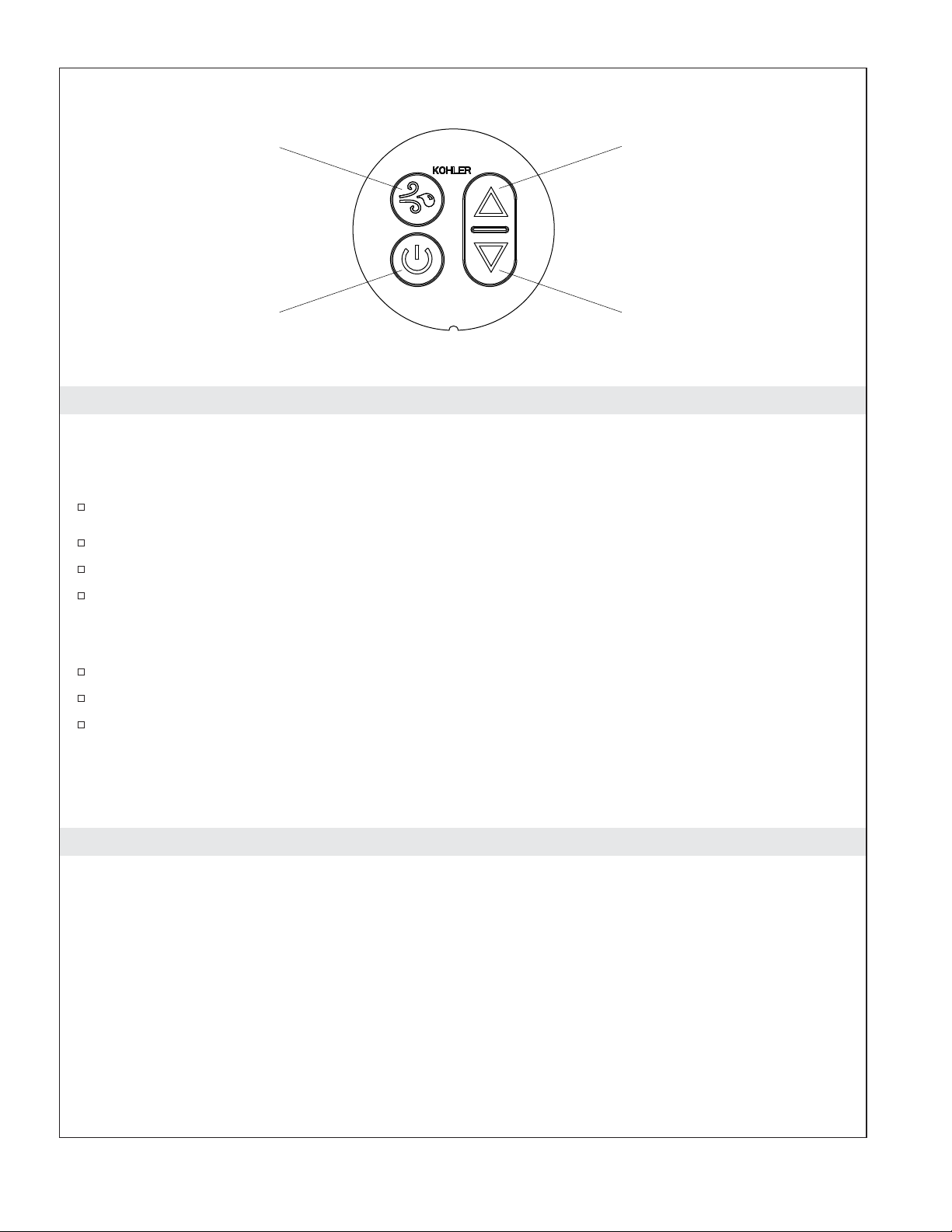
Purge Mode
Increases Flow
On/Off
Decreases Flow
Operating Instructions
IMPORTANT! This product contains an automatic water purge mode that turns the blower on for 2
minutes approximately 30 minutes after the unit is turned off and drained.
NOTE: The water temperature in the bath should never exceed 104°F (40°C).
Close the drain, then fill the bath at least 4” (102 mm) above the top of the highest airjet.
Use your hand to test the water temperature for comfort and safety, then carefully enter the bath.
Press the [On/Off] icon to turn the blower on at medium speed.
Press the [Up] or [Down] arrow icons to increase or decrease the air flow.
NOTE: The blower will turn off automatically following 20 minutes of operation, and can be immediately
restarted if desired.
Press the [On/Off] icon a second time to turn off the blower.
Carefully exit and drain the bath.
Press the [Purge Mode] icon to blow remaining water from the air channels. The blower will turn
on for 2 minutes and then turn off automatically.
NOTE: About 30 minutes after the blower motor stops, a 2 minute purge mode will automatically start.
NOTE: If the bath does not function properly, refer to the ″Troubleshooting″ section.
Care and Cleaning
For best results, keep the following in mind when caring for your KOHLER bath with airjets:
•
Always test your cleaning solution on an inconspicuous area before applying to the entire surface.
•
Wipe surfaces clean and rinse completely with water immediately after applying cleaner. Rinse and
dry any overspray that lands on nearby surfaces.
•
Do not allow cleaners to soak on surfaces.
•
Use a soft, dampened sponge or cloth. Never use an abrasive material such as a brush or scouring
pad to clean surfaces.
•
The ideal cleaning technique is to rinse thoroughly and blot dry any water from the surface after
each use.
•
Use a soft nylon brush on slip-resistant surfaces. Be sure to use a water-soluble cleaner (dissolves
100% in water).
•
Do not use powdered cleaners unless the cleaner is fully dissolved in water. Solid substances can
block the airjets.
1220597-2-F 16 Kohler Co.

Care and Cleaning (cont.)
•
Do not use full strength bleach or ammonia cleaning solutions. Chemically active cleaning
solutions can damage the surface.
•
Do not use abrasive cleansers or solvents on airjet surfaces. Abrasive cleaners and solvents can
damage the airjet surface.
Maintaining the Airjets
If cleaning the airjets is necessary due to hard water deposits, wet a soft, non-abrasive cloth with
white vinegar and wipe the plugged airjet holes. Immediately rinse the area with clean water to
avoid long-term exposure of the vinegar to the airjet surface.
Fill the bath with water to the top row of airjets. Drain the bath and press the purge button.
Cleaning Your User Keypad and Remote Control
Use a soft cloth to wipe the keypad and remote control after each use. If the surface becomes dirty,
use a non-abrasive soap and warm water to clean.
For detailed cleaning information and products to consider, visit www.kohler.com/clean. To order Care &
Cleaning information, call 1-800-456-4537.
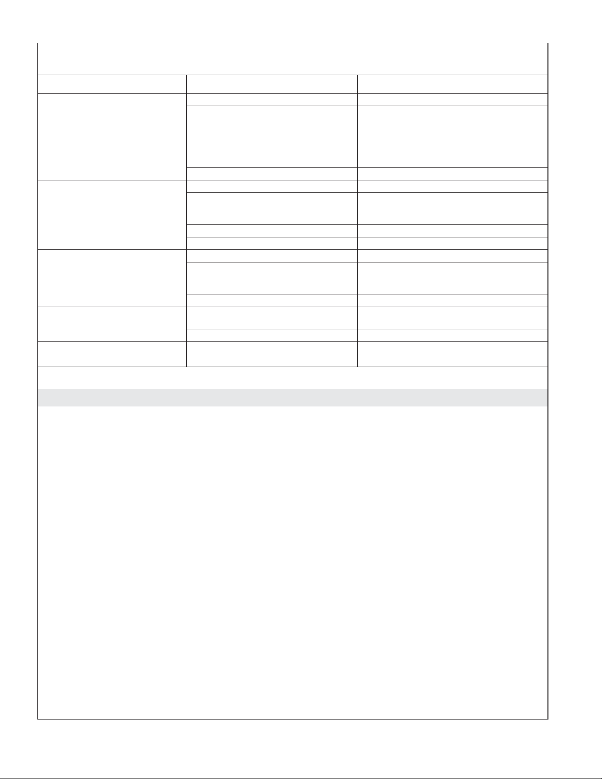
Troubleshooting
NOTICE: This section is for general aid only. A Kohler Co. Authorized Service Representative (ASR) or
qualified electrician should correct any electrical problems. For warranty service, call 1-800-4KOHLER from
within the USA and Canada, or 001-800-456-4537 from within Mexico.
NOTE: The product model number is printed on a label on the blower side of the bath.
NOTE: For service parts information, visit your product page at kohler.com/serviceparts.
Symptoms Probable Causes Recommended Action
1. Blower turns on by itself
after the bath has been
drained.
2. Blower turns off by itself
after running for 2
minutes.
3. Blower motor will not
start.
4. Blower motor stops
running and will not
immediately restart.
5. Blower motor starts, some
but not all airjets are
working.
A. Normal operation. Automatic
purge mode is working as
designed.
A. The Purge Mode icon was
pressed instead of the On/Off
icon.
A. Power cord from blower motor
is loose, disconnected, or
damaged.
B. User keypad cable loose or
damaged.
C. User keypad does not work. C. Replace user keypad.
D. Blower motor does not work. D. Replace the blower motor.
A. Blower motor overheated and
protection device activated.
A. Blower motor speed is too low. A. Increase speed.
B. Blower motor inlet is blocked. B. Clean blower motor inlet.
C. Blower motor does not work. C. Replace the blower motor.
D. Blower motor discharge is
blocked.
E. Airjets are clogged. E. Use a small between-the-teeth
A. No action is required. Automatic
purge mode runs for 2 minutes 30
minutes after the bath is drained.
A. Press the On/Off icon on the
keypad. See the ″Operating
Instructions″ section.
A. Check wiring for proper
connections.
B. Check wire connections. If
necessary, replace user keypad
cable.
A. Check for blockage at blower air
intake. Remove blockage and allow
motor to cool.
D. Clear blockage.
dental brush and white vinegar.
Dip the brush in the vinegar, brush
the hole, rinse the brush in clean
water, and then use the wet rinsed
brush to rinse the hole.
Kohler Co. 17 1220597-2-F
Troubleshooting (cont.)
Symptoms Probable Causes Recommended Action
6. Blower motor runs but no
air bubbles are observed.
7. Blower motor operates,
air bubbles are observed,
but speed feature does
not work.
8. Blower motor does not
turn off when the On/Off
button is pressed.
9. Purge mode does not
work.
10. Bath does not purge
automatically.
A. Blower motor inlet is blocked. A. Clean blower motor inlet.
B. Airjets are clogged. B. Use a small between-the-teeth
C. Blower motor does not work. C. Replace the blower motor.
A. Blower motor inlet is blocked. A. Clean blower motor inlet.
B. Loose, disconnected, or
damaged wiring harness.
C. User keypad does not work. C. Replace the user keypad.
D. Blower motor does not work. D. Replace the blower motor.
A. User keypad does not work. A. Replace the user keypad.
B. Loose, disconnected, or
damaged wiring harness.
C. Control does not work. C. Replace the control.
A. User keypad does not work. A. Replace the user keypad.
B. Control does not work. B. Replace the control.
A. Blower does not work. A. Replace the blower.
dental brush and white vinegar.
Dip the brush in the vinegar, brush
the hole, rinse the brush in clean
water, and then use the wet rinsed
brush to rinse the hole.
B. Check wiring for proper
connections. Replace the wiring
harness if necessary.
B. Check wiring for proper
connections. Replace the wiring
harness if necessary.
Warranty
ONE-YEAR LIMITED WARRANTY
KOHLER plumbing products are warranted to be free of defects in material and workmanship for one year
from date of installation.
Kohler Co. will, at its election, repair, replace or make appropriate adjustment where Kohler Co. inspection
discloses any such defects occurring in normal usage within one (1) year after installation. Kohler Co. is not
responsible for removal or installation costs. Use of in-tank toilet cleaners will void the warranty.
To obtain warranty service contact Kohler Co. either through your Dealer, Plumbing Contractor, Home
Center or E-tailer, or by writing Kohler Co., Attn.: Customer Care Center, 444 Highland Drive, Kohler, WI
53044, USA, or by calling 1-800-4-KOHLER (1-800-456-4537) from within the USA and Canada, and
001-800-456-4537 from within Mexico, or visit www.kohler.com within the USA, www.ca.kohler.com from
within Canada, or www.mx.kohler.com in Mexico.
IMPLIED WARRANTIES INCLUDING THAT OF MERCHANTABILITY AND FITNESS FOR A
PARTICULAR PURPOSE ARE EXPRESSLY LIMITED IN DURATION TO THE DURATION OF THIS
WARRANTY. KOHLER CO. AND/OR SELLER DISCLAIM ANY LIABILITY FOR SPECIAL,
INCIDENTAL OR CONSEQUENTIAL DAMAGES. Some states/provinces do not allow limitations on how
long an implied warranty lasts, or the exclusion or limitation of special, incidental or consequential damages,
so these limitations and exclusions may not apply to you. This warranty gives you specific legal rights. You
may also have other rights which vary from state/province to state/province.
This is Kohler Co.’s exclusive written warranty.
1220597-2-F 18 Kohler Co.
 Loading...