

Page 1
BUILT IN DUAL CONTROL
SHOWER VALVE
Installation and User Guide
These instructions are to be left with the user
1
Page 2

CONTENTS
Introduction ............................................................................................. 3
Safety : Warnings .................................................................................... 3
Pack Contents ......................................................................................... 4
Dimensions ............................................................................................. 5
Specifications ..........................................................................................6
Pressures ............................................................................................ 6
Temperatures ....................................................................................... 6
Flow Rates ...........................................................................................6
Connections ......................................................................................... 7
Installation Requirements ...................................................................... 8
Installation ............................................................................................. 10
General .............................................................................................. 10
Installation Methods ........................................................................... 11
1. Solid Wall or Stud Partition
(Using Securing Brackets - Mounting off Front Face) ................. 12
2. Solid Wall or Stud Partition
(Using Rear Fixing Points on Shower Control) ............................ 15
3. Laminated Panel
(Using Securing Brackets - Mounting off Rear Face) .................. 17
Control Assembly .............................................................................. 19
Reversed Supplies ............................................................................. 21
Commissioning ..................................................................................... 22
Maximum Temperature Setting .......................................................... 22
Operation ............................................................................................... 23
Fault Diagnosis ..................................................................................... 24
Maintenance .......................................................................................... 25
General .............................................................................................. 25
Lubricants .......................................................................................... 25
Cleaning ............................................................................................. 25
Filters ................................................................................................ 25
Spare Parts ............................................................................................ 26
Customer Service .................................................................... Back Page
2
Page 3

INTRODUCTION
The Mira Discovery Built in Dual Control Shower Valve is a thermostatic shower control
with independent selection for temperature and spray force and is suitable for
connection to concealed pipework.
SAFETY : WARNINGS
This Discovery Thermostatic Shower Control is precision engineered and should give
continued safe and controlled performance, provided:
1. It is installed, commissioned, operated and maintained in accordance with
manufacturers recommendations.
2. Periodic attention is given, when necessary, to maintain the product in good
functional order.
The function of a thermostatic mixing valve is to deliver water consistently at a safe
temperature. In keeping with every other mechanism, it cannot be considered as
functionally infallible and as such, cannot totally replace a supervisor’s vigilance where
that is necessary. Provided it is installed, commissioned, operated and maintained
within manufacturers recommendations, the risk of failure, if not eliminated, is reduced
to the minimum achievable.
If you experience any difficulty with the installation or operation of your new shower
control, then please refer to "Fault Diagnosis", before contacting Kohler Mira Limited.
Our telephone and fax numbers can be found on the back cover of this guide.
3
Page 4

PACK CONTENTS
Tick the appropriate boxes to familiarize yourself with the Discovery Thermostatic
Shower Control part names and to confirm that the parts are included.
1 x Control Assembly
1 x Shower Valve fitted to the Building-in Shroud
3 x Compression Nuts
1 x O-Key
3 x Olives
1 x Hose Washer
x Flow
Regulator
(12 litres per minute)
1 x Hexagon Key
3 x Mounting Brackets
3 x Wall Plugs
3 x Securing Screws
2 x M5 x 40 Screws
3 x M5 x 8 Screws
1 x Customer Support Card
4
Page 5

DIMENSIONS
186 mm
108 mm
Pipe Centres
Note! All Dimensions are Nominal
47 mm 64 - 82 mm
27 mm
231 mm
5
Page 6
SPECIFICATIONS
Pressures
Maximum Static Pressure: 10 Bar.
Minimum Maintained Pressure (Gas Water Heater): 1.0 Bar.
(for optimum performance initial supplies should be nominally equal).
Minimum Maintained Pressure (Gravity System): 0.1 Bar.
(0.1 bar = 1 Metre head from base of cold tank to the outlet of the shower handset).
Maximum Maintained Pressure: 5 Bar.
Temperatures
Factory Pre-set (Blend) Shower: 43°C.
Optimum Thermostatic Control Range: 35°C - 45°C.
(Achieved with supplies of 15°C cold, 65°C hot and nominally equal pressures).
Max. Hot Supply: 85°C.
Recommended Hot Supply: 60°C - 65°C.
Min. Differential between Hot Supply and Outlet Temperature: 10°C.
Cold Water Range: 1°C - 20°C.
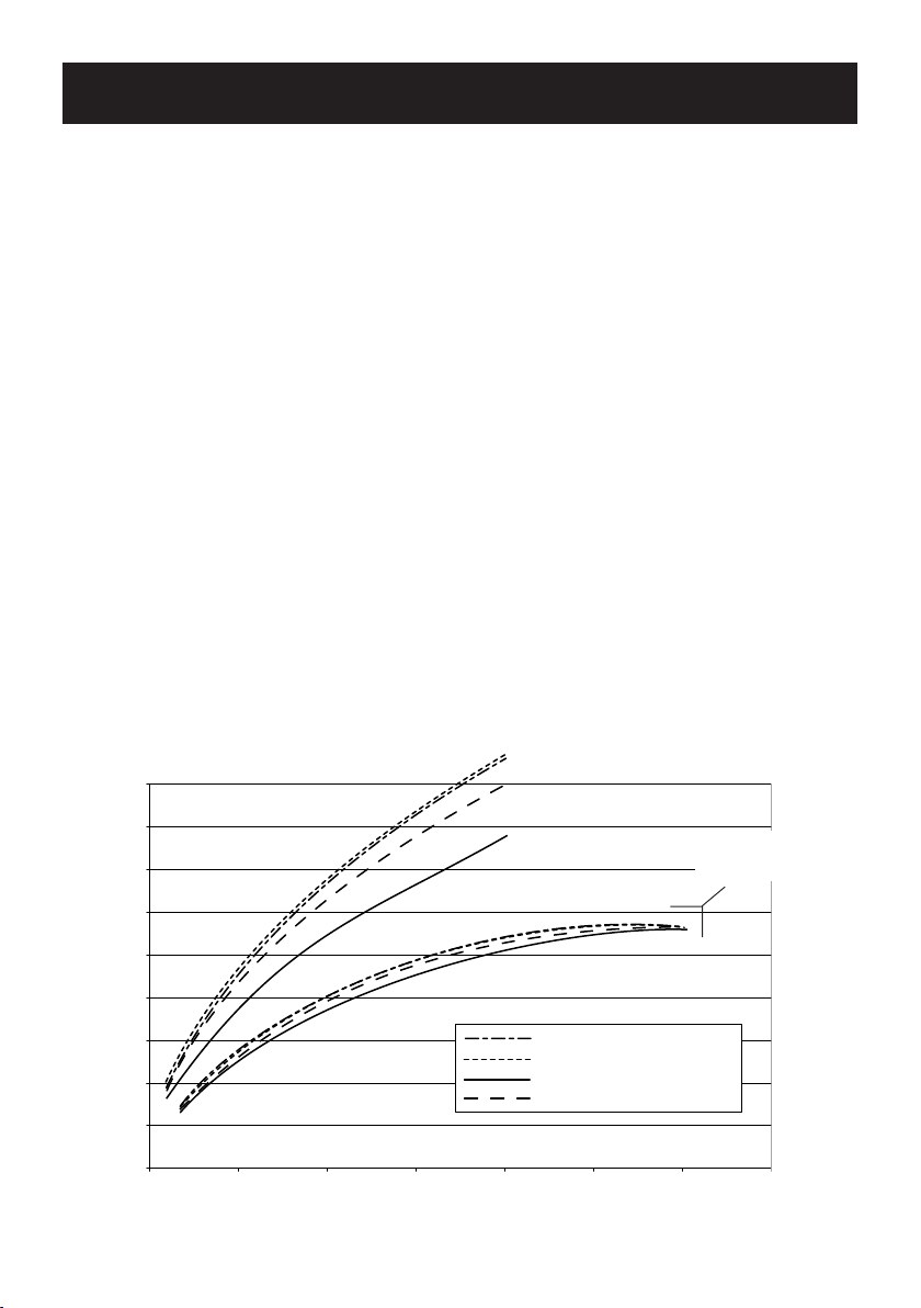
Flow Rates
Typical Flow Rates - Mira Discovery Dual Control with Adjustable Fittings:
18
16
14
12
10
8
Flow Rate (L/Min)
6
4
2
0
0 0.5 1.0 1.5 2.0 2.5 3.0 3.5
Supply Pressure (Bar)
Start (Outer Spray)
Soothe (Middle Spray)
Force (Inner Spray)
Rigid (Fixed Spray)
6
With 12 L/Min Flow
Regulator Fitted
Page 7

Connections
Standard connections are: Hot-Left, Cold-Right, Top-Outlet, if reversed inlets are
required refer to sections: ‘Installation’ and ‘Reversed Supplies’.
Inlets: 15 mm Compression.
Outlet: 15 mm Compression.
Thermostatic Shut-down
Thermostat will shut off Hot Supply Within 2 Seconds if Cold Supply Fails.
(Achieved only if the hot supply temperature is greater than 10°C above the set blend
temperature).
7
Page 8

INSTALLATION REQUIREMENTS
Key to symbols
Isolating valve
Mixing Valve
Overflow Indicator
Pressure Reducing Valve
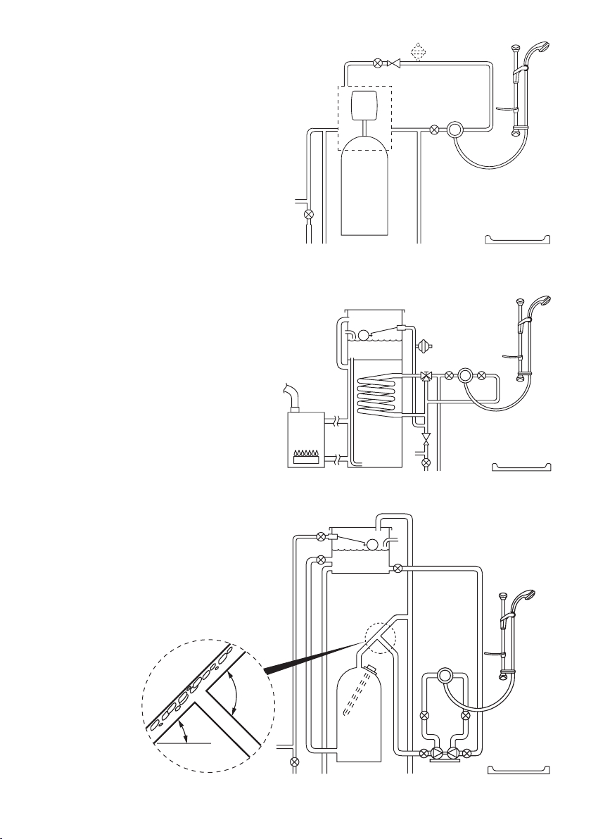
Note! The Shower Control is compatible with the following installations.
Gravity fed system
The shower MUST be fed from a cold
water cistern and hot water cylinder
providing nominally equal pressure.
Twin Impeller Pump
Single Impeller Pump
Tempering Valve
Mini Expansion Vessel
Gas heated system
The shower MUST be installed with a
gas water heater or combination boiler
of a fully modulating design.
Note! Flow regulator recommended to be
installed, refer to the ‘Discovery Fittings
Installation and User Guide’. However,
it is possible following installation of a
flow regulator that the flow rate is reduced
too much for the boiler to ignite. If this is
Flow Regulator Recommended
the case remove the flow regulator.
8
Page 9
Unvented mains pressure system
The shower can be installed with a
unvented, stored hot water cylinder.
Flow Regulator Recommended
Mains pressurised instantaneous
hot water system (thermal store)
The shower can be installed with
systems of this type with balanced
pressures.
Note! Flow regulator recommended to be
installed, refer to the ‘Discovery Fittings
Installation Manual’.
Flow Regulator Recommended
Pumped system
The shower can be installed with an inlet
pump (twin impeller). The pump must be
installed on the floor next to the hot water
cylinder.
Note! Flow regulator recommended to be
installed, refer to the ‘Discovery Fittings
Installation Manual’.
Flow Regulator Recommended
30°-60°
Air Separation
90°
9
Page 10

INSTALLATION
General
Installation must be carried out in accordance with these instructions, and must be
conducted by designated, qualified and competent personnel.
The installation must comply with the “Water Supply Regulations 1999 (Water Fittings)”
or any particular regulations and practices, specified by the local water company or
water undertakers.
Note! Make sure that all site requirements correspond to the information given in the
section: ‘Specifications’.
Caution! The shower must not be installed in an area where it may freeze.
For stud partitions alternative fixings may be required.
1. Isolating valves must be installed close to the valve for ease of maintenance.
2. Pipework must be rigidly supported and avoid any strain on the connections.
3. Pipework dead-legs should be kept to a minimum.
4. Supply pipework layout should be arranged to minimise the effect of other outlet
usage upon the dynamic pressures at the valve inlets.
5. Inlet and outlet threaded joint connections should be made with PTFE tape or
liquid sealant. Do not use oil-based, non-setting joint compounds.
6. To eliminate pipe debris it is essential that supply pipes are thoroughly flushed
through before final connection.
7. Determine the route for the hot and cold supply pipework and for the outlet pipework.
When connecting to the biv shower fittings it is recommended that the outlet be
positioned above and to one side of the shower control. This is to prevent the
flexible hose from obstructing the temperature and flow knobs of the shower
control.
8. Decide on a suitable position for the
shower control. The position of the
shower control and the shower fittings
must provide a minimum gap of
25 mm between the spill-over level of
the shower tray/bath and the handset.
This is to prevent back-siphonage. For
further information on the installation
of your shower fittings, refer to the
Discovery Fittings Installation and User
Guide.
Note! Only use shower fittings
recommended by the manufacturer or
supplier.
Hose Retaining Ring
25 mm Minimum
Spill-over Level
10
Page 11

Installation Methods
The Discovery Thermostatic Shower Control
can be installed using Rear Fixing Points
on the Body, or by using the Securing
Brackets (supplied) on the Front Face of a
Solid Wall or Stud Partition, or on the Rear
Face of a Laminated Panel.
For installation from the front face into a
Solid Wall or Stud Partition using the
Securing Brackets, go to section:
‘Installation, 1. Solid Wall or Stud
Partition (Using Securing Brackets Mounting off Front Face)’.
For installation from the front face into a
Solid Wall or Stud Partition using the Rear
Fixing Points, go to section: ‘Installation,
2. Solid Wall or Stud Partition (Using
Rear Fixing Points on Shower Control)’.
For installation behind a Laminated Panel
using the Securing Brackets, go to section:
‘Installation, 3. Laminated Panel (Using
Securing Brackets - Mounting off Rear
Face)’.
Warning! Bottom bracket not
to be drilled or screwed to.
11
Page 12

1. Solid Wall or Stud Partition (Using Securing Brackets - Mounting off Front Face)
1.1 Remove the three securing screws and
remove the shower valve from the
building-in shroud (retain the screws
for later use).
1.2 Mark the position of the shower valve,
a cut out 150 x 170 mm (Max) is
required.
Note! Use a spirit level to make sure
that the hole cutout will be horizontal
and vertical.
1.3 Mark the routes for the hot and cold
supply pipework at 108 mm centres.
Outlet Pipe BIV Outlet Pipe BIV
Falling Supplies: For falling supplies
remove the grubscrew on each elbow.
Remove the elbows and install on
opposite sides. Secure the elbows with
the grub screws.
Hot Inlet Cold Inlet
Note! Make sure that the filter plugs
are positioned to the front (i.e.
hexagonal key facing forward).
170 mm Max
150 mm Max
Outlet
Pipe BIR
Shower Control
1.4 Mark the route for the outlet pipework.
Note! For biv models the outlet elbow
should be sited above the control and
on the right or left, as site dictates.
1.5 Cut away the plasterboard or brick work
to a minimum depth of 58 mm to
accommodate the shower valve body,
the hot and cold supply pipework and
the outlet pipework.
1.6 Make sure that the building-in shroud
fits inside the hole cutout.
12
6 mm Min
Finished Wall
Finished Wall
24 mm Max
Finished Wall
58 mm Min
Page 13

1.7 Fit the three securing brackets to the
shower valve.
Important! Make sure that the correct
holes are used, otherwise the
backplate will not fit (refer to
illustration).
Note! The brackets can be rotated for
suitable fixing points.
1.8 Mark the positions of the countersunk
fixing holes on the wall.
Note! Make sure that they do not
interfere with the pipework.
1.9 Drill three 6 mm holes for the wall
plugs.
Rotate for Suitable
Fixing Point
Backplate
Securing Holes
1.10 Fit the wall plugs (supplied) and secure
the shower valve to the wall with the
securing screws (supplied).
Note! For stud partition installations
alternative fixings may be required (not
supplied).
Important! At this point position the
building-in shroud onto the shower
valve and make sure that it is
horizontal and will be parallel to the
finished wall surface.
1.11 Remove the building-in shroud and fit
the hot and cold supply pipes and outlet
pipe and tighten the compression nuts.
Caution! Make sure that the olives are
fitted and all pipework is flushed
through before connecting to the
shower valve.
1.12 Fit the outlet pipework, leaving enough
pipe through the wall to temporarily cap
off.
Backplate
Securing Hole
Countersunk
Fixing Hole
Securing
Screw
1.13 Turn on the water supplies and check
for leaks.
Securing
Bracket
13
Page 14

1.14 Re-fit the building-in shroud to the shower valve using the three fixing screws.
1.15 Using the building-in shroud as a guide for the finished wall thickness, finish the
wall.
Caution! Make sure that the finished wall is within the minimum and maximum
limits otherwise the control components will not fit correctly.
1.16 Remove the building-in shroud. Retain the three securing screws for securing the
backplate.
1.17 Fit the shower fittings, refer to your fittings installation and user guide for
instructions.
1.18 Fit the control assembly, refer to section: ‘Control Assembly’.
Spirit Level
Building-in
Shroud
Minimum
Building-in Depth
Securing
Screws
Maximum
Building-in Depth
14
Page 15

2. Solid Wall or Stud Partition (Using Rear Fixing Points on Shower Control)
2.1 Refer to section: ‘1. Solid Wall or
Stud Partition Installation (Using
Securing Brackets - Mounting off
Front Face)’ and follow instructions
1 to 4.
2.2 Cut away the plasterboard or brick work
to the required depth.
Important! This depth ‘X’ will depend
on the finished wall thickness e.g. tiles
or facia board. Refer to the table for
this measurement.
For stud partitions depth ‘X’ refers to
the distance from the rear mounting
e.g. wooden baton, to the front of the
wall (before tiling).
Rear Support
Finished Wall
Surface
Finished Wall
Thickness
Depth ‘X’
Finished Wall Thickness
(e.g. tile and adhesive)
6 mm
8 mm
10 mm
12 mm
14 mm
16 mm
18 mm
20 mm
22 mm
24 mm
Wall Cutout Depth ‘X’
76 - 58 mm
74 - 56 mm
72 - 54 mm
70 - 54 mm
68 - 54 mm
66 - 54 mm
64 - 54 mm
62 - 54 mm
60 - 54 mm
58 - 54 mm
15
Page 16

2.3 Mark the positions of the fixing screw
holes on the wall.
2.4 For solid walls drill two 6 mm holes for
the wall plugs.
2.5 Fit the wall plugs (supplied) and fix the
shower valve to the wall with the
securing screws (supplied).
Note! For stud partition installations
alternative fixings may be required (not
supplied) to fix the shower valve to the
rear face of the wall cavity or to a
timber noggin.
Important! At this point position the
building-in shroud onto the shower
valve and make sure that it is level,
both horizontally and vertically.
2.6 Refer to section: ‘1. Solid Wall or
Stud Partition Installation (Using
Securing Brackets - Mounting off
Front Face)’ and follow instructions 11
to 18.
Outlet Pipe
to Fittings
Securing
Screw
Cold Supply
Hot Supply
16
Page 17

3. Laminated Panel
(Using Securing Brackets - Mounting off Rear Face)
Note! For laminated panels the shower
valve must be positioned from the rear of
the panel.
Panel thickness must be between 4 and
22 mm (if a thicker panel is used it will be
necessary to recess the securing brackets
into the rear of the panel).
Important! Make sure that there is a
minimum clearance of 64 mm behind the
laminated panel to house the shower valve.
3.1 Remove the three securing screws and
remove the shower valve from the
building-in shroud (retain the screws
for later use).
3.2 Mark the position of the shower valve,
a cut out 150 x 170 mm (Max) is
required.
Note! Use a spirit level to make sure
that the hole cutout will be horizontal
M5 Fixing
Hole
and vertical.
3.3 Carefully cut out the laminated panel
and make sure that the building-in
shroud fits inside the hole cutout.
3.4 Fit the securing brackets to the shower
valve.
Important! The brackets must be fixed
vertically as illustrated.
Important! Make sure that the correct
holes are used, otherwise the
backplate will not fit (see Warning
below).
Backplate
Securing Hole
3.5 Re-fit the building-in shroud to the
shower valve using the three fixing
screws.
Warning! Do not drill any holes for the
bottom securing bracket. The bracket is
used only to align the valve. If holes are
drilled they will not be covered by the
concealing plate.
170 mm Max
150 mm Max
Backplate
Securing Holes
Filter Plug
17
Page 18

3.6 To assist in marking the positions of
the fixing holes, reverse the shower
valve and fit the building in shroud
through the cutout in the front of the
panel. Mark the positions of the M5
fixing holes in the two top brackets
only.
Important! Make sure that the correct
holes are used (refer to illustration).
Warning! Do not drill any holes for
the bottom securing bracket.
3.7 Drill the two 5 mm holes for the fixings
(countersink the holes at the front).
3.8 Remove the building-in shroud (retain
the screws for later use).
3.9 Secure the shower valve (positioned
from the rear of the panel) with the
M5 x 40 mm fixing screws (refer to
illustration).
3.10 Fit the hot and cold supply pipes and
tighten the compression nuts.
Caution! Make sure that the olives are
fitted and all pipework is flushed
through before connecting to the
shower control.
3.11 Fit the outlet pipework, leaving enough
pipe through the wall to temporarily cap
off.
3.12 Turn on the water supplies and check
for leaks.
3.13 Fit the shower fittings, refer to your
fittings installation and user guide for
instructions.
3.14 Fit the concealing plate and control
assembly, refer to section: ‘Control
Assembly’.
M5 Fixing
Holes
Securing Screws
Warning! Do not
drill or screw here.
18
Page 19

Control Assembly
1. Pull off the temperature knob.
2. Carefully separate the concealing plate
from the backplate.
Note! Use a screwdriver in the cutout
to assist separation.
3. Fit the backplate to the shower control
and secure with the three securing
screws (removed from the building-in
shroud). Make sure that the seal is fully
compressed on the finished wall
surface.
Note! If the finish is particularly uneven
(i.e. due to grout lines), apply a small
amount of silicone sealant to ensure a
seal.
Caution! Do not overtighten the
screws as this may cause the
backplate to distort, preventing the
fitting of the control knobs.
Concealing Plate
Temperature
Knob
Cutout
Flow Control Hub
4. Align the flow control hub with the taper
towards the top of the shower control
(refer to illustration).
19
Backplate
(Seal on Rear)
Securing Screws
Page 20

5. Align the flow control lever so that the
lever is pointing up (refer to illustration).
6. Slide the flow control lever and
concealing plate over the flow control
hub.
7. Latch the top of the concealing plate
over the top of the backplate.
Note! You will need to push the
concealing plate up and over the lip
on top of the backplate (refer to
illustration).
8. Clip the bottom of the concealing plate
into position.
9. Align the temperature control knob with
the hub and push the knob onto the
concealing plate.
Note! If the finished wall thickness is
less than 8 mm the temperature hub
spacer will need to be removed, refer
to section: ‘Commissioning’.
Note! The Thermostatic Shower
Control is preset to approximately
43°C at the factory. If adjustment is
required, refer to section:
‘Commissioning’.
Push up and Latch
over the Top of the
Backplate
Align Flow Lever
as Shown
‘Click’ into Position
20
Page 21

Reversed Supplies
The Discovery Dual Control is supplied with inlet connections Hot-Left, Cold-Right
and Top-Outlet as standard. If the hot and cold water supply pipes have been reversed
during installation the following procedure must be performed.
Note! Refer to illustrations in section: ‘Installation, Control Assembly’.
1. Isolate the hot and cold water supplies.
2. Pull off the temperature knob.
3. Unclip and remove the concealing
plate.
Note! Use a screwdriver in the slot at
the bottom of the concealing plate to
lever off.
4. Fit the ‘O’ Key (supplied) onto the
‘O’ Key
cartridge nut and turn anticlockwise.
Unscrew and pull the cartridge clear
from the body.
Note! Depending on the finished wall
thickness it may be necessary to
remove the backplate.
5. Rotate the cartridge 180°.
6. Make sure that the two cartridge side
seals are fitted and carefully push into
the cartridge body.
Important! Make sure that the
cartridge side seals do not extrude
from the body when pushing the
cartridge in. Damage to these seals
may result in incorrect operation.
7. Position the cartridge lugs into the
body slots and tighten the nut by
turning the ‘O’ Key clockwise.
8. Restore the hot and cold water
supplies and check for leaks.
9. Refer to section: ‘Installation, Control
Assembly’ and follow instructions 3
to 9.
21
Page 22

COMMISSIONING
Maximum Temperature Setting
The Thermostatic Shower Controls are preset at approximately 43 °C at the factory.
If adjustment is required, set the maximum temperature as follows:
Note! Make sure that the hot water temperature is at least 10 °C above the required
maximum showering temperature.
1. Pull-off the temperature knob.
2. Unscrew the temperature hub with a 3 mm hexagon key (supplied).
3. Remove the temperature hub and temperature hub spacer (if fitted).
4. Operate the flow control lever.
5. Rotate the spindle until required maximum blend temperature is obtained at
discharge point (clockwise = decrease temperature).
Caution! When resistance is felt do not use force to turn any further, as this can
damage the internal parts.
6. Once the desired maximum blend temperature has been achieved, refit the
temperature hub and temperature hub spacer (if required) without disturbing the
spindle, positioning the temperature hub (or temperature hub spacer) so that the
lug is against the left side of the stop on the cartridge face, thus preventing
anticlockwise rotation which could damage the internal mechanism (refer to
illustration). Make sure that the temperature has not altered.
Note! The temperature hub spacer will be required where the finished wall thickness
is greater than 8 mm.
Cartridge Face Stop
Temperature
Spindle
Temperature
Hub Spacer
Temperature Hub
Screw
Rear Face of
Temperature
Hub / Spacer
Temperature
Hub / Spacer Lug
Temperature
Knob
22
Page 23

OPERATION
OFF
ON
Flow Control Lever
HOT
Temperature Knob
COLD
Note! If excessive flow rate is experienced from the Shower Control, install the supplied
Flow Regulator, refer to the Discovery Fittings Installation and User Guide.
23
Page 24

FAULT DIAGNOSIS
SYMPTOM
1. Only hot or cold
water from the control
outlet.
a. Inlets reversed (hot supply to cold supply).
Refer to section: ‘Reversed Supplies’.
b. No hot water reaching the control.
CAUSE/RECTIFICATION
c. Check the filters for any blockage.
d. Installation conditions outside operating
parameters: refer to sections: ‘Specifications’
and ‘Commissioning’.
2. Fluctuating or reduced
flow rate.
a. Check the showerhead, hose and filters for any
blockage.
b. Make sure minimum flow rate is sufficient for
supply conditions.
c. Make sure the maintained inlet pressures are
nominally balanced and sufficient.
d. Make sure the inlet temperature differentials are
sufficient.
e. Check the thermostatic performance.
f. Flow regulator fitted incorrectly.
g. Airlock or partial blockage in pipework.
3. No flow rate from the
control outlet.
a. Check the showerhead, hose and filters for any
blockage.
b. Hot or cold supply failure.
4. Blend temperature drift.
a. Refer to symptom 2. above.
b. Hot supply temperature fluctuation.
c. Supply pressures fluctuating.
d. Seal damage or wear. Renew the thermostatic
cartridge.
5. Maximum blend
temperature setting
too hot or too cold.
6. Water leaking from the
shower control fitting.
a. Indicates incorrect maximum temperature
setting; refer to section: ‘Commissioning’.
b. Refer to symptom 4. above.
a. Normal for a short period after shut off.
b. Check that the pressures are not in excess of
the for product.
c. Renew the flow cartridge.
7. Flow rate too low or
too high.
a. (Too low) Insufficient supply pressures.
b. (Too low) Refer to symptom 2. above.
c. (Too high) Supply pressure too high. Install
supplied flow regulator on the outlet.
d. (Too high) Refer to symptom 2. above.
Note! Refer to the Discovery Fittings Installation and User Guide.
24
Refer to Note below.
Refer to Note below.
Page 25

MAINTENANCE
General
This Product is precision engineered and should give continued safe and controlled
performance, provided:
1. It is installed, commissioned, operated and maintained in accordance with
manufacturers recommendations.
2. Periodic attention is given, when necessary, to maintain the product in good
functional order.
Lubricants
Silicone-only based lubricants can be used to assist in refitting.
Caution! Oil based or other lubricant types, may cause rapid deterioration of seals.
Cleaning
Warning! Many household cleaners contain abrasive and chemical substances, and
should not be used for cleaning plated or plastic fittings. These finishes should be
cleaned using a mild washing up detergent or soap solution, rinsed and then wiped
dry with a soft cloth.
Filters
1. Isolate the supplies to the shower control and operate the flow control to drain
any residual water.
2. Unclip and remove the concealing plate.
3. Unscrew the 3 backplate securing screws and remove the backplate.
4. Unscrew the filter caps with the ‘O Key’ (supplied) or a 12 mm hexagonal wrench
and remove the filters.
5. Clean each filter in turn under a jet of water to remove any lodged particles.
6. Re-fit the filters and tighten the filter caps.
7. Restore the water supplies and check for leaks.
8. Reassemble the shower control (refer to section ‘Installation, Control
Assembly’.
‘O’ Key
Supply Filter
25
Page 26

SPARE PARTS
1609.040 (A) Thermostatic Cartridge Assembly
1609.041 (B) Elbow Pack (2 off)
1609.042 (C) Flow Control Assembly
1609.043 (D) Flow Control Housing
1609.044 (E) Non-Return Valve (2 off)
1609.045 (F) Screw Pack (not illustrated)
1609.046 (G) Filter Pack (2 off)
1609.047 (H) Seal Pack (not illustrated)
1609.048 (I) Component Pack
1609.049 (J) Concealing Plate Assembly
1609.050 (K) Hub Pack
1595.231 (L) ‘O’ Key
26
Page 27

D
D
C
D
G
B
L
I
E
C, K, J
K, J
A
J
27
Page 28

CUSTOMER SERVICE
1058366-W2-A
(1609)
28
7
5
-
#
© Kohler Mira Limited, February 2006
 Loading...