

Page 1
Installation
Residential/Commercial Generator Sets
Models:
8/10/12RESV
8/10/12RESVL
Controllers:
RDC2
DC2
TP-6984 5/17a
Page 2
California Proposition 65
California Proposition 65
WARNING
This product contains and/or emits
chemicals known to the State of California to
cause cancer, birth defects, or other
reproductive harm.
Kohler strongly recommends
that only factory-authorized
distributors or dealers install
and service the generator.
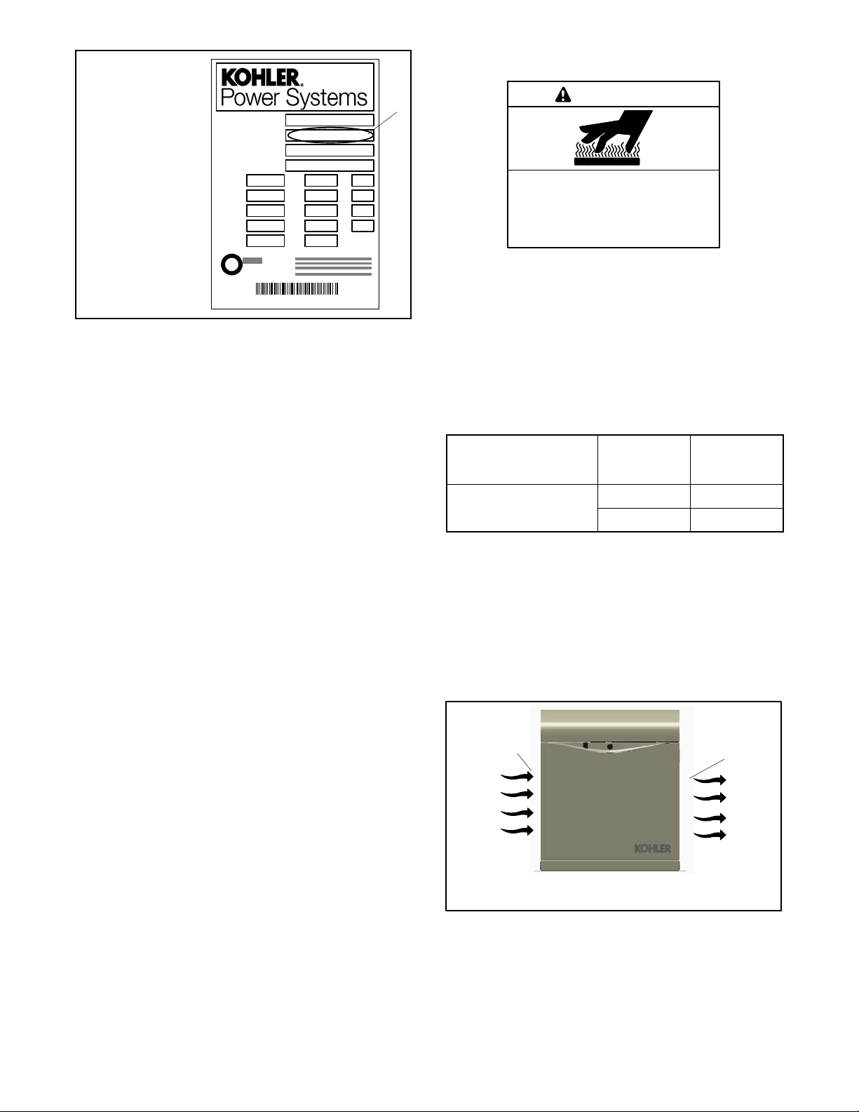
Product Identification Information
Generator Set Identification Numbers
Record the product identification numbers from the
generator set nameplate(s).
Model Designation
Specification Number
Serial Number
WARNING
Engine exhaust from this product contains
chemicals known to the State of California
to cause cancer, birth defects, or other
reproductive harm.
Engine Identification
Record the product identification information from the
engine nameplate.
Manufacturer
Model Designation
Serial Number
Accessory Number Accessory Description
Controller Identification
Record the controller description from the generator set
operation manual, spec sheet, or sales invoice.
Controller Description
Page 3

Table of Contents
Safety Precautions and Instructions 5.........................................................
Introduction 9...............................................................................
Startup and Registration 9.....................................................
Service Assistance 10.........................................................................
Section 1 Installation 11......................................................................
1.1 Introduction 11...........................................................
1.2 Lifting 12................................................................
1.3 Generator Set Inspection 12...............................................
1.4 Location and Mounting 12.................................................
1.4.1 Mounting Area 13................................................
1.4.2 Exhaust Requirements 13.........................................
1.5 Dimension Drawings 14...................................................
1.6 Access the Air Intake Area 14..............................................
1.7 Fuel Requirements 14.....................................................
1.7.1 Fuel Supply 14...................................................
1.7.2 Fuel Pipe Size 15.................................................
1.7.3 Connecting the Fuel Supply 16.....................................
1.8 Fuel Conversion 17.......................................................
1.9 Electrical Connections 19..................................................
1.9.1 Grounding 20....................................................
1.9.2 Electrical Lead Entry 20...........................................
1.9.3 Field-Connection Terminal Block 20.................................
1.9.4 AC Power Supply 21..............................................
1.10 ATS and Accessory Connections 22........................................
1.10.1 Transfer Switch Connection 22.....................................
1.10.2 Communication Cable Specifications 24.............................
1.10.3 System Connections with Accessory Modules 25.....................
1.11 Battery 28...............................................................
1.12 Prestart Installation Check 29..............................................
1.13 Set the Exerciser 30......................................................
1.13.1 RDC2 Controller 30...............................................
1.13.2 DC2 Controller 30................................................
1.13.3 Loaded Exercise 30...............................................
1.14 Operation Test 30........................................................
1.15 OnCue Plus Generator Management System 31..............................
Section 2 Accessories 33.....................................................................
2.1 Introduction 33...........................................................
2.2 Connect Optional Programmable Interface Module (PIM) 33...................
2.3 Load Management 34.....................................................
2.4 Carburetor Heater 35.....................................................
Section 3 Drawings and Diagrams 37..........................................................
Appendix A Abbreviations 43................................................................
TP-6984 5/17a Table of Contents 3
Page 4

Notes
TP-6984 5/17a4
Page 5
Safety Precautions and Instructions
IMPORTANT SAFETY INSTRUCTIONS.
Electromechanical equipment,
including generator sets, transfer
switches, switchgear, and accessories,
can cause bodily harm and pose
life-threatening danger when
improperly installed, operated, or
maintained. To prevent accidents be
aware of potential dangers and act
safely. Read and follow all safety
precautions and instructions. SAVE
THESE INSTRUCTIONS.
This manual has several types of safety
precautions and instructions: Danger,
Warning, Caution, and Notice.
DANGER
Danger indicates the presence of a
hazard that will cause severe
personal i njury, death,orsubstantial
property damage.
WARNING
Warning indicates the presence of a
hazard that can cause severe
personal injury, death, or substantial
property damage.
CAUTION
Caution indicates the presence of a
hazard that will or can cause minor
personal injury or property damage.
NOTICE
Notice communicates installation,
operation, or maintenance information
that is safety related but not hazard
related.
Safety decals affixed to the equipment
in prominent places alert the operator
or service technician to potential
hazards and explain how to act safely .
The decals are shown throughout this
publication to improve operator
recognition. Replace missing or
damaged decals.
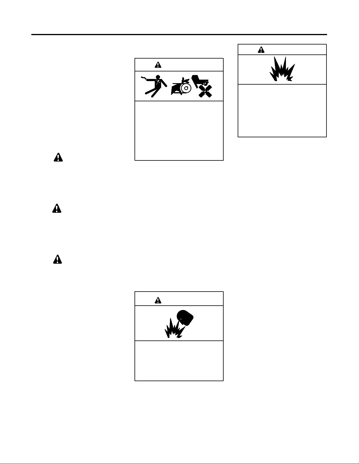
Accidental Starting
WARNING
Accidental starting.
Can cause severe injury or death.
Disconnect the battery cables before
working on the generator set.
Remove the negative (--) lead first
when disconnecting the battery.
Reconnect the negative (--) lead last
when reconnecting the battery.
Disabling the generator set.
Accidental starting can cause
severe injury or death. Before
working on the generator set or
equipment connected to the set,
disable the generator set as follows:
(1) Press the generator set off/reset
button to shut down the generator set.
(2) Disconnect the power to the battery
charger, if equipped. (3) Remove the
battery cables, negative (--) lead first.
Reconnect the negative (--) lead last
when reconnecting the battery. Follow
these precautions to prevent the
starting of the generator set by the
remote start/stop switch.
Battery
WARNING
Sulfuric acid in batteries.
Can cause severe injury or death.
Wear protective goggles and
clothing. Battery acid may cause
blindness and burn skin.
WARNING
Explosion.
Can cause severe injury or death.
Relays in the battery charger
cause arcs or sparks.
Locate the battery in a well-ventilated
area. Isolate the battery charger from
explosive fumes.
Battery electrolyte is a diluted
sulfuric acid. Battery acid can cause
severe injury or death. Battery acid
can cause blindness and burn skin.
Always wear splashproof safety
goggles, rubber gloves, and boots
when servicing the battery. Do not
open a sealed battery or mutilate the
battery case. If battery acid splashes in
the eyes or on the skin, immediately
flush the affected area for 15 minutes
with large quantities of clean water.
Seek immediate medical aid in the case
of eye contact. Never add acid to a
battery after placing the battery in
service, as this may result in hazardous
spattering of battery acid.
Battery acid cleanup. Battery acid
can cause severe injury or death.
Battery acid is electrically conductive
and corrosive. Add 500 g (1 lb.) of
bicarbonate of soda (baking soda) to a
container with 4 L (1 gal.) of water and
mix the neutralizing solution. Pour the
neutralizing solution on the spilled
battery acid and continue to add the
neutralizing solution to the spilled
battery acid until all evidence of a
chemical reaction (foaming) has
ceased. Flush the resulting liquid with
water and dry the area.
TP-6984 5/17a 5Safety Precautions and Instructions
Page 6
Battery gases. Explosion can cause
severe injury or death. Battery gases
can cause an explosion. Do not smoke
or permit flames or sparks to occur near
a battery at any time, particularly when
it is charging. Do not dispose of a
battery in a fire. To prevent burns and
sparks that could cause an explosion,
avoid touching the battery terminals
with tools or other metal objects.
Remove all jewelry before servicing the
equipment. Discharge static electricity
from your body before touching
batteries by first touching a grounded
metal surface away from the battery. To
avoid sparks, do not disturb the battery
charger connections while the battery
is charging. Always turn the battery
charger off before disconnecting the
battery connections. Ventilate the
compartments containing batteries to
prevent accumulation of explosive
gases.
Battery short circuits. Explosion
can cause severe injury or death.
Short circuits can cause bodily injury
and/or equipment damage.
Disconnect the battery before
generator set installation or
maintenance. Remove all jewelry
before servicing the equipment. Use
tools with insulated handles. Remove
the negative (--) lead first when
disconnecting the battery. Reconnect
the negative (--) lead last when
reconnecting the battery. Never
connect the negative (--) battery cable
to the positive (+) connection terminal
of the starter solenoid. Do not test the
battery condition by shorting the
terminals together.
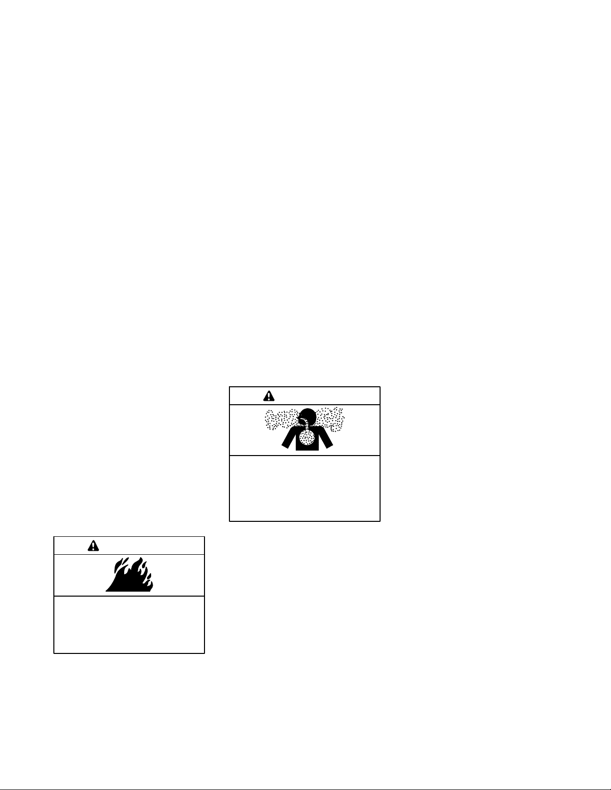
Engine Backfire/Flash
Fire
WARNING
Risk of fire.
Can cause severe injury or death.
Servicing the air cleaner. A sudden
backfire can cause severe injury or
death. Do not operate the generator
set with the air cleaner removed.
Servicing the fuel system. A flash
fire can cause severe injury or death.
Do not smoke or permit flames or
sparks near the carburetor, fuel line,
fuel filter, fuel pump, or other potential
sources of spilled fuels or fuel vapors.
Catch fuels in an approved container
when removing the fuel line or
carburetor.
Combustible materials. A fire can
cause severe injury or death.
Generator set engine fuels and fuel
vapors are flammable and explosive.
Handle these materials carefully to
minimize the risk of fire or explosion.
Equip the compartment or nearby area
with a fully charged fire extinguisher.
Select a fire extinguisher rated ABC or
BC for electrical fires or as
recommended by the local fire code or
an authorized agency. Train all
personnel on fire extinguisher
operation and fire prevention
procedures.
Exhaust System
WARNING
Carbon monoxide.
Can cause severe nausea,
fainting, or death.
The exhaust system must be
leakproof and routinely inspected.
Generator set operation. Carbon
monoxide can cause severe nausea,
fainting, or death. Carbon monoxide
is an odorless, colorless, tasteless,
nonirritating gas that can cause death if
inhaled for even a short time. Avoid
breathing exhaust fumes when working
on or near the generator set. Never
operate the generator set inside a
building. Never operate the generator
set where exhaust gas could seep
inside or be drawn into a potentially
occupied building through windows, air
intake vents, or other openings.
Carbon monoxide detectors.
Carbon monoxide can cause severe
nausea, fainting, or death. Install
carbon monoxide detectors on each
level of any building adjacent to the
generator set. Locate the detectors to
adequately warn the building’s
occupants of the presence of carbon
monoxide. Keep the detectors
operational at all times. Periodically
test and replace the carbon monoxide
detectors according to the
manufacturer’s instructions.
Carbon monoxide symptoms.
Carbon monoxide can cause severe
nausea, fainting, or death. Carbon
monoxide is a poisonous gas present in
exhaust gases. Carbon monoxide is an
odorless, colorless, tasteless,
nonirritating gas that can cause death if
inhaled for even a short time. Carbon
monoxide poisoning symptoms include
but are not limited to the following:
D Light-headedness, dizziness
D Physical fatigue, weakness in
joints and muscles
D Sleepiness, mental fatigue,
inability to concentrate
or speak clearly, blurred vision
D Stomachache, vomiting, nausea
If experiencing any of these symptoms
and carbon monoxide poisoning is
possible, seek fresh air immediately
and remain active. Do not sit, lie down,
or fall asleep. Alert others to the
possibility of carbon monoxide
poisoning. Seek medical attention if
the condition of affected persons does
not improve within minutes of breathing
fresh air.
Do not smoke or permit flames or
sparks near fuels or the fuel system.
TP-6984 5/17a6 Safety Precautions and Instructions
Page 7
Fuel System
Hazardous Noise
WARNING
WARNING
Explosive fuel vapors.
Can cause severe injury or death.
Use extreme care when handling,
storing, and using fuels.
The fuel system. Explosive fuel
vapors can cause severe injury or
death. Vaporized fuels are highly
explosive. Use extreme care when
handling and storing fuels. Store fuels
in a well-ventilated area away from
spark-producing equipment and out of
the reach of children. Never add fuel to
the tank while the engine is running
because spilled fuel may ignite on
contact with hot parts or from sparks.
Do not smoke or permit flames or
sparks to occur near sources of spilled
fuel or fuel vapors. Keep the fuel lines
and connections tight and in good
condition. Do not replace flexible fuel
lines with rigid lines. Use flexible
sections to avoid fuel line breakage
caused by vibration. Do not operate the
generator set in the presence of fuel
leaks, fuel accumulation, or sparks.
Repair fuel systems before resuming
generator set operation.
Gas fuel leaks. Explosive fuel
vapors can cause severe injury or
death. Fuel leakage can cause an
explosion. Check the LPG vapor or
natural gas fuel system for leakage by
using a soap and water solution with the
fuel system test pressurized to
6--8 ounces per square inch
(10--14 inches water column). Do not
use a soap solution containing either
ammonia or chlorine because both
prevent bubble formation. A successful
test depends on the ability of the
solution to bubble.
CAUTION
Hazardous noise.
Can cause hearing loss.
Never operate the generator set
without a muffler or with a faulty
exhaust system.
Engine noise. Hazardous noise can
cause hearing loss. Generator sets
not equipped with sound enclosures
can produce noise levels greater than
105 dBA. Prolonged exposure to noise
levels greater than 85 dBA can cause
permanent hearing loss. Wear hearing
protection when near an operating
generator set.
Hazardous Voltage/
Moving Parts
DANGER
Hazardous voltage.
Will cause severe injury or death.
This equipment must be installed and
serviced by qualified electrical
personnel.
WARNING
Hazardous voltage.
Can cause severe injury or death.
Moving parts.
Hazardous voltage.
Backfeed to the utility system can
cause property damage, severe
injury, or death.
If the generator set is used for
standby power, install an automatic
transfer switch to prevent inadvertent
interconnection of standby and
normal sources of supply.
CAUTION
Welding the generator set.
Can cause severe electrical
equipment damage.
Never weld components of the
generator set without first
disconnecting the battery, controller
wiring harness, and engine electronic
control module (ECM).
Grounding electrical equipment.
Hazardous voltage can cause
severe injury or death. Electrocution
is possible whenever electricity is
present. Ensure you comply with all
applicable codes and standards.
Electrically ground the generator set,
transfer switch, and related equipment
and electrical circuits. Turn off the main
circuit breakers of all power sources
before servicing the equipment. Never
contact electrical leads or appliances
when standing in water or on wet
ground because these conditions
increase the risk of electrocution.
Operate the generator set only when
all guards and electrical enclosures
areinplace.
TP-6984 5/17a 7Safety Precautions and Instructions
Page 8

Welding on the generator set. Can
cause severe electrical equipment
damage. Before welding on the
generator set perform the following
steps: (1) Remove the battery cables,
negative (--) lead first. (2) Disconnect
all engine electronic control module
(ECM) connectors. (3) Disconnect all
generator set controller and voltage
regulator circuit board connectors.
(4) Disconnect the engine batterycharging alternator connections.
(5) Attach the weld ground connection
close to the weld location.
Hot Parts
WARNING
Hot engine and exhaust system.
Can cause severe injury or death.
Do not work on the generator set until
it cools.
Notice
NOTICE
Canadian installations only.For
standby service connect the output of
the generator set to a suitably rated
transfer switch in accordance with
Canadian Electrical Code, Part 1.
Connecting the battery and the
battery charger. Hazardous voltage
can cause severe injury or death.
Reconnect the battery correctly,
positive to positive and negative to
negative, to avoid electrical shock and
damage to the battery charger and
battery(ies). Have a qualified
electrician install the battery(ies).
Short circuits. Hazardous
voltage/current can cause severe
injury or death. Short circuits can
cause bodily injury and/or equipment
damage. Do not contact electrical
connections with tools or jewelry while
making adjustments or repairs.
Remove all jewelry before servicing the
equipment.
Electrical backfeed to the utility.
Hazardous backfeed voltage can
cause severe injury or death. Install
a transfer switch in standby power
installations to prevent the connection
of standby and other sources of power.
Electrical backfeed into a utility
electrical system can cause severe
injury or death to utility personnel
working on power lines.
Servicing the exhaust system. Hot
parts can cause severe injury or
death. Do not touch hot engine parts.
The engine and exhaust system
components become extremely hot
during operation.
Servicing the engine heater. Hot
parts can cause minor personal
injury or property damage. Install the
heater before connecting it to power.
Operating the heater before installation
can cause burns and component
damage. Disconnect power to the
heater and allow it to cool before
servicing the heater or nearby parts.
Heavy Equipment
WARNING
Unbalanced weight.
Improper lifting can cause severe
injury or death and equipment
damage.
Do not use lifting eyes.
Lift the generator set using lifting bars
inserted through the lifting holes on
the skid.
TP-6984 5/17a8 Safety Precautions and Instructions
Page 9
Introduction
This manual provides installation instructions for Model
8/10/12RESV or 8/10/12RESVL generator sets. See
Figure 1. Refer to TP-6880, Operation Manual, for
generator set operation and maintenance instructions.
The generator set is approved for use in stationary
applications in locations served by a reliable utility
power source.
Have a Kohlerr authorized distributor/dealer install the
generator set outdoors according to the instructions in
this manual. The generator set installation must comply
with the National Electrical Code (NEC) and local code
requirements. Do not install this generator set indoors.
Information in this publication represents data available
at the time of print. Kohler Co. reserves the right to
change this publication and the products represented
without notice and without any obligation or liability
whatsoever.
Read this manual and carefully follow all procedures
and safety precautions to ensure proper equipment
operation and to avoid bodily injury. Read and follow the
Safety Precautions and Instructions section at the
beginning of this manual.
List of Related Literature
Figure 2 identifies related literature available for the
generator sets covered in this manual. Only trained and
qualified personnel should install or service the
generator set.
Literature Type Part Number
Spec Sheet, 8RESV G4--252
Spec Sheet, 8RESVL G4--253
Spec Sheet, 10/12RESV G4--254
Spec Sheet, 10/12RESVL G4--255
Operation Manual, Generator Set TP-6880
Operation/Installation Manual, Model
RXT Automatic Transfer Switch
Operation Manual, OnCuer Plus
Software
Operation Manual, SiteTecht
Software
Operation/Installation Manual,
Model RDT Transfer Switch
Installation Instructions,
Programmable Interface Module (PIM)
Installation Instructions, Load Shed Kit TT-1609
Installation Instructions, USB Utility TT-1636
Figure 2 Related Literature
TP-6807
TP-6928
TP-6701
TP-6345
TT-1584
Figure 1 Model RESV Generator Set
Startup and Registration
When the generator set is installed, complete the
startup and installation checklists supplied with the
startup notification form. Complete the startup
notification form and register the unit using the Kohler
online Warranty Processing System.
TP-6984 5/17a 9
Page 10

Service Assistance
For professional advice on generator set power
requirements and conscientious service, please contact
your nearest Kohler distributor or dealer.
D Consult the Yellow Pages under the heading
Generators—Electric.
D Visit the Kohler Power Systems website at
KOHLERPower.com.
D Look at the labels and decals on your Kohler product
or review the appropriate literature or documents
included with the product.
D Call toll free in the US and Canada 1-800-544-2444.
D Outside the US and Canada, call the nearest regional
office.
Headquarters Europe, Middle East, Africa
(EMEA)
Kohler Power Systems Netherlands B.V.
Kristallaan 1
4761 ZC Zevenbergen
The Netherlands
Phone: (31) 168 331630
Fax: (31) 168 331631
Asia Pacific
Power Systems Asia Pacific Regional Office
Singapore, Republic of Singapore
Phone: (65) 6264-6422
Fax: (65) 6264-6455
China
North China Regional Office, Beijing
Phone: (86) 10 6518 7950
(86) 10 6518 7951
(86) 10 6518 7952
Fax: (86) 10 6518 7955
East China Regional Office, Shanghai
Phone: (86) 21 6288 0500
Fax: (86) 21 6288 0550
India, Bangladesh, Sri Lanka
India Regional Office
Bangalore, India
Phone: (91) 80 3366208
(91) 80 3366231
Fax: (91) 80 3315972
Japan, Korea
North Asia Regional Office
Tokyo, Japan
Phone: (813) 3440-4515
Fax: (813) 3440-2727
TP-6984 5/17a10
Page 11
Section 1 Installation
1.1 Introduction
DANGER
Hazardous voltage.
Will cause severe injury or death.
This equipment must be installed and
serviced by qualified electrical personnel.
WARNING
Carbon monoxide.
Can cause severe nausea,
fainting, or death.
The exhaust system must be
leakproof and routinely inspected.
Note: DO NOT install these generator sets inside a
building.
Note: Install carbon monoxide (CO) detector(s) on
each level of any building adjacent to a generator
set. Locate the detectors to adequately warn the
building’s occupants of the presence of carbon
monoxide.
Obtain a building permit and contact your local utility
companies to mark the locations of underground pipes
and cables.
Read and follow the safety precautions in this manual
and observe the decals on the equipment. Refer to the
diagrams and drawings in this manual for dimensions
and electrical connections during the installation
procedure. Read the entire installation procedure and
obtain the accessories and tools needed before
beginning installation. Perform the steps in the order
shown.
To install optional accessories, follow the instructions
provided with each kit.
Generator set operation. Carbon monoxide can cause
severe nausea, fainting, or death. Carbon monoxide is an
odorless, colorless, tasteless, nonirritating gas that can cause
death if inhaled for even a short time. Avoid breathing exhaust
fumes when working on or near the generator set. Never
operate the generator set inside a building. Never operate the
generator set where exhaust gas could seep inside or be
drawn into a potentially occupied building through windows, air
intake vents, or other openings.
Carbon monoxide detectors. Carbon monoxide can
cause severe nausea, fainting, or death. Install carbon
monoxide detectors on each level of any building adjacent to
the generator set. Locate the detectors to adequately warn the
building’s occupants of the presence of carbon monoxide.
Keep the detectors operational at all times. Periodically test
and replace the carbon monoxide detectors according to the
manufacturer’s instructions.
Have the generator set installed b y an authorized Kohler
distributor/dealer or authorized representative. Install
the equipment in compliance with the National Electrical
Code (NEC) and local codes. For Canadian
installations, refer to the Canadian Electrical Code
(CEC).
The generator set must be installed outdoors. The
exhaust systems on enclosed units are designed for
outdoor installation only.
TP-6984 5/17a 11Section 1 Installation
Page 12
1.2 Lifting
WARNING
Unbalanced weight.
Improper lifting can cause severe
injury or death and equipment
damage.
Do not use lifting eyes.
Lift the generator set using lifting bars
inserted through the lifting holes on
the skid.
Approximate generator set weights are shown in
Figure 1-1. Use lifting bars inserted through the holes in
the skid to lift the unit. See the dimension drawings in
Section 3 for lifting hole locations.
Model Weight, kg (lb.)
8RESV/RESVL 170 (375)
10RESV/RESVL 194 (428)
12RESV/RESVL 196 (433)
Figure 1-1 Approximate Shipping Weights
1.3 Generator Set Inspection
Complete a thorough inspection of the generator set.
Check for the following:
1. Inspect the generator set for loose or damaged
parts or wires. Repair or tighten any loose parts
before installation.
2. Check the engine oil. Fill, if necessary, with the
recommended viscosity and grade of oil. Use
synthetic oil, API (American Petroleum Institute)
Service Class SG or higher. See TP-6880,
Operation Manual, for additional information.
1.4 Location and Mounting
Install the generator set outdoors near the incoming gas
service. The generator set location must allow easy
access for maintenance and service. The required
distance from a structure is dependent on state and local
codes. See the dimension drawing in Section 3 for the
minimum clearance from structures and
non-combustible materials.
Locate the generator set so that the hot exhaust does
not blow on plants or other combustible materials. No
plants, shrubs, or other combustible materials are
allowed within 1.2 m (4 ft.) of the exhaust end of the
generator set.
Do not install the generator set where exhaust gas could
accumulate and seep inside or be drawn into a
potentially occupied building. Furnace and other similar
intakes must be at least 3 m (10 ft.) from the exhaust
end of the generator set.
Notice
DO NOT locate the generator set near patios,
decks, play areas, or animal shelters. Keep items
such as lawn furniture, toys, sports equipment,
and all combustible materials away from the
generator set exhaust outlet.
Remind family members, children, and visitors to
use caution near the generator set. Generator sets
connected to automatic transfer switches start
automatically during exercise periods and power
outages. Some generator set components
become hot when the generator set is running and
remain hot for a time after the generator set shuts
down.
Note: The reduced minimum clearance from a structure
contained in ADV--8774 only applies to
generators that are compliant with clause (2) of
section 4.1.4 of NFPA 37. To verify that the
generator is compliant, check the Specification
Number located on the generator name plate.
See Figure 1-2. If the name plate displays one of
the following specification numbers, then the
generator is compliant with clause (2) of section
4.1.4 of NFPA 37 and the reduced clearance in
ADV--8774 (Figure 3-5) will apply.
D 8RESV: GM88347--GA7 or higher
D 8RESVL: GM88347--GA10 or higher
D 10RESV: GM88347--GA8 or higher
D 10RESVL: GM88347--GA11 or higher
D 12RESV: GM88347--GA9 or higher
D 12RESVL: GM88347--GA12 or higher
Note: If the generator set name plate does not
display one of the specification numbers set
forth above, refer to ADV-8539in installation
manual TP--6879 for the minimum
clearance from a structure.
TP-6984 5/17a12 Section 1 Installation
Page 13
1.4.2 Exhaust Requirements
8RESV-SA1
GM88347-GA7
XXXXXXXX
XXXXXXXX
29
Amps
Phase
RPM
3600
Battery
12V
NAT GAS
Fuel
kW
7.00
7.00
1
kVA
PF
1.0
Hz
60
1. Specification
Number
Genset Model
Spec Number
Serial Number
Material Number
Service Duty
STANDBY
Voltage
240
Alt Model
2F3
Insulation
07/31/2015
MFG Date
H
Figure 1-2 Name Plate
1.4.1 Mounting Area
The generator set is shipped on a wooden pallet.
Remove the wooden pallet before positioning the
generator set. Prepare a flat, level mounting area
covered with a weed barrier and gravel or a concrete
mounting pad. Set the generator set directly on the
gravel or concrete.
Note: When installing a concrete mounting pad, the
generator set must be secured to the mounting
pad to prevent shifting or movement caused by
engine vibration. For mounting pads
GM92228-KP1-QS and GM92228-KP2-QS, use
the screw inserts in the mounting pad to secure
the generator set. See TT--1619 for concrete
mounting pad installation instructions.
Do not install the generator set directly on grass, wood,
or other combustible materials. Clear all combustible
materials, including plants and shrubs, building
materials, and lawn furniture, from an area at least 1.2 m
(4 ft.) beyond the exhaust end of the generator set. See
the dimension drawing in Section 3.
1
WARNING
Hot engine and exhaust system.
Can cause severe injury or death.
Do not work on the generator set until
it cools.
Servicing the exhaust system. Hot parts can cause
severe injury or death. Do not touch hot engine parts. The
engine and exhaust system components become extremely
hot during operation.
Figure 1-3 gives the exhaust temperature at rated load.
Mount the generator set so that the hot exhaust does not
blow on plants or other combustible materials. Maintain
the clearances shown in the dimension drawing in
Section 3.
Temperature,
Exhaust Model
Exhaust gas exiting the
8RESV(L) 190 (374)
enclosure at rated kW,
_C(_F)
10/12RESV(L) 106 (224)
Figure 1-3 Exhaust Flow and Temperature
The generator set requires correct air flow for cooling
and combustion. The inlet and outlet openings in the
sound enclosure provide the cooling and combustion
air. Figure 1-4 shows the locations of the cooling air
intake and exhaust vents. Inspect the air inlet and outlet
openings inside and outside the housing to ensure that
the air flow is not blocked.
1
_C(_F)
2
1. Air intake
2. Exhaust outlet
FRONT VIEW
Figure 1-4 Cooling Air Intake and Exhaust
TP-6984 5/17a 13Section 1 Installation
tp6879
Page 14
1.5 Dimension Drawings
See the dimension drawings in Section 3 for the
generator set dimensions, fuel and electric inlet
locations, and recommended clearance.
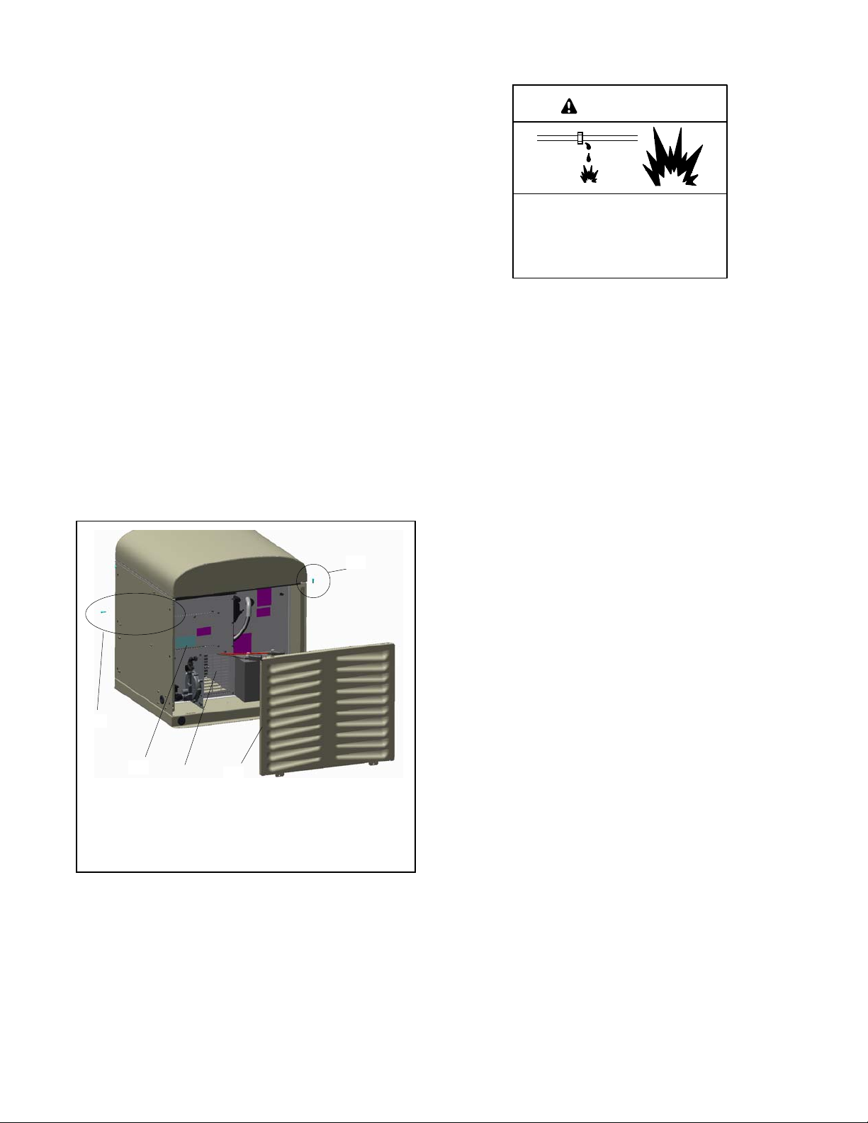
1.6 Access the Air Intake Area
1.7 Fuel Requirements
WARNING
The battery, fuel system, and electrical connections are
located in the air intake area. Raise the roof and remove
the enclosure panel to access the air intake area during
installation as described below.
Note: Ensure that the battery is positioned toward the
front of the generator so it does not block the
alternator air intake vent. See Figure 1-5.
1. Remove panel screws and remove the panel. Pull
the panel up and off. See Figure 1-5.
2. To make the electrical connections, you will also
need to remove the cover panel over the terminal
block.
3. Reinstall the panels after all electrical connections
are complete and the battery is installed and
connected.
1
Explosive fuel vapors.
Can cause severe injury or death.
Use extreme care when handling,
storing, and using fuels.
The fuel system. Explosive fuel vapors can cause severe
injury or death. Vaporized fuels are highly explosive. Use
extreme care when handling and storing fuels. Store fuels in a
well-ventilated area away from spark-producing equipment
and out of the reach of children. Never add fuel to the tank
while the engine is running because spilled fuel may ignite on
contact with hot parts or from sparks. Do not smoke or permit
flames or sparks to occur near sources of spilled fuel or fuel
vapors. Keep the fuel lines and connections tight and in good
condition. Do not replace flexible fuel lines with rigid lines. Use
flexible sections to avoid fuel line breakage caused by
vibration. Do not operate the generator set in the presence of
fuel leaks, fuel accumulation, or sparks. Repair fuel systems
before resuming generator set operation.
Gas fuel leaks. Explosive fuel vapors can cause severe
injury or death. Fuel leakage can cause an explosion. Check
the LPG vapor or natural gas fuel system for leakage by using
a soap and water solution with the fuel system test pressurized
to 6--8 ounces per square inch (10--14 inches water column).
Do not use a soap solution containing either ammonia or
chlorine because both prevent bubble formation. A successful
test depends on the ability of the solution to bubble.
1
3
4
1. Panel screws
2. Left side panel
3. Electrical cover panel
4. Alternator air intake vent
2
Figure 1-5 Remove Left Panel
GM80110
Explosive fuel vapors can cause severe injury or death.
Take additional precautions when using the following fuels:
Propane (LPG)—Adequate ventilation is mandatory.
Because propane is heavier than air, install propane gas
detectors low in a room. Inspect the detectors per the
manufacturer’s instructions.
Natural Gas—Adequate ventilation is mandatory. Because
natural gas rises, install natural gas detectors high in a room.
Inspect the detectors per the manufacturer’s instructions.
The generator set operates using natural gas or LPG
fuel. The generator set is EPA-certified for both natural
gas and LPG fuels.
The fuel system installation must comply with applicable
national, state, and local codes.
TP-6984 5/17a14 Section 1 Installation
Page 15
1.7.1 Fuel Supply
Verify that the output pressure from the primary gas
utility pressure regulator is as shown in Figure 1-6 and
Because of variable climates and geographical
considerations, contact the local fuel supplier for fuel
system planning and installation. Figure 1-6 lists the
recommended fuel ratings and other fuel supply
information for natural gas and LPG fuels.
that the utility gas meter flow rate is sufficient to supply
the generator set at rated load plus all other
gas-consuming appliances. For LPG tanks, verify that
the output pressure is as shown in Figure 1-6. See
Figure 1-9 for fuel consumption. Contact the fuel
supplier for flow rate information or a gas meter
Natural
3
Gas
0.87--2.7
(3.5-11)
LPG
1.7--2.7
(7-11)
Fuel type
Fuel supply inlet 1/2 NPT
Fuel supply pressure,
kPa (in. H
Fuel flow rate, maximum, Btu/hr.:
8RESV/RESVL 99,200 160,800
10RESV/RESVL 179,000 222,500
12RESV/RESVL 216,000 257,500
Nominal Fuel Rating, Btu/ft.
Natural gas 1000
LPG 2500
O)
2
upgrade, if necessary.
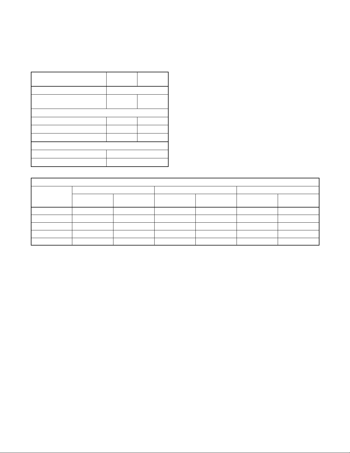
1.7.2 Fuel Pipe Size
Ensure that the fuel pipe size and length meet the
specifications in Figure 1-7. Measure the pipe length
from the primary gas pressure regulator to the pipe
connection on the generator set fuel inlet. Add 2.4 m
(8 ft.) to the measured length for each 90 degree elbow.
Compare the total pipe length with the chart in
Figure 1-7 to find the required pipe size.
Contact local LPG provider for LPG installation
information.
Figure 1-6 Fuel Supply
Minimum Gas Pipe Size Recommendation, in. NPT
8RESV/RESVL 10RESV/RESVL 12RESV/RESVL
Pipe Length,
m (ft.)
8 (25) 1/2 3/4 3/4 3/4 3/4 3/4
15 (50) 3/4 3/4 1 3/4 1 1
30 (100) 1 3/4 1 1 11/4 1
46 (150) 1 1 11/4 1 11/4 11/4
61 (200) 1 11/4 11/4 11/4 11/4 11/4
Natural Gas
(99,200 Btu/hr.)
LPG
(160,800 Btu/hr.)
Natural Gas
(179,000 Btu/hr.)
LPG
(222,500 Btu/hr.)
Natural Gas
(216,000 Btu/hr.)
(257,500 Btu/hr.)
Figure 1-7 Fuel Pipe Size Recommendations
LPG
TP-6984 5/17a 15Section 1 Installation
Page 16

1.7.3 Connecting the Fuel Supply
The dimension drawing in Section 3 shows the location
of the fuel inlet connection. Have the fuel supplier install
rigid gas piping and a manual fuel shut-off valve. The
fuel supply line should line up with the generator set fuel
inlet and end about 12 inches away to allow connection
with a section of flexible fuel line. Use flexible sections to
prevent fuel line breakage caused by vibration.
Note: Do not bend the flexible fuel line to make up for
misalignment of the fuel supply line and the
generator set fuel inlet.
Apply pipe sealant that is approved for fuel connections.
Hold the fuel solenoid valve with a wrench when
tightening the fuel connections.
Protect all fuel lines from machinery or equipment
contact, adverse weather conditions, and environmental
damage.
1
Note: Do not hold the fuel solenoid valve coil when
tightening the fuel connections. See Figure 1-8
for the recommended wrench locations.
Open the manual fuel valves and test all fuel
connections using soapy water. If a leak is found, close
the fuel valves, clean the fittings, and apply fresh
sealant. Check for fuel leaks again with the generator
set running.
8RESV/RESVL 10RESV/RESVL 12RESV/RESVL
Fuel Type % Load
100% 3.9 (136) 5.1 (179) 6.1 (216)
Natural Gas
LPG
LPG conversion factors:
8.58 ft.
0.535 m
36.39 ft.
3
=1lb.
3
=1kg
3
= 1 gal.
75% 2.7 (95) 4.1 (145) 4.5 (160)
50% 2.0 (69) 3.4 (120) 3.6 (128)
25% 1.5 (53) 2.7 (97) 2.8 (99)
100% 1.7 (59) 2.5 (89) 2.9 (103)
75% 1.3 (45) 2.0 (69) 2.2 (76)
50% 1.0 (36) 1.5 (52) 1.6 (57)
25% .75 (26) 1.1 (39) 1.2 (42)
Nominal fuel rating:
Natural gas: 37 MJ/m
LPG: 93 MJ/m
60 Hz 60 Hz 60 Hz
Figure 1-9 Fuel Consumption
1. Hold valve with wrench on flats of valve body
2. Alternate wrench location
Note: Do NOT hold the valve coil when tightening connections.
Figure 1-8 Holding Fuel Valve to Tighten Fuel
Connections
Fuel Consumption, m3/hr. (cfh)
3
(1000 Btu/ft.3)
3
(2500 Btu/ft.3)
2
TP-6984 5/17a16 Section 1 Installation
Page 17

1.8 Fuel Conversion
The multi-fuel system allows conversion from natural
gas (NG) to LPG (or vice-versa) in the field while
maintaining emissions-standard compliance. A trained
technician or an authorized distributor/dealer can
convert the fuel system.
WARNING
Use the following procedure to convert the fuel system.
The procedure includes removing the side panel,
removing the cap from the fuel selector valve, and
making the fuel selection.
See Figure 1-10 for fuel system components.
4
Accidental starting.
Can cause severe injury or death.
Disconnect the battery cables before
working on the generator set.
Remove the negative (--) lead first
when disconnecting the battery.
Reconnect the negative (--) lead last
when reconnecting the battery.
Disabling the generator set. Accidental starting can
cause severe injury or death. Before working on the
generator set or equipment connected to the set, disable the
generator set as follows: (1) Press the generator set off/reset
button to shut down the generator set. (2) Disconnect the
power to the battery charger, if equipped. (3) Remove the
battery cables, negative (--) lead first. Reconnect the negative
(--) lead last when reconnecting the battery. Follow these
precautions to prevent the starting of the generator set by the
remote start/stop switch.
WARNING
3
2
1. Gas shutoff valve
2. Gas regulator
3. Selector valve cap
4. Selector valve
1
Figure 1-10 Fuel System
1. Press the OFF button on the generator set
controller.
2. Disconnect the power to the battery charger.
3. Disconnect the generator set engine starting
battery, negative (--) lead first.
4. Turn off the fuel supply.
5. Remove panel screws and remove the left side
louvered panel. Figure 1-11.
tp6879
Explosive fuel vapors.
Can cause severe injury or death.
Use extreme care when handling,
storing, and using fuels.
1
Fuel Conversion Procedure
The fuel selector valve allows field-conversion between
natural gas (NG) and LPG. The valve is factory-set to
comply with applicable emission standards and to
provide the best possible hot and cold starting.
Note: Do not adjust the factory-set screw on the
selector valve. Adjusting the screw may violate
1
3
2
federal and state laws. See Figure 1-14.
1. Panel screws
2. Left side panel
3. Fuel system. See Figure 1-10 for details.
Figure 1-11 Remove Left Panel
TP-6984 5/17a 17Section 1 Installation
tp6879
Page 18

6. Remove the cap from the fuel selector valve. See
Figure 1-12. Insert a flat head screwdriver under
the lip of the cap and push it upwards. Keep the cap
close by as it is needed to switch fuels in the next
step.
1
1. Fuel selector cap
tp6879
Figure 1-12 Cap Removal
7. See Figure 1-13. Use the cap in the orientation
shown to turn the selector valve to NG or LP. See
Figure 1-14 for valve positions.
1
1. Fully left for LPG
2. Fully right for NG
3. Factory-set screw (Do not adjust!)
2
3
tp6879
Figure 1-14 Valve Positions
8. Replace the cap.
9. Connect and turn on the fuel supply (ensure that
the fuel supply matches the fuel setting).
10. Reconnect the generator set engine starting
battery leads, negative (--) lead last.
11. Reconnect power to the battery charger.
12. Reassemble the left side panel.
13. Start the generator set by pressing the RUN button
on the generator set controller.
1
1. Turn selector valve
Figure 1-13 Fuel Selection
tp6879
14. Check for leaks using a gas leak detector.
15. Run the generator set and check the operation.
16. Press the OFF button to to shut down the generator
set.
Rating
Converting the fuel will change the generator set rating.
See the generator set specification sheet for ratings with
natural gas and LPG. When converting to LPG from
factory settings, order a new nameplate with the
updated rating and fuel information from an authorized
distributor/dealer, if necessary. Provide the following
information from the original nameplate:
D Model Number D kVA
D Spec Number D Amps
D Serial Number D Volts
D Fuel (original and new) D Hz
D kW
TP-6984 5/17a18 Section 1 Installation
Page 19

1.9 Electrical Connections
DANGER
Hazardous voltage.
Will cause severe injury or death.
This equipment must be installed and
serviced by qualified electrical personnel.
Grounding electrical equipment. Hazardous voltage can
cause severe injury or death. Electrocution is possible
whenever electricity is present. Ensure you comply with all
applicable codes and standards. Electrically ground the
generator set, transfer switch, and related equipment and
electrical circuits. Turn off the main circuit breakers of all
power sources before servicing the equipment. Never contact
electrical leads or appliances when standing in water or on wet
ground because these conditions increase the risk of
electrocution.
Electrical backfeed to the utility. Hazardous backfeed
voltage can cause severe injury or death. Install a transfer
switch in standby power installations to prevent the connection
of standby and other sources of power. Electrical backfeed
into a utility electrical system can cause severe injury or death
to utility personnel working on power lines.
NOTICE
Canadian installations only. For standby service connect
the output of the generator set to a suitably rated transfer
switch in accordance with Canadian Electrical Code, Part 1.
Have an authorized distributor/dealer or a licensed
electrician make the following electrical connections.
The electrical installation must comply with the National
Electrical Coder (NEC) class 1 wire designation and all
applicable local codes. Canadian installations must
comply with the Canadian Electrical Code (CEC) and
applicable local codes.
AC circuit protection. All AC circuits must include
circuit breaker or fuse protection. The circuit breaker
must be rated for a maximum of 125% of the rated
generator set output current. The circuit breaker must
open all ungrounded connectors. The generator set is
equipped with a factory-installed circuit breaker.
For customer-supplied wiring, select the wire
temperature rating in Figure 1-15 based upon the
following criteria:
D Select row 1, 2, 3, or 4 if the circuit rating is
110 amperes or less or requires # 1 AWG (42.4 mm
2
or smaller conductors.
D Select row 3 or 4 if the circuit rating is greater than
110 amperes or requires #1 AWG (42.4 mm
2
)or
larger conductors.
)
Row Tem p . Rating Copper (Cu) Only Cu/Aluminum (Al) Combinations Al Only
1
60_C (140_F)
or
75_C (167_F)
2
60_C (140_F) Use No. * AWG, 60_Cwire Use 60_C wire, either No. * AWG Cu or No. *
3
75_C (167_F) Use No. *[ AWG, 75_Cwire Use 75_C wire, either No. *[ AWG Cu or No. *[
4
90_C (194_F) Use No. *[ AWG, 90_Cwire Use 90_C wire, either No. *[ AWG Cu or No. *[
* The wire size for 60_C (140_F) wire is not required to be included in the marking. If included, the wire size is based on ampacities for the
wire given in Table 310-16 of the National Electrical Coder, in ANSI/NFPA 70, and on 115% of the maximum current that the circuit carries
under rated conditions. The National Electrical Coder is a registered trademark of the National Fire Protection Association, Inc.
[ Use the larger of the following conductors: the same size conductor as that used for the temperature test or one selected using the
guidelines in the preceding footnote.
Use No. * AWG, 60_Cwireor
use No. * AWG, 75_Cwire
Use 60_C wire, either No. * AWG Cu, or No. *
AWG Al or use 75_C wire, either No. * AWG
Cu or No. * AWG Al
AWG Al
AWG Al
AWG Al
Use 60_Cwire,No.*AWGor
use 75_Cwire,No.*AWG
Use 60_Cwire,No.*AWG
Use 75_Cwire,No.*[ AWG
Use 90_Cwire,No.*[ AWG
Figure 1-15 Terminal Markings for Various Temperature Ratings and Conductors
The National Electrical Coder is a registered trademark of the National Fire Protection Association, Inc.
TP-6984 5/17a 19Section 1 Installation
Page 20

1.9.1 Grounding
1.9.3 Field-Connection Terminal Block
Ground the generator set. The grounding method must
comply with NEC and local codes. Connect the ground
to the generator set ground lug, terminal GND inside the
controller compartment.
The requirement for having a bonded (grounded)
neutral or ungrounded neutral is determined by the type
of installation. At installation, the neutral can be
grounded at the generator set or lifted from the ground
stud and isolated if the installation requires an
ungrounded neutral connection at the generator. The
generator set will operate properly with the neutral either
bonded to ground or isolated from ground at the
generator.
Note: When shipped, the generator neutral is not
bonded (grounded) to the generator ground.
Various regulations and site configurations including the
National Electrical Code (NEC), local codes, and the
type of transfer switch used in the application determine
the grounding of the neutral at the generator. NEC
Section 250 is one example that has a very good
explanation of the neutral grounding requirements for
generators.
1.9.2 Electrical Lead Entry
The generator set is equipped with a field-connection
terminal block located in the air inlet area inside the
junction box. Leads have been factory-installed from the
junction box to the terminal block for easy field wiring.
See Figure 1-17 for terminal block location. Remove the
cover panel for access to the field connections.
1
tp6879
1. Electrical cover panel
Drill or punch holes in the enclosure for the electrical
conduit in the locations shown in Figure 1-16.
2
1
1. 1/2 NPT female fuel inlet
2. Utility voltage electrical lead entry point
3. ATS signal electrical lead entry point
3
ADV--8539
Figure 1-17 Field-Connection Terminal Block
Location
See Figure 1-18 for terminal block details. Refer to the
terminal block decal for connections and cable sizes.
Also see the wiring diagram in Section 3.
Route AC leads through flexible conduit. Ensure that the
leads and conduit do not interfere with the operation of
the generator set or obstruct the service areas. Route
low-voltage communication leads through separate
conduit.
Figure 1-16 Electrical Lead Entry Locations
TP-6984 5/17a20 Section 1 Installation
Page 21

Procedure
1. Drill holes for the conduit fittings. See Figure 1-16
for the recommended electrical inlet locations.
Feed the cables through the openings.
2. Connect the leads from the transfer switch
emergency source lugs to the L1 and L2
connections on the generator set terminal block.
3. Connect the neutral (L0) and ground (GRD) leads
from the ATS and the main panel to the
corresponding connection points on the terminal
block. See Section 1.9.1, Grounding.
4. Connect utility power leads to the terminal block
connections labelled UTILITY. Connect to a circuit
that is supplied by the utility source and backed up
by the generator. See Section 1.9.4 for more
information about the utility power requirement.
5. For connection of optional transfer switches, the
programmable interface module (PIM), and/or a
load shed kit, see Section 1.10.
6. To connect the OnCuer Plus Generator
Management System to your generator, run
network cable from the generator set to the
customer’s router or modem.
7. When connections to the terminal block are
complete, replace the cover plate.
3
2
1
1. Ground connection for communication cable shield.
2. Low voltage communication and engine start
connections
3. AC power connections
4. Ethernet cable for OnCue Plus connection
5. AC load connections
5
4
GM88354
Figure 1-18 Electrical Connections
a. Route the network cable with other low-voltage
signal wiring (for example, the RBUS
communication leads or engine start leads to
the transfer switch), in separate conduit from
the AC load leads. If the network cable is longer
than 100 meters (328 ft.), use a repeater or
switch.
b. Test the internet connection for the generator
by connecting a laptop to the network cable.
(1) Turn OFF any wireless connections to the
laptop.
(2) Connect the network cable to the laptop.
Connect the other end of the network cable
to the customer’s router or modem.
(3) Verify the Internet connection by opening
your web browser and going to
www.kohlerpower.com or any known
website.
(4) Disconnect the network cable from the
laptop.
c. Use an RJ45 inline coupler to connect the
Ethernet cable to the cable in the customer
connection box. See Figure 1-18. The inline
coupler is included with the OnCue Plus kit.
1.9.4 AC Power Supply
The installer must connect AC power for the battery
charger (which is integral to the RDC2 controller) and
the optional accessories shown in Figure 1-19. The
power source must comply with state and local codes.
The power to the battery charger and accessories must
be backed up by the generator so that power is available
at all times.
Be sure to disconnect power at the distribution panel
before making the connections. Connect power leads to
the utility power connection points on the terminal block.
See Section 1.9.3 and the wiring diagrams in Section 3
for connection details.
Power Requirement, Max.
Equipment
Battery charger (standard)
Carburetor heater *
* Optional accessory
Figure 1-19 Power Requirements
Watts Amps Volts
50 0.4
37 0.3
100--250 VAC
50/60 Hz
120 VAC
50/60 Hz
TP-6984 5/17a 21Section 1 Installation
Page 22

1.10 ATS and Accessory
Connections
WARNING
1.10.1 Transfer Switch Connection
Connect the ATS or remote start/stop switch. Connect
the load leads from the generator set to the Emergency
source lugs on the ATS. Route low-voltage
communication leads through separate conduit from the
AC power and load leads. All connections must comply
with applicable state and local codes.
Hazardous voltage.
Backfeed to the utility system can
cause property damage, severe
injury, or death.
If the generator set is used for
standby power, install an automatic
transfer switch to prevent inadvertent
interconnection of standby and
normal sources of supply.
The following sections cover electrical connections of
the automatic transfer switches and RBUS accessories,
including the programmable interface module ( PIM), or
the load shed kit.
Note: Load shed kits are not available when combined
with the transfer switch supplied with models
8RESVL, 10RESVL, 12RESVL.
Generator Set
GND
1
Note: Do not use the Kohlerr Model RRT transfer
switch with the RESV or RESVL generator set.
Communication connections for a Kohlerr
Model RXT transfer switch
One Model RXT transfer switch can be connected to the
generator set. See Figure 1-20. Use shielded,
twisted-pair communication cable to connect P10-1
through P10-4 on the transfer switch interface module to
the generator set terminal block connections A, B, PWR,
and COM.
The Model RXT transfer switch with the combined
interface/load management board requires one set of
RBUS connections to the generator set. However, the
combined board acts as two RBUS modules: one RXT
transfer switch and one load management device.
Note: Connections 3 and 4 on the generator set are not
used with the Model RXT transfer switch.
2
3
4
COM
PWR
B
A
Interface Board on the
Model RXT Transfer Switch
4
3
A
B
PWR
COM
4
RXT
12 VDC
RBUS
COM
PWR
B
A
TB3
Note: Generator set terminal block (TB3) connections 3 and 4 are NOT USED with the Model RXT ATS.
1. Generator set terminal block TB3. See Figure 3-5 for location. Check the decal on the generator set for terminal block connections.
2. Connect one end of each cable shield to GROUND at the generator set.
3. Communication cable Belden #9402 or equivalent 20 AWG shielded, twisted-pair cable. Section 1.10.2
4. Leave one end of each cable shield disconnected.
Figure 1-20 Model RXT Transfer Switch Communication Connection to Generator Set Terminal Block
TP-6984 5/17a22 Section 1 Installation
Page 23

Engine start connection for other transfer
switches or a remote start/stop switch
Connect the engine start leads from the transfer switch
terminal block. See Figure 1-21. Route the engine start
leads through separate conduit from the AC power and
load leads.
or remote start switch to terminals 3 and 4 on the
1
Generator Set ATS
2
(with engine
start contacts)
3
4
COM
PWR
B
A
TB3
1. Generator Set Terminal Block. See the dimension drawings in Section 3 for location. Check the decal on the generator set for terminal
block connections.
2. Engine start leads 3 and 4. See the ATS manual for cable size specifications.
tp6803
Figure 1-21 Engine Start Connections with Transfer Switch Models other than Model RXT
TP-6984 5/17a 23Section 1 Installation
Page 24

1.10.2 Communication Cable
Specifications
PWR and COM Connections
For the PWR and COM connections from the generator
set to the RXT, PIM and/or load shed kit, use the second
RBUS Connections A and B
For the RBUS communication connections A and B to
the Model RXT transfer switch, optional PIM and/or
optional load shed kit, use 20 AWG shielded,
twisted-pair communication cable. Belden #9402
(two-pair) or Belden #8762 (single-pair) or equivalent
cable is recommended.
For outdoor installations, including those with buried
cables and/or conduit, use outdoor-rated Belden
#1075A or equivalent 20 AWG shielded, twisted-pair
communication cable.
pair in the two-pair communication cable for short runs,
or use 12--14 AWG cable for longer runs as shown in
Figure 1-22.
The maximum cable length depends on the number of
optional modules connected. A module can be a Model
RXT transfer switch, a load management device, or a
programmable interface module (PIM). See Figure 1-22
for the maximum cable lengths for 1, 2, or 3 modules per
cable run. Note the shield connections shown in
Figure 1-24.
Note: A model RXT transfer switch with combined
interface/load management board acts as two
RBUS modules: one RXT transfer switch and one
load management device.
Note: Power relay modules, if used, are not RBUS
modules and do not have RBUS communication
connections.
Maximum length per run, meters (ft.)
Indoor or
Outdoor In-
Cable Size for PWR and COM Connections
20 AWG Belden #9402 or equivalent, two-pair Indoor 61 (200) 31 (100) 21 (67)
20 AWG Belden #1075A or equivalent, two-pair Outdoor 61 (200) 31 (100) 21 (67)
14 AWG * — 152 (500) 152 (500) 122 (400)
12 AWG * — 152 (500) 152 (500) 152 (500)
* Use 12 or 14 AWG cable for PWR and COM connections only. For RBUS connections A and B, use shielded, twisted pair communication
cable specified in Section 1.10.2.
stallation
Number of Modules (ATS, PIM, or Load Shed Kit)
per Run
1 Module 2 Modules 3 Modules
Figure 1-22 Total Cable Lengths for PWR and COM Connections
TP-6984 5/17a24 Section 1 Installation
Page 25

1.10.3 System Connections with
Accessory Modules
programmable interface module (PIM) and one load
shed kit.
See Figure 1-24 through Figure 1-26 for connection
options with accessory modules. Accessory modules
can include one Model RXT transfer switch, one
1
Generator Set
12 VDC
RBUS
GND
COM
PWR
TB3
3
4
COM
PWR
B
A
B
A
See Figure 1-22 for the maximum total cable length with
1, 2, or 3 accessory modules per cable run.
2
3
Load Shed Kit
A
B
PWR
COM
4
A
B
PWR
COM
RXT*
A
B
PWR
COM
PIM
Note: See Section 1.10.2, Cable Specifications for
maximum cable lengths.
* RXT transfer switch with standard or combined interface/load
management board. Do not use a load shed kit with a
5
A
B
PWR
COM
combined interface board.
5
1. Customer connection terminal block. See Figure 1-18 for location. Check the decal on the generator set for terminal block connections.
2. Connect one end of each cable shield to GROUND at the generator set.
3. See Figure 1-22 for cable specifications, including maximum total cable length per run (1 run shown).
4. Connect shields together as shown.
5. Leave the end of each cable shield disconnected at the last device.
A
B
PWR
COM
Figure 1-23 Accessory Module Communication Connection Details
TP-6984 5/17a 25Section 1 Installation
Page 26

1
GND
2
Generator Set
12 VDC
RBUS
3
4
COM
PWR
B
A
TB3
COM
PWR
B
A
3
Load Shed Kit
A
B
PWR
COM
6
4
COMA PWRB
RXT*
A
B
PWR
COM
A
B
PWR
COM
PIM
Note: See Section 1.10.2, Cable Specifications for
maximum cable lengths.
* RXT transfer switch with standard or combined interface/load
management board. Do not use a load shed kit with a
combined interface board.
5
A
B
PWR
COM
1. Generator set terminal block. See Figure 3-5 for location. Check the decal on the generator set for terminal block connections.
2. Connect one end of each cable shield to GROUND at the generator set.
3. Communication cable Belden #8762 or equivalent 20 AWG shielded, twisted-pair cable (one pair).
4. Connect shields together as shown.
5. Leave one end of each cable shield disconnected at the last device.
6. 12 AWG or 14 AWG leads for PWR and COM.
Figure 1-24 Accessory Module Communication Connection Details
TP-6984 5/17a26 Section 1 Installation
Page 27

1
3
Generator Set
3
4
12 VDC
RBUS
1. Generator Set Terminal Block TB3. See Figure 3-5 for location. Check the decal on the generator set for terminal block connections.
2. Splice
3. Connect all of the shield leads on this end to GROUND at the generator set.
COM
PWR
B
A
TB3
2
COM
PWR
B
A
3
COM
PWR
B
A
9402 CABLE
9402 CABLE
Figure 1-25 Multiple Connections to the Generator Set
tp6803
Generator Set
Terminal
Block
Notes:
Load
Shed
Kit
RXT ATS
D See Figure 3-6 for terminal block location on generator
set. Check the decal on the generator set for terminal block
connections.
D See Section 1.10.2, Cable Specifications.
D See Figure 1-24 for communication connection detail (A
and B, PWR and COM). Connect the cable shield to
ground at the generator set.
PIM
D Use splices or wire nuts to collect multiple leads for
connection to the generator set terminal block. See
Figure 1-25.
Figure 1-26 Accessory Module Connections (two cable runs with one and two modules shown)
tp6809
TP-6984 5/17a 27Section 1 Installation
Page 28

1.11 Battery
WARNING
Sulfuric acid in batteries.
Can cause severe injury or death.
Wear protective goggles and
clothing. Battery acid may cause
blindness and burn skin.
WARNING
Explosion.
Can cause severe injury or death.
Relays in the battery charger
cause arcs or sparks.
Locate the battery in a well-ventilated
area. Isolate the battery charger from
explosive fumes.
Battery electrolyte is a diluted sulfuric acid. Battery acid
can cause severe injury or death. Battery acid can cause
blindness and burn skin. Always wear splashproof safety
goggles, rubber gloves, and boots when servicing the battery.
Do not open a sealed battery or mutilate the battery case. If
battery acid splashes in the eyes or on the skin, immediately
flush the affected area for 15 minutes with large quantities of
clean water. Seek immediate medical aid in the case of eye
contact. Never add acid to a battery after placing the battery in
service, as this may result in hazardous spattering of battery
acid.
Battery acid cleanup. Battery acid can cause severe
injury or death. Battery acid is electrically conductive and
corrosive. Add 500 g (1 lb.) of bicarbonate of soda (baking
soda) to a container with4L(1gal.)ofwaterandmixthe
neutralizing solution. Pour the neutralizing solution on the
spilled battery acid and continue to add the neutralizing
solution to the spilled battery acid until all evidence of a
chemical reaction (foaming) has ceased. Flush the resulting
liquid with water and dry the area.
Battery gases. Explosion can cause severe injury or
death. Battery gases can cause an explosion. Do not smoke
or permit flames or sparks to occur near a battery at any time,
particularly when it is charging. Do not dispose of a battery in a
fire. To prevent burns and sparks that could cause an
explosion, avoid touching the battery terminals with tools or
other metal objects. Remove all jewelry before servicing the
equipment. Discharge static electricity from your body before
touching batteries by first touching a grounded metal surface
away from the battery. To avoid sparks, do not disturb the
battery charger connections while the battery is charging.
Always turn the battery charger off before disconnecting the
battery connections. Ventilate the compartments containing
batteries to prevent accumulation of explosive gases.
Battery short circuits. Explosion can cause severe injury
or death. Short circuits can cause bodily injury and/or
equipment damage. Disconnect the battery before generator
set installation or maintenance. Remove all jewelry before
servicing the equipment. Use tools with insulated handles.
Remove the negative (--) lead first when disconnecting the
battery. Reconnect the negative (--) lead last when
reconnecting the battery. Never connect the negative (--)
battery cable to the positive (+) connection terminal of the
starter solenoid. Do not test the battery condition by shorting
the terminals together.
Connecting the battery and the battery charger.
Hazardous voltage can cause severe injury or death.
Reconnect the battery correctly, positive to positive and
negative to negative, to avoid electrical shock and damage to
the battery charger and battery(ies). Have a qualified
electrician install the battery(ies).
Starting batteries are usually the lead-acid type. Use a
12-volt group 51 battery with a minimum rating of 500
cold cranking amps at 0_F. The generator set uses a
negative ground with a 12-volt engine electrical system.
See Figure 1-27 for battery connections. Make sure that
the battery is correctly connected and the terminals are
tight.
Note: The generator set will not start and circuit board
damage may occur if the battery is connected in
reverse.
See the dimension drawing in Section 3 for the engine
starting battery location on the air intake side of the
generator set. Standard battery cables provide easy
connection to the battery.
TP-6984 5/17a28 Section 1 Installation
Page 29

1
2
1.12 Prestart Installation Check
Review the entire installation section. Inspect all wiring
and connections to verify that the generator set is ready
for operation. Check all items in the following Prestart
Checklist.
1. To positive (+) terminal on starter solenoid.
2. To ground (--) terminal on or near starter motor.
EZ-273000-J
Figure 1-27 Typical Battery Connection
Use the following procedure to install and connect the
battery.
Battery Installation Procedure
1. Ensure that the starting battery is fully charged
before placing the battery in service.
2. Clean the battery posts and/or adapters if
necessary.
3. Install the battery post adapters, if needed.
4. Place the battery in the housing.
Note: Ensure that the battery is positioned toward
the front of the generator so it does not block
the alternator air intake vent. See
Figure 1-5.
Prestart Checklist
Air Cleaner. Check that a clean air cleaner element is
installed to prevent unfiltered air from entering the
engine. See the generator set operation manual for
instructions.
Air Inlets. Check for clean and unobstructed air inlets.
Battery. Check for tight battery connections. Consult
the battery manufacturer’s instructions regarding
battery care and maintenance.
Enclosure. Check that all enclosure panels and internal
baffling are in place.
Exhaust System. Check for exhaust leaks and
blockages. Check the muffler condition.
D Inspect the exhaust system components for cracks,
leaks, and corrosion. Check for tight exhaust system
connections.
D Check for corroded or broken metal parts and replace
them as needed.
5. Connect the positive (+) lead to the engine starting
battery.
6. Connect the negative (-- ) lead to the engine starting
battery.
Refer to the generator set operation manual and the
battery manufacturer’s instructions for battery
maintenance instructions.
When power is applied to the RDC2/DC2 controller (that
is, when the battery is connected), you will be prompted
to set the date and time, and then to set the exerciser.
See Section 1.13 and the generator set operation
manual for instructions.
If the battery is disconnected for service or replacement,
the exercise settings on the RDC2/DC2 controller are
lost. Set the exerciser after installing and connecting the
battery. See Section 1.13, Set Exerciser.
D Check that the exhaust outlet is unobstructed.
Oil Level. Maintain the oil level at or near, not over, the
full mark on the dipstick.
Operating Area. Check for obstructions that could
block the flow of cooling air. Keep the air intake area
clean. Do not leave rags, tools, or debris on or near the
generator set.
TP-6984 5/17a 29Section 1 Installation
Page 30

1.13 Set the Exerciser
1.13.2 DC2 Controller
Set the exerciser to automatically run the generator set
on the desired day and time every week or every two
weeks. See the generator set Operation Manual for
detailed descriptions of the unloaded and loaded
exercise operation.
Note: Your generator will use either the RDC2 (RESV
models) or the DC2 (RESVL models) controller.
Determine which controller your generator set
uses and follow the directions to set that specific
controller. See Figure 1-28.
RDC2 (RESV) DC2 (RESVL)
Figure 1-28 Controller Identification
1.13.1 RDC2 Controller
To set the exerciser on the DC2 controller, first press
AUTO to place the controller into automatic (standby)
mode. Then press and hold the Exercise button. The
generator set will start and run a 20-minute unloaded
cycle exercise. The generator set will run automatically
for 20 minutes at the same time every 7 days. See the
generator set Operation Manual for more information.
1.13.3 Loaded Exercise
In order to set a loaded exercise using the RDC2 or DC2
controller, a Kohlerr Model RXT transfer switch must be
connected. See the generator set operation manual for
instructions to set a loaded exercise.
To set a loaded exercise on a generator set connected to
a transfer switch other than a Model RXT, use the
transfer switch controller to set the exercise. Refer to the
transfer switch operation manual for instructions.
1.14 Operation Test
WARNING
When power is applied to the RDC2 controller (when the
battery or the utility power for the battery charger is
connected), you will be prompted to set the date and
time, and then to set the exerciser.
The first setting will flash. Press the Up and Down arrow
buttons to change the setting. Press Select to save the
setting and move on to the next. Repeat until the date,
time, and exercise are set and the controller display
shows the main menu. See the generator set Operation
Manual for more detailed instructions to set the date and
time and set the exerciser.
Press AUTO to place the generator set controller into
automatic mode.
Date:
05Dec2011
Time:
08:31am
Next Exercise:
08:31a 12Dec2011
Setting will flash.
Press the up and down arrow
buttons to change the setting.
Press Select to save the setting.
tp6803
Figure 1-29 Set Time, Date, and Exercise (RDC2)
Hazardous voltage.
Can cause severe injury or death.
Operate the generator set only when
all guards and electrical enclosures
areinplace.
Moving parts.
1. Verify that all guards and enclosure panels are in
place.
2. Check the items in the Prestart Checklist in
Section 1.12.
3. Press the RUN button on the generator set
controller to start the generator set. Verify that the
engine starts and runs.
4. Use a digital voltmeter (DVM) to check the output
voltage (line to line and line to neutral) from the
generator set. If voltage calibration is required,
refer voltage calibration instructions in the service
manual.
5. Press OFF to stop the engine. Then press AUTO
on the RDC2 controller.
6. Verify that the enclosure door is closed and that the
panels are installed. Lock the enclosure to prevent
unauthorized access.
TP-6984 5/17a30 Section 1 Installation
Page 31

1.15 OnCue Plus Generator
Management System
The OnCuer Plus Generator Management System is
included with the 8RESV(L), 10RESV(L), and
12RESV(L) and allows monitoring and control of your
generator set from a personal computer, smart phone,
or tablet. OnCue Plus can also be configured to send
email or text message notifications in the event of a
generator set fault. See G18-247, Quick Start Guide and
TP--6928, OnCue Plus Operation Manual, for
instructions.
To use OnCue Plus, you must have the following
minimum requirements for connecting your generator to
the Internet:
D “Always-on” Internet service for generator set
connection (for example, cable, DSL, or phone line
modem connected 24 hours)
D Unused Ethernet port on a switch, router,or modem
D An uninterruptible power supply (UPS) for the modem
and router is recommended.
D 5E customer-supplied network cable for connection
of the generator set to the customer’s Ethernet router
(see installation instructions in Section 1.9.3)
D USB cable, male USB A to male mini-B, for updating
the controller firmware.
For instructions on connecting the network cables to the
generator set, see instructions in Section 1.9.3.
TP-6984 5/17a 31Section 1 Installation
Page 32

Notes
TP-6984 5/17a32 Section 1 Installation
Page 33

2.1 Introduction
This section describes some of the accessories that are
available for the generator sets. Have accessories
installed by an authorized distributor/ dealer or a
licensed electrician. This document does not contain
installation instructions for accessories. Follow the
installation instructions provided with each kit.
Section 2 Accessories
1
1
Use separate conduit for AC and DC leads to reduce the
possibility of electrical interference. Verify that the leads
and conduit do not interfere with the operation of the
generator set or obstruct the service areas. Verify that
the electrical installation complies with the National
Electrical Code (NEC) and all applicable local codes.
See the wiring diagrams in Section 3 for more
information regarding generator set electrical
connections.
2.2 Connect Optional
Programmable Interface
Module (PIM)
The optional programmable interface module (PIM)
provides two programmable inputs and six dry contact
outputs, four of which are programmable. See TT-1584
for PIM installation and connection instructions. Also
see Section 1.10 of this manual for connection to the
generator set.
The default settings for the inputs and outputs are
shown in Figure 2-2. To change the input and output
settings, use a personal computer running Kohler
SiteTechr software. See TP-6701, SiteTech Software
Operation Manual, for instructions.
Kohler OnCuer Plus can be used to actively control PIM
outputs. See the OnCue Plus Operation Manual for
instructions.
2
3
1
ADV-8199
1. Output connections (3 terminal blocks, 6 outputs)
2. Input connections (2 inputs)
3. RBUS communication connection to generator set terminal
block TB2
Figure 2-1 Optional PIM
PIM Connection Factory Default Setting
Input 1 None
Input 2 None
Output 1 (Relay 1) Run
Output 2 (Relay 2) Common Fault
Output 3 (Relay 3) Low Battery Voltage (Program-
mable)
Output 4 (Relay 4) Not in Auto (Programmable)
Output 5 (Relay 5) Cooldown (Programmable)
Output 6 (Relay 6) Normal Source Failure (Program-
mable)
Figure 2-2 PIM Inputs and Outputs
TP-6984 5/17a 33Section 2 Accessories
Page 34

2.3 Load Management
On models 8RESV, 10RESV, and 12RESV,two optional
load management devices are available for use when
combined with a model RXT and RDT transfer switch:
D The optional Load Shed Kit mounts inside a model
RDT or RXT transfer switch. Figure 2-3 shows the
load shed assembly.
D The combined interface/load management board is
available for the Model RXT transfer switch.
system installation complies with all applicable state
and local codes.
For detailed installation and connection instructions,
see TT-1609, provided with the load shed kit, or
TP-6807, Operation/Installation Manual for the Model
RXT transfer switch with combined interface/load
management board.
1
Note: Load shed kits are not available with the transfer
switch supplied with models 8RESVL, 10RESVL,
12RESVL.
The devices provide an automatic load management
system to comply with Section 702.5 of NEC 2008.
Note: The load management devices are only
compatible with single-phase generator sets.
With a load management system, less critical
appliances can be powered by the generator set when
the more important appliances are not running, allowing
the use of a smaller generator set than would be needed
to run all of the building’s electrical equipment at the
same time.
The load management device automatically manages
up to six residential loads.
D Two relays are included to control two independent
heating, ventilation, and air conditioning (HVAC)
loads.
D Up to four power relays (or load management
modules) can be connected through normally open
relay contacts on the circuit board. Load
management modules are available separately.
Load management modules include one power relay
mounted inside a NEMA type 3 R enclosure. Connectup
to four (4) load management modules to the load
management devices listed above.
2
3
1. Terminal block TB10
2. Load control circuit board
3. Mounting bracket
Note: Kit includes current transformer (CT), not shown.
GM88281
Figure 2-3 Load Shed Assembly GM88281-1
(mounts inside the transfer switch
enclosure)
2.3.1 Power Relay Module
The power relay module kit contains one 50 amp relay
with connecting lugs in a NEMA type 3R enclosure.
Connect up to four (4) power relay modules to the load
management devices listed above.
The power relay modules can be mounted indoors or
outdoors. Two(2) 120 VACloads (shed simultaneously)
or a single 240 VAC load can be wired to each relay.
For detailed installation and connection instructions,
see TT-1646, provided with the power relay module kit.
The load management device receives commands from
the RDC2 or DC2 generator controller and energizes or
de-energizes the appropriate load relays to add or shed
non-critical loads according to their priority.
Note: Connect only non-essential loads to the load
shed kit.
An adequate electrical supply is r equired for operation
of the customer-supplied power relays connected to the
load shed kit. Check the electrical requirements of the
customer-provided equipment prior to installation to
determine the wire size and circuit protection required.
The installer is responsible for ensuring that the power
Figure 2-4 Power Relay Module
TP-6984 5/17a34 Section 2 Accessories
Page 35

2.4 Carburetor Heater
WARNING
Hot engine and exhaust system.
Can cause severe injury or death.
Do not work on the generator set until
it cools.
Servicing the engine heater. Hot parts can cause minor
personal injury or property damage. Install the heater
before connecting it to power. Operating the heater before
installation can cause burns and component damage.
Disconnect power to the heater and allow it to cool before
servicing the heater or nearby parts.
An optional carburetor heater is recommended for
improved cold starting in locations where the ambient
temperature drops below 0_C(32_F). The carburetor
heater prevents condensation and carburetor icing. The
heater turns on when the temperature at the thermostat
falls below approximately 4_C(40_F) and turns off when
the temperature rises above approximately 16_C
(60_F). The carburetor heater is shown in Figure 2-6.
To install the carburetor heater, follow the instructions
provided with the kit. Figure 2-7 shows the installed
carburetor heater kit.
Verify that AC power is connected to the generator set
as described in Section 1.9. The circuit must be backed
up by the generator set to provide power at all times.
1
1. Power plug
2. Thermostat
3. Heater
2
Figure 2-6 Carburetor Heater
1
8RESV(L)
1
3
GM57968
2
The heater thermostat is installed in the cord. Figure 2-6
shows the location of the thermostat on the power cord.
The heater power cord and thermostat are located in the
generator set housing air intake area/ battery
compartment.
The heater requires a continuous source of power. Plug
the carburetor heater into the 120 VAC receptacle
provided.
Kit Number 120 Volt Kits
Voltage 120 VAC
Thermostat ON
Thermostat OFF
Figure 2-5 Carburetor Heater Specifications
50/60 Hz
4 ± 4_C(40± 7_F)
16 ± 3_C(60± 5_F)
10/12RESV(L)
1. Carburetor heater
2. Carburetor heater power cord
Figure 2-7 Carburetor Heater Location
TP-6984 5/17a 35Section 2 Accessories
2
GM57969
Page 36

Notes
TP-6984 5/17a36 Section 2 Accessories
Page 37

Figure 3-2 lists the wiring diagram numbers and page
numbers.
Section 3 Drawings and D iagrams
Note: The reduced minimum clearance from a structure
contained in ADV--8774 only applies to
generators that are compliant with clause (2) of
section 4.1.4 of NFPA 37. To verify that the
generator is compliant, check the Specification
Number located on the generator name plate.
See Figure 3-1. If the name plate displays one of
the following specification numbers, then the
generator is compliant with clause (2) of section
4.1.4 of NFPA 37 and the reduced clearance in
ADV--8774 (Figure 3-5) will apply.
D 8RESV: GM88347--GA7 or higher
D 8RESVL: GM88347--GA10 or higher
D 10RESV: GM88347--GA8 or higher
D 10RESVL: GM88347--GA11 or higher
D 12RESV: GM88347--GA9 or higher
D 12RESVL: GM88347--GA12 or higher
Note: If the generator set name plate does not
display one of the specification numbers set
forth above, refer to ADV-8539in installation
manual TP--6879 for the minimum
clearance from a structure.
Genset Model
Spec Number
Serial Number
Material Number
Service Duty
MFG Date
1. Spec number
Figure 3-1 Name Plate
Voltage
Alt Model
Insulation
STANDBY
240
2F3
H
07/31/2015
8RESV-SA1
GM88347-GA7
XXXXXXXX
XXXXXXXX
Amps
Phase
RPM
3600
Battery
12V
NAT GAS
Fuel
1
29
kW
7.00
7.00
1
kVA
PF
1.0
Hz
60
Dimension Drawing Drawing Number Page
Dimension Drawing ADV--8774, Sheet 1 38
ADV--8774, Sheet 2 39
ADV--8774, Sheet 3 40
Wiring Diagram Description Drawing Number Page
Schematic Diagram ADV--8552 41
Point-to-Point Wiring Diagram GM89012 42
Figure 3-2 Wiring Diagrams and Schematics
TP-6984 5/17a 37Section 3 Drawings and Diagrams
Page 38

Figure 3-3 Dimension Drawing ADV-8774, Sheet 1
TP-6984 5/17a38 Section 3 Drawings and Diagrams
Page 39

Figure 3-4 Dimension Drawing ADV-8774, Sheet 2
TP-6984 5/17a 39Section 3 Drawings and Diagrams
Page 40

Figure 3-5 Dimension Drawing ADV-8774, Sheet 3
TP-6984 5/17a40 Section 3 Drawings and Diagrams
Page 41

Figure 3-6 Schematic Diagram, ADV-8552
TP-6984 5/17a 41Section 3 Drawings and Diagrams
Page 42

Figure 3-7 Point-to-Point Wiring Diagram, GM89012
TP-6984 5/17a42 Section 3 Drawings and Diagrams
Page 43

Appendix A Abbreviations
The following list contains abbreviations that may appear in this publication.
A, amp ampere
ABDC after bottom dead center
AC alternating current
A/D analog to digital
ADC advanced digital control;
adj. adjust, adjustment
ADV advertising dimensional
Ah amp-hour
AHWT anticipatory high water
AISI American Iron and Steel
ALOP anticipatory low oil pressure
alt. alternator
Al aluminum
ANSI American National Standards
AO anticipatory only
APDC Air Pollution Control District
API American Petroleum Institute
approx. approximate, approximately
APU Auxiliary Power Unit
AQMD Air Quality Management District
AR as required, as requested
AS as supplied, as stated, as
ASE American Society of Engineers
ASME American Society of
assy. assembly
ASTM American Society for Testing
ATDC after top dead center
ATS automatic transfer switch
auto. automatic
aux. auxiliary
avg. average
AVR automatic voltage regulator
AWG American Wire Gauge
AWM appliance wiring material
bat. battery
BBDC before bottom dead center
BC battery charger, battery
BCA battery charging alternator
BCI Battery Council International
BDC before dead center
BHP brake horsepower
blk. black (paint color), block
blk. htr. block heater
BMEP brake mean effective pressure
bps bits per second
br. brass
BTDC before top dead center
Btu British thermal unit
Btu/min. British thermal units per minute
C Celsius, centigrade
cal. calorie
CAN controller area network
CARB California Air Resources Board
CAT5 Category 5 (network cable)
CB circuit breaker
CC crank cycle
cc cubic centimeter
CCA cold cranking amps
ccw. counterclockwise
CEC Canadian Electrical Code
cert. certificate, certification, certified
cfh cubic feet per hour
analog to digital converter
drawing
temperature
Institute
Institute (formerly American
Standards Association, ASA)
suggested
Mechanical Engineers
Materials
charging
(engine)
cfm cubic feet per minute
CG center of gravity
CID cubic inch displacement
CL centerline
cm centimeter
CMOS complementary metal oxide
com communications (port)
coml commercial
Coml/Rec Commercial/Recreational
conn. connection
cont. continued
CPVC chlorinated polyvinyl chloride
crit. critical
CSA Canadian Standards
CT current transformer
Cu copper
cUL Canadian Underwriter’s
CUL Canadian Underwriter’s
cu. in. cubic inch
cw. clockwise
CWC city water-cooled
cyl. cylinder
D/A digital to analog
DAC digital to analog converter
dB decibel
dB(A) decibel (A weighted)
DC direct current
DCR direct current resistance
deg., degree
dept. department
dia. diameter
DI/EO dual inlet/end outlet
DIN Deutsches Institut fur Normung
DIP dual inline package
DPDT double-pole, double-throw
DPST double-pole, single-throw
DS disconnect switch
DVR digital voltage regulator
2
E
PROM, EEPROM
E, emer. emergency (power source)
ECM electronic control module,
EDI electronic data interchange
EFR emergency frequency relay
e.g. for example (exempli gratia)
EG electronic governor
EGSA Electrical Generating Systems
EIA Electronic Industries
EI/EO end inlet/end outlet
EMI electromagnetic interference
emiss. emission
eng. engine
EPA Environmental Protection
EPS emergency power system
ER emergency relay
ES engineering special,
ESD electrostatic discharge
est. estimated
E-Stop emergency stop
etc. et cetera (and so forth)
substrate (semiconductor)
Association
Laboratories
Laboratories
e. V. (also Deutsche Industrie
Normenausschuss)
electrically-erasable
programmable read-only
memory
engine control module
Association
Association
Agency
engineered special
exh. exhaust
ext. external
F Fahrenheit, female
FHM flat head machine (screw)
fl. oz. fluid ounce
flex. flexible
freq. frequency
FS full scale
ft. foot, feet
ft. lb. foot pounds (torque)
ft./min. feet per minute
ftp file transfer protocol
ggram
ga. gauge (meters, wire size)
gal. gallon
gen. generator
genset generator set
GFI ground fault interrupter
GND,
gov. governor
gph gallons per hour
gpm gallons per minute
gr. grade, gross
GRD equipment ground
gr. wt. gross weight
H x W x D height by width by depth
HC hex cap
HCHT high cylinder head temperature
HD heavy duty
HET high exhaust temp., high
hex hexagon
Hg mercury (element)
HH hex head
HHC hex head cap
HP horsepower
hr. hour
HS heat shrink
hsg. housing
HVAC heating, ventilation, and air
HWT high water temperature
Hz hertz (cycles per second)
IBC International Building Code
IC integrated circuit
ID inside diameter, identification
IEC International Electrotechnical
IEEE Institute of Electrical and
IMS improved motor starting
in. inch
in. H
in. Hg inches of mercury
in. lb. inch pounds
Inc. incorporated
ind. industrial
int. internal
int./ext. internal/external
I/O input/output
IP internet protocol
ISO International Organization for
J joule
JIS Japanese Industry Standard
k kilo (1000)
Kkelvin
kA kiloampere
KB kilobyte (2
KBus Kohler communication protocol
kg kilogram
ground
engine temp.
conditioning
Commission
Electronics Engineers
O inches of water
2
Standardization
10
bytes)
TP-6984 5/17a Appendix 43
Page 44

2
kg/cm
kgm kilogram-meter
kg/m
kilograms per square
centimeter
3
kilograms per cubic meter
kHz kilohertz
kJ kilojoule
km kilometer
kOhm, k kilo-ohm
kPa kilopascal
kph kilometers per hour
kV kilovolt
kVA kilovolt ampere
kVAR kilovolt ampere reactive
kW kilowatt
kWh kilowatt-hour
kWm kilowatt mechanical
kWth kilowatt-thermal
L liter
LAN local area network
L x W x H length by width by height
lb. pound, pounds
3
lbm/ft
pounds mass per cubic feet
LCB line circuit breaker
LCD liquid crystal display
LED light emitting diode
Lph liters per hour
Lpm liters per minute
LOP low oil pressure
LP liquefied petroleum
LPG liquefied petroleum gas
LS left side
L
wa
LWL low water level
sound power level, A weighted
LWT low water temperature
m meter, milli (1/1000)
M mega (10
3
m
3
m
3
m
units), male
cubic meter
/hr. cubic meters per hour
/min. cubic meters per minute
6
when used with SI
mA milliampere
man. manual
max. maximum
MB megabyte (2
20
bytes)
MCCB molded-case circuit breaker
MCM one thousand circular mils
meggar megohmmeter
MHz megahertz
mi. mile
mil one one-thousandth of an inch
min. minimum, minute
misc. miscellaneous
MJ megajoule
mJ millijoule
mm millimeter
mOhm, mmilliohm
MOhm, Mmegohm
MOV metal oxide varistor
MPa megapascal
mpg miles per gallon
mph miles per hour
MS military standard
ms millisecond
m/sec. meters per second
mtg. mounting
MTU Motoren-und Turbinen-Union
MW megawatt
mW milliwatt
F microfarad
N, norm. normal (power source)
NA not available, not applicable
nat. gas natural gas
NBS National Bureau of Standards
NC normally closed
NEC National Electrical Code
NEMA National Electrical
NFPA National Fire Protection
Manufacturers Association
Association
Nm newton meter
NO normally open
no., nos. number, numbers
NPS National Pipe, Straight
NPSC National Pipe, Straight-coupling
NPT National Standard taper pipe
thread per general use
NPTF National Pipe, Taper-Fine
NR not required, normal relay
ns nanosecond
OC overcrank
OD outside diameter
OEM original equipment
manufacturer
OF overfrequency
opt. option, optional
OS oversize, overspeed
OSHA Occupational Safety and Health
Administration
OV overvoltage
oz. ounce
p., pp. page, pages
PC personal computer
PCB printed circuit board
pF picofarad
PF power factor
ph., phase
PHC Phillipsr head Crimptiter
(screw)
PHH Phillipsr hex head (screw)
PHM pan head machine (screw)
PLC programmable logic control
PMG permanent magnet generator
pot potentiometer, potential
ppm parts per million
PROM programmable read-only
memory
psi pounds per square inch
psig pounds per square inch gauge
pt. pint
PTC positive temperature coefficient
PTO power takeoff
PVC polyvinyl chloride
qt. quart, quarts
qty. quantity
R replacement (emergency)
power source
rad. radiator, radius
RAM random access memory
RBUS RS-485 proprietary
communications
RDO relay driver output
ref. reference
rem. remote
Res/Coml Residential/Commercial
RFI radio frequency interference
RH round head
RHM round head machine (screw)
rly. relay
rms root mean square
rnd. round
RO read only
ROM read only memory
rot. rotate, rotating
rpm revolutions per minute
RS right side
RTDs Resistance Temperature
Detectors
RTU remote terminal unit
RTV room temperature vulcanization
RW read/write
SAE Society of Automotive
Engineers
scfm standard cubic feet per minute
SCR silicon controlled rectifier
s, sec. second
SI Systeme international d’unites,
International System of Units
SI/EO side in/end out
sil. silencer
SMTP simple mail transfer protocol
SN serial number
SNMP simple network management
protocol
SPDT single-pole, double-throw
SPST single-pole, single-throw
spec specification
specs specification(s)
sq. square
sq. cm square centimeter
sq. in. square inch
SMS short message service
SS stainless steel
std. standard
stl. steel
tach. tachometer
TB terminal block
TCP transmission control protocol
TD time delay
TDC top dead center
TDEC time delay engine cooldown
TDEN time delay emergency to
normal
TDES time delay engine start
TDNE time delay normal to
emergency
TDOE time delay off to emergency
TDON time delay off to normal
temp. temperature
term. terminal
THD total harmonic distortion
TIF telephone influence factor
tol. tolerance
turbo. turbocharger
typ. typical (same in multiple
locations)
UF underfrequency
UHF ultrahigh frequency
UIF user interface
UL Underwriter’s Laboratories, Inc.
UNC unified coarse thread (was NC)
UNF unified fine thread (was NF)
univ. universal
URL uniform resource locator
(web address)
US undersize, underspeed
UV ultraviolet, undervoltage
Vvolt
VAC volts alternating current
VAR voltampere reactive
VDC volts direct current
VFD vacuum fluorescent display
VGA video graphics adapter
VHF very high frequency
Wwatt
WCR withstand and closing rating
w/ with
WO write only
w/o without
wt. weight
xfmr transformer
TP-6984 5/17a44 Appendix
Page 45

Page 46

Page 47

Page 48

TP-6984 5/17a
E 2014, 2015, 2017 by Kohler Co. All rights reserved.
KOHLER CO. Kohler, Wisconsin 53044
Phone 920-457-4441, Fax 920-459-1646
Kohler Power Systems
Asia Pacific Headquarters
7 Jurong Pier Road
Singapore 619159
Phone (65) 6264-6422, Fax (65) 6264-6455
For the nearest KOHLER authorized
installation, service, and sales dealer in
the US and Canada:
Call 1-800-544-2444 or visit
KOHLERPower.com
 Loading...