

Page 1
CH260-CH440
Service Manual
IMPORTANT: Read all safety precautions and instructions carefully before operating equipment. Refer to operating
instruction of equipment that this engine powers.
Ensure engine is stopped and level before performing any maintenance or service.
2 Safety
3 Maintenance
5 Specications
18 Tools and Aids
21 Troubleshooting
25 Air Cleaner/Intake
26 Fuel System
30 Governor System
31 Lubrication System
32 Electrical System
39 Starter System
43 Disassembly/Inspection and Service
58 Reassembly
117 690 01 Rev. E KohlerEngines.com
Page 2
Safety
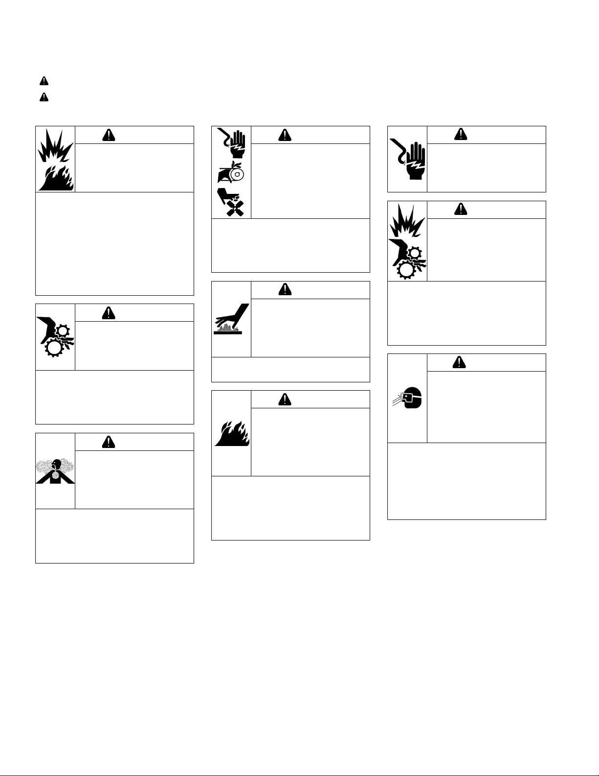
SAFETY PRECAUTIONS
WARNING: A hazard that could result in death, serious injury, or substantial property damage.
CAUTION: A hazard that could result in minor personal injury or property damage.
NOTE: is used to notify people of important installation, operation, or maintenance information.
WARNING
Explosive Fuel can cause
res and severe burns.
Do not ll fuel tank while
engine is hot or running.
Gasoline is extremely ammable
and its vapors can explode if
ignited. Store gasoline only in
approved containers, in well
ventilated, unoccupied buildings,
away from sparks or ames.
Spilled fuel could ignite if it comes
in contact with hot parts or sparks
from ignition. Never use gasoline
as a cleaning agent.
WARNING
Rotating Parts can cause
severe injury.
Stay away while engine
is in operation.
Keep hands, feet, hair, and
clothing away from all moving
parts to prevent injury. Never
operate engine with covers,
shrouds, or guards removed.
WARNING
Carbon Monoxide can
cause severe nausea,
fainting or death.
Avoid inhaling exhaust
fumes.
Engine exhaust gases contain
poisonous carbon monoxide.
Carbon monoxide is odorless,
colorless, and can cause death if
inhaled.
Accidental Starts can
cause severe injury or
death.
Disconnect and ground
spark plug lead(s) before
servicing.
Before working on engine or
equipment, disable engine as
follows: 1) Disconnect spark plug
lead(s). 2) Disconnect negative (–)
battery cable from battery.
Hot Parts can cause
severe burns.
Do not touch engine
while operating or just
after stopping.
Never operate engine with heat
shields or guards removed.
Cleaning Solvents can
cause severe injury or
death.
Use only in well
ventilated areas away
from ignition sources.
Carburetor cleaners and solvents
are extremely ammable. Follow
cleaner manufacturer’s warnings
and instructions on its proper and
safe use. Never use gasoline as a
cleaning agent.
WARNING
WARNING
WARNING
Electrical Shock can
cause injury.
Do not touch wires while
engine is running.
Damaging Crankshaft
and Flywheel can cause
personal injury.
Using improper procedures can
lead to broken fragments. Broken
fragments could be thrown from
engine. Always observe and use
precautions and procedures when
installing ywheel.
Uncoiling Spring can
cause severe injury.
Wear safety goggles or
face protection when
servicing retractable
starter.
Retractable starters contain a
powerful, recoil spring that is
under tension. Always wear safety
goggles when servicing retractable
starters and carefully follow
instructions in Retractable Starter
for relieving spring tension.
CAUTION
CAUTION
WARNING
2
KohlerEngines.com 17 690 01 Rev. E
Page 3
Maintenance
MAINTENANCE INSTRUCTIONS
WARNING
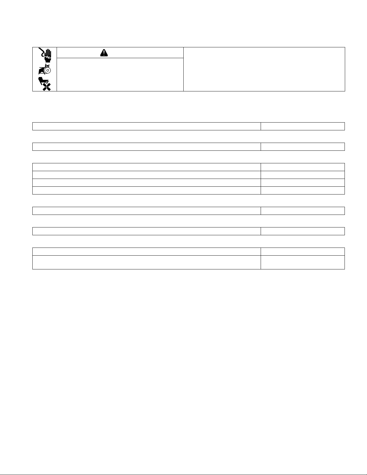
Accidental Starts can cause severe injury or
death.
Disconnect and ground spark plug lead(s)
before servicing.
Normal maintenance, replacement or repair of emission control devices and systems may be performed by any repair
establishment or individual; however, warranty repairs must be performed by a Kohler authorized dealer.
MAINTENANCE SCHEDULE
After rst 5 Hours
● Change oil. Lubrication System
Every 50 Hours or Annually
● Service/replace Quad-Clean
precleaner. Air Cleaner/Intake
™
Every 100 Hours or Annually¹
● Clean low-prole air cleaner element. Air Cleaner/Intake
● Change oil. Lubrication System
● Clean cooling areas. Air Cleaner/Intake
● Replace spark plug and set gap. Electrical System
Before working on engine or equipment, disable engine as
follows: 1) Disconnect spark plug lead(s). 2) Disconnect
negative (–) battery cable from battery.
Every 200 Hours²
● Check and adjust valve clearance when engine is cold. Reassembly
Every 200 Hours
● Replace Quad-Clean
air cleaner element. Air Cleaner/Intake
™
Every 300 Hours
● Replace low-prole air cleaner element. Air Cleaner/Intake
● Check fuel lters (tank outlet lter and in-line lter) clean or replace if needed (if
equipped).
1
Perform these procedures more frequently under severe, dusty, dirty conditions.
2
Have a Kohler authorized dealer perform this service.
Fuel System
REPAIRS/SERVICE PARTS
Kohler genuine service parts can be purchased from Kohler authorized dealers. To nd a local Kohler authorized
dealer visit KohlerEngines.com or call 1-800-544-2444 (U.S. and Canada).
17 690 01 Rev. E KohlerEngines.com
3
Page 4
Maintenance
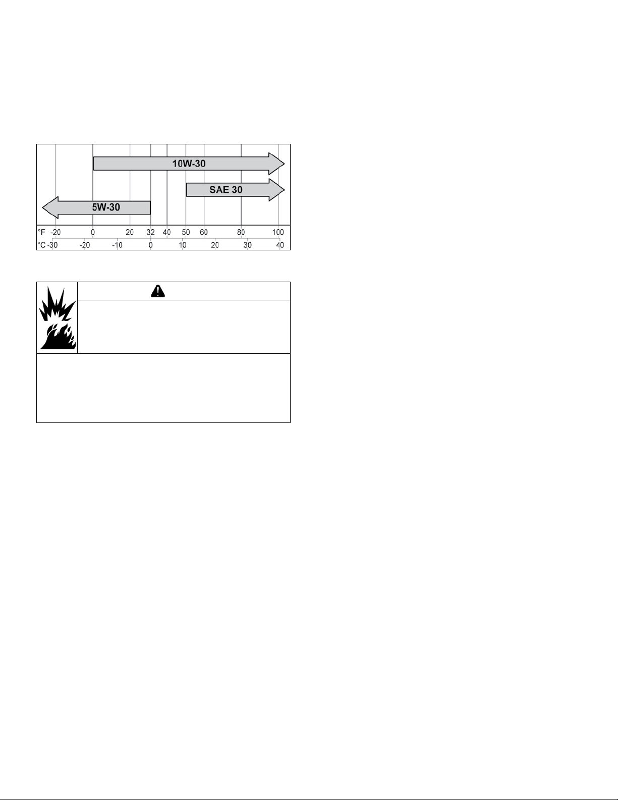
OIL RECOMMENDATIONS
We recommend use of Kohler oils for best performance.
Other high-quality detergent oils (including synthetic)
of API (American Petroleum Institute) service class SJ
or higher are acceptable. Select viscosity based on
air temperature at time of operation as shown in table
below.
FUEL RECOMMENDATIONS
WARNING
Explosive Fuel can cause res and severe
burns.
Do not ll fuel tank while engine is hot or
running.
STORAGE
If engine will be out of service for 2 months or more
follow procedure below.
1. Add Kohler PRO Series fuel treatment or equivalent
to fuel tank. Run engine 2-3 minutes to get stabilized
fuel into fuel system (failures due to untreated fuel
are not warrantable).
2. Change oil while engine is still warm from operation.
Remove spark plug(s) and pour about 1 oz. of
engine oil into cylinder(s). Replace spark plug(s) and
crank engine slowly to distribute oil.
3. Disconnect negative (-) battery cable.
4. Store engine in a clean, dry place.
Gasoline is extremely ammable and its vapors can
explode if ignited. Store gasoline only in approved
containers, in well ventilated, unoccupied buildings,
away from sparks or ames. Spilled fuel could ignite
if it comes in contact with hot parts or sparks from
ignition. Never use gasoline as a cleaning agent.
NOTE: E15, E20 and E85 are NOT approved and
should NOT be used; effects of old, stale or
contaminated fuel are not warrantable.
Fuel must meet these requirements:
● Clean, fresh, unleaded gasoline.
● Octane rating of 87 (R+M)/2 or higher.
● Research Octane Number (RON) 90 octane minimum.
● Gasoline up to 10% ethyl alcohol, 90% unleaded is
acceptable.
● Methyl Tertiary Butyl Ether (MTBE) and unleaded
gasoline blend (max 15% MTBE by volume) are
approved.
● Do not add oil to gasoline.
● Do not overll fuel tank.
● Do not use gasoline older than 30 days.
4
KohlerEngines.com 17 690 01 Rev. E
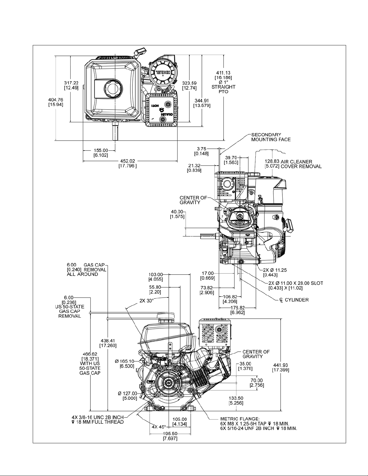
Page 5
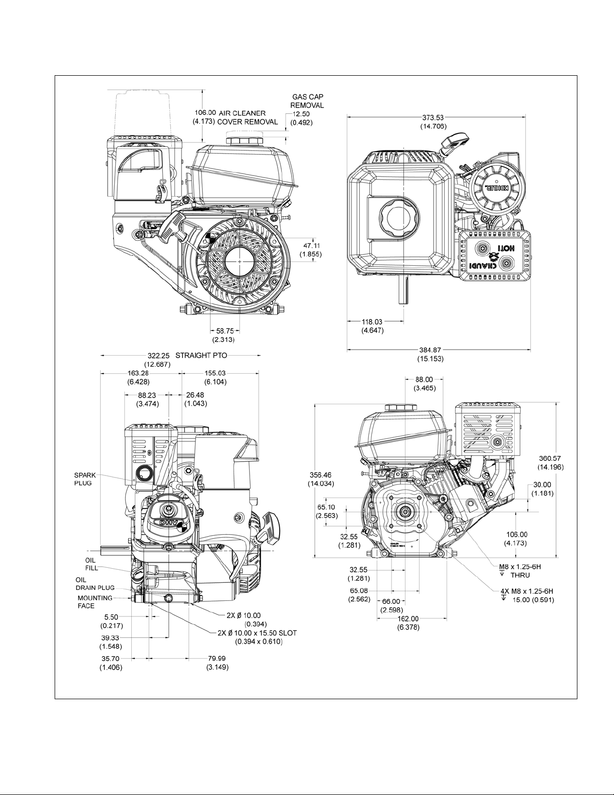
CH260/CH270 Engine Dimensions
Specications
Dimensions in millimeters.
Inch equivalents shown in [ ].
17 690 01 Rev. E KohlerEngines.com
5
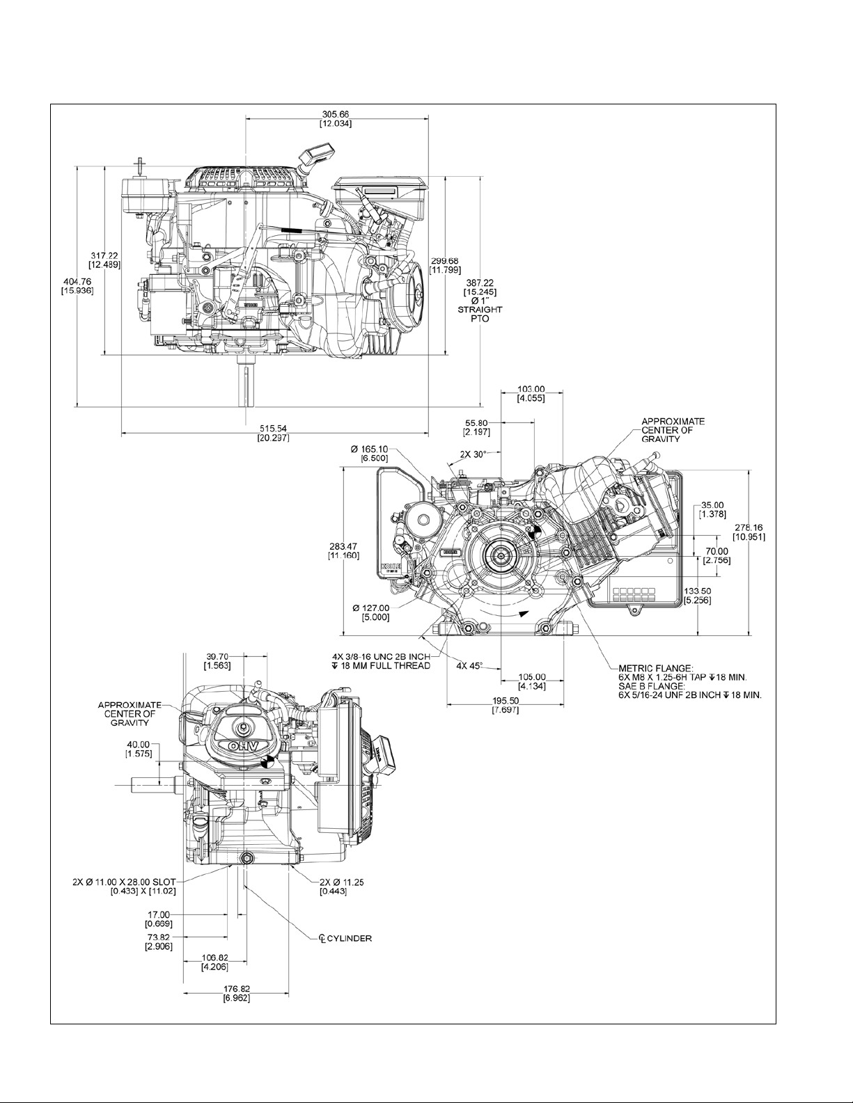
Page 6
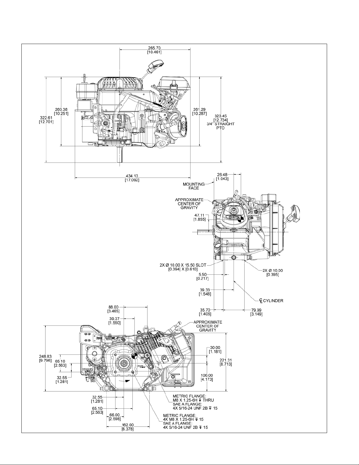
Specications
CH260/CH270 Engine Dimensions
Dimensions in millimeters.
Inch equivalents shown in [ ].
6
KohlerEngines.com 17 690 01 Rev. E
Page 7
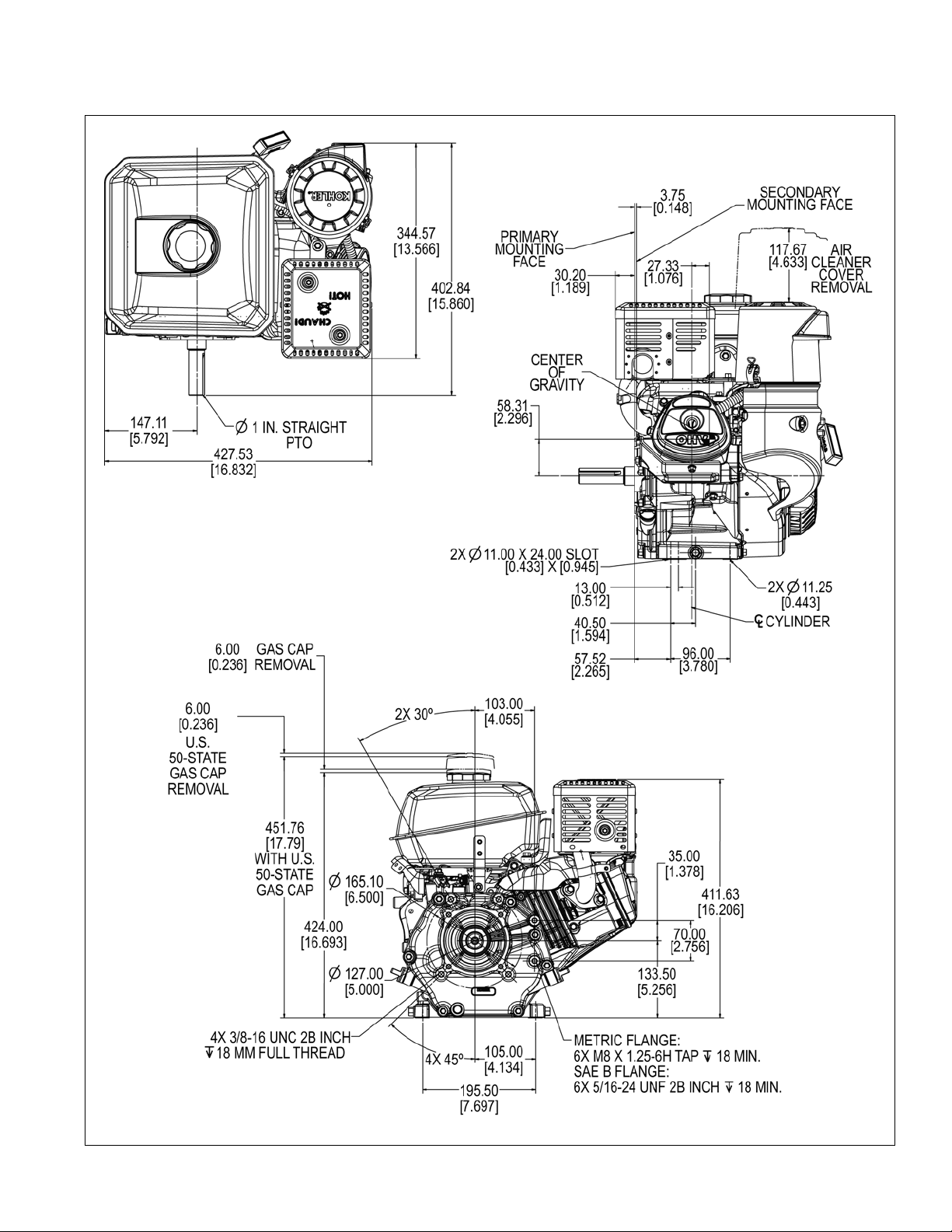
CH395 Engine Dimensions
Specications
Dimensions in millimeters.
Inch equivalents shown in [ ].
17 690 01 Rev. E KohlerEngines.com
7
Page 8
Specications
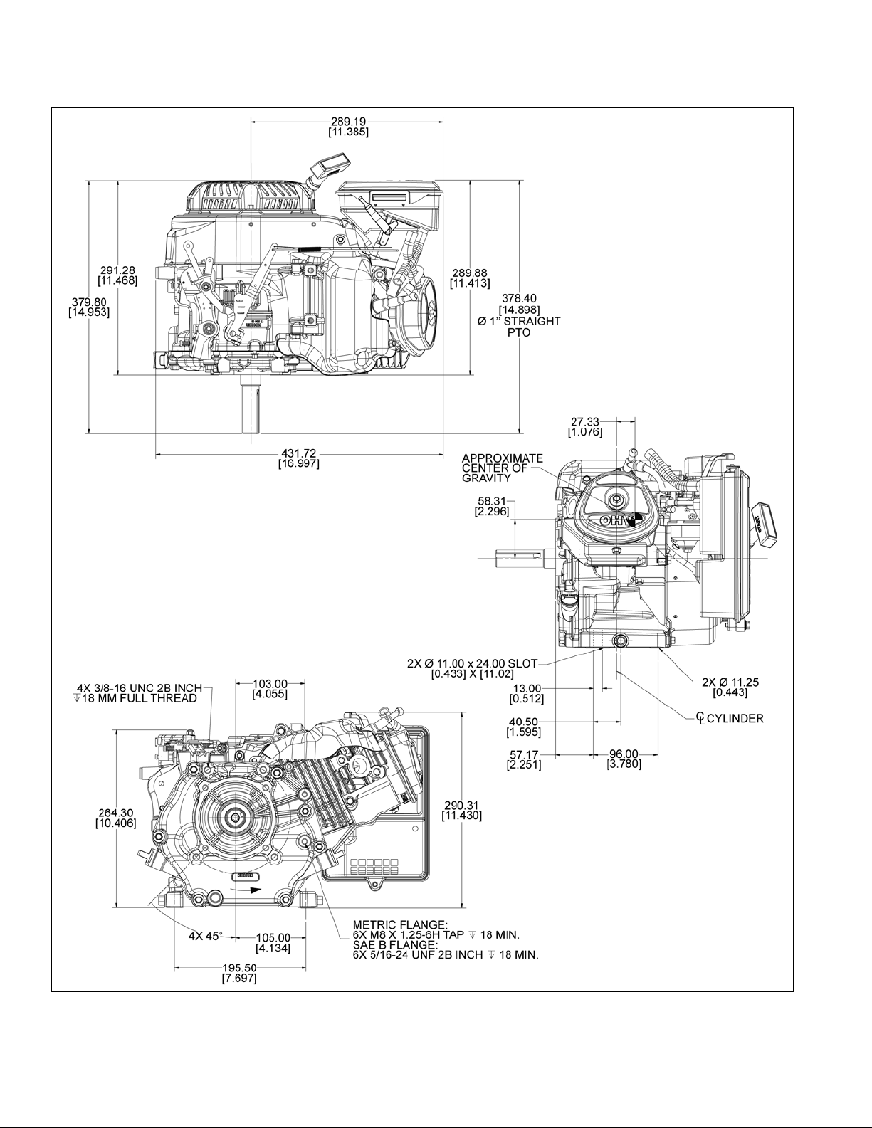
CH395 Engine Dimensions
Dimensions in millimeters.
Inch equivalents shown in [ ].
8
KohlerEngines.com 17 690 01 Rev. E
Page 9
CH440 Engine Dimensions
Specications
Dimensions in millimeters.
Inch equivalents shown in [ ].
17 690 01 Rev. E KohlerEngines.com
9
Page 10
Specications
CH440 Engine Dimensions
Dimensions in millimeters.
Inch equivalents shown in [ ].
10
KohlerEngines.com 17 690 01 Rev. E
Page 11
Specications
ENGINE IDENTIFICATION NUMBERS
Kohler engine identication numbers (model, specication and serial) should be referenced for efcient repair,
ordering correct parts, and engine replacement.
Model . . . . . . . . . . . . . . . . . . . . . CH260
Command Engine
Horizontal Shaft
Numerical Designation
Specication . . . . . . . . . . . . . . . CH260-0001
Serial . . . . . . . . . . . . . . . . . . . . . 3923500328
Year Manufactured Code Factory Code
Code Year
39 2009
40 2010
41 2011
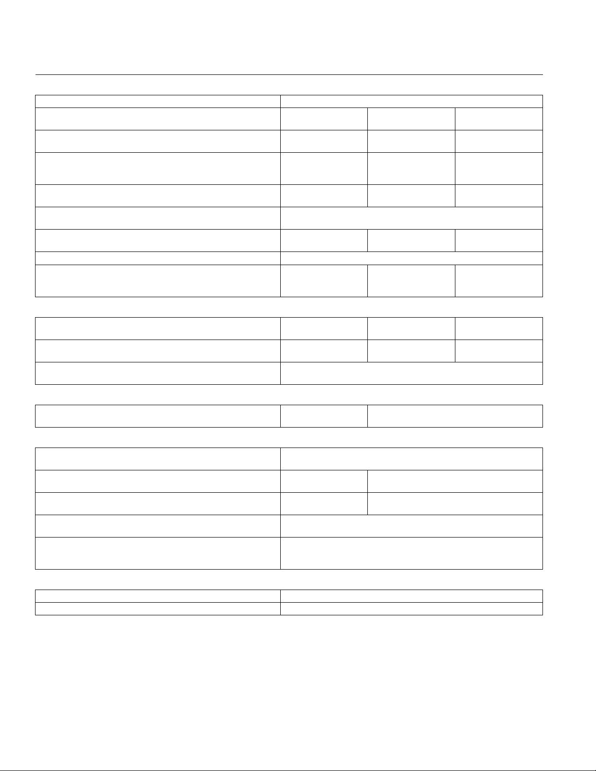
GENERAL SPECIFICATIONS
3,6
CH260/CH270 CH395 CH440
Bore 70 mm (2.8 in.) 78 mm (3.1 in.) 89 mm (3.5 in.)
Stroke 54 mm (2.1 in.) 58 mm (2.3 in.) 69 mm (2.7 in.)
Displacement 208 cc
(12.7 cu. in.)
Oil Capacity (rell) 0.6 L
(0.63 U.S. qt.)
Maximum Angle of Operation (@ full oil level)
TORQUE SPECIFICATIONS
3,5
4
CH260/CH270 CH395 CH440
277 cc
(16.9 cu. in.)
1.1 L
(1.16 U.S. qt.)
25°
429 cc
(24.7 cu. in.)
1.3 L
(1.37 U.S. qt.)
Air Cleaner
Quad-Clean
Air Cleaner Base Mounting Screw 8.0 N·m (71 in. lb.)
™
Low-Prole Air Cleaner Base Mounting Screw 6.7 N·m (59 in. lb.)
Blower Housing and Sheet Metal
M6 Screw 10 N·m (89 in. lb.)
M6 Nut 8.0 N·m (71 in. lb.)
Carburetor
Stud 10 N·m (89 in. lb.)
Primary Nut 8 N·m (71 in. lb.)
Intake Cover Nut 4 N·m (35 in. lb.)
Intake Cover Screw 1.3 N·m (12 in. lb.)
Connecting Rod
Cap Fastener (torque in increments) 12 N·m
20 N·m (177 in. lb.)
(106 in. lb.)
3
Values are in Metric units. Values in parentheses are English equivalents.
4
Exceeding maximum angle of operation may cause engine damage from insufcient lubrication.
5
Lubricate threads with engine oil prior to assembly.
6
Any and all horsepower (hp) references by Kohler are Certied Power Ratings and per SAE J1940 & J1995 hp
standards. Details on Certied Power Ratings can be found at KohlerEngines.com.
17 690 01 Rev. E KohlerEngines.com
11
Page 12
Specications
TORQUE SPECIFICATIONS
3,5
CH260/CH270 CH395 CH440
Crankcase
Oil Drain Plug 18 N·m (13 ft. lb.)
Closure Plate Screw 24 N·m (212 in. lb.)
Cylinder Head
Fastener (torque in 2 increments) First to 12 N·m
(106 in. lb.)
First to 18 N·m (159 in. lb.)
Finally to 36 N·m (319 in. lb.)
Finally to 24 N·m
(212 in. lb.)
Electric Starter
Mounting Screw 24 N·m (212 in. lb.)
Flywheel
Retaining Nut 74 N·m
113 N·m (1000 in. lb.)
(655 in. lb.)
Fuel Tank
Mounting Nut 24 N·m (212 in. lb.)
Mounting Screw 24 N·m (212 in. lb.)
Inlet Fitting 1.5 N·m (13 in. lb.)
Governor
Lever Nut 12 N·m (106 in. lb.)
Throttle Control Lever Nut 9 N·m (80 in. lb.)
Ignition
Spark Plug 27 N·m (20 ft. lb.)
Module Fastener 10 N·m (89 in. lb.)
Oil Sentry
Oil Sentry
Oil Sentry
Float Switch Screw 8 N·m (71 in. lb.)
™
Module Screw 3.5 N·m (31 in. lb.)
™
Wire Lead Nut 10 N·m (89 in. lb.)
™
Mufer
Exhaust Screw
M8
M10
24 N·m (212 in. lb.)
---
---
35 N·m (310 in. lb.)
Mufer Shield Screw
M6 8 N·m (71 in. lb.)
M4 2 N·m (18 in. lb.) 3.5 N·m (31 in. lb.)
Spark Arrestor Screw M5 3.5 N·m (31 in. lb.)
Retractable Starter
Cover Screw 5.4 N·m (48 in. lb.)
Center Screw 10 N·m (89 in. lb.)
Rocker Arm
Stud 13.6 N·m (120 in. lb.)
Pivot Jam Nut 10 N·m (89 in. lb.)
3
Values are in Metric units. Values in parentheses are English equivalents.
5
Lubricate threads with engine oil prior to assembly.
12
KohlerEngines.com 17 690 01 Rev. E
Page 13

Specications
TORQUE SPECIFICATIONS
3,5
CH260/CH270 CH395 CH440
Valve Cover
Fastener 10 N·m (89 in. lb.)
CLEARANCE SPECIFICATIONS
3
CH260/CH270 CH395 CH440
Camshaft
Running Clearance 0.007/0.043 mm
(0.0003/0.0017 in.)
0.016/0.052 mm
(0.0006/0.0020 in.)
Bore I.D.
New 13.991/14.009 mm
16.000/16.018 mm (0.6300/0.6310 in.)
(0.5508/0.5515 in.)
Max. Wear Limit 14.018 mm
16.068 mm (0.6289 in.)
(0.5519 in.)
Camshaft Bearing Surface O.D.
New 13.975 mm
15.975 mm (0.63 in.)
(0.55 in.)
Max. Wear Limit 13.90 mm
15.90 mm (0.626 in.)
(0.547 in.)
Cam Lobe Prole (minimum dimension, measured from
base circle to top of lobe)
Intake - New 31.966 mm
(1.259 in.)
Max. Wear Limit 31.72 mm
(1.249 in.)
Exhaust - New 31.966 mm
(1.259 in.)
Max. Wear Limit 31.72 mm
(1.249 in.)
32.544 mm
(1.281 in.)
32.11 mm
(1.264 in.)
32.256 mm
(1.270 in.)
31.79 mm
(1.252 in.)
33.266 mm
(1.310 in.)
32.26 mm
(1.270 in.)
32.642 mm
(1.285 in.)
31.61 mm
(1.245 in.)
Connecting Rod
Crankpin End I.D. @ 21°C (70°F)
New 30.021/30.026 mm
(1.1819/1.1821 in.)
Max. Wear Limit 30.08 mm
(1.184 in.)
33.020/33.030 mm
(1.3000/1.3004 in.)
33.07 mm
(1.302 in.)
37.08 mm
(1.460 in.)
Connecting Rod-to-Crankpin Side Clearance
New 0.58/0.60 mm
(0.023/0.024 in.)
Max. Wear Limit 1.10 mm
(0.043 in.)
Connecting Rod-to-Piston Pin Running Clearance 0.008/0.025 mm
(0.0003/0.0010 in.)
0.73 mm
(0.029 in.)
1.36 mm
(0.054 in.)
0.006/0.028 mm
(0.0002/0.0011 in.)
0.56 mm
(0.022 in.)
1.06 mm
(0.042 in.)
0.008/0.025 mm
(0.0003/0.0010 in.)
Piston Pin End I.D. @ 21°C (70°F)
New 18.010/18.015 mm
(0.7091/0.7093 in.)
18.004/18.020 mm
(0.7088/0.7094 in.)
20.000/20.008 mm
(0.7874/0.7874 in.)
Max. Wear Limit 18.08 mm (0.712 in.) 20.05 mm
(0.789 in.)
Crankcase
Governor Cross Shaft Bore I.D.
New
Max. Wear Limit 6.037 mm
6.000/6.024 mm
(0.2362/0.2372 in.)
8.000/8.024 mm (0.3150/0.3159 in.)
8.074 mm (0.7118 in.)
(0.2377 in.)
3
Values are in Metric units. Values in parentheses are English equivalents.
17 690 01 Rev. E KohlerEngines.com
13
Page 14
Specications
CLEARANCE SPECIFICATIONS
3
CH260/CH270 CH395 CH440
Crankshaft
End Play (free) 0.0508/0.254 mm (0.002/0.010 in.)
Ball Bearing Internal Clearance 0.003/0.025 mm
(0.0001/0.0010 in.)
Crankshaft O.D. (new) 24.975/24.989 mm
(0.9833/0.9838 in.)
0.005/0.020 mm
(0.0002/0.0008 in.)
29.975/29.989 mm
(1.1801/1.1807 in.)
0.006/0.020 mm
(0.0002/0.0008 in.)
34.975/34.989 mm
(1.3770/1.3775 in.)
Connecting Rod Journal O.D.
New 30.020/30.030 mm
(1.1819/1.1823 in.)
Max. Wear Limit 30.08 mm
(1.1842 in.)
Max. Taper
Max. Out-of-Round
Width 24.5/24.9 mm
(0.9646/0.9803 in.)
32.975/32.985 mm
(1.2982/1.2986 in.)
32.92 mm
(1.2961 in.)
2.5 microns (0.0001 in.)
12.7 microns (0.0005 in.)
30.30/30.36 mm
(1.1930/1.1953 in.)
36.975/36.985 mm
(1.4557/1.4561 in.)
28.30/28.36 mm
(1.1142/1.1165 in.)
Runout (either end) 0.025 mm (0.001 in.)
Main Bearing I.D. (Crankcase/Closure Plate)
New (installed) 24.992/25.000 mm
(0.9839/0.9842 in.)
29.990/30.000 mm
1.1807/1.1811 in.)
34.990/35.000 mm
(1.3776/1.3780 in.)
Cylinder Bore
Bore I.D.
New
Max. Wear Limit 70.200 mm
Max. Out-of-Round
Max. Taper
70.027/70.035 mm
(2.757/2.757 in.)
(2.764 in.)
77.98/78.02 mm
(3.0701/3.0717 in.)
78.185 mm
(3.0781 in.)
12.7 microns (0.0005 in.)
12.7 microns (0.0005 in.)
89.00/89.02 mm
(3.5039/3.5045 in.)
36.92 mm
(1.4535 in.)
89.185 mm
(3.5112 in.)
Cylinder Head
Max. Out-of-Flatness 0.08 mm
0.1 mm (0.004 in.)
(0.003 in.)
Governor
Governor Cross Shaft -to-Crankcase Running
0.020/0.069 mm (0.0008/0.0027 in.)
Clearance
Governor Cross Shaft O.D.
New
Max. Wear Limit 5.942 mm
5.955/5.980 mm
(0.2344/0.2354 in.)
7.955/7.980 mm
(0.3132/0.3142 in.)
7.900 mm (0.3110 in.)
(0.2339 in.)
Governor Gear Shaft -to-Governor Gear Running
0.022/0.134 mm (0.0009/0.0053 in.)
Clearance
Governor Gear Shaft O.D.
New
Max. Wear Limit
6.016/6.028 mm (0.2368/0.2373 in.)
6.003 mm (0.2363 in.)
Ignition
Spark Plug Gap 0.76 mm (0.030 in.)
Module Air Gap 0.254 mm (0.010 in.)
3
Values are in Metric units. Values in parentheses are English equivalents.
14
KohlerEngines.com 17 690 01 Rev. E
Page 15

Specications
CLEARANCE SPECIFICATIONS
3
CH260/CH270 CH395 CH440
Piston, Piston Rings, and Piston Pin
Piston-to-Piston Pin Running Clearance 0.009/0.016 mm
0.002/0.016 mm (0.0001/0.0006 in.)
(0.0003/0.0006 in.)
Piston Pin Bore I.D.
New 18.004/18.005 mm
(0.7088/0.7089 in.)
18.000/18.008 mm
(0.7087/0.7090 in.)
20.000/20.008 mm
(0.7874/0.7877 in.)
Max. Wear Limit 18.05 mm (0.7106 in.) 20.05 mm
(0.7894 in.)
Piston Pin O.D.
New 17.992/17.995 mm (0.7083/0.7084 in.)
19.992/19.998 mm
(0.7871/0.7873 in.)
Max. Wear Limit 17.95 mm (0.7067 in.) 19.95 mm
(0.7854 in.)
Top and Center Compression Ring Side Clearance
New Bore 0.04 mm
(0.002 in.)
Used Bore (Max.) 0.15 mm
(0.006 in.)
Top Compression Ring End Gap
New Bore
0.325/0.400 mm
(0.013/0.016 in.)
0.07 mm
(0.003 in.)
0.11 mm
(0.004 in.)
0.045 mm
(0.0018 in.)
0.10 mm
(0.004 in.)
0.250/0.400 mm (0.010/0.016 in.)
Used Bore (Max.) 1.00 mm (0.039 in.)
Center Compression Ring End Gap
New Bore
Used Bore (Max.) 1.00 mm
0.325/0.400 mm
(0.013/0.016 in.)
0.650/0.800 mm
(0.026/0.032 in.)
1.50 mm (0.059 in.)
0.640/0.800 mm
(0.025/0.032 in.)
(0.039 in.)
Oil Control Ring-to-Groove Side Clearance 0.05/0.19 mm (0.0019/0.0075 in.) 0.09/0.15 mm
(0.0035/0.0059 in.)
Piston Thrust Face O.D.
New 69.970/69.960 mm
(2.755/2.754 in.)
Max. Wear Limit 69.82 mm
(2.749 in.)
Piston Thrust Face-to-Cylinder Bore Running
Clearance
0.057/0.075 mm
(0.002/0.003 in.)
77.955/77.975 mm
7
(3.071/3.070 in.)
77.82 mm
(3.064 in.)
0.033/0.067 mm
7
(0.001/0.003 in.)
88.955/88.975 mm
8
(3.502/3.503 in.)
88.82 mm
(3.497 in.)
0.025/0.060 mm
8
(0.001/0.002 in.)
9
9
3
Values are in Metric units. Values in parentheses are English equivalents.
7
Measure 21.8-22.2 mm (0.8583-0.8740 in.) above bottom of piston skirt at right angles to piston pin.
8
Measure 17.8-18.2 mm (0.7008-0.7165 in.) above bottom of piston skirt at right angles to piston pin.
9
Measure 29.8-30.2 mm (1.1732-1.1890 in.) above bottom of piston skirt at right angles to piston pin.
17 690 01 Rev. E KohlerEngines.com
15
Page 16

Specications
CLEARANCE SPECIFICATIONS
3
CH260/CH270 CH395 CH440
Valves and Valve Lifters
Intake Valve Stem-to-Valve Guide Running Clearance 0.038/0.065 mm
0.025/0.055 mm (0.0010/0.0022 in.)
(0.0015/0.0026 in.)
Exhaust Valve Stem-to-Valve Guide Running Clearance 0.085/0.112 mm
0.040/0.07 mm (0.0016/0.0026 in.)
(0.0033/0.0044 in.)
Intake Valve Stem O.D.
New
5.50 mm
(0.217 in.)
Max. Wear Limit 5.34 mm
(0.210 in.)
Exhaust Valve Stem O.D.
New 5.438 mm
(0.214 in.)
Max. Wear Limit 5.28 mm
(0.208 in.)
Intake Valve Stem to Guide
New 0.024/0.039 mm
0.025/0.055 mm (0.0010/0.0022 in.)
(0.0009/0.0015 in.)
Max. Wear Limit 0.10 mm
(0.0039 in.)
0.13 mm
(0.0051 in.)
Exhaust Valve Stem to Guide
New 0.098/0.112 mm
0.040/0.070 mm (0.0016/0.0028 in.)
(0.0038/0.0044 in.)
Max. Wear Limit 0.12 mm
(0.0047 in.)
Valve Guide Reamer Size
Standard Intake
5.524 mm (0.2175
in.)
0.10 mm
(0.0039 in.)
Standard Exhaust 5.536 mm (0.2179
in.)
Valve Seat Width 0.80 mm (0.0315
1.10 mm (0.0433
in.)
Nominal Valve Face Angle 45°
6.57 mm (0.259 in.)
6.40 mm (0.252 in.)
6.55 mm (0.258 in.)
6.41 mm (0.252 in.)
0.14 mm
(0.0055 in.)
0.11 mm
(0.0043 in.)
6.608 mm (0.2602 in.)
6.608 mm (0.2602 in.)
1.20 mm (0.0472
in.)
in.)
3
Values are in Metric units. Values in parentheses are English equivalents.
16
KohlerEngines.com 17 690 01 Rev. E
Page 17
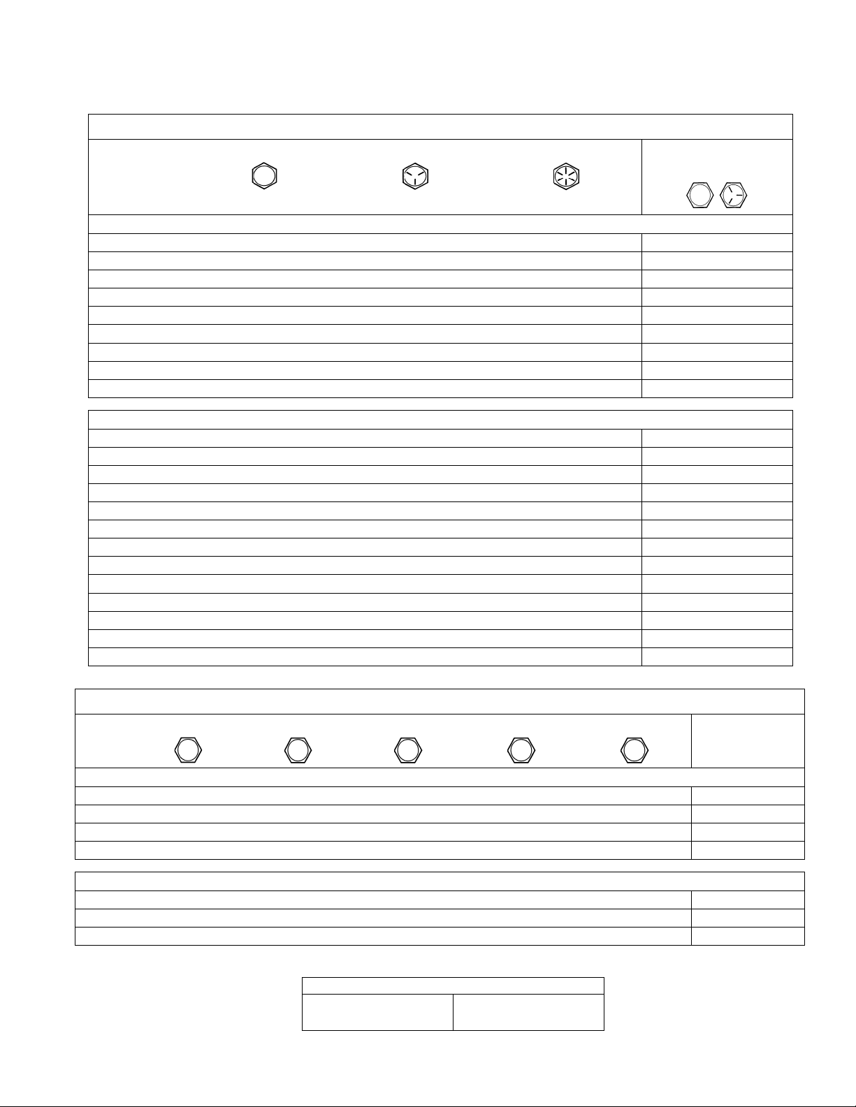
GENERAL TORQUE VALUES
English Fastener Torque Recommendations for Standard Applications
Bolts, Screws, Nuts and Fasteners Assembled Into Cast Iron or Steel
Grade 2 or 5 Fasteners
Size Grade 2 Grade 5 Grade 8
Tightening Torque: N·m (in. lb.) ± 20%
8-32 2.3 (20) 2.8 (25) — 2.3 (20)
10-24 3.6 (32) 4.5 (40) — 3.6 (32)
10-32 3.6 (32) 4.5 (40) — —
1/4-20 7.9 (70) 13.0 (115) 18.7 (165) 7.9 (70)
1/4-28 9.6 (85) 15.8 (140) 22.6 (200) —
5/16-18 17.0 (150) 28.3 (250) 39.6 (350) 17.0 (150)
5/16-24 18.7 (165) 30.5 (270) — —
3/8-16 29.4 (260) — — —
3/8-24 33.9 (300) — — —
Tightening Torque: N·m (ft. lb.) ± 20%
5/16-24 — — 40.7 (30) —
3/8-16 — 47.5 (35) 67.8 (50) —
3/8-24 — 54.2 (40) 81.4 (60) —
7/16-14 47.5 (35) 74.6 (55) 108.5 (80) —
7/16-20 61.0 (45) 101.7 (75) 142.5 (105) —
1/2-13 67.8 (50) 108.5 (80) 155.9 (115) —
1/2-20 94.9 (70) 142.4 (105) 223.7 (165) —
9/16-12 101.7 (75) 169.5 (125) 237.3 (175) —
9/16-18 135.6 (100) 223.7 (165) 311.9 (230) —
5/8-11 149.5 (110) 244.1 (180) 352.6 (260) —
5/8-18 189.8 (140) 311.9 (230) 447.5 (330) —
3/4-10 199.3 (147) 332.2 (245) 474.6 (350) —
3/4-16 271.2 (200) 440.7 (325) 637.3 (470) —
Specications
Into Aluminum
Metric Fastener Torque Recommendations for Standard Applications
Size
4.8
5.8
Property Class
8.8
10.9 12.9
Noncritical
Fasteners
Into Aluminum
Tightening Torque: N·m (in. lb.) ± 10%
M4 1.2 (11) 1.7 (15) 2.9 (26) 4.1 (36) 5.0 (44) 2.0 (18)
M5 2.5 (22) 3.2 (28) 5.8 (51) 8.1 (72) 9.7 (86) 4.0 (35)
M6 4.3 (38) 5.7 (50) 9.9 (88) 14.0 (124) 16.5 (146) 6.8 (60)
M8 10.5 (93) 13.6 (120) 24.4 (216) 33.9 (300) 40.7 (360) 17.0 (150)
Tightening Torque: N·m (ft. lb.) ± 10%
M10 21.7 (16) 27.1 (20) 47.5 (35) 66.4 (49) 81.4 (60) 33.9 (25)
M12 36.6 (27) 47.5 (35) 82.7 (61) 116.6 (86) 139.7 (103) 61.0 (45)
M14 58.3 (43) 76.4 (56) 131.5 (97) 184.4 (136) 219.7 (162) 94.9 (70)
Torque Conversions
N·m = in. lb. x 0.113 in. lb. = N·m x 8.85
N·m = ft. lb. x 1.356 ft. lb. = N·m x 0.737
17 690 01 Rev. E KohlerEngines.com
17
Page 18

Tools and Aids
Certain quality tools are designed to help you perform specic disassembly, repair, and reassembly procedures. By
using these tools, you can properly service engines easier, faster, and safer! In addition, you’ll increase your service
capabilities and customer satisfaction by decreasing engine downtime.
Here is a list of tools and their source.
SEPARATE TOOL SUPPLIERS
Kohler Tools
Contact your local Kohler source of
supply.
TOOLS
Description Source/Part No.
Alcohol Content Tester
For testing alcohol content (%) in reformulated/oxygenated fuels.
Camshaft Endplay Plate
For checking camshaft endplay.
Camshaft Seal Protector (Aegis)
For protecting seal during camshaft installation.
Cylinder Leakdown Tester
For checking combustion retention and if cylinder, piston, rings, or valves are worn.
Individual component available:
Adapter 12 mm x 14 mm (Required for leakdown test on XT-6 engines)
Dealer Tool Kit (Domestic)
Complete kit of Kohler required tools.
Components of 25 761 39-S
Ignition System Tester
Cylinder Leakdown Tester
Oil Pressure Test Kit
Rectier-Regulator Tester (120 V AC/60Hz)
Dealer Tool Kit (International)
Complete kit of Kohler required tools.
Components of 25 761 42-S
Ignition System Tester
Cylinder Leakdown Tester
Oil Pressure Test Kit
Rectier-Regulator Tester (240 V AC/50Hz)
Digital Vacuum/Pressure Tester
For checking crankcase vacuum.
Individual component available:
Rubber Adapter Plug
Electronic Fuel Injection (EFI) Diagnostic Software
For Laptop or Desktop PC.
EFI Service Kit
For troubleshooting and setting up an EFI engine.
Components of 24 761 01-S
Fuel Pressure Tester
Noid Light
90° Adapter
In-line "T" Fitting
Code Plug, Red Wire
Code Plug, Blue Wire
Shrader Valve Adapter Hose
Flywheel Holding Tool (CS)
For holding ywheel of CS series engines.
Flywheel Puller
For properly removing ywheel from engine.
Flywheel Strap Wrench
For holding ywheel during removal.
SE Tools
415 Howard St.
Lapeer, MI 48446
Phone 810-664-2981
Toll Free 800-664-2981
Fax 810-664-8181
Design Technology Inc.
768 Burr Oak Drive
Westmont, IL 60559
Phone 630-920-1300
Fax 630-920-0011
Kohler 25 455 11-S
SE Tools KLR-82405
SE Tools KLR-82417
Kohler 25 761 05-S
Design Technology Inc.
DTI-731-03
Kohler 25 761 39-S
Kohler 25 455 01-S
Kohler 25 761 05-S
Kohler 25 761 06-S
Kohler 25 761 20-S
Kohler 25 761 42-S
Kohler 25 455 01-S
Kohler 25 761 05-S
Kohler 25 761 06-S
Kohler 25 761 41-S
Design Technology Inc.
DTI-721-01
Design Technology Inc.
DTI-721-10
Kohler 25 761 23-S
Kohler 24 761 01-S
Design Technology Inc.
DTI-019
DTI-021
DTI-023
DTI-035
DTI-027
DTI-029
DTI-037
SE Tools KLR-82407
SE Tools KLR-82408
SE Tools KLR-82409
18 17 690 01 Rev. EKohlerEngines.com
Page 19

Tools and Aids
TOOLS
Description Source/Part No.
Hydraulic Valve Lifter Tool
For removing and installing hydraulic lifters.
Ignition System Tester
For testing output on all systems, including CD.
Inductive Tachometer (Digital)
For checking operating speed (RPM) of an engine.
Offset Wrench (K and M Series)
For removing and reinstalling cylinder barrel retaining nuts.
Oil Pressure Test Kit
For testing/verifying oil pressure on pressure lubricated engines.
Radiator Tester
For pressure testing radiator and cap on Aegis liquid-cooled engines.
Rectier-Regulator Tester (120 volt current)
Rectier-Regulator Tester (240 volt current)
For testing rectier-regulators.
Components of 25 761 20-S and 25 761 41-S
CS-PRO Regulator Test Harness
Special Regulator Test Harness with Diode
Spark Advance Module (SAM) Tester
For testing SAM (ASAM and DSAM) on engines with SMART-SPARK
.
™
Starter Servicing Kit (All Starters)
For removing and reinstalling drive retaining rings and brushes.
Individual component available:
Starter Brush Holding Tool (Solenoid Shift)
Triad/OHC Timing Tool Set
For holding cam gears and crankshaft in timed position while installing timing belt.
Valve Guide Reamer (K and M Series)
For properly sizing valve guides after installation.
Valve Guide Reamer O.S. (Command Series)
For reaming worn valve guides to accept replacement oversize valves. Can be used
in low-speed drill press or with handle below for hand reaming.
Reamer Handle
For hand reaming using Kohler 25 455 12-S reamer.
Valve Guide Service Kit (Courage, Aegis, Command, OHC)
For servicing worn valve guides.
Kohler 25 761 38-S
Kohler 25 455 01-S
Design Technology Inc.
DTI-110
Kohler 52 455 04-S
Kohler 25 761 06-S
Kohler 25 455 10-S
Kohler 25 761 20-S
Kohler 25 761 41-S
Design Technology Inc.
DTI-031
DTI-033
Kohler 25 761 40-S
SE Tools KLR-82411
SE Tools KLR-82416
Kohler 28 761 01-S
Design Technology Inc.
DTI-K828
Kohler 25 455 12-S
Design Technology Inc.
DTI-K830
SE Tools KLR-82415
AIDS
Description Source/Part No.
Camshaft Lubricant (Valspar ZZ613) Kohler 25 357 14-S
Dielectric Grease (GE/Novaguard G661) Kohler 25 357 11-S
Dielectric Grease Loctite
®
51360
Kohler Electric Starter Drive Lubricant (Inertia Drive) Kohler 52 357 01-S
Kohler Electric Starter Drive Lubricant (Solenoid Shift) Kohler 52 357 02-S
RTV Silicone Sealant
Loctite
Only oxime-based, oil resistant RTV sealants, such as those listed, are approved
®
5900® Heavy Body in 4 oz. aerosol dispenser.
for use. Loctite® Nos. 5900® or 5910® are recommended for best sealing
characteristics.
Kohler 25 597 07-S
Loctite® 5910
®
Loctite® Ultra Black 598™
Loctite® Ultra Blue 587™
Loctite® Ultra Copper 5920™
Spline Drive Lubricant Kohler 25 357 12-S
1917 690 01 Rev. E KohlerEngines.com
Page 20
Tools and Aids
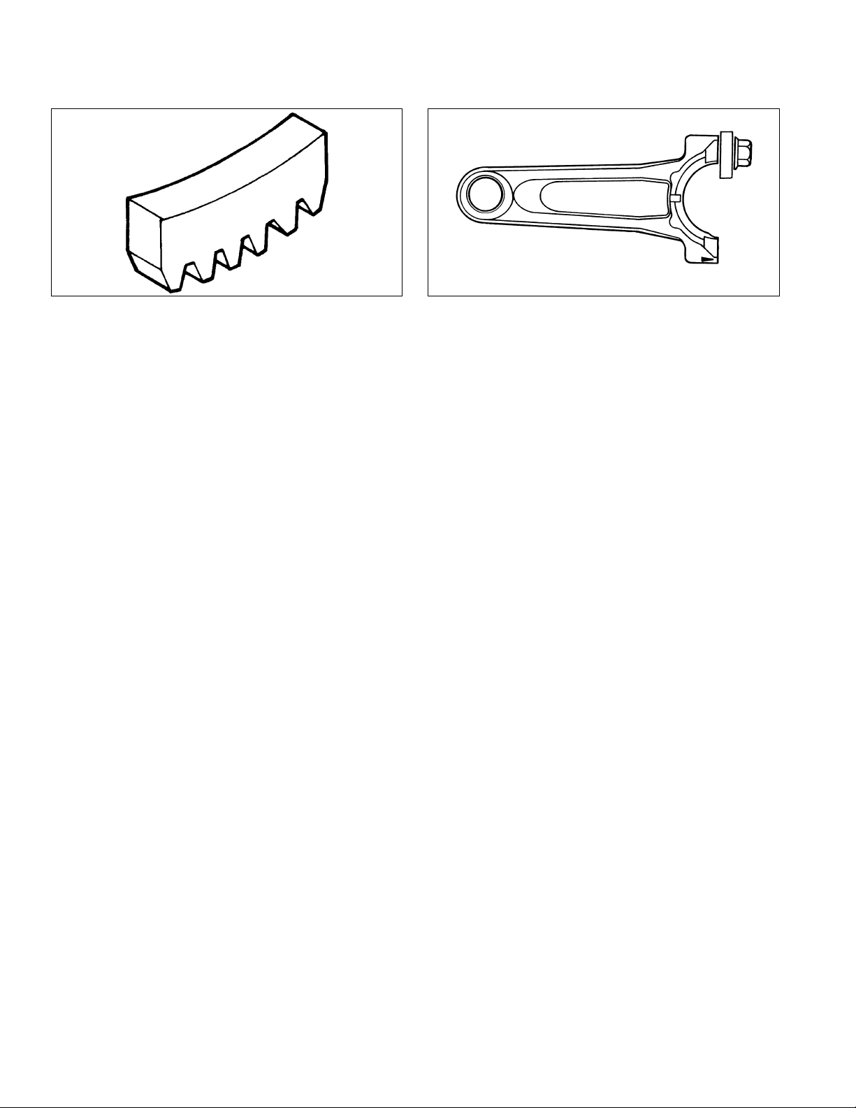
FLYWHEEL HOLDING TOOL ROCKER ARM/CRANKSHAFT TOOL
A ywheel holding tool can be made out of an old junk
ywheel ring gear and used in place of a strap wrench.
1. Using an abrasive cut-off wheel, cut out a six tooth
segment of ring gear as shown.
2. Grind off any burrs or sharp edges.
3. Invert segment and place it between ignition bosses
on crankcase so tool teeth engage ywheel ring
gear teeth. Bosses will lock tool and ywheel in
position for loosening, tightening, or removing with a
puller.
A spanner wrench to lift rocker arms or turn crankshaft
may be made out of an old junk connecting rod.
1. Find a used connecting rod from a 10 HP or larger
engine. Remove and discard rod cap.
2. Remove studs of a Posi-Lock rod or grind off
aligning steps of a Command rod, so joint surface is
at.
3. Find a 1 in. long capscrew with correct thread size to
match threads in connecting rod.
4. Use a at washer with correct I.D. to slip on
capscrew and approximately 1 in. O.D. Assemble
capscrew and washer to joint surface of rod.
20 17 690 01 Rev. EKohlerEngines.com
Page 21

Troubleshooting
TROUBLESHOOTING GUIDE
When troubles occur, be sure to check simple causes which, at rst, may seem too obvious to be considered. For
example, a starting problem could be caused by an empty fuel tank.
Some general common causes of engine troubles are listed below and vary by engine specication. Use these to
locate causing factors.
Engine Cranks But Will Not Start
● Battery connected backwards.
● Blown fuse.
● Carburetor solenoid malfunction.
● Choke not closing.
● Clogged fuel line or fuel lter.
● Diode in wiring harness failed in open circuit mode.
● DSAI or DSAM malfunction.
● Empty fuel tank.
● Faulty electronic control unit.
● Faulty ignition coil(s).
● Faulty spark plug(s).
● Fuel pump malfunction-vacuum hose clogged or
leaking.
● Fuel shut-off valve closed.
● Ignition module(s) faulty or improperly gapped.
● Insufcient voltage to electronic control unit.
● Interlock switch is engaged or faulty.
● Key switch or kill switch in OFF position.
● Low oil level.
● Quality of fuel (dirt, water, stale, mixture).
● SMART-SPARKTM malfunction.
● Spark plug lead(s) disconnected.
Engine Starts But Does Not Keep Running
● Faulty carburetor.
● Faulty cylinder head gasket.
● Faulty or misadjusted choke or throttle controls.
● Fuel pump malfunction-vacuum hose clogged or
leaking.
● Intake system leak.
● Loose wires or connections that intermittently ground
ignition kill circuit.
● Quality of fuel (dirt, water, stale, mixture).
● Restricted fuel tank cap vent.
Engine Starts Hard
● Clogged fuel line or fuel lter.
● Engine overheated.
● Faulty ACR mechanism.
● Faulty or misadjusted choke or throttle controls.
● Faulty spark plug(s).
● Flywheel key sheared.
● Fuel pump malfunction-vacuum hose clogged or
leaking.
● Interlock switch is engaged or faulty.
● Loose wires or connections that intermittently ground
ignition kill circuit.
● Low compression.
● Quality of fuel (dirt, water, stale, mixture).
● Weak spark.
Engine Will Not Crank
● Battery is discharged.
● Faulty electric starter or solenoid.
● Faulty key switch or ignition switch.
● Interlock switch is engaged or faulty.
● Loose wires or connections that intermittently ground
ignition kill circuit.
● Pawls not engaging in drive cup.
● Seized internal engine components.
Engine Runs But Misses
● Carburetor adjusted incorrectly.
● Engine overheated.
● Faulty spark plug(s).
● Ignition module(s) faulty or improperly gapped.
● Incorrect crankshaft position sensor air gap.
● Interlock switch is engaged or faulty.
● Loose wires or connections that intermittently ground
ignition kill circuit.
● Quality of fuel (dirt, water, stale, mixture).
● Spark plug lead(s) disconnected.
● Spark plug lead boot loose on plug.
● Spark plug lead loose.
Engine Will Not Idle
● Engine overheated.
● Faulty spark plug(s).
● Idle fuel adjusting needle(s) improperly set.
● Idle speed adjusting screw improperly set.
● Inadequate fuel supply.
● Low compression.
● Quality of fuel (dirt, water, stale, mixture).
● Restricted fuel tank cap vent.
Engine Overheats
● Cooling fan broken.
● Excessive engine load.
● Fan belt failed/off.
● Faulty carburetor.
● High crankcase oil level.
● Lean fuel mixture.
● Low cooling system uid level.
● Low crankcase oil level.
● Radiator, and/or cooling system components clogged,
restricted, or leaking.
● Water pump belt failed/broken.
● Water pump malfunction.
Engine Knocks
● Excessive engine load.
● Hydraulic lifter malfunction.
● Incorrect oil viscosity/type.
● Internal wear or damage.
● Low crankcase oil level.
● Quality of fuel (dirt, water, stale, mixture).
2117 690 01 Rev. E KohlerEngines.com
Page 22
Troubleshooting
Engine Loses Power
● Dirty air cleaner element.
● Engine overheated.
● Excessive engine load.
● Restricted exhaust.
● Faulty spark plug(s).
● High crankcase oil level.
● Incorrect governor setting.
● Low battery.
● Low compression.
● Low crankcase oil level.
● Quality of fuel (dirt, water, stale, mixture).
Engine Uses Excessive Amount of Oil
● Loose or improperly torqued fasteners.
● Blown head gasket/overheated.
● Breather reed broken.
● Clogged, broken, or inoperative crankcase breather.
● Crankcase overlled.
● Incorrect oil viscosity/type.
● Worn cylinder bore.
● Worn or broken piston rings.
● Worn valve stems/valve guides.
Oil Leaks from Oil Seals, Gaskets
● Breather reed broken.
● Clogged, broken, or inoperative crankcase breather.
● Loose or improperly torqued fasteners.
● Piston blow by, or leaky valves.
● Restricted exhaust.
EXTERNAL ENGINE INSPECTION
NOTE: It is good practice to drain oil at a location away
from workbench. Be sure to allow ample time for
complete drainage.
Before cleaning or disassembling engine, make a
thorough inspection of its external appearance and
condition. This inspection can give clues to what
might be found inside engines (and cause) when it is
disassembled.
● Check for buildup of dirt and debris on crankcase,
cooling ns, grass screen, and other external surfaces.
Dirt or debris on these areas can cause overheating.
● Check for obvious fuel and oil leaks, and damaged
components. Excessive oil leakage can indicate a
clogged or inoperative breather, worn or damaged
seals or gaskets, or loose fasteners.
● Check air cleaner cover and base for damage or
indications of improper t and seal.
● Check air cleaner element. Look for holes, tears,
cracked or damaged sealing surfaces, or other
damage that could allow unltered air into engine. A
dirty or clogged element could indicate insufcient or
improper maintenance.
● Check carburetor throat for dirt. Dirt in throat is further
indication that air cleaner was not functioning properly.
● Check if oil level is within operating range on dipstick.
If it is above, sniff for gasoline odor.
● Check condition of oil. Drain oil into a container; it
should ow freely. Check for metal chips and other
foreign particles.
Sludge is a natural by-product of combustion; a small
accumulation is normal. Excessive sludge formation
could indicate over rich fuel settings, weak ignition,
overextended oil change interval or wrong weight or
type of oil was used.
CLEANING ENGINE
WARNING
Cleaning Solvents can cause severe injury or
death.
Use only in well ventilated areas away from
ignition sources.
Carburetor cleaners and solvents are extremely
ammable. Follow cleaner manufacturer’s warnings
and instructions on its proper and safe use. Never use
gasoline as a cleaning agent.
After inspecting external condition of engine, clean
engine thoroughly before disassembly. Clean individual
components as engine is disassembled. Only clean
parts can be accurately inspected and gauged for wear
or damage. There are many commercially available
cleaners that will quickly remove grease, oil, and grime
from engine parts. When such a cleaner is used, follow
manufacturer’s instructions and safety precautions
carefully.
Make sure all traces of cleaner are removed before
engine is reassembled and placed into operation. Even
small amounts of these cleaners can quickly break down
lubricating properties of engine oil.
22 17 690 01 Rev. EKohlerEngines.com
Page 23

CRANKCASE VACUUM TEST
Troubleshooting
WARNING
Carbon Monoxide can cause severe nausea,
fainting or death.
Avoid inhaling exhaust fumes.
Engine exhaust gases contain poisonous carbon
monoxide. Carbon monoxide is odorless, colorless,
and can cause death if inhaled.
A partial vacuum should be present in crankcase when engine is operating. Pressure in crankcase (normally caused
by a clogged or improperly assembled breather) can cause oil to be forced out at oil seals, gaskets, or other available
spots.
Crankcase vacuum is best measured with either a water manometer or a vacuum gauge. Complete instructions are
provided in kits.
To test crankcase vacuum with manometer:
1. Insert rubber stopper into oil ll hole. Be sure pinch
clamp is installed on hose and use tapered adapters
to connect hose between stopper and one
manometer tube. Leave other tube open to
atmosphere. Check that water level in manometer is
at 0 line. Make sure pinch clamp is closed.
2. Start engine and run no-load high speed.
3. Open clamp and note water level in tube.
Level in engine side should be a minimum of 10.2
cm (4 in.) above level in open side.
If level in engine side is less than specied (low/no
vacuum), or level in engine side is lower than level in
open side (pressure), check for conditions in table
below.
4. Close pinch clamp before stopping engine.
Keep hands, feet, hair, and clothing away from all
moving parts to prevent injury. Never operate engine
with covers, shrouds, or guards removed.
To test crankcase vacuum with vacuum/pressure gauge:
1. Remove dipstick or oil ll plug/cap.
2. Install adapter into oil ll//dipstick tube opening,
3. Run engine and observe gauge reading.
Analog tester–needle movement to left of 0 is a
Digital tester–depress test button on top of tester.
Crankcase vacuum should be a minimum of 10.2 cm
Rotating Parts can cause severe injury.
Stay away while engine is in operation.
upside down over end of a small diameter dipstick
tube, or directly into engine if a tube is not used.
Insert barbed gauge tting into hole in stopper.
vacuum, and movement to right indicates a pressure.
(4 in.) of water. If reading is below specication, or if
pressure is present, check table below for possible
causes and conclusions.
WARNING
Condition Conclusion
Crankcase breather clogged or inoperative. NOTE: If breather is integral part of valve cover and
cannot be serviced separately, replace valve
cover and recheck pressure.
Disassemble breather, clean parts thoroughly, check
sealing surfaces for atness, reassemble, and recheck
pressure.
Seals and/or gaskets leaking. Loose or improperly torque
fasteners.
Piston blow by or leaky valves (conrm by inspecting
components).
Restricted exhaust. Check exhaust screen/spark arrestor (if equipped). Clean
Replace all worn or damaged seals and gaskets. Make
sure all fasteners are tightened securely. Use appropriate
torque valves and sequences when necessary.
Recondition piston, rings, cylinder bore, valves and
valves guides.
or replace as needed. Repair or replace any other
damaged/restricted mufer or exhaust system parts.
2317 690 01 Rev. E KohlerEngines.com
Page 24

Troubleshooting
COMPRESSION TEST
For Command Twins:
A compression test is best performed on a warm engine. Clean any dirt or debris away from base of spark plug(s)
before removing them. Be sure choke is off, and throttle is wide open during test. Compression should be at least 160
psi and should not vary more than 15% between cylinders.
All other models:
These engines are equipped with an automatic compression release (ACR) mechanism. It is difcult to obtain an
accurate compression reading because of ACR mechanism. As an alternative, use cylinder leakdown test described
below.
CYLINDER LEAKDOWN TEST
A cylinder leakdown test can be a valuable alternative to a compression test. By pressurizing combustion chamber
from an external air source you can determine if valves or rings are leaking, and how badly.
Cylinder leakdown tester is a relatively simple, inexpensive leakdown tester for small engines. This tester includes a
quick-connect for attaching adapter hose and a holding tool.
1. Run engine for 3-5 minutes to warm it up.
2. Remove spark plug(s) and air lter from engine.
3. Rotate crankshaft until piston (of cylinder being tested) is at top dead center (TDC) of compression stroke. Hold
engine in this position while testing. Holding tool supplied with tester can be used if PTO end of crankshaft is
accessible. Lock holding tool onto crankshaft. Install a 3/8 in. breaker bar into hole/slot of holding tool, so it is
perpendicular to both holding tool and crankshaft PTO.
If ywheel end is more accessible, use a breaker bar and socket on ywheel nut/screw to hold it in position. An
assistant may be needed to hold breaker bar during testing. If engine is mounted in a piece of equipment, it may
be possible to hold it by clamping or wedging a driven component. Just be certain that engine cannot rotate off of
TDC in either direction.
4. Install adapter into spark plug hole, but do not attach it to tester at this time.
5. Turn regulator knob completely counterclockwise.
6. Connect an air source of at least 50 psi to tester.
7. Turn regulator knob clockwise (increase direction) until gauge needle is in yellow set area at low end of scale.
8. Connect tester quick-connect to adapter hose. While rmly holding engine at TDC, gradually open tester valve.
Note gauge reading and listen for escaping air at combustion air intake, exhaust outlet, and crankcase breather.
Condition Conclusion
Air escaping from crankcase breather. Ring or cylinder worn.
Air escaping from exhaust system. Defective exhaust valve/improper seating.
Air escaping from intake. Defective intake valve/improper seating.
Gauge reading in low (green) zone. Piston rings and cylinder in good condition.
Gauge reading in moderate (yellow) zone. Engine is still usable, but there is some wear present.
Customer should start planning for overhaul or
replacement.
Gauge reading in high (red) zone. Rings and/or cylinder have considerable wear. Engine
should be reconditioned or replaced.
24 17 690 01 Rev. EKohlerEngines.com
Page 25

Air Cleaner/Intake
AIR CLEANER
These systems are CARB/EPA certied and components
should not be altered or modied in any way.
Quad-Clean
Air Cleaner Components
™
A
B
B
C
D
E
A Air Cleaner Cover B Bail
C Precleaner D Paper Element
E Air Cleaner Base
Low-Prole Air Cleaner Components
I
H
G
F
F Screw G Air Cleaner Cover
H Foam Element I Air Cleaner Base
NOTE: Running engine with cover positioned for cold
weather operation in normal conditions can
damage engine.
NOTE: Operating engine with loose or damaged air
cleaner components could cause premature
wear and failure. Replace all bent or damaged
components.
NOTE: Paper element cannot be blown out with
compressed air.
Quad-Clean
™
Move bails on air cleaner cover down; remove latches
from under tabs on base; remove cover.
Precleaner
1. Remove precleaner from paper element.
2. Replace or wash precleaner in warm water with
detergent. Rinse and allow to air dry.
3. Lightly oil precleaner with new engine oil; squeeze
out excess oil.
4. Reinstall precleaner over paper element.
Paper Element
1. Separate precleaner from element; service
precleaner and replace paper element.
2. Install new paper element on base; install precleaner
over paper element.
Position air cleaner cover for normal operation (sun
decal out) or cold weather operation (snowake decal
out); place latches under tabs on base; lift up bails to
secure cover.
Low-Prole
1. Remove screw and air cleaner cover.
2. Remove foam element from base.
3. Wash foam element in warm water with detergent.
Rinse and allow to air dry.
4. Lightly oil foam element with new engine oil;
squeeze out excess oil.
5. Reinstall foam element into base.
6. Reinstall cover and secure with screw.
BREATHER TUBE
Ensure both ends of breather tube are properly
connected.
AIR COOLING
WARNING
Hot Parts can cause severe burns.
Do not touch engine while operating or just
after stopping.
Never operate engine with heat shields or guards
removed.
Proper cooling is essential. To prevent over heating,
clean screens, cooling ns, and other external surfaces
of engine. Avoid spraying water at wiring harness or any
electrical components. Refer to Maintenance Schedule.
17 690 01 Rev. E KohlerEngines.com
25
Page 26

Fuel System
Typical carbureted fuel system and related components
include:
● Fuel tank.
● Fuel lines.
● In-line fuel lter.
● Fuel tank lter.
● Carburetor.
● Fuel strainer screen in carburetor.
FUEL RECOMMENDATIONS
Refer to Maintenance.
FUEL LINE
Low permeation fuel line must be installed on carbureted
Kohler Co. engines to maintain EPA and CARB
regulatory compliance.
FUEL FILTER
Fuel Tank Filter (if equipped)
A serviceable fuel tank lter is located under fuel tank
cap, in ller neck.
Daily or as required clean lter of any accumulation as
follows:
1. Remove fuel tank cap and lter.
2. Clean lter with solvent, replace if damaged.
3. Wipe lter and insert it.
4. Tighten fuel tank cap securely.
FUEL SYSTEM TESTS
When engine starts hard, or turns over but will not start, fuel system might be causing problems. Test fuel system by
performing following test.
1. Check for fuel in combustion chamber.
a. Disconnect and ground spark plug lead.
b. Close choke on carburetor.
c. Crank engine several times.
d. Remove spark plug and check for fuel at tip.
2. Check for fuel ow from tank to carburetor.
a. Remove fuel line from inlet tting of carburetor.
Fuel Valve
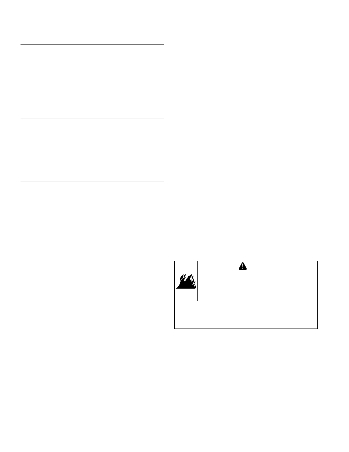
WARNING
Explosive Fuel can cause res and severe
burns.
Do not ll fuel tank while engine is hot or
running.
Gasoline is extremely ammable and its vapors can
explode if ignited. Store gasoline only in approved
containers, in well ventilated, unoccupied buildings,
away from sparks or ames. Spilled fuel could ignite
if it comes in contact with hot parts or sparks from
ignition. Never use gasoline as a cleaning agent.
NOTE: Models with a low-prole air cleaner do not have
fuel valve.
1. Stop engine.
2. Remove securing hardware and carburetor cover
panel.
3. Turn fuel valve lever to OFF position.
4. Remove fuel valve cup.
5. Clean fuel valve cup with solvent and wipe it off.
6. Check O-ring, replace if damaged. Check screen for
blockage or damage, replace if necessary. New
screen must be located on pick-up tube.
7. Place O-ring on screen followed by fuel valve cup.
Rotate fuel valve cup until it is nger tight. Turn with
a wrench 1/2 to 3/4 turn.
8. Turn fuel valve to ON position and check for leaks. If
fuel valve cup leaks repeat step 7.
9. Reinstall carburetor cover panel, using hardware
removed in step 2 to secure.
b. Use an approved fuel container to catch fuel, and
hold line below bottom of tank to observe fuel
ow.
3. Check operation of fuel shut-off valve.
a. Remove fuel sediment bowl under inlet tting of
carburetor.
b. Turn fuel shut-off valve ON and OFF and observe
operation.
Condition Conclusion
Fuel at tip of spark plug. Fuel is reaching combustion chamber.
No fuel at tip of spark plug. Check fuel ow from fuel tank (step 2).
Fuel ows from fuel line. Check operation of fuel shut-off valve (step 3).
No fuel ow from fuel line. Check fuel tank vent, in-line lter threaded into tank, and
fuel line. Correct any observed problem and reconnect
line.
Fuel ows from valve. Check for dirt and water in sediment bowl and screen.
Clean bowl and screen as needed. Check for faulty
carburetor, refer to Carburetor.
No fuel ows from valve. Check for a restriction in fuel shut-off valve or inlet elbow.
26
KohlerEngines.com 17 690 01 Rev. E
Page 27

CARBURETOR
Fuel System
WARNING
Explosive Fuel can cause res and severe
burns.
Do not ll fuel tank while engine is hot or
running.
Typical One-Barrel Carburetor Components
A
B
C
F
I
K
D
E
G
H
J
L
M
Gasoline is extremely ammable and its vapors can
explode if ignited. Store gasoline only in approved
containers, in well ventilated, unoccupied buildings, away
from sparks or ames. Spilled fuel could ignite if it comes
in contact with hot parts or sparks from ignition. Never use
gasoline as a cleaning agent.
These engines are equipped with a xed main jet
carburetor. Carburetor is designed to deliver correct fuelto-air mixture to engine under all operating conditions.
Idle mixture is set at factory and cannot be adjusted.
Troubleshooting Checklist
When engine starts hard, runs rough, or stalls at low
idle speed, check these areas before adjusting or
disassembling carburetor.
1. Make sure fuel tank is lled with clean, fresh
gasoline.
2. Make sure fuel tank cap vent is not blocked and is
operating properly.
3. Make sure fuel is reaching carburetor. This includes
checking fuel shut-off valve, fuel tank lter screen,
in-line fuel lter, fuel lines and fuel pump for
restrictions or faulty components as necessary.
4. Make sure air cleaner base and carburetor are
securely fastened to engine using gaskets in good
condition.
5. Make sure air cleaner element (including precleaner
if equipped) is clean and all air cleaner components
are fastened securely.
6. Make sure ignition system, governor system,
exhaust system, and throttle and choke controls are
operating properly.
N
O
P
A Fuel Shut-Off B Wave Washer
C Fuel Shut-Off Valve D
E Idle Jet F Fuel Shut-Off Gasket
G Main Nozzle Tube H Main Jet
I Bowl Gasket J Fuel Inlet Needle
K Spring L Hinge Pin
M Float N Fuel Bowl
Bowl Retaining Screw
O
17 690 01 Rev. E KohlerEngines.com
Gasket
P Bowl Retaining Screw
Low Idle Speed
Adjusting Screw
27
Page 28

Fuel System
Troubleshooting-Carburetor Related Causes
Condition Possible Cause Conclusion
Engine starts hard, runs rough, or
stalls at idle speed.
Engine runs rich (indicated by
black, sooty exhaust smoke,
misring, loss of speed and power,
governor hunting, or excessive
throttle opening).
Engine runs lean (indicated by
misring, loss of speed and power,
governor hunting, or excessive
throttle opening).
Fuel leaks from carburetor. Float damaged. Submerge oat to check for leaks.
Low idle fuel mixture (some models)/
speed improperly adjusted.
Clogged air cleaner. Clean or replace air cleaner.
Choke partially closed during
operation.
Dirt under fuel inlet needle. Remove needle; clean needle and seat
Bowl vent or air bleeds plugged. Clean vent, ports, and air bleeds. Blow
Leaky, cracked, or damaged oat. Submerge oat to check for leaks.
Intake air leak. Check if carburetor is loose or one of
Idle holes plugged; dirt in fuel delivery
channels.
Dirt under fuel inlet needle. Remove needle; clean needle and seat
Bowl vents plugged. Blow out with compressed air.
Carburetor bowl gasket leaks. Replace gasket.
Adjust idle speed screw or clean
carburetor.
Check choke lever/linkage to ensure
choke is operating properly.
and blow with compressed air.
out all passages with compressed air.
intake gaskets is leaking.
Clean main fuel jet and all passages;
blow out with compressed air.
Replace oat.
and blow with compressed air.
Carburetor Circuits
Float
Fuel level in bowl is maintained by oat and fuel inlet
needle. Buoyant force of oat stops fuel ow when
engine is at rest. When fuel is being consumed, oat will
drop and fuel pressure will push inlet needle away from
seat, allowing more fuel to enter bowl. When demand
ceases, buoyant force of oat will again overcome fuel
pressure, rising to predetermined setting and stop ow.
Slow and Mid-Range
At low speeds engine operates only on slow circuit. As
a metered amount of air is drawn through slow air bleed
jets, fuel is drawn through main jet and further metered
through slow jet. Air and fuel are mixed in body of slow
jet and exit to idle progression (transfer port) chamber.
From idle progression chamber, air fuel mixture is
metered through idle port passage. At low idle air/fuel
mixture is controlled by setting of idle fuel adjusting
screws. This mixture is then mixed with main body of
air and delivered to engine. As throttle plate opening
increases, greater amounts of air/fuel mixture are drawn
in through xed and metered idle progression holes.
As throttle plate opens further, vacuum signal becomes
great enough at venturi so main circuit begins to work.
Main (high-speed)
At high speeds/loads engine operates on main circuit.
As a metered amount of air is drawn through air jet,
fuel is drawn through main jet. Air and fuel are mixed
in main nozzles then enters main body of airow where
further mixing of fuel and air occurs. This mixture is then
delivered to combustion chamber. Carburetor has a xed
main circuit; no adjustment is possible.
Carburetor Adjustments
NOTE: Carburetor adjustments should be made only
after engine has warmed up.
Carburetor is designed to deliver correct fuel-to-air
mixture to engine under all operating conditions. Main
fuel jet is calibrated at factory and is not adjustable. Idle
fuel adjusting needles are also set at factory and are not
adjustable.
Low Idle Speed (RPM) Adjustment
NOTE: Actual low idle speed depends on application.
Refer to equipment manufacturer’s
recommendations. Low idle speed for basic
engines is 1800 RPM.
1. Place throttle control into idle or slow position. Turn
low idle speed adjusting screw in or out to obtain
allow idle speed of 1800 RPM (± 75 RPM).
Carburetor Servicing
WARNING
Accidental Starts can cause severe injury or
death.
Disconnect and ground spark plug lead(s)
before servicing.
Before working on engine or equipment, disable
engine as follows: 1) Disconnect spark plug lead(s). 2)
Disconnect negative (–) battery cable from battery.
28
NOTE: Main and slow jets are xed and size specic
and can be removed if required. Fixed jets for
high altitudes are available.
KohlerEngines.com 17 690 01 Rev. E
Page 29

● Inspect carburetor body for cracks, holes, and other
wear or damage.
● Inspect oat for cracks, holes, and missing or
damaged oat tabs. Check oat hinge and shaft for
wear or damage.
● Inspect fuel inlet needle and seat for wear or damage.
1. Perform removal procedures for appropriate air
cleaner and carburetor outlined in Disassembly.
2. Clean exterior surfaces of dirt or foreign material
before disassembling carburetor. Remove bowl
retaining screws, and carefully separate fuel bowl
from carburetor. Do not damage fuel bowl O-rings.
Transfer any remaining fuel into an approved
container. Save all parts. Fuel can also be drained
prior to bowl removal by loosening/removing bowl
drain screw.
3. Remove oat pin and inlet needle. Seat for inlet
needle is not serviceable and should not be
removed.
4. Clean carburetor bowl and inlet seat areas as
required.
5. Carefully remove main jet from carburetor. After
main jet is removed, main nozzles can be removed
through bottom of main towers. Note orientation/
direction of nozzles. End with 2 raised shoulders
should be out/down adjacent to main jets.
6. Save parts for cleaning and reuse unless a jet kit is
also being installed. Clean slow jets using
compressed air or carburetor cleaner, do not use
wire.
NOTE: There are 2 O-rings on body of idle jet.
Carburetor is now disassembled for appropriate cleaning
and installation of parts in overhaul kit. See instructions
provided with repair kits for more detailed information.
Fuel System
High Altitude Operation
Engines may require a high altitude carburetor kit to
ensure correct engine operation at altitudes above
1219 meters (4000 ft.). To obtain high altitude kit
information or to nd a Kohler authorized dealer visit
KohlerEngines.com or call1-800-544-2444 (U.S. and
Canada).
This engine should be operated in its original
conguration below 1219 meters (4000 ft.) as damage
may occur if high altitude carburetor kit is installed and
operated below 1219 meters (4000 ft.).
17 690 01 Rev. E KohlerEngines.com
29
Page 30

Governor System
GOVERNOR
Governor Components
A
B
A
C
F
D
E
C
A Flyweight B Regulating Pin
C Cross Shaft D Governor Lever
E Throttle Linkage F Throttle Lever
● When engine is at rest, and throttle is in fast position,
tension of governor spring holds throttle plate open.
When engine is operating, governor gear assembly is
rotating. Force applied by regulating pin against cross
shaft tends to close throttle plate. Governor spring
tension and force applied by regulating pin balance
each other during operation, to maintain engine
speed.
● When load is applied and engine speed and governor
gear speed decreases, governor spring tension moves
governor arm to open throttle plate wider. This allows
more fuel into engine, increasing engine speed. As
speed reaches governed setting, governor spring
tension and force applied by regulating pin will again
offset each other to hold a steady engine speed.
Governor Adjustments
NOTE: Make sure carburetor is mounted and secured in
place when adjustment is being made/checked.
Initial Adjustment Procedure
Make this initial adjustment whenever governor lever
is loosened or removed from cross shaft. To ensure
proper setting, make sure throttle linkage is connected to
governor lever and to carburetor throttle lever.
1. Close fuel shut-off valve.
2. Remove air cleaner outer cover. Then either
reposition fuel tank to access governor cross shaft
and lever joint, or disconnect fuel line and remove
tank from engine.
3. Loosen governor lever mounting nut.
4. CH260, CH270: Move governor lever clockwise until
it stops. Rotate governor cross shaft clockwise until
it stops.
CH395, CH440: Move governor lever
counterclockwise until it stops. Rotate governor
cross shaft counterclockwise until it stops.
5. Hold both in this position and torque governor lever
nut to 12 N·m (106 in. lb.).
Governed speed setting is determined by position of
throttle control. It can be variable or constant, depending
on engine application.
Governor is designed to hold engine speed constant
under changing load conditions. Most engines are
equipped with a centrifugal yweight mechanical
governor. Governor gear/yweight mechanism of
mechanical governor is mounted inside crankcase and is
driven off gear on camshaft.
This governor design works as follows:
● Centrifugal force acting on rotating governor gear
assembly causes yweights to move outward as
speed increases. Governor spring tension moves
them inward as speed decreases.
● As yweights move outward, they cause regulating pin
to move outward.
● Regulating pin contacts tab on cross shaft causing
shaft to rotate.
● One end of cross shaft protrudes through crankcase.
Rotating action of cross shaft is transmitted to throttle
lever of carburetor through external throttle linkage.
30
KohlerEngines.com 17 690 01 Rev. E
Page 31

Lubrication System
These engines use a splash lubrication system, supplying necessary lubrication to the crankshaft, camshaft,
connecting rod and valve train components.
Lubrication Components
A
C
C
B
A Dipstick B Oil Fill Plug C Oil Drain Plug
OIL RECOMMENDATIONS
Refer to Maintenance.
CHECK OIL LEVEL
NOTE: To prevent extensive engine wear or damage,
never run engine with oil level below or above
operating range indicator on dipstick.
Ensure engine is cool. Clean oil ll/dipstick areas of any
debris.
1. Remove dipstick; wipe oil off.
2. Reinsert dipstick into tube; rest on oil ll neck; turn
counterclockwise until cap drops down to lowest
point of thread leads; do not thread cap onto tube.
a. Remove dipstick; check oil level. Level should be
at top of indicator on dipstick.
or
b. Remove oil ll plug. Level should be up to point of
overowing ller neck.
3. If oil is low, add oil up to point of overowing ller
neck.
CHANGE OIL
Change oil while engine is warm.
1. Clean area around oil ll plug/dipstick and drain
plug.
2. Remove drain plug and oil ll plug/dipstick. Drain oil
completely.
3. Reinstall drain plug. Torque to 18 N·m (13 ft. lb.).
4. Fill crankcase with new oil, up to point of overowing
ller neck.
5. Reinstall oil ll plug/dipstick and tighten securely.
6. Dispose of used oil in accordance with local
ordinances.
OIL SENTRY
(if equipped)
™
This switch is designed to prevent engine from starting
in a low oil or no oil condition. Oil Sentry™ may not shut
down a running engine before damage occurs. In some
applications this switch may activate a warning signal.
Read your equipment manuals for more information. For
testing procedures refer to Electronic Ignition Systems
and Oil Sentry™ Tests.
4. Reinstall dipstick or oil ll plug and tighten securely.
17 690 01 Rev. E KohlerEngines.com
31
Page 32

Electrical System
SPARK PLUGS
CAUTION
Electrical Shock can cause injury.
Do not touch wires while engine is running.
Spark Plug Component and Details
A
B
C
Inspection
Inspect each spark plug as it is removed from cylinder
head. Deposits on tip are an indication of general
condition of piston rings, valves, and carburetor.
Normal and fouled plugs are shown in following photos:
Normal
Plug taken from an engine operating under normal
conditions will have light tan or gray colored deposits. If
center electrode is not worn, plug can be set to proper
gap and reused.
Worn
D
A Wire Gauge B Spark Plug
C Ground Electrode D Gap
NOTE: Do not clean spark plug in a machine using
abrasive grit. Some grit could remain in spark
plug and enter engine causing extensive wear
and damage.
Engine misre or starting problems are often caused
by a spark plug that has improper gap or is in poor
condition.
Engine is equipped with following spark plugs:
Gap 0.76 mm (0.03 in.)
Thread Size 14 mm
Reach 19.1 mm (3/4 in.)
Hex Size 15.9 mm (5/8 in.)
Refer to Maintenance for Repairs/Service Parts.
Service
Clean out spark plug recess. Remove plug and replace.
1. Check gap using wire feeler gauge. Adjust gap to
0.76 mm (0.03 in.).
2. Install plug into cylinder head.
3. Torque plug to 27 N·m (20 ft. lb.).
On a worn plug, center electrode will be rounded and
gap will be greater than specied gap. Replace a worn
spark plug immediately.
Wet Fouled
A wet plug is caused by excess fuel or oil in combustion
chamber. Excess fuel could be caused by a restricted air
cleaner, a carburetor problem, or operating engine with
too much choke. Oil in combustion chamber is usually
caused by a restricted air cleaner, a breather problem,
worn piston rings, or valve guides.
32
KohlerEngines.com 17 690 01 Rev. E
Page 33

Electrical System
Carbon Fouled
Soft, sooty, black deposits indicate incomplete
combustion caused by a restricted air cleaner, over rich
carburetion, weak ignition, or poor compression.
Overheated
Chalky, white deposits indicate very high combustion
temperatures. This condition is usually accompanied
by excessive gap erosion. Lean carburetor settings,
an intake air leak, or incorrect spark timing are normal
causes for high combustion temperatures.
BATTERY
A 12 volt battery (not furnished) with a minimum current
rating of 230 cold cranking amps/18 amp hours should
be sufcient for cranking most electric start engine
models. Actual cold cranking requirement depends on
engine size, application, and starting temperatures.
Cranking requirements increase as temperatures
decrease and battery capacity shrinks. Refer to
equipment's operating instructions for specic battery
requirements.
If battery charge is insufcient to turn over engine,
recharge battery.
Battery Maintenance
Regular maintenance is necessary to prolong battery
life.
Battery Test
To test battery, follow manufacturer's instructions.
ELECTRONIC IGNITION SYSTEM
Inductive Discharge Ignition System
H
G
C
D
A Ignition Module B Magnet
Air Gap 0.252 mm
C
E Flywheel F
G Spark Plug H Spark Plug Boot
I Spark Plug Terminal J Lamination
K Kill Terminal
These engines are equipped with a dependable
magneto breakerless ignition. In such a system,
electrical energy is generated by cutting of magnetic ux
lines generated from ignition magnet on engine ywheel
via prescribed air gap as it passes ignition module.
This energy is transferred through ignition module
laminations and is then converted in module electronics
and stored in module primary coil, as a current. Stored
energy is transferred at correct moment by triggering a
semiconductor switch inside module. Electrical break
by switch initiates energy transfer by causing collapse
of magnetic eld at coil primary. This includes a voltage
at coil primary that is amplied via transformer action at
coil secondary. Amplitude of voltage at coil secondary
is sufcient to jump gap at spark plug, igniting fuel air
mixture in gap and initiating combustion. Note that by
design, these modules only will provide proper function if
mounted in correct orientation.
This ignition system is designed to be trouble free for
life of engine. Other than periodically checking/replacing
spark plugs, no maintenance or timing adjustments
are necessary or possible. Mechanical systems do
occasionally fail or break down. Refer to Troubleshooting
to determine root of a reported problem.
Reported ignition problems are most often due to poor
connections. Before beginning test procedure, check
all external wiring. Be certain all ignition-related wires
are connected, including spark plug leads. Be certain all
terminal connections t snugly. Make sure ignition switch
is in run position.
(0.010 in.)
A
B
E
F
K
Kill Switch/Off
D
Position of Key
Switch
Ignition Module
(Enlarged View)
I
J
17 690 01 Rev. E KohlerEngines.com
33
Page 34

Electrical System
Electronic Ignition Systems and Oil Sentry™ Tests
1. Disconnect cap from spark plug and attach it to
terminal end of spark tester. Attach tester spring clip
to a good ground, not to spark plug. Turn ignition/key
switch ON and crank engine while observing ring
tip of tester.
Condition Conclusion
Tester is ring. Ignition system is good.
Install a new spark plug
and try to start engine. If it
still will not start, check
other possible causes
(fuel, compression, etc.).
Tester doesn't re. Go to step 2.
2. On electric start engines, remove starter cover
panel. Locate black/white kill lead coming from
ignition module inside blower housing. Disconnect
bullet connector where kill lead plugs into harness.
Repeat spark test (step 1).
Condition Conclusion
Spark is now present. Check for a shorted lead
in kill circuit or a faulty
switch (step 7).
Still no spark. Go to step 3.
3. Disconnect bullet connector where Oil Sentry
control module joins lead from Oil Sentry™ oat
™
switch (yellow leads). Repeat spark test again.
Condition Conclusion
Spark is now present. Control module or oat
switch is faulty. Test
control module (step 4) and
oat switch (step 5). If there
is still no spark, test
ignition module (step 6).
4. Set an ohmmeter to Rx1 scale and zero meter.
Connect black ohmmeter lead to yellow Oil Sentry
control module lead and touch red ohmmeter lead to
black wire.
Condition Conclusion
Continuity should be
indicated.
Replace Oil Sentry
control module for any
™
other results.
5. Set an ohmmeter to Rx1 scale and zero meter.
Connect one ohmmeter lead to Oil Sentry
switch lead (yellow with green sleeve) and touch
oat
™
other lead to a bare spot on crankcase (ground).
Drain oil from crankcase and repeat test.
With oil at proper level, no continuity should have
been indicated. After oil was drained, continuity
should have been indicated.
Condition Conclusion
No continuity indicated. Remove closure plate
from engine and remove
oat switch for further
testing (steps 5a and 5b).
a. If continuity was indicated with and without oil
above, check if insulation has been scraped off
oat switch lead.
Condition Conclusion
Lead wire is bare. Allowing it to short, repair
with electrical tape or
replace oat switch.
b. With oat switch removed, connect one
ohmmeter lead to oat switch lead terminal and
connect other lead to mounting bracket. Test
resistance with switch in normal position and
inverted. Repeat test 2 or 3 times in each
direction.
Condition Conclusion
Switch continuity should
If not, replace it.
be as indicated.
6. Set an ohmmeter to Rx1K or Rx10K scale and zero.
Connect one ohmmeter lead to kill lead (black/white)
terminal and connect other lead into spark plug cap.
a. Remove cap from spark plug lead and test
resistance of cap alone.
™
blower housing and remove ignition module. With
b. If resistances are other than specied, remove
kill lead and spark plug cap removed, test
resistance from small spade terminal to core of
spark plug lead wire. If resistance is not in this
range, replace module.
Resistance Chart
Ignition Module 13.5-18.0 K ohms
Cap 4-6 K ohms
Spade Terminal to Spark
9.5-12.9 K ohms
Plug Lead Wire
34
KohlerEngines.com 17 690 01 Rev. E
Page 35

Electrical System
7. Set an ohmmeter to Rx1 scale and zero meter. Test
ignition/key switch as follows.
a. Trace two black leads from on/off switch and
separate them from any connections. Connect
ohmmeter leads to switch leads, and check for
continuity in both switch positions.
Condition Conclusion
Continuity should be
indicated when and only
when switch is in OFF
position.
b. On electric start engines, trace four leads (red,
red/white, black, black/white) from key switch and
separate them from any connections. Connect
ohmmeter leads to black and black/white leads
and check for continuity in all three switch
positions. Then connect ohmmeter leads to red
and red/white leads and test again in all three
switch positions.
Condition Conclusion
Continuity should be
indicated between black
and black/white leads only
when key switch is in OFF
position. There should be
continuity between red
and red/white leads only
in start position.
BATTERY CHARGING SYSTEMS
Wiring Diagram-Retractable Starter
B
Replace switch for any
other results.
Replace switch for any
other results.
A
NOTE: Observe following guidelines to avoid damage to
electrical system and components:
● Make sure battery polarity is correct. A negative (-)
ground system is used.
● Make sure all ground connections are secure and in
good condition.
● Disconnect both battery cables before doing electrical
welding on equipment powered by engine. Also,
disconnect other electrical accessories in common
ground with engine.
● Prevent stator (AC) leads from touching or shorting
while engine is running. This could damage stator.
Most engines are equipped with a 3,4,10, or 18 amp
regulated battery charging system.
3/4/10/18 Amp Regulated Charging System
Stator
Stator is mounted on crankcase behind ywheel.
Should stator have to be replaced, follow procedures in
Disassembly.
Rectier-Regulator
NOTE: When installing rectier-regulator, push wiring
harness plug into regulator receptacle until it
locks into place.
Rectier-regulator is connected to engine with a
matching wiring harness containing a plug-in connector.
Grounded through wiring harness, rectier-regulator
is secured to equipment in a suitable location with two
mounting screws. To replace it, disconnect plug, and
remove two mounting screws.
Rectier-regulator converts AC voltage coming from
stator to DC voltage, while also monitoring and
controlling battery voltage. There are two different
rectier-regulators which are used; an 18 amp and a
10 amp assembly. Although externally similar, internal
circuits differ and two should not be interchanged.
Rectied Only (non-regulated) Systems
Some engines are equipped with a rectied only, nonregulated charging system, with output ranging from
3 amps to 4 amps. Rectier is normally connected to
engine with a matching wiring harness and secured
inside control panel. Grounding is achieved through
wiring harness. Rectier converts AC voltage coming
from stator to DC voltage only.
C
C
A Ignition Module B Spark Plug
C
E
17 690 01 Rev. E KohlerEngines.com
Optional Red
Ignition Switch
Oil Control Module
D
F
Oil Float Switch
Shut Down Switch
F
E
Optional Micro
35
Page 36

Electrical System
Wiring Diagram-3/4 Amp Charging System, Rectied Only
C
A
B
D
E
A Diode B Stator C Ignition Module D Spark Plug
E Oil Float Switch F Oil Control Module G Key Switch H Starter Motor
I Relay J Battery Fuse K 12 Volt Battery
G
F
H
J
I
K
36
KohlerEngines.com 17 690 01 Rev. E
Page 37

Electrical System
3/4/10/18 Amp Battery Charging Systems
NOTE: Zero ohmmeters on each scale to ensure accurate readings. Voltage tests should be made with engine
running at 3600 RPM - no load. Battery must be fully charged. Check specic gravity of battery. If low,
recharge or replace battery as necessary.
To test charging system for no charge to battery:
1. Separate bullet connector in white lead from rectierregulator. Connect an ammeter from female terminal
to positive (+) terminal of battery. Connect a DC
voltmeter from female terminal to negative (-)
terminal of battery. Leave other rectier-regulator
leads connected in normal manner. Run engine at
3600 RPM and read voltage on voltmeter.
If voltage is 14.0 volts or more, place a minimum
load of 5 amps (turn on lights if 60 watts or more, or
place a 2.5 ohm, 100 watt resistor across battery
terminals) on battery to reduce voltage. Observe
ammeter.
Condition Conclusion
Voltage is 14.0-15.0 volts
and charge rate increases
when load is applied.
Voltage is less than 14.0
volts or charge rate does
not increase when load is
applied.
2. Separate bullet connectors in AC (white) leads.
Connect an AC voltmeter across stator leads (female
terminals). With engine running at 3600 RPM,
measure AC output from stator.
Charging system is OK
and battery was fully
charged.
Test stator (steps 2 and
3).
To test charging system for battery continuously charging
at high rate:
1. Separate bullet connector in white lead from rectierregulator. Connect an ammeter from female terminal
to positive (+) terminal of battery. Connect a DC
voltmeter from female terminal to negative (-)
terminal of battery. Leave other rectier-regulator
leads connected in normal manner. Run engine at
3600 RPM and read voltage on voltmeter.
If voltage is 14.0 volts or more, place a minimum
load of 5 amps (turn on lights if 60 watts or more, or
place a 2.5 ohm, 100 watt resistor across battery
terminals) on battery to reduce voltage. Observe
ammeter.
Condition Conclusion
Voltage is 15.0 volts or
less.
Voltage is more than 15.0
volts.
Charging system is OK.
Battery is unable to hold a
charge; service or replace.
Faulty rectier-regulator;
replace.
Condition Conclusion
Voltage is 20.0 volts or
more.
Voltage is less than 20.0
volts.
3. With engine stopped, measure resistance from each
stator lead to ground using an ohmmeter.
Condition Conclusion
Resistance is innity
ohms (no continuity).
Resistance (or continuity)
is measured.
Stator is OK. Rectierregulator is faulty; replace.
Stator is probably faulty
and should be replaced.
Test stator further using
an ohmmeter (step 3).
Stator is OK (not shorted
to ground).
Stator leads are shorted to
ground; replace.
17 690 01 Rev. E KohlerEngines.com
37
Page 38

Electrical System
Wiring Diagram-10/18 Amp Charging System, with Rectier-Regulator
A
D
E
A Rectier-Regulator B Stator C Ignition Module D Spark Plug
E Oil Float Switch F Oil Control Module G Key Switch H Starter Motor
I Relay J Battery Fuse K 12 Volt Battery
C
B
G
F
H
J
I
K
38
KohlerEngines.com 17 690 01 Rev. E
Page 39

Starter System
NOTE: Do not crank engine continuously for more than 10 seconds. Allow a 60 second cool down period between
starting attempts. Failure to follow these guidelines can burn out starter motor.
NOTE: If engine develops sufcient speed to disengage starter but does not keep running (a false start), engine
rotation must be allowed to come to a complete stop before attempting to restart engine. If starter is engages
while ywheel is rotating, starter pinion and ywheel ring gear may clash, resulting in damage of starter.
NOTE: If starter does not crank engine, shut off starter immediately. Check condition of inline fuse and do not make
further attempts to start engine until condition is corrected.
NOTE: Do not drop starter or strike starter housing. Doing so can damage starter.
Engines in this series use inertia drive electric starters or retractable starters. Inertia drive electric starters are not
serviceable.
Troubleshooting-Starting Difculties
Condition Possible Cause Conclusion
Starter does not energize. Battery Check specic gravity of battery. If low, recharge or replace
battery as necessary.
Wiring Check fuse condition.
Clean corroded connections and tighten loose connections.
Replace wires in poor condition and with frayed or broken
insulation.
Starter energizes but turns
slowly.
Starter Switch
or Solenoid
Battery Check specic gravity of battery. If low, recharge or replace
Wiring Check for corroded connections, poor ground connection.
Transmission
or
Engine
Check switch or relay operation. If starter cranks normally,
replace faulty components.
battery as necessary.
Make sure clutch or transmission is disengaged or placed
in neutral. This is especially important on equipment with
hydrostatic drive. Transmission must be exactly in neutral to
prevent resistance which could keep engine from starting.
Check for seized engine components such as bearings,
connecting rod, and piston.
Electric Starting System Tests
1. Test battery on unit.
a. Connect a DC voltmeter across battery terminals
and read battery voltage (key switch OFF).
b. Turn key switch to start position and read battery
voltage again. Turn switch OFF.
Condition Conclusion
Voltage less than 12 volts. Charge battery.
Battery voltage should not
fall below 9 volts during
cranking.
If it does, battery may be
faulty or there may be a
short in starting circuit.
Have battery load tested.
If battery passes load test,
check circuitry.
2. Remove electric starter cover panel and check fuse
inside plastic holder. Fuse outside holder is a spare.
Condition Conclusion
Fuse is blown. Check for a wiring
problem (bare wire, short
circuit). Correct problem
and replace fuse. Try to
start engine. If it still won’t
start, go to step 3.
3. Disconnect blue relay lead. Be sure transmission is
in neutral and PTO is OFF. Connect one end of a
jumper lead to positive terminal of battery. Connect
other end to terminal of relay.
Condition Conclusion
Relay engages and starter
begins to crank.
Key switch is faulty, or
there is a wiring problem
to/from key switch. Check
wiring and test key switch
circuits with an ohmmeter.
17 690 01 Rev. E KohlerEngines.com
39
Page 40

Starter System
4. Use a known, good, fully-charged battery and
jumper cables to test starter motor. Be sure
transmission is in neutral and PTO is OFF.
Remove heavy lead from post terminal on starter.
Connect one end of positive jumper cable to post
terminal and connect other end to positive terminal
of battery.
Connect one end of negative jumper cable to
negative terminal of battery. Touch other end of
negative jumper cable to a bare surface on
crankcase or to starter housing.
Condition Conclusion
Relay engages and starter
begins to crank.
5. Disconnect leads from starter relay and remove it
from starter for testing.
a. Set an ohmmeter on Rx1 scale and zero meter.
Connect one ohmmeter lead to terminal of blue
lead from relay. Connect other ohmmeter lead to
relay mounting bracket.
Key switch is faulty, or
there is a wiring problem
to/from key switch. Check
wiring and test key switch
circuits with an ohmmeter.
Condition Conclusion
Meter reading less than
3.4 ohms, or an open
circuit is indicated (innity
ohms).
b. With ohmmeter still on Rx1 scale, connect leads
to two large post terminals. Meter should indicate
an open circuit (innity ohms, no continuity).
c. Leave ohmmeter leads connected to large
terminals. Connect a jumper lead from positive
terminal of battery to terminal of blue relay lead.
Connect another jumper lead from negative
terminal of battery to relay mounting bracket.
Condition Conclusion
When circuit is completed,
applying 12 volts to
energizing coil, an audible
click should be heard as
relay engages, and
ohmmeter should then
indicate continuity
between large terminals.
Relay is faulty and must
be replaced.
Results are other than
indicated, replace relay.
40
KohlerEngines.com 17 690 01 Rev. E
Page 41

RETRACTABLE STARTERS
WARNING
Uncoiling Spring can cause severe injury.
Wear safety goggles or face protection when
servicing retractable starter.
Retractable Starter Components
Starter System
Retractable starters contain a powerful, recoil spring that is
under tension. Always wear safety goggles when servicing
retractable starters and carefully follow instructions in
"Retractable Starter" for relieving spring tension.
A
J
B
C
D
E
F
G
H
I
CH270 CH395
A Center Screw B Drive Plate C Friction Spring D Drive Pawl (Dogs)
E Drive Pawl Springs F Pulley G Recoil Spring H Starter Rope
I Starter Handle J Double Left-Hand Knot
H
17 690 01 Rev. E KohlerEngines.com
41
Page 42

Starter System
Remove Starter
1. Remove screws securing starter to blower housing.
2. Remove starter assembly.
Rope Replacement
NOTE: Do not allow pulley/spring to unwind. Enlist aid
of a helper if necessary.
Rope can be replaced without complete starter
disassembly.
1. Remove starter assembly from engine.
2. Pull rope out approximately 12 in. and tie a
temporary (slip) knot in it to keep it from retracting
into starter.
3. Pull knot end out of handle, untie knot, and slide
handle off.
4. Hold pulley rmly and untie slipknot. Allow pulley to
rotate slowly as spring tension is released.
5. When all spring tension on starter pulley is released,
remove rope from pulley.
6. Tie a double left-hand knot in one end of new rope.
7. Rotate pulley counterclockwise to pre-tension spring
(approximately 4 full turns of pulley).
8. Continue rotating pulley counterclockwise until rope
hole in pulley is aligned with rope guide bushing of
starter housing.
9. Insert unknotted end of new rope through rope hole
in starter pulley and rope guide bushing of housing.
10. Tie a slipknot approximately 12 in. from free end of
rope. Hold pulley rmly and allow it to rotate slowly
until slipknot reaches guide bushing of housing.
11. Insert starter rope through starter handle and tie a
double, left-hand knot at end of starter rope. Insert
knot into hole in handle.
12. Untie slip knot and pull on starter handle until starter
rope is fully extended. Slowly retract starter rope into
starter assembly. If recoil spring is properly
tensioned, starter rope will retract fully and starter
handle will stop against starter housing.
Pawls (dogs) Replacement
1. Install a clamp to hold pulley in starter housing and
prevent it from rotating.
2. Unscrew center screw and lift off drive plate.
3. Note positions of pawls and pawl springs before
removing. Remove parts from pulley.
4. Install pawl springs and pawls into pawl slots of
pulley. All parts must by dry.
5. Position drive plate over pawls, aligning actuating
slots in place with raised sections on each drive
pawl. Torque center screw to 5-6 N·m (44-54 in. lb.).
6. Remove clamp and pull starter rope out part way to
check operation of pawls.
Install Starter
1. Install retractable starter onto blower housing leaving
screws slightly loose.
2. Pull starter handle out until pawls engage in drive
cup. Hold handle in this position and tighten screws
securely.
42
KohlerEngines.com 17 690 01 Rev. E
Page 43

WARNING
Accidental Starts can cause severe injury or
death.
Disconnect and ground spark plug lead(s)
before servicing.
External Engine Components
Disassembly/Inspection and Service
Before working on engine or equipment, disable engine as
follows: 1) Disconnect spark plug lead(s). 2) Disconnect
negative (–) battery cable from battery.
H
D
J
I
E
F
G
B
C
K
A
A Oil Drain Plug B
E
Quad-Clean
Element/Precleaner
™
I Fuel Line J
F Quad-Clean™ Base G Carburetor Shroud H Fuel Tank
CH395, CH440
Mufer Assembly
CH260, CH270
Mufer Assembly
C Breather Hose D Quad-Clean™ Cover
K
17 690 01 Rev. E KohlerEngines.com
Low-Prole Air
Cleaner
43
Page 44

Disassembly/Inspection and Service
Clean all parts thoroughly as engine is disassembled.
Only clean parts can be accurately inspected
and gauged for wear or damage. There are many
commercially available cleaners that will quickly remove
grease, oil, and grime from engine parts. When such a
cleaner is used, follow manufacturer’s instructions and
safety precautions carefully.
Make sure all traces of cleaner are removed before
engine is reassembled and placed into operation. Even
small amounts of these cleaners can quickly break down
lubricating properties of engine oil.
Disconnect Spark Plug Lead
Fuel Valve Details
A
B
A Fuel Shut-Off Valve B Turn to Off Position
NOTE: Pull on boot only, to prevent damage to spark
plug lead.
NOTE: Models with low-prole air cleaner do not have
fuel shut-off valve. Instead, turn off fuel at fuel
supply.
1. Disconnect lead from spark plug.
2. Push fuel shut-off lever left to close fuel valve.
Drain Oil From Crankcase
1. Remove 1 oil drain plug and 1 oil ll plug.
2. Allow ample time for oil to drain from crankcase.
Remove Air Cleaner Assembly
Remove air cleaner components from air cleaner base.
Refer to Air Cleaner/Intake.
Remove Quad-Clean™ Base
Remove air cleaner base from engine as follows:
1. Remove nuts and screws securing carburetor
shroud to engine.
2. Remove shroud.
3. Remove screw and nuts securing air cleaner base to
carburetor.
4. Disconnect one end of breather hose from valve
cover or air cleaner base.
5. Pull air cleaner base off studs.
6. Remove air cleaner base gasket from mounting
studs.
7. Loosely install nuts on studs (to temporarily hold
carburetor on engine).
Remove Low-Prole Air Cleaner Base
Remove air cleaner base from engine as follows:
1. Remove screw and nuts securing air cleaner base to
carburetor.
2. Disconnect one end of breather hose from valve
cover or air cleaner base.
3. Remove base.
4. Remove air cleaner base gasket from mounting
studs.
5. Loosely install nuts on studs (to temporarily hold
carburetor on engine).
Remove Fuel Tank (if equipped)
NOTE: If no fuel tank is equipped, loosen clamp and
disconnect fuel line from inlet of carburetor.
1. Ensure fuel tank is empty.
2. Loosen clamp and disconnect fuel line from inlet of
shut-off valve.
3. Remove screws and nuts securing fuel tank to
engine brackets and remove tank from engine.
Remove Mufer and Heat Shield Assembly
1. Remove screws from exhaust ange and mufer
bracket.
2. Remove mufer assembly from exhaust outlet.
3. Remove exhaust gasket from outlet.
44
KohlerEngines.com 17 690 01 Rev. E
Page 45

CH260/CH270 Blower Housing/Control Panel Components
Disassembly/Inspection and Service
F
E
D
C
B
G
H
J
I
K
A
A Retractable Starter B Blower Housing C Lower Shield D Carburetor
E Dampening Spring F Throttle Linkage G Governor Lever H Hex Flange Nut
I Governor Spring J Throttle Lever K Upper Shield
17 690 01 Rev. E KohlerEngines.com
45
Page 46

Disassembly/Inspection and Service
CH395/CH440 Blower Housing/Control Panel Components
M
L
K
F
G
E
J
I
H
N
G
D
B
C
A
A Retractable Starter B Blower Housing C Lower Shield D Electric Starter
E Upper Shield F Carburetor G Fuel Brackets H Throttle Lever
I Pivot Lever J Governor Spring K Dampening Spring L Throttle Linkage
M Governor Lever N Hex Flange Nut
46
KohlerEngines.com 17 690 01 Rev. E
Page 47

Disassembly/Inspection and Service
Remove External Throttle, Governor and Choke
Linkage
1. Mark which hole location governor spring is in on
each side. Remove nut and washer securing throttle
control lever to crankcase. Unhook spring and
remove lever.
2. Loosen nut securing governor lever to governor
shaft. Lift off governor lever and remove carburetor
throttle link and dampening spring.
Remove Carburetor
WARNING
Explosive Fuel can cause res and severe
burns.
Do not ll fuel tank while engine is hot or
running.
Gasoline is extremely ammable and its vapors can
explode if ignited. Store gasoline only in approved
containers, in well ventilated, unoccupied buildings,
away from sparks or ames. Spilled fuel could ignite
if it comes in contact with hot parts or sparks from
ignition. Never use gasoline as a cleaning agent.
NOTE: To remove carburetor without disturbing
governor lever mounting, pull carburetor outward
and off mounting studs. Tilt carburetor and
disconnect throttle link and dampening spring
from throttle lever.
Disconnect throttle link and dampening spring from
carburetor. Remove carburetor, carburetor gasket,
insulator, and insulator gasket from studs.
Remove Retractable Starter
Remove screws securing retractable starter to blower
housing. Remove starter.
Remove Blower Housing and Shields
1. Remove screws and nuts (CH260 and CH270 only)
securing blower housing.
2. Remove blower housing.
3. Remove screws securing upper shield and remove
shield.
4. Remove screws securing lower shield and remove
shield.
Remove Electrical Wiring, Micro Shut Down Switch
and Bracket and Fuel Tank Brackets
NOTE: For CH395 and CH440 it is not required and not
recommended to remove threaded stud and
micro switch bracket.
1. Disconnect wiring harness bullet connectors for Oil
Sentry
screw securing module to fuel tank bracket.
oat switch and module. Remove mounting
™
2. Remove both fuel tank brackets by removing screws
in each. Remove threaded stud from left bracket and
remove micro switch bracket.
Cylinder Head Components
J
L
M
I
H
G
N
K
D
C
A
B
F
E
A Valve Cover B Adjuster Nut C Rocker Arm D Rocker Arm Stud
E Push Rod Guide F Push Rod G Valve Keeper H Valve Spring
I Valve Stem Seal J Spark Plug K Cylinder Head L Valve
M Dowel Pin N
Cylinder Head
Gasket
17 690 01 Rev. E KohlerEngines.com
47
Page 48

Disassembly/Inspection and Service
Remove Control Panel and Electric Starter (if
equipped)
NOTE: To ease reassembly, label wires for proper
reconnection as wiring colors may not match.
1. Disconnect wires from control panel to starter, Oil
Sentry
, ignition module, and rectier-regulator.
™
2. Remove screws securing control panel bracket to
crankcase, and remove control panel. Note 2 ground
wires secured by one screw.
3. Remove screws securing electric starter to
crankcase, and remove electric starter.
Remove Valve Cover/Breather, Rocker Arms, Push
Rods, and Cylinder Head Assembly
NOTE: Mark location of push rods and any other part
removed being reused.
1. Remove screw and washer and remove valve cover
and gasket from engine. Breather assembly is inside
valve cover.
2. Loosen and remove rocker arm lock and adjuster
nuts. Remove rocker arms and push rods.
3. Remove spark plug.
4. Remove screws securing cylinder head.
5. Remove cylinder head, dowel pins, and cylinder
head gasket.
Breather System
Breather system is designed to control amount of oil
in head area and still maintain necessary vacuum in
crankcase.
When pistons move downward, crankcase gases are
pushed past reed through mesh lter into intake system.
Upward travel of pistons closes reed and creates a
low vacuum in lower crankcase. Any oil separated out
through lter drains back into crankcase.
Remove Valves
NOTE: Mark locations of any part removed being
reused.
1. Supporting head of valve from below, depress valve
keeper and valve spring until keeper can be
released from valve stem. Remove valve spring and
valve from head. Repeat this procedure for
remaining valve.
2. Remove and replace valve stem seals whenever
cylinder head is serviced or disassembled.
Inspection and Service
After cleaning, check atness of cylinder head and
corresponding top surface of crankcase, using a surface
plate or piece of glass and feeler gauge. Maximum
allowable out of atness is 0.1 mm (0.0039 in.).
Carefully inspect valve mechanism parts. Inspect valve
springs and related hardware for excessive wear or
distortion. Check valves and valve seat area or inserts
for evidence of deep pitting, cracks, or distortion. Check
clearance of valve stems in guides.
Hard starting, or loss of power accompanied by high
fuel consumption may be symptoms of faulty valves.
Although these symptoms could also be attributed to
worn rings, remove and check valves rst. After removal,
clean valve heads, faces, and stems with a power wire
brush.
Then, carefully inspect each valve for defects such as
warped head, excessive corrosion, or worn stem end.
Replace valves found to be in bad condition.
Valve Guides
If a valve guide is worn beyond specications, it will not
guide valve in a straight line. This may result in burnt
valve faces or seats, loss of compression, and excessive
oil consumption.
To check valve guide-to-valve stem clearance,
thoroughly clean valve guide and, using a split-ball
gauge, measure inside diameter of guide. Then, using
an outside micrometer, measure diameter of valve stem
at several points on stem where it moves in valve guide.
Use largest stem diameter to calculate clearance by
subtracting stem diameter from guide diameter. If intake
or exhaust clearance exceeds specications in Valve
Specication table, determine whether valve stem or
guide is responsible for excessive clearance.
If guides are within limits but valve stems are worn
beyond limits, install new valves.
Valve Seat Inserts
Hardened steel alloy intake and exhaust valve seat
inserts are press-tted into cylinder head. Inserts are
not replaceable but can be reconditioned if not too badly
pitted or distorted. If cracked or badly warped, cylinder
head should be replaced.
Recondition valve seat inserts following instructions
provided with valve seat cutter being used. Cutting
proper valve face angle, as specied in Valve
Specication table and proper valve seat angle (89.5°90°) will achieve desired 0° (1° full cut) interference
angle where maximum pressure occurs on outside
diameters of valve face and seat.
Lapping Valves
Reground or new valves must be lapped in, to provide
proper t. Use a hand valve grinder with suction cup
for nal lapping. Lightly coat valve face with ne grade
of grinding compound, then rotate valve on seat with
grinder. Continue grinding until smooth surface is
obtained on seat and on valve face. Thoroughly clean
cylinder head in soap and hot water to remove all traces
of grinding compound. After drying cylinder head, apply
a light coating of SAE 10 oil to prevent rusting.
Valve Stem Seals
These engines use valve stem seals on intake and
exhaust valves.
Always use new seals when valves are removed
from cylinder head. Seals should also be replaced if
deteriorated or damaged in any way. Never reuse old
seals.
48
KohlerEngines.com 17 690 01 Rev. E
Page 49

Disassembly/Inspection and Service
Valve Details
D
C
A
E
Item Dimension Intake Exhaust
A Head Diameter 26.875-27.125 mm
B Valve Length 63.3-63.9 mm (2.4921-2.5157) 63.3-63.9 mm (2.4921-2.5157)
C Stem Diameter 5.5 mm (0.217 in.) 5.438 mm (0.214 in.)
D Face/Seat Width - Maximum 2.0 mm (0.079 in.) 2.0 mm (0.079 in.)
E Face/Seat Angle 89.5°-90.5° 89.5°-90.5°
B
C
CH260/CH270 Valve Specications
D
(1.0581-1.0679 in.)
24.875-25.125 mm
(0.9793-0.9892 in.)
CH395 Valve Specications
Item Dimension Intake Exhaust
A Head Diameter 30.875-31.125 mm
(1.2156-1.2254 in.)
B Valve Length 85.34-85.54 mm
(3.3598-3.3677 in.)
C Stem Diameter 6.560-6.575 mm
(0.2583-0.2589 in.)
D Face/Seat Width - Maximum 1.5 mm (0.059 in.) 1.5 mm (0.059 in.)
E Face/Seat Angle 89.5°-90.5° 89.5°-90.5°
CH440 Valve Specications
Item Dimension Intake Exhaust
A Head Diameter 35.875-36.125 mm
(1.4124-1.4222 in.)
B Valve Length 86.175-86.375 mm
(3.3927-3.4006 in.)
C Stem Diameter 6.560-6.575 mm
(0.2583-0.2589 in.)
D Face/Seat Width - Maximum 1.5 mm (0.059 in.) 1.5 mm (0.059 in.)
E Face/Seat Angle 89.5°-90.5° 89.5°-90.5°
26.875-27.125 mm
(1.0581-1.0679 in.)
85.19-84.99 mm
(3.3461-3.3539 in.)
6.560-6.575 mm
(0.2583-0.2589 in.)
32.875-33.125 mm
(1.2943-1.3041 in.)
86.341-86.541 mm
(3.3993-3.4071 in.)
6.545-6.560 mm
(0.2577-0.2583 in.)
17 690 01 Rev. E KohlerEngines.com
49
Page 50

Disassembly/Inspection and Service
CH260/CH270 Flywheel/Ignition Components
E
C
B
A
Flywheel Retaining
A
C Flywheel Fan D Ignition Module
E Flywheel F Stator
G Flywheel Shield
CH395/CH440 Flywheel/Ignition Components
B
A
Nut
D
C
E
D
F
G
B Drive Cup
G
F
Remove Ignition Module
Remove screws securing ignition module to crankcase.
Remove module.
Remove Flywheel
NOTE: Whenever possible, an impact wrench should be
used to loosen ywheel retaining nut. A ywheel
strap wrench may be used to hold ywheel when
loosening or tightening ywheel retaining nut.
NOTE: Always use a puller to remove ywheel from
crankshaft. Do not strike ywheel or crankshaft
as these parts could become cracked or
damaged.
1. Remove ywheel retaining nut.
2. Remove drive cup and fan from ywheel.
3. Remove screw and shield (CH260 and CH270 only)
on right side of ywheel (required for use of puller in
next step).
4. Remove ywheel from crankshaft using a suitable
puller.
5. Remove ywheel key from crankshaft keyway.
Inspection
Inspect ywheel for cracks and ywheel keyway for
damage. Replace ywheel if it is cracked. Replace
ywheel, crankshaft, and key if ywheel key is sheared
or keyway is damaged.
Remove Stator (if equipped)
1. Remove screw securing stator wire bracket and
remove bracket.
2. Remove screws securing stator to crankcase.
Flywheel Retaining
A
C Flywheel Fan D Ignition Module
E Flywheel F Stator
G Flywheel Shield
Nut
B Drive Cup
50
KohlerEngines.com 17 690 01 Rev. E
Page 51

Disassembly/Inspection and Service
CH260/CH270 Crankshaft/Camshaft/Closure Plate Components
M
L
U
V
R
O
S
N
Q
T
P
I
J
E
H
C
G
F
D
A
K
B
A Closure Plate Oil Seal B Closure Plate C Closure Plate Bearing D Camshaft
E Crankshaft F Piston Pin Retainer G Piston Pin H Piston
I
M Governor Washer N Governor Shaft O Governor Gear P
Q Tappet R Oil Sentry
Connecting Rod
End Cap
J Connecting Rod K Piston Ring Set L Governor Cup
Oil Sentry
Wire S Crankcase Bearing T Crankcase
™
™
Switch
U Governor Cross Shaft V Crankcase Oil Seal
Float
17 690 01 Rev. E KohlerEngines.com
51
Page 52

Disassembly/Inspection and Service
CH395/CH440 Crankshaft/Camshaft/Closure Plate Components
X
V
U
Y
S
T
W
R
Q
H
I
G
F
E
D
C
J
M
K
O
N
L
P
A
B
A Closure Plate Oil Seal B Closure Plate C Closure Plate Bearing D
Closure Plate Balance
Shaft Bearing
E Balance Shaft F Governor Shaft G Governor Washer H Governor Gear
I Governor Cup J Crankshaft K
Connector Rod
End Cap
L Connector Rod
M Piston Pin Retainer N Piston Pin O Piston P Piston Ring Set
Q Camshaft R
Crankcase Balance
U
Shaft Bearing
Oil Sentry
V Crankcase Bearing W Crankcase X Governor Cross Shaft
™
Switch
Float
S Oil Sentry™ Wire T Tappet
Y Crankcase Oil Seal
52
KohlerEngines.com 17 690 01 Rev. E
Page 53

Disassembly/Inspection and Service
Remove Closure Plate
NOTE: Do not pry on gasket surface of crankcase or
closure plate, as this can cause damage and
leakage.
1. Remove screws securing closure plate to crankcase.
2. Remove closure plate, gasket, and dowel pins (if
required) from crankcase.
3. Remove shims from crankshaft and camshaft.
Inspection
Inspect main bearing surface for wear or damage (refer
to Specications). Replace closure plate if required.
Remove Balance Shaft (if equipped)
Remove balance shaft by pulling it straight out of
crankcase.
Remove Camshaft and Valve Tappets
1. Remove camshaft by pulling it straight out of
crankcase.
2. Remove valve tappets by pulling them straight out of
crankcase. Mark their positions.
Automatic Compression Release (ACR)
ACR Operation Details
Benets
As a result of reduced compression at cranking speeds,
several important benets are obtained:
1. Manual (retractable) starting is much easier. Without
ACR, manual starting would be virtually impossible.
2. Electric start models can use a smaller starter and
battery more practical for application.
3. ACR eliminates need for a spark retard/advance
mechanism. A spark retard/advance mechanism
would be required on engines without ACR to
prevent kickback which would occur during starting.
ACR eliminates this kickback making manual
starting safer.
4. Choke control setting is less critical with ACR. In
event of ooding, excess fuel is blown out opened
exhaust valve and does not hamper starting.
5. Engines with ACR start much faster in cold weather
than engines without ACR.
6. Engines with ACR can be started with worn or fouled
spark plugs. Engines without ACR are more difcult
to start with those same spark plugs.
Inspection and Service
Dimension A
A
C
B
A
A Camshaft B Exhaust Cam Lobe
C
E Arm
ACR mechanism consists of a spring-loaded arm and
sliding pin mounted to camshaft. When engine is rotating
at low cranking speeds, arm holds pin so it protrudes
above heel of exhaust cam. This holds exhaust valve off
of its seat during rst part of compression stroke.
After engine speed increases centrifugal force causes
spring-loaded arm to move outward causing pin to
retract. When in this position pin has no effect on
exhaust valve and engine operates at full compression
and power.
Decompression
Weight
E
D
D Return Spring
CH260/CH270 Cam Lobe
Valve Dimension A Service Limit
INTAKE
EXHAUST
CH395 Cam Lobe
INTAKE
EXHAUST
CH440 Cam Lobe
INTAKE
EXHAUST
28.263 mm
(1.1127 in.)
28.346 mm
(1.1160 in.)
32.544 mm
(1.2813 in.)
32.256 mm
(1.2699 in.)
32.266 mm
(1.3097 in.)
32.260 mm
(1.2701 in.)
27.585 mm
(1.0860 in.)
27.666 mm
(1.0892 in.)
32.110 mm
(1.2642 in.)
31.790 mm
(1.2516 in.)
32.642 mm
(1.2851 in.)
31.610 mm
(1.2445 in.)
17 690 01 Rev. E KohlerEngines.com
53
Page 54

Disassembly/Inspection and Service
Dimension B
B
Cam Lobe Specications
Engine
Model
CH260,
CH270
CH395
CH440
Dimension C
Camshaft Journal Specications
Engine Model Dimension Limit
CH260, CH270
CH395, CH440
Inspect gear teeth of camshaft. If teeth are badly
worn, chipped, or some are missing, replacement of
camshaft will be necessary. If unusual wear or damage
is evident on either lobe or mating tappet, camshaft and
both tappets must be replaced. Check condition and
operation of ACR mechanism.
Valve Dimension B Service Limit
INTAKE
EXHAUST
INTAKE
EXHAUST
INTAKE
EXHAUST
22.200 mm
(0.8740 in.)
22.200 mm
(0.8740 in.)
26.060 mm
(1.0260 in.)
26.060 mm
(1.0260 in.)
26.092 mm
(1.0272 in.)
26.000 mm
(1.0236 in.)
13.975 mm
(0.5500 in.)
15.975 mm
(0.6289 in.)
21.582 mm
(0.8497 in.)
21.582 mm
(0.8497 in.)
25.440 mm
(1.0044 in.)
25.440 mm
(1.0044 in.)
25.041 mm
(0.9859 in.)
24.970 mm
(0.9831 in.)
C
13.900 mm
(0.5470 in.)
15.900 mm
(0.6260 in.)
Measure cam lobe prole, A and B, using an outside
micrometer and compare with specications listed.
Measure the camshaft journals, C, which t in the ball
bearings, for wear using a micrometer. Compare with
specications listed.
Remove Piston, Connecting Rod and Crankshaft
NOTE: If a carbon ridge is present at top of cylinder
bore, use a ridge reamer to remove it before
attempting to remove piston.
1. Remove screws securing end cap to connecting rod.
Remove end cap. Carefully guiding connecting rod,
slide piston and connecting rod from cylinder bore.
2. Remove crankshaft from crankcase.
Connecting Rods Inspection and Service
Check bearing area (big end) for excessive wear, score
marks, running and side clearances (see Specications
and Tolerances). Replace rod and cap if scored or
excessively worn.
Service replacement connecting rods are available
in STD size and 0.25 mm (0.010 in.) undersize. 0.25
mm (0.010 in.) undersized rods have an identication
marking on lower end of rod shank. Always refer
to appropriate parts information to ensure correct
replacements are used.
Piston and Rings Inspection
Scufng and scoring of pistons and cylinder walls occurs
when internal engine temperatures approach welding
point of piston. Temperatures high enough to do this are
created by friction, which is usually attributed to improper
lubrication and/or overheating of engine.
Normally, very little wear takes place in piston bosspiston pin area. If original piston and connecting rod can
be reused after new rings are installed, original pin can
also be reused but new piston pin retainers are required.
Piston pin is included as part of piston assembly – if pin
boss in piston or pin are worn or damaged, a new piston
assembly is required.
Ring failure is usually indicated by excessive oil
consumption and blue exhaust smoke. When rings fail,
oil is allowed to enter combustion chamber where it is
burned along with fuel. High oil consumption can also
occur when piston ring end gap is incorrect because
ring cannot properly conform to cylinder wall under this
condition. Oil control is also lost when ring gaps are not
staggered during installation.
When cylinder temperatures get too high, lacquer and
varnish collect on pistons causing rings to stick, which
results in rapid wear. A worn ring usually takes on a
shiny or bright appearance.
Scratches on rings and pistons are caused by abrasive
material such as carbon, dirt, or pieces of hard metal.
Detonation damage occurs when a portion of fuel charge
ignites spontaneously from heat and pressure shortly
after ignition. This creates 2 ame fronts, which meet
and explode to create extreme hammering pressures on
a specic area of piston. Detonation generally occurs
from using low octane fuels.
Preignition, or ignition of fuel charge before timed spark
can cause damage similar to detonation. Preignition
damage is often more severe than detonation damage.
54
KohlerEngines.com 17 690 01 Rev. E
Page 55

Disassembly/Inspection and Service
Preignition is caused by a hot spot in combustion
chamber such as glowing carbon deposits, blocked
cooling ns, an improperly seated valve, or wrong spark
plug(s).
Replacement pistons are available in STD bore size,
and 0.25 mm (0.010 in.) oversize. Replacement pistons
include new piston ring sets and new piston pins.
Replacement ring sets are also available separately for
STD, and 0.25 mm (0.010 in.) oversize pistons. Always
use new piston rings when installing pistons. Never use
old rings.
Some important points to remember when servicing
piston rings:
1. Cylinder bore must be deglazed before service ring
sets are used.
2. If cylinder bore does not need reboring and if old
piston is within wear limits and free of score or scuff
marks, old piston may be reused.
3. Remove old rings and clean up grooves. Never
reuse old rings.
4. Before installing new rings on piston, place top 2
rings, each in turn, in its running area in cylinder
bore and check end gap. Refer to Specications.
5. After installing new compression (top and middle)
rings on piston, check piston-to-ring side clearance.
Refer to Specications. If side clearance is greater
than specied, a new piston must be used.
Install New Piston Rings
A
B
D
E
F
A Top Compression
Ring
C Oil Control Ring D Top Rail
E Expander Ring F Bottom Rail
C
B Middle Compression
Ring
Piston Ring Orientation
C
B
A
A 2nd Ring Gap B Bottom Oil Rail Gap
C Oil Ring Expander
Gap
E Top Ring Gap
NOTE: Rings must be installed correctly. Install bottom
(oil control) ring rst and top compression ring
last.
Use a piston ring expander to install rings.
1. Oil control ring (bottom groove): Install expander and
then rails. Make sure ends of expander are not
overlapped.
2. Middle compression ring (center groove): Install
center ring using a piston ring expander tool. Make
sure identication mark is up or colored dye stripe (if
contained) is left of end gap.
3. Top compression ring (top groove): Install top ring
using a piston ring expander tool. Make sure
identication mark is up or colored dye stripe (if
contained) is to left of end gap.
Crankshaft Inspection and Service
Inspect gear teeth of crankshaft. If teeth are badly worn,
chipped, or some are missing, replacement of crankshaft
will be necessary.
Inspect crankshaft bearing surfaces for scoring,
grooving, etc. Measure running clearance between
crankshaft journals and their respective bearing bores.
Use an inside micrometer or telescoping gauge to
measure inside diameter of both bearing bores in vertical
and horizontal planes. Use an outside micrometer to
measure outside diameter of crankshaft main bearing
journals. Subtract journal diameters from their respective
bore diameters to get running clearances. Check results
against values in Specications and Tolerances. If
running clearances are within specication, and there
is no evidence of scoring, grooving, etc., no further
reconditioning is necessary. If bearing surfaces are worn
or damaged, crankcase and/or closure plate will need to
be replaced.
D Top Oil Rail Gap
D
E
17 690 01 Rev. E KohlerEngines.com
55
Page 56

Disassembly/Inspection and Service
Inspect crankshaft keyways. If worn or chipped,
replacement of crankshaft will be necessary. Inspect
crankpin for score marks or metallic pickup. Slight score
marks can be cleaned with crocus cloth soaked in oil. If
wear limits are exceeded, as stated in Specications, it
will be necessary to replace crankshaft.
Remove Oil Sentry™ System
1. Remove nut securing Oil Sentry
assembly in crankcase.
lead wire grommet
™
2. Pull grommet assembly from inside of crankcase.
3. Remove screws securing Oil Sentry
crankcase. Remove oat switch assembly.
oat switch to
™
Remove Governor Assembly
CH260, CH270
NOTE: Mark orientation of all parts as governor
assembly is removed.
1. Remove cup and washer from governor gear.
2. Using a suitable drift, drive governor gear shaft from
crankcase.
3. Remove hitch pin and washer from governor cross
shaft.
4. Remove cross shaft from inside crankcase.
CH395
NOTE: Governor gear shaft is pressed into closure
plate, and should not be removed.
NOTE: Take note of orientation of governor gear
components.
1. Governor gear is located in closure plate. To remove
governor gear, pull governor gear off shaft.
2. Remove hitch pin and washer from governor cross
shaft.
3. Remove cross shaft from inside crankcase.
CH440
NOTE: Do not pry on gasket surface of closure plate, as
this can cause damage and leakage.
NOTE: Take note of orientation of governor gear
components.
NOTE: Governor gear shaft is pressed into closure
plate, and should not be removed unless
damaged.
1. Governor gear is located in closure plate. To remove
governor gear, pry underneath gear to lift it off shaft.
2. If governor gear shaft is bent or damaged, remove it
by pulling straight out.
3. Remove hitch pin and washer from governor cross
shaft.
4. Remove cross shaft from inside crankcase.
Inspection
Inspect governor gear teeth. Replace gear if it is worn,
chipped, or if any teeth are missing. Inspect governor
weights. They should move freely in governor gear.
Remove Crankcase and Closure Plate Seals and
Bearings
NOTE: Inspect bearings for signs of wear by rotating
inner race and examine for marring or cracks.
Check to make sure race moves easily and is
not sloppy. If bearing is tight and rotates
smoothly, removal is not necessary. If you feel
any roughness or chattering or bearing is sloppy,
it should be replaced.
1. Remove oil seal from crankcase.
2. Using a suitable press, push crankshaft bearing from
crankcase.
3. Remove oil seal from closure plate.
4. Using a suitable press, push crankshaft bearing from
closure plate.
Crankcase Inspection and Service
Cylinder Bore Detail
NOTE: A 0.25 mm (0.010 in.) oversize piston is
available if resizing is selected. Initially, resize
using a boring bar, then follow procedures for
honing cylinder.
Check all gasket surfaces to make sure they are free of
gasket fragments. Gasket surfaces must also be free of
deep scratches or nicks.
Check cylinder bore for scoring. In severe cases,
unburned fuel can cause scufng and scoring of cylinder
wall. It washes necessary lubricating oils off piston and
cylinder wall. As raw fuel seeps down cylinder wall,
piston rings make metal to metal contact with wall.
Scoring of cylinder wall can also be caused by localized
hot spots resulting from blocked cooling ns or from
inadequate or contaminated lubrication.
If cylinder bore is badly scored, excessively worn,
tapered, or out-of-round, resizing is necessary. Use an
inside micrometer to determine amount of wear (refer to
Specications).
56
KohlerEngines.com 17 690 01 Rev. E
Page 57

Disassembly/Inspection and Service
Honing
Crosshatch Detail
A
A 23°-33° Crosshatch
NOTE: Kohler pistons are custom-machined to exacting
tolerances. When over-sizing a cylinder, it
should be machined exactly 0.25 mm (0.010 in.)
over new diameter (Specications and
Tolerances). Oversize Kohler replacement piston
will then t correctly.
While most commercially available cylinder hones can
be used with either portable drills or drill presses, use
of a low speed drill press is preferred as it facilitates
more accurate alignment of bore in relation to crankshaft
crossbore. Honing is best accomplished at a drill speed
of about 250 RPM and 60 strokes per minute. After
installing coarse stones in hone, proceed as follows:
1. Lower hone into bore and after centering, adjust
stones so they are in contact with cylinder wall. Use
of a commercial cutting-cooling agent is
recommended.
2. With lower edge of each stone positioned even with
lowest edge of bore, start drill and honing process.
Move hone up and down while resizing to prevent
formation of cutting ridges. Check size frequently.
3. When bore is within 0.064 mm (0.0025 in.) of
desired size, remove coarse stones and replace
them with burnishing stones. Continue with
burnishing stones until bore is within 0.013 mm
(0.0005 in.) of desired size and then use nish
stones (220-280 grit) and polish bore to its nal size.
A crosshatch should be observed if honing is done
correctly. Crosshatch should intersect at
approximately 23°-33° off horizontal. Too at an
angle could cause rings to skip and wear
excessively, and too steep an angle will result in high
oil consumption.
4. After resizing, check bore for roundness, taper, and
size. Use an inside micrometer, telescoping gauge,
or bore gauge to take measurements. These
measurements should be taken at 3 locations in
cylinder – at top, middle, and bottom. Two
measurements should be taken (perpendicular to
each other) at each location.
Clean Cylinder Bore After Honing
Proper cleaning of cylinder walls following boring and/
or honing is very critical to a successful overhaul.
Machining grit left in cylinder bore can destroy an engine
in less than one hour of operation after a rebuild.
Final cleaning operation should always be a thorough
scrubbing with a brush and hot, soapy water. Use a
strong detergent capable of breaking down machining
oil while maintaining a good level of suds. If suds break
down during cleaning, discard dirty water and start again
with more hot water and detergent. After scrubbing, rinse
cylinder with very hot, clear water, dry it completely, and
apply a light coating of engine oil to prevent rusting.
Measuring Piston-to-Bore Clearance
Piston Details
A
Model Dimension A
CH260, CH270 21.8-22.2 mm (0.8583-0.8740 in.)
CH395 17.8-18.2 mm (0.7008-0.7165 in.)
CH440 29.8-30.2 mm (1.1732-1.1890 in.)
NOTE: Do not use a feeler gauge to measure piston-to-
bore clearance, it will yield inaccurate
measurements. Always use a micrometer.
Before installing piston into cylinder bore, it is necessary
that clearance be accurately checked. This step is
often overlooked, and if clearances are not within
specications, engine failure will usually result.
Use following procedure to accurately measure pistonto-bore clearance:
1. Use a micrometer and measure diameter of piston
above bottom of piston skirt and perpendicular to
piston pin.
2. Use an inside micrometer, telescoping gauge, or
bore gauge and measure cylinder bore. Take
measurement approximately 7.0 mm (0.2760 in.)
below top of bore and perpendicular to piston pin.
3. Piston-to-bore clearance is difference between bore
diameter and piston diameter (step 2 minus step 1).
17 690 01 Rev. E KohlerEngines.com
57
Page 58

Reassembly
CH260/CH270 Crankshaft/Camshaft/Closure Plate Components
M
L
U
V
R
O
S
N
Q
T
P
I
J
E
H
C
G
F
D
A
K
B
A Closure Plate Oil Seal B Closure Plate C Closure Plate Bearing D Camshaft
E Crankshaft F Piston Pin Retainer G Piston Pin H Piston
I
M Governor Washer N Governor Shaft O Governor Gear P
Q Tappet R Oil Sentry
Connecting Rod
End Cap
J Connecting Rod K Piston Ring Set L Governor Cup
Oil Sentry
Wire S Crankcase Bearing T Crankcase
™
Switch
Float
™
U Governor Cross Shaft V Crankcase Oil Seal
58
KohlerEngines.com 17 690 01 Rev. E
Page 59

CH395/CH440 Crankshaft/Camshaft/Closure Plate Components
Reassembly
X
V
U
Y
S
T
W
R
Q
H
I
G
F
E
D
C
J
M
K
O
N
L
P
A
B
A Closure Plate Oil Seal B Closure Plate C Closure Plate Bearing D
Closure Plate Balance
Shaft Bearing
E Balance Shaft F Governor Shaft G Governor Washer H Governor Gear
I Governor Cup J Crankshaft K
Connector Rod
End Cap
L Connector Rod
M Piston Pin Retainer N Piston Pin O Piston P Piston Ring Set
Q Camshaft R
Crankcase Balance
U
Shaft Bearing
Oil Sentry
V Crankcase Bearing W Crankcase X Governor Cross Shaft
™
Switch
Float
S Oil Sentry™ Wire T Tappet
Y Crankcase Oil Seal
17 690 01 Rev. E KohlerEngines.com
59
Page 60

Reassembly
NOTE: Make sure engine is assembled using all
specied torque values, tightening sequences,
and clearances. Failure to observe specications
could cause severe engine wear or damage.
Always use new gaskets.
Install Crankcase Bearings and Oil Seals
Details
A
B
C
A Outer Surface B Seal
C Depth
NOTE: Oil bearings liberally with engine oil when
installing.
NOTE: In steps 3 and 4, position oil seals with
manufacturer’s identication marks visible and
facing you.
1. Make sure there are no nicks, burrs, or damage in
bores for bearings. Crankcase and closure plate
must be clean.
2. Use an arbor press to make sure bearings are
installed straight into their respective bores, until fully
seated.
3. Using an appropriate seal driver, install oil seal into
closure plate to depth specied below.
Install to a depth of:
CH260, CH270 5.5 mm (0.217 in.) from outer
surface
CH395 7.0 mm (0.276 in.) from outer surface
CH440 8.2 mm (0.323 in.) from outer surface
4. Using an appropriate seal driver, install oil seal into
crankcase to depth specied below.
Install to a depth of:
CH260, CH270, CH440 0.0-1.0 mm (0.0-0.039 in.)
from outer surface
CH395 2.0 mm (0.079 in.) from outer surface
5. Apply a light coating of lithium grease to seal lips
after installing.
Install Governor Assembly
CH260/CH270
Governor Details
A
D
E
C
F
G
A Thrust Washer B Governor Gear
C Shaft D Washer
E Cup F
G Thrust Washer H Hitch Pin
1. Install governor shaft through gear and add thrust
washer to shaft.
2. Install governor gear assembly into crankcase using
a press, or a drift with light taps, until tip of shaft is
78.862 mm (3.105 in.) below machined gasket
surface of crankcase. Install washer and cup on
shaft.
3. Install one thrust washer onto governor cross shaft
and slide shaft up through inside of crankcase.
4. Install second at washer onto shaft. Position shaft
so at index end of shaft faces left (9 o'clock
position) and install hitch pin so end of pin comes in
contact with raised boss on housing, limiting inward
movement of shaft.
B
H
Governor Cross
Shaft Index Flat
60
KohlerEngines.com 17 690 01 Rev. E
Page 61

Reassembly
CH395
Governor Details
C
F
G
CH440
Governor Details
B
A
A
C
B
D
E
E
D
F
I
J
H
G
A Thrust Washer B Governor Gear
C Pin Rim D Washer
E Hitch Pin F Thrust Washer
G Governor Cross
NOTE: Governor gear shaft is pressed into closure plate
and should not be removed.
1. Assemble governor gear pin into governor gear so
pin rim is held in place by weight retainers.
2. Place thrust washer on governor gear shaft in
closure plate. Push governor gear onto shaft.
3. Install one thrust washer onto governor cross shaft
and slide shaft up through inside of crankcase.
4. Install second at washer onto shaft. Position shaft
so at index end of shaft faces left (9 o'clock
position) and insert hitch pin from PTO side.
K
L
A
C Height D Pin Rim
E Ring F Weights
G Governor Gear H Thrust Washer
I Washer J Hitch Pin
K Thrust Washer L Governor Cross
1. If shaft was removed in disassembly, use an arbor
2. Place washer onto shaft, then place governor gear
3. Press a new ring onto shaft about 1/8 in.
Closure Plate
Sealing Surface
press to install new shaft to a height of 16.025 mm
(0.6309 in.) from closure plate sealing surface.
onto shaft.
B
Governor Gear
Shaft
17 690 01 Rev. E KohlerEngines.com
61
Page 62

Reassembly
4. Pull governor gear up until it makes contact with
ring, then place pin in cup, retaining rim with
weights.
5. Push pin down, snapping ring into shaft groove.
6. Pull up slightly on governor gear to ensure assembly
is installed correctly.
7. Install one thrust washer onto governor cross shaft
and slide shaft up through inside of crankcase.
8. Install second at washer onto shaft. Position shaft
so at index end of shaft faces to left (9 o'clock
position) and insert hitch pin from PTO side.
Install Oil Sentry™ System
1. Mount Oil Sentry
housing using two M6x18 screws and torque to
oat switch into crankcase
™
8 N·m (71 in. lb.).
2. Route wire lead grommet assembly through
crankshaft housing.
3. Install nut on grommet assembly external stud and
torque to 10 N·m (89 in. lb.).
Install Crankshaft
Carefully slide ywheel end of crankshaft through main
ball bearing and seal.
Install Connecting Rod with Piston and Rings
Connecting Rod Details
A
3. Lubricate cylinder bore, piston, piston pin, and piston
rings with engine oil. Compress rings using a piston
ring compressor.
4. Lubricate crankshaft journal and connecting rod
bearing surfaces with engine oil.
5. Ensure ▼ stamping on piston is facing down toward
base of engine. Use a hammer handle or rounded
wood dowel and gently tap piston into cylinder as
shown. Be careful oil ring rails do not spring free
between bottom of ring compressor and top of
cylinder.
6. Install connecting rod cap to connecting rod so
dipper is down, and match marks are aligned.
7. Torque both screws in increments to:
CH260, CH270 12 N·m (106 in. lb.)
CH395, CH440 20 N·m (177 in. lb.)
Install Balance Shaft (if equipped)
1. Position crankshaft so timing mark on larger
crankgear is in 8 o'clock position.
2. Install balance shaft, aligning timing mark with timing
mark on larger crankgear.
Install Valve Tappets and Camshaft
1. Lubricate face and stem of each tappet with engine
oil. Install each into their respective bores.
2. Lubricate camshaft bearing surfaces and cam lobes
as well as camshaft bore in crankcase with engine
oil.
3. Rotate crankshaft to TDC so timing mark (dimple) on
smaller crankgear is in 4 o’clock position. Install
camshaft into crankcase, aligning timing marks on
two gears.
4. Install original shims on crankshaft and camshaft.
D
A
B
C
A Match Marks B Offset
C Dipper D Oil Hole
1. Make sure these are correct before installing.
a. Locating mark on piston is down.
b. Connecting rod offset is down and oil hole is in 4
o’clock position shown. Match marks should align
as shown with dipper down.
2. Stagger piston rings in grooves as shown.
62
KohlerEngines.com 17 690 01 Rev. E
Install Closure Plate
CH260/CH270 Torque Sequence
6
4
2
1
3
5
Page 63

Reassembly
CH395/CH440 Torque Sequence
6
4
2
NOTE: Make sure governor lever is against cup on
governor gear assembly.
1. Check to make sure sealing surfaces of crankcase
and closure plate are clean and free of nicks/burrs.
2. Install two dowel pins into locations shown in
crankcase. Install new closure plate gasket (dry)
onto dowel pins.
3. Install closure plate to crankcase. Carefully seat
ends of camshaft and balance shaft into their mating
bearings. Rotate crankshaft slightly to help engage
governor gear teeth.
4. Install screws securing closure plate to crankcase.
Torque screws in sequence shown to 24 N·m
(212 in. lb.).
CH260/CH270 Flywheel/Ignition Components
1
3
H
24
C
B
A
E
1
5
3
7
D
CH395/CH440 Flywheel/Ignition Components
1
A
C Flywheel Fan D Ignition Module
E Flywheel F Stator
G Flywheel Shield H Torque Sequence
Install Stator (If Equipped)
1. Position stator aligning mounting holes so leads are
2. Install and torque screws to 10 N·m (89 in. lb.) in
3. Route stator leads along crankcase and out notch on
4. Position bracket over stator leads and install and
Install Flywheel
3
H
24
D
C
B
A
E
Flywheel Retaining
Nut
in 3 o'clock position.
sequence of 1, 2, 3, 4 and then torque 1 again.
side.
torque screw to 10 N·m (89 in. lb.).
Damaging Crankshaft and Flywheel can
cause personal injury.
G
F
B Drive Cup
CAUTION
F
Flywheel Retaining
A
C Flywheel Fan D Ignition Module
E Flywheel F Stator
G Flywheel Shield H Torque Sequence
17 690 01 Rev. E KohlerEngines.com
Nut
B Drive Cup
G
Using improper procedures can lead to broken
fragments. Broken fragments could be thrown from
engine. Always observe and use precautions and
procedures when installing ywheel.
NOTE: Before installing ywheel make sure crankshaft
NOTE: Make sure ywheel key is installed properly in
NOTE: CH395, CH440 has a boss on fan and a hole in
taper and ywheel hub bore are clean, dry, and
completely free of lubricants. Presence of
lubricants can cause ywheel to be over
stressed and damaged when nut is torqued to
specication.
keyway. Flywheel can become cracked or
damaged if key is not installed properly.
drive cup.
63
Page 64

Reassembly
1. Install woodruff key into keyway of crankshaft. Make
sure key is properly seated and parallel with taper of
shaft.
2. Install ywheel onto crankshaft, being careful not to
shift position of woodruff key.
3. Install ywheel shield and secure with one screw
(CH260 and CH270 only).
4. Install fan bosses into matching holes in ywheel.
5. Position drive cup on ywheel, engaging boss on its
base with corresponding hole in ywheel. Hold in
position and install nut. Finger tighten to keep cup
indexed.
6. Use a ywheel holding tool and torque wrench to
tighten ywheel nut. Torque nut to:
CH260, CH270 74 N·m (655 in. lb.)
CH395, CH440 113 N·m (1000 in. lb.)
Install Ignition Module
NOTE: Ensure ignition module is correctly oriented.
1. Turn ywheel so magnet is away from location
where ignition module will be installed.
Cylinder Head Components
2. Install ignition module loosely to bosses with screws.
Move module as far away from ywheel as possible,
then tighten screws just enough to hold it in position.
3. Rotate ywheel until magnet is under one leg of
ignition module.
4. Insert a 0.254 mm (0.010 in.) at feeler gauge
between leg of module and magnet. Loosen nearest
screw allowing magnet to draw module against
feeler gauge. Push against module to hold leg tight
against feeler gauge while tightening screw.
5. Rotate ywheel until magnet is under other leg of
module. Loosen nearest screw allowing magnet to
draw module against feeler gauge. Push against
module to hold leg tight against feeler gauge while
tightening screw.
6. Torque rst screw, then second screw. Go back and
torque rst screw one more time. Torque both
module screws to 10 N·m (89 in. lb.).
7. Rotate ywheel back and forth, checking to make
sure magnet does not strike module.
8. Connect kill wire to ignition module bottom blade
terminal and route wire lead to top of crankcase.
3
1
J
2
L
M
N
K
A Valve Cover B Adjuster Nut C Rocker Arm D Rocker Arm Stud
E Push Rod Guide F Push Rod G Valve Keeper H Valve Spring
I Valve Stem Seal J Spark Plug K Cylinder Head L Valve
M Dowel Pin N
Cylinder Head
Gasket
I
F
H
G
D
C
B
E
4
A
64
KohlerEngines.com 17 690 01 Rev. E
Page 65

Reassembly
Assemble Cylinder Head
NOTE: Engine utilizes valve stem seals on valves.
Always use a new seal when valves are installed
in cylinder head. Never reuse old seals.
1. Install valves into their respective positions.
2. Install new valve seals on stem of valves.
3. Install valve springs and retainers into their
respective locations in cylinder head. Support valve
heads from underneath. Using hand pressure,
compress each valve spring and slide each retainer
onto valve stem to lock in place.
Install Cylinder Head
1. Check to make sure there are no nicks or burrs on
sealing surfaces of cylinder head or crankcase.
2. Rotate crankshaft to position piston at TDC on
compression stroke.
3. Install dowel pins into recesses around lower
cylinder head bolt holes.
4. Install a new cylinder head gasket.
5. Install cylinder head and start screws. Torque screws
in increments using sequence shown. Torque screws
following table.
Model Initial Torque Final Torque
CH260,CH270 12 N·m (106 in. lb.) 24 N·m (212 in. lb.)
CH395,CH440 18 N·m (159 in. lb.) 36 N·m (319 in. lb.)
Install Push Rods and Rocker Arms
NOTE: Push rods should always be installed in original
location.
1. Identify proper position of each push rod. Dip ends
of push rods in engine oil and install them in their
respective locations, seating each into tappet socket.
2. Install push rod guide plate, aligning holes for rocker
arm studs. Screw in rocker arm studs and torque to
13.6 N·m (120 in. lb.).
3. Assemble rocker arms, adjusters, and locknuts onto
studs and push rods. Finger tighten rocker arm pivot
jam locknuts.
4. Adjust valve tappet clearance as follows:
a. Make sure piston is still at top of compression
stroke.
b. Insert a at feeler gauge between rocker arm and
valve stem. Recommended valve to rocker arm
clearance for both intake and exhaust is 0.076-
0.127 mm (0.003-0.005 in.)(Cold).
c. Adjust clearance as required by loosening locknut
and turning adjuster.
Turn clockwise to decrease clearance.
Turn counterclockwise to increase clearance.
d. Hold adjuster from turning and tighten locknut.
Torque locknut to 10 N·m (89 in. lb.).
e. Recheck clearance is correct.
5. Set gap of a new spark plug to 0.76 mm (0.030 in.).
6. Install spark plug in cylinder head and torque to 27
N·m (20 ft. lb.).
Install Valve Cover
1. Install a new valve cover gasket onto valve cover.
2. Position valve cover/gasket assembly on head.
Install screw and torque to 10 N·m (89 in. lb.).
17 690 01 Rev. E KohlerEngines.com
65
Page 66

Reassembly
CH260/CH270 Blower Housing/Control Panel Components
F
E
D
C
B
G
H
J
I
K
A
A Retractable Starter B Blower Housing C Lower Shield D Carburetor
E Dampening Spring F Throttle Linkage G Governor Lever H Hex Flange Nut
I Governor Spring J Throttle Lever K Upper Shield
66
KohlerEngines.com 17 690 01 Rev. E
Page 67

CH395/CH440 Blower Housing/Control Panel Components
Reassembly
M
L
K
F
G
E
J
I
H
N
G
D
B
C
A
A Retractable Starter B Blower Housing C Lower Shield D Electric Starter
E Upper Shield F Carburetor G Fuel Tank Brackets H Throttle Lever
I Pivot Lever J Governor Spring K Dampening Spring L Throttle Linkage
M Governor Lever N Nut
17 690 01 Rev. E KohlerEngines.com
67
Page 68

Reassembly
Install Fuel Tank Supports and Shut Down Switch
with Bracket
CH260, CH270
1. Position both tank support brackets on crankcase
and loosely install with screws.
2. Position shut down switch with bracket on tank
bracket and install threaded stud to secure.
3. Torque tank support bracket hardware to 24 N·m
(212 in. lb.).
CH395, CH440
NOTE: Threaded stud and bracket with shut down
switch should not be removed.
Position both tank support brackets on crankcase and
install with screws. Torque to 24 N·m (212 in. lb.).
Install Carburetor
1. Install a new insulator to cylinder head gasket onto
carburetor studs, followed by insulator and
carburetor to insulator gasket.
2. Push carburetor onto studs.
3. Connect throttle link and dampening spring into their
respective holes in throttle lever.
Install Engine Shields and Air Cleaner Base
CH260, CH270
1. Install upper shield on cylinder, engaging tab hole on
fuel tank bracket stud.
2. Install screw in rear of top air shield, but do not
tighten at this time.
3. Install a new carburetor to air cleaner base gasket
onto carburetor mounting studs followed by air
cleaner base. Attach breather hose onto air cleaner
base connection port. Connect opposite end of
breather hose to valve cover.
4. Secure base with nuts on mounting studs and screw
through top heat shield into crankcase housing.
Torque hardware to 8 N·m (71 in. lb.).
5. Install lower heat shield and secure with screws.
CH395, CH440
NOTE: When securing low-prole air cleaner, screw is
installed through base into blower housing.
Torque to 6.7 N·m (59 in. lb.).
1. Install upper shield on cylinder and secure with
screws. Torque to 8 N·m (71 in. lb.).
2. Install lower shield on cylinder and secure with
screws. Torque to 8 N·m (71 in. lb.).
3. Install a new carburetor to air cleaner base gasket
onto carburetor mounting studs followed by air
cleaner base. Attach breather hose onto air cleaner
base connection port. Connect opposite end of
breather hose to valve cover.
4. Secure base with nuts on mounting studs and screw
into crankcase housing. Torque hardware to 8 N·m
(71 in. lb.).
Install Electric Starter and Control Panel (if
equipped)
1. Align and mount electric starter onto crankcase.
Install and torque screws to 24 N·m (212 in. lb.).
2. Connect electrical leads for Oil Sentry
module, key switch, relay, and starter.
, ignition
™
3. Mount control panel to crankcase and secure with
screws. Ensure ground wires are placed between
screw and bracket. Torque screws to 24 N·m
(212 in. lb.).
Install Blower Housing
1. Position spark plug lead in molded clip in carburetor
insulator.
2. CH260, CH270: Install blower housing on crankcase
with nuts and screws. Torque nuts to 8 N·m
(71 in. lb.) and screws to 10 N·m (89 in. lb.).
CH395, CH440: Install blower housing on crankcase
with screws. Torque screws to 10 N·m (89 in. lb.).
Install Retractable Starter
1. Install retractable starter on blower housing using
screws. Finger tighten mounting screws only.
2. Pull rope handle to engage pawls and center starter
to drive cup. Hold in this position and torque
mounting screws to 5.4 N·m (48 in. lb.).
Install Throttle Link, Governor Lever, Governor
Spring, and Throttle Lever
1. Connect throttle linkage and dampening spring to
arm of governor lever.
2. Install governor lever onto shaft. Assemble screw
and locknut, but do not tighten.
3. CH260, CH270: Push governor lever in direction
indicated and hold against stop. Turn governor shaft
clockwise until it stops. Tighten nut on governor lever
clamp bolt to lock lever on shaft. Torque nut to 12
N·m (106 in. lb.).
CH395, CH440: Push governor lever in direction
indicated and hold in this position. Turn governor
shaft counterclockwise until it stops. Tighten nut on
governor lever clamp bolt to lock lever on shaft.
Torque nut to 12 N·m (106 in. lb.).
4. Install spring on governor and throttle levers in holes
previously marked in disassembly. Install throttle
lever and a fender washer on threaded stud of fuel
tank bracket.
5. Install a nylon washer, wave spring, and tabbed
washer (with tab engaged in slot) on stud above
throttle lever and secure with nut. Torque nut to
9 N·m (80 in. lb.).
68
KohlerEngines.com 17 690 01 Rev. E
Page 69

Reassembly
CH260/CH270 Governor Lever Hole Position/RPM
Chart
3
2
1
Engine
Speed
RPM
3801-4000 Red #3-A
3601-3800 Red #3-A Yellow #2-A
3401-3600 Red #2-A
3201-3400 Yellow #2-A
3001-3200 Yellow #1-A Black #1-B
2801-3001 Yellow #1-B
8-12% Droop 5-8% Droop
Spring
Color
Hole
Combination
Spring
Color
A
B
C
Hole
Combination
CH440 Governor Lever Hole Position/RPM Chart
1
2
3
4
Engine
Speed
RPM
3801-4000 None #2-B
3601-3800 None #2-B White #2-A
3401-3600 None #2-B
3201-3400 White #3-A
3001-3200 White #3-A Green #1-B
2801-3001 White #3-A
Spring
Color
A
B
C
6-12% Droop 3-6% Droop
Hole
Combination
Spring
Color
Hole
Combination
CH395 Governor Lever Hole Position/RPM Chart
1
2
3
Engine
Speed
RPM
3801-4000 Yellow #2-B
3601-3800 Yellow #2-B Purple #1-A
3401-3600 Yellow #2-B
3201-3400 Yellow #1-B
3001-3200 Yellow #1-B Black #1-B
2801-3001 Yellow #1-B
Spring
Color
A
B
C
7-12% Droop 3-8% Droop
Hole
Combination
Spring
Color
Hole
Combination
17 690 01 Rev. E KohlerEngines.com
69
Page 70

Reassembly
External Engine Components
H
D
J
I
E
F
G
B
C
K
A
A Oil Drain Plug B
E
Quad-Clean
Element/Precleaner
™
I Fuel Line J
70
CH395, CH440
Mufer Assembly
C Breather Hose D Quad-Clean™ Cover
F Quad-Clean™ Base G Carburetor Shroud H Fuel Tank
CH260, CH270
Mufer Assembly
K
Low-Prole Air
Cleaner
KohlerEngines.com 17 690 01 Rev. E
Page 71

Reassembly
Install Oil Sentry™ Module
NOTE: If Oil Sentry
panel, skip this step.
module is mounted inside control
™
1. Install Oil Sentry™ module and secure with screw.
Torque screw to 3.5 N·m (31 in. lb.).
2. Connect electrical leads for Oil Sentry™ module.
Install Fuel Tank
1. Position fuel tank on mounting brackets. Secure with
screws on inner mounting bracket and on PTO side
strap.
2. Install nuts on fuel tank studs.
3. Torque side strap screw to 10 N·m (89 in. lb.).
4. Torque remaining screw and nuts to 24 N·m
(212 in. lb.).
5. Position fuel line in clip on bottom of tank. Connect
fuel line to shut-off valve on carburetor and secure
with clamp.
Install Carburetor Cover (If Equipped)
Install outer air cleaner cover onto studs, over
carburetor. Secure with nuts and screws. Torque nuts to
4 N·m (35 in. lb.) and screws to 1.3 N·m (12 in. lb.).
Install Mufer and Heat Shield Assembly
1. Install a new exhaust gasket onto exhaust studs.
2. Position mufer and heat shield assembly and install
screw in support bracket and screws in exhaust
outlet ange.
3. Torque screws to:
CH260, CH270 24 N·m (212 in. lb.)
CH395, CH440 35 N·m (310 in. lb.)
Prepare Engine for Operation
Engine is now reassembled. Before starting or operating
engine be sure to do following:
1. Make sure all hardware is properly torqued.
2. Make sure oil drain plugs, oil ll plugs and Oil
Sentry
wire lead bushing are tightened securely.
TM
3. Fill crankcase with correct oil. Refer to Maintenance
and Lubrication System for oil recommendations and
procedures.
Testing Engine
It is recommended engine be operated on a test stand or
bench prior to installation on a piece of equipment.
1. Set engine up on a test stand. Check gas and oil
levels. Start engine and run for 5-10 minutes
between idle and midrange. Adjust carburetor
settings as required. Low idle speed should be set to
1800 RPM (±150) or application specications.
2. Maximum no load high–idle engine speed is 3750
RPM.
Adjust high speed stop screw as necessary.
Install Air Cleaner Element and Cover
Install Quad-Clean
Air Cleaner
™
1. Place air cleaner element with precleaner onto boss
on air cleaner base.
2. Position air cleaner cover as required for seasonal
operation and engage both cover clips to secure it to
base.
Install Low-Prole Air Cleaner
1. Place foam element in air cleaner base.
2. Position air cleaner cover onto base and secure with
screw.
17 690 01 Rev. E KohlerEngines.com
71
Page 72

© 2011 by Kohler Co. All rights reserved.
72
KohlerEngines.com 17 690 01 Rev. E
 Loading...