

Page 1
COMMAND CH18-745
HORIZONTAL CRANKSHAFT
SERVICE MANUAL
Page 2
Safety and General Information
Section 1
Safety and General Information
Safety Precautions
To ensure safe operation please read the following statements and understand their meaning. Also
refer to your equipment manufacturer's manual for other important safety information. This manual
contains safety precautions which are explained below . Please read carefully.
WARNING
Warning is used to indicate the presence of a hazard that can cause severe personal injury, death,
or substantial property damage if the warning is ignored.
CAUTION
Caution is used to indicate the presence of a hazard that will or can cause minor personal injury or
property damage if the caution is ignored.
Section 1
CH18-745
1
NOTE
Note is used to notify people of installation, operation, or maintenance information that is important
but not hazard-related.
For Y our Safety!
These precautions should be followed at all times. Failure to follow these precautions could result in
injury to yourself and others.
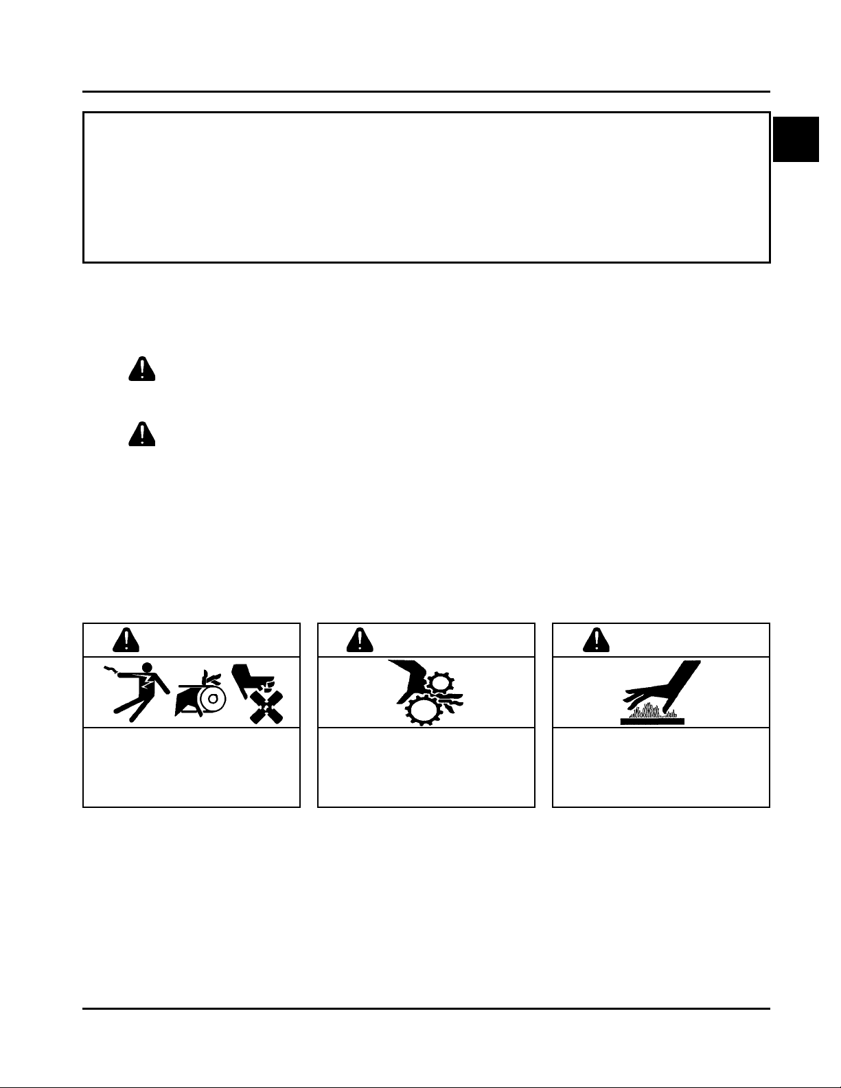
WARNING
Accidental Starts can cause
severe injury or death.
Disconnect and ground spark plug
leads before servicing.
Accidental St arts!
Disabling engine. Accidental
starting can cause severe injury
or death. Before working on the
engine or equipment, disable the
engine as follows: 1) Disconnect the
spark plug lead(s). 2) Disconnect
negative (-) battery cable from
battery .
WARNING
Rotating Parts can cause severe
injury.
Stay away while engine is in
operation.
Rotating Part s!
Keep hands, feet, hair, and
clothing away from all moving
parts to prevent injury. Never
operate the engine with covers,
shrouds, or guards removed.
Hot Parts can cause severe burns.
Do not touch engine while operating
or just after stopping.
Hot Parts!
Engine components can get
extremely hot from operation. To
prevent severe burns, do not
touch these areas while the
engine is running - or immediately
after it is turned off. Never operate
the engine with heat shields or
guards removed.
WARNING
1.1
Page 3
Section 1
Safety and General Information
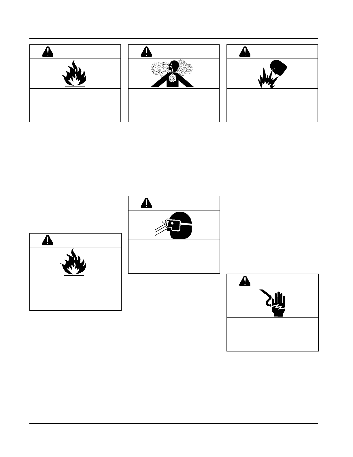
WARNING
Explosive Fuel can cause fires and
severe burns.
Stop engine before filling fuel tank.
Explosive Fuel!
Gasoline is extremely flammable
and its vapors can explode if
ignited. Store gasoline only in
approved containers, in well
ventilated, unoccupied buildings,
away from sparks or flames. Do not
fill the fuel tank while the engine is
hot or running, since spilled fuel
could ignite if it comes in contact
with hot parts or sparks from
ignition. Do not start the engine
near spilled fuel. Never use
gasoline as a cleaning agent.
WARNING
WARNING WARNING
Carbon Monoxide can cause
severe nausea, fainting or death.
Do not operate engine in closed or
confined area.
Lethal Exhaust Gases!
Engine exhaust gases contain
poisonous carbon monoxide.
Carbon monoxide is odorless,
colorless, and can cause death if
inhaled. Avoid inhaling exhaust
fumes, and never run the engine
in a closed building or confined
area.
WARNING
Uncoiling Spring can cause severe
injury.
Wear safety goggles or face
protection when servicing retractable
starter.
Explosive Gas can cause fires and
severe acid burns.
Charge battery only in a well
ventilated area. Keep sources of
ignition away.
Explosive Gas!
Batteries produce explosive
hydrogen gas while being
charged. To prevent a fire or
explosion, charge batteries only in
well ventilated areas. Keep
sparks, open flames, and other
sources of ignition away from the
battery at all times. Keep batteries
out of the reach of children.
Remove all jewelry when servicing
batteries.
Before disconnecting the negative
(-) ground cable, make sure all
switches are OFF. If ON, a spark
will occur at the ground cable
terminal which could cause an
explosion if hydrogen gas or
gasoline vapors are present.
Cleaning Solvents can cause
severe injury or death.
Use only in well ventilated areas
away from ignition sources.
Flammable Solvents!
Carburetor cleaners and solvents
are extremely flammable. Keep
sparks, flames, and other sources
of ignition away from the area.
Follow the cleaner manufacturer’s
warnings and instructions on its
proper and safe use. Never use
gasoline as a cleaning agent.
1.2
Spring Under T ension!
Retractable starters contain a
powerful, recoil spring that is under
tension. Always wear safety
goggles when servicing retractable
starters and carefully follow
instructions in the "Retractable
Starter" Section 7 for relieving
spring tension.
CAUTION
Electrical Shock can cause injury.
Do not touch wires while engine is
running.
Electrical Shock!
Never touch electrical wires or
components while the engine is
running. They can be sources of
electrical shock.
Page 4
Engine Identification Numbers
When ordering parts, or in any communication
involving an engine, always give the Model,
Specification and Serial Numbers, including letter
suffixes if there are any.
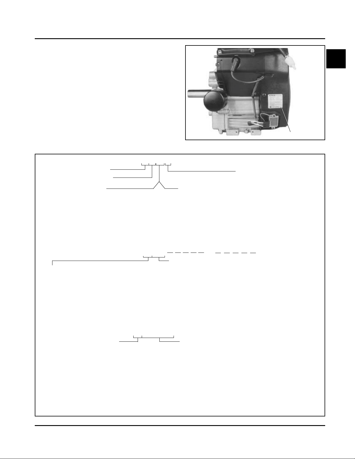
The engine identification numbers appear on a decal,
or decals, affixed to the engine shrouding. See Figure
1-1. An explanation of these numbers is shown in
Figure 1-2.
Section 1
Safety and General Information
1
Identification Decal
Figure 1-1. Engine Identification Decal Location.
A. Model No.
Command Engine
Horizontal Crankshaft
Numerical Designation
730
740
745
B. Spec. No.
Engine Model Code
Code Model
62 CH18
64 CH20
66 CH22 (624 cc)
68 CH25
76 CH22/23 (674 cc)
78 CH26
C H 18 S
or
62500
Horsepower
17 = 17 HP
18 = 18 HP
20 = 20 HP
22 = 22 HP
23 = 23 HP
25 = 25 HP
26 = 26 HP
Variation of
Basic Engine
or
Version Code
S = Electric Start
CH730-0001
CH740-0001
CH745-0001
Complete Spec Number
(Incorporating Model
No. with V ariation No. of
Basic Spec.)
C. Serial No.
Year Manufactured Code
Code Year
21 1991
22 1992
23 1993
24 1994
25 1995
26 1996
27 1997
28 1998
29 1999
Figure 1-2. Explanation of Engine Identification Numbers.
3305810334
Factory Code
Code Year
30 2000
31 2001
32 2002
33 2003
34 2004
35 2005
1.3
Page 5
Section 1
Safety and General Information
Oil Recommendations
Using the proper type and weight of oil in the crankcase
is extremely important. So is checking oil daily and
changing oil regularly . Failure to use the correct oil, or
using dirty oil, causes premature engine wear and failure.
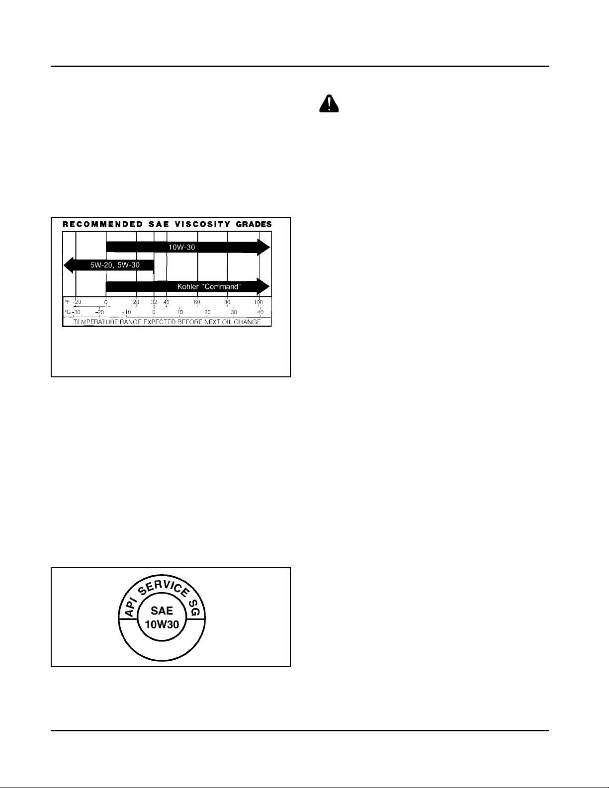
Oil Type
Use high-quality detergent oil of API (American
Petroleum Institute) Service Class SG, SH, SJ or
higher. Select the viscosity based on the air temperature
at the time of operation as shown in the following table.
**
*
*Use of synthetic oil having 5W-20 or 5W-30 rating is
acceptable, up to 40°F.
**Synthetic oils will provide better starting in extreme
cold (below -10°F).
NOTE: Using other than service class SG, SH, SJ or
higher oil or extending oil change intervals
longer than recommended can cause engine
damage.
NOTE: Synthetic oils meeting the listed classifications
may be used with oil changes performed at the
recommended intervals. However, to allow
piston rings to properly seat, a new or rebuilt
engine should be operated for at least 50 hours
using standard petroleum based oil before
switching to synthetic oil.
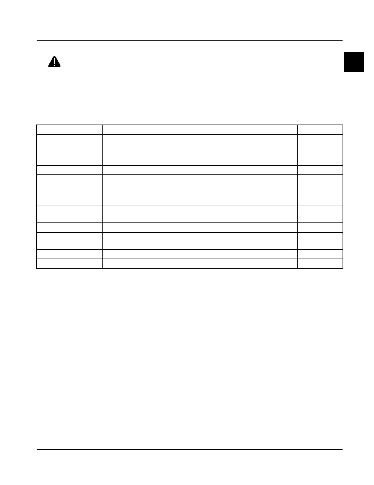
A logo or symbol on oil cont ainers identifies the API
service class and SAE viscosity grade. See Figure 1-3.
Fuel Recommendations
WARNING: Explosive Fuel!
Gasoline is extremely flammable and its vapors can
explode if ignited. Before servicing the fuel system,
make sure there are no sparks, open flames or other
sources of ignition nearby as these can ignite gasoline
vapors. Disconnect and ground the spark plug leads to
prevent the possibility of sparks from the ignition
system.
General Recommendations
Purchase gasoline in small quantities and store in
clean, approved containers. A cont ainer with a capacity
of 2 gallons or less with a pouring spout is
recommended. Such a container is easier to handle
and helps eliminate spillage during refueling.
Do not use gasoline left over from the previous
season, to minimize gum deposits in your fuel system
and to ensure easy starting.
Do not add oil to the gasoline.
Do not overfill the fuel tank. Leave room for the fuel to
expand.
Fuel Type
For best results, use only clean, fresh, unleaded
gasoline with a pump sticker octane rating of 87 or
higher. In countries using the Research method, it
should be 90 octane minimum.
Unleaded gasoline is recommended as it leaves less
combustion chamber deposits and reduces harmful
exhaust emissions. Leaded gasoline is not
recommended and must not be used on EFI engines,
or on other models where exhaust emissions are
regulated.
Figure 1-3. Oil Container Logo.
Refer to Section 6 - “Lubrication System” for detailed
procedures on checking the oil, changing the oil and
changing the oil filter.
1.4
Gasoline/Alcohol blends
Gasohol (up to 10% ethyl alcohol, 90% unleaded
gasoline by volume) is approved as a fuel for Kohler
engines. Other gasoline/alcohol blends are not
approved.
Gasoline/Ether blends
Methyl T ertiary Butyl Ether (MTBE) and unleaded
gasoline blends (up to a maximum of 15% MTBE by
volume) are approved as a fuel for Kohler engines. Other
gasoline/ether blends are not approved.
Page 6
Periodic Maintenance Instructions
Section 1
Safety and General Information
WARNING: Accident al Starts!
Disabling engine. Accidental starting can cause severe injury or death. Before working on the engine or
equipment, disable the engine as follows: 1) Disconnect the spark plug lead(s). 2) Disconnect negative (-) battery
cable from battery .
Maintenance Schedule
These required maintenance procedures should be performed at the frequency stated in the table. They should also
be included as part of any seasonal tune-up.
Maintenance Required Refer to:Frequency
• Fill fuel tank. Section 5
Daily or Before
Starting Engine
Every 25 Hours
Every 100 Hours
Every 200 Hours
Every 250 Hours
Annually or
Every 500 Hours
Every 500 Hours
Every 1500 Hours
1
Perform these maintenance procedures more frequently under extremely dusty , dirty conditions.
2
Have a Kohler Engine Service Dealer perform this service.
3
Cleanout Kits 25 755 20-S (black) or 25 755 21-S (gold) allow cooling areas to be cleaned without removing
shrouds.
• Check oil level. Section 6
• Check air cleaner for dirty1, loose, or damaged parts. Section 4
• Check air intake and cooling areas, clean as necessary1. Section 4
• Service precleaner element1. Section 4
• Replace air cleaner element1. Section 4
• Change oil. (More frequently under severe conditions.) Section 6
• Remove cooling shrouds and clean cooling areas
• Check oil cooler fins, clean as necessary (if equipped). Section 6
• Check spark plug condition and gap. Section 8
• Change oil filter. Section 6
• Replace heavy-duty air cleaner element and check inner element1. Section 4
• Have bendix starter drive serviced2. Section 8
• Have solenoid shift starter disassembled and cleaned2. Section 8
• Have crankshaft spline lubricated2. Section 2
• Replace fuel filter1 (EFI engines). Section 5B
1,3
. Section 4
1
Storage
If the engine will be out of service for two months or
more, use the following storage procedure.
1. Clean the exterior surfaces of the engine. On
Electronic Fuel Injected (EFI) engines, avoid
spraying water at the wiring harness or any of the
electrical components.
2. Change the oil and oil filter while the engine is still
warm from operation. See “Change Oil and Oil
Filter” in Section 6.
3. The fuel system must be completely emptied, or
the gasoline must be treated with a stabilizer to
prevent deterioration. If you choose to use a
stabilizer , follow the manufacturer’s
recommendations, and add the correct amount
for the capacity of the fuel system.
Fill the fuel tank with clean, fresh gasoline. Run
the engine for 2 to 3 minutes to get stabilized fuel
into the rest of the system. Close the fuel shut-off
valve when the unit is being stored or transported.
To empty the system, run the engine until the tank
and the system are empty.
4. Remove the spark plugs and add one tablespoon
of engine oil into each spark plug hole. Install the
spark plugs, but do not connect the plug leads.
Crank the engine two or three revolutions.
5. On equipment with an EFI engine, disconnect the
battery or use a battery minder to keep the battery
charged during storage.
6. Store the engine in a clean, dry place.
1.5
Page 7
Section 1
Safety and General Information
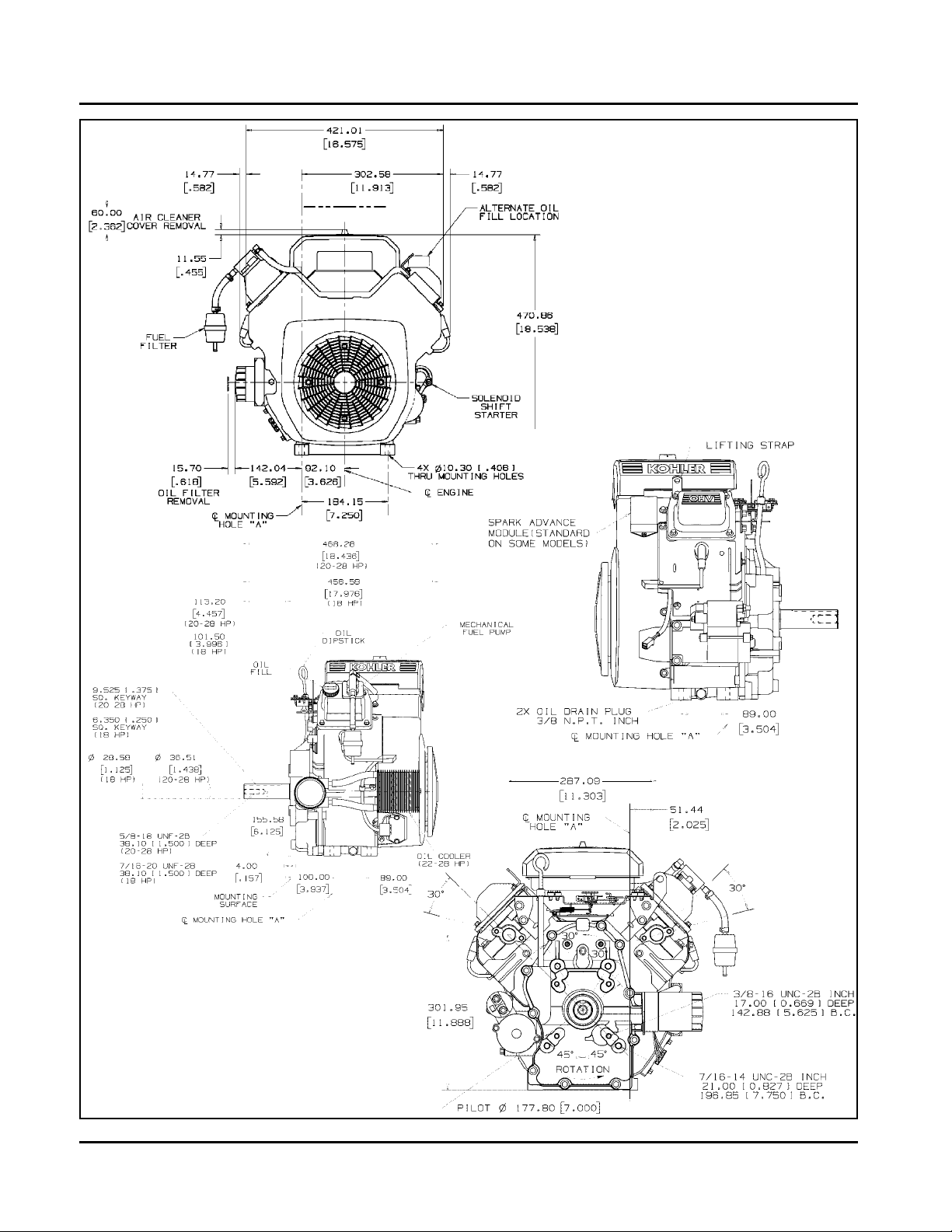
Dimensions in millimeters.
Inch equivalents shown in ().
Figure 1-4. Typical Engine Dimensions CH Series with Standard Flat Air Cleaner.
1.6
Page 8
Section 1
Safety and General Information
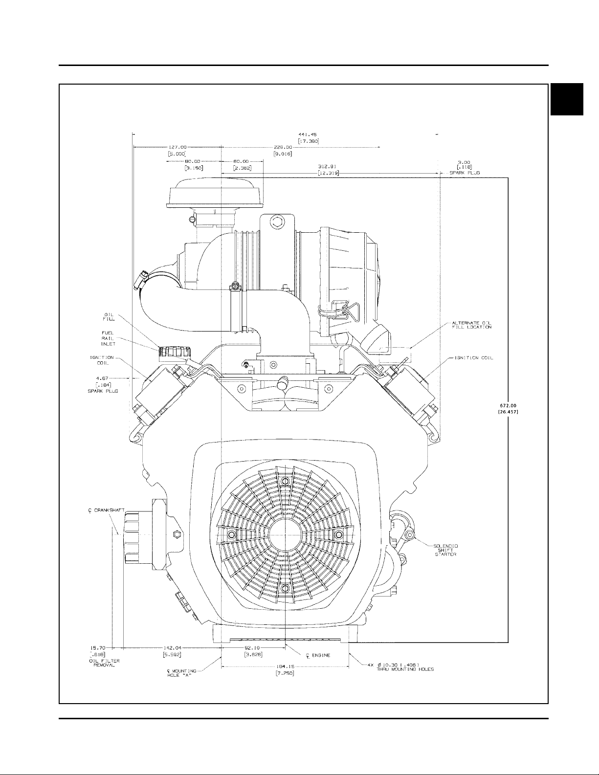
Dimensions in millimeters.
Inch equivalents shown in ().
1
Figure 1-5. T ypical Engine Dimensions CH EFI Series with Heavy-Duty Air Cleaner.
1.7
Page 9

Section 1
Safety and General Information
General Specifications¹
Power (@ 3600 RPM, corrected to SAE J1995)
CH18............................................................................................................................13.4 kW (18 HP)
CH20............................................................................................................................14.9 kW (20 HP)
CH22/23....................................................................................................................... 16.4 kW (22 HP)
CH25, CH730...............................................................................................................18.4 kW (25 HP)
CH26............................................................................................................................19.4 kW (26 HP)
CH740..........................................................................................................................20.1 kW (27 HP)
CH745..........................................................................................................................20.9 kW (28 HP)
Peak Torque
CH18 - @ 2200 RPM ................................................................................................... 44.4 N·m (32.8 ft. lb.)
CH20 - @ 2600 RPM ................................................................................................... 44.2 N·m (32.6 ft. lb.)
CH22/23 - @ 2200 RPM ..............................................................................................51.7 N·m (38.2 ft. lb.)
CH25, CH730 - @ 2800 RPM ...................................................................................... 54.1 N·m (39.9 ft. lb.)
CH26 - @ 2800 RPM ................................................................................................... 54.2 N·m (40.0 ft. lb.)
CH740 - @ 3000 RPM ................................................................................................. 57.9 N·m (42.7 ft. lb.)
CH745 - @ 2200 RPM ................................................................................................. 60.7 N·m (44.8 ft. lb.)
Bore
CH18, CH20, CH22 (624 cc)........................................................................................ 77 mm (3.03 in.)
CH22/23 (674 cc).........................................................................................................80 mm (3.15 in.)
CH25, CH26, CH730-745.............................................................................................83 mm (3.27 in.)
Stroke.................................................................................................................................67 mm (2.64 in.)
Displacement
CH18, CH20, CH22 (624 cc)........................................................................................ 624 cc (38 cu. in.)
CH22/23 (674 cc).........................................................................................................674 cc (41 cu. in.)
CH25, CH26, CH730-745.............................................................................................725 cc (44 cu. in.)
Compression Ratio
CH18, CH20, CH22/23.................................................................................................8.5:1
CH25, CH26, CH730-745.............................................................................................9.0:1
Dry Weight
CH18, CH20, CH22/23................................................................................................. 41 kg (90 lb.)
CH25, CH26, CH730-745.............................................................................................43 kg (94 lb.)
Oil Capacity (with filter)
CH18, CH20, CH22/23, CH25, CH26, CH730-745 ......................................................1.9 L (2.0 U.S. qt.)
Angle of Operation - Maximum (At Full Oil Level) All Directions ......................................... 25°
Blower Housing and Sheet Metal
M5 Fasteners Torque..........................................................................................................4.0 N·m (35 in. lb.)
M6 Fasteners Torque..........................................................................................................6.8 N·m (60 in. lb.)
Rectifier-Regulator Fastener Torque...................................................................................4.0 N·m (35 in. lb.)
¹V alues are in Metric units. V alues in parentheses are English equivalents. Lubricate threads with engine oil prior
to assembly.
1.8
Page 10

Section 1
Safety and General Information
Camshaft
End Play (With Shim) .................................................................................. 0.076/0.127 mm (0.0030/0.0050 in.)
Running Clearance...................................................................................... 0.025/0.063 mm (0.0010/0.0025 in.)
Bore I.D.
New....................................................................................................... 20.000/20.025 mm (0.7874/0.7884 in.)
Max. Wear Limit.................................................................................... 20.038 mm (0.7889 in.)
Camshaft Bearing Surface O.D.
New....................................................................................................... 19.962/19.975 mm (0.7859/0.7864 in.)
Max. Wear Limit.................................................................................... 19.959 mm (0.7858 in.)
Carburetor and Intake Manifold
Intake Manifold Mounting Fastener Torque
Torque in Two Stages............................................................................ initially to 7.4 N·m (66 in. lb.)
finally to 9.9 N·m (88 in. lb.)
Carburetor Mounting Screw Torque M6 ....................................................... 6.2-7.3 N·m (55-65 in. lb.)
1
Adapter (for Heavy Duty Air Cleaner) Mounting Fastener Torque ................ 7.3 N·m (65 in. lb.)
Connecting Rod
Cap Fastener Torque (torque in increments)
8 mm straight shank.............................................................................. 22.7 N·m (200 in. lb.)
8 mm step-down ................................................................................... 14.7 N·m (130 in. lb.)
6 mm straight shank.............................................................................. 1 1.3 N·m (100 in. lb.)
Connecting Rod-to-Crankpin Running Clearance
New....................................................................................................... 0.030/0.055 mm (0.0012/0.0022 in.)
Max. Wear Limit.................................................................................... 0.070 mm (0.0028 in.)
Connecting Rod-to-Crankpin Side Clearance .............................................. 0.26/0.63 mm (0.0102/0.0248 in.)
Connecting Rod-to-Piston Pin Running Clearance ...................................... 0.015/0.028 mm (0.0006/0.001 1 in.)
Piston Pin End I.D.
New....................................................................................................... 17.015/17.023 mm (0.6699/0.6702 in.)
Max. Wear Limit.................................................................................... 17.036 mm (0.6707 in.)
Crankcase
Governor Cross Shaft Bore I.D.
6 mm Shaft
New ................................................................................................... 6.025/6.050 mm (0.2372/0.2382 in.)
Max. Wear Limit................................................................................. 6.063 mm (0.2387 in.)
8 mm Shaft
New ................................................................................................... 8.025/8.075 mm (0.3159/0.3179 in.)
Max. Wear Limit................................................................................. 8.088 mm (0.3184 in.)
Breather Cover Fastener Torque ................................................................. 7.3 N·m (65 in. lb.)
Oil Drain Plug T orque ................................................................................... 13.6 N·m (10 ft. lb.)
1.9
Page 11

Section 1
Safety and General Information
Closure Plate
Closure Plate Fastener T orque .............................................................. 24.4 N·m (216 in. lb.)
Crankshaft
End Play (Free) .................................................................................... 0.070/0.590 mm (0.0028/0.0230 in.)
End Play (With Thrust Bearing Components) ....................................... 0.070/0.270 mm (0.0028/0.0100 in.)
Except CH25 Engines Below Serial No. 2403500008 .................... 0.050/0.750 mm (0.0020/0.0295 in.)
Crankshaft Bore (In Crankcase)
New................................................................................................ 40.965/41.003 mm (1.6128/1.6143 in.)
Max. Wear Limit ............................................................................. 41.016 mm (1.6148 in.)
Crankshaft to Sleeve Bearing (Crankcase)
Running Clearance - New................................................................ 0.03/0.09 mm (0.0012/0.0035 in.)
Crankshaft Bore (In Closure Plate) - New .............................................. 40.987/40.974 mm (1.6136/1.6131 in.)
Crankshaft Bore (In Closure Plate)-to-Crankshaft
Running Clearance - New .............................................................. 0.039/0.074 mm (0.0015/0.0029 in.)
Flywheel End Main Bearing Journal
O.D. - New ..................................................................................... 40.913/40.935 mm (1.6107/1.6116 in.)
O.D. - Max. Wear Limit .................................................................. 40.84 mm (1.608 in.)
Max. Taper ..................................................................................... 0.022 mm (0.0009 in.)
Max. Out-of-Round ........................................................................ 0.025 mm (0.0010 in.)
Closure Plate End Main Bearing Journal
O.D. - New ..................................................................................... 40.913/40.935 mm (1.6107/1.6116 in.)
O.D. - Max. Wear Limit .................................................................. 40.84 mm (1.608 in.)
Max. Taper ..................................................................................... 0.022 mm (0.0009 in.)
Max. Out-of-Round ........................................................................ 0.025 mm (0.0010 in.)
Connecting Rod Journal
O.D. - New ..................................................................................... 35.955/35.973 mm (1.4156/1.4163 in.)
O.D. - Max. Wear Limit .................................................................. 35.94 mm (1.415 in.)
Max. Taper ..................................................................................... 0.018 mm (0.0007 in.)
Max. Out-of-Round ........................................................................ 0.025 mm (0.0010 in.)
Crankshaft T.I.R.
PTO End, Crank in Engine............................................................. 0.279 mm (0.0110 in.)
Entire Crank, in V-Blocks ............................................................... 0.10 mm (0.0039 in.)
Cylinder Bore
Cylinder Bore I.D.
New - CH18, CH20, CH22 (624 cc) ............................................... 77.000/77.025 mm (3.0315/3.0325 in.)
New - CH22/23 (674 cc)................................................................. 80.000/80.025 mm (3.1496/3.1506 in.)
New - CH25, CH26, CH730-745 .................................................... 82.988/83.013 mm (3.2672/3.2682 in.)
Max. Wear Limit - CH18, CH20, CH22 (624 cc)............................. 77.063 mm (3.0340 in.)
Max. Wear Limit - CH22/23 (674 cc).............................................. 80.065 mm (3.1522 in.)
Max. Wear Limit - CH25, CH26, CH730-745.................................. 83.051 mm (3.2697 in.)
Max. Out-of-Round ........................................................................ 0.12 mm (0.0047 in.)
Max. Taper ..................................................................................... 0.05 mm (0.0020 in.)
1.10
Page 12

Safety and General Information
Cylinder Head
Cylinder Head Fastener T orque
Hex. Flange Nut - Torque in T wo Stages.......................................... initially to 16.9 N·m (150 in. lb.)
finally to 33.9 N·m (300 in. lb.)
Head Bolt - Torque in Two S t ages .................................................. initially to 22.6 N·m (200 in. lb.)
finally to 41.8 N·m (370 in. lb.)
Max. Out-of-Flatness............................................................................ 0.076 mm (0.003 in.)
Rocker Arm Screw T orque.................................................................... 11.3 N·m (100 in. lb.)
Fan/Flywheel
Fan Fastener Torque ............................................................................ 9.9 N·m (88 in. lb.)
Flywheel Retaining Screw Torque......................................................... 66.4 N·m (49 ft. lb.)
Governor
Governor Cross Shaft-to-Crankcase Running Clearance
6 mm Shaft .................................................................................... 0.013/0.075 mm (0.0005/0.0030 in.)
8 mm Shaft .................................................................................... 0.025/0.126 mm (0.0009/0.0049 in.)
Section 1
1
Governor Cross Shaft O.D.
6 mm Shaft
New ............................................................................................ 5.975/6.012 mm (0.2352/0.2367 in.)
Max. Wear Limit.......................................................................... 5.962 mm (0.2347 in.)
8 mm Shaft
New ............................................................................................ 7.949/8.000 mm (0.3129/.3149 in.)
Max. Wear Limit.......................................................................... 7.936 mm (0.3124 in.)
Governor Gear Shaft-to-Governor Gear Running Clearance................ 0.015/0.140 mm (0.0006/0.0055 in.)
Governor Gear Shaft O.D.
New................................................................................................ 5.990/6.000 mm (0.2358/0.2362 in.)
Max. Wear Limit............................................................................. 5.977 mm (0.2353 in.)
Governor Lever Nut Torque .................................................................. 6.8 N·m (60 in. lb.)
Ignition
Sp ark Plug Type (Champion® or Equivalent)......................................... RC12YC or Platinum 3071
Sp ark Plug Gap .................................................................................... 0.76 mm (0.030 in.)
Sp ark Plug Torque ................................................................................ 24.4-29.8 N·m (18-22 ft. lb.)
Ignition Module Air Gap ........................................................................ 0.28/0.33 mm (0.01 1/0.013 in.)
Ignition Module Fastener Torque .......................................................... 4.0-6.2 N·m (35-55 in. lb.)
Speed Sensor Air Gap (EFI engines) .................................................... 1.250/1.750 mm (0.049/0.068 in.)
1.11
Page 13

Section 1
Safety and General Information
Muffler
Muffler Retaining Nut Torque.................................................................. 24.4 N·m (216 in. lb.)
Oil Filter
Oil Filter Torque .................................................................................... 10.4-12.7 N·m (90-1 10 in. lb.)
Oil Cooler
Oil Cooler/Adapter Nipple Torque ......................................................... 27 N·m (20 ft. lb.)
Piston, Piston Rings, and Piston Pin
Piston-to-Piston Pin Running Clearance............................................... 0.006/0.017 mm (0.0002/0.0007 in.)
Piston Pin Bore I.D.
New................................................................................................ 17.006/17.012 mm (0.6695/0.6698 in.)
Max. Wear Limit ............................................................................. 17.025 mm (0.6703 in.)
Piston Pin O.D.
New................................................................................................ 16.995/17.000 mm (0.6691/0.6693 in.)
Max. Wear Limit ............................................................................. 16.994 mm (0.6691 in.)
Top Compression Ring-to-Groove Side Clearance
CH18, CH20, CH22 (624 cc).......................................................... 0.040/0.080 mm (0.0016/0.0031 in.)
CH22/23 (674 cc)........................................................................... 0.030/0.076 mm (0.0012/0.0030 in.)
CH25, CH26, CH730-745............................................................... 0.025/0.048 mm (0.0010/0.0019 in.)
Middle Compression Ring-to-Groove Side Clearance
CH18, CH20, CH22 (624 cc).......................................................... 0.040/0.080 mm (0.0016/0.0031 in.)
CH22/23 (674 cc)........................................................................... 0.030/0.076 mm (0.0012/0.0030 in.)
CH25, CH26, CH730-745............................................................... 0.015/0.037 mm (0.0006/0.0015 in.)
Oil Control Ring-to-Groove Side Clearance
CH18, CH20, CH22 (624 cc).......................................................... 0.060/0.202 mm (0.0024/0.0080 in.)
CH22/23 (674 cc)........................................................................... 0.046/0.196 mm (0.0018/0.0077 in.)
CH25, CH26, CH730-745............................................................... 0.026/0.176 mm (0.0010/0.0070 in.)
Top and Center Compression Ring End Gap
New Bore - CH18, CH20, CH22 (624 cc) ....................................... 0.25/0.45 mm (0.0098/0.0177 in.)
New Bore - CH22 (674 cc) ............................................................. 0.18/0.46 mm (0.0071/0.0181 in.)
New Bore - CH25, CH26, CH730-745............................................ 0.25/0.56 mm (0.0100/0.0224 in.)
Used Bore (Max.) - CH18, CH20, CH22 (624 cc)........................... 0.77 mm (0.030 in.)
Used Bore (Max.) - CH22/23 (674 cc)............................................ 0.80 mm (0.0315 in.)
Used Bore (Max.) - CH25, CH26, CH730-745 ............................... 0.94 mm (0.037 in.)
Piston Thrust Face O.D.²
New - CH18, CH20, CH22 (624 cc) ............................................... 76.967/76.985 mm (3.0302/3.0309 in.)
New - CH22/23 (674 cc)................................................................. 79.963/79.979 mm (3.1481/3.1488 in.)
New - CH25, CH26, CH730-745 .................................................... 82.986 mm (3.3194 in.)
Max. Wear Limit - CH18, CH20, CH22 (624 cc)............................. 76.840 mm (3.0252 in.)
Max. Wear Limit - CH22 (674 cc)................................................... 79.831 mm (3.1430 in.)
Max. Wear Limit - CH25, CH26, CH730-745.................................. 82.841 mm (3.3136 in.)
²Measure 6 mm (0.236 in.) above the bottom of the piston skirt at right angles to the piston pin.
1.12
Page 14

Safety and General Information
Piston, Piston Rings, and Piston Pin cont.
Piston Thrust Face-to-Cylinder Bore² Running Clearance
New - CH18, CH20, CH22 (624 cc) ............................................... 0.014/0.057 mm (0.0005/0.0022 in.)
New - CH22/23 (674 cc)................................................................. 0.021/0.062 mm (0.0008/0.0024 in.)
New - CH25, CH26, CH730-745 .................................................... 0.001/0.045 mm (0.039/0.0018 in.)
Speed Control Bracket
Fastener T orque ................................................................................... 7.3-10.7 N·m (65-95 in. lb.)
Starter Assembly
Thru Bolt Torque
UTE/Johnson Electric, Eaton (Inertia Drive) ................................... 4.5-5.7 N·m (40-50 in. lb.)
Nippondenso (Solenoid Shift)......................................................... 4.5-7.5 N·m (40-84 in. lb.)
Delco-Remy (Solenoid Shift) .......................................................... 5.6-9.0 N·m (49-79 in. lb.)
Mounting Screw Torque (All)................................................................. 15.3 N·m (135 in. lb.)
Brush Holder Mounting Screw Torque
Delco-Remy Starter........................................................................ 2.5-3.3 N·m (22-29 in. lb.)
Solenoid (Starter)
Mounting Hardware Torque
Nippondenso Starter .......................................................................6.0-9.0 N·m (53-79 in. lb.)
Delco-Remy Starter.........................................................................4.0-6.0 N·m (35-53 in. lb.)
Nut, Positive (+) Brush Lead Torque
Nippondenso Starter .......................................................................8.0-12.0 N·m (71-106 in. lb.)
Delco-Remy Starter.........................................................................8.0-11.0 N·m (71-97 in. lb.)
Section 1
1
Stator
Mounting Screw Torque ........................................................................ 6.2 N·m (55 in. lb.)
Throttle/Choke Controls
Governor Control Lever Fastener Torque ............................................. 9.9 N·m (88 in. lb.)
Valve Cover
V alve Cover Fastener Torque
Gasket Style Cover ........................................................................ 3.4 N·m (30 in. lb.)
Black O-Ring Style Cover
w/Shoulder Screws.................................................................... 5.6 N·m (50 in. lb.)
w/Flange Screws and Spacers .................................................. 9.9 N·m (88 in. lb.)
Brown O-Ring Style Cover w/Integral Metal Spacers...................... 9.9 N·m (88 in. lb.)
Valves and Valve Lifters
Hydraulic V alve Lifter to Crankcase Running Clearance........................0.0241/0.0501 mm (0.0009/0.0020 in.)
Intake V alve S tem-to-Valve Guide Running Clearance ......................... 0.038/0.076 mm (0.0015/0.0030 in.)
Exhaust V alve S tem-to-Valve Guide Running Clearance ...................... 0.050/0.088 mm (0.0020/0.0035 in.)
Intake V alve Guide I.D.
New ................................................................................................ 7.038/7.058 mm (0.2771/0.2779 in.)
Max. Wear Limit............................................................................. 7.135 mm (0.2809 in.)
1.13
Page 15
Section 1
Safety and General Information
Valves and Valve Lifters cont.
Exhaust V alve Guide I.D.
New................................................................................................ 7.038/7.058 mm (0.2771/0.2779 in.)
Max. Wear Limit ............................................................................. 7.159 mm (0.2819 in.)
V alve Guide Reamer Size
Standard......................................................................................... 7.048 mm (0.2775 in.)
0.25 mm O.S.................................................................................. 7.298 mm (0.2873 in.)
Intake V alve Minimum Lif t..................................................................... 8.07 mm (0.3177 in.)
Exhaust V alve Minimum Lift.................................................................. 8.07 mm (0.3177 in.)
Nominal V alve Seat Angle ..................................................................... 45°
General Torque Values
Metric Fastener T orque Recommendations for St andard Applications
Tightening Torque: N·m (in. lb.) + or - 10%
Property Class
4.8
Size
M4 1.2 (1 1) 1.7 (15) 2.9 (26) 4.1 (36) 5.0 (44) 2.0 (18)
M5 2.5 (22) 3.2 (28) 5.8 (51) 8.1 (72) 9.7 (86) 4.0 (35)
M6 4.3 (38) 5.7 (50) 9.9 (88) 14.0 (124) 16.5 (146) 6.8 (60)
M8 10.5 (93) 13.6 (120) 24.4 (216) 33.9 (300) 40.7 (360) 17.0 (150)
5.8
8.8 10.9 12.9
Noncritical
Fasteners
Into Aluminum
Tightening Torque: N·m (ft. lb.) + or - 10%
Property Class
4.8
M10 21.7 (16) 27.1 (20) 47.5 (35) 66.4 (49) 81.4 (60) 33.9 (25)
M12 36.6 (27) 47.5 (35) 82.7 (61) 116.6 (86) 139.7 (103) 61.0 (45)
M14 58.3 (43) 76.4 (55) 131.5 (97) 184.4 (136) 219.7 (162) 94.9 (70)
5.8
8.8
10.9
12.9
Noncritical
Fasteners
Into Aluminum
1.14
Page 16
Safety and General Information
English Fastener T orque Recommendations for St andard Applications
Section 1
Tightening Torque: N·m (in. lb.) + or - 20%
Bolts, Screws, Nuts and Fasteners
Assembled Into Cast Iron or Steel
Grade 2 Grade 5 Grade 8
Size
8-32 2.3 (20) 2.8 (25) --------- 2.3 (20)
10-24 3.6 (32) 4.5 (40) --------- 3.6 (32)
10-32 3.6 (32) 4.5 (40) --------- ---------
1/4-20 7.9 (70) 13.0 (1 15) 18.7 (165) 7.9 (70)
1/4-28 9.6 (85) 15.8 (140) 22.6 (200) ---------
5/16-18 17.0 (150) 28.3 (250) 39.6 (350) 17.0 (150)
5/16-24 18.7 (165) 30.5 (270) --------- ---------
3/8-16 29.4 (260) --------- --------- ---------
3/8-24 33.9 (300) --------- --------- ---------
Grade 2 or 5
Fasteners Into
Aluminum
Tightening Torque: N·m (ft. lb.) + or - 20%
Size
5/16-24 --------- ---------- 40.7 (30) --------3/8-16 --------- 47.5 (35) 67.8 (50) --------3/8-24 --------- 54.2 (40) 81.4 (60) --------7/16-14 47.5 (35) 74.6 (55) 108.5 (80) --------7/16-20 61.0 (45) 101.7 (75) 142.4 (105) --------1/2-13 67.8 (50) 108.5 (80) 155.9 (115) --------1/2-20 94.9 (70) 142.4 (105) 223.7 (165) --------9/16-12 101.7 (75) 169.5 (125) 237.3 (175) --------9/16-18 135.6 (100) 223.7 (165) 311.9 (230) --------5/8-11 149.2 (110) 244.1 (180) 352.6 (260) --------5/8-18 189.8 (140) 31 1.9 (230) 447.5 (330) --------3/4-10 199.3 (150) 332.2 (245) 474.6 (350) --------3/4-16 271.2 (200) 440.7 (325) 637.3 (470) ---------
1
Torque
Conversions
N·m = in. lb. x 0.1 13
N·m = ft. lb. x 1.356
in. lb. = N·m x 8.85
ft. lb. = N·m x 0.737
1.15
Page 17

Section 1
Safety and General Information
1.16
Page 18
Section 2
Section 2
Special Tools
CH18-745
Special Tools
Certain quality tools are designed to help you perform specific disassembly , rep air, and reassembly procedures.
By using tools designed for the job, you can service engines easier, faster, and safer! In addition, you’ll increase
your service capabilities and customer satisfaction by decreasing engine downtime.
Kohler special tools are handled by SPX Corp., a division of Owatonna Tool Corp. (OTC). The tools are easy to
purchase by contacting SPX/OTC by phone, fax, or mail.
Phone: 1-800-533-0492
International: 1-507-455-7223
8:00 am – 8:00 pm EST
Some special tools for this engine are:
Camshaft Endplay Plate........................................................................................ KO1031
Flywheel Strap W rench ......................................................................................... NU10357
Flywheel Puller Kit................................................................................................. NU3226
Rocker Arm Spanner Wrench................................................................................ OEM6200
V alve Guide Reamer ............................................................................................. KO1026
Water Manometer ................................................................................................. KO1048
Cylinder Leakdown Tester ..................................................................................... KO3219
Ignition System Tester ........................................................................................... KO1046
Hydraulic Lifter Removal/Reinstallation Tool.......................................................... KO1044
St arter Service Kit ................................................................................................. KO3226
St arter Retaining Ring Tool.................................................................................... 25 761 18-S
V acuum Gauge ..................................................................................................... KO3223
Tachometer (Digital Inductive) ............................................................................... KO3216
Sp ark Advance Module (SAM) Tester ..................................................................... KO3222
Rectifier-Regulator T ester ....................................................................................... KO3221
Fax: 1-800-578-7375
1-586-578-7375
International: 1-507-455-7063
Mail: SPX Corp., OTC
28635 Mound Rd.
Warren, MI 48092-3499
2
Electronic Fuel Injection (EFI) Service T ools
EFI Service Kit ...................................................................................................... KO3217
Gauge Assembly ............................................................................................... KO3217-4
Pliers................................................................................................................. KO3217-5
Circuit Tester ..................................................................................................... KO3217-6
Jumper Plug, Red (for metal cased ECU) ......................................................... KO3217-7
Tee Valve Assembly .......................................................................................... KO3217-8
Jumper Plug, Blue (for plastic cased ECU) ....................................................... KO3217-9
Some of the specialty tools are shown and mentioned at various points in this manual. A complete catalog of
available tools may be ordered under Kohler Part No. TP-2546. The tool price list is available under Kohler Part No.
TP-2547.
2.1
Page 19
Section 2
Special Tools
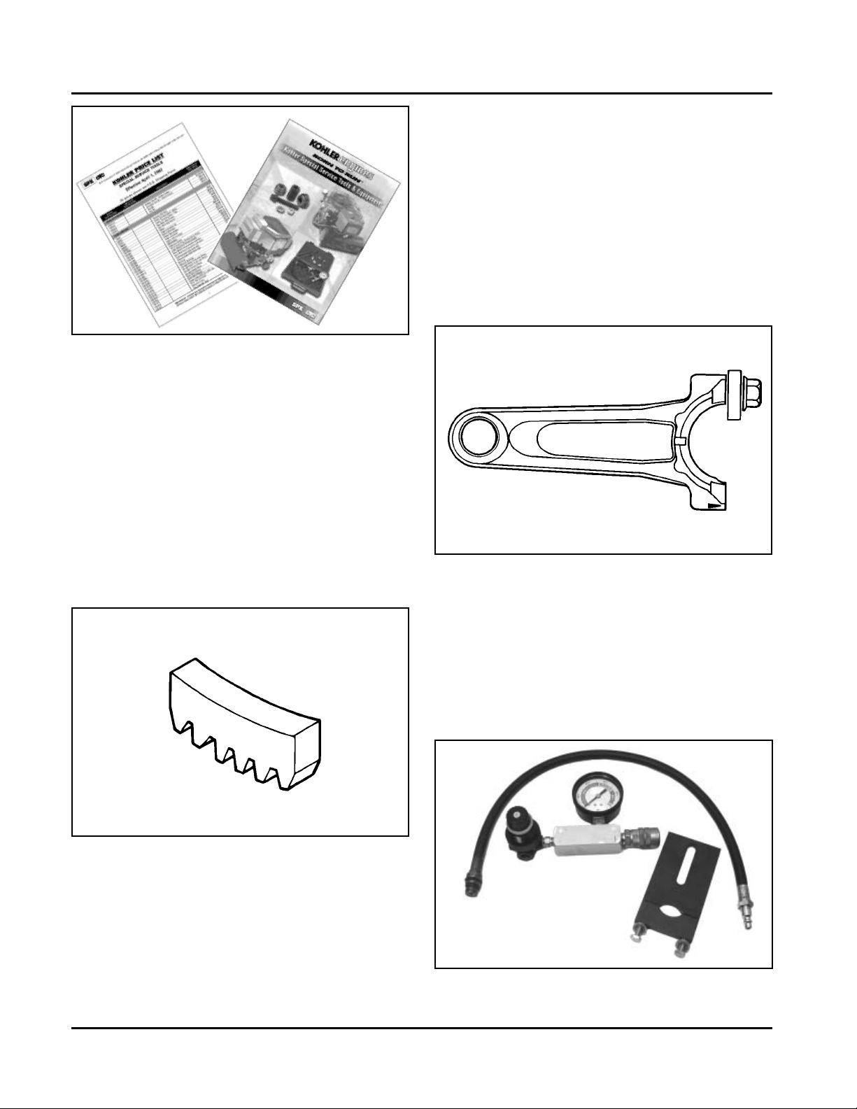
Figure 2-1. Tool Catalog and Price List.
Special Tools You Can Make
Flywheel Holding T ool
Flywheel removal and reinstallation becomes a “snap”
using a handy holding tool which can be made out of an
old “junk” flywheel ring gear as shown in Figure 2-2.
Using an abrasive cut-off wheel, cut out a six tooth
segment of the ring gear as shown. Grind off any burrs
or sharp edges. The segment can be used in place of a
strap wrench. Invert the segment and place it between
the ignition bosses on the crankcase so that the tool
teeth engage the flywheel ring gear teeth. The bosses
will “lock” the tool and flywheel in position for loosening,
tightening or removing with a puller.
Find a used connecting rod from a 10 HP or larger
engine. Remove and discard the rod cap. If it is a PosiLock rod, you will also need to remove the studs. If it is
a Command rod, you will need to grind off the aligning
steps, so the joint surface is flat. Find a 1 in. long
capscrew with the correct thread size to match the
threads in the connecting rod. Obtain a flat washer
with the correct I.D. to slip on the capscrew and an
O.D. of approximately 1 in. Kohler Part No. 12 468 05-S
can be used if you don’t have the right size on hand.
Assemble the capscrew and washer to the joint
surface of the rod, as shown in Figure 2-3.
Figure 2-3. Rocker Arm/Crankshaf t Tool.
Cylinder Leakdown Tester
A Cylinder Leakdown Tester (SPX Part No. KO3219
formerly Kohler 25 761 05-S) is a valuable alternate to a
compression test on these engines. See Figure 2-4. By
pressurizing the combustion chamber from an external
air source, this tool can determine if valves or rings are
leaking. Instructions for using this tester are found in
Section 3 of this manual.
Figure 2-2. Flywheel Holding Tool.
Rocker Arm/Crankshaft Tool
If you don’t have a spanner wrench to lift the rocker
arms or turn the crankshaft, you can make a tool for
doing this out of an old junk connecting rod.
2.2
Figure 2-4. Cylinder Leakdown Tester.
Page 20
RTV Silicone Sealant
RTV silicone sealant is used as a gasket between the
crankcase and closure plate.
Only oxime-based, oil resistant RTV sealants, such as
those listed below, are approved for use. Loctite® Nos.
5900 and 5910 are recommended for best sealing
characteristics.
Loctite® Ultra Blue 587
Loctite® Ultra Copper
Loctite® Ultra Black 598
Loctite® 5900 (Heavy Body)
Loctite® 5910
Section 2
Special Tools
2
Figure 2-6. Camshaft Break-in Lubricant.
NOTE: Always use fresh sealant. Using outdated
sealant can result in leakage.
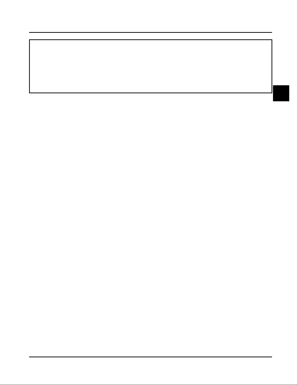
Loctite® 5900 is available in a 4 oz aerosol dispenser
with replacement tips under Kohler Part No.
25 597 07-S. See Figure 2-5.
Figure 2-5. Loctite® 5900 Aerosol Dispenser .
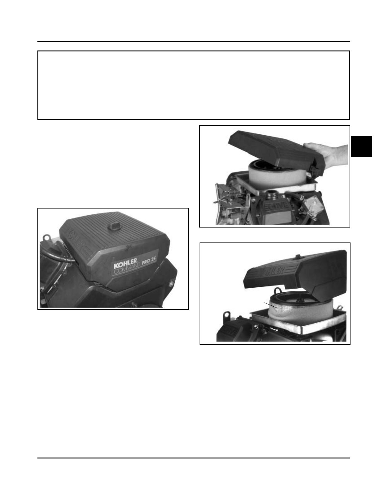
Camshaft Break-in Lubricant
Camshaft lubricant, Kohler Part No. 25 357 14-S
(V alspar ZZ613), should be used whenever a new
camshaft and lifters are installed for proper break-in
upon initial startup. Lubricant is included with each
replacement camshaft and lifter , or may also be
obtained separately in a 1/8 oz handy dispensing tube
by the part number listed. See Figure 2-6.
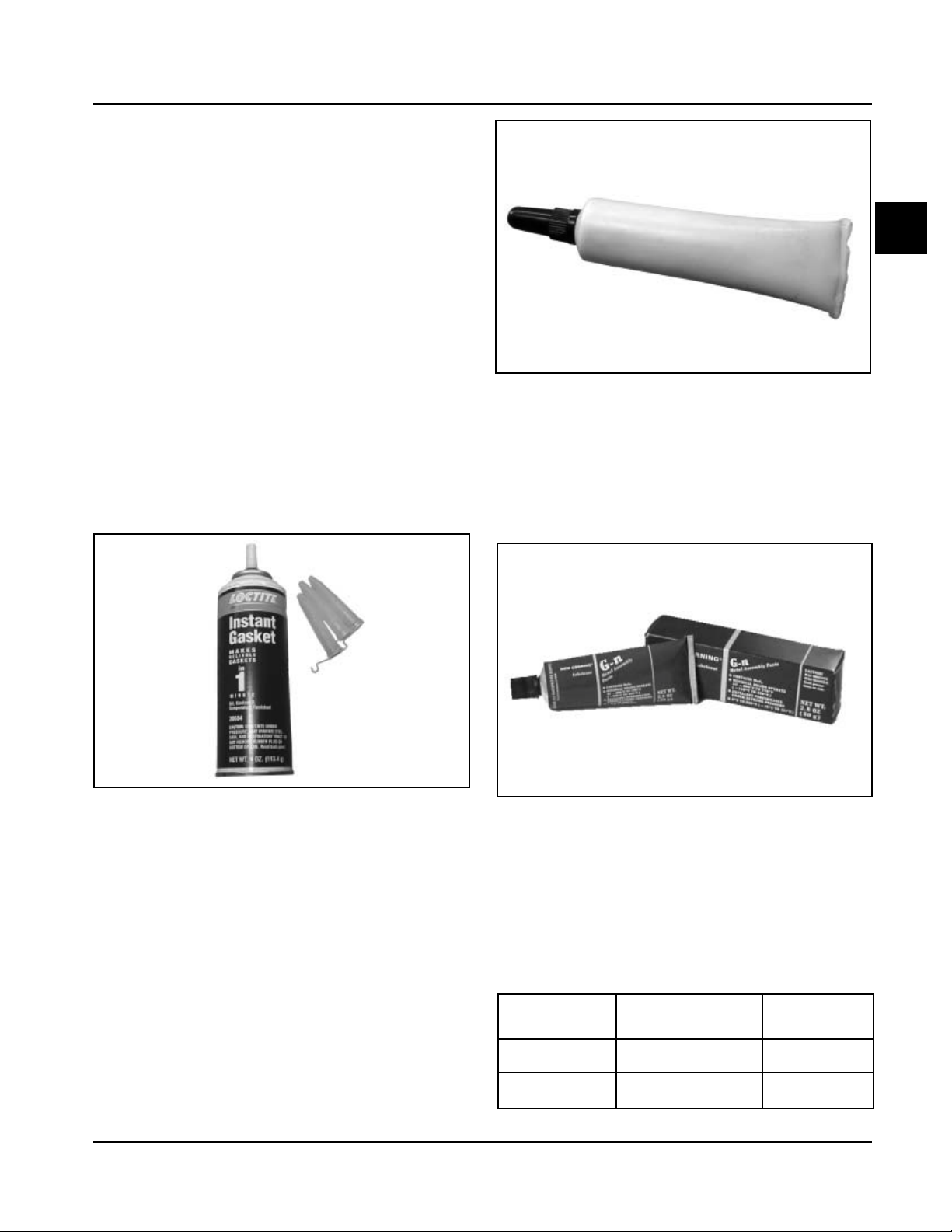
Spline Drive Lubricant
Special spline drive crankshaft lubricant Kohler Part No.
25 357 12-S is available in a 2.8 oz tube for use on all
spline drive applications. This lubricant provides proper
protection against wear-related damage. See Figure
2-7.
Figure 2-7. Crankshaft Spline Drive Lubricant.
Dielectric Grease
Dielectric grease is applied to the outside of the
terminal connections on the SMART -SP ARK™ ignition
modules to prevent formation of a moisture path and
arcing between the terminals. The chart below lists the
approved dielectric greases.
Dielectric Grease
Kohler
Part No.
Vendor
Vendor No./
Description
G.E./Novaguard
Fel-Pro
G661
Lubri-Sel
25 357 11-S
---
2.3
Page 21

Section 2
Special Tools
2.4
Page 22
Section 3
Troubleshooting
Troubleshooting Guide
When troubles occur, be sure to check the simple
causes which, at first, may seem too obvious to be
considered. For example, a starting problem could be
caused by an empty fuel tank.
Some general common causes of engine troubles are
listed below. Use these to locate the causing factors.
Refer to the specific section(s) within this service
manual for more detailed information.
Engine Cranks But Will Not Start
1. Empty fuel tank.
2. Fuel shut-off valve closed.
3. Poor fuel, dirt or water in the fuel system.
4. Clogged fuel line.
5. Sp ark plug lead(s) disconnected.
6. Key switch or kill switch in “off” position.
7. Faulty spark plugs.
8. Faulty ignition module(s).
9. SMART-SP ARK™ malfunction (applicable models).
10. Carburetor solenoid malfunction.
1 1. Diode in wiring harness failed in open circuit mode.
12. V acuum fuel pump malfunction, or oil in vacuum
hose.
13. Vacuum hose to fuel pump leaking/cracked.
14. Battery connected backwards.
Engine Start s But Does Not Keep Running
1. Restricted fuel tank cap vent.
2. Poor fuel, dirt or water in the fuel system.
3. Faulty or misadjusted choke or throttle controls.
4. Loose wires or connections that short the kill
terminal of ignition module to ground.
5. Faulty cylinder head gasket.
6. Faulty carburetor.
7. V acuum fuel pump malfunction, or oil in vacuum
hose.
8. Leaking/cracked vacuum hose to fuel pump.
9. Intake system leak.
10. Diode in wiring harness failed in open circuit mode.
Section 3
Troubleshooting
Engine Starts Hard
1. PTO drive is engaged.
2. Dirt or water in the fuel system.
3. Clogged fuel line.
4. Loose or faulty wires or connections.
5. Faulty or misadjusted choke or throttle controls.
6. Faulty spark plugs.
7. Low compression.
8. Weak spark.
9. Fuel pump malfunction causing lack of fuel.
10. Engine overheated-cooling/air circulation
restricted.
1 1. Quality of fuel.
12. Flywheel key sheared.
13. Intake system leak.
Engine Will Not Crank
1. PTO drive is engaged.
2. Battery is discharged.
3. Safety interlock switch is engaged.
4. Loose or faulty wires or connections.
5. Faulty key switch or ignition switch.
6. Faulty electric starter or solenoid.
7. Seized internal engine components.
Engine Runs But Misses
1. Dirt or water in the fuel system.
2. Sp ark plug lead disconnected.
3. Poor quality of fuel.
4. Faulty spark plug(s).
5. Loose wires or connections that intermittently
ground the ignition kill circuit.
6. Engine overheated.
7. Faulty ignition module or incorrect air gap.
8. Carburetor adjusted incorrectly .
9. SMART-SPARK™ malfunction (applicable models).
CH18-745
3
3.1
Page 23

Section 3
Troubleshooting
Engine Will Not Idle
1. Dirt or water in the fuel system.
2. St ale fuel and/or gum in carburetor.
3. Faulty spark plugs.
4. Fuel supply inadequate.
5. Idle speed adjusting screw improperly set.
6. Idle fuel adjusting needle improperly set (some
models).
7. Low compression.
8. Restricted fuel tank cap vent.
9. Engine overheated-cooling system/air circulation
problem.
Engine Overheats
1. Air intake/grass screen, cooling fins, or cooling
shrouds clogged.
2. Excessive engine load.
3. Low crankcase oil level.
4. High crankcase oil level.
5. Faulty carburetor.
6. Lean fuel mixture.
7. SMART-SPARK™ malfunction (applicable models).
Engine Knocks
1. Excessive engine load.
2. Low crankcase oil level.
3. Old or improper fuel.
4. Internal wear or damage.
5. Hydraulic lifter malfunction.
6. Quality of fuel.
7. Incorrect grade of oil.
Engine Loses Power
1. Low crankcase oil level.
2. High crankcase oil level.
3. Dirty air cleaner element.
4. Dirt or water in the fuel system.
5. Excessive engine load.
6. Engine overheated.
7. Faulty spark plugs.
8. Low compression.
9. Exhaust restriction.
10. SMART-SPARK™ malfunction (applicable models).
1 1. Low battery .
12. Incorrect governor setting.
Engine Uses Excessive Amount of Oil
1. Incorrect oil viscosity/type.
2. Clogged or improperly assembled breather.
3. Breather reed broken.
4. Worn or broken piston rings.
5. Worn cylinder bore.
6. Worn valve stems/valve guides.
7. Crankcase overfilled.
8. Blown head gasket/overheated.
Oil Leaks from Oil Seals, Gaskets
1. Crankcase breather is clogged or inoperative.
2. Breather reed broken.
3. Loose or improperly torqued fasteners.
4. Piston blowby or leaky valves.
5. Restricted exhaust.
External Engine Inspection
Before cleaning or disassembling the engine, make a
thorough inspection of its external appearance and
condition. This inspection can give clues to what might
be found inside the engine (and the cause) when it is
disassembled.
• Check for buildup of dirt and debris on the
crankcase, cooling fins, grass screen and other
external surfaces. Dirt or debris on these areas
are causes of higher operating temperatures and
overheating.
• Check for obvious fuel and oil leaks, and
damaged components. Excessive oil leakage can
indicate a clogged or improperly-assembled
breather, worn/damaged seals and gaskets, or
loose or improperly-torqued fasteners.
• Check the air cleaner cover and base for damage
or indications of improper fit and seal.
• Check the air cleaner element. Look for holes,
tears, cracked or damaged sealing surfaces, or
other damage that could allow unfiltered air into
the engine. Also note if the element is dirty or
clogged. These could indicate that the engine has
been under serviced.
3.2
• Check the carburetor throat for dirt. Dirt in the
throat is further indication that the air cleaner is
not functioning properly .
• Check the oil level. Note if the oil level is within
the operating range on the dipstick, or if it is low
or overfilled.
Page 24

Section 3
Troubleshooting
• Check the condition of the oil. Drain the oil into a
container - the oil should flow freely . Check for
metal chips and other foreign particles.
Sludge is a natural by-product of combustion; a
small accumulation is normal. Excessive sludge
formation could indicate overrich carburetion, weak
ignition, overextended oil change interval or wrong
weight or type of oil was used, to name a few.
NOTE: It is good practice to drain oil at a location
away from the workbench. Be sure to
allow ample time for complete drainage.
Cleaning the Engine
After inspecting the external condition of the engine,
clean the engine thoroughly before disassembling it.
Also clean individual components as the engine is
disassembled. Only clean parts can be accurately
inspected and gauged for wear or damage. There are
many commercially available cleaners that will quickly
remove grease, oil, and grime from engine parts.
When such a cleaner is used, follow the
manufacturer’s instructions and safety precautions
carefully.
Make sure all traces of the cleaner are removed
before the engine is reassembled and placed into
operation. Even small amounts of these cleaners can
quickly break down the lubricating properties of engine
oil.
Basic Engine Tests
Crankcase Vacuum Test
A partial vacuum should be present in the crankcase
when the engine is operating at normal temperatures.
Pressure in the crankcase (normally caused by a
clogged or improperly assembled breather) can cause
oil to be forced out at oil seals, gaskets, or other
available spots.
Crankcase vacuum is best measured with either a
water manometer (SPX Part No. KO1048, formerly
Kohler Part No. 25 761 02-S) or a vacuum gauge (SPX
Part No. KO3223, formerly Kohler Part No.
25 761 22-S). Complete instructions are provided in the
kits.
T o test the crankcase vacuum with the manometer:
1. Insert the stopper/hose into the oil fill hole. Leave
the other tube of manometer open to atmosphere.
Make sure the shut off clamp is closed.
2. St art the engine and run at no-load high speed
(3200 to 3750 RPM).
3. Open the clamp and note the water level in the
tube.
The level in the engine side should be a minimum
of 10.2 cm (4 in.) above the level in the open
side.
If the level in the engine side is less than
specified (low/no vacuum), or the level in the
engine side is lower than the level in the open
side (pressure), check for the conditions in the
table on page 3.4.
4. Close the shut off clamp before stopping the
engine.
To test the crankcase vacuum with the Vacuum/
Pressure Gauge Kit (SPX Part No. KO3223):
1. Remove the dipstick or oil fill plug/cap.
2. Install the adapter into the oil fill/dipstick tube
opening, upside down over the end of a small
diameter dipstick tube, or directly into engine if a
tube is not used.
3. Push the barbed fitting on the gauge solidly into
the hole in the adapter.
4. Start the engine and bring it up to operating
speed (3200-3600 RPM).
5. Check the reading on the gauge. If the reading is
to the left of “0” on the gauge, vacuum or negative
pressure is indicated. If the reading is to the right
of “0” on the gauge, positive pressure is present.
Crankcase vacuum should be 4-10 (inches of
water) If the reading is below specification, or if
pressure is present, check the following table for
possible causes and remedies.
3
3.3
Page 25

Section 3
Troubleshooting
No Crankcase Vacuum/Pressure in Crankcase
Possible Cause
1. Crankcase breather clogged or inoperative.
2. Seals and/or gaskets leaking. Loose or
improperly torqued fasteners.
3. Piston blowby or leaky valves. (Confirm by
inspecting components.)
4. Restricted exhaust.
Compression T est
Some of these engines are equipped with an automatic
compression release (ACR) mechanism. Because of
the ACR mechanism, it is dif ficult to obtain an accurate
compression reading. As an alternative, perform a
cylinder leakdown test.
Cylinder Leakdown T est
A cylinder leakdown test can be a valuable alternative
to a compression test. By pressurizing the combustion
chamber from an external air source you can
determine if the valves or rings are leaking, and how
badly .
SPX Part No. KO3219 (formerly Kohler Part No.
25 761 05-S) is a relatively simple, inexpensive
leakdown tester for small engines. The tester includes a
quick disconnect for attaching the adapter hose, and a
holding tool.
Leakdown T est Instructions
1. Run engine for 3-5 minutes to warm it up.
Solution
1. Disassemble breather, clean p arts thoroughly ,
check sealing surfaces for flatness, reassemble,
and recheck pressure.
2. Replace all worn or damaged seals and
gaskets. Make sure all fasteners are tightened
securely . Use appropriate torque values and
sequences when necessary .
3. Recondition piston, rings, cylinder bore, valves,
and valve guides.
4. Repair/replace restricted muffler/exhaust
system.
onto the crankshaft. Install a 3/8" breaker bar into
the hole/slot of the holding tool, so it is
perpendicular to both the holding tool and
crankshaft PTO. If the flywheel end is more
accessible, use a breaker bar and socket on the
flywheel nut/screw to hold it in position. An
assistant may be needed to hold the breaker bar
during testing. If the engine is mounted in a piece
of equipment, it may be possible to hold it by
clamping or wedging a driven component. Just be
certain that the engine cannot rotate off of TDC in
either direction.
4. Install the adapter into the spark plug hole, but do
not attach it to the tester at this time.
5. Connect an air source of at least 50 psi to the
tester.
6. Turn the regulator knob in the increase
(clockwise) direction until the gauge needle is in
the yellow “set” area at the low end of the scale.
2. Remove spark plug(s) and air filter from engine.
3. Rotate the crankshaft until the piston (of cylinder
being tested) is at top dead center of the
compression stroke. Hold the engine in this
position while testing. The holding tool supplied
with the tester can be used if the PTO end of the
crankshaft is accessible. Lock the holding tool
3.4
7. Connect the tester quick-disconnect to the adapter
hose while firmly holding the engine at TDC. Note
the gauge reading and listen for escaping air at
the carburetor intake, exhaust outlet, and
crankcase breather.
8. Check your test results against the following table:
Page 26

Section 3
Troubleshooting
Leakdown Test Results
Air escaping from crankcase breather ...................................................Defective rings or worn cylinder .
Air escaping from exhaust system......................................................... Defective exhaust valve.
Air escaping from carburetor .................................................................Defective intake valve.
Gauge reading in “low” (green) zone .....................................................Piston rings and cylinder in good condition.
Gauge reading in “moderate” (yellow) zone ...........................................Engine is still usable, but there is some
wear present. Customer should start
planning for overhaul or replacement.
Gauge reading in “high” (red) zone........................................................Rings and/or cylinder have considerable
wear. Engine should be reconditioned or
replaced.
3
3.5
Page 27

Section 3
Troubleshooting
3.6
Page 28
Air Cleaner and Air Intake System
Air Cleaners
Air Cleaner and Air Intake System
Section 4
Section 4
CH18-745
General
Most engines are equipped with a replaceable, highdensity paper air cleaner element, surrounded by an
oiled foam precleaner, and housed under a flat outer
cover. This is typically referred to as the standard air
cleaner assembly . See Figures 4-1 and 4-4. Some
engines utilize a heavy-duty style air cleaner as shown
in Figure 4-12.
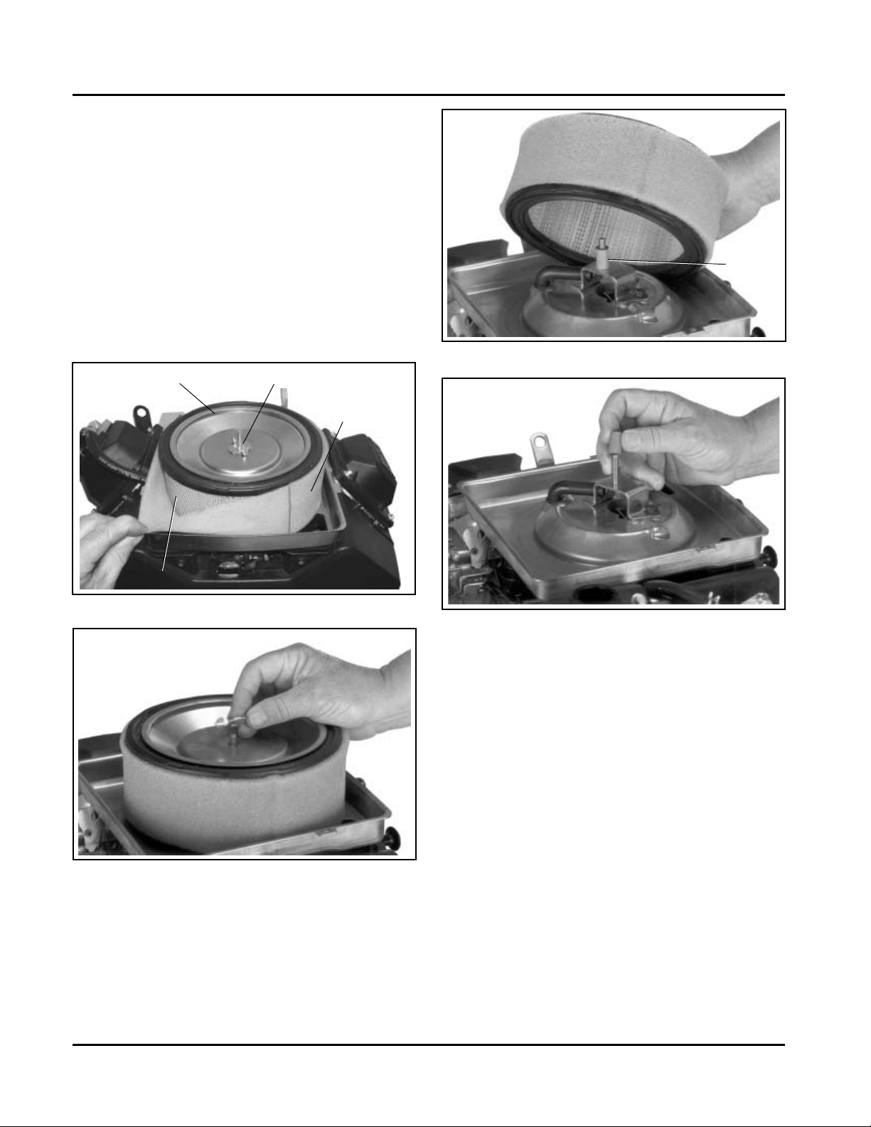
Figure 4-1. Standard Air Cleaner.
4
Figure 4-2. Removing Latch Style Cover.
Cover
Air Cleaner Element
Precleaner
Standard Air Cleaner
Service
Check the air cleaner daily or before starting the
engine. Check for and correct any buildup of dirt and
debris, along with loose or damaged components.
NOTE: Operating the engine with loose or damaged
air cleaner components could allow unfiltered
air into the engine, causing premature wear
and failure.
Figure 4-3. Removing Knob Style Cover .
Precleaner Service
If so equipped, wash and reoil the precleaner every 25
hours of operation (more often under extremely dusty
or dirty conditions).
To service the precleaner, perform the following steps:
1. Unhook the latches or loosen the retaining knob,
and remove the cover.
2. Remove the foam precleaner from the paper air
cleaner element.
4.1
Page 29
Section 4
Air Cleaner and Air Intake System
3. Wash the precleaner in warm water with
detergent. Rinse the precleaner thoroughly until
all traces of detergent are eliminated. Squeeze
out excess water (do not wring). Allow the
precleaner to air dry .
4. Saturate the precleaner with new engine oil.
Squeeze out all excess oil.
5. Reinstall the precleaner over the paper air cleaner
element.
6. Reinstall the air cleaner cover . Secure the cover
with the two latches or the retaining knob.
Element Cover
Element
Figure 4-4. Air Cleaner Components.
Wing Nut
Precleaner
Seal
Figure 4-6. Removing Elements.
Figure 4-7. Removing Rubber Seal from Bracket.
Paper Element Service (Standard Type)
Every 100 hours of operation (more often under
extremely dusty or dirty conditions), replace the paper
element. Follow these steps:
Figure 4-5. Removing Element Cover Wing Nut.
4.2
1. Unhook the latches or loosen the retaining knob,
and remove the cover.
2. Remove the wing nut, element cover, and p aper
element with precleaner (if so equipped).
3. Remove the precleaner (if so equipped) from the
paper element. Service the precleaner as
described in "Precleaner Service".
4. Do not wash the paper element or use
pressurized air, as this will damage the element.
Replace a dirty , bent, or damaged element with a
genuine Kohler element. Handle new elements
carefully; do not use if the sealing surfaces are
bent or damaged.
Page 30
Section 4
Air Cleaner and Air Intake System
5. Check the seal for any damage or deterioration.
Replace as necessary . See Figure 4-7.
6. Reinstall the seal, paper element, precleaner ,
element cover, and wing nut.
7. Reinstall the air cleaner cover and secure with the
latches or the retaining knob.
NOTE: Make sure the correct depth air cleaner
element and rubber seal are used for the
engine spec involved. Some engines use
a deeper or extra capacity air cleaner
and a longer rubber seal.
4
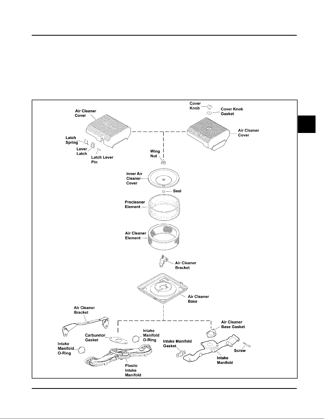
Figure 4-8. Exploded View of St andard Air Int ake System Component s.
4.3
Page 31

Section 4
Air Cleaner and Air Intake System
Figure 4-9. Bracket Retaining Screw.
Air Cleaner Element Cover and Seal - Make sure
element cover is not bent or damaged. Make sure the
wing nut and seal are in place to ensure the element is
sealed against leakage.
Air Cleaner Base - Make sure the base is secured
tightly to the carburetor and not cracked or damaged.
Breather T ube - Make sure the tube is att ached to
both the air cleaner base and the breather cover.
NOTE: Damaged, worn or loose air cleaner
components can allow unfiltered air into the
engine causing premature wear and failure.
Tighten or replace all loose or damaged
components.
Rear Mounting
Screws
Figure 4-10. Rear Mounting Screws (Used with
Plastic Intake Manifold).
Complete Disassembly and Reassembly Standard Type
If the base plate on the standard type has to be
removed, proceed as follows:
1. Remove air cleaner components as described
earlier.
2. Remove the hex. flange screws securing the
bracket and base. See Figures 4-9 and 4-10.
Remove the bracket.
3. Pinch the sealing collar on the breather hose and
push it down through the hole in the air cleaner
base. Carefully feed the upper section of the
breather tube down through the base. See Figure
4-11.
4. Remove the base and gasket.
5. Reverse the procedure to reinstall new or serviced
components. Torque screws to 9.9 N·m
(88 in. lb.).
Figure 4-11. Breather Tube.
Air Cleaner Components
Whenever the air cleaner cover is removed, or the
paper element or precleaner are serviced, check the
following:
4.4
Heavy-Duty Air Cleaner
General
The heavy-duty air cleaner consists of a cylindrical
housing, typically mounted to a bracket off the upper
valve cover screws, and connected with a formed
rubber hose to an adapter on the carburetor or throttle
body/intake manifold (EFI units). The air cleaner
housing contains a paper element and inner element,
designed for longer service intervals. The system is
CARB/EP A certified and the components should not be
altered or modified in any way .
Page 32

Figure 4-12. Heavy-Duty Air Cleaner .
T o Service
Every 250 hours of operation (more often under
extremely dusty or dirty conditions), replace the
paper element and check the inner element. Follow
these steps.
1. Unhook the two retaining clips and remove the
end cap from the air cleaner housing.
Section 4
Air Cleaner and Air Intake System
4. Do not wash the paper element and inner
element or use compressed air, this will damage
the elements. Replace dirty, bent or damaged
elements with new genuine Kohler elements as
required. Handle the new elements carefully; do
not use if the sealing surfaces are bent or
damaged.
5. Check all parts for wear, cracks, or damage.
Replace any damaged components.
6. Install the new inner element, followed by the
outer element. Slide each fully into place in the air
cleaner housing.
7. Reinstall the end cap so the dust ejector valve is
down, and secure with the two retaining clips. See
Figure 4-12.
Removal
1. Remove the upper valve cover screws on each
side, securing the main bracket, and loosen the
hose clamp on the adapter inlet, or remove the
adapter mounting screws.
4
2. Pull the air cleaner element out of the housing.
See Figure 4-13.
Inner
Element
Figure 4-13. Removing Elements.
3. After the element is removed, check the condition
of the inner element. It should be replaced
whenever it appears dirty , typically every other
time the main element is replaced. Clean the area
around the base of the inner element before
removing it, so dirt does not get into the engine.
Element
2. Lift the entire air cleaner assembly off the engine.
Disassemble or service as required.
Installation
1. Install the main mounting bracket with the center
section up and the cutout around the carburetor,
aligning the mounting holes with the four upper
valve cover holes.
2. Install and torque the four valve cover mounting
screws to 7.9 N·m (70 in. lb.).
3. Reconnect the hose to the adapter and tighten the
clamp, or install a new adapter gasket (if the
adapter was separated from the carburetor), and
torque the mounting fasteners to 7.3 N·m
(65 in. lb.).
NOTE: Adapter configurations may vary
depending on engine and application
involved. T wo adapters are shown in
Figure 4-14.
4.5
Page 33

Section 4
Air Cleaner and Air Intake System
Figure 4-14. Adapters for Heavy-Duty Air Cleaners.
Air Intake/Cooling System
To ensure proper cooling, make sure the grass screen,
cooling fan fins, and external surfaces of the engine
are kept clean at all times.
Every 100 hours of operation (more often under
extremely dusty or dirty conditions), remove the blower
housing and other cooling shrouds.*Clean the cooling
fins and external surfaces as necessary . Make sure
the cooling shrouds are reinstalled.
*Cleanout kits, Kohler Part No. 25 755 20-S (black) or
25 755 21-S (gold), are recommended to aid
inspection and cleanout of the cooling fins. See
Figure 4-15.
NOTE: Operating the engine with a blocked grass
screen, dirty or plugged cooling fins, and/or
cooling shrouds removed, will cause engine
damage due to overheating.
Figure 4-15. Cleanout Kit Installed on Blower
Housing.
4.6
Page 34

Fuel System and Governor
Section 5
Fuel System and Governor
Section 5
CH18-745
Description
The Command horizontal twins use three different
types of fuel systems; carbureted, electronic fuel
injection (EFI), or gaseous. Gaseous fuel systems can
be either liquefied petroleum gas (LPG or LP) or
natural gas (NG). Some dual-fuel engines have a
combination system, which allows the operator to
select either gasoline or LP.
This section covers the standard carbureted fuel
systems. The gaseous systems are covered in
subsection 5A and the EFI systems are covered in
subsection 5B. The governor systems used are
covered at the end of this section.
WARNING: Explosive Fuel!
Gasoline is extremely flammable and its vapors can
explode if ignited. Store gasoline only in approved
containers, in well ventilated, unoccupied buildings,
away from sparks or flames. Do not fill the fuel tank
while the engine is hot or running, since spilled fuel
could ignite if it comes in contact with hot parts or
sparks from ignition. Do not start the engine near
spilled fuel. Never use gasoline as a cleaning agent.
Fuel System Components
The typical carbureted fuel system and related
components include the following:
Fuel then enters the carburetor float bowl and is drawn
into the carburetor body . There, the fuel is mixed with
air. This fuel-air mixture is then burned in the engine
combustion chamber.
Fuel Recommendations
5
General Recommendations
Purchase gasoline in small quantities and store in
clean, approved containers. A container with a capacity
of 2 gallons or less with a pouring spout is
recommended. Such a container is easier to handle
and helps eliminate spillage during refueling.
• Do not use gasoline left over from the previous
season, to minimize gum deposits in your fuel
system and to ensure easy starting.
• Do not add oil to the gasoline.
• Do not overfill the fuel tank. Leave room for the
fuel to expand.
Fuel T y pe
For best results, use only clean, fresh, unleaded
gasoline with a pump sticker octane rating of 87 or
higher. In countries using the Research fuel rating
method, it should be 90 octane minimum.
• Fuel Tank
• Fuel Lines
• In-line Fuel Filter
• Fuel Pump
• Carburetor
Operation
The fuel from the tank is moved through the in-line
filter and fuel lines by the fuel pump. On engines not
equipped with a fuel pump, the fuel tank outlet is
located above the carburetor inlet allowing gravity to
feed fuel to the carburetor.
Unleaded gasoline is recommended as it leaves less
combustion chamber deposits and reduces harmful
exhaust emissions. Leaded gasoline is not
recommended and must not be used on EFI engines,
or on other models where exhaust emissions are
regulated.
Gasoline/Alcohol blends
Gasohol (up to 10% ethyl alcohol, 90% unleaded
gasoline by volume) is approved as a fuel for Kohler
engines. Other gasoline/alcohol blends are not
approved.
5.1
Page 35

Section 5
Fuel System and Governor
Gasoline/Ether blends
Methyl Tertiary Butyl Ether (MTBE) and unleaded
gasoline blends (up to a maximum of 15% MTBE by
volume) are approved as a fuel for Kohler engines.
Other gasoline/ether blends are not approved.
Fuel System T est s
When the engine starts hard, or turns over but will not start, it is possible that the problem is in the fuel system. To
find out if the fuel system is causing the problem, perform the following tests.
Fuel Filter
Most engines are equipped with an in-line filter.
Visually inspect the filter periodically and replace when
dirty with a genuine Kohler filter.
Troubleshooting – Fuel System Related Causes
T est Conclusion
1. Check the following:
a. Make sure the fuel tank contains clean, fresh,
proper fuel.
b. Make sure the vent in fuel tank is open.
c. Make sure the fuel valve is open.
d. Make sure vacuum and fuel lines to fuel
pump are secured and in good condition.
2. Check for fuel in the combustion chamber.
a. Disconnect and ground spark plug leads.
b. Close the choke on the carburetor.
c. Crank the engine several times.
d. Remove the spark plug and check for fuel at
the tip.
2. If there is fuel at the tip of the spark plug, fuel is
reaching the combustion chamber.
If there is no fuel at the tip of the spark plug, check
for fuel flow from the fuel tank (Test 3).
3. Check for fuel flow from the tank to the fuel pump.
a. Remove the fuel line from the inlet fitting of
fuel pump.
b. Hold the line below the bottom of the tank.
Open the shut-off valve (if so equipped) and
observe flow.
4. Check the operation of fuel pump.
a. Remove the fuel line from the inlet fitting of
carburetor.
b. Crank the engine several times and observe
flow.
3. If fuel does flow from the line, check for faulty fuel
pump (Test 4).
If fuel does not flow from the line, check the fuel
tank vent, fuel pickup screen, in-line filter, shut-of f
valve, and fuel line. Correct any observed problem
and reconnect the line.
4. If fuel does flow from the line, check for faulty
carburetor. (Refer to the "Carburetor" portions of
this section.)
If fuel does not flow from the line, check for a
clogged fuel line. If the fuel line is unobstructed,
check for overfilled crankcase and/or oil in pulse
line. If none of the checks reveal the cause of the
problem, replace the pump.
5.2
Page 36

Section 5
Fuel System and Governor
Fuel Pump
General
These engines are equipped with either a pulse or
mechanical fuel pump. See Figures 5-1 and 5-2. The
pumping action is created by either the oscillation of
positive and negative pressures within the crankcase
through a hose, or by direct lever/pump actuation off
rocker arm movement. The pumping action causes the
diaphragm on the inside of the pump to pull fuel in on
its downward stroke and to push it into the carburetor
on its upward stroke. Internal check valves prevent
fuel from going backward through the pump.
Outlet Line (to Carburetor)
Pulse Fuel
Pump
Pulse Line
Inlet Line
NOTE: On most models, the pulse line is
connected to a fitting on the crankcase,
while on early models, it is connected to
the valve cover.
4. Install the new fuel pump using the hex. flange
screws. Torque the hex. flange screws to 2.3 N·m
(20 in. lb.).
NOTE: Make sure the orientation of the new
pump is consistent with the removed
pump. Internal damage may occur if
installed incorrectly .
5. Connect the pulse line to the pulse fitting.
6. Connect the fuel lines to the inlet and outlet
fittings.
Replacing the Mechanical Pump
The mechanical pump is an integral part of the valve
cover assembly and not serviced separately . See
Figure 5-2.
1. Disconnect the fuel lines from the inlet and outlet
fittings.
5
Figure 5-1. Pulse Style Fuel Pump.
Performance
Minimum fuel delivery rate must be 7.5 L/hr. (2 gal./hr.)
with a pressure at 0.3 psi and a fuel lift of 18 in. from
carburetor inlet. A 1.3 L/hr. (0.34 gal./hr.) fuel rate must
be maintained at 5 Hz.
Fuel Pump - Replacement
Replacing the Pulse Fuel Pump
Replacement pumps are available through your source
of supply . To replace the pulse pump follow these
steps.
1. Disconnect the fuel lines from the inlet and outlet
fittings.
2. Remove the hex. flange screws securing the fuel
pump.
3. Remove the pulse line that connects the pump to
the crankcase or valve cover.
2. Follow the procedure for replacing the valve cover
(Sections 9 and 11).
3. Reconnect the fuel lines to the inlet and outlet
fittings.
Outlet Line (to
Carburetor)
Mechanical
Fuel Pump
Inlet Line
Figure 5-2. Mechanical Fuel Pump.
5.3
Page 37

Section 5
Fuel System and Governor
Carburetor
General
These engines are equipped with fixed main jet
carburetors manufactured by Keihin to Kohler
specifications. Most have automatic chokes and fuel
shut-off solenoids. Keihin carburetors with accelerator
pump features are standard on many models, and are
furnished as an option on other CH applications where
improved performance is required during periods of
rapid acceleration. Both types are almost identical
except for the accelerator pump parts shown in the
inset in Figure 5-8. Most information in the following
pertains to both type carburetors, with differences
pointed out or shown wherever pertinent.
Troubleshooting - Carburetor Related Causes
Condition
1. Engine starts hard, runs roughly or
stalls at idle speed.
2. Engine runs rich (indicated by
black, sooty exhaust smoke,
misfiring, loss of speed and power,
governor hunting, or excessive
throttle opening).
3. Engine runs lean (indicated by
misfiring, loss of speed and power,
governor hunting or excessive
throttle opening).
1. Low idle fuel mixture (some models)/speed improperly adjusted.
Adjust the low idle speed tab, then adjust the low idle fuel needle.
2a. Clogged air cleaner. Clean or replace.
b. Choke partially closed during operation. Check the choke lever/
linkage to ensure choke is operating properly .
c. Low idle fuel mixture is improperly adjusted. Adjust low idle fuel
needle (some models).
d. Float level is set too high. Separate carburetor air horn from
carburetor body , adjust float according to step s 4 and 5 on page
5.7.
e. Dirt under the fuel inlet needle. Remove needle; clean needle and
seat and blow with compressed air.
f. Bowl vent or air bleeds plugged. Remove low idle fuel adjusting
needle. Clean vent, ports, and air bleeds. Blow out all passages
with compressed air.
g. Leaky , cracked or damaged float. Submerge float to check for
leaks.
3a. Low idle fuel mixture is improperly adjusted. Adjust low idle fuel
needle (some models).
b. Float level is set too low. Sep arate carburetor air horn from
carburetor body , adjust float according to step s 4 and 5 on page
5.7.
c. Idle holes plugged; dirt in fuel delivery channels. Remove low idle
fuel adjusting needle. Clean main fuel jet and all passages; blow
out with compressed air.
WARNING: Explosive Fuel
Gasoline is extremely flammable and its vapors can
explode if ignited. Store gasoline only in approved
containers, in well ventilated, unoccupied buildings,
away from sparks or flames. Do not fill the fuel tank
while the engine is hot or running, since spilled fuel
could ignite if it comes in contact with hot parts or
sparks from ignition. Do not start the engine near
spilled fuel. Never use gasoline as a cleaning agent.
Possible Cause/Probable Remedy
4. Fuel leaks from carburetor. 4a. Float level set too high. See Remedy 2d.
b. Dirt under fuel inlet needle. See Remedy 2e.
c. Bowl vents plugged. Blow out with compressed air.
d. Carburetor bowl gasket leaks. Replace gasket.
5.4
Page 38

Section 5
Fuel System and Governor
Troubleshooting Checklist
When the engine starts hard, runs roughly or stalls at
low idle speed, check the following areas before
adjusting or disassembling the carburetor.
• Make sure the fuel tank is filled with clean, fresh
gasoline.
• Make sure the fuel tank cap vent is not blocked
and that it is operating properly .
• Make sure fuel is reaching the carburetor. This
includes checking the fuel shut-off valve, fuel tank
filter screen, in-line fuel filter, fuel lines and fuel
pump for restrictions or faulty components as
necessary.
• Make sure the air cleaner base and carburetor
are securely fastened to the engine using gaskets
in good condition.
• Make sure the air cleaner element (including
precleaner if equipped) is clean and all air cleaner
components are fastened securely .
• Make sure the ignition system, governor system,
exhaust system, and throttle and choke controls
are operating properly .
If the engine is hard-starting, runs roughly, or stalls at
low idle speed, it may be necessary to adjust or
service the carburetor.
High Altitude Operation
When operating the engine at altitudes of 1500 m
(5000 ft.) and above, the fuel mixture tends to get
over-rich. This can cause conditions such as black,
sooty exhaust smoke, misfiring, loss of speed and
power, poor fuel economy, and poor or slow governor
response.
To compensate for the effects of high altitude, special
high altitude jet kits are available. The kits include a
new main jet, slow jet (where applicable), necessary
gaskets and O-Rings. Refer to the parts manual for the
correct kit number.
When current is removed the pin extends blocking the
main fuel jet and preventing fuel from entering the
carburetor.
Fuel Shut-off Solenoid
5
Figure 5-3. Fuel Shut-off Solenoid.
Below is a simple test, made with the engine off, that
can determine if the solenoid is functioning properly:
1. Shut off fuel and remove the solenoid from the
carburetor. When the solenoid is loosened and
removed, gas will leak out of the carburetor. Have
a container ready to catch the fuel.
2. Wipe the tip of the solenoid with a shop towel or
blow it off with compressed air , to remove any
remaining fuel. Take the solenoid to a location
with good ventilation and no fuel vapors present.
You will also need a 12 volt power source that can
be switched on and off.
3. Be sure the power source is switched “off”.
Connect the positive power source lead to the red
lead of the solenoid. Connect the negative power
source lead to the solenoid bracket.
4. Turn the power source “on” and observe the pin in
the center of the solenoid. The pin should retract
with the power “on” and return to its original
position with the power off. Test several times to
verify operation.
Fuel Shut-off Solenoid
Most carburetors are equipped with a fuel shut-off
solenoid. The solenoid is attached in place of the fixed
main jet screw on the flywheel side of the carburetor.
See Figure 5-3. The solenoid has a spring-loaded pin
that retracts when 12 volts is applied to the lead,
allowing fuel flow through the main jet.
5.5
Page 39

Section 5
Fuel System and Governor
Carburetor Adjustments
General
In compliance with government emission standards,
the carburetor is calibrated to deliver the correct air-tofuel mixture to the engine under all operating
conditions. The high-speed mixture is preset and
cannot be adjusted. Pre-compliance carburetors
contain a low idle fuel adjusting needle, on “certified”
compliance carburetors, both the low and high speed
mixture circuits are pre-established and cannot be
adjusted. The low idle speed (RPM) is the only
adjustment available. See Figures 5-4 and 5-5.
Low Idle Speed
Adjustment
Main Jet
Location
Figure 5-4. Pre-Compliance Carburetor with Low
Idle Adjustment.
Low Idle
Speed
Adjustment
Figure 5-5. “Certified” Compliance Carburetor.
Low Idle Fuel
Adjusting Needle
Fuel Shut-Off
Solenoid (Main
Jet Location)
1. With the engine stopped, turn the low idle fuel
adjusting needle in clockwise until it bottoms
lightly.
NOTE: The tip of the idle fuel adjusting needle is
tapered to critical dimensions. Damage
to the needle and the seat in the
carburetor body will result if the needle is
forced.
2. Now turn the adjusting needle out
counterclockwise 1-1/2 turns.
3. Start the engine and run at half throttle for 5 to 10
minutes to warm up. The engine must be warm
before making final settings. Check that the
throttle and choke plates can fully open.
NOTE: The carburetor has a self-relieving
choke. Choke plate and shaft assembly
is spring loaded. Check to make sure
plate moves freely and is not binding and
affecting idle fuel delivery .
4. Place the throttle control into the “idle” or “slow”
position. Turn the low idle speed adjusting screw
in or out to obtain a low idle speed of 1200 RPM
(± 75 RPM). Check the speed using a tachometer .
NOTE: The actual low idle speed depends on
the application. Refer to the equipment
manufacturer’s recommendations. The
low idle speed for basic engines is 1200
RPM. To ensure best results when
setting the low idle fuel needle, the low
idle speed should be 1200 RPM (± 75
RPM).
5. Turn the low idle fuel adjusting needle in (slowly)
until engine speed decreases and then back out
approximately 3/4 turn to obtain the best low
speed performance.
6. Recheck the idle speed using a tachometer and
readjust the speed as necessary .
NOTE: Carburetor adjustments should be made only
after the engine has warmed up.
Adjusting Low Idle Speed and Fuel (Some Models)
To adjust the carburetor idle speed, see Figure 5-4 and
follow these steps.
5.6
Float
It is not necessary to remove the carburetor from the
engine to check and adjust the float.
1. Remove the air cleaner and breather hose. Refer
to Section 9 – ‘‘Disassembly”.
Page 40

2. Disconnect the fuel line from the carburetor. See
Figure 5-6.
3. Clean dirt and debris from exterior of carburetor.
4. Remove the four screws holding the two
carburetor halves together. Carefully lif t the upper
body off the carburetor body and disconnect
choke linkage.
Section 5
Fuel System and Governor
Tab
Float
Screws
Fuel Line
Figure 5-6. Carburetor Detail.
5. Hold the carburetor upper body so that the float
assembly hangs vertically and rests lightly against
the fuel inlet needle. The fuel inlet needle should
be fully seated, but the needle tip should not be
depressed. See Figure 5-7.
NOTE: The fuel inlet needle tip is spring loaded.
Make sure the float assembly rests
against the fuel inlet needle without
depressing the tip.
6. The correct float height adjustment is 22 mm
(0.86 in.), measured from the float bottom to the
air horn casting. Adjust the float height by
carefully bending the tab.
Figure 5-7. Carburetor Float Adjustment.
8. Once the proper float height is obtained, carefully
lower the carburetor air horn assembly onto the
carburetor body , connecting the choke linkage.
Install the four screws. Torque the screws to
1.7 N·m (15 in. lb.). See Figure 5-6.
9. Connect the fuel line.
10. Inst all the breather hose and air cleaner
assembly , following the step s in Section 11 –
‘‘Reassembly”.
Disassembly
Disassemble the carburetor using the following steps.
See Figure 5-8.
1. Remove the air cleaner, breather hose and
carburetor. Refer to Section 9 – “Disassembly”.
2. Remove the four screws and carefully separate
the air horn assembly from the carburetor body .
3. Loosen the screw securing the float assembly to
the air horn and remove the float, float shaft and
fuel inlet needle.
5
NOTE: Be sure to measure from the casting
surface, not the rubber gasket surface.
7. If proper float height adjustment cannot be
achieved, check to see if the fuel inlet needle is
dirty , obstructed or worn. Remove the brass
screw and float assembly to remove the fuel inlet
needle.
4. Remove the slow jet from the carburetor body .
NOTE: The main jet is a fixed jet and can be
removed if required. Fixed jets for high
altitude are available.
5. Remove the black cap on the end of the choke
shaft only if it is necessary to inspect and clean
the shaft spring.
6. Remove the low idle speed adjusting screw and
spring from the carburetor body .
5.7
Page 41

Section 5
Fuel System and Governor
7. In order to clean the ‘‘off-idle’’ vent ports and bowl
vent thoroughly , use a good carburetor solvent
(like Gumout™). Blow clean compressed air
through the idle adjusting needle hole. Be careful
to use a suitable shop rag to prevent debris from
hitting someone.
8. Remove the preformed rubber gasket only if it is
to be replaced. If it is removed for any reason,
replace it.
Inspection/Repair
Carefully inspect all components and replace those
that are worn or damaged.
• Inspect the carburetor body for cracks, holes and
other wear or damage.
• Inspect the float for cracks, holes, and missing or
damaged float tabs. Check the float hinge and
shaft for wear or damage.
• Inspect the fuel inlet needle and seat for wear or
damage.
• Inspect the tip of the low idle fuel adjusting needle
for wear or grooves.
• The choke plate is spring loaded. Check to make
sure it moves freely on the shaft.
NOTE: The choke and throttle plate assemblies
are staked and matched to the shafts at
the factory . They are not serviceable
items.
Always use new gaskets when servicing or reinstalling
carburetors. Repair kits are available which include
new gaskets and other components. These kit s are
described on the next page.
5.8
Page 42

Section 5
Fuel System and Governor
1. Carburetor Upper Body (Choke)
2. Self-relieving Choke
2
4
5
6
7
9
1
3
15
8
3. Body Gasket (Formed Rubber)
4. Slow Speed Jet
5. Inlet Needle Valve
6. Clip
7. Float Pin
8. Float Assembly (Kit)
9. Carburetor Lower Body (Throttle)
10. Main Jet
11. Idle Fuel Adjusting Needle (some models)
12. Solenoid Seat
13. Fuel Shut-off Solenoid (Kit)
14. Idle S peed Adjusting Screw
15. Jet (Accelerator Pump Carburetor only)
16. Accelerator Pump Cover
17. Diaphragm
18. Diaphragm S pring
19. O-Ring
20. Rubber Boot
21. Bushing
22. Return S pring
5
10
11
14
12
13
Figure 5-8. Carburetor – Exploded View.
Components such as the throttle and choke shaft
assemblies, throttle plate, choke plate, low idle fuel
needle, and others, are available separately .
Always refer to the Parts Manual for the engine being
serviced, to ensure the correct repair kits and
replacement parts are ordered. Service/repair kits
available for the carburetor and affiliated components
are:
19
17
18
19
16
21
20
Carburetor Repair Kit
Float Kit
High Altitude Kit (1525-3048 m/5,000-10,000 ft)
High Altitude Kit (over 3048 m/10,000 ft)
Solenoid Assembly Kit
Accelerator Pump Seal and Bushing Kit
Accelerator Pump Diaphragm Kit
Choke Repair Kit
22
Accelerator Pump V ersion Only
5.9
Page 43

Section 5
Fuel System and Governor
Reassembly
Reassemble the carburetor using the following steps.
See Figure 5-9.
1. Assemble the fuel inlet needle to the float tab.
Install the float, float shaft and inlet needle to the
air horn. Tighten the screw. Check float height
using the procedure found previously in the
‘‘Adjustments’’ subsection.
2. Install the slow jet with the stepped end toward
the bottom of the carburetor. Make sure jet is fully
seated.
3. Install the low idle adjusting needle and spring.
4. Assemble the upper body onto the lower
carburetor body using the four screws. Torque the
screws to 1.7 N·m (15 in. lb.).
5. Install the carburetor on the engine following the
procedures in Section 1 1 – ‘‘Reassembly.’’
Governor
General
The governor is designed to hold the engine speed
constant under changing load conditions. Most
engines are equipped with a centrifugal flyweight
mechanical governor. Some engines utilize an optional
electronic governor, which is shown and covered on
page 5.12 and 5.13. The governor gear/flyweight
mechanism of the mechanical governor is mounted
inside the crankcase and is driven off the gear on the
camshaft. This governor design works as follows:
• Centrifugal force acting on the rotating governor
gear assembly causes the flyweights to move
outward as speed increases. Governor spring
tension moves them inward as speed decreases.
Governor Spring
Cross Shaft
Governor Arm
Hex. Nut
Throttle
Linkage
Figure 5-9. Governor Linkage.
• As the flyweights move outward, they cause the
regulating pin to move outward.
• The regulating pin contacts the tab on the cross
shaft causing the shaft to rotate.
• One end of the cross shaft protrudes through the
crankcase. The rotating action of the cross shaft
is transmitted to the throttle lever of the carburetor
through the external throttle linkage. See Figure
5-9.
• When the engine is at rest, and the throttle is in
the “fast” position, the tension of the governor
spring holds the throttle plate open. When the
engine is operating, the governor gear assembly
is rotating. The force applied by the regulating pin
against the cross shaft tends to close the throttle
plate. The governor spring tension and the force
applied by the regulating pin balance each other
during operation, to maintain engine speed.
• When load is applied and the engine speed and
governor gear speed decreases, the governor
spring tension moves the governor arm to open
the throttle plate wider. This allows more fuel into
the engine, increasing the engine speed. As the
speed reaches the governed setting, the governor
spring tension and the force applied by the
regulating pin will again offset each other to hold a
steady engine speed.
5.10
Adjustments
NOTE: Do not tamper with the governor setting.
Overspeed is hazardous and could cause
personal injury .
Page 44

General
The governed speed setting is determined by the
position of the throttle control. It can be variable or
constant, depending on the engine application.
Initial Adjustment
NOTE: EFI engines require a special initial
adjustment procedure, which is covered in
subsection 5B. Refer to “Initial Governor
Adjustment” in that section for setting the
governor on EFI-equipped engines.
Procedure – Carburetor Equipped Engines
Make this adjustment whenever the governor arm is
loosened or removed from the cross shaft. See Figure
5-9 and adjust as follows:
1. Make sure the throttle linkage is connected to the
governor arm and the throttle lever on the
carburetor.
Section 5
Fuel System and Governor
Figure 5-10. Governor Sensitivity Adjustments.
High Speed (RPM) Adjustment (Refer to Figure 5-11.)
1. With the engine running, move the throttle control
to fast. Use a tachometer to check the RPM
speed.
5
2. Loosen the hex. nut holding the governor lever to
the cross shaft.
3. Move the governor lever toward the carburetor as
far as it will move (wide open throttle) and hold in
this position.
4. Insert a nail into the hole on the cross shaft and
rotate the shaft counterclockwise as far as it will
turn, then tighten hex. nut securely .
Sensitivity Adjustment
Governor sensitivity is adjusted by repositioning the
governor spring in the holes of the governor lever. If
speed surging occurs with a change in engine load,
the governor is set too sensitive. If a big drop in speed
occurs when normal load is applied, the governor
should be set for greater sensitivity . See Figure 5-10
and adjust as follows:
1. To increase the sensitivity, move the spring closer
to the governor cross shaft.
2. To decrease the sensitivity, move the spring away
from the governor cross shaft.
2. Loosen the lock nut on high speed adjusting screw.
Turn the screw outward to decrease, or inward to
increase the RPM speed. Check RPM with a
tachometer.
3. When the desired RPM speed is obtained,
retighten the lock nut.
NOTE: When the throttle and choke control cables are
routed side-by-side, especially under a single
clamp, there must be a small gap between the
cables to prevent internal binding. Af ter the
high-speed setting has been completed, check
that there is a gap of at least 0.5 mm
(0.020 in.) between the control cables.
5.11
Page 45

Section 5
Fuel System and Governor
Left Side Pull
Choke Control Cable
Throttle
Control
Cable
Kill Switch Adjusting Screw
Dual Control High
Speed Lever Stop Screw
"Do Not Remove"
Figure 5-11. Governor Control Connections.
Kill Switch
High Speed
Adjusting
Screw
Throttle Control Lever #2
Choke Control Lever #1
High Speed
Control Lever
Choke Linkage
Z Bend
Throttle Control Cable
Choke
Control
Cable
Right Side Pull
Electronic Governor
General
The electronic governor regulates engine speed at
varying loads. It consists of a governor control unit,
digital linear actuator and linkage.
5
4
3
2
1
Figure 5-12. Electronic Governor Assembly .
1. Digital Linear Actuator
2. Throttle Linkage
3. Linkage Spring
4. Choke Linkage
5. Throttle Lever Adapter
Governor Control Unit
Figure 5-13. Electronic Governor Assembly.
Digital Linear Actuator (DLA)
Energizing the bi-directional digital linear actuator coils
in the proper sequence, causes the threaded shaft to
move out of, or back into the rotor, in precise linear
increments. When power is removed, the actuator
shaft remains in position. The DLA must initialize (fully
extend) to move the throttle plate to the closed
position, and partially open for starting. Correct
adjustment of the DLA is critical to achieve the full
range of throttle plate movement. See Adjustment
Procedure.
5.12
Page 46

Section 5
Fuel System and Governor
Governor Control Unit (GCU) senses engine speed by
pulse voltage inputs from the ignition modules. The
GCU regulates the engine speed by variable input
voltage from a customer-supplied potentiometer or a
single pole, single throw (SPST) switch.
Potentiometer Specifications:
Wiper V olt age
0-1
1-9
9-16
SPST Switch Specifications:
Switch Position
Open
Closed
GCU Safety Features
In the event of an engine overspeed condition, the
GCU will shut down the engine by grounding the
ignition modules.
The GCU will shut down the engine by grounding the
ignition when power to the GCU is lost.
Engine Speed (RPM)
1860 low speed endpoint
variable speed endpoint
3600 high speed endpoint
Engine Speed (RPM)
1860 low speed endpoint
3600 high speed endpoint
Adjustment Procedure
The DLA must be in the fully retracted position during
assembly . The full range of throttle plate movement will
not be achieved if the DLA is p artially extended when
assembled. Loosen the two DLA mounting plate
screws located on the top of the actuator plate. With
the throttle linkage centered in the U-Clip at the end of
the DLA shaf t, slide the DLA bracket assembly back
until the throttle plate is fully open. Torque the
mounting plate screws to 2.5 N·m (22 in. lb.).
Troubleshooting Procedure
Engine starts, but will not continue to run
1. Check the linkage connection between the DLA
and throttle plate.
2. Verify the DLA initializes when power is supplied
(key switch in the start or run position).
3. Test the potentiometer wiper output voltage (if
equipped).
4. Test the SPST switch (if equipped).
5. Check the wire harness and connections.
5
Linkage
The throttle linkage spring will fully open the throttle
plate if the linkage becomes detached from the DLA.
This will create an overspeed condition causing the
engine to shut down. The DLA shaft will have to be
manually screwed back into the body , and then
retracted before reassembling the linkage.
Engine does not run at the expected speed
1. Check to see that the throttle linkage and DLA
have full range of motion having no mechanical
interference.
2. Test the potentiometer wiper voltage (if equipped).
3. Test the SPST switch (if equipped).
5.13
Page 47

Section 5
Fuel System and Governor
5.14
Page 48

Section 5A
LPG Fuel Systems
CH18-740
Section 5A
LPG Fuel Systems
WARNING: Explosive Fuel!
LPG is extremely flammable, is heavier than air, and tends to settle in low areas where a sp ark or flame could
ignite the gas. Do not start or operate this engine in a poorly ventilated area where leaking gas could accumulate
and endanger the safety of persons in the area.
Proper service and repair of LPG fuel systems requires qualified technicians and special equipment.
Many states require special licensing or certification for LPG repair shops and/or technicians. Check state
and local regulations before attempting any adjustment, service, or repair of the LPG system or
components. Faulty repairs by unqualified or underqualified personnel can have very serious
ramifications. The information in this segment is for the exclusive use of qualified LPG service providers.
5A
LPG Fuel System Components
The typical “liquid withdrawal” LPG fuel system consists of the following components:
• LPG Fuel Tank (Liquid Withdrawal)
• Electric Lock-Off/Filter Assembly
• Vaporizer
• LPG Regulator (Combination Primary/Secondary/Vacuum Lock-Off)
• LPG Carburetor
• High Pressure Fuel Line(s)
• Vacuum Line
Fuel Line
Vaporizer
Vacuum Line
Figure 5A-1.
Lock-Off/Filter
Assembly
LPG Regulator
5A.1
Page 49

Section 5A
LPG Fuel Systems
Operation
In a liquid withdrawal system, the Liquefied Petroleum
Gas (LPG) is released from the bottom of the supply
tank under high pressure. Upon opening the shut-off
valve on the tank, liquid fuel travels out through the
high pressure line to the electric lock-off/filter
assembly . The lock-off opens internally when the key
switch is turned “on,” permitting filtered fuel to flow to
the vaporizer. The vaporizer is mounted in the flow of
the discharged cooling air. It absorbs heat from the
cooling air and transfers it to the fuel, changing the
liquefied petroleum to a vapor or gaseous state, while
partially stepping down the fuel pressure. The gas/
vapor flows under this decreased pressure to the
regulator where it is further reduced to a usable,
regulated pressure. The regulator, activated by int ake
manifold vacuum, controls fuel flow to the carburetor.
In the venturi of the carburetor, the fuel vapor is mixed
with incoming air from the air cleaner in the correct
ratio for efficient combustion.
Troubleshooting Checklist
If the engine starts hard, runs roughly, or stalls, check
the following areas.
• Make sure the LPG fuel tank is filled and shut-off
valve is fully opened.
• Make sure fuel is reaching the carburetor.
• Make sure the air cleaner element and precleaner
are clean and all components are fastened
securely.
• Make sure the ignition, governor, exhaust, throttle,
and choke control systems are all operating
properly.
• Check compression.
If engine continues to start hard, run roughly, or stall
after these checks have been made, use the following
troubleshooting guide.
Engine cranks but will not start
1. LPG fuel tank closed, low, or empty.
2. Lock-off not opening electrically , preventing fuel
flow to vaporizer.
3. Fuel filter (located inside lock-off) dirty or blocked.
4. Insufficient vacuum signal, regulator not opening.
a. V acuum line between carburetor and regulator
cracked, leaking, kinked, or pinched.
b. Carburetor loose.
c. Intake manifold loose or leaking.
d. Excessive internal engine wear.
5. Faulty regulator.
a. Primary valve not opening.
b. Diaphragm spring adjustment incorrect.
c. Idle adjustment screw incorrectly set.
d. V ent(s) blocked/restricted.
6. Restricted/blocked fuel line.
7. Blocked carburetor fuel circuit.
8. Loose/leaking fuel enrichment hose (Impco
carburetor system).
Hard starting, runs roughly, or stalls at idle speed
1. LPG fuel tank low.
2. V acuum line between carburetor and regulator
pinched, cracked, or leaking.
3. Carburetor idle speed set too low (should be at
least 1200 RPM).
4. Carburetor idle circuit restricted.
5. Dirty/restricted air cleaner.
6. Dirty/restricted lock-off filter .
7. Frozen/malfunctioning regulator. Check/adjust
primary pressure.
8. Excessive external load on engine.
9. Excessive internal wear.
10. Loose/leaking fuel enrichment hose (Impco
carburetor system).
Irregular or inconsistent idle
1. Improper operation/adjustment of regulator, idle
adjustment screw, throttle opening, and/or engine
governor .
2. Secondary valve in regulator not closing. Readjust
idle screw (couterclockwise) so valve can close
fully against seat.
3. Loose/leaking vacuum line.
4. Loose carburetor mounting and/or line
connections.
5. Damaged diaphragm(s) within regulator.
6. Debris in regulator. Flush debris from drain plug
or remove regulator from system, disassemble
body and remove debris.
7. Dirt or debris in carburetor. Remove carburetor,
disassemble and clean/service as required. If
venturi (Impco carburetor) removal is performed,
mark its orientation to the carburetor body for
proper reinstallation.
8. Loose/leaking fuel enrichment hose (Impco
carburetor system).
5A.2
Page 50

Section 5A
LPG Fuel Systems
Engine stalls during operation
1. No fuel.
2. Faulty lock-off or blocked filter .
3. Improper governor setting.
4. Damaged diaphragms within regulator.
5. V acuum line leaking, loose, or pinched.
6. Restricted fuel line.
7. Loose/leaking fuel enrichment hose (Impco
carburetor system).
Low power
1. Air cleaner or exhaust system dirty/restricted.
2. Low fuel.
3. Rich gas condition (flooding) through regulator.
a. Dirty/restricted valves in regulator.
b. Damaged primary diaphragm in regulator.
4. No fuel.
a. Electric lock-off not opening, filter blocked, or
restriction within fuel line.
b. Leaking, loose, or cracked vacuum line from
carburetor to regulator.
c. Leaking, or loose intake system components.
d. Regulator primary valve not opening.
e. Secondary , or vacuum lock-of f diaphragm
within regulator leaking.
f. Low pressure rubber hose kinked.
g. Frozen regulator.
5. Improper ignition timing.
6. Loose/incorrect throttle lever/clamp bracket
positioning.
7. Loose or incorrectly positioned high speed throttle
plate stop.
Engine runs lean
1. Electrical problem causing intermittent lock-off
operation, or lock-off is faulty.
2. Filter in lock-off dirty or restricted.
3. Restriction in fuel system.
4. Idle holes plugged; dirt in fuel delivery channels.
5. Carburetor fuel circuit restriction.
6. Loose/leaking fuel enrichment hose (Impco
carburetor system).
LPG Carburetor Adjustment s
General
The LPG carburetor and regulator are designed to
deliver the correct fuel-to-air mixture to the engine
under all operating conditions. The high and low idle
fuel mixture settings are preset at the factory , and
cannot be adjusted. These engines are equipped with
an Impco or Nikki carburetor. See Figure 5A-2 and
5A-3. Although both carburetors function similarly,
each is unique and should not be interchanged.
Load Block Assembly
Fuel Enrichment
Hose
Venturi
Retaining
Screw
Fuel Inlet
Figure 5A-2. Impco Carburetor.
Choke Plate/Shaft Assembly
Rear Plug
with Sealing
Washer
Fuel Inlet
Plastic Bushing
Figure 5A-3. Nikki Carburetor.
Idle Speed
Adjusting Screw
Transfer
Chamber
Cover
Vacuum Port
Idle Speed
Adjusting Screw
5A
High fuel consumption
1. Fuel leak. Check lines, connections, and system
components for leaks with soapy water . Fix any
leaks immediately .
2. Incorrectly set regulator, or leakage from valves in
regulator. Readjust, service, or replace regulator
as required.
3. Dirty air cleaner or precleaner.
4. Choke plate in carburetor not opening completely .
Impco carburetors also incorporate the use of an
external ‘‘Load Block’’ assembly, which controls the
final fuel flow to the carburetor for all throttle positions
except idle. See Figure 5A-2. Calibrated and flowmatched to the carburetor, it functions similarly to
preset fuel mixture settings in other carburetors. The
load block assembly is not available separately , nor is
any internal servicing permitted or possible. If a
problem is encountered and determined to be caused
by the load block, the carburetor should be replaced.
5A.3
Page 51

Section 5A
LPG Fuel Systems
High Altitude Operation
The standard carburetor calibrations will provide
proper operation up to altitudes of 1500 m (5000 ft.).
No internal changes are necessary or available for
either carburetor.
NOTE: Carburetor adjustments should be made only
after the engine has warmed up.
Idle Speed Adjustment
1. St art the engine and run at half throttle for 5 to 10
minutes. Check that the throttle and choke (Nikki
carburetor) plates can open fully .
2. Place the throttle control into the “idle” or “slow”
position. Turn the low idle speed adjusting screw
(See Figure 5A-2 or 5A-3) in or out, to obtain a
low idle speed of 1200 RPM (± 75 RPM), or set to
application specifications. Check the speed using
a tachometer .
NOTE: The actual low idle speed (RPM) depends on
the application. Refer to the equipment
manufacturer’s recommendations. The low
idle speed for basic engines is 1200 RPM.
Impco Carburetor
1. Turn off fuel supply at t ank.
2. Remove the air cleaner, breather hose, fuel line,
vacuum hose, choke, and throttle linkages.
Remove the mounting hardware, carburetor, and
gaskets from the engine. Discard the gaskets.
3. The carburetor venturi may be removed for
inspection and appropriate cleaning.
a. Remove the four screws securing the air
cleaner adapter and gasket to the carburetor.
See Figure 5A-4.
LPG Fuel System Component Service
LPG Carburetor - Cleaning
The carburetor may be cleaned if necessary . Removal
from the engine and limited disassembly will aid in
cleaning.
NOTE: Impco Carburetor: Do not loosen or alter the
mounted position of the clamping brackets
and/or stop collar on the throttle shaft. Each is
preset, in correlation to a specific position of
the throttle plate (shaft), or acts as a stop.
None of these attached components,
including the throttle plate or shaft, requires
disassembly or removal for any carburetor
servicing. All the component s on the throttle
shaft should be left intact. If the settings of
any one of these is inadvertently loosened or
altered, each must be checked/reset, or
performance and operation will be affected.
Refer to the procedure included in the
reassembly/installation sequence to check or
reset.
Figure 5A-4.
b. Important: Mark a small line on the outer
edge of the venturi for proper orientation and
reinstallation later .
c. Loosen the venturi retaining screw on the side
of the carburetor body and lift out the
venturi. See Figure 5A-5.
5A.4
Figure 5A-5.
Page 52

Section 5A
LPG Fuel Systems
4. Inspect the overall condition of the fuel
enrichment hose attached to the carburetor . It
must be free of cracks, deterioration, and
damage. Disconnect the fuel enrichment hose
from the carburetor fittings to clean or check
condition as required. See Figure 5A-6. Replace
with a new Kohler high pressure hose (LP rated) if
the condition is questionable in any way . Secure
new hose using new clamps.
Figure 5A-6.
Nikki Carburetor
1. Turn off fuel supply at t ank.
2. Remove the air cleaner, breather hose, fuel line,
vacuum hose, choke, and throttle linkages.
Remove the nuts, carburetor , and gasket s from
the engine. Discard the gaskets.
3. Remove the fuel transfer chamber cover by
removing the three screws. See Figure 5A-3.
Carefully remove the cover and gasket. Discard
the gasket.
4. The main jet is fixed and nonadjustable, but may
be accessed for cleaning by removing the rear
plug and sealing washer. Discard the washer.
5. In order to clean the off-idle transfer passages
and carburetor thoroughly , use a good carburetor
cleaner and follow the manufacturer's
instructions. Blow clean, compressed air through
the passages and make sure all are open before
reassembling. Do not use wire or metal objects to
clean passages or carburetor body .
5A
5. Clean all parts as required, use a good carburetor
cleaner, following the manufacturer's instructions.
Blow clean, compressed air through all the
passages. Do not poke or probe into the load
block assembly as damage can be done, resulting
in serious operational problems. See Figure 5A-7.
Figure 5A-7.
LPG Carburetor - Inspection
1. Inspect the carburetor body and removable
venturi (Impco carburetor) for cracks, holes, and
other wear or damage.
2. Check the choke shaft (Nikki carburetor only) and
the throttle shaft for wear and free movement.
NOTE: Do not attempt to disassemble or
remove either shaft from the carburetor
body, including the mounted clamp
brackets on Impco style carburetors. The
screws, attaching the choke and throttle
plate to their respective shafts are staked
or bonded to prevent loosening. The
plate(s) and shaft(s) are not available
separately . If detrimental wear or
damage is found in any of the parts, the
carburetor should be replaced.
5A.5
Page 53

Section 5A
LPG Fuel Systems
LPG Carburetor - Reassembly
Impco Carburetor
1. Slide the venturi into the carburetor body , aligning
the position mark made prior to removal. Correctly
installed, the discharge holes should not be visible
from the top.
2. Secure with the venturi retaining screw . Torque
the screw to 4.0 N·m (36 in. lb.).
3. Install a new adapter gasket and mount the air
cleaner adapter onto the carburetor with the four
screws. Torque the screws to 4.0 N·m (36 in. lb.).
4. Install a new carburetor gasket onto the intake
manifold adapter, followed by the carburetor.
Install and finger tighten the mounting fasteners.
5. Connect the ‘‘Z’’ end of the throttle linkage and the
dampening spring to the throttle clamp bracket on
the throttle shaft. Attach the opposite end of
linkage and spring to the governor lever.
NOTE: The clamp brackets and stop collar
mounted on the throttle shaft should still
be in their original positions (See Figure
5A-2), and not require any readjustment/
resetting. Continue with steps 6 and 7. If
the mounted position of any one of these
was affected or changed, it will be
necessary to check and reset the
position of each before proceeding.
Follow the complete instructions listed
after step 7, then continue with steps 6
and 7.
Idle Speed Clamp Bracket Position
1. Counting the number of turns, back the idle speed
adjustment screw off (counterclockwise), so only
1 to 1 1/2 of the threads are visible. See Figure
5A-8.
Idle Speed
Clamp
Bracket
Mounting
Screw
Figure 5A-8. Backing Off Idle Speed Screw.
2. Loosen the clamp bracket mounting screw, and
pivot the throttle shaft to fully close the throttle
plate. See Figure 5A-9.
6. Manually move the governor lever toward the
carburetor as far as it will go.
7. Check that the throttle plate is now fully open or
reposition the carburetor slightly on the mounting
screws so it is fully open. Torque the mounting
screws to 9.9 N·m (88 in. lb.).
Instructions for Checking/Positioning the Clamp
Brackets Mounted on the Throttle Shaft
Use only if the position or mounting of the clamp
bracket(s) has been disturbed. Figures show the
carburetor removed from the engine for clarity .
5A.6
Figure 5A-9. Closing Throttle Plate.
3. Hold the throttle plate closed and rotate the clamp
bracket until the end of the screw contacts the
stop. Insert a 0.025 mm (0.001 in.) feeler gauge
between the carburetor housing and the side of
the clamp bracket to set the endplay , then tighten
the mounting screw securely . See Figure 5A-10.
Page 54

Figure 5A-10. Tightening Idle Speed Clamp
Mounting Screw.
4. Reset the idle speed adjustment screw back to
the original position.
High Speed/Stop Collar Position
1. Make sure the idle speed clamp position has
already been checked or properly set.
Section 5A
LPG Fuel Systems
3. Insert a 0.025 mm (0.001 in.) feeler gauge
between the side of the stop collar and the
carburetor housing, then check or set the position
of the stop collar. The head of the mounting screw
must be in contact with the carburetor boss from
the back (hose/fitting) side, preventing any further
rotation over center. Set or adjust the stop collar
as required. See Figure 5A-12.
High Speed Stop
Collar
5A
Figure 5A-12. Adjusting/Setting Stop Collar .
2. Rotate and hold the throttle shaft so the throttle
plate is fully open/perfectly vertical. See Figure
5A-11.
High Speed Stop
Collar
Figure 5A-11. Full Throttle Position.
4. Tighten the screw securely.
NOTE: After the idle speed clamp bracket and the
high speed stop collar positions have been
set, check that the throttle shaft pivots freely
without binding or restriction.
Throttle Linkage Clamp Bracket Position
Carburetor must be assembled to engine with linkage
attached to set this position.
1. The throttle linkage clamp bracket should be
positioned as shown in Figure 5A-13 on the idle
speed clamp bracket side of the throttle shaft.
Throttle
Linkage
Clamp Bracket
Figure 5A-13. Throttle Linkage Clamp Bracket
Position.
5A.7
Page 55

Section 5A
LPG Fuel Systems
2. Manually move the governor lever, with the throttle
linkage connected, toward the carburetor as far as
it will go. Hold it in this position.
3. Looking down the throat of the carburetor, check
that the throttle plate is in the full throttle position
and that the head of the high speed collar stop
screw is in contact with the carburetor boss. If not,
loosen the carburetor mounting screws and
reposition the carburetor slightly . Torque the
carburetor mounting screws to 9.9 N·m (88 in. lb.).
NOTE: If additional adjustment is required, loosen
the throttle linkage clamp bracket
mounting screw, set the throttle shaf t to
the full throttle position against the head
of the stop screw, and retighten the clamp
mounting screw securely . See Figure
5A-14.
7. Check to be sure all system connections are tight.
8. Reset idle RPM and recheck high idle (governed
speed) after starting and allowing sufficient
warm-up time.
Electric Lock-Off/Filter Assembly - Functional Test
The electric lock-off can be easily tested to verify that it
is functional. Remove it from the system for testing.
Using a 12 volt power supply or battery , connect one
wire lead to the positive (+) lead of power supply , and
touch remaining wire lead to negative (-) lead of power
supply . When connection is made, an audible “click”
should be heard indicating the opening of the lock-off.
While energized, blow compressed air through it to
determine if it is blocked or restricted.
Figure 5A-14. Tightening Throttle Linkage Clamp
Bracket.
Nikki Carburetor
1. Reinstall the rear plug with a new sealing washer .
Tighten the plug securely.
2. Reinstall fuel transfer chamber cover with a new
gasket. Secure with the three screws.
3. Install new carburetor mounting gasket on
manifold studs, followed by the carburetor and
new air cleaner base gasket.
4. Reconnect the throttle and choke linkages, and
the fuel and vacuum lines.
5. Reinstall the air cleaner base and breather tube.
Secure base with two mounting nuts. Torque nuts
to 9.9 N·m (88 in. lb.). Install the rest of the air
cleaner system.
Figure 5A-15.
Figure 5A-16.
Electric Lock-Off/Filter Assembly - Filter Service
The filter inside the lock-off assembly should be
replaced every 500 hours of operation, or if it
becomes blocked or restricted. Cleaning of the filter
element is not recommended. Order a replacement
filter element by the appropriate Kohler part number .
5A.8
Page 56

V aporizer Assembly
The outer surface of the vaporizer should be kept free
of dirt and debris accumulation, which will cause a loss
of vaporization efficiency . V isual inspection and
necessary cleaning should be performed on a regular
basis, more frequently under dusty or dirty conditions.
The vaporizer should be disassembled, cleaned, and
serviced using a rebuild kit every 1500 hours or if a
problem is encountered.
Section 5A
LPG Fuel Systems
Figure 5A-18. Impco (Beam) Regulator.
5A
Figure 5A-17.
LPG Regulator
The regulator controls both the pressure and flow of
fuel within the LP system. It is comprised of both a
primary and secondary chamber, which are dependent
upon one another. Two different styles of regulators
are used, based upon the system involved. The Impco
(Beam) regulator is shown in Figure 5A-18, and the
Nikki regulator is shown in Figure 5A-19. Although the
basic design and operating principles are similar, due
to system differences the regulators should not be
interchanged.
Figure 5A-19. Nikki Regulator.
Following are separate sections covering the theory of
operation and general service information for each
style of regulator. Det ailed service/repair instructions
are included in the rebuild kit for each regulator.
5A.9
Page 57

Section 5A
LPG Fuel Systems
Impco (Beam) Regulator (See Figure 5A-20)
LPG vapor enters at point (A), then passes into
primary area (B) at point (28), where pressure is
reduced from up to 250 psi at the tank to 4.5 psi in
area (B). Fuel pressure against diaphragm (2)
overcomes spring (3) and as movement increases,
spring (5) will close lever (6). The primary diaphragm
breather (not shown in drawing) is vented to secondary
chamber so that rupture of this diaphragm would direct
fuel into the carburetor.
Fuel now moves through passage (E), past secondary
valve (25) into secondary area (C). As negative
pressure (vacuum) is created at the carburetor venturi
and is transmitted through the dry-gas hose to
chamber (C) secondary diaphragm (12) is drawn down
and contacts the secondary lever (16). Fuel will flow in
proportion to air velocity through the carburetor venturi,
ensuring an ideal mixture at all engine speeds.
Whenever the engine is operating, the vacuum
diaphragm (10) is down against the floor (H) and the
spring (11) is compressed. The idle and starting
adjustment is made with a tamper-resistant screw (17)
which regulates the whisker wire system (not shown),
opening up the secondary orifice slightly (but only
when the vacuum diaphragm is drawn down). Very
little vacuum is needed to start this vacuum diaphragm
travel: 0.2" Mercury to start and 0.5" Mercury for full
travel. The instant the engine stops rot ating, loss of
vacuum in section (D) releases diaphragm (10)
causing bumper (K) to push against secondary lever
(16), overcoming action of whisker wire and ensuring
100% lock off.
1
14
20
5
2
3
4
6
7
8
1) 1/8-27 NPT Plug
2) Primary Diaphragm Assembly
3) Primary Spring
4) Expansion Plug
5) Secondary Diaphragm Spring
6) Primary Lever Assembly
7) Fillister Head Screw
8) Primary Pivot Pin
9) Torx Head Screw
10) Vac Lock Diaphragm
Assembly
11) Vac Lock Spring
B
Figure 5A-20.
19
17
15
25
E
H
K
D
C
28
A
12) Secondary Diaphragm
13) Pan Head Screw
14) Secondary Lever Spring
15) Secondary Pivot Pin
16) Secondary Lever
Assembly
17) Adjustment Screw
18) Pan Head Screw
19) Expansion Plug
20) Diaphragm Gasket
21) Split Lock Washer
18
16
13
12
11
10
9 21
This patented Beam design will lock off primary
pressures up to five times in excess of normal and
permits starting without priming or choking.
5A.10
Page 58

Section 5A
LPG Fuel Systems
Nikki Regulator Primary Chamber
(See Figure 5A-21)
The primary chamber reduces the high pressure fuel
flow from the tank and vaporizer down to approximately
4 psi. Fuel flowing from the vaporizer enters the inlet of
the regulator under approximately 76 kPa (11 p si) of
pressure. There it is delivered to the primary chamber
(3) through the clearance between the primary valve (1)
and valve seat (2). As fuel continues to flow and the
primary chamber approaches 29 kPa (4 psi), the
primary diaphragm (4) overcomes the tension of the
diaphragm spring (5). As the diaphragm (4) and contact
button (6) move up, the primary lever spring (8) pushes
the primary lever (7) up, in turn closing the primary
valve (1) and stopping the flow of fuel. As fuel is
consumed and the pressure in the primary chamber
drops below 29 kPa (4 psi), the diaphragm spring (5)
tension will be greater than the fuel pressure, causing
the primary diaphragm (4) to be pushed down. This
causes the contact button (6), to push the primary lever
(7) down, in turn opening the primary valve (1) and
admitting more fuel. In this manner, the pressure within
the primary chamber is maintained at a relatively
constant 29 kPa (4 psi).
9
5
6
3
7
4
1
2
Nikki Regulator Secondary Chamber
(See Figure 5A-22)
The secondary chamber further reduces the fuel
pressure from the 29 kPa (4 psi) of the primary
chamber to near 0 kPa (0 psi) pressure, to prevent
excessive fuel flow to the carburetor. Fuel enters the
secondary chamber (13) through the clearance
between the secondary valve (11) and the valve seat
(12). While the engine is operating, and fuel is being
drawn from the secondary chamber, the secondary
diaphragm (14) is raised by atmospheric pressure,
simultaneously lifting the secondary valve lever (16),
opening the secondary valve (11), allowing fuel to flow .
When the engine is running at idle, there may not be
enough vacuum created in the carburetor venturi to
overcome the tension of the secondary diaphragm
spring (15), and the secondary diaphragm cannot open
the valve. Under those conditions, the idle adjusting
screw (18), and balance spring (19) are used to apply
just enough pressure on the diaphragm (14) to
maintain sufficient fuel flow for idle operation.
The vacuum lock-off mechanism is located in the
secondary chamber. When the engine is running,
manifold vacuum above the diaphragm (17) draws it
up, so the secondary valve can function normally .
When the engine is stopped, manifold vacuum is
terminated, and the diaphragm relaxes and pushes
down on the secondary valve lever, preventing any fuel
flow or leakage through the regulator.
5A
8
To Secondary Chamber
1) Primary Valve 6) Contact Button
2) Primary Valve Seat 7) Primary Valve Lever
3) Primary Chamber 8) Primary Lever Spring
4) Primary Diaphragm 9) Primary Pressure
5) Primary Diaphragm Spring Adjustment
Figure 5A-21. Primary Chamber.
Fuel
Inlet
From Primary
Chamber
12
11
To
Carburetor
11) Secondary Valve 16) Secondary Valve Lever
12) Secondary Valve Seat 17) Vacuum Lock-Off
13) Secondary Chamber Diaphragm
14) Secondary Diaphragm 18)Idle Adjust Screw
15) Secondary Diaphragm Spring 19)Balance Spring
18
15
16
17
19
To Intake
Manifold
14
Figure 5A-22. Secondary Chamber.
13
5A.11
Page 59

Section 5A
LPG Fuel Systems
Preventative Maintenance
The regulator is preset at the factory and generally
requires no further adjustment. No periodic service is
required. Over time, depending on fuel quality , operating
environment, and system performance, fuel deposits
can accumulate inside the regulator. Those regulators
containing a drain plug (Nikki) should be drained every
500 hours to remove any accumulated deposits. See
Figure 5A-23.
Regulator Drain Plug
Figure 5A-23. Regulator Drain Plug (some models).
Regulator Service
Every 1500 hours it is recommended that
disassembly , cleaning, and resetting of the regulator
be performed using the regulator rebuilding kit
available. Specific instructions are included in the
rebuilding kit. Perform the regulator service following
the instructions provided. As all adjustment s and
settings must be reset using specific test equipment,
this must be performed by qualified LP personnel only.
Impco (Beam) Regulator Service
Kohler repair kit 24 757 40-S should be used to service
the regulator every 1500 hours, or whenever cleaning
and servicing is required.
Nikki Regulator Service
Kohler repair kit 24 757 39-S should be used every
1500 hours.
1. Turn supply valve off, run engine out of fuel, and
turn off ignition switch.
2. Disconnect and ground the spark plug leads.
3. Remove the 1/8" pipe plug from bottom of
regulator and drain any accumulated deposits.
See Figure 5A-23.
4. Reinstall plug using pipe sealant with Teflon
(Loctite® 592 or equivalent) on threads and tighten
securely . If required, a replacement plug is
available as Kohler Part No. X-75-23-S.
®
5A.12
Page 60

Section 5B
CH26, CH745
EFI Fuel System
Section 5B
Electronic Fuel Injection (EFI)
Fuel System
Contents Page(s)
Description
Initial Starting/Priming Procedure .......................................................................................................... 5B.2
Fuel Recommendations ........................................................................................................................ 5B.2
EFI Fuel System Components .............................................................................................................. 5B.3
Operation .............................................................................................................................................. 5B.3
Important Service Notes........................................................................................................................ 5B.4
Electrical Components
Electronic Control Unit (ECU)........................................................................................................ 5B.4-5B.5
Engine Speed Sensor ................................................................................................................... 5B.5-5B.6
Throttle Position Sensor (TPS) and Initialization Procedure ........................................................ 5B.7-5B.10
Engine (Oil) Temperature Sensor .............................................................................................. 5B.10-5B.1 1
Oxygen Sensor ......................................................................................................................... 5B.11-5B.13
Electrical Relay ......................................................................................................................... 5B.13-5B.14
Fuel Injectors ............................................................................................................................ 5B.14-5B.17
Ignition System.......................................................................................................................... 5B.17-5B.18
Spark Plug........................................................................................................................................... 5B.18
Wiring Harness ......................................................................................................................... 5B.18-5B.19
Battery Charging System .................................................................................................................... 5B.19
5B
Fuel Components
Fuel Pump................................................................................................................................. 5B.19-5B.20
Fuel Pressure Regulator ........................................................................................................... 5B.20-5B.22
Fuel Filter ............................................................................................................................................ 5B.22
Fuel Rail...................................................................................................................... ........................ 5B.22
Fuel Line ................................................................................................................................... 5B.22-5B.23
Throttle Body/Intake Manifold Assembly.............................................................................................. 5B.23
Idle Speed Adjustment (RPM) ................................................................................................... 5B.23-5B.24
Initial Governor Adjustment ....................................................................................................... 5B.24-5B.26
Troubleshooting
Troubleshooting Guide ........................................................................................................................ 5B.26
Electrical System....................................................................................................................... 5B.27-5B.33
Fuel System ........................................................................................................................................ 5B.34
Fault Codes............................................................................................................................... 5B.34-5B.42
Troubleshooting Flow Chart ...................................................................................................... 5B.42-5B.43
Flow Chart Diagnostic Aids ....................................................................................................... 5B.44-5B.45
EFI Service Tools ............................................................................................................. Refer to Section 2
5B.1
Page 61
Section 5B
EFI Fuel System
Description
WARNING
Explosive Fuel can cause fires and
severe burns.
Fuel system ALWAYS remains under
HIGH PRESSURE.
WARNING: Explosive Fuel!
Gasoline is extremely flammable and its vapors can
explode if ignited. Store gasoline only in approved
containers, in well ventilated, unoccupied buildings,
away from sparks or flames. Do not fill the fuel tank
while the engine is hot or running, since spilled fuel
could ignite if it comes in contact with hot parts or
sparks from ignition. Do not start the engine near
spilled fuel. Never use gasoline as a cleaning agent.
NO T est Valve in Fuel Rail:
1. Crank the engine in 10-15 second intervals,
allowing a 60 second cool-down period between
cranking intervals, until the engine starts.
NOTE: The number of cranking intervals necessary
will depend on the individual system design,
and/or where the system has been
disassembled.
Fuel Recommendations
General Recommendations
Purchase gasoline in small quantities and store in
clean, approved containers. An approved container
with a capacity of 2 gallons or less with a pouring spout
is recommended. Such a container is easier to handle
and helps prevent spillage during refueling.
• Do not use gasoline left over from the previous
season, to minimize gum deposits in your fuel
system, and to ensure easy starting.
• Do not add oil to the gasoline.
The EFI fuel system remains under high pressure,
even when the engine is stopped. Before attempting to
service any part of the fuel system, the pressure must
be relieved. Pressure tester, SPX Part No. KO3217-4
has an integral relief valve. Connect the black tester
hose to the test valve in the fuel rail. Route the clear
hose into a portable gasoline container. Depress the
button on the tester relief valve.
Initial Starting/Priming Procedure
Important: The EFI fuel system must be purged of all
air prior to the initial start up, and/or any time the
system has been disassembled. On most engines,
that can be done similar to relieving fuel pressure, as
described above.
T est Valve in Fuel Rail:
1. Connect the pressure gauge as described above
for relieving fuel pressure. Depress and hold the
release button and crank the engine in 10-15
second intervals, allowing a 60 second cool-down
period between intervals, until air is purged and
fuel is visible in discharge tube.
• Do not overfill the fuel tank. Leave room for the
fuel to expand.
Fuel Type
Do not use leaded gasoline, as component damage
will result. Any cost s/damages incurred as a result of
using leaded fuel will not be warranted. Use only clean,
fresh, unleaded gasoline with a pump sticker octane
rating of 87 or higher. In countries using the Research
method, it should be 90 octane minimum.
Gasoline/Alcohol blends
Gasohol (up to 10% ethyl alcohol, 90% unleaded
gasoline by volume) is approved as a fuel for Kohler
EFI engines. Other gasoline/alcohol blends are not
approved.
Gasoline/Ether blends
Methyl Tertiary Butyl Ether (MTBE) and unleaded
gasoline blends (up to a maximum of 15% MTBE by
volume) are approved as a fuel for Kohler EFI engines.
Other gasoline/ether blends are not approved.
2. If you do not have the pressure gauge, follow the
procedure for engines without a test valve.
5B.2
Page 62

Section 5B
EFI Fuel System
EFI Fuel System Components
General
The Electronic Fuel Injection (EFI) system is a
complete engine fuel and ignition management design.
The system includes the following principal
components:
• Fuel Pump
• Fuel Filter
• Fuel Rail
• Fuel Line(s)
• Fuel Pressure Regulator
• Fuel Injectors
• Throttle Body/Intake Manifold
• Engine Control Unit (ECU)
• Ignition Coils
• Engine (Oil) T emperature Sensor
• Throttle Position Sensor (TPS)
• Speed Sensor
• Oxygen Sensor
• Wire Harness Assembly & Affiliated Wiring,
• Malfunction Indicator Light (MIL)
Operation
The EFI system is designed to provide peak engine
performance with optimum fuel efficiency and lowest
possible emissions. The ignition and injection functions
are electronically controlled, monitored and continually
corrected during operation to maintain the theoretical
ideal or “stoichiometric” air/fuel ratio of 14.7:1.
The central component of the system is the Motronic
Engine Control Unit (ECU) which manages system
operation, determining the best combination of fuel
mixture and ignition timing for the current operating
conditions.
An electric fuel pump is used to move fuel from the
tank through the fuel line and in-line fuel filter . A fuel
pressure regulator maintains a system operating
pressure of 39 psi and returns any excess fuel to the
tank. At the engine, fuel is fed through the fuel rail and
into the injectors, which inject it into the intake ports.
The ECU controls the amount of fuel by varying the
length of time that the injectors are “on.” This can
range from 1.5-8.0 milliseconds depending on fuel
requirements. The controlled injection of the fuel
occurs each crankshaft revolution, or twice for each
4-stroke cycle. One-half the total amount of fuel
needed for one firing of a cylinder is injected during
each injection. When the intake valve opens, the fuel/
air mixture is drawn into the combustion chamber,
ignited, and burned.
™
The ECU controls the amount of fuel injected and the
ignition timing by monitoring the primary sensor signals
for engine temperature, speed (RPM), and throttle
position (load). These primary signals are compared to
preprogrammed “maps” in the ECU computer chip,
and the ECU adjusts the fuel delivery to match the
mapped values. An oxygen sensor provides continual
feedback to the ECU based upon the amount of
unused oxygen in the exhaust, indicating whether the
fuel mixture being delivered is rich or lean. Based upon
this feedback, the ECU further adjusts fuel input to
reestablish the ideal air/fuel ratio. This operating mode
is referred to as “closed loop” operation. The EFI
system operates “closed loop” when all three of the
following conditions are met:
a. The oil temperature is greater than 35°C (95°F).
b. The oxygen sensor has warmed sufficiently to
provide a signal (minimum 375°C, 709°F).
c. Engine operation is at a steady state (not starting,
warming up, accelerating, etc.).
During “closed loop” operation the ECU has the ability
to readjust temporary and learned adaptive controls,
providing compensation for changes in overall engine
condition and operating environment, so it will be able
to maintain the ideal air/fuel ratio of 14.7:1. The system
requires a minimum engine oil temperature greater
than 55°C (130°F) to properly adapt. These adaptive
values are maintained as long as the ECU is “powered
up” by the battery .
During certain operating periods such as cold starts,
warm up, acceleration, etc., an air/fuel ratio richer than
14.7:1 is required and the system operates in an “open
loop” mode. In “open loop” operation the monitoring of
exhaust gases (output) is not used, and the controlling
adjustments are based on the primary sensor signals
and programmed maps only. The system operates
“open loop” whenever the three conditions for closed
loop operation (above) are not being met.
5B
5B.3
Page 63

Section 5B
EFI Fuel System
Important Service Notes!
• Cleanliness is essential and must be maintained
at all times when servicing or working on the EFI
system. Dirt, even in small quantities, can cause
significant problems.
• Clean any joint or fitting with parts cleaning
solvent before opening to prevent dirt from
entering the system.
• Always depressurize the fuel system through the
test valve in fuel rail before disconnecting or
servicing any fuel system components. See fuel
warning on page 5B.2.
• Never attempt to service any fuel system
component while engine is running or ignition
switch is ‘‘on.’’
• Do not use compressed air if the system is open.
Cover any parts removed and wrap any open
joints with plastic if they will remain open for any
length of time. New parts should be removed from
their protective packaging just prior to installation.
Electrical Components
Electronic Control Unit (ECU)
Figure 5B-1. “35 Pin” (MA 1.7) Met al-Cased ECU.
• Avoid direct water or spray contact with system
components.
• Do not disconnect or reconnect the wiring
harness connector to the control unit or any
individual components with the ignition ‘‘on.’’ This
can send a damaging voltage spike through the
ECU.
• Do not allow the battery cables to touch opposing
terminals. When connecting battery cables attach
the positive (+) cable to positive (+) battery
terminal first, followed by negative (-) cable to
negative (-) battery terminal.
• Never start the engine when the cables are loose
or poorly connected to the battery terminals.
• Never disconnect battery while engine is running.
• Never use a quick battery charger to start the
engine.
• Do not charge battery with key switch ‘‘on.’’
• Always disconnect negative (-) battery cable lead
before charging battery , and also unplug harness
from ECU before performing any welding on
equipment.
Figure 5B-2. “24 Pin” (MSE 1.0) Plastic-Cased ECU.
Figure 5B-3. “32 Pin” (MSE 1.1) Plastic-Cased ECU.
5B.4
Page 64

Section 5B
EFI Fuel System
Three different styles of ECU’s have been utilized in
EFI production. The first style is easily identified by its
metal case with large 35 pin connector block, and also
as MA 1.7. See Figure 5B-1. The second and third
styles have plastic cases, but are smaller in overall
size. These have either a 24 pin or 32 pin connector
block and identified as MSE 1.0 or MSE 1.1
respectively . See Figures 5B-2 and 5B-3. Basic
function and operating control remains the same
between the three, however, due to dif ferences in the
internal circuitry as well as the wiring harness, none of
the ECU’s are interchangeable. Certain individual
service/troubleshooting procedures also apply , where
applicable, they are covered individually as: “35 Pin”
(MA 1.7) Met al-Cased ECU, “24 Pin” (MSE 1.0)
Plastic-Cased ECU, or “32 Pin” (MSE 1.1) PlasticCased ECU.
General
The ECU is the brain or central processing computer
of the entire EFI fuel/ignition management system.
During operation, sensors continuously gather data
which is relayed through the wiring harness to input
circuits within the ECU. Signals to the ECU include:
ignition (on/off), crankshaft position and speed (RPM),
throttle position, oil temperature, exhaust oxygen
levels, and battery voltage. The ECU compares the
input signals to the programmed maps in its memory
to determine the appropriate fuel and spark
requirements for the immediate operating conditions.
The ECU then sends output signals to set the injector
duration and ignition timing.
To prevent engine over-speed and possible failure, a
“rev-limiting” feature is programmed into the ECU. If
the maximum RPM limit (4125 RPM on MA 1.7, 4500
RPM on MSE 1.0 & MSE 1.1) is exceeded, the ECU
suppresses the injection signals, cutting off the fuel
flow. This process repeats itself in rapid succession,
limiting operation to the preset maximum.
Service
Never attempt to disassemble the ECU. It is sealed to
prevent damage to internal components. Warranty is
void if the case is opened or tampered with in any way .
All operating and control functions within the ECU are
preset. No internal servicing or readjustment may be
performed. If a problem is encountered, and you
determine the ECU to be faulty , contact your source of
supply. Do not replace the ECU without factory
authorization.
The relationship between the ECU and the throttle
position sensor (TPS) is very critical to proper system
operation. If the TPS or ECU is changed, or the
mounting position of the TPS is altered, the applicable
“TPS Initialization Procedure” (see pages 5B.8 or
5B.9) must be performed to restore the
synchronization.
Engine Speed Sensor
5B
The ECU continually performs a diagnostic check of
itself, each of the sensors, and the system
performance. If a fault is detected, the ECU turns on
the Malfunction Indicator Light (MIL) on the equipment
control panel, stores the fault code in its fault memory,
and goes into a default operating mode. Depending on
the significance or severity of the fault, normal
operation may continue, or “limp home” operation
(slowed speed, richer running) may be initiated. A
technician can access the stored fault code using a
“blink code” diagnosis flashed out through the MIL. An
optional computer software diagnostic program is also
available, order Kohler Part No. 25 761 23-S.
The ECU requires a minimum of 7.0 volts to operate.
The adaptive memory in the ECU is operational the
moment the battery cables are connected, however
the adapted values are lost if the battery becomes
disconnected for any reason. The ECU will “relearn”
the adapted values if the engine is operated for 10-15
minutes at varying speeds and loads after the oil
temperature exceeds 55°C (130°F).
Figure 5B-4. Engine Speed Sensor .
5B.5
Page 65

Section 5B
EFI Fuel System
General
The engine speed sensor is essential to engine
operation; constantly monitoring the rotational speed
(RPM) of the crankshaft. A ferromagnetic 60-tooth ring
gear with two consecutive teeth missing is mounted on
the flywheel. The inductive speed sensor is mounted
1.5 ± 0.25 mm (0.059 ± 0.010 in.) away from the ring
gear. During rot ation, an AC voltage pulse is created
within the sensor for each passing tooth. The ECU
calculates engine speed from the time interval between
the consecutive pulses. The two-tooth gap creates an
interrupted input signal, corresponding to specific
crankshaft position (84° BTDC) for cylinder #1. This
signal serves as a reference for the control of ignition
timing by the ECU. Synchronization of the inductive
speed pickup and crankshaft position takes place
during the first two revolutions each time the engine is
started. The sensor must be properly connected at all
times. If the sensor becomes disconnected for any
reason, the engine will quit running.
Service
The engine speed sensor is a sealed, non-serviceable
assembly . If “Fault Code” diagnosis indicates a problem
within this area, check and test as follows.
1. Check the mounting and air gap of sensor. It must
be 1.5 mm ± 0.25 mm (0.059 ± 0.009 in.).
2. Inspect the wiring and connections for damage or
problems.
3. Make sure the engine has resistor type spark
plugs.
4. Disconnect main harness connector from ECU.
6. Disconnect the speed sensor connector from
wiring harness. It is the connector with one heavy
black lead (see Figure 5B-5). Viewing the
connector as shown (dual aligning rails on top),
test the resistance between the terminals
indicated. A reading of 750-1000
be obtained.
Dual Aligning Rails
Corresponds
To #3 (MetalCased ECU) or #10
(Plastic-Cased
ECU) In Main
Connector.
Figure 5B-5. Speed Sensor Connector .
7. a. If the resistance is incorrect, remove the screw
securing the sensor to the mounting bracket
andreplace the sensor.
b. If the resistance in step 5 was incorrect, but
the resistance of the sensor alone was correct,
test the main harness circuits between the
sensor connector terminals and the
corresponding pin terminals in the main
connector. Correct any observed problem,
reconnect the sensor, and perform step 5
again.
Test Terminals
ΩΩ
Ω should again
ΩΩ
Corresponds T o
#21 (Metal-Cased
ECU) or #9
(Plastic-Cased
ECU) In Main
Connector.
5. Connect an ohmmeter between the designated pin
terminals in the plug:
“35 Pin” (MA 1.7) Metal-Cased ECU: #3 and #21
pin terminals.
“24 Pin” (MSE 1.0) Plastic-Cased ECU: #9 and
#10 pin terminals.
“32 Pin” (MSE 1.1) Plastic-Cased ECU: #9 and
#10 pin terminals.
See pages 5B.28-5B.33 according to ECU style. A
resistance value of 750-1000
temperature (20°C, 68°F) should be obtained.
If resistance is correct, check the mounting, air
gap, toothed ring gear (damage, runout, etc.), and
flywheel key .
5B.6
ΩΩ
Ω at room
ΩΩ
Page 66

Section 5B
EFI Fuel System
Throttle Position Sensor (TPS)
2
1
1. Throttle V alve Shaft
2. Resistor Track
3. Wiper Arm w/Wiper
4. Electrical Connection
Figure 5B-6. Throttle Position Sensor Details.
3
4
Mounted on the throttle body/intake manifold and
operated directly off the end of the throttle shaft, the
TPS works like a rheostat, varying the voltage signal to
the ECU in direct correlation to the angle of the throttle
plate. This signal, along with the other sensor signals,
is processed by the ECU and compared to the internal
preprogrammed maps to determine the required fuel
and ignition settings for the amount of load.
The correct position of the TPS is established and set
at the factory . Do not loosen the TPS or alter the
mounting position unless absolutely required by fault
code diagnosis or throttle shaft service. If the TPS is
loosened or repositioned the appropriate “TPS
Initialization Procedure” (pages 5B.8-5B.10) must be
performed to reestablish the baseline relationship
between the ECU and the TPS.
5B
Service
The TPS is a sealed, non-serviceable assembly. If
diagnosis indicates a bad sensor, complete
replacement is necessary . If a blink code indicates a
problem with the TPS, it can be tested as follows.
1. Counting the number of turns, back out the idle
speed adjusting screw (counterclockwise) until
the throttle plates can be closed completely .
2. Disconnect the main harness connector from the
ECU, but leave the TPS mounted to the throttle
body/manifold.
General
The throttle position sensor (TPS) is used to indicate
throttle plate angle to the ECU. Since the throttle (by
way of the governor) reacts to engine load, the angle
of the throttle plate is directly proportional to the load
on the engine.
Mounted Throttle
Position Sensor
Figure 5B-7. TPS Location.
3. Connect the ohmmeter leads as follows:
(See chart on pages 5B.28, 5B.31, or 5B.32).
“35 Pin” (MA 1.7) Metal-Cased ECU: Red
(positive) ohmmeter lead to #12 pin terminal, and
Black (negative) ohmmeter lead to #27 pin
terminal.
“24 Pin” (MSE 1.0) Plastic-Cased ECU: Red
(positive) ohmmeter lead to #8 pin terminal, and
Black (negative) ohmmeter lead to #4 pin
terminal.
“32 Pin” (MSE 1.1) Plastic-Cased ECU: Red
(positive) ohmmeter lead to #8 pin terminal, and
Black (negative) ohmmeter lead to #4 pin
terminal.
Hold the throttle closed and check the resistance. It
should be 800-1200
ΩΩ
Ω.
ΩΩ
5B.7
Page 67

Section 5B
EFI Fuel System
4. Leave the leads connected to the pin terminals as
described in step 3. Rotate the throttle shaft
slowly counterclockwise to the full throttle
position. Monitor the dial during rotation for
indication of any momentary short or open
circuits. Note the resistance at the full throttle
position. It should be 1800-3000
5. Disconnect the main wiring harness connector
from the TPS, leaving the TPS assembled to the
manifold. Refer to the chart below and perform
the resistance checks indicated between the
terminals in the TPS switch, with the throttle in the
positions specified.
Throttle
Position
Closed
Closed
Full
Full
Any
If the resistance values in steps 3, 4, and 5 are
within specifications, go to step 6.
If the resistance values are not within
specifications, or a momentary short or open
circuit was detected during rotation (step 4), the
TPS needs to be replaced, go to step 7.
6. Check the TPS circuits (input, ground) between
the TPS plug and the main harness connector for
continuity , damage, etc. See chart on p ages
5B.28, 5B.31, or 5B.32.
“35 Pin” (MA 1.7) Met al-Cased ECU: Pin
Circuits #12 and #27.
“24 Pin” (MSE 1.0) Plastic-Cased ECU: Pin
Circuits #8 and #4.
Between
Terminals
2 & 3
1 & 3
2 & 3
1 & 3
1 & 2
Resistance
Value (Ω)
800-1200
1800-3000
1800-3000
800-1200
1600-2500
ΩΩ
Ω.
ΩΩ
Continuity
Yes
Yes
Yes
Yes
Yes
7. Remove the two mounting screws from the TPS.
Save the screws for reuse. Remove and discard
the faulty TPS. Install the replacement TPS and
secure with the original mounting screws.
a. Reconnect both connector plugs.
b. Perform the appropriate “TPS Initialization
Procedure” integrating the new sensor to the
ECU.
TPS Initialization Procedure
For “35 Pin” (MA 1.7) Metal-Cased ECU and
“24 Pin” (MSE 1.0) Plastic-Cased ECU only
1. Check that the basic engine, all sensors, fuel, fuel
pressure, and battery are good and functionally
within specifications.
Important!
2. Remove/disconnect ALL external loads from
engine (belts, pumps, electric PTO clutch,
alternator, rectifier-regulator , etc.).
3. Start the engine and allow it to warm up for 5-10
minutes, so oil temperature is above 55°C
(130°F).
4. Move the throttle control to the idle position and
allow engine to stabilize for a minimum of one
minute.
5. Install a heavy rubber band around the throttle
lever and the manifold boss, to firmly hold the
throttle against the idle stop. On some EFI
engines there is a dampening spring on the end
of the idle speed screw. The dampening spring (if
used) should be fully compressed and the tab on
the throttle lever in direct contact with the speed
screw. Adjust the idle speed to 1500 RPM, using
a tachometer .
“32 Pin” (MSE 1.1) Plastic-Cased ECU: Pin
Circuits #8 and #4.
a. Repair or replace as required.
b. Turn the idle speed screw back in to its
original setting.
c. Reconnect connector plugs, start engine and
retest system operation.
5B.8
6. Shut off engine.
7. Locate the service connector plug in the wiring
harness.
“35 Pin” (MA 1.7) Met al-Cased ECU: Connect a
jumper wire from the TPS initialization pin #8
(gray wire) to the ground pin (black wire), or use
jumper plug (SPX Part No. KO3217-7, with red
jumper wire). See Figure 5B-8.
Page 68

Section 5B
EFI Fuel System
“24 Pin” (MSE 1.0) Plastic-Cased ECU:
Connect a jumper wire from the TPS initialization
pin #24 (violet wire) to the battery voltage pin (red
wire), or use jumper plug (SPX Part No.
KO3217-9, with blue jumper wire). See Figure
5B-9.
Figure 5B-8. Service Connector Plug, Metal-Cased
ECU Harness.
b. If light stays on or blinking ceases prematurely,
the procedure was unsuccessful and must be
repeated. Possible causes for unsuccessful
learning may be: 1) Movement occurred in
either the TPS or throttle shaft during
procedure, 2) Crankshaft movement/rotation
was detected by the speed sensor during
procedure, 3) Throttle plate position was out of
learnable range (recheck the 1500 RPM idle
speed adjustment), or 4) Problem with ECU or
TPS.
9. When the initialization procedure has been
successfully completed, turn off the key switch,
remove the jumper wire or connector, and remove
the rubber band from the throttle lever.
10. Disconnect negative (-) battery cable temporarily
to clear all learned adjustments.
1 1. Reconnect the battery cable and all external
loads. Readjust the idle speed to the equipment
manufacturer’s specified setting and recheck the
high-speed, no-load RPM setting. Observe the
overall performance.
5B
Figure 5B-9. Service Connector Plug, PlasticCased ECU Harness.
8. Hold throttle against idle speed stop screw, turn
the ignition switch to “on” position (do not start
engine), and observe the Malfunction Indicator
Light (MIL).
a. The light should blink on/off quickly for
approximately 3 seconds and then go off and
stay off, indicating the initialization procedure
has been successful.
TPS Initialization Procedure
For “32 Pin” (MSE 1.1) Plastic-Cased ECU Only
(“Auto-Learn” Initialization)
1. Check that the basic engine, all sensors, fuel, fuel
pressure, and battery are good and functionally
within specifications.
Important!
2. Remove/disconnect ALL external loads from the
engine (belts, pumps, electric PTO clutch,
alternator, rectifier-regulator , etc.).
3. Locate the service connector plug in the wiring
harness. To initiate the TPS auto-learn function,
connect a jumper wire from the TPS initialization
pin #24 (violet wire) to the battery voltage pin
(red wire), or use jumper plug (SPX Part No.
KO3217-9). If using the PC-based diagnostic tool
and software (Kohler Part No. 25 761 23-S), go to
“Special Tests” and follow the prompts to
complete.
4. Start the engine and immediately observe the
Malfunction Indicator Light (MIL). The light should
start blinking 4 consecutive times every 2
seconds.
5B.9
Page 69

Section 5B
EFI Fuel System
5. Remove the jumper wire or plug from the service
connector plug in wiring harness.
6. Run the engine at full throttle (above 3000 RPM),
to warm up the engine and initiate O2 sensor
function in “closed-loop” operation.
7. Watch the “MIL”. When the light starts blinking
rapidly , (5 blinks per second), move the throttle
lever to the low idle speed position. Check and
adjust the idle speed to 1500 RPM, using a
tachometer . The lamp should continue to blink
rapidly for another 30 seconds before switching to
a slow blink.
8. When the “MIL” blinks slowly , do not do anything
but wait until the “MIL” shuts off. This indicates
that this procedure has been completed
successfully.
9. Shut off the engine.
If the learn procedure was successfully
completed, the external loads removed/
disconnected in Step 2 may be reconnected.
If the procedure was unsuccessful see Step s a.
and b. following.
a. If during this procedure, the “MIL” goes back
into blinking 4 consecutive blinks every 2
seconds, the engine and O2 sensor have
cooled down and out of “closed-loop”
operation, prohibiting the learning from
occurring. Repeat Steps 6-9.
b. If during the procedure with the engine
running, the “MIL” stays “on” continuously , for
more than 15 seconds, turn off the ignition.
Then initiate the fault code sequence, by doing
three consecutive key-on/key-off cycles
leaving the key “on” in the last sequence,
(each key-on/key-off sequence must be less
than 2.5 seconds long). The fault detected
must be corrected before the “auto-learn”
function can be re-initiated. The PC-based
diagnostic tool and software may be used to
read out the fault code and assist with the
troubleshooting and repair.
Engine (Oil) Temperature Sensor
Figure 5B-10. Engine (Oil) T emperature Sensor.
General
The engine (oil) temperature sensor (Figure 5B-10) is
used by the system to help determine fuel
requirements for starting, (a cold engine needs more
fuel than one at or near operating temperature).
Mounted in the oil filter adapter housing, it has a
temperature-sensitive resistor that extends into the oil
flow. The resistance changes with oil temperature,
altering the voltage sent to the ECU. Using a table
stored in its memory, the ECU correlates the voltage
drop to a specific temperature. Using the fuel delivery
“maps”, the ECU then knows how much fuel is
required for starting at that temperature.
Service
The temperature sensor is a sealed, non-serviceable
assembly. A faulty sensor must be replaced. If a blink
code indicates a problem with the temperature sensor,
it can be tested as follows.
1. Remove the oil temperature sensor from the
adapter housing and cap or block the adapter
hole.
2. Wipe sensor clean and allow it to reach room
temperature (20°C, 68°F).
3. Unplug the main harness connector from the
ECU.
4. With the sensor connected, check the oil
temperature sensor circuit resistance. The value
should be 2375-2625
5B.28, 5B.31, or 5B.32.
ΩΩ
Ω. See chart on pages
ΩΩ
5B.10
“35 Pin” (MA 1.7) Met al-Cased ECU: Check
between the #14 and #27 pin terminals.
Page 70

Section 5B
EFI Fuel System
“24 Pin” (MSE 1.0) Plastic-Cased ECU: Check
between the #6 and #4 pin terminals.
“32 Pin” (MSE 1.1) Plastic-Cased ECU: Check
between the #6 and #4 pin terminals.
5. Unplug the sensor connector and check sensor
resistance separately . Resist ance value should
again be 2375-2625
a. If the resistance is out of specifications,
replace the temperature sensor.
b. If it is within specifications, proceed to Step 6.
6. Check the temperature sensor circuits (input,
ground) from the main harness connector to the
corresponding terminal in the sensor plug for
continuity , damage, etc.
“35 Pin” (MA 1.7) Met al-Cased ECU: Pin circuits
#14 and #27.
“24 Pin” (MSE 1.0) Plastic-Cased ECU: Pin
circuits #6 and #4.
ΩΩ
Ω.
ΩΩ
The tip of the sensor, protruding into the exhaust gas,
is hollow (see cutaway Figure 5B-12). The outer
portion of the tip is surrounded by the exhaust gas,
with the inner portion exposed to the ambient air.
When the oxygen concentration on one side of the tip
is different than that of the other side, a voltage signal
typically cycling between 0.2 and 1.0 volt is generated
between the electrodes and sent to the ECU. The
voltage signal tells the ECU if the engine is straying
from the ideal 14.7:1 fuel mixture, and the ECU then
adjusts the injector pulse accordingly .
12
1. Connection Cable
2. Disc Spring
3. Ceramic Support Tube
4. Protective Sleeve
4
3
5. Contact Element
6. Sensor Housing
7. Active Ceramic Sensor
8. Protective Tube
5
6
8
7
5B
“32 Pin” (MSE 1.1) Plastic-Cased ECU: Pin
circuits #6 and #4.
Oxygen Sensor
Figure 5B-11. Oxygen Sensor.
General
The oxygen sensor functions like a small battery ,
generating a voltage signal to the ECU, based upon
the difference in oxygen content between the exhaust
gas and the ambient air.
Figure 5B-12. Cutaway of Oxygen Sensor .
The oxygen sensor can function only after being
heated by exhaust temperatures to a minimum of
375°C (709°F). A cold oxygen sensor will require
approximately 1-2 minutes at moderate engine load to
warm sufficiently to generate a voltage signal. Proper
grounding is also critical. The oxygen sensor grounds
through the metal shell, so a good, solid, unbroken
ground path back through the exhaust system
components, engine, and wiring harness is required.
Any disruption or break in the ground circuit can affect
the output signal and trigger misleading fault codes.
Keep that in mind when doing any troubleshooting
associated with the oxygen sensor. The oxygen sensor
can also be contaminated by leaded fuel, certain RTV
and/or other silicone compounds, carburetor cleaners,
etc. Use only those products indicated as “O² Sensor
Safe.”
Service
Like the other sensors already discussed, the oxygen
sensor is a non-serviceable component. Complete
replacement is required if it is faulty. The sensor and
wiring harness can be checked as follows.
NOTE: All tests should be conducted with a good
quality, high-impedance, digit al VOA meter for
accurate results.
5B.11
Page 71

Section 5B
EFI Fuel System
1. Oxygen sensor must be hot (minimum of 400°C,
725°F). Run engine for about 5 minutes. With the
engine running, disconnect the oxygen sensor
lead from the wiring harness. Set VOA meter for
DC volts and connect the red lead to the
disconnected sensor lead, and the black lead to
the sensor shell. Check for a voltage reading
between 0.2 v-1.0 v .
a. If voltage is in the specified range, go to Step 2.
b. If the voltage is not in the specified range,
reconnect the oxygen sensor lead. With the
lead connected, probe or connect the sensor
connection with the red VOA meter lead.
Attach the black VOA meter lead to a known
good ground location. Start and run the engine
at 3/4 throttle and note the voltage output.
The reading should cycle between 0.2 v-1.0 v ,
which indicates the oxygen sensor is
functioning normally and also the fuel delivery
controlled by the ECU is within prescribed
parameters. If the voltage readings show a
steady decline, bump the governor lever to
make the engine accelerate very quickly and
check the reading again. If voltage momentarily
increases and then again declines, without
cycling, engine may be running lean due to
incorrect TPS initialization. Shut off the engine,
perform TPS initialization, and then repeat the
test. If TPS initialization cannot be achieved,
perform step c.
connection) between that point and the previous
checkpoint. For example, if the reading is too low
at points on the crankcase, but correct voltage is
indicated when the black lead is touched to the
skin of the muffler, the flange joints at the exhaust
ports become suspect.
3. With sensor still hot (minimum of 400°C, 752°F),
switch meter to the Rx1K or Rx2K scale and
check the resistance between the sensor lead
and sensor case. It should be less than 2.0 K
a. If the resistance is less than 2.0 K
Step 4.
b. If the resistance is greater than 2.0 K
oxygen sensor is bad, replace it.
4. Allow the sensor to cool (less than 60°C, 140°F)
and retest the resistance with the meter set on the
Rx1M scale. With sensor cool, the resistance
should be greater than 1.0 M
a. If the resistance is greater than 1.0 M
Step 5.
b. If the resistance is less than 1.0 M
sensor is bad, replace it.
5. With the oxygen sensor disconnected and engine
not running, disconnect the main harness
connector from the ECU and set the meter to the
Rx1 scale. Check the circuit continuity as follows:
ΩΩ
Ω.
ΩΩ
ΩΩ
Ω, go to
ΩΩ
ΩΩ
Ω, the
ΩΩ
ΩΩ
Ω.
ΩΩ
ΩΩ
Ω, the
ΩΩ
ΩΩ
Ω, go to
ΩΩ
c. Replace the oxygen sensor (page 5B.13).
Run the engine long enough to bring the new
sensor up to temperature and repeat the output
test from step 1. The cycling voltage from 0.2
to 1.0 volt should be indicated.
2. Move the black voltmeter lead to the engine
ground location and repeat the output test. The
same voltage (0.2 v-1.0 v) should be indicated.
a. If the same voltage reading exists, go on to
Step 3.
b. If the voltage output is no longer correct, a bad
ground path exists between the sensor and the
engine ground. Touch the black lead at various
points, backtracking from the engine ground
back toward the sensor, watching for a volt age
change at each location. If the correct voltage
reading reappears at some point, check for a
problem (rust, corrosion, loose joint or
5B.12
“35 Pin” (MA 1.7) Metal-Cased ECU: Check for
continuity from pin #9 of the ECU connector (see
page 5B.28) to the shell of the oxygen sensor ,
and from pin #10 to the sensor connector terminal
of the main harness. Both tests should indicate
continuity.
“24 Pin” (MSE 1.0) Plastic-Cased ECU: Check
for continuity from pin #15 of the ECU connector
(see page 5B.31) to the shell of the oxygen
sensor, and from pin #11 to the sensor connector
terminal of the main harness. Both tests should
indicate continuity .
“32 Pin” (MSE 1.1) Plastic Cased ECU: Check
for continuity from pin #19 of the ECU connector
(see page 5B.32) to the shell of the oxygen
sensor, and from pin #20 to the sensor terminal of
the main harness. Both tests should indicate
continuity.
Page 72

Section 5B
EFI Fuel System
a. If there is no continuity displayed in either of
the tests, check the harness circuit for breaks
or damage, and the connections for poor
contact, moisture, or corrosion. If no continuity
was found in the first test, also check for a
poor/broken ground path back through the
exhaust system, engine, and mounting
(sensor is grounded through its shell).
b. If continuity is indicated, go to step 6.
6. With the key switch in the ‘‘on/run’’ position, using
a high impedance voltmeter, check the voltage
from the wiring harness oxygen sensor connector
to the engine ground location. Look for a steady
voltage from 350-550 mv (0.35-0.55 v).
a. If voltage reading is not as specified, move the
black voltmeter lead to the negative post of the
battery , to be cert ain of a good ground. If the
voltage is still not correct, the ECU is probably
bad.
b. If voltage readings are correct, clear the fault
codes and run the engine to check if any fault
codes reappear.
T o Replace Oxygen Sensor
1. Disconnect the oxygen sensor connector from
wiring harness.
2. Loosen and remove the oxygen sensor from the
exhaust manifold/muffler assembly.
Electrical Relay
Figure 5B-13. Electrical Relay .
General
The electrical relay is used to supply power to the
injectors, coils, and fuel pump. When the key switch is
turned “on” and all safety switch requirements met, the
relay provides 12 volts to the fuel pump circuit,
injectors, and ignition coils. The fuel pump circuit is
continuously grounded, so the pump is immediately
activated and pressurizes the system. Activation of the
ignition coils and injectors is controlled by the ECU,
which grounds their respective circuits at the proper
times.
Service
A malfunctioning relay can result in st arting or
operating difficulties. The relay and related wiring can
be tested as follows.
5B
3. Apply anti-seize compound sparingly to threads of
new oxygen sensor, if none already exist s. DO
NOT get any on the tip as it will contaminate the
sensor. Inst all sensor and torque to 50-60 N·m
(37 -44 ft. lb.).
4. Reconnect the lead to wiring harness connector.
Make sure it can not contact hot surfaces, moving
parts, etc.
5. Test run the engine.
1. Disconnect the relay connector plug from the
relay .
2. Connect black lead of VOA meter to a chassis
ground location. Connect red lead to the #86
terminal in relay connector (see Figure 5B-14).
Set meter to test resistance (Rx1). T urn ignition
switch from “off” to “on”. Meter should indicate
continuity (ground circuit is completed) for 1 to 3
seconds. Turn key switch back of f.
5B.13
Page 73

Section 5B
EFI Fuel System
Terminal #85 Ignition Switch
Voltage
Terminal #87A Not used
Terminal #30 Permanent Battery Voltage
Terminal #87 Feed To Ignition
Coils, Fuel
Injectors, and
Fuel Pump
Terminal #86 ECU
Controlled
Ground
Figure 5B-14. Relay Connector.
a. Clean the connection and check wiring if
circuit was not completed.
3. Set meter for DC voltage. Touch red tester lead to
the #30 terminal in relay connector. A reading of
12 volts should be indicated at all times.
4. Connect red lead of meter to the #85 terminal in
relay connector. Turn key switch to the “on”
position. Battery voltage should be present.
6. Attach ohmmeter leads to the #30 and #87
terminals in relay . Initially, there should be no
continuity . Using a 12 volt power supply, connect
the positive (+) lead to the #85 terminal and touch
the negative (-) lead to the #86 terminal. When 12
volts is applied, the relay should activate and
continuity should exist (circuit made) between the
#30 and #87 terminals. Repeat the test several
times. If, at any time the relay fails to activate the
circuit, replace the relay .
Fuel Injectors
a. No voltage present indicates a problem in the
wiring or at the connector.
b. If voltage is present, the wiring to the
connector is good. Turn ignition switch ‘‘off’’
and proceed to test 5 to test the relay .
T erminal #86 ECU Controlled
Ground
T erminal #87 - Feed
to Ignition Coils,
Fuel Injectors,
and Fuel Pump
T erminal #85 Terminal
#87A -
Ignition
Switch V olt age
Not Used
T erminal #30 Permanent
Battery V oltage
Figure 5B-15. Relay T erminal Det ails.
5. Connect an ohmmeter (Rx1 scale) between the
#85 and #86 terminals in the relay . There should
be continuity . See Figure 5B-15.
Figure 5B-16. Style 1 Fuel Injector.
Figure 5B-17. Style 2 Fuel Injector.
General
The fuel injectors mount into the intake manifold, and
the fuel rail attaches to them at the top end.
Replaceable O-Rings on both ends of the injector
prevent external fuel leakage and also insulate it from
heat and vibration. A special clip connects each
injector to the fuel rail, retaining it in place.
5B.14
Page 74

Section 5B
EFI Fuel System
When the key switch is on and the relay is closed, the
fuel rail is pressurized, and voltage is present at the
injector. At the proper instant, the ECU completes the
ground circuit, energizing the injector. The valve needle
in the injector is opened electromagnetically , and the
pressure in the fuel rail forces fuel down through the
inside. The “director plate” at the tip of the injector (see
inset) contains a series of calibrated openings which
directs the fuel into the manifold in a cone-shaped
spray pattern.
1
2
3
4
5
6
Service
Injector problems typically fall into three general
categories: electrical, dirty/clogged, or leakage. An
electrical problem usually causes one or both of the
injectors to stop functioning. Several methods may be
used to check if the injectors are operating.
1. With the engine running at idle, feel for
operational vibration, indicating that they are
opening and closing.
2. When temperatures prohibit touching, listen for a
buzzing or clicking sound with a screwdriver or
mechanic’s stethoscope (see Figure 5B-19).
Listen Here
5B
7
Multi-Orifice
Director Plate with
Calibrated Opening
1. Filter strainer in fuel supply
2. Electrical connection
3. Solenoid winding
4. V alve housing
Figure 5B-18. Fuel Injector Details.
The injector is opened and closed once for each
crankshaft revolution, however only one-half the total
amount of fuel needed for one firing is injected during
each opening. The amount of fuel injected is controlled
by the ECU and determined by the length of time the
valve needle is held open, also referred to as the
“injection duration” or “pulse width”. It may vary in
length from 1.5-8 milliseconds depending on the speed
and load requirements of the engine.
5. Armature
6. V alve body
7. V alve needle
Figure 5B-19. Checking Injectors.
3. Disconnect the electrical connector from an
injector and listen for a change in idle
performance (only running on one cylinder) or a
change in injector noise or vibration.
If an injector is not operating, it can indicate either a
bad injector, or a wiring/electrical connection problem.
Check as follows:
NOTE: Do not apply voltage to the fuel injector(s).
Excessive voltage will burn out the injector(s).
Do not ground the injector(s) with the ignition
“on”. Injector(s) will open/turn on if relay is
energized.
1. Disconnect the electrical connector from both
injectors. Plug the 12 volt test light (SPX Part No.
KO3217-6) in one connector.
5B.15
Page 75

Section 5B
EFI Fuel System
Figure 5B-20. V olt Test Light.
2. Make sure all safety switch requirements are met.
Crank the engine and check for flashing of test
light. Repeat test at other connector.
Check all electrical connections, connectors, and
wiring harness leads if resistance is incorrect.
Injector leakage is very unlikely , but in those rare
instances it can be internal (past the tip of the valve
needle), or external (weeping around the injector
body). See Figure 5B-21. The loss of system pressure
from the leakage can cause hot restart problems and
longer cranking times. To check for leakage it will be
necessary to remove the blower housing, which may
involve removing the engine from the unit.
a. If flashing occurs, use an ohmmeter (Rx1
scale) and check the resistance of each
injector across the two terminals. Proper
resistance is 12-20
correct, check whether the connector and
injector terminals are making a good
connection. If the resistance is not correct,
replace the injector following steps 1-8 and
13-16 below.
b. If no flashing occurs, reattach connectors to
both injectors. Disconnect the main harness
connector from the ECU and the connector
from the relay . Set the ohmmeter to the Rx1
scale and check the injector circuit resistance
as follows:
“35 Pin” (MA 1.7) Metal-Cased ECU: Check
the resistance between the relay terminal #87
and pin #35 in main connector. Resistance
should be 4-15
“24 Pin” (MSE 1.0) Plastic-Cased ECU:
Check the resistance between relay terminal
#87 and pin #16 in main connector. Then
check resistance between relay terminal #87
and pin #17. Resistance should be 4-15
each circuit.
“32 Pin” (MSE 1.1) Plastic-Cased ECU:
Check the resistance between relay terminal
#87 and pin #14 in the main connector. Then
check the resistance between relay terminal
#87 and pin #15. Resistance should be 4-15
for each circuit.
ΩΩ
Ω. If injector resistance is
ΩΩ
ΩΩ
Ω.
ΩΩ
ΩΩ
Ω for
ΩΩ
Figure 5B-21. Injector Inspection Points.
1. Engine must be cool. Depressurize fuel system
through test valve in fuel rail.
2. Disconnect spark plug leads from spark plugs.
3. Remove the air cleaner outer cover, inner wing
nut, element cover and air cleaner element/
precleaner. Service air cleaner component s as
required.
4. Remove the two screws securing the air cleaner
base to throttle body manifold. Remove the air
cleaner base to permit access to the injectors.
Check condition of air cleaner base gasket,
replace if necessary .
5. Remove the flywheel screen if it overlaps the
blower housing.
6. If the engine has a radiator-type oil cooler
mounted to the blower housing, remove the two
oil cooler mounting screws.
7. Remove the blower housing mounting screws.
Note the location of the plated (silver) screw
ΩΩ
Ω
ΩΩ
attaching the rectifier-regulator ground lead.
Remove the blower housing.
Check for leaks
5B.16
Page 76

Section 5B
EFI Fuel System
8. Thoroughly clean the area around and including
the throttle body/manifold and the injectors.
9. Disconnect the throttle linkage and damper spring
from the throttle lever. Disconnect the TPS lead
from the harness.
10. Remove the manifold mounting bolts and
separate the throttle body/manifold from the
engine leaving the TPS, fuel rail, air baffle,
injectors and line connections intact. Discard the
old gaskets.
1 1 . Position the manifold assembly over an
appropriate container and turn the key switch
“on” to activate the fuel pump and pressurize the
system. Do not turn switch to “start” position.
12. If either injector exhibits leakage of more than two
to four drops per minute from the tip, or shows
any sign of leakage around the outer shell, turn
the ignition switch off and replace injector as
follows.
13. Depressurize the fuel system following the
procedure in the fuel warning on page 5B.2.
Remove the two fuel rail mounting screws.
14. Clean any dirt accumulation from the sealing/
mounting area of the faulty injector(s) and
disconnect the electrical connector(s).
than normal operating temperatures, short operating
intervals, and dirty, incorrect, or poor quality fuel.
Cleaning of clogged injectors is not recommended;
they should be replaced. Additives and higher grades
of fuel can be used as a preventative measure if
clogging has been a problem.
Ignition System
General
A high volt age, solid state, battery ignition system is
used with the EFI system. The ECU controls the
ignition output and timing through transistorized control
of the primary current delivered to the coils. Based on
input from the speed sensor, the ECU determines the
correct firing point for the speed at which the engine is
running. At the proper instant, it releases the flow of
primary current to the coil. The primary current
induces high voltage in the coil secondary , which is
then delivered to the spark plug. Each coil fires every
revolution, but every other spark is “wasted.”
Service
Except for removing the spark plug lead by
unscrewing it from the secondary tower (see Figure
5B-22), no coil servicing is possible. If a coil is
determined to be faulty , replacement is necessary. An
ohmmeter may be used to test the wiring and coil
windings.
5B
15. Pull the retaining clip off the top of the injector(s)
and remove from manifold.
16. Reverse the appropriate procedures to install the
new injector(s) and reassemble the engine. Use
new O-Rings any time an injector is removed
(new replacement injectors include new O-Rings).
Lubricate O-Rings lightly with oil. Torque the fuel
rail and blower housing mounting screws to
3.9 N·m (35 in. lb.), and the intake manifold and
air cleaner mounting screws to 9.9 N·m
(88 in. lb.).
Injector problems due to dirt or clogging are generally
unlikely , due to the design of the injectors, the high fuel
pressure, and the detergent additives in the gasoline.
Symptoms that could be caused by dirty/clogged
injectors include rough idle, hesitation/stumble during
acceleration, or triggering of fault codes related to fuel
delivery . Injector clogging is usually caused by a
buildup of deposits on the director plate, restricting the
flow of fuel, resulting in a poor spray pattern. Some
contributing factors to injector clogging include higher
Figure 5B-22. Ignition Coil.
NOTE: Do not ground the coils with the ignition ‘‘on,’’
as they may overheat or spark.
Testing
1. Disconnect the main harness connector from
ECU.
“35 Pin” (MA 1.7) Met al-Cased ECU: Locate
pins #1 and #19 in the 35 pin connector. See
page 5B.28.
5B.17
Page 77

Section 5B
EFI Fuel System
“24 Pin” (MSE 1.0) Plastic-Cased ECU: Locate
pins #22 and #23 in the 24 pin connector. See
page 5B.31.
“32 Pin” (MSE 1.1) Plastic Cased ECU: Locate
pins #30 and #31 in the 32 pin connector. See
page 5B.32.
2. Disconnect connector from relay and locate
terminal #87 in connector.
3. Using an ohmmeter set on the Rx1 scale, check
the resistance in circuits as follows:
“35 Pin” (MA 1.7) Metal-Cased ECU: Check
between terminal #87 and pin #1 for coil #1.
Repeat the test between terminal #87 and pin #19
for coil #2.
“24 Pin” (MSE 1.0) Plastic-Cased ECU: Check
between terminal #87 and pin #22 for coil #1.
Repeat the test between terminal #87 and pin #23
for coil #2.
“32 Pin” (MSE 1.1) Plastic-Cased ECU: Check
between terminal #87 and pin #30 for coil #1.
Repeat the test between terminal #87 and pin #31
for coil #2.
A reading of 1.8-4.0
the wiring and coil primary circuits are OK.
ΩΩ
Ω in each test indicates that
ΩΩ
4. If the secondary resistance is not within
the specified range, unscrew the spark
plug lead nut from the coil secondary
tower and remove the plug lead. Repeat
step b. 3, testing from the secondarytower
terminal to the red primary terminal. If
resistance is now correct, the coil is good,
but the spark plug lead is faulty , replace
the lead. If step b. 2 resistance was
incorrect and/or the secondary resistance
is still incorrect, the coil is faulty and needs
to be replaced.
Spark Plugs
EFI engines are equipped with Champion® RC12YC
(Kohler Part No. 12 132 02-S) resistor style spark
plugs. Equivalent alternate brand plugs can also be
used, but must be a resistor style plug or permanent
damage to the ECU will occur in addition to affecting
operation. Proper spark plug gap is 0.76 mm
(0.030 in.).
Wiring Harness
The wiring harness used in the EFI system connects
the electrical components, providing current and
ground paths for the system to operate. All input and
output signaling occurs through a special all weather
connector that attaches and locks to the ECU (see
Figures 5B-23, 5B-24, and 5B-25).
a. If reading(s) are not within specified range,
check and clean connections and retest.
b. If reading(s) are still not within the specified
range, test the coils separately from main
harness as follows:
1. Disconnect the red and black primary
leads from the coil terminals.
2. Connect an ohmmeter set on the Rx1
scale to the primary terminals. Primary
resistance should be 1.8-2.5
3. Disconnect the secondary lead from the
spark plug. Connect an ohmmeter set on
the Rx10K scale between the spark plug
boot terminal and the red primary terminal.
Secondary resistance should be
13,000-17,500
5B.18
ΩΩ
Ω.
ΩΩ
ΩΩ
Ω.
ΩΩ
Figure 5B-23. “35 Pin” (MA 1.7) Met al-Cased ECU
Connector and O-Ring.
Page 78

Fuel Components
Fuel Pump
Section 5B
EFI Fuel System
Figure 5B-24. “24 Pin” (MSE 1.0) Plastic-Cased
ECU Connector.
Figure 5B-25. “32 Pin” (MSE 1.1) Plastic-Cased
ECU Connector.
The condition of the wiring, connectors, and terminal
connections is essential to system function and
performance. Corrosion, moisture, and poor
connections are more likely the cause of operating
problems and system errors than an actual
component. Refer to the ‘‘Troubleshooting – Electrical’ ’
section for additional information.
Battery Charging System
EFI engines are equipped with either a 15 or 25 amp
charging system to accommodate the combined
electrical demands of the ignition system and the
specific application. Charging system troubleshooting
information is provided in Section 8.
Internal
Figure 5B-26. Fuel Pump Styles.
General
An electric fuel pump is used to transfer fuel in the EFI
system. Depending on the application, the pump may
be inside the fuel tank, or in the fuel line near the tank.
The pumps are rated for a minimum output of 25 liters
per hour at 39 psi. The pumps have an internal 60micron filter. In addition, the in-t ank style pump s will
have a pre-filter attached to the inlet. In-line pump
systems may also have a filter ahead of the pump on
the pick-up/low pressure side. The final filter is
covered separately on page 5B.22.
When the key switch is turned “on” and all safety
switch requirements are met, the ECU, through the
relay, activates the fuel pump, which pressurizes the
system for start-up. If the key switch is not promptly
turned to the “start” position, the engine fails to start, or
the engine is stopped with the key switch “on” (as in
the case of an accident), the ECU switches off the
pump preventing the continued delivery of fuel. In this
situation, the MIL will go on, but it will go back off af ter
4 cranking revolutions if system function is OK. Once
the engine is running, the fuel pump remains on.
Service
The fuel pumps are non-serviceable and must be
replaced if determined to be faulty . If a fuel delivery
problem is suspected, make certain the pump is being
activated through the relay, all electrical connections
are properly secured, the fuses are good, and a
minimum of 7.0 volts is being supplied. If during
cranking, voltage drops below 7.0 volts, a reduction of
fuel pressure may occur resulting in a lean starting
condition. If required, testing of the fuel pump and
relay may be conducted.
External
5B
5B.19
Page 79

Section 5B
EFI Fuel System
1. Connect the black hose of Kohler pressure tester
(SPX Part No. KO3217-4), to the test valve in the
fuel rail. Route the clear hose into a portable
gasoline container or the equipment fuel tank.
2. Turn on the key switch to activate the pump and
check the system pressure on the gauge. If
system pressure of 39 psi ± 3 is observed, the
relay , fuel pump, and regulator are working
properly . T urn the key switch of f and depress the
valve button on the tester to relieve the system
pressure.
a. If the pressure is too high, and the regulator is
outside the tank (just down line from the
pump), check that the return line from the
regulator to the tank is not kinked or blocked.
If the return line is good, replace the regulator
(see ‘‘Regulator Service’’ on page 5B.21).
b. If the pressure is too low, inst all in-line ‘‘T ’’
(SPX Part No. KO3217-8) between the pump
and regulator and retest the pressure at that
point. If it is too low there also, replace the fuel
pump.
Fuel Pressure Regulator
Figure 5B-27. External Fuel Pressure Regulators
with Base.
3. If the pump did not activate (step 2), disconnect
the plug from the fuel pump. Connect a DC
voltmeter across the terminals in the plug, turn on
the key switch and observe if a minimum of 7
volts is present. If voltage is between 7 and 14,
turn key switch off and connect an ohmmeter
between the terminals on the pump to check for
continuity.
a. If there was no continuity between the pump
terminals, replace the fuel pump.
b. If the voltage was below 7, test the wiring
harness and relay as covered in the ‘‘Electrical
Relay’’ section.
4. If voltage at the plug was good, and there was
continuity across the pump terminals, reconnect
the plug to the pump, making sure you have a
good connection. Turn on the key switch and
listen for the pump to activate.
a. If the pump starts, repeat steps 1 and 2 to
verify correct pressure.
Figure 5B-28. Internal Fuel Pressure Regulator.
General
The fuel pressure regulator assembly maintains the
required operating system pressure of 39 psi ± 3. A
rubber-fiber diaphragm (see Figure 5B-29) divides the
regulator into two separate sections; the fuel chamber
and the pressure regulating chamber. The pressure
regulating spring presses against the valve holder (part
of the diaphragm), pressing the valve against the valve
seat. The combination of atmospheric pressure and
regulating spring tension equals the desired operating
pressure. Any time the fuel pressure against the
bottom of the diaphragm exceeds the desired (top)
pressure, the valve opens, relieving the excess
pressure, returning the excess fuel back to the tank.
b. If the pump still does not operate, replace it.
5B.20
Page 80

Pressure
Regulating
Spring
Section 5B
EFI Fuel System
Pressure
Regulating
Chamber
Diaphragm
Valve
Inlet Port
Return Port (to tank)
Figure 5B-29. Fuel Pressure Regulator Details.
Service
Depending on the application, the regulator may be
located in the fuel tank along with the fuel pump, or
outside the tank just down line from the pump. The
regulator is a sealed, non-serviceable assembly . If it is
faulty , it must be separated from the base/holder
assembly and replaced as follows.
1. Shut engine off, make sure engine is cool, and
disconnect the negative (-) battery cable.
2. Depressurize fuel system through test valve in
fuel rail (see fuel warning on page 5B.2).
3. Access the regulator assembly as required and
clean any dirt or foreign material away from the
area.
Valve Seat
Fuel Chamber
Outlet Port
(to fuel rail)
5B
Figure 5B-30. External Regulators and Base/
Holders.
Figure 5B-31. Internal Regulator and Base/Holder.
4. External Regulator -
Based upon the style of regulator used: See
Figure 5B-30.
a. Remove the two screws securing the
mounting bracket to the regulator housing.
Remove the O-Ring and pull the regulator out
of the housing.
b. Remove the snap ring and remove regulator
from base/holder.
Internal (In-T ank) Regulator -
Remove the three screws securing the retaining
ring and regulator in the base/holder assembly .
Grasp and pull the regulator out of the base/
holder. See Figure 5B-31.
5. Always use new O-Rings and hose clamps
when installing a regulator. A new replacement
regulator will have new O-Rings already installed.
Lubricate the O-Rings (external regulator) with
light grease or oil.
6. a. Install the new regulator by carefully pushing
and rotating it slightly into the base or housing.
b. External Regulators with Square Base
Housing Only; Install a new O-Ring between
the regulator and the mounting bracket. Set
the mounting bracket into position.
c. Secure the regulator in base with the original
retaining ring or screws. Be careful not to dent
or damage the body of the regulator as
operating performance can be affected.
7. Reassemble any parts removed in step 3.
5B.21
Page 81

Section 5B
EFI Fuel System
8. Reconnect the negative (-) battery cable.
9. Recheck regulated system pressure at fuel rail
test valve.
Fuel Filter
EFI engines use a high-volume, high-pressure, 10-15
micron, in-line fuel filter.
Figure 5B-32. In-Line Fuel Filter.
General
The fuel rail is a formed tube assembly that feeds fuel
to the top of the injectors. The tops of the injectors fit
into formed cups in the fuel rail. When the rail is
fastened to the manifold, the injectors are locked into
place. A small retaining clip provides a secondary lock.
Incorporated into the fuel rail is a pressure relief/test
valve for testing operating pressure or relieving fuel
system pressure for servicing. The fuel supply line is
attached to the barbed end of the fuel rail with an
Oetiker hose clamp.
Service
The fuel rail is mounted to the throttle body/intake
manifold. It can be detached by removing the two
mounting screws and the injector retaining clips.
Thoroughly clean the area around all joints prior to any
disassembly . No specific servicing is required unless
operating conditions indicate that it needs internal
cleaning or replacement.
Fuel Line
Service
Fuel filter replacement is recommended every 1500
hours of operation or more frequently under extremely
dusty or dirty conditions. Use only the specified filter,
and install it according to the directional arrows. Do
not use a substitute filter as operating performance
and safety can be affected. Relieve system pressure
through the safety valve in the fuel rail before
servicing.
Fuel Rail
Fuel Rail
TPS
Locking Clip
Figure 5B-33. Manifold Assembly.
Fuel
Injector
Figure 5B-34. High Pressure Fuel Line.
General
High-pressure fuel line with an SAE R9 rating is
required for safe and reliable operation, due to the
higher operating pressure of the EFI system. If hose
replacement is necessary , order Fuel Line Service Kit,
Part No. 24 353 42-S (containing 5 ft. of high-pressure
hose and 10 Oetiker clamps), or use only the type
specified. Special Oetiker clamp s (Kohler Part No.
24 237 05-S) are used on all fuel line connections to
prevent tampering and safety hazards with the high
fuel pressure. The old clamp must be cut to open a
connection, so replacement is necessary each time.
Pliers (SPX Part No. KO3217-5) is used to crimp the
replacement clamps.
5B.22
Page 82

Section 5B
EFI Fuel System
CAUTION: Standard fuel line is not
compatible and must not be used! Use only Oetiker
clamps (Kohler Part No. 24 237 05-S) on fuel line
connections.
Throttle Body/Intake Manifold Assembly
Low Idle Speed
Adjusting Screw
Throttle Body
Intake Manifold
Fuel Rail
Figure 5B-35. Upper Intake Manifold.
General
The EFI engines have no carburetor, so the throttle
function (regulate incoming combustion airflow) is
incorporated in the intake manifold assembly . The
manifold consists of a one-piece aluminum casting
which also provides mounting for the fuel injectors,
throttle position sensor, fuel rail, air baffle, idle speed
screw, and air cleaner assembly.
gradually increase to the established setting as
operation continues. Do not attempt to circumvent this
warm up period, or readjust the idle speed during this
time. The engine must be completely warmed up for
accurate idle speed adjustment.
Adjustment Procedure
1. Make sure there are no fault codes present in the
ECU memory .
2. Start the engine and allow it to fully warm up and
establish closed looped operation (approximately
5-10 min.).
3. Place the throttle control in the ‘‘idle/slow’’ position
and check the idle speed with a tachometer . Turn
the idle speed screw in or out as required to obtain
1500 RPM, or the idle speed specified by the
equipment manufacturer.
4. The low idle speed adjustment can affect the high
speed setting. Move the throttle control to the full
throttle position and check the high speed. Adjust
as necessary to 3750 RPM (no load), or the speed
specified by the equipment manufacturer.
Idle Speed Screw Dampening Spring
A small dampening spring (Kohler Part No.
24 089 42-S) is attached to the end of the idle speed
screw of some EFI engines to help stabilize no load
operating speeds. See Figure 5B-36.
5B
Service
The throttle body/intake manifold is serviced as an
assembly , with the throttle shaft, throttle plates, and
idle speed adjusting screw installed. The throttle shaft
rotates on needle bearings (non-serviceable), capped
with rubber seals to prevent air leaks.
Idle Speed Adjustment (RPM)
General
The idle speed is the only adjustment that may be
performed on the EFI system. The standard idle speed
setting for EFI engines is 1500 RPM, but certain
applications might require a different setting. Check
the equipment manufacturer’s recommendation.
For starting and warm up, the ECU will adjust the fuel
and ignition timing, based upon ambient temperature,
engine temperature, and loads present. In cold
conditions, the idle speed will probably be higher than
normal for a few moments. Under other conditions, the
idle speed may actually start lower than normal, but
Dampening
Spring
(some models)
Figure 5B-36. Idle Speed Screw Details.
1-3 mm (0.039-0.117 in.)
Exposed Length Off End
Of Adjustment Screw
Idle Speed Screw
5B.23
Page 83

Section 5B
EFI Fuel System
The idle speed adjustment procedure remains the
same for engines with or without a dampening spring.
Typically, no periodic servicing is necessary in this
area. If however, removal/replacement of the
dampening spring is required, reinstall it as follows:
1. Thread the spring onto the end of idle screw
leaving 1 -3 mm (0.039-0.1 17 in.) of the spring
extending beyond the end of the idle speed screw.
2. Secure spring onto the screw with a small amount
of Permabond™ LM-737 or equivalent Loctite
adhesive. Do not get any adhesive on free coils of
spring.
3. St art the engine and recheck the idle speed
settings, after sufficient warm up. Readjust as
required.
Initial Governor Adjustment
The initial governor adjustment is especially critical on
EFI engines because of the accuracy and sensitivity of
the electronic control system. Incorrect adjustment can
result in overspeed, loss of power, lack of response, or
inadequate load compensation. If you encounter any of
these symptoms and suspect them to be related to the
governor setting, the following should be used to check
and/or adjust the governor and throttle linkage.
®
Throttle
Linkage
Figure 5B-37. Throttle Linkage/Governor Lever
Connection.
2. Check if the engine has a high-speed throttle stop
screw installed in the manifold casting boss. See
Figure 5B-38.
Linkage
Bushing
Damper
Spring
If the governor/throttle components are all intact, but
you think there may be a problem with the adjustment,
follow Procedure A to check the setting. If the governor
lever was loosened or removed, go immediately to
Procedure B to perform the initial adjustment.
A. Checking the Initial Adjustment
1. Unsnap the plastic linkage bushing attaching the
throttle linkage to the governor lever. See Figure
5B-37. Unhook the damper spring from the lever,
separate the linkage from the bushing, and
remove the bushing from the lever. Mark the hole
position and unhook the governor spring from the
governor lever.
High-Speed
Throttle Stop Screw
Figure 5B-38. Throttle Details.
a. On engines without a stop screw, pivot the
throttle shaft and plate assembly into the “Full
Throttle” position. Insert a 1.52 mm (0.060 in.)
feeler gauge between the rear tang of the
throttle shaft plate and the underside of the
manifold boss. Use a locking pliers (needle
nose works best) to temporarily clamp the
parts in this position. See Figure 5B-39.
5B.24
Page 84

Feeler Gauge
Figure 5B-39. Inserting Feeler Gauge (Engines
Without Stop Screw).
Section 5B
EFI Fuel System
If not already installed, position the governor lever
on the cross shaft, but leave the clamping screw
loose.
b. On engines with a stop screw, pivot the throttle
shaft and plate into the “Full Throttle” position,
so the tang of the throttle shaft plate is against
the end of the high-speed stop screw. See
Figure 5B-38. Temporarily clamp in this
position.
3. Rotate the governor lever and shaft
counterclockwise until it stops. Use only enough
pressure to hold it in that position.
4. Check how the end of the throttle linkage aligns
with the bushing hole in the governor lever. See
Figure 5B-40. It should fall in the center of the
hole. If it doesn’t, perform the adjustment
procedure as follows.
5B
Figure 5B-41. Checking ‘‘Split’ ’ of Clamp.
2. Follow the instructions in Step 2 of ‘ ‘Checking the
Initial Adjustment,’ ’ then reatt ach the throttle
linkage to the governor lever with the bushing clip.
It is not necessary to reattach the damper or
governor springs at this time.
3. Insert a nail into the hole in the top of the cross
shaft. Using light pressure, rotate the governor
shaft counterclockwise as far as it will turn, then
torque the hex. nut on the clamping screw to
9.9 N·m (88 in. lb.). See Figure 5B-42. Make sure
that the governor arm has not twisted up or down
after the nut has been tightened.
Figure 5B-40. Throttle Link in Center of Hole.
B. Setting the Initial Adjustment
1. Check the split where the clamping screw goes
through the governor lever. See Figure 5B-41.
There should be a gap of at least 1/32". If the tips
are touching and there is no gap present, the
lever should be replaced.
Figure 5B-42. Adjusting Governor Shaft.
5B.25
Page 85

Section 5B
EFI Fuel System
4. Verify that the governor has been set correctly.
With the linkage still retained in the “Full Throttle”
position (Step 2), unsnap the bushing clip,
separate the linkage from the bushing, and
remove the bushing from the lever. Follow Steps 3
and 4 in ‘‘Checking the Initial Adjustment’ ’.
5. Reconnect the dampening spring into its governor
lever hole from the bottom. Reinstall the bushing
and reattach the throttle linkage. See Figure 5B-
37. Reattach the governor spring in the marked
hole.
6. St art the engine and allow it to fully warm up and
establish closed loop operation (approximately
5-10 min.). Check the speed settings and adjust
as necessary , first the low idle speed, and then
the high speed setting.
Troubleshooting
General
When troubleshooting a problem on an engine with
EFI, basic engine operating problems must be
eliminated first before faulting the EFI system
components. What appears to be an EFI problem
could be something as simple as a fuel tank with
debris in the bottom or a plugged vent. Be sure the
engine is in good mechanical operating condition and
all other systems are functional before attempting to
troubleshoot the EFI system.
Engine start s hard or fails to start when hot
1. Faulty spark plugs
2. Fuel pump not running
3. Fuel pressure low
4. Insufficient fuel delivery
5. TPS offset incorrect (Initialization)
6. Speed sensor loose or faulty
7. TPS faulty
8. Engine temperature sensor faulty
9. Faulty injectors
Engine stalls or idles roughly (cold or warm)
1. Faulty spark plugs
2. Insufficient fuel delivery
3. TPS offset incorrect
4. TPS faulty
5. Faulty engine temperature sensor
6. Faulty injectors
Engine misses, hesitates, or stalls under load
1. Fuel injector(s), fuel filter, fuel line, or fuel pick-up
dirty/restricted
2. Dirty air cleaner
3. Insufficient fuel pressure or fuel delivery
4. V acuum (int ake air) leak
5. Improper governor setting, adjustment or
operation
6. Speed sensor malfunction
7. TPS faulty, mounting problem or "TPS
Initialization Procedure" incorrect
8. Bad coil(s), spark plug(s), or wires
Troubleshooting Guide
Engine starts hard or fails to start when cold
1. Fuel pump not running
2. Faulty spark plugs
3. Old/stale fuel
4. Incorrect fuel pressure
5. Speed sensor loose or faulty
6. TPS offset incorrect (initialization)
7. TPS faulty
8. Engine temperature sensor faulty
9. Faulty coils
10. Low system voltage
1 1. Faulty injectors
5B.26
Low Power
1. Faulty/malfunctioning ignition system
2. Dirty air filter
3. Insufficient fuel delivery
4. Improper governor adjustment
5. Plugged/restricted exhaust
6. One injector not working
7. Basic engine problem exists
8. TPS faulty or mounting exists
9. Throttle plates in throttle body/intake manifold not
fully opening to WOT stop (if so equipped)
Page 86

Electrical System
The EFI system is a 12 VDC negative ground system,
designed to operate down to a minimum of 7.0 volts. If
system voltage drops below this level, the operation of
voltage sensitive components such as the ECU, fuel
pump, and injectors will be intermittent or disrupted,
causing erratic operation or hard starting. A fully
charged, 12 volt battery with a minimum of 350 cold
cranking amps is important in maintaining steady and
reliable system operation. Battery condition and state of
charge should always be checked first when
troubleshooting an operational problem.
Keep in mind that EFI-related problems are more often
caused by the wiring harness or connections than by
the EFI components. Even small amounts of corrosion
or oxidation on the terminals can interfere with the
milliamp currents used in system operation. Cleaning
the connectors and grounds will solve problems in
many cases. In an emergency situation, simply
disconnecting and reconnecting the connectors may
clean up the contacts enough to restore operation, at
least temporarily .
Section 5B
EFI Fuel System
If a fault code indicates a problem with an electrical
component, disconnect the ECU connector and test
for continuity between the component connector
terminals and the corresponding terminals in the ECU
connector using an ohmmeter. Little or no resistance
should be measured, indicating that the wiring of that
particular circuit is OK. An illustrated listing of
numerical terminal locations, for each style of ECU/
connector is provided on pages 5B.28, 5B.31, or
5B.32.
5B.28 for “35 Pin” (MA 1.7) Metal-Cased ECU
5B.31 for “24 Pin” (MSE 1.0) Plastic-Cased ECU
5B.32 for “32 Pin” (MSE 1.1) Plastic-Cased ECU
NOTE: When performing voltage or continuity tests,
avoid putting excessive pressure on or
against the connector pins. Flat pin probes
are recommended for testing to avoid
spreading or bending the terminals.
5B
5B.27
Page 87

Section 5B
EFI Fuel System
“35 Pin” (MA 1.7) Metal-Cased ECU Systems
Pin #
1
2
3
4
5
6
7
8
9
10
11
12
13
14
15
16
17
18
19
20
21
22
23
24
25
26
27
28
29
30
31
32
33
34
35
Component
Ignition Coil #1
Not used
Engine Speed Sensor
ECU Production Test Terminal
Not Used
Not Used
Not Used
TPS Initialization Terminal
Engine Ground
O2 Sensor
Not Used
Throttle Position Sensor
Not Used
Oil Temperature Sensor
Not Used
ECU Permanent Battery Volt age
ECU Switched Battery Volt age
Engine Ground
Ignition Coil #2
Vehicle Ground
Engine Speed Sensor
Not Used
Not Used
Not Used
Throttle Position Sensor
Not Used
Throttle Position Sensor/Oil Temperature Sensor
Power Relay
Not Used
Not Used
Malfunction Indicator Light
Not Used
Vehicle Ground
Not Used
Fuel Injectors
19
20
21
22
23
24
25
26
27
28
29
30
31
32
33
34
35
1
2
3
4
5
6
7
8
9
10
11
12
13
14
15
16
17
18
5B.28
Page 88

Page 89

Page 90

“24 Pin” (MSE 1.0) Plastic-Cased ECU Systems
Section 5B
EFI Fuel System
Pin #
1
2
3
4
5
6
7
8
9
10
11
12
13
14
15
16
17
18
19
20
21
22
23
24
Function
Permanent Battery Volt age
Switched Ignition Volt age
Safety Switch
Throttle Position Sensor (TPS) and Temperature Sensor Ground
Not Used
Oil Temperature Sensor Input
Not Used
Throttle Position Sensor (TPS) Input
Speed Sensor Input
Speed Sensor Ground
Oxygen Sensor Input
Not Used (Oxygen Sensor Ground if needed)
Diagnostic Line
Throttle Position Supply Volt age
Battery Ground
Injector 1 Output
Injector 2 Output
Main Relay Output
Malfunction Indicator Light (MIL)
Not Used (Tach Output if needed)
Not Used
Ignition Coil #1 Output
Ignition Coil #2 Output
TPS Initialization Terminal
1
2
3
4
5
6
7
8
9
10
11
12
13
14
15
16
17
18
19
20
21
22
23
24
5B
5B.31
Page 91

Section 5B
EFI Fuel System
“32 Pin” (MSE 1.1) Plastic-Cased ECU Systems
Pin #
1
2
3
4
5
6
7
8
9
10
11
12
13
14
15
16
17
18
19
20
21
22
23
24
25
26
27
28
29
30
31
32
Function
Permanent Battery Volt age
Switched Battery Volt age
TPS Set; “Auto-Learn” Initialization Terminal
Throttle Position Sensor (TPS) and Temperature Sensor Ground
Not Used
Oil Temperature Sensor Input
Not Used
Throttle Position Sensor (TPS) Input
Speed Sensor Input (+)
Speed Sensor Ground (-)
Not Used
Not Used
Not Used
Injector 1 Output
Injector 2 Output
Not Used
Diagnostic Line
Throttle Position/T emperature Sensor Supply Voltage
Battery Ground
Oxygen Sensor Input
Not Used
Not Used
Not Used
Not Used
Safety Switch Input
Not Used
Not Used
Main Relay Output
Malfunction Indicator Light (MIL)
Ignition Coil #1 Output
Ignition Coil #2 Output
Not Used
10
11
12
13
14
15
16
1
2
3
4
5
6
7
8
9
17
18
19
20
21
22
23
24
25
26
27
28
29
30
31
32
5B.32
Page 92

Page 93

Section 5B
EFI Fuel System
Fuel System
WARNING: Fuel System Under Pressure!
The fuel system operates under high pressure. System
pressure must be relieved through the test valve in the
fuel rail prior to servicing or removing any fuel system
components. Do not smoke or work near heaters or
other fire hazards. Have a fire extinguisher handy and
work only in a well-ventilated area.
The function of the fuel system is to provide sufficient
delivery of fuel at the system operating pressure of 39
psi ± 3. If an engine starts hard, or turns over but will
not start, it may indicate a problem with the EFI fuel
system. A quick test will verify if the system is
operating.
1. Disconnect and ground the spark plug leads.
2. Complete all safety interlock requirements and
crank the engine for approximately 3 seconds.
3. Remove the spark plugs and check for fuel at the
tips.
Fault Codes
The ECU continuously monitors engine operation
against preset performance limits. If the operation is
outside the limits, the ECU activates the MIL and
stores a diagnostic code in its fault memory. If the
component or system returns to proper function, the
ECU will eventually self-clear the fault code and turn
off the MIL. If the MIL st ays illuminated, it warns the
customer that dealer service is required. Upon receipt,
the dealer technician can access the fault code(s) to
help determine what portion of the system is
malfunctioning. The 2-digit blink codes available
based upon the style of ECU are listed on pages
5B.35-5B.36.
The codes are accessed through the key switch and
displayed as blinks or flashes of the MIL. Access the
codes as follows.
1. Start with the key switch of f.
2. Turn the key switch on-off-on-off-on, leaving it on
in the third sequence. The time between
sequences must be less than 2.5 seconds.
a. If there is fuel at the tips of the spark plugs,
the fuel pump and injectors are operating.
b. If there is no fuel at the tips of the spark plugs,
check the following:
1. Make sure the fuel tank contains clean,
fresh, proper fuel.
2. Make sure that vent in fuel tank is open.
3. Make sure fuel tank valve (if so equipped)
is fully opened.
4. Make sure battery is supplying proper
voltage.
5. Check that the fuses are good, and that all
electrical and fuel line connections are
good.
6. Test fuel pump and relay operation as
described earlier under ‘‘Fuel Pump –
Service.’’
3. Any stored fault codes will then be displayed as a
series of MIL blinks (from 2 to 6) representing the
first digit, followed by a pause, and another series
of blinks (from 1 to 6) for the second digit (see
Figure 5B-43).
a. It’s a good idea to write down the codes as
they appear, as they may not be in numerical
sequence.
b. Code 61 will always be the last code
displayed, indicating the end of code
transmission. If code 61 appears immediately ,
no other fault codes are present.
5B.34
Page 94

Example of Diagnostic Display
1. Diagnostic display initiated through ignition key sequencing.
2.
Section 5B
EFI Fuel System
Long Pause
Short Pauses
3.
Code 32
4.
5.
6.
7.
3
Long Pause
6
Long Pause
Light remains on at end of transmission
2
Code 61
1
Figure 5B-43.
After the problem has been corrected, the fault codes may be cleared as follows.
1. Disconnect the negative (-) battery cable from battery terminal, or remove the main fuse for the ECU for
approximately 1 minute.
2. Reconnect the cable and tighten securely , or reinst all the main fuse. Start the engine and allow it to run for
several minutes. The MIL should remain off if the problem was corrected, and the fault codes should not
reappear (codes 31, 32, 33, and 34 may require 10-15 minutes of running to reappear).
5B
The following chart lists the fault codes, what they correspond to, and what the visual indications will be. Following
the chart is a list of the individual codes with an explanation of what triggers them, what symptoms might be
expected, and the probable causes.
Diagnostic Code Summary
2DBO
edoC-P
knilB
edoC
-- langiSMPRoNYYY
125330PnoitazinorhcnySfossoLYYY
220210PelbisualpmIlangiS-SPTNNN2
222210PdnuorGottiucriCtrohSronepO-SPTYYY
223210PyrettaBottiucriCtrohS-SPTYYY
321060PUCEevitcefeDYYY
42rosneSdeepSenignEYYY9
134710PnaeLootmetsySYYY6
elbacilppA
"niP23":ot
)1.1ESM(
-tsyS/UCE
ylnOme
noitpircseDeruliaFronoitcennoC
"niP53"
)7.1AM(
desaC-lateM
metsyS/UCE
"niP42"
)0.1ESM(
desaC-citsalP
metsyS/UCE
"niP23"
)1.1ESM(
metsyS/UCE
etoN
desaC-citsalP
cont. on next page
5B.35
Page 95

Section 5B
EFI Fuel System
2DBO
edoC-P
knilB
edoC
elbacilppA
"niP23":ot
)1.1ESM(
-tsyS/UCE
ylnOme
"niP53"
noitpircseDeruliaFronoitcennoC
)7.1AM(
desaC-lateM
metsyS/UCE
"niP42"
)0.1ESM(
desaC-citsalP
metsyS/UCE
"niP23"
)1.1ESM(
metsyS/UCE
etoN
desaC-citsalP
132310PO
234310PO
335710PhciRootmetsySYYY8,7
330200PO
431710PdehcaeRtimiLnoitpadAmumixaMYYY8
432710PdehcaeRtimiLnoitpadAmuminiMYYY8
247110P
248110P
34A/N
44A/N
150621PtiucriCnepO-1rotcejnIA/NA/NY
151620PdnuorGottiucriCtrohS-1rotcejnIA/NA/NY
152620PyrettaBottiucriCtrohS-1rotcejnIA/NA/NY
253621PtiucriCnepO-2rotcejnIA/NA/NY
254620PdnuorGottiucriCtrohS-2rotcejnIA/NA/NY
2
2
2
dnuorG
yrettaBottrohS
yrettaBotdetrohS:tiucriCrosneSYNY3
detceteDytivitcAoN:tiucriCrosneSNNN8
timiLreppUtalortnoCrosneSYYY8
otdetrohS:tiucriCrosneSerutarepmeT
rotiucriCnepO:tiucriCrosneSerutarepmeT
tesffOSPT-nraelotuAgnitelpmoCeruliaF
timilelbawollamuminimwoleb
tesffoSPT-nraelotuAgnitelpmoCeruliaF
timilelbawollamumixamevoba
YY Y
YY Y
A/NA/NY
A/NA/NY
255620PyrettaBottiucriCtrohS-2rotcejnIA/NA/NY
551561PtiucriCnepO-pmaLcitsongaiDA/NA/NY
552561PdnuorGottiucriCtrohS-pmaLcitsongaiDA/NA/NY
553561PyrettaBottiucriCtrohS-pmaLcitsongaiDA/NA/NY
651321PtiucriCnepO-yaleRpmuPA/NA/NY
652321PdnuorGottiucriCtrohS-yaleRpmuPA/NA/NY
653321PyrettaBottiucriCtrohS-yaleRpmuPA/NA/NY
16noissimsnarTedoCfodnEYYY
Note:
1. Idle Switch not used.
2. Diagnostic of "TPS - Signal Implausible" is disabled in code.
3. "O2 Sensor Short to Battery" diagnostic detection is disabled with SAS fuel-cutoff calibrated out.
4. Air Temperature Sensor not used.
5. "Temperature Sensor Signal Implausible": diagnostic detection is calibrated out, with TPLAUS set to -50°C.
6. System too Lean used to be "O2 Sensor - Short to Ground (P0131)."
7. "System too Rich" used to be "O2 Sensor Control at Lower Limit (P0019)."
8. Obtainable only with ECU 24 584 28-S or later .
9. Will not blink out.
5B.36
Page 96

Section 5B
EFI Fuel System
Code: 21
Source: Engine Speed Sensor
Explanation: ECU receiving inconsistent tooth
count signals from speed sensor.
Expected Engine
Response: Possible misfire as ECU attempts to
resynchronize, during which time fuel
and spark calculations are not made.
Possible Causes:
1. Engine Speed Sensor Related
a. Sensor connector or wiring.
b. Sensor loose or incorrect air gap.
c. Flywheel key sheared.
2. Speed Sensor Ring Gear Related
a. Damaged teeth.
b. V arying gap (gear loose/out of alignment).
3. Engine Wiring Harness Related
“35 Pin” (MA 1.7) Met al-Cased ECU:
a. Pin circuits 3 and/or 21 wiring or connectors.
b. Shielding for pin circuits 3 and/or 21 damaged
or not properly grounded.
c. Poor or improper grounds in system (battery,
ECU, oxygen sensor, shielding, fuel pump,
ignition output).
d. Pin circuits 3 and/or 21 routed near noisy
electrical signals (coils, spark plug lead, plug
connector).
4. ECU/Harness Related
a. ECU-to-harness connection problem.
5. Ignition System Related
a. Non-resistor spark plug(s) used.
Code: 22
Source: Throttle Position Sensor (TPS)
Explanation: Unrecognizable signal is being sent
from sensor (too high, too low,
inconsistent).
Expected Engine
Response: A “limp-home” operating mode occurs,
with an overall decrease in operating
performance and efficiency . Fuel
delivery is based upon the oxygen
sensor and five mapped values only .
Rich running (black smoke) will occur
until “closed loop” operation is
initiated. A stumble or misfire on hard
acceleration and/or erratic operation
may be exhibited.
Possible Causes:
1. TPS Sensor Related
a. Sensor connector or wiring.
b. Sensor output affected or disrupted by dirt,
grease, oil, wear, or breather tube position
(must be to side opposite the TPS).
c. Sensor loose on throttle body manifold.
5B
3. Engine Wiring Harness Related
“24 Pin” (MSE 1.0) Plastic-Cased ECU:
a. Pin circuits 9 and/or 10 wiring or connectors.
b. Shielding for pin circuits 9 and/or 10 damaged
or not properly grounded.
c. Poor or improper grounds in system (battery,
ECU oxygen sensor, shielding, fuel pump,
ignition output).
d. Pin circuits 9 and/or 10 routed near noisy
electrical signals (coils, spark plug lead, plug
connector).
3. Engine Wiring Harness Related
“32 Pin” (MSE 1.1) Plastic-Cased ECU:
a. Pin circuits 9 and/or 10 wiring or connectors.
b. Shielding for pin circuits 9 and/or 10 damaged
or not properly grounded.
c. Poor or improper grounds in system (battery,
ECU, oxygen sensor, shielding, fuel pump,
ignition output).
d. Pin circuits 9 and/or 10 routed near noisy
electrical signals (coils, spark plug lead, plug
connector).
2. Throttle Body Related
a. Throttle shaft or bearings worn/damaged.
3. Engine Wiring Harness Related
“35 Pin” (MA 1.7) Metal-Cased ECU:
a. Pin circuits 12, 25 and/or 27 damaged (wiring
or connectors).
b. Pin circuits 12, 25 and/or 27 routed near noisy
electrical signal (coils, alternator).
c. Intermittent 5 volt source from ECU (pin circuit
25).
3. Engine Wiring Harness Related
“24 Pin” (MSE 1.0) Plastic-Cased ECU:
a. Pin circuits 4, 8, and/or 14 damaged (wiring,
connectors).
b. Pin circuits 4, 8, and/or 14 routed near noisy
electrical signal (coils, alternator).
c. Intermittent 5 volt source from ECU (pin circuit
14).
5B.37
Page 97

Section 5B
EFI Fuel System
3. Engine Wiring Harness Related
“32 Pin” (MSE 1.1) Plastic-Cased ECU:
a. Pin circuits 4, 8, and/or 18 damaged (wiring,
connectors).
b. Pin circuits 4, 8, and/or 18 routed near noisy
electrical signal (coils, alternator).
c. Intermittent 5 volt source from ECU (pin circuit
18).
4. ECU/Harness Related
a. ECU-to-harness connection problem.
Code: 23
Source: ECU
Explanation: ECU is unable to recognize or process
signals from its memory.
Expected Engine
Response: Engine will not run.
Possible Causes:
1. ECU (internal memory problem).
a. Diagnosable only through the elimination of all
other system/component faults.
Code: 24 (Will not blink out)
Source: Engine Speed Sensor
Explanation: No tooth signal from speed sensor.
MIL light will not go out when
cranking.
Expected Engine
Response: None-engine will not start or run as
ECU is unable to estimate speed.
Possible Causes:
1. Engine Speed Sensor Related
a. Sensor connector or wiring.
b. Sensor loose or air gap incorrect.
2. Speed Sensor Wheel Related
a. Damaged teeth.
b. Gap section not registering.
3. Engine Wiring Harness Related
a. Pin circuit wiring or connectors.
Pin(s) 3 and/or 21 for “35 Pin” (MA 1.7)
Metal-Cased ECU.
Pin(s) 9 and/or 10 for “24 Pin” (MSE 1.0)
Plastic-Cased ECU.
Pin(s) 9 and/or 10 for “32 Pin” (MSE 1.1)
Plastic-Cased ECU.
Code: 31
Source: Fuel Mixture or Oxygen Sensor
Explanation: “System too lean.” Oxygen sensor not
sending expected voltage to ECU.
Expected Engine
Response: System operates under “open loop”
control only . Until fault is detected and
registered by ECU, engine will run rich
if oxygen sensor is shorted to ground
or lean if it is shorted to battery
voltage. Af ter fault is detected,
performance can vary , depending on
cause. If performance is pretty good,
the problem is probably with the
oxygen sensor, wiring, or connectors.
If the engine is still running rich
(laboring, short on power) or lean
(popping or misfiring), the fuel mixture
is suspect, probably incorrect TPS
initialization or low fuel pressure.
Possible Causes:
1. TPS Initialization Incorrect
a. Lean condition (check oxygen sensor signal
with VOA and see Oxygen Sensor section).
2. Engine Wiring Harness Related
a. Pin circuit wiring or connectors.
Pin 10 for “35 Pin” (MA 1.7) Met al-Cased
ECU.
Pin 1 1 for “24 Pin” (MSE 1.0) Plastic-Cased
ECU.
Pin 20 for “32 Pin” (MSE 1.1) Plastic-Cased
ECU.
3. Low Fuel Pressure
4. Oxygen Sensor Related
a. Sensor connector or wiring problem.
b. Exhaust leak.
c. Poor ground path to engine (sensor is case
grounded).
5. Poor system ground from ECU to engine, causing
rich running while indicating lean.
4. ECU/Harness Related
a. ECU-to-harness connection problem.
5B.38
Page 98

Section 5B
EFI Fuel System
Code: 32
Source: Oxygen Sensor
Explanation: No change in the sensor output signal.
Expected Engine
Response: “Open loop” operation only , may
cause a drop in system performance
and fuel ef ficiency.
Possible Causes:
1. Engine Wiring Harness Related
a. Pin circuit wiring or connectors.
Pin 10 for “35 Pin” (MA 1.7) Metal-Cased
ECU.
Pin 1 1 for “24 Pin” (MSE 1.0) Plastic-Cased
ECU.
Pin 20 for “32 Pin” (MSE 1.1) Plastic-Cased
ECU.
2. Oxygen Sensor Related
a. Sensor connector or wiring problem.
b. Sensor contaminated or damaged.
c. Sensor below the minimum operating
temperature (375°C, 709°F).
d. Poor ground path from sensor to engine
(sensor grounds through shell, see Oxygen
Sensor section).
Code: 33
Source: Oxygen Sensor/Fuel System
Explanation: “System too rich.” Temporary fuel
adaptation control is at the upper limit.
Expected Engine
Response: Erratic performance. Will run rich
(smoke).
Possible Causes:
1. Fuel Supply Related (nothing lean – only rich)
a. Restricted return line causing excessive fuel
pressure.
b. Fuel inlet screen plugged (in-tank fuel pump
only).
c. Incorrect fuel pressure at fuel rail.
2. Oxygen Sensor Related
a. Sensor connector or wiring problem.
b. Sensor contaminated or damaged.
c. Exhaust leak.
d. Poor ground path.
e. Pin circuit wiring or connectors.
Pin 10 for “35 Pin” (MA 1.7) Metal-Cased
ECU.
Pin 1 1 for “24 Pin” (MSE 1.0) Plastic-Cased
ECU.
Pin 20 for “32 Pin” (MSE 1.1) Plastic-Cased
ECU.
3. TPS Sensor Related
a. Throttle plate position incorrectly set or
registered during “Initialization.’’
b. TPS problem or malfunction.
4. Engine Wiring Harness Related
a. Difference in voltage between sensed voltage
(pin circuit 17 for metal-cased ECU, pin
circuit 2 for plastic-cased ECU) and actual
injector voltage (circuit 45/45A).
5. Systems Related
a. Ignition (spark plug, plug wire, ignition coil.
b. Fuel (fuel type/quality , injector , fuel pump, fuel
pressure.
c. Combustion air (air cleaner dirty/restricted,
intake leak, throttle bores).
d. Base engine problem (rings, valves).
e. Exhaust system leak.
f. Fuel in the crankcase oil.
g. Blocked or restricted fuel return circuit to tank.
6. ECU/Harness Related
a. ECU-to-harness connection problem.
Code: 34
Source: Oxygen Sensor/Fuel System
Components
Explanation: Long term fuel adaptation control is at
the upper or lower limit.
Expected Engine
Response: System operates “closed loop.” No
appreciable performance loss as long
as the temporary adaptation can
provide sufficient compensation.
Possible Causes:
1. Oxygen Sensor Related
a. Sensor connector or wiring problem.
b. Sensor contaminated or damaged.
c. Exhaust leak.
d. Poor ground path.
e. Pin circuit wiring or connectors.
Pin 10 for “35 Pin” (MA 1.7) Metal-Cased
ECU.
Pin 11 for “24 Pin” (MSE 1.0) Plastic-Cased
ECU.
Pin 20 for “32 Pin” (MSE 1.1) Plastic-Cased
ECU.
2. TPS Sensor Related
a. Throttle plate position incorrect during
“Initialization” procedure.
b. TPS problem or malfunction.
5B
5B.39
Page 99

Section 5B
EFI Fuel System
3. Engine Wiring Harness Related
a. Difference in voltage between sensed voltage
(pin circuit 17 for metal-cased ECU, pin
circuit 2 for plastic-cased ECU) and actual
injector voltage (circuit 45/45A).
b. Problem in wiring harness.
c. ECU-to-harness connection problem.
4. Systems Related
a. Ignition (spark plug, plug wire, ignition coil.
b. Fuel (fuel type/quality , injector , fuel pressure,
fuel pump).
c. Combustion air (air cleaner dirty/restricted,
intake leak, throttle bores).
d. Base engine problem (rings, valves).
e. Exhaust system leak (muffler , flange, oxygen
sensor mounting boss, etc.).
f. Fuel in the crankcase oil.
g. Altitude.
h. Blocked or restricted fuel return circuit to tank.
Code: 42
Source: Engine (Oil) Temperature Sensor
Explanation: Not sending proper signal to ECU.
Expected Engine
Response: Engine may be hard to start because
ECU can’t determine correct fuel
mixture.
Possible Causes:
1. Temperature Sensor Related.
a. Sensor wiring or connection.
2. Engine Wiring Harness Related
“35 Pin” (MA 1.7) Metal-Cased ECU:
a. Pin circuits 14 and/or 27A damaged (wires,
connectors) or routed near noisy signal (coils,
alternator, etc.).
b. ECU-to-harness connection problem.
2. Engine Wiring Harness Related
“24 Pin” (MSE 1.0) Plastic-Cased ECU:
a. Pin circuits 4, 6 and/or 4A damaged (wires,
connectors) or routed near noisy signal (coils,
alternator, etc.).
b. ECU-to-harness connection problem.
2. Engine Wiring Harness Related
“32 Pin” (MSE 1.1) Plastic-Cased ECU:
a. Pin circuits 4, 6 and/or (4A) damaged (wires,
connectors) or routed near noisy signal (coils,
alternator, etc.).
b. ECU-to-harness connection problem.
3. System Related
a. Engine is operating above the 176°C (350°F)
temperature sensor limit.
Code: 43 and 44 "32 Pin" (MSE 1.1)
Plastic-Cased ECU
only.
Source: TPS “Auto-Learn” initialization function
failed, throttle angle out of learning
range.
Explanation: While performing the TPS “Auto-
Learn” function, the measured throttle
angle was not within acceptable limits.
Expected Engine
Response: MIL illuminated. Engine will continue
to run but not properly . Upon restart
TPS Auto-Learn function will run again
unless voltage to ECU disconnected
to clear memory .
Possible Causes:
1. TPS Related
a. TPS rotated on throttle shaft assembly beyond
allowable range.
b. TPS bad.
2. Engine Wiring Harness Related
a. Broken or shorted wire in harness.
ECU pin 18 to TPS pin 1.
ECU pin 4 to TPS pin 2.
ECU pin 8 to TPS pin 3.
3. Throttle Body Related
a. Throttle shaft inside TPS worn, broken, or
damaged.
b. Throttle plate loose or misaligned.
c. Throttle plate bent or damaged allowing extra
airflow past, or restricting movement.
4. ECU Related
a. Circuit providing voltage or ground to TPS
damaged.
b. TPS signal input circuit damaged.
5. Oxygen Sensor/Harness Related.
a. Oxygen sensor bad.
b. Wiring problem to oxygen sensor.
c. Muffler leak (causing O2 sensor to falsely
indicate a lean condition).
d. Bad ground between ECU and Engine.
5B.40
Page 100

Section 5B
EFI Fuel System
Code: 51 "32 Pin" (MSE 1.1) Plastic-
Cased ECU only .
Source: Injector #1 circuit open, shorted to
ground, or shorted to battery .
Explanation: Injector #1 is not functioning because
the circuit is open, shorted to ground,
or shorted to battery .
Expected Engine
Response: Engine will run very poorly with only
one cylinder functioning.
Possible Causes:
1. Injector Related
a. Injector coil shorted or opened.
2. Engine Wiring Harness Related
a. Broken or shorted wire in harness.
ECU pin 14 to injector pin 2. ECU pin 28 to
fuel pump relay pin 86. Note: after key-off then
key-on code 56 would be set also. Fuel pump
relay pin 87 to injector pin 1.
b. Open main fuse F1.
3. Fuel Pump Relay Related
a. Bad fuel pump relay .
Primary side functional but pin 30 to pin 87
remains open. Primary side pin 85 to pin 86 is
either open, or shorted during engine
operation. Note: after key-off then key-on
code 56 would be set also.
4. ECU Related
a. Circuit controlling injector #1 damaged.
b. Circuit controlling fuel pump relay damaged.
Code: 52 "32 Pin" (MSE 1.1) Plastic-
Cased ECU only .
Source: Injector #2 circuit open, shorted to
ground, or shorted to battery .
Explanation: Injector #2 is not functioning because
the circuit is open, shorted to ground,
or shorted to battery .
Expected Engine
Response: Engine will run very poorly with only
one cylinder functioning.
2. Engine Wiring Harness Related
a. Broken or shorted wire in harness. ECU pin 15
to injector pin 2.ECU pin 28 to fuel pump relay
pin 86. Note: after key-off then key-on code 56
would be set also. Fuel pump relay pin 87 to
injector pin 1.
b. Opened main fuse F1.
3. Fuel Pump Relay Related
a. Bad fuel pump relay .
Primary side functional, but pin 30 to pin 87
remains open.
Primary side pin 85 to pin 86 is open or
shorted during engine operation. Note: after
key-off then key-on code 56 would be set also.
4. ECU Related
a. Circuit controlling injector #2 damaged.
b. Circuit controlling fuel pump relay damaged.
Code: 55 "32 Pin" (MSE 1.1) Plastic-
Cased ECU only .
Source: MIL (Diagnostic lamp) circuit open,
shorted to ground, or shorted to
battery.
Explanation: MIL is not functioning because the
circuit is open, shorted to ground, or
shorted to battery .
Expected Engine
Response: Engine will run normally if no other
errors are present.
Possible Causes:
1. MIL (diagnostic lamp) Related
a. MIL element opened or element shorted to
ground.
b. Lamp missing.
2. Engine Wiring Harness Related
a. Broken or shorted wire in harness.
ECU pin 29 to lamp open or shorted.
3. Vehicle Wiring Harness Related
a. Broken or shorted wire in harness.
Power lead to MIL open or shorted.
5B
Possible Causes:
1. Injector Related
a. Injector coil shorted or opened.
4. ECU Related
a. Circuit controlling lamp damaged.
5B.41
 Loading...