

Page 1
COMMAND CH11-16
HORIZONTAL CRANKSHAFT
SERVICE MANUAL
Page 2

Contents
Section 1. Safety and General Information ............................................................................
1
Section 2. T ools & Aids ............................................................................................................
Section 3. Troubleshooting .....................................................................................................
Section 4. Air Cleaner and Air Intake System ........................................................................
Section 5. Fuel System and Governor....................................................................................
Section 6. Lubrication System ................................................................................................
Section 7. Retractable Starter .................................................................................................
Section 8. Electrical System and Components .....................................................................
2
3
4
5
6
7
8
Section 9. Disassembly ...........................................................................................................
Section 10. Inspection and Reconditioning ...........................................................................
Section 11. Reassembly...........................................................................................................
9
10
11
Page 3
Section 1
Safety and General Information
Section 1
Safety and General Information
Safety Precautions
To ensure safe operation please read the following statements and understand their meaning. Also
refer to your equipment manufacturer's manual for other important safety information. This manual
contains safety precautions which are explained below. Please read carefully.
WARNING
Warning is used to indicate the presence of a hazard that can cause severe personal injury, death,
or substantial property damage if the warning is ignored.
CAUTION
Caution is used to indicate the presence of a hazard that will or can cause minor personal injury or
property damage if the caution is ignored.
NOTE
Note is used to notify people of installation, operation, or maintenance information that is important
but not hazard-related.
1
For Y our Safety!
These precautions should be followed at all times. Failure to follow these precautions could result in injury to
yourself and others.
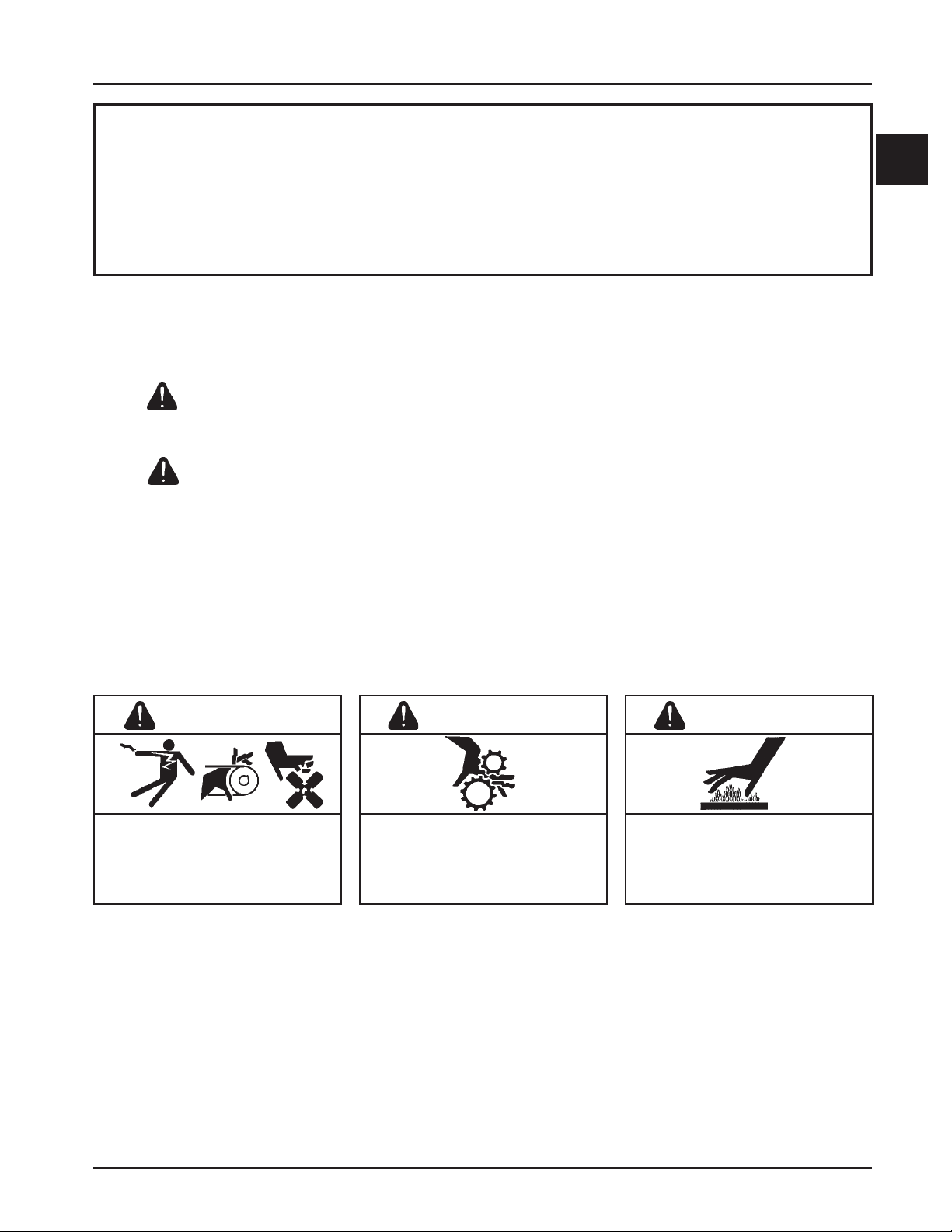
WARNING
Accidental Starts can cause severe
injury or death.
Disconnect and ground spark plug
lead before servicing.
Accidental St arts!
Disabling engine. Accidental
starting can cause severe injury or
death. Before working on the engine or
equipment, disable the engine as
follows: 1) Disconnect the spark plug
lead(s). 2) Disconnect negative (-)
battery cable from battery.
Rotating Parts can cause severe
injury.
Stay away while engine is in
operation.
Rotating Part s!
Keep hands, feet, hair, and clothing
away from all moving parts to prevent
injury. Never operate the engine with
covers, shrouds, or guards removed.
WARNING
WARNING
Hot Parts can cause severe burns.
Do not touch engine while operating
or just after stopping.
Hot Parts!
Engine components can get extremely
hot from operation. To prevent severe
burns, do not touch these areas while
the engine is running - or immediately
after it is turned off. Never operate the
engine with heat shields or guards
removed.
1.1
Page 4
Section 1
Safety and General Information
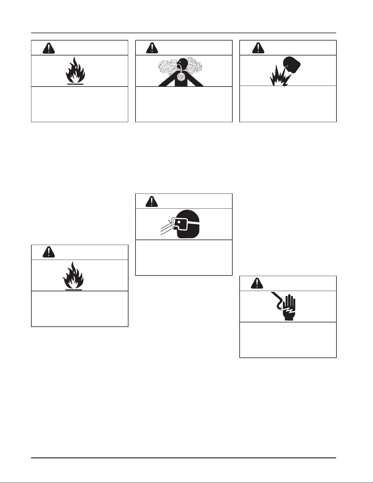
WARNING
Explosive Fuel can cause fires and
severe burns.
Do not fill the fuel tank while the
engine is hot or running.
Explosive Fuel!
Gasoline is extremely flammable and
its vapors can explode if ignited. Store
gasoline only in approved containers,
in well ventilated, unoccupied
buildings, away from sparks or flames.
Do not fill the fuel tank while the
engine is hot or running, since spilled
fuel could ignite if it comes in contact
with hot parts or sparks from ignition.
Do not start the engine near spilled
fuel. Never use gasoline as a cleaning
agent.
WARNING
WARNING WARNING
Carbon Monoxide can cause severe
nausea, fainting or death.
Avoid inhaling exhaust fumes, and
never run the engine in a closed
building or confined area.
Lethal Exhaust Gases!
Engine exhaust gases contain
poisonous carbon monoxide. Carbon
monoxide is odorless, colorless, and can
cause death if inhaled. Avoid inhaling
exhaust fumes, and never run the
engine in a closed building or confined
area.
WARNING
Uncoiling Spring can cause severe
injury.
Wear safety goggles or face
protection when servicing
retractable starter.
Explosive Gas can cause fires and
severe acid burns.
Charge battery only in a well
ventilated area. Keep sources of
ignition away.
Explosive Gas!
Batteries produce explosive hydrogen
gas while being charged. To prevent a
fire or explosion, charge batteries only
in well ventilated areas. Keep sparks,
open flames, and other sources of
ignition away from the battery at all
times. Keep batteries out of the reach of
children. Remove all jewelry when
servicing batteries.
Before disconnecting the negative
(-) ground cable, make sure all switches
are OFF. If ON, a spark will occur at
the ground cable terminal which could
cause an explosion if hydrogen gas or
gasoline vapors are present.
Cleaning Solvents can cause severe
injury or death.
Use only in well ventilated areas
away from ignition sources.
Flammable Solvents!
Carburetor cleaners and solvents are
extremely flammable. Keep sparks,
flames, and other sources of ignition
away from the area. Follow the cleaner
manufacturer’s warnings and
instructions on its proper and safe use.
Never use gasoline as a cleaning agent.
Spring Under T ension!
Retractable starters contain a powerful,
recoil spring that is under tension.
Always wear safety goggles when
servicing retractable starters and
carefully follow instructions in the
Retractable Starter Section 7 for relieving
spring tension.
CAUTION
Electrical Shock can cause injury.
Do not touch wires while engine is
running.
Electrical Shock!
Never touch electrical wires or
components while the engine is
running. They can be sources of
electrical shock.
1.2
Page 5
Engine Identification Numbers
When ordering parts, or in any communication
involving an engine, always give the Model,
Specification, and Serial Numbers, including letter
suffixes if any.
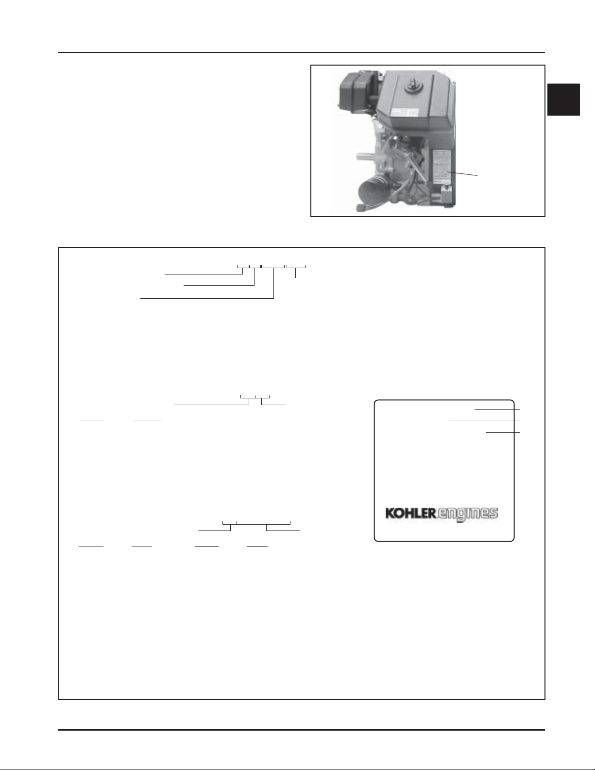
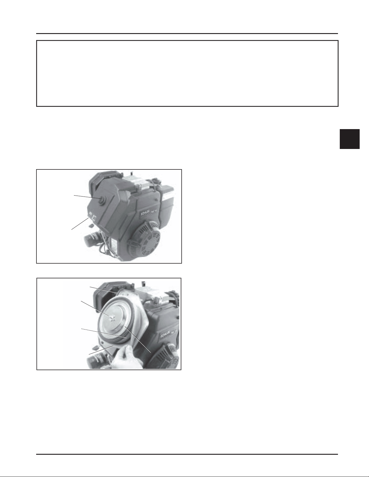
The engine identification numbers appear on a decal,
or decals, affixed to the engine shrouding. See Figure
1-1. An explanation of these numbers is shown in
Figure 1-2.
Section 1
Safety and General Information
1
Identification
Decal
Figure 1-1. Engine Identification Decal Location.
A. Model No.
Command Engine
Horizontal Crankshaft
Horsepower
11 = 11 HP
12.5 = 12.5 HP
13 = 13 HP
14 = 14 HP
15 = 15 HP
16 = 16 HP
B. Spec. No.
Engine Model Code
Code Model
16 CH11
19 CH12.5
22 CH13
18 CH14
44 CH15
45 CH16
C. Serial No.
Year Manufactured Code
Code Year
20 1990
21 1991
22 1992
23 1993
24 1994
25 1995
26 1996
27 1997
28 1998
C H 12.5 ST
1903
2005810334
Code Year
29 1999
30 2000
31 2001
32 2002
33 2003
34 2004
35 2005
36 2006
37 2007
Version Code
S = Electric Start
T = Retractable S t art
ST = Electric/Retractable S tart
GT = Generator Application/Retractable Start
GS = Generator Application/Electric Start
PT = Pump/Retractable S t art
RT = Gear Reduction/Retractable Start
Variation of
Basic Engine
Factory Code
MODEL NO.
SPEC. NO.
SERIAL NO.
REFER TO OWNER'S MANUAL FOR
SAFETY, MAINTENANCE SPECS
AND ADJUSTMENTS. FOR SALES
AND SERVICE IN US/CANADA
CALL: 1-800-544-2444.
www.kohlerengines.com
KOHLER CO. KOHLER, WI USA
CH12.5ST
1903
2005810334
A
B
C
Figure 1-2. Explanation of Engine Identification Numbers.
1.3
Page 6
Section 1
Safety and General Information
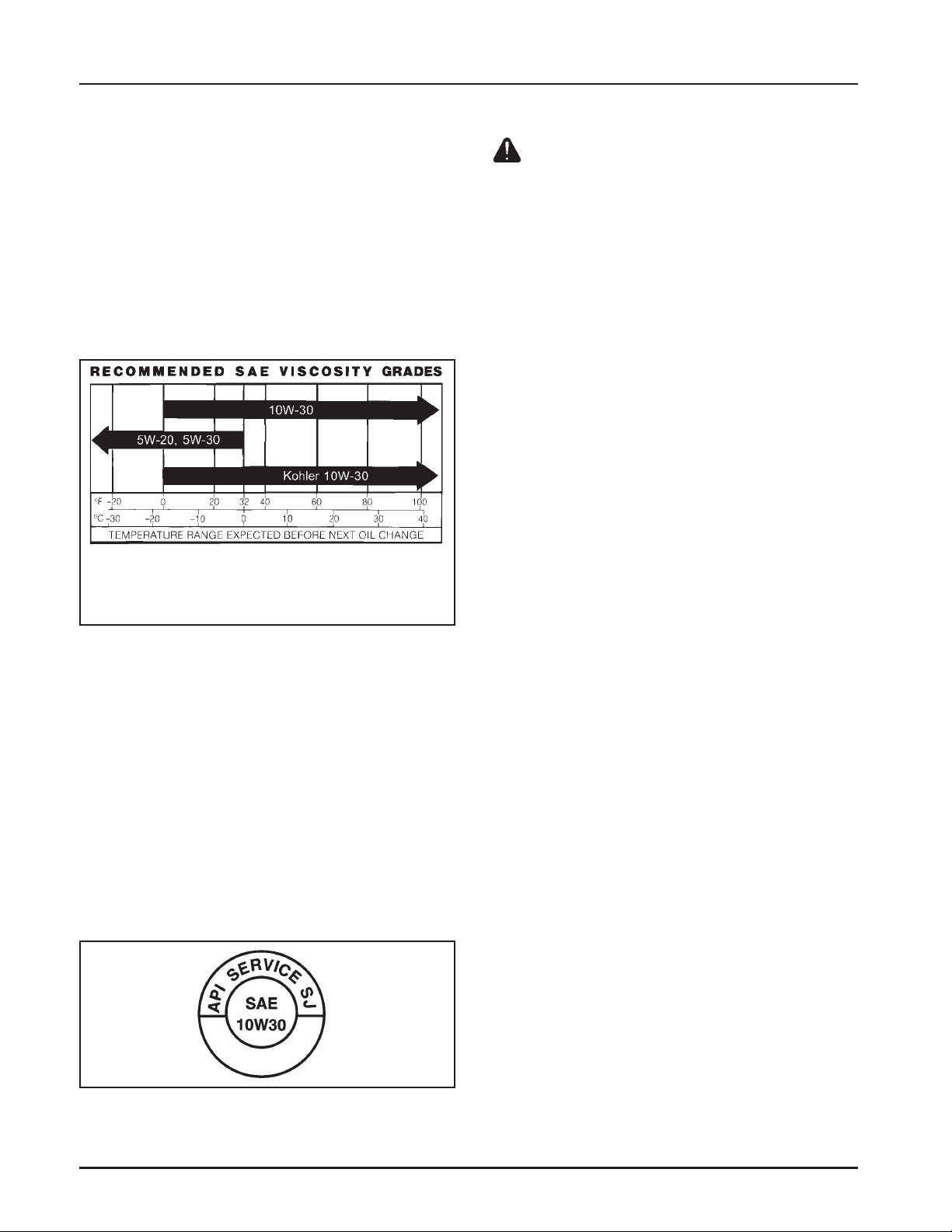
Oil Recommendations
Using the proper type and weight of oil in the
crankcase is extremely important. So is checking oil
daily and changing oil regularly. Failure to use the
correct oil, or using dirty oil, causes premature engine
wear and failure.
Oil Type
Use high-quality detergent oil of API (American
Petroleum Institute) service class SG, SH, SJ, or
higher. Select the viscosity based on the air
temperature at the time of operation as shown in the
following table.
**
*Use of synthetic oil having 5W-20 or 5W-30 rating is
acceptable, up to 4°C (40°F).
**Synthetic oils will provide better starting in
extreme cold below 23°C (-10°F).
NOTE: Using other than service class SG, SH, SJ, or
higher oil or extending oil change intervals
longer than recommended can cause engine
damage.
*
Fuel Recommendations
WARNING: Explosive Fuel!
Gasoline is extremely flammable and its vapors can explode if
ignited. Store gasoline only in approved containers, in well
ventilated, unoccupied buildings, away from sparks or flames.
Do not fill the fuel tank while the engine is hot or running,
since spilled fuel could ignite if it comes in contact with hot
parts or sparks from ignition. Do not start the engine near
spilled fuel. Never use gasoline as a cleaning agent.
General Recommendations
Purchase gasoline in small quantities and store in
clean, approved containers. A container with a
capacity of 2 gallons or less with a pouring spout is
recommended. Such a container is easier to handle
and helps eliminate spilling during refueling.
Do not use gasoline left over from the previous season,
to minimize gum deposits in your fuel system and to
ensure easy starting.
Do not add oil to the gasoline.
Do not overfill the fuel tank. Leave room for the fuel to
expand.
Fuel Type
For best results, use only clean, fresh, unleaded
gasoline with a pump sticker octane rating of 87 or
higher. In countries using the Research method, it
should be 90 octane minimum.
NOTE: Synthetic oils meeting the listed
classifications may be used with oil changes
performed at the recommended intervals.
However to allow piston rings to properly
seat, a new or rebuilt engine should be
operated for at least 50 hours using standard
petroleum based oil before switching to
synthetic oil.
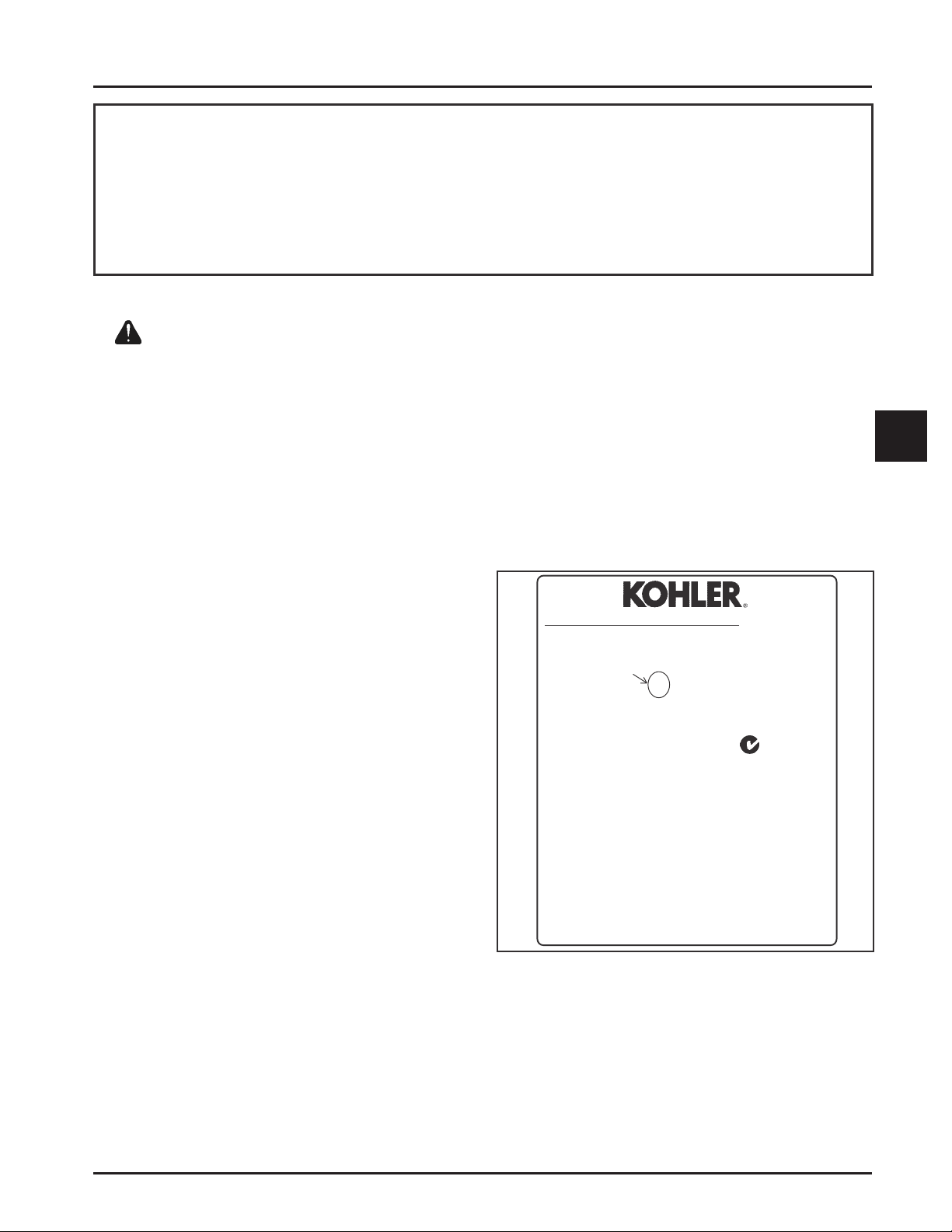
A logo or symbol on oil containers identifies the API
service class and SAE viscosity grade. See Figure 1-3.
Figure 1-3. Oil Container Logo.
Refer to Section 6 Lubrication System for detailed oil
check, oil change, and oil filter procedures.
Unleaded gasoline is recommended, as it leaves less
combustion chamber deposits. Leaded gasoline may
be used in areas where unleaded is not available and
exhaust emissions are not regulated. Be aware
however, that the cylinder head will require more
frequent service.
Gasoline/Alcohol blends
Gasohol (up to 10% ethyl alcohol, 90% unleaded
gasoline by volume) is approved as a fuel for Kohler
engines. Other gasoline/alcohol blends are not
approved.
Gasoline/Ether blends
Methyl Tertiary Butyl Ether (MTBE) and unleaded
gasoline blends (up to maximum of 15% MTBE by
volume) are approved as a fuel for Kohler engines.
Other gasoline/ether blends are not approved.
1.4
Page 7

Periodic Maintenance
Section 1
Safety and General Information
WARNING: Accident al St arts!
Disabling engine. Accidental starting can cause severe injury or death. Before working on the engine or equipment,
disable the engine as follows: 1) Disconnect the spark plug lead(s). 2) Disconnect negative (-) battery cable from battery.
Maintenance Schedule
The following required maintenance procedures should be performed at the frequency stated in the table and
should also be included as part of any seasonal tune-up.
Frequency
• Fill fuel tank.
Daily or Before
Starting Engine
Every 25 Hours
Every 50 Hours
Every
100 Hours
Every
200 Hours
Annually or Every
500 Hours
1
Perform these maintenance procedures more frequently under extremely dusty, dirty conditions.
2
Only required for Denso starters. Not necessary on Delco starters. Have a Kohler Engine Service Dealer perform this service.
• Check oil level.
• Check air cleaner for dirty1, loose, or damaged parts.
• Check air intake and cooling areas, clean as necessary1.
• Service precleaner element1.
• Check oil level in gear reduction unit.
• Replace air cleaner element1.
• Change oil1.
• Remove cooling shrouds and clean cooling areas1.
• Change oil filter.
• Check spark plug condition and gap.
• Replace fuel filter.
• Have bendix starter drive serviced2.
• Have solenoid shift starter disassembled and cleaned2.
Maintenance Required
Refer to:
Section 5
Section 6
Section 4
Section 4
Section 4
Section 6
Section 4
Section 6
Section 4
Section 6
Section 8
Section 5
Section 8
Section 8
1
Storage
If the engine will be out of service for two months or
more, use the following storage procedure:
1. Clean the exterior surfaces of the engine.
2. Change the oil and oil filter while the engine is
still warm from operation. See Change Oil and
Oil Filter in Section 6.
3. The fuel system must be completely emptied, or
the gasoline must be treated with a stabilizer to
prevent deterioration. If you choose to use a
stabilizer, follow the manufacturers
recommendations, and add the correct amount
for the capacity of the fuel system. Fill the fuel
tank with clean, fresh gasoline. Run the engine
for 2-3 minutes to get stabilized fuel into the
carburetor.
To empty the system, run the engine until the
tank and system are empty.
4. Remove the spark plug. Add one tablespoon of
engine oil into the spark plug hole. Install the
plug, but do not connect the plug lead. Crank the
engine two or three revolutions.
5. Remove the spark plug. Cover the spark plug
hole with your thumb, and turn the engine over
until the piston is at the top of its stroke.
(Pressure against thumb is greatest.) Reinstall
the plug, but do not connect the plug lead.
6. Store the engine in a clean, dry place.
1.5
Page 8
Section 1
Safety and General Information
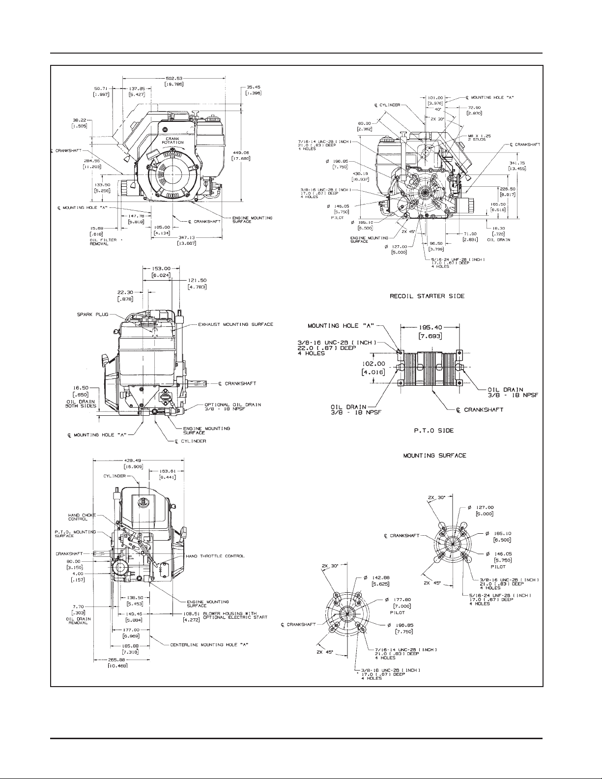
Dimensions in millimeters.
Inch equivalents shown in ( ).
Figure 1-4. T ypical Engine Dimensions.
1.6
Page 9

Section 1
Safety and General Information
General Specifications
Power (@ 3600 RPM, exceeds SAE J1940 HP standards)
CH11 .......................................................................................................... 8.20 kW (11 HP)
CH12.5 ....................................................................................................... 9.33 kW (12.5 HP)
CH13 .......................................................................................................... 9.75 kW (13 HP)
CH14 .......................................................................................................... 10.50 kW (14 HP)
CH15 .......................................................................................................... 11.20 kW (15 HP)
CH16 .......................................................................................................... 11.90 kW (16 HP)
Peak Torque (@ RPM indicated)
CH11 (@ 2400 RPM) ................................................................................. 26.7 N·m (19.7 ft. lb)
CH12.5 (@ 2500 RPM) .............................................................................. 27.8 N·m (20.5 ft. lb)
CH13 (@ 2400 RPM) ................................................................................. 28.8 N·m (21.2 ft. lb)
CH14 (@ 2500 RPM) ................................................................................. 27.8 N·m (21.3 ft. lb)
CH15 (@ 2400 RPM) ................................................................................. 34.3 N·m (25.3 ft. lb)
CH16 (@ 2400 RPM) ................................................................................. 33.9 N·m (25.0 ft. lb)
Bore
CH11, CH12.5, CH13, CH14 .................................................................... 87 mm (3.43 in.)
CH15, CH16 .............................................................................................. 90 mm (3.54 in.)
Stroke ................................................................................................................ 67 mm (2.64 in.)
Displacement
CH11, CH12.5, CH13, CH14 .................................................................... 398 cc (24.3 cu. in.³)
CH15, CH16 .............................................................................................. 426 cc (26.0 cu. in.³)
1
1
Compression Ratio ......................................................................................... 8.5:1
Weight .............................................................................................................. 40 kg (88.3 lb.)
Max. Oil Capacity (w/filter) .......................................................................... 1.9 L (2.0 qt.)
Lubrication ...................................................................................................... full pressure w/full flow filter
Air Cleaner
Base Nut Torque .............................................................................................. 9.9 N·m (88 in. lb.)
Angle of Operation - Maximum (at full oil level)
Intermittent - All Directions ......................................................................... 35°
Continuous - All Directions .......................................................................... 25°
Balance Shaft
End Play (Free) ................................................................................................ 0.0575/0.3625 mm (0.0023/0.0137 in.)
Running Clearance ......................................................................................... 0.025/0.1520 mm (0.0009/0.0059 in.)
Bore I.D.
New ........................................................................................................... 20.000/20.025 mm (0.7874/0.7884 in.)
Max. Wear Limit ...................................................................................... 20.038 mm (0.7889 in.)
Balance Shaft Bearing Surface O.D.
New ........................................................................................................... 19.962/19.975 mm (0.7859/0.7864 in.)
Max. Wear Limit ...................................................................................... 19.959 mm (0.7858 in.)
1
Values are in Metric units. Values in parentheses are English equivalents. Lubricate threads with engine oil prior to
assembly.
1.7
Page 10

Section 1
Safety and General Information
Camshaft
End Play (Free) ................................................................................................ 0.0875/0.3925 mm (0.0034/0.0154 in.)
End Play (with Shims) ................................................................................... 0.0762/0.1270 mm (0.0030/0.0050 in.)
Running Clearance ......................................................................................... 0.025/0.1050 mm (0.00098/0.0041 in.)
Bore I.D.
New ........................................................................................................... 20.000/20.025 mm (0.7874/0.7884 in.)
Max. Wear Limit ...................................................................................... 20.038 mm (0.7889 in.)
Camshaft Bearing Surface O.D.
New ........................................................................................................... 19.962/19.975 mm (0.7859/0.7864 in.)
Max. Wear Limit ...................................................................................... 19.959 mm (0.7858 in.)
Carburetor
Fuel Bowl Nut Torque .................................................................................... 5.1-6.2 N·m (45-55 in. lb.)
Charging
Stator Mounting Screw Torque .................................................................... 6.2 N·m (55 in. lb.)
Closure Plate
Oil Filter Tightening....................................................................................... 3/4-1 turn after gasket contacts.
Oil Filter Adapter Fastener Torque .............................................................. 11.3 N·m (100 in. lb.)
Oil Filter Drain Plug (1/8" NPT) Torque....................................................... 7.3-9.0 N·m (65-80 in. lb.)
Closure Plate Fastener Torque ...................................................................... 24.4 N·m (216 in. lb.)
Oil Sentry Pressure Switch Torque .............................................................. 6.8 N·m (60 in. lb.)
Oil Pump Cover Fastener Torque² ............................................................... 4.0,6.2 N·m (35,55 in. lb.)
Connecting Rod
Cap Fastener Torque
6 mm straight shank bolt....................................................................... 11.3 N·m (100 in. lb.)
8 mm straight shank bolt....................................................................... 22.6 N·m (200 in. lb.)
8 mm step-down type bolt .................................................................... 14.7 N·m (130 in. lb.)
Connecting Rod-to-Crankpin Running Clearance at 21°C (70°F)
New ........................................................................................................... 0.030/0.055 mm (0.0012/0.0022 in.)
Max. Wear Limit ...................................................................................... 0.07 mm (0.0025 in.)
Connecting Rod-to-Crankpin Side Clearance ............................................ 0.18/0.41 mm (0.007/0.016 in.)
Connecting Rod-to-Piston Pin Running Clearance 21°C (70°F) ............... 0.015/0.028 mm (0.0006/0.0011 in.)
Piston Pin End I.D.
New ........................................................................................................... 19.015/19.023 mm (0.7486/0.7489 in.)
Max. Wear Limit ...................................................................................... 19.036 mm (0.7495 in.)
Crankcase
Governor Cross Shaft Bore I.D.
New ........................................................................................................... 6.025/6.050 mm (0.2372/0.2382 in.)
Max. Wear Limit ...................................................................................... 6.063 mm (0.2387 in.)
2
For self-tapping (thread-forming) fasteners, the higher torque value is for installation into a new cored (non-threaded) hole.
The lower torque value is for installation into a used or threaded hole.
1.8
Page 11

Section 1
Safety and General Information
Crankshaft
End Play (Free) ................................................................................................ 0.0575/0.4925 mm (0.0022/0.0193 in.)
End Play (Thrust Bearing with Shims) ....................................................... 0.0500/0.5300 mm (0.0019/0.0208 in.)
Crankshaft Bearing I.D. (In Crankcase)
Sleeve Bearing (Installed) - New ........................................................... 44.965/45.003 mm (1.7703/1.7718 in.)
Sleeve Bearing - Max. Wear Limit ......................................................... 45.016 mm (1.7723 in.)
Parent Material (No Sleeve Bearing) - New ........................................ 44.965/44.990 mm (1.7703/1.7713 in.)
Parent Material (No Sleeve Bearing) - Max. Wear Limit ................... 45.003 mm (1.7718 in.)
Crankshaft to Bearing Running Clearance - New
Sleeve Bearing .......................................................................................... 0.030/0.090 mm (0.0011/0.0035 in.)
Parent Material (No Sleeve Bearing) .................................................... 0.030/0.077 mm (0.0011/0.0030 in.)
Crankshaft Bearing I.D. (In Closure Plate)
Sleeve Bearing (Installed) - New ........................................................... 41.960/42.035 mm (1.6519/1.6549 in.)
Sleeve Bearing - Max. Wear Limit ......................................................... 42.048 mm (1.6554 in.)
Parent Material (No Sleeve Bearing) - New ........................................ 41.965/42.003 mm (1.6521/1.6536 in.)
Parent Material (No Sleeve Bearing) - Max. Wear Limit ................... 42.015 mm (1.6541 in.)
Crankshaft Bore (In Closure Plate) to Crankshaft Running Clearance - New
Sleeve Bearing .......................................................................................... 0.025/0.1200 mm (0.00098/0.00472 in.)
Parent Material (No Sleeve Bearing) .................................................... 0.030/0.0880 mm (0.0011/0.0034 in.)
1
Flywheel End Main Bearing Journal
O.D. - New ................................................................................................ 44.913/44.935 mm (1.7682/1.7691 in.)
O.D. - Max. Wear Limit ........................................................................... 44.84 mm (1.765 in.)
Max. Taper ................................................................................................ 0.022 mm (0.0009 in.)
Max. Out-of-Round ................................................................................. 0.025 mm (0.0010 in.)
Closure Plate End Main Bearing Journal
O.D. - New ................................................................................................ 41.915/41.935 mm (1.6502/1.6510 in.)
O.D. - Max. Wear Limit ........................................................................... 41.86 mm (1.648 in.)
Max. Taper ................................................................................................ 0.020 mm (0.0008 in.)
Max. Out-of-Round ................................................................................. 0.025 mm (0.0010 in.)
Connecting Rod Journal
O.D. - New ................................................................................................ 38.958/38.970 mm (1.5338/1.5343 in.)
O.D. - Max. Wear Limit ........................................................................... 38.94 mm (1.5328 in.)
Max. Taper ................................................................................................ 0.012 mm (0.0005 in.)
Max. Out-of-Round ................................................................................. 0.025 mm (0.0010 in.)
Crankshaft T.I.R.
PTO End, Crank in Engine ...................................................................... 0.304 mm (0.012 in.)
Entire Crank, in V-Blocks ....................................................................... 0.10 mm (0.0039 in.)
Cylinder Bore
Cylinder Bore I.D.
New
CH11-14 .................................................................................................. 87.000/87.025 mm (3.4252/3.4262 in.)
CH15, CH16 ............................................................................................ 90.000/90.025 mm (3.5433/3.5442 in.)
Max. Wear Limit
CH11-14 .................................................................................................. 87.063 mm (3.4277 in.)
CH15, CH16 ............................................................................................ 90.063 mm (3.5457 in.)
1.9
Page 12

Section 1
Safety and General Information
Cylinder Bore I.D. cont'd.
Max. Out-of-Round
CH11-14 .................................................................................................. 0.12 mm (0.0047 in.)
CH15, CH16 ............................................................................................ 0.12 mm (0.0047 in.)
Max. Taper
CH11-14 .................................................................................................. 0.05 mm (0.0020 in.)
CH15, CH16 ............................................................................................ 0.05 mm (0.0020 in.)
Cylinder Head
Cylinder Head Fastener Torque (torque in 2 increments) ........................ 24,48.9 N·m (18,36 ft. lb.)
Max. Out-of-Flatness ...................................................................................... 0.076 mm (0.003 in.)
Rocker Pedestal Fastener Torque ................................................................. 9.9 N·m (88 in. lb.)
Electric Starter
Thru Bolt Torque
UTE/Johnson Electric, Eaton (Inertia Drive) ..................................... 4.5-5.7 N·m (40-50 in. lb.)
Nippondenso (Solenoid Shift) ............................................................ 4.5-7.5 N·m (40-84 in. lb.)
Delco-Remy (Solenoid Shift) ............................................................... 5.6-9.0 N·m (49-79 in. lb)
Drive Pinion Fastener Torque (some Inertia Drive Starters) .................... 15.3 N·m (135 in. lb.)
Brush Holder Mounting Screw Torque
Delco-Remy Starter ............................................................................. 2.5-3.3 N·m (22-29 in. lb.)
Solenoid (Starter)
Mounting Hardware Torque
Nippondenso Starter .......................................................................... 6.0-9.0 N·m (53-79 in. lb.)
Delco-Remy Starter ............................................................................. 4.0-6.0 N·m (35-53 in. lb.)
Nut, Positive (+) Brush Lead Torque
Nippondenso Starter .......................................................................... 8.0-12.0 N·m (71-106 in. lb)
Delco-Remy Starter ............................................................................. 6.0-9.0 N·m (53-79 in. lb.)
Fan/Flywheel
Fan Fastener Torque ....................................................................................... 9.9 N·m (88 in. lb.)
Flywheel Retaining Screw Torque ............................................................... 66.4 N·m (49 ft. lb.)
Fuel Pump
Fuel Pump/Cover Fastener Screw Torque .................................................. 9.0 N·m (80 in. lb.) into new holes
4.2-5.1 N·m (37-45 in. lb.) into used holes
Fuel Tank
Fuel Tank Fastener Torque ............................................................................. 7.3 N·m (65 in. lb.)
Governor
Governor Cross Shaft to Crankcase Running Clearance
Governor Cross Shaft O.D.
Governor Gear Shaft-to-Governor Gear Running Clearance
Governor Gear Shaft O.D.
1.10
...........................................................................................................
New
Max. Wear Limit
...........................................................................................................
New
Max. Wear Limit
......................................................................................
......................................................................................
.........................
.................
0.025/0.075 mm (0.0010/0.0030 in.)
5.975/6.000 mm (0.2352/0.2362 in.)
5.962 mm (0.2347 in.)
0.015/0.140 mm (0.0006/0.0055 in.)
5.990/6.000 mm (0.2358/0.2362 in.)
5.977 mm (0.2353 in.)
Page 13

Safety and General Information
Ignition
Spark Plug Type (Champion® or equivalent) ............................................. RC12YC or Platinum 3071
Section 1
Spark Plug Gap
CH11-15 .................................................................................................... 1.02 mm (0.040 in.)
CH16 .......................................................................................................... 0.76 mm (0.030 in.)
Spark Plug Torque .......................................................................................... 38.0-43.4 N·m (28-32 ft. lb.)
Ignition Module Air Gap ............................................................................... 0.203/0.305 mm (0.008/0.012 in.)
Ignition Module Fastener Torque ................................................................. 4.0 N·m (35 in. lb.) into new holes
6.2 N·m (55 in. lb.) into used holes
Muffler
Muffler Retaining Nuts .................................................................................. 24.4 N·m (216 in. lb.)
Piston, Piston Rings, and Piston Pin
Piston-to-Piston Pin (selective fit) ............................................................... 0.006/0.017 mm (0.0002/0.0007 in.)
Piston Pin Bore I.D.
New ........................................................................................................... 19.006/19.012 mm (0.7483/0.7485 in.)
Max. Wear Limit ...................................................................................... 19.025 mm (0.7490 in.)
Piston Pin O.D.
New ........................................................................................................... 18.995/19.000 mm (0.7478/0.7480 in.)
Max. Wear Limit ...................................................................................... 18.994 mm (0.74779 in.)
Top Compression Ring-to-Groove Side Clearance
CH11-14 .................................................................................................... 0.040/0.105 mm (0.0016/0.0041 in.)
CH15, CH16 .............................................................................................. 0.060/0.105 mm (0.0023/0.0041 in.)
1
Middle Compression Ring-to-Groove Side Clearance
CH11-14 .................................................................................................... 0.040/0.072 mm (0.0016/0.0028 in.)
CH15, CH16 .............................................................................................. 0.040/0.085 mm (0.0015/0.0002 in.)
Oil Control Ring-to-Groove Side Clearance
CH11-14 .................................................................................................... 0.551/0.675 mm (0.0217/0.0266 in.)
CH15, CH16 .............................................................................................. 0.176/0.026 (0.0069/0.0010 in.)
Top and Center Compression Ring End Gap
New Bore
CH11-14 ................................................................................................ 0.3/0.5 mm (0.012/0.020 in.)
CH15, CH16 .......................................................................................... 0.27/0.51 mm (0.010/0.020 in.)
Used Bore (Max.) ...................................................................................... 0.77 mm (0.030 in.)
Piston Thrust Face O.D.
New
CH11-14
CH15, CH164......................................................................................... 89.951/89.969 mm (3.5413/3.5420 in.)
Max. Wear Limit
CH11-14 ................................................................................................ 86.814 mm (3.4179 in.)
CH15, CH16 .......................................................................................... 89.824 mm (3.5363 in.)
3
Measure 6 mm (0.236 in.) above the bottom of the piston skirt at right angles to the piston pin.
4
Measure 8 mm (0.314 in.) above the bottom of the piston skirt at right angles to the piston pin.
3
............................................................................................... 86.941/86.959 mm (3.4229/3.4236 in.)
1.11
Page 14

Section 1
Safety and General Information
Piston Thrust Face-to-Cylinder Bore Running Clearance - New
CH11-14 .................................................................................................... 0.041/0.044 mm (0.0016/0.0017 in.)
CH15, CH16 .............................................................................................. 0.031/0.043 mm (0.0012/0.0016 in.)
Retractable Starter
Center Screw Torque ...................................................................................... 7.4-8.5 N·m (65-75 in. lb.)
Throttle/Choke Controls
Governor Control Lever Fastener Torque .................................................. 9.9 N·m (88 in. lb.)
Speed Control Bracket Assembly Fastener Torque² .................................. 7.3-10.7 N·m (65-95 in. lb.)
Valve Cover/Rocker Arms
Valve Cover Fastener Torque² ...................................................................... 7.3-10.7 N·m (65-95 in. lb.)
Rocker Arm I.D.
New ........................................................................................................... 15.837/16.127 mm (0.63/0.64 in.)
Max. Wear Limit ...................................................................................... 16.13 mm (0.640 in.)
Rocker Shaft O.D.
New ........................................................................................................... 15.90/15.85 mm (0.63 in.)
Max. Wear Limit ...................................................................................... 15.727 mm (0.619 in.)
Valves and Valve Lifters
Hydraulic Valve Lifter to Crankcase Running Clearance ........................ 0.0124/0.0501 mm (0.0005/0.0020 in.)
Intake Valve Stem-to-Valve Guide Running Clearance ........................... 0.038/0.076 mm (0.0015/0.0030 in.)
Exhaust Valve Stem-to-Valve Guide Running Clearance ........................ 0.050/0.088 mm (0.0020/0.0035 in.)
Intake Valve Guide I.D.
New ........................................................................................................... 7.038/7.058 mm (0.2771/0.2779 in.)
Max. Wear Limit ...................................................................................... 7.134 mm (0.2809 in.)
Exhaust Valve Guide I.D.
New ........................................................................................................... 7.038/7.058 mm (0.2771/0.2779 in.)
Max. Wear Limit ...................................................................................... 7.159 mm (0.2819 in.)
Valve Guide Reamer Size
STD ............................................................................................................. 7.048 mm (0.2775 in.)
0.25 mm O.S. ............................................................................................. 7.298 mm (0.2873 in.)
Intake Valve Minimum Lift ........................................................................... 8.96 mm (0.353 in.)
Exhaust Valve Minimum Lift ....................................................................... 9.14 mm (0.360 in.)
Nominal Valve Seat Angle ............................................................................ 45°
2
For self-tapping (thread-forming) fasteners, the higher torque value is for installation into a new cored (non-threaded) hole.
The lower torque value is for installation into a used or threaded hole.
1.12
Page 15
General Torque Values
Section 1
Safety and General Information
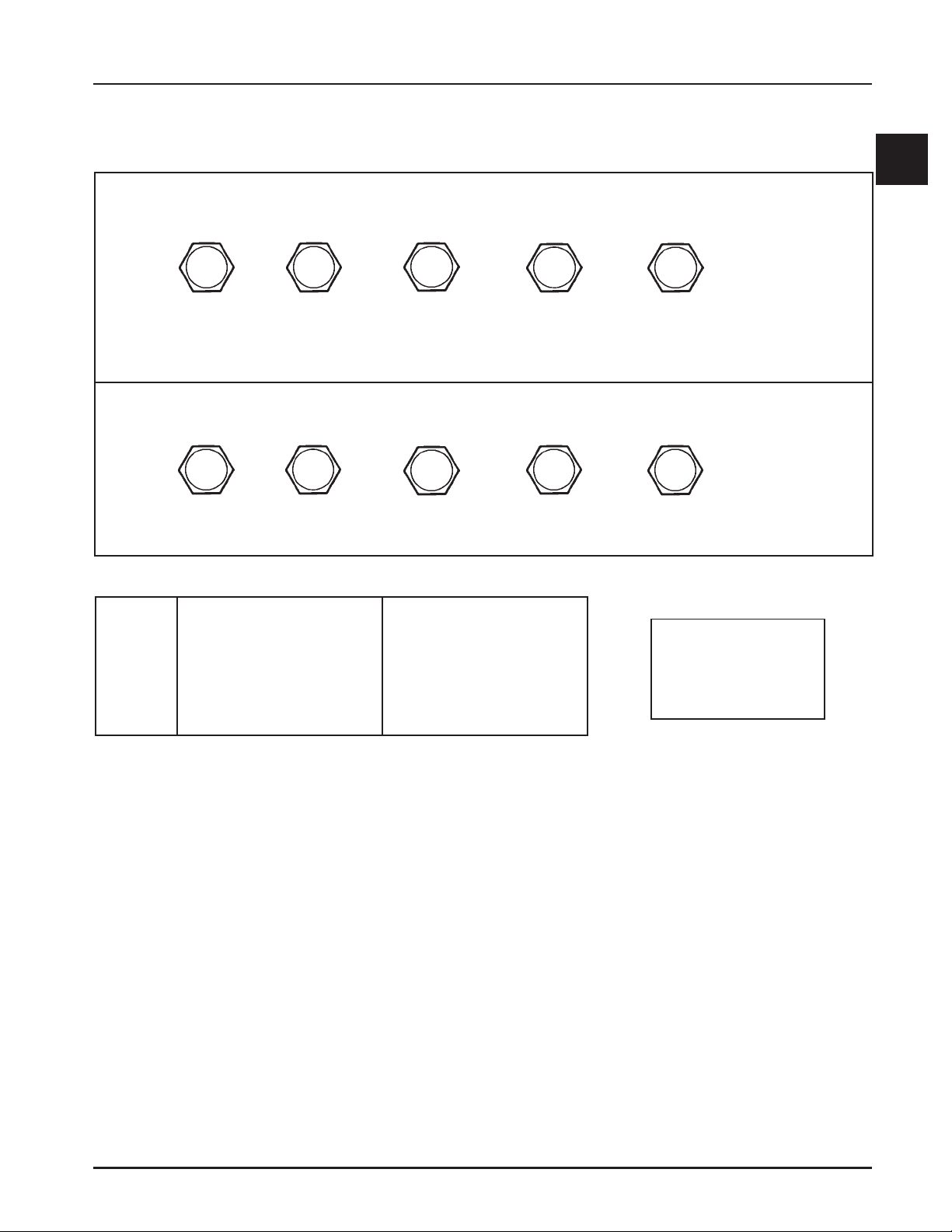
Metric Fastener T orque Recommendations for St andard Applications
Tightening Torque: N·m (in. lb.) + or - 10%
Property Class
Noncritical
4.8
Size
M4 1.2 (11) 1.7 (15) 2.9 (26) 4.1 (36) 5.0 (44) 2.0 (18)
M5 2.5 (22) 3.2 (28) 5.8 (51) 8.1 (72) 9.7 (86) 4.0 (35)
M6 4.3 (38) 5.7 (50) 9.9 (88) 14.0 (124) 16.5 (146) 6.8 (60)
M8 10.5 (93) 13.6 (120) 24.4 (216) 33.9 (300) 40.7 (360) 17.0 (150)
5.8 8.8 10.9 12.9
Fasteners
Into Aluminum
Tightening Torque: N·m (ft. lb.) + or - 10%
Property Class
4.8
M10 21.7 (16) 27.1 (20) 47.5 (35) 66.4 (49) 81.4 (60) 33.9 (25)
M12 36.6 (27) 47.5 (35) 82.7 (61) 116.6 (86) 139.7 (103) 61.0 (45)
M14 58.3 (43) 76.4 (55) 131.5 (97) 184.4 (136) 219.7 (162) 94.9 (70)
5.8 8.8 10.9 12.9
Oil Drain Plugs Tightening Torque: N·m (English Equiv.)
Size
1/8" NPT
1/4"
3/8"
1/2"
3/4"
X-708-1
Into Cast Iron
–
17.0 (150 in. lb.)
20.3 (180 in. lb.)
27.1 (20 ft. lb.)
33.9 (25 ft. lb.)
27.1/33.9 (20/25 ft. lb.)
Into Aluminum
4.5 (40 in. lb.)
11.3 (100 in. lb.)
13.6 (120 in. lb.)
17.6 (13 ft. lb.)
21.7 (16 ft. lb.)
27.1/33.9 (20/25 ft. lb.)
Conversions
N·m = in. lb. x 0.113
N·m = ft. lb. x 1.356
in. lb. = N·m x 8.85
ft. lb. = N·m x 0.737
Noncritical
Fasteners
Into Aluminum
Torque
1
1.13
Page 16

Section 2
Tools & Aids
Section 2
Tools & Aids
Certain quality tools are designed to help you perform specific disassembly, repair, and reassembly procedures.
By using tools designed for the job, you can properly service engines easier, faster, and safer! In addition, you’ll
increase your service capabilities and customer satisfaction by decreasing engine downtime.
Here is the list of tools and their source.
Separate Tool Suppliers:
Kohler Tools
Contact your source
of supply.
SE Tools
415 Howard St.
Lapeer, MI 48446
Phone 810-664-2981
Toll Free 800-664-2981
Fax 810-664-8181
Design Technology Inc.
768 Burr Oak Drive
Westmont, IL 60559
Phone 630-920-1300
2
IFEtiKecivreS
slooT
noitpircseD .oNtraP/ecruoS
)seireSM&K(looTgnimiTraeGecnalaB
.enignegnilbmessanehwnoitisopdemitnisraegecnalabdlohoT
etalPyalpdnEtfahsmaC
.yalpdnetfahsmacgnikcehcroF
retseTnwodkaeLrednilyC
.nrowerasevlavro,sgnir,notsip,rednilycfidnanoitneternoitsubmocgnikcehcroF
erawtfoScitsongaiD)IFE(noitcejnIleuFcinortcelE
.CPpotkseDropotpaLhtiwesU
.enigneIFEnapugnittesdnagnitoohselbuortroF
elbaliavAstnenopmoClaudividnI
retseTerusserP
thgiLdioN
retpadA°09
sreilPpmalCrekiteO
eriWdeR,gulPedoC
eriWeulB,gulPedoC
S-6055452relhoK
)753-YylremroF(
50428-RLKslooTES
S-5016752relhoK
S-3216752relhoK
S-1016742relhoK
.cnIygolonhceTngiseD
910-ITD
120-ITD
320-ITD
520-ITD
720-ITD
920-ITD
)seireSSC(looTgnidloHleehwylF 70428-RLKslooTES
relluPleehwylF
.enignemorfleehwylfevomeroT
hcnerWpartSleehwylF
.lavomergnirudleehwylfdlohoT
80428-RLKslooTES
90428-RLKslooTES
2.1
Page 17

Section 2
Tools & Aids
).tnoc(slooT
noitpircseD .oNtraP/ecruoS
looTretfiLevlaVciluardyH
.sretfilciluardyhllatsnidnaevomeroT
retseTmetsySnoitingI
.DCtpecxe,smetsysllanotuptuognitsetroF
.metsysnoitingi)DC(egrahcsideviticapacnotuptuognitsetroF
)seireSM&K(hcnerWtesffO
.stungniniaterlerrabrednilycllatsnierdnaevomeroT
tiKtseTerusserPliO
.erusserplioyfirevdnatsetoT
)tnerructlov021(retseTrotalugeR-reifitceR
)tnerructlov042(retseTrotalugeR-reifitceR
.srotaluger-reifitcertsetotdesU
elbaliavAstnenopmoClaudividnI
ssenraHtseTrotalugeRORP-SC
edoiDhtiwssenraHtseTrotalugeRlaicepS
retseT)MAS(eludoMecnavdAkrapS
KRAPS-TRAMShtiwsenigneno)MASDdnaMASA(MASehttsetoT
.™
)tfihSdioneloS(looTgnidloHhsurBretratS
.gnicivresgnirudsehsurbdlohoT
S-8316752relhoK
S-1055452relhoK
S-2055442relhoK
01428-RLKslooTES
S-6016752relhoK
S-0216752relhoK
S-1416752relhoK
.cnIygolonhceTngiseD
130-ITD
330-ITD
S-0416752relhoK
61428-RLKslooTES
)evirDaitrenI(looTgniRgniniateRretratS
.)sretratsOCSAFgnidulcxe(sgnirgniniaterevirdllatsnierdnaevomeroT
)sretratSllA(tiKgnicivreSretratS
.sehsurbdnasgnirgniniaterevirdllatsnierdnaevomeroT
elbaliavAtnenopmoClaudividnI
)tfihSdioneloS(looTgnidloHhsurBretratS
)evitcudnIlatigiD(retemohcaT
.enignenafo)MPR(deepsgnitarepognikcehcroF
retseTerusserP/muucaV
.retemonamretawaotevitanretlA
)seireSM&K(remaeRediuGevlaV
.noitallatsniretfasediugevlavgnizisroF
)CHO,dnammoC,sigeA,egaruoC(tiKecivreSediuGevlaV
.sediugeulavnrowgnicivresroF
S-8116752relhoK
11428-RLKslooTES
61428-RLKslooTES
.cnIygolonhceTngiseD
011-ITD
S-2216752relhoK
31428-RLKslooTES
51428-RLKslooTES
2.2
Page 18

Section 2
Tools & Aids
sdiA
noitpircseD .oNtraP/ecruoS
tnacirbuLtfahsmaC )316ZZrapslaV( S-4175352relhoK
esaerGcirtceleiD )166GdraugavoN/EG( S-1175352relhoK
2
esaerGcirtceleiD )orP-leF( leS-irbuL
tnacirbuLevirDretratScirtcelE )evirDaitrenI( S-1075325relhoK
tnacirbuLevirDretratScirtcelE )tfihSdioneloS(S-2075325relhoK
®
etitcoL
.resnepsidlosoreazo4niydoByvaeH0095
tnalaeSenociliSVTR
S-7079552relhoK
.esurofdevorppaera,detsilesohtsahcus,stnalaesVTRtnatsiserlio,desab-emixoylnO
®
etitcoL
®
etitcoL
0195
®
etitcoL
®
etitcoL
®
etitcoL
895kcalBartlU
785eulBartlU
reppoCartlU
.scitsiretcarahcgnilaestsebrofdednemmocerera0195ro0095.soN
tnacirbuLevirDenilpS S-2175352relhoK
2.3
Page 19
Section 2
Tools & Aids
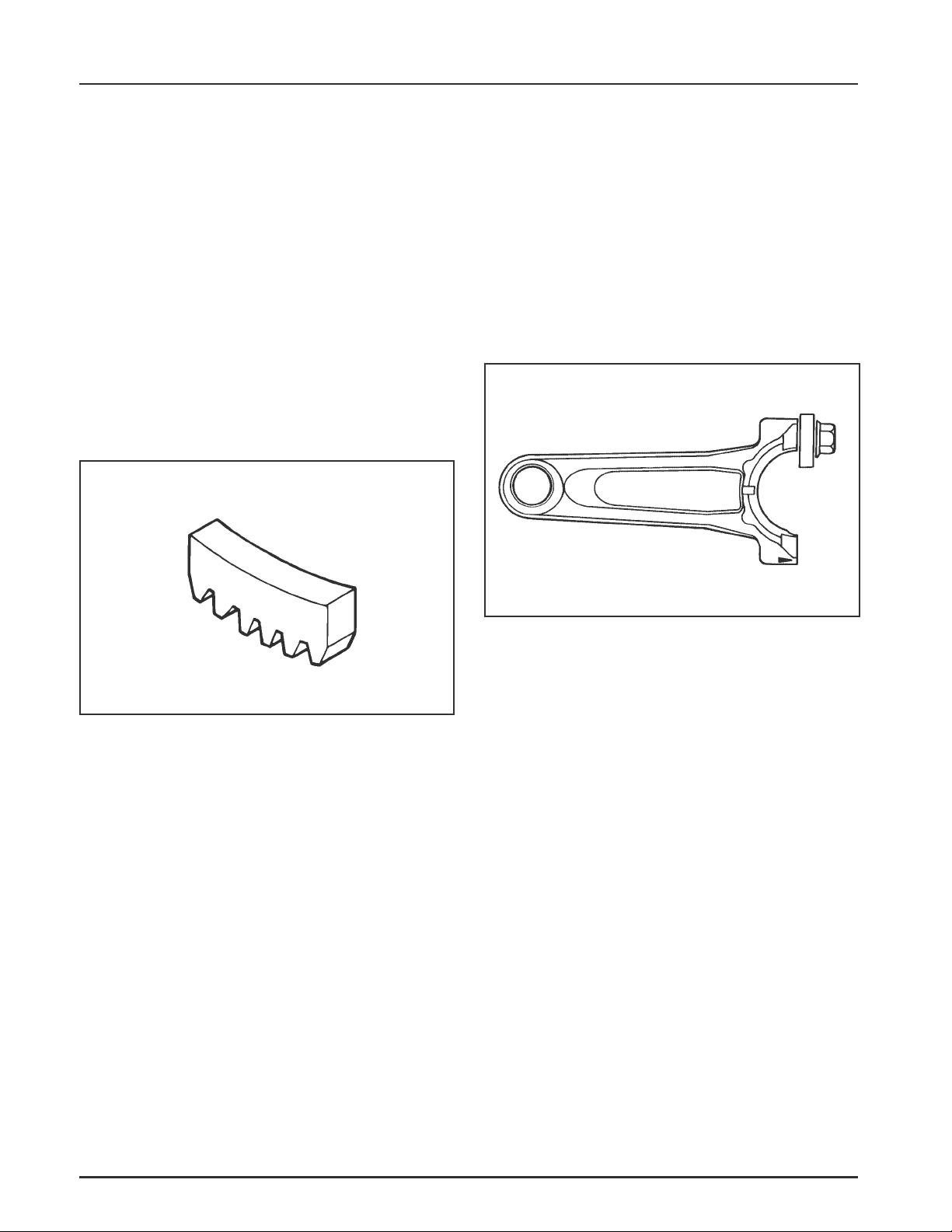
Special Tools You Can Make
Flywheel Holding Tool
A flywheel holding tool can be made out of an old
junk flywheel ring gear as shown in Figure 2-1, and
used in place of a strap wrench.
1. Using an abrasive cut-off wheel, cut out a six
tooth segment of the ring gear as shown.
2. Grind off any burrs or sharp edges.
3. Invert the segment and place it between the
ignition bosses on the crankcase so that the tool
teeth engage the flywheel ring gear teeth. The
bosses will lock the tool and flywheel in
position for loosening, tightening or removing
with a puller.
2. Remove the studs of a Posi-Lock rod or grind off
the aligning steps of a Command rod, so the joint
surface is flat.
3. Find a 1 in. long capscrew with the correct
thread size to match the threads in the
connecting rod.
4. Use a flat washer with the correct I.D. to slip on
the capscrew and approximately 1” O.D. (Kohler
Part No. 12 468 05-S). Assemble the capscrew
and washer to the joint surface of the rod, as
shown in Figure 2-2.
Figure 2-1. Flywheel Holding Tool.
Rocker Arm/Crankshaft Tool
A spanner wrench to lift the rocker arms or turn the
crankshaft may be made out of an old junk connecting
rod.
1. Find a used connecting rod from a 10 HP or
larger engine. Remove and discard the rod cap.
Figure 2-2. Rocker Arm/Crankshaf t T ool.
2.4
Page 20

Section 3
Troubleshooting
Section 3
Troubleshooting
Troubleshooting Guide
When troubles occur, be sure to check the simple
causes which, at first, may seem too obvious to be
considered. For example, a starting problem could be
caused by an empty fuel tank.
Some common causes of engine trouble are listed
below. Use these to locate the causing factors.
Engine Cranks But Will Not Start
1. Empty fuel tank.
2. Fuel shut-off valve closed.
3. Dirt or water in the fuel system.
4. Clogged fuel line.
5. Spark plug lead disconnected.
6. Key switch or kill switch in off position.
7. Faulty spark plug.
8. Faulty ignition module.
9. Choke not closing.
10. Faulty oil sending unit.
Engine Start s But Does Not Keep Running
1. Restricted fuel tank vent.
2. Dirt or water in the fuel system.
3. Faulty choke or throttle controls/cable.
4. Loose wires or connections that short the kill
terminal of ignition module to ground.
5. Faulty cylinder head gasket.
6. Faulty fuel pump.
7. Faulty carburetor.
8. Faulty fuel pump.
Engines Start s Hard
1. Hydrostatic transmission not in neutral/PTO
drive is engaged.
2. Dirt or water in the fuel system.
3. Clogged fuel line.
4. Loose or faulty wires or connections.
5. Faulty choke or throttle controls/cables.
6. Faulty spark plug.
7. Low compression.
8. Faulty Automatic Compression Release (ACR)
mechanism.
Engine Will Not Crank
1. Hydrostatic transmission not in neutral/PTO
drive is engaged.
2. Battery is discharged.
3. Safety interlock switch is engaged.
4. Loose or faulty wires or connections.
5. Faulty key switch or ignition switch.
6. Faulty electric starter/starter solenoid.
7. Retractable starter not engaging in drive cup.
8. Seized internal engine components.
Engine Runs But Misses
1. Dirt or water in the fuel system.
2. Spark plug lead disconnected.
3. Loose wires or connections that intermittently
short the kill terminal of ignition module to
ground.
4. Engine overheated.
5. Faulty ignition module.
Engine Will Not Idle
1. Restricted fuel tank cap vent.
2. Dirt or water in the fuel system.
3. Faulty spark plug.
4. Idle fuel adjusting needle improperly set.
5. Idle speed adjusting screw improperly set.
6. Low compression.
7. Stale fuel and/or gum in carburetor.
Engine Overheats
1. Air intake or grass screen, cooling fins, or cooling
shrouds clogged.
2. Excessive engine load.
3. Low crankcase oil level.
4. High crankcase oil level.
5. Faulty carburetor.
6. Lean fuel condition.
7. Restricted exhaust.
3
3.1
Page 21

Section 3
Troubleshooting
Engine Knocks
1. Excessive engine load.
2. Low crankcase oil level.
3. Old or improper fuel.
4. Internal wear or damage.
Engine Loses Power
1. Low crankcase oil level.
2. High crankcase oil level.
3. Dirty air cleaner element.
4. Dirt or water in the fuel system.
5. Excessive engine load.
6. Engine overheated.
7. Faulty spark plug.
8. Low compression.
9. Exhaust restriction.
Engine Uses Excessive Amount Of Oil
1. Incorrect oil viscosity/type.
2. Crankcase overfilled.
3. Clogged or improperly assembled breather.
4. Worn or broken piston rings.
5. Worn cylinder bore.
6. Worn valve stems or valve guides.
External Engine Inspection
Before cleaning or disassembling the engine, make a
thorough inspection of its external appearance and
condition. This inspection can give clues to what
might be found inside the engine (and the cause)
when it is disassembled.
• Check for buildup of dirt and debris on the
crankcase, cooling fins, grass screen and other
external surfaces. Dirt or debris on these areas are
causes of overheating.
• Check for obvious fuel and oil leaks, and
damaged components. Excessive oil leakage can
indicate a clogged or improperly assembled
breather, worn or damaged seals and gaskets, or
loose or improperly torqued fasteners.
• Check the air cleaner cover and base for damage
or indications of improper fit and seal.
• Check the air cleaner element. Look for holes,
tears, cracked or damaged sealing surfaces, or
other damage that could allow unfiltered air into
the engine. Also note if the element is dirty or
clogged. These could indicate that the engine has
been underserviced.
• Check the carburetor throat for dirt. Dirt in the
throat is further indication that the air cleaner is
not functioning properly.
• Check that the oil level is within the operating
range on the dipstick, or if it is low or overfilled.
• Check the condition of the oil. Drain the oil into a
container - the oil should flow freely. Check for
metal chips and other foreign particles.
Sludge is a natural by-product of combustion; a
small accumulation is normal. Excessive sludge
formation could indicate the oil has not been
changed at the recommended intervals, the
incorrect type or weight of oil was used, overrich
carburetion, and weak ignition, to name a few.
Cleaning the Engine
After inspecting the external condition of the engine,
clean the engine thoroughly before disassembling it.
Also clean individual components as the engine is
disassembled. Only clean parts can be accurately
inspected and gauged for wear or damage. There are
many commercially available cleaners that will
quickly remove grease, oil, and grime from engine
parts. When such a cleaner is used, follow the
manufacturer’s instructions and safety precautions
carefully.
Make sure all traces of the cleaner are removed before
the engine is reassembled and placed into operation.
Even small amounts of these cleaners can quickly
break down the lubricating properties of engine oil.
3.2
Page 22

Section 3
Troubleshooting
Basic Engine Tests
Crankcase Vacuum Test
A partial vacuum should be present in the crankcase
when the engine is operating at normal temperatures.
Pressure in the crankcase (normally caused by a
clogged or improperly-assembled breather) can cause
oil to be forced out at oil seals, gaskets, or other
available spots.
Crankcase vacuum is best measured with a water
manometer or vacuum/pressure test gauge. See
Section 2. Complete instructions are provided with the
testers.
Test the crankcase vacuum with the manometer as
follows:
1. Insert the rubber stopper into the oil fill hole. Be
sure the pinch clamp is installed on the hose and
use the tapered adapters to connect the hose
between the stopper and one of the manometer
tubes. Leave the other tube open to the
atmosphere. Check that the water level in the
manometer is at the "0" line. Make sure the pinch
clamp is closed.
2. Start the engine and run at no-load, high idle
speed (3200 to 3750 RPM).
3. Open the clamp and note the water level in the
tube.
The level in the engine side should be a minimum
of 10.2 cm (4 in.) above the level in the open side.
If the level in the engine side is the same as the
open side (no vacuum), or the level in the engine
side is lower than the level in the open side
(pressure), check for the conditions in the table
below.
4. Close the shut-off clamp before stopping the
engine.
To perform the test with the vacuum/pressure
gauge, insert the stopper as in step 1. Insert the
barbed gauge fitting into the hole in the stopper.
Be sure the gauge needle is at "0". Run the engine,
as in step 2, and observe the gauge reading.
Needle movement to the left of "0" is a vacuum,
and movement to the right indicates a pressure.
3
Incorrect Vacuum in Crankcase
Possible Cause
1. Crankcase breather clogged or inoperative.
2. Seals and/or gaskets leaking. Loose or improperly
torqued fasteners.
3. Piston blowby or leaky valves. Confirm with
cylinder leakdown test.
4. Restricted exhaust.
Solution
1. Disassemble breather, clean parts thoroughly,
reassemble, and recheck pressure.
2. Replace all worn or damaged seals and gaskets.
Make sure all fasteners are tightened securely. Use
appropriate torque values and sequences when
necessary.
3. Recondition piston, rings, cylinder bore, valves,
and valve guides.
4. Repair/replace restricted muffler/exhaust system.
3.3
Page 23

Section 3
Troubleshooting
Compression T est
These engines are equipped with an automatic
compression release (ACR) mechanism. Because of the
ACR mechanism, it is difficult to obtain an accurate
compression reading. As an alternate, use the
leakdown test described below.
Cylinder Leakdown T est
A cylinder leakdown test can be a valuable alternative
to a compression test. By pressurizing the combustion
chamber from an external air source you can
determine if the valves or rings are leaking, and how
badly.
The tester is a relatively simple, inexpensive leakdown
tester for small engines. The tester includes a quick
disconnect for attaching the adapter hose and a
holding tool.
Leakdown T est Instructions
1. Run engine for 3-5 minutes to warm it up.
2. Remove spark plug and air filter from engine.
3. Rotate crankshaft until piston is at top dead
center of compression stroke. You will need to
hold the engine in this position while testing. The
holding tool supplied with the tester can be used
if the PTO end of the crankshaft is accessible.
Slide the holding tool onto the crankshaft. See
TT-364-A. Install a 3/8" breaker bar into the
square hole of the holding tool, so it is
perpendicular to both the holding tool and
crankshaft PTO.
If the flywheel end is more accessible, you can
use a breaker bar and socket on the flywheel nut/
screw to hold it in position. You may need an
assistant to hold the breaker bar during testing. If
the engine is mounted in a piece of equipment,
you may be able to hold it by clamping or
wedging a driven component. Just be certain that
the engine cannot rotate off of TDC in either
direction.
4. Install the adapter into the spark plug hole, but
do not attach it to the tester at this time.
5. Connect an adequate air source of at least 50 psi
to the tester.
6. Turn the regulator knob in the increase
(clockwise) direction until the gauge needle is in
the yellow “set” area at the low end of the scale.
7. Connect tester quick-disconnect to the adapter
hose while firmly holding the engine at TDC.
Note the gauge reading and listen for escaping air
at the carburetor intake, exhaust outlet, and
crankcase breather.
8. Check your test results against the table below:
Leakdown Test Results
Air escaping from crankcase breather .............................................. Defective rings or worn cylinder walls.
Air escaping from exhaust system ..................................................... Defective exhaust valve.
Air escaping from carburetor .............................................................. Defective intake valve.
Gauge reading in “low” (green) zone................................................ Piston rings and cylinder in good condition.
Gauge reading in “moderate” (yellow) zone.................................... Engine is still usable, but there is some wear
present. Customer should start planning for
overhaul or replacement.
Gauge reading in “high” (red) zone .................................................. Rings and/or cylinder have considerable wear.
Engine should be reconditioned or replaced.
3.4
Page 24
Air Intake and Air Cleaner System
Section 4
Air Cleaner and Air Intake System
Section 4
Air Cleaner
General
These engines are equipped with a replaceable, highdensity paper air cleaner element. Most are also
equipped with an oiled-foam precleaner which
surrounds the paper element. See Figures 4-1 and 4-2.
Air Cleaner
Cover Knob
Air Cleaner
Cover
Figure 4-1. Air Cleaner Housing Components.
Air Cleaner Base
Element Cover
Wing Nut
Service
Check the air cleaner daily or before starting the
engine. Check for and correct any buildup of dirt and
debris, along with loose or damaged components.
NOTE: Operating the engine with loose or damaged
air cleaner components could allow
unfiltered air into the engine, causing
premature wear and failure.
Precleaner Service
If so equipped, wash and reoil the precleaner every 25
hours of operation (more often under extremely dusty
or dirty conditions).
To service the precleaner, perform the following steps:
1. Loosen the cover retaining knob and remove the
cover.
2. Remove the foam precleaner from the paper air
cleaner element.
3. Wash the precleaner in warm water with
detergent. Rinse the precleaner thoroughly until
all traces of detergent are eliminated. Squeeze out
excess water (do not wring). Allow the precleaner
to air dry.
4
Paper Element
Foam Precleaner
Figure 4-2. Air Cleaner Element s.
Element
Cover
4. Saturate the precleaner with new engine oil.
Squeeze out all excess oil.
5. Reinstall the precleaner over the paper air cleaner
element.
6. Reinstall the air cleaner cover. Secure the cover
with the retaining knob.
4.1
Page 25

Section 4
Air Cleaner and Air Intake System
Paper Element Service
Every 100 hours of operation (more often under
extremely dusty or dirty conditions), replace the paper
element. Follow these steps:
1. Loosen the cover retaining knob and remove the
cover.
2. Remove the wing nut, element cover, and air
cleaner element.
3. Remove the precleaner (if so equipped) from the
paper element. Service the precleaner as
described in “Precleaner Service”.
4. Do not wash the paper element or use
pressurized air, as this will damage the element.
Replace a dirty, bent, or damaged element with a
genuine Kohler element. Handle new elements
carefully; do not use if the sealing surfaces are
bent or damaged.
5. Check the rubber sleeve seal for any damage or
deterioration. Replace as necessary. A new seal
comes packed with each replacement element.
2. Remove the wing nut, element cover, and air
cleaner element.
3. If so equipped, remove the precleaner from the
paper element.
4. Disconnect the breather hose from the valve
cover.
5. Remove the air cleaner base mounting nuts, air
cleaner base, and gasket.
6. If necessary, remove the self-tapping screws and
elbow from air cleaner base.
Reassembly
The following procedure is for complete assembly of
all air cleaner components.
1. Install the elbow and self-tapping screws to air
cleaner base.
2. Install the gasket, air cleaner base, and base
mounting nuts. Torque the nuts to 9.9 N·m
(88 in. lb.).
6. Reinstall the paper element, precleaner, element
cover, and wing nut.
7. Reinstall the air cleaner cover and secure with the
two latches or the retaining knob.
Inspect Air Cleaner Components
Whenever the air cleaner cover is removed, or the
paper element or precleaner are serviced, check the
following areas/components:
Air Cleaner Base - Make sure the base is secured and
not cracked or damaged. Since the air cleaner base and
carburetor are secured to the intake port with
common hardware, it is extremely important that the
nuts securing these components are tight at all times.
Breather Tube - Make sure the breather tube is
installed to both the air cleaner base and valve cover.
Disassembly
The following procedure is for complete disassembly
of all air cleaner components.
1. Loosen the air cleaner cover retaining knob and
remove the air cleaner cover.
3. Connect the breather hose to the valve cover (and
air cleaner base). Secure with hose clamps.
4. If so equipped, install the precleaner (washed and
oiled) over the paper element.
5. Install the air cleaner element, element cover, and
wing nut.
6. Install the air cleaner cover and air cleaner cover
retaining knob. Tighten the knob securely.
Air Intake/Cooling System
To ensure proper cooling, make sure the grass screen,
cooling fins, and other external surfaces of the engine
are kept clean at all times.
Every 100 hours of operation (more often under
extremely dusty or dirty conditions), remove the
blower housing and other cooling shrouds. Clean the
cooling fins and external surfaces as necessary. Make
sure the cooling shrouds are reinstalled.
NOTE: Operating the engine with a blocked grass
screen, dirty or plugged cooling fins, and/or
cooling shrouds removed, will cause engine
damage due to overheating.
4.2
Page 26
Fuel System and Governor
Section 5
Fuel System and Governor
Section 5
Description
WARNING: Explosive Fuel!
Gasoline is extremely flammable and its vapors can explode
if ignited. Store gasoline only in approved containers, in
well ventilated, unoccupied buildings, away from sparks or
flames. Do not fill the fuel tank while the engine is hot or
running, since spilled fuel could ignite if it comes in contact
with hot parts or sparks from ignition. Do not start the
engine near spilled fuel. Never use gasoline as a cleaning
agent.
Fuel System Components
The typical fuel system and related components
include the following:
• Fuel Tank • Fuel Lines
• In-Line Fuel Filter • Fuel Pump
• Carburetor
Operation
The fuel from the tank is moved through the in-line
filter and fuel lines by the fuel pump. On engines not
equipped with a fuel pump, the fuel tank outlet is
located above the carburetor inlet; gravity moves the
fuel.
Fuel then enters the carburetor float bowl and is
moved into the carburetor body. There, the fuel is
mixed with air. This fuel-air mixture is then burned
in the engine combustion chamber.
Fuel Filter
Most engines are equipped with an in-line fuel filter.
Periodically inspect the filter and replace with a
genuine Kohler filter every 200 operating hours.
Fuel Line
In compliance with CARB Tier III Emission
Regulations, these engines with a Family
identification number beginning with 6 or greater
(see Figure 5-1), must use Low Permeation SAE 30 R7
rated fuel line; certified to meet CARB requirements.
Standard fuel line may not be used. Order
replacement hose by part number through a Kohler
Engine Service Dealer.
IMPORTANT ENGINE INFORMATION
THIS ENGINE MEETS U.S. EPA AND CA 2005 AND
LATER AND EC ST AGE II (SN:4) EMISSION REGS
FOR SI SMALL OFF–ROAD ENGINES
FAMILY 6 KHXS.XXXX PH
TYPE APP
DISPL. (CC)
MODEL NO.
SPEC. NO.
SERIAL NO.
BUILD DA TE
OEM PROD. NO.
EMISSION COMPLIANCE PERIOD:
EPA: CARB:
CERTIFIED ON:
REFER TO OWNER'S MANUAL FOR HP RATING,
SAFETY , MAINTENANCE AND ADJUSTMENTS
1-800-544-2444 www.kohlerengines.com
KOHLER CO. KOHLER, WISCONSIN USA
N11236
5
Figure 5-1. "Family" Number Location.
5.1
Page 27
Section 5
Fuel System and Governor
Fuel System T ests
When the engine starts hard, or turns over but will not start, it is possible that the problem is in the fuel
system. To find out if the fuel system is causing the problem, perform the following tests.
Troubleshooting - Fuel System Related Causes
T e st Conclusion
1. Check for the following:
a. Make sure the fuel tank contains clean, fresh,
proper fuel.
b. Make sure the vent in fuel tank cap is open.
c. Make sure the fuel valve is open.
2. Check for fuel in the combustion chamber.
a. Disconnect and ground spark plug lead.
b. Close the choke on the carburetor.
c. Crank the engine several times.
d. Remove the spark plug and check for fuel at
the tip.
3. Check for fuel flow from the tank to the fuel pump.
a. Remove the fuel line from the inlet fitting of
fuel pump.
b. Hold the line below the bottom of the tank.
Open the shut-off valve (if so equipped) and
observe flow.
4. Check the operation of fuel pump.
a. Remove the fuel line from the inlet fitting of
carburetor.
b. Crank the engine several times and observe
flow.
Fuel Pump
2. If there is fuel at the tip of the spark plug, fuel is
reaching the combustion chamber.
If there is no fuel at the tip of the spark plug,
check for fuel flow from the fuel tank. (Test 3)
3. If fuel does flow from the line, check for faulty
fuel pump. (Test 4)
If fuel does not flow from the line, check for
clogged fuel tank vent, fuel pick-up screen, in-line
filter, shut-off valve, and fuel lines.
4. If fuel does flow from the line, check for faulty
carburetor. (Refer to the “Carburetor” portions of
this section.)
If fuel does not flow from the line, check for
clogged fuel line. If the fuel line is unobstructed,
the fuel pump is faulty and must be replaced.
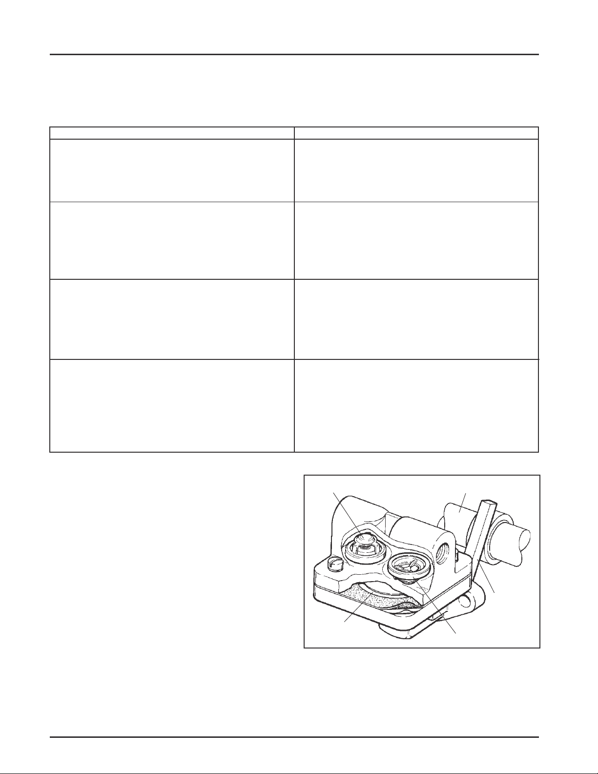
Outlet Check Valve
Camshaft
General
Most engines are equipped with an optional
mechanically operated fuel pump. On applications
using a gravity feed fuel system, the fuel pump
mounting pad is covered with a metal plate.
The fuel pump body is constructed of nylon. The
nylon body insulates the fuel from the engine
crankcase. This prevents the fuel from vaporizing
inside the pump.
Operation
The mechanical pump is operated by a lever which
rides on the engine camshaft. The lever transmits a
pumping action to the diaphragm inside the pump
body. On the downward stroke of the diaphragm, fuel
is drawn in through the inlet check valve. On the
upward stroke of the diaphragm, fuel is forced out
through the outlet check valve. See Figure 5-2.
5.2
Diaphragm
Figure 5-2. Cutaway - Typical Fuel Pump.
Inlet Check Valve
Fuel Pump
Lever
Page 28
Replacing the Fuel Pump
Nonmetallic fuel pumps are not serviceable and must
be replaced when faulty. Replacement pumps are
available in kits that include the pump, fittings, and
mounting gasket.
1. Disconnect the fuel lines from the inlet and outlet
fittings.
2. Remove the hex flange screws, fuel pump, and
gasket.
3. If necessary, remove the fittings from the pump
body.
Section 5
Fuel System and Governor
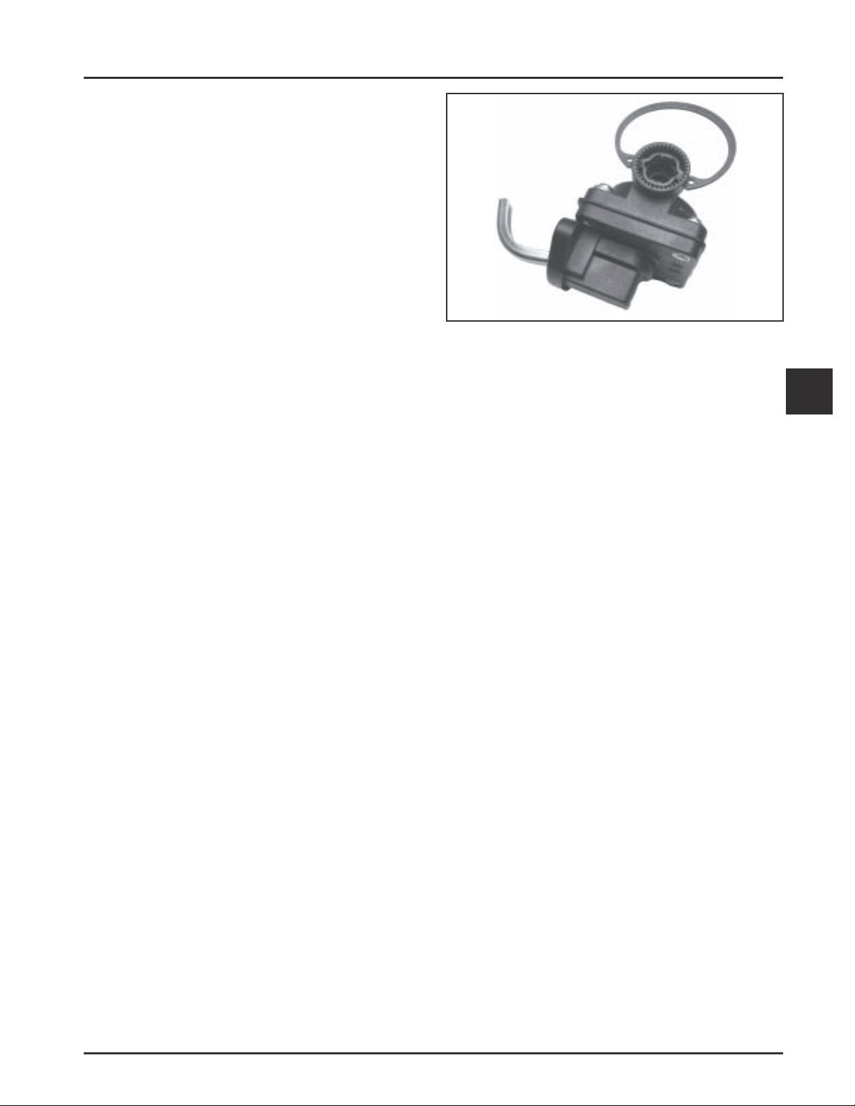
Figure 5-3.
4. Install Fittings
Threaded Fittings
a. Apply a small amount of Permatex® Aviation
Perm-a-Gasket (or equivalent) gasolineresistant thread sealant to the threads of
fittings. Turn the fittings into the pump 5 full
turns; continue turning the fittings in the
same direction until the desired position is
reached.
Lock-in Fittings
The inlet and outlet hose fittings must be
installed into the fuel pump prior to mounting.
The pump housing incorporates a special locking
feature to retain the fittings. The release tabs
must be depressed when the fittings are installed
or removed, to avoid damage to the fitting ORings and a potential fuel leak. Do not attempt to
install or force the fittings into place without
first depressing the tabs. There is a snap ring
included with the new fuel pump kit that will
serve as a tool for this purpose.
a. Note the direction arrows molded into the
pump housing and position the snap ring so
the ends depress the two square release tabs
at the inlet end. See Figure 5-3.
b. Lubricate the O-Ring on each fitting with oil.
c. Insert the 90° fitting until the toothed flange is
just outside of the pump body. Rotate the
fitting to the desired orientation and then
apply pressure to seat/snap it into the
housing. The flange face will be flush with the
end of the housing.
d. Transfer the snap ring to the opposite end and
repeat the sequence to install the straight
fitting. Remove the snap ring.
5. Clean off any remaining gasket material from the
fuel pump mounting surface. Refer to the pump
installation instructions to determine if the extra
spacer and gasket are required to mount the new
pump. Install new gasket, fuel pump, and hex
flange screws.
NOTE: Make sure the fuel pump lever is
positioned to the RIGHT of the camshaft
(when looking at fuel pump mounting
pad). Damage to the fuel pump, and
subsequent severe engine damage could
result if the lever is positioned to the left
of the camshaft.
Torque the hex flange screws as follows:
5
Into new holes–9.0 N·m (80 in. lb.).
Into used holes–4.2-5.1 N·m (37-45 in. lb.).
6. Connect the fuel lines to the inlet and outlet
fittings.
5.3
Page 29
Section 5
Fuel System and Governor
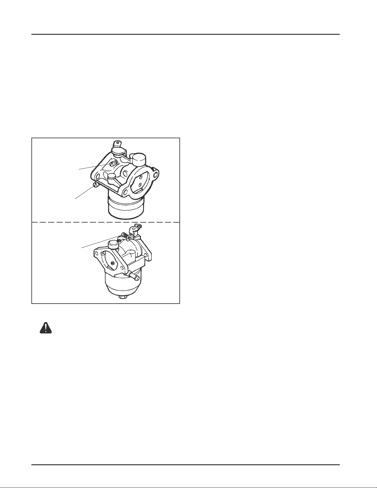
Carburetors
These engines, based upon when produced, are
equipped with either an adjustable main jet
carburetor, or an emission compliant fixed jet
carburetor manufactured be Walbro or Nikki. See
Figure 5-4.
Walbro carburetors have a low idle speed screw and a
low idle fuel adjusting needle. Nikki carburetors only
have a low idle speed screw. Certified carburetors will
have fixed idle fuel or a limiter cap on the idle fuel
adjusting needle.
Walbro
Low Idle Speed
Adjustment Screw
Low Idle Fuel
Adjustment Needle
Nikki
Low Idle Speed
Adjustment Screw
Troubleshooting
If engine troubles are experienced that appear to be
fuel system related, check the following areas before
adjusting or disassembling the carburetor.
• Make sure the fuel tank is filled with clean, fresh
gasoline.
• Make sure the fuel tank cap vent is not blocked
and that it is operating properly.
• Make sure fuel is reaching the carburetor. This
includes checking the fuel shut-off valve, fuel
tank filter screen, in-line fuel filter, fuel lines, and
fuel pump for restrictions or faulty components
as necessary.
• Make sure the air cleaner base and carburetor is
securely fastened to the engine using gaskets in
good condition.
• Make sure the air cleaner element is clean and all
air cleaner components are fastened securely.
• Make sure the ignition system, governor system,
exhaust system, and throttle and choke controls
are operating properly.
If the engine is still hard-to-start, runs roughly, or
stalls at low idle speed, it may be necessary to adjust
or service the carburetor.
Figure 5-4. Carburetor Adjustment.
WARNING: Explosive Fuel!
Gasoline is extremely flammable and its vapors can explode
if ignited. Store gasoline only in approved containers, in
well ventilated, unoccupied buildings, away from sparks or
flames. Do not fill the fuel tank while the engine is hot or
running, since spilled fuel could ignite if it comes in contact
with hot parts or sparks from ignition. Do not start the
engine near spilled fuel. Never use gasoline as a cleaning
agent.
5.4
Page 30

Conditi on Possible Cause/Probable Remedy
1. Engine starts hard, or
runs roughly or stalls at
idle speed.
Section 5
Fuel System and Governor
1. Low idle fuel mixture or speed are improperly adjusted. Adjust the low idle
speed screw, then adjust the low idle fuel needle (adjustable carburetors), or
clean the carburetor as required (fixed jet carburetors).
2. Engine runs rich
(indicated by black,
sooty exhaust smoke,
misfiring, loss of speed
and power, governor
hunting, or excessive
throttle opening).
3. Engine runs lean
(indicated by misfiring,
loss of speed and power,
governor hunting, or
excessive throttle
opening).
2a. Choke partially closed during operation. Check the choke lever/linkage/self-
relieving mechanism to ensure choke is operating properly.
b. Low idle fuel mixture is incorrect. Adjust low idle speed screw, then adjust
low idle fuel needle (adjustable carburetors), or clean the carburetor
passages as required (fixed jet carburetors).
c. Float level is set too high. With fuel bowl removed and carburetor inverted,
the exposed surface of float must be parallel with the bowl gasket surface of
the carburetor body.
d. Dirt under the fuel inlet needle. Remove needle; clean needle and seat and
blow with compressed air.
e. Air filter dirty or restricted.
f. Bowl vent or air bleeds plugged. Remove fuel bowl, low idle fuel adjusting
needle, (not on all models), and welch plugs. Clean vent, ports, passages and
air bleeds. Blow out all passages with clean, compressed air.
g. Leaky, cracked, or damaged float. Submerge float to check for leaks.
3a. Low idle fuel mixture incorrect. Adjust the low idle speed screw, then adjust
low idle fuel needle (adjustable carburetors), or clean the carburetor
passages as required (fixed jet carburetors).
b. Float level is set too low. With fuel bowl removed and carburetor inverted,
the exposed surface of float must be parallel with the bowl gasket surface of
the carburetor body.
5
4. Fuel leaks from
carburetor.
c. Idle holes plugged; dirt in fuel delivery channels. Remove fuel bowl, low idle
fuel adjusting needle (not on all models) and welch plugs. Clean main fuel jet
and all passages; blow out cleaned compressed air.
4a. Float level set too high. See Remedy 2c.
b. Dirt under fuel inlet needle. See Remedy 2d.
c. Bowl vent plugged. Remove fuel bowl and clean bowl vent. Blow out with
compressed air.
d. Float is cracked or damaged. Replace float.
e. Bowl gasket damaged. Replace gasket.
f. Bowl screw or shut-off solenoid loose or gasket damaged. Tighten/torque
screw to specifications.
5.5
Page 31

Section 5
Fuel System and Governor
Adjustment
NOTE: Carburetor adjustments should be made
only after the engine has warmed up.
Emission Compliant Non-Adjustable Carburetors
In compliance with current government emission
standards, carburetors on later production engines
are calibrated to deliver the correct fuel-to-air
mixture to the engine under all operating conditions,
without external adjustments, except for low idle
speed (RPM). See Figure 5-5.
Figure 5-5. Emission Compliant Non-Adjustable.
If running performance and troubleshooting indicates
a problem which cannot be rectified by external
means, or adjustment of the low idle speed (RPM)
setting, carburetor disassembly and cleaning may be
required. The basic disassembly and service
procedures for these carburetors remain the same.
Refer to pages 5.6 thru 5.10 as required.
Adjust Carburetor
Low idle speed (RPM) setting:
Low Idle Fuel Needle with Limiter Cap Adjustment:
Some emission compliant carburetors have a limiter
cap on the low idle fuel adjustment screw. Adjustment
is limited to the range established by the cap. Do not
attempt to remove or adjust beyond the limits. See
Figure 5-6.
Lean
Adjust T o
Midpoint
Rich
Figure 5-6.
Adjustable Carburetors
The carburetor on these engines is designed to deliver
the correct fuel-to-air mixture to the engine under all
operating conditions. Adjustable model carburetors
contain adjustment screws for the high and idle
mixtures. If the engine is hard starting, runs roughly
or stalls at low idle speed, it may be necessary to
adjust, clean or service the carburetor.
Low Idle Speed
Adjusting Screw
1. Place the throttle control into the "idle" or "slow"
position. Set the low idle speed to 1500 RPM
(±75RPM) by turning the low idle speed adjusting
screw in or out. Check the speed using a
tachometer.
NOTE: The actual low idle speed depends on
the application - refer to equipment
manufacture's recommendations. The
recommended low idle speed for basic
engines is 1500 RPM.
5.6
Low Idle
Fuel
Adjusting
Needle
Figure 5-7. Adjustable Main Jet Carburetor.
High Speed
(RPM)
Adjusting
Screw
Page 32

Section 5
Fuel System and Governor
Adjust Carburetor (Adjustable Main Jet)
1. With the engine stopped turn the low and high
idle fuel adjusting needles in (clockwise) until
they bottom lightly.
NOTE: The tip of the idle fuel and high idle fuel
adjusting needles are tapered to critical
dimensions. Damage to the needles and
the seats in carburetor body will result if
the needles are forced.
2. Preliminary Settings: Turn the adjusting needles
out (counterclockwise) from lightly bottomed to
the positions shown in the chart.
Adjust Carburetors Only
Turns
CH11
Idle
High Speed
3. Start the engine and run at half-throttle for 5 to
10 minutes to warm up. The engine must be
warm before making final settings. Check that
the throttle and choke plates can fully open.
1-1/4
CH12.5 CH14
1-1/4
1-1/2
1-3/4
1-1/41-1/2
5. Low Idle Speed Setting: Place the throttle control
into the “idle” or “slow” position. Set the low
idle speed to 1500 RPM *(± 75 RPM) by turning
the low idle speed adjusting screw in or out.
Check the speed using a tachometer.
*NOTE: The actual low idle speed depends on
the application - refer to equipment
manufacturer’s recommendations. The
recommended low idle speed for basic
engines is 1500 RPM. To ensure best
results when setting the low idle fuel
needle the low idle speed should not
exceed 1500 RPM (± 75 RPM).
6. Low Idle Fuel Needle Setting: Place the throttle
into the “idle” or “slow” position. Turn the low
idle fuel adjusting needle in (slowly) until engine
speed decreases, and then back out
approximately 1/8 to 1/4 turn to obtain the best
low speed performance.
7. Recheck the idle speed using a tachometer.
Readjust the speed as necessary.
5
4. High Speed Fuel Needle Setting: Place the
throttle into the “fast” position. If possible place
the engine under load. Turn the high idle fuel
adjusting needle in (slowly) until engine speed
decreases and then back out approximately 1/4
turn for best high-speed performance.
5.7
Page 33

Section 5
Fuel System and Governor
Disassembly
1. Remove the power screw, needle and spring,
main jet, power screw gasket and fuel bowl.
2. Remove the bowl gasket, float shaft, float, and
fuel inlet needle.
Dust Seal
Throttle Plate
Screw(s)
Throttle
Plate
3. Remove the low idle fuel adjusting needle and
spring, from the carburetor body, if not capped or
containing an adjustment limiter. Remove the idle
speed adjusting screw and spring.
Further disassembly to remove the welch plug,
fuel inlet seat, throttle plate and shaft, and choke
plate and shaft is recommended only if these
parts are to be cleaned or replaced.
Throttle Lever and Shaft
Choke Lever and Shaft
Choke Return Spring
Low Idle Speed Adjusting
Screw and Spring
Low Idle Fuel Adjusting
Needle and Spring
Inset
Fuel Shutoff
Solenoid Installed
Figure 5-8. Adjustable Main Jet Carburetor - Exploded View.
Fuel Inlet
Seat
Fuel Inlet
Needle
Choke Plate
Float
Float Shaft
Bowl Gasket
Fuel Bowl
Bowl Retaining Screw
Bowl Retaining Screw
5.8
Page 34

Welch Plug Removal
In order to clean the “off-idle” ports and bowl vent
thoroughly, remove the welch plug covering these
areas.
Use Tool No. KLR1018 and the following procedure to
remove the welch plug. See Figure 5-9.
1. Pierce the welch plug with the tip of the tool.
NOTE: To prevent damage to the carburetor, do
not allow the tool to strike the carburetor
body.
Section 5
Fuel System and Governor
Choke Plate
Carburetor Body
2. Pry out the welch plug with the tip of the tool.
Tool No. KLR1018
Do Not Allow Tip
T o S trike
Carburetor Body
Figure 5-9. Removing Welch Plug.
Fuel Inlet Seat Removal
To remove the fuel inlet seat, pull it out of the
carburetor body using a screw, drill bit, or similar tool.
NOTE: Always install a new fuel inlet seat. Do not
reinstall a seat that has been removed.
Choke Shaft Removal
1. Because the edges of the choke plate are beveled,
mark the choke plate and carburetor body to
ensure correct reassembly. See Figure 5-10.
Also take note of the choke plate position in bore,
and the position of the choke lever and choke
return spring.
Pierce Plug
With Tip
Welch Plug
Pry Out Plug
Figure 5-10. Marking Choke Plate and Carburetor
Body .
2. Grasp the choke plate with a pliers. Pull it out of
the slot in the choke shaft. See Figure 5-11.
Choke Plate
Figure 5-11. Removing Choke Plate.
3. Remove the choke shaft and choke return spring.
Throttle Shaft Removal
1. Because the edges of the throttle plate are
beveled, mark the throttle plate and carburetor
body to ensure correct reassembly.
Also take note of the throttle plate position in
bore, and the position of the throttle lever.
2. Carefully and slowly remove the screws securing
the throttle plate to the throttle shaft. Remove the
throttle plate.
5
3. File off any burrs which may have been left on
the throttle shaft when the screws were removed.
Do this before removing the throttle shaft from
the carburetor body.
5.9
Page 35

Section 5
Fuel System and Governor
4. Remove the throttle lever/shaft assembly with
foam dust seal.
Cleaning
WARNING: Flammable Solvent s!
Carburetor cleaners and solvents are extremely flammable.
Keep sparks, flames, and other sources of ignition away
from the area. Follow the cleaner manufacturer’s warnings
and instructions on its proper and safe use. Never use
gasoline as a cleaning agent.
All parts should be cleaned thoroughly using a
carburetor cleaner (such as acetone). Make sure all
gum deposits are removed from the following areas:
• Carburetor body and bore; especially the areas
where the throttle plate, choke plate and shafts
are seated.
• Idle fuel and “off-idle” ports in carburetor bore,
power screw, bowl vent, and fuel inlet needle
and seat.
• Inspect the fuel inlet needle and seat for wear or
damage.
• Inspect the tip of the low idle fuel adjusting
needle and power screw needle for wear or
grooves.
• Inspect the throttle and choke shaft and plate
assemblies for wear or excessive play.
Repair
Always use new gaskets when servicing or
reinstalling carburetors. Repair kits are available
which include new gaskets and other components.
Always refer to the Parts Manual for the engine being
serviced to ensure the correct repair kits and
replacement parts are ordered.
Reassembly
Throttle Shaft Installation
1. Install the foam dust seal on the throttle shaft.
NOTE: These areas can be cleaned with a piece
of fine wire in addition to cleaners. Be
careful not to enlarge the ports, or break
the wire inside the ports. Blow out all
passages with compressed air.
• Float and float hinge.
• Fuel bowl.
• Throttle plate, choke plate, throttle shaft, and
choke shaft.
NOTE: Do not submerge the carburetor in cleaner or
solvent when fiber, rubber, or foam seals or
gaskets are installed. The cleaner may
damage these components.
Inspection
Carefully inspect all components and replace those
that are worn or damaged.
• Inspect the carburetor body for cracks, holes, and
other wear or damage.
2. Insert the throttle lever/shaft assembly into the
carburetor body. Position the cutout portion of
the shaft so it faces the carburetor mounting
flange.
3. Install the throttle plate to the throttle shaft. Make
sure the plate is positioned properly in the bore
as noted and marked during disassembly. Apply
Loctite® No. 609 to the threads of the throttle
plate retaining screws. Install the screws so they
are slightly loose.
Apply Pressure When
Tightening Screws
• Inspect the float for cracks, holes, and missing or
damaged float tabs. Check the float hinge and
shaft for wear or damage.
5.10
Figure 5-12. Installing the Throttle Lever/Shaft.
Page 36

Section 5
Fuel System and Governor
4. Apply finger pressure to the throttle lever/shaft
to keep it firmly seated against the pivot in the
carburetor body. Rotate the throttle shaft until the
throttle plate closes the bore around its entire
perimeter; then tighten the screws. See Figure
5-12.
5. Operate the throttle lever. Check for binding
between the throttle plate and carburetor bore.
Loosen the screws and adjust the throttle plate as
necessary.
Torque the screws to 0.9-1.4 N·m (8-12 in. lb.).
Choke Shaft Installation
1. Install the choke return spring to the choke shaft.
2. Insert the choke lever with return spring into the
carburetor body.
3. Rotate the choke lever approximately 1/2 turn
counterclockwise. Make sure the choke return
spring hooks on the carburetor body.
4. Position the choke plate as noted and marked
during disassembly. Insert the choke plate into
the slot in the choke shaft. Make sure the choke
shaft is locked between the tabs on the choke
plate.
Fuel Inlet Seat Installation
Press the fuel inlet seat into the bore in carburetor
body until it bottoms.
Welch Plug Installation
Use Tool KLR1019 and install new plugs as follows:
1. Position the carburetor body with the welch plug
cavity to the top.
2. Place a new welch plug into the cavity with the
raised surface up.
3. Use the end of the tool that is about the same
size as the plug and flatten the plug. Do not
force the plug below the surface of the cavity.
See Figure 5-13.
Tool KLR1019
New Welch Plug
Carburetor Body
Figure 5-13. Installing Welch Plug.
Carburetor Reassembly
1. Install the low idle speed adjusting screw and
spring.
2. Non-Emission Compliant Carburetors Only -
a. Install the low idle fuel adjusting needle and
spring. Turn the adjusting needle in (clock
wise) until it bottoms lightly.
NOTE: The tip of the idle fuel adjusting
needle is tapered to critical
dimensions. Damage to the needle
and the seat in carburetor body will
result if the needle is forced.
b. Turn the low idle fuel adjusting needle out
(counterclockwise) as specified in the
“Adjustment” portion of this section.
3. Attach the fuel inlet needle to the float. Lower the
float/needle into the carburetor body. See Figure
5-14.
4. Install the float shaft.
Float
5
4. After the plug is installed, seal it with glyptal (or
an equivalent sealant). Allow the sealant to dry.
NOTE: If a commercial sealant is not available,
fingernail polish can be used.
Fuel Inlet
Needle
Figure 5-14. Installing Float and Fuel Inlet Needle.
5.11
Page 37

Section 5
Fuel System and Governor
5. Install the bowl gasket, fuel bowl, bowl retainer
gasket, and bowl screw/shut-off solenoid/power
screw, as equipped. Torque to: 5.1-6.2 N·m
(45-55 in. lb.).
High Altitude Operation
When operating the engine at altitudes of 1830 m
(6000 ft.) and above, the main fuel mixture tends to
get overrich. An overrich mixture can cause
conditions such as black, sooty exhaust smoke,
misfiring, loss of speed and power, poor fuel economy,
and poor or slow governor response.
To compensate for the effects of high altitude, a special
high altitude main fuel jet can be installed. High
altitude jets are sold in kits which include the jet and
necessary gaskets. Refer to the parts manual for the
engine being serviced for the correct kit number.
Fuel Shut-Off Solenoid
Some gasoline fueled engines are equipped with the
optional fuel shutoff solenoid which is installed in
place of the bowl retaining screw or main jet (power)
screw, to eliminate backfiring when the engine is shut
down. If backfiring occurs on engines equipped with
this solenoid, check the battery first to insure that it is
not discharged or faulty. A minimum of 7.3 volts D.C.
is required to activate the solenoid. Also check to see
that the ground lead from the carburetor body is
properly connected to the carburetor mounting stud
or the plated (silver) baffle screw. If these check out,
the solenoid should be removed for bench testing.
Remember to shut off fuel and catch any fuel spilling
from the carburetor as the solenoid is removed.
4. With the switched 12 volt power supply "off",
insert a 1/4 male spade terminal into the
terminal end of the red power lead. Connect the
exposed terminal to the positive (+) power
supply lead/connection.
5. Turn "on" the power supply. If the pin of the
solenoid retracts the solenoid is good. Perform
test (switch off-on), a minimum of 6 times to
verify operating performance.
Self-Relieving Choke Service
On carburetors featuring the self-relieving choke, as
shown in cutaway of Figure 5-15, the choke plate is
secured to the choke shaft with two screws. On
carburetors without this feature, the choke plate fits
into a slot in the shaft. Use the following procedure to
replace the self-relieving choke components using
Choke Repair Kit No. 12 757 11 for gasoline
carburetors.
Dust Cap
Spring
Brass
Bushing
Stop Pin
Choke Valve
Screw
Choke Lever
Below is a simple test made with the engine off that
can determine if the solenoid is functioning properly.
Use a separate switched 12 volt power supply to test.
1. Shut off the fuel and remove the solenoid from
the carburetor. When the solenoid is loosened and
removed, gas will leak out of the carburetor. Have
a container ready to catch the fuel.
2. Blow/clean off solenoid using clean, compressed
air.
CAUTION
Do this test away from any fuel/vapors to prevent an
accident.
3. Attach a jumper wire with alligator clips between
the solenoid black ground lead and the ground
lead/location of the switched 12 volt power
supply.
5.12
Figure 5-15. Cutaway View Showing Self-Relieving
Choke Carburetor.
Removing Old Parts
1. Remove the black dust cover. This cover snaps on
and off.
2. Remove and discard the two screws fastening
the choke plate to the choke shaft.
3. Remove and discard the choke plate and choke
shaft from the carburetor.
Page 38

4. Remove the upper brass bushing using one of the
following procedures:
a. Use a slide hammer type bearing puller.
b. Use a #3 (for 5-32 dia. hole) screw extractor.
Secure extractor in a vise. Turn carburetor on
to the extractor. While pulling on the
carburetor, lightly tap the carburetor casting
with a hammer or use a size 12-28 tap if a #3
screw extractor is not available.
Installing Kit Parts
Section 5
Fuel System and Governor
WARNING: Prevent Eye Injury!
Suitable eye protection (safety glasses, goggles, or face
shield) should be worn for any procedure involving the use
of compressed air, punches, hammers, chisels, drills, or
grinding tools.
1. Before installing kit parts, thoroughly clean the
carburetor body with compressed air.
2. Install the new bushing through the new lever
and align the slot in the bottom of the lever over
the lever stop pin. To insure the proper alignment
of the upper bushing and the lower shaft hole use
a 3/16 diameter drill blank to align the bushing as
it is pressed into the casting.
3. Install choke shaft and spring assembly with the
lower spring tang installed in the second notch
from the right. See Figure 5-16.
Bottom of
Spring in
Position 2
Top View Showing
Spring Position
Figure 5-16. Choke Lever with Cap Removed.
4. Loosely attach the choke plate to the choke shaft
using the two screws provided in the choke
repair kit. Apply Loctite® No. 609 to the threads
of the choke plate retaining screws. Secure these
screws ONLY after the choke plate is properly
aligned in the choke plate bore. To align choke
plate, insert a 0.010 in. shim between the top right
edge of the choke plate and bore. See Figure
5-17. Then while pushing down on the top of the
choke shaft, tighten screws securely.
Figure 5-17. Measuring Clearance (Air Cleaner
Removed For Clarity).
5. Check choke shaft and choke plate for freedom of
movement by performing the following:
a. Using the choke lever, close the choke plate.
The choke lever and choke plate should move
in unison.
b. While holding the choke lever in the closed
position, push on the long side of the choke
plate. The choke plate should open and spring
closed freely.
c. While holding the choke lever in the wide
open position, the choke plate should be
against the wide open choke plate stop pin.
6. Install new dust cover by pushing it down until it
snaps into place.
7. After the carburetor is reinstalled on the engine,
recheck choke system for freedom of movement
by moving the wire link in the direction to close
the choke the wire link in the direction to close
the choke and releasing it. The link should move
freely in both directions.
Governor
These engines are equipped with a centrifugal
flyweight mechanical governor. It is designed to hold
the engine speed constant under changing load
conditions. The governor gear/flyweight mechanism is
mounted inside the crankcase and is driven off the
gear on the camshaft.
Operation
Centrifugal force acting on the rotating governor gear
assembly causes the flyweights to move outward as
speed increases and inward as speed decreases. As the
flyweights move outward, they cause the regulating
pin to move outward.
5
5.13
Page 39

Section 5
Fuel System and Governor
The regulating pin contacts the tab on the cross shaft,
causing the shaft to rotate when the engine speed
changes. One end of the cross shaft protrudes through
the side of the crankcase. Through external linkage
attached to the cross shaft, the rotating action is
transmitted to the throttle lever of the carburetor.
When the engine is at rest, and the throttle is in the
‘‘fast’’ position, the tension of the governor spring
holds the throttle plate open. When the engine is
operating (the governor gear assembly is rotating), the
force applied by the regulating pin against the cross
shaft tends to close the throttle plate. The governor
spring tension and the force applied by the regulating
pin are in ‘‘equilibrium’’ during operation, holding the
engine speed constant.
When load is applied and the engine speed (and
governor gear speed) decreases, the governor spring
tension moves the governor arm to open the throttle
plate wider. This allows more fuel into the engine;
increasing engine speed. This action takes place very
rapidly, so a reduction in speed is hardly noticed. As
the speed reaches the governed setting, the governor
spring tension and the force applied by the regulating
pin will again be in equilibrium. This maintains the
engine speed at a relatively constant level.
1. Pull the governor lever away from the
carburetor (wide open throttle).
2. Insert a nail in the cross shaft hole or grasp the
cross shaft flats with a pliers and turn the shaft
counterclockwise as far as it will go.
3. Tighten the hex nut securely.
Sensitivity Adjustment
Governor sensitivity is adjusted by repositioning the
governor spring in the holes in the governor lever. If
speed surging occurs with a change in load, the
governor is set too sensitive. If a big drop in speed
occurs when normal load is applied, the governor
should be set for greater sensitivity.
Remote Throttle and Choke Adjustment
1. Adjust the throttle lever. See this section.
2. Install remote throttle cable in hole in the throttle
lever. See Figure 5-19.
The governor speed setting is determined by the
position of the throttle control. It can be variable or
constant, depending on the application.
Initial Adjustment
Make this initial adjustment whenever the governor
arm is loosened or removed from the cross shaft. To
ensure proper setting, make sure the throttle linkage is
connected to the governor arm and the throttle lever
on the carburetor. The carburetor and air cleaner
should be positively secured on the mounting studs,
eliminating any possible movement when adjustment
is being made. See Figure 5-18.
Governor
Lever
Figure 5-19. Remote Throttle and Choke
Adjustment.
3. Install remote choke cable in hole in the choke
lever.
4. Secure remote cables loosely with the cable
clamps.
5. Position the throttle cable so that the throttle lever
is against stop.
6. Tighten the throttle cable clamp.
7. Position the choke cable so that the carburetor
choke plate is fully closed.
Cross Shaft
Figure 5-18. Governor Adjustment (Air Cleaner
Removed for Clarity).
5.14
Hex Nut
8. Tighten the choke cable clamp.
9. Check carburetor idle speed. See Adjusting
Carburetor in this section.
Page 40

Section 6
Lubrication System
Oil Recommendations
Using the proper type and weight of oil in the
crankcase is extremely important. So is checking oil
daily and changing oil regularly. Failure to use the
correct oil, or using dirty oil, causes premature engine
wear and failure.
Oil Type
Use high-quality detergent oil of API (American
Petroleum Institute) service class SG, SH, SJ, or
higher. Select the viscosity based on the air
temperature at the time of operation as shown in the
following table.
Section 6
Lubrication System
Figure 6-1. Oil Container Logo.
Check Oil Level
1. Make sure the engine is stopped, level, and is cool
so the oil has had time to drain into the sump.
6
**
*Use of synthetic oil having 5W-20 or 5W-30 rating is
acceptable, up to 4°C (40°F).
**Synthetic oils will provide better starting in
extreme cold below -23°C (-10°F).
NOTE: Using other than service class SG, SH, SJ,
or higher oil or extending oil change
intervals longer than recommended can
cause engine damage.
NOTE: Synthetic oils meeting the listed
classifications may be used with oil
changes performed at the recommended
intervals. However to allow piston rings
to properly seat, a new or rebuilt engine
should be operated for at least 50 hours
using standard petroleum based oil
before switching to synthetic oil.
*
2. To keep dirt, grass clippings, etc., out of the
engine, clean the area around the oil fill cap/
dipstick before removing it.
3. Remove the oil fill cap/dipstick; wipe oil off.
For engines with a press-on style dipstick:
Reinsert the dipstick into the tube and press onto
the tube See Figure 6-2 (A).
For engines with a thread-on style dipstick:
Reinsert the dipstick into the tube and rest the oil
fill cap on the tube. Do not thread the cap onto
the tube. See Figure 6-2 (B).
A logo or symbol on oil containers identifies the API
service class and SAE viscosity grade.
AB
Figure 6-2. Checking Oil Level.
6.1
Page 41

Section 6
Lubrication System
4. Remove the dipstick and check the oil level.
The oil level should be up to, but not over, the “F”
mark on the dipstick. See Figure 6-3.
“F” Mark
Operating
Range
Figure 6-3. Oil Level Dipstick.
5. If the level is low, add oil of the proper type, up to
the “F” mark on the dipstick. Always check the
level with the dipstick before adding more oil.
NOTE: To prevent extensive engine wear or
damage, always maintain the proper oil
level in the crankcase. Never operate the
engine with the oil level below the “L”
mark or over the “F” mark on the
dipstick.
Oil Sentry™
Some engines are equipped with an optional Oil
Sentry™ oil pressure monitor. If the oil pressure gets
low, Oil Sentry™ will either shut off the engine or
activate a warning signal, depending on the
application.
Change Oil and Oil Filter
5. Fill the crankcase, with new oil of the proper
type, to the “F” mark on the dipstick. Always
check the level with the dipstick before adding
more oil.
6. Reinstall the oil fill cap/dipstick.
Figure 6-4. Oil Drain Plug Locations, Oil Filter, and
Optional Oil Sentry™ Switch.
Oil Filter
These engines are equipped with a full-flow oil filter.
See Figure 6-5.
The oil filter helps remove sludge and other
combustion by-products from the oil. It also extends
the oil change interval and cools the oil.
Change Oil
Change oil after every 100 hours of operation. Refill
with service class SG, SH, SJ, or higher oil as specified
in the “Viscosity Grades” table.
Change the oil as follows:
1. Run engine until warm.
2. Remove the oil drain plug and oil fill cap/dipstick.
Be sure to allow ample time for complete
drainage.
3. Make sure the engine is level when filling,
checking, and changing the oil.
4. Reinstall the drain plug. Make sure it is tightened
to7.3-9.0 N·m (65-80 in. lb.) torque.
6.2
Oil Filter
Figure 6-4. Oil Filter and Oil Sentry™.
Change Oil Filter
Replace the oil filter at least every other oil change
(every 200 hours of operation). Always use a genuine
Kohler oil filter. Replace the oil filter as follows.
Page 42

Section 6
Lubrication System
1. Drain the oil from the engine crankcase.
2. Allow the oil filter to drain.
3. Before removing the oil filter, clean the area
around the oil filter to keep dirt and debris out of
the engine. Remove the old oil filter. Wipe off the
surface where the oil filter mounts.
4. Place a new replacement filter in a shallow pan
with the open end up. Pour new oil of the proper
type in through the threaded center hole. Stop
pouring when the oil reaches the bottom of the
threads. Allow a minute or two for the oil to be
absorbed by the filter material.
5. Apply a thin film of clean oil to the rubber gasket
on the new filter.
6. Install the replacement oil filter. Tighten the oil
filter until the rubber gasket contacts the filter
adapter, then turn the filter an additional
3/4 to 1 turn.
7. Reinstall the drain plug and torque it to
7.3-9.0 N·m (65-80 in. lb.).
Service
Remove the oil pump cover on the PTO side of the
closure plate to service the rotors.
The closure plate must be removed to service the oil
pickup and oil pressure relief valve.
See Figures 6-6, 6-7, 6-8, and 6-9. Also refer to the
Disassembly and Reassembly sections for lubrication
system components removal and installation
procedures.
Inner Rotor
Balance Shaft
Figure 6-6. Gerotor™ Oil Pump.
Outer Rotor
6
8. Fill the crankcase with new oil of the proper type
to the "F" mark on the dipstick.
9. Start the engine and check for oil leaks. Correct
any leaks before returning the engine to service.
Check oil level to be sure it is up to but not over
the "F" mark.
Full Pressure Lubrication System
Operation
This engine uses a full-pressure lubrication system
that delivers oil, under pressure, to the crankshaft,
camshaft, balance shaft, and connecting rod bearing
surfaces. In addition to lubricating the bearing
surfaces, the lubrication system operates the hydraulic
valve lifters.
A high efficiency Gerotor™ oil pump is located in the
closure plate and is driven directly by the balance
shaft. The oil pump maintains high oil flow and oil
pressure, even at low speeds and high operating
temperatures. A pressure relief valve in the closure
plate limits the maximum pressure of the system.
Figure 6-7. Oil Pickup.
Relief Valve
Bracket
Oil Pickup
Hex Socket
Screw
Spring
Piston
For a cold engine at start up, the oil pressure can
reach up to 60 psi. For a warm engine (normal
operating temperature), at idle speed, the oil pressure
can go down to 12 psi.
Valve Body
Figure 6-8. Original Design Oil Pressure Relief.
6.3
Page 43

Section 6
Lubrication System
Figure 6-9. New Relief Valve.
T esting
The Oil Sentry™ pressure monitor is a normally
closed type switch. It is calibrated to open (break
contact) with increasing pressure and close (make
contact) with decreasing pressure within the range of
3.0/5.0 psi.
Compressed air, a pressure regulator, pressure gauge,
and a continuity tester are required to test the switch.
1. Connect the continuity tester across the blade
terminal and the metal case of switch. With 0 psi
pressure applied to the switch, the tester should
indicate continuity (switch closed).
Oil Sentry™ Oil Pressure Monitor
Some engines are equipped with an optional Oil
Sentry™ oil pressure monitor. See Figure 6-5. Oil
Sentry™ will either stop the engine or activate a “low
oil” warning light, if the oil pressure gets low. Actual
Oil Sentry™ use will depend on the engine
application.
Operation
On stationary or unattended applications (pumps,
generators, etc.), the pressure switch can be used to
ground the ignition module to stop the engine.
On vehicular applications (lawn tractors, mowers,
etc.), the pressure switch can be used to activate a low
oil warning light.
NOTE: Oil Sentry™ is not a substitute for checking
the oil level BEFORE EACH USE. Make sure
the oil level is maintained up to the “F” mark
on the dipstick.
Installation
The pressure switch is installed in the oil filter
adapter, in one of the main oil galleries of the closure
plate see Figure 6-5. On engines not equipped with Oil
Sentry™, the installation hole is sealed with a 1/8-27
N.P.T.F. pipe plug.
1. Apply Loctite
(or equivalent) to the threads of the switch.
®
No. 592 pipe sealant with Teflon
2. Gradually increase the pressure to the switch.
The tester should indicate a change to no
continuity (switch open) as the pressure
increases through the range of 3.0/5.0 psi.
The switch should remain open as the pressure is
increased to 90 psi maximum.
3. Gradually decrease the pressure to the switch.
The tester should indicate a change to continuity
(switch closed) as the pressure decreases through
the range of 3.0/5.0 psi; approaching 0 psi.
If the switch does not operate as specified,
replace the switch.
Reduction Gear Units
On engines with a reduction gear unit, remove the oil
plug on the lower part of cover every 50 hours of
operation to check oil level. With the engine level, the
oil level of the unit should be up to the bottom of the
oil plug hole. To add oil, remove the vented plug at the
top of the unit. Use AGMA No. 7 EP oil in the
reduction gear unit. Following are a few products
that meet this spec:
Mobilgear 634
Pennzoil Super Maxol "S"
Pennzoil Maxol EP Gear Oil
Pennzoil Super Maxol EP Gear Oil
®
Pennzoil Super Pennztac EP Gear Oil
2. Install the switch into the tapped hole in oil filter
adapter.
3. Torque the switch to 6.8 N·m (60 in. lb.).
6.4
Page 44

Section 7
Retractable Starter
Section 7
Retractable Starter
WARNING: S pring Under Tension!
Retractable starters contain a powerful, recoil spring that is under tension. Always wear safety goggles when servicing
retractable starters and carefully follow instructions in this section for relieving spring tension.
Starter Housing
Hex
Flange
Screws
Handle with
Rope Retainer
Spring and
Keeper
Rope
Pulley
Pawl (dog)
Repair Kit
Center
Screw
Drive Cup
Figure 7-1. Retractable Starter - Exploded View.
Starter Removal
1. Remove the five hex flange screws securing the
starter to the blower housing.
7
Figure 7-2. Removing Retractable Starter.
Rope Replacement
The rope can be replaced without complete starter
disassembly.
1. Remove the starter from the engine blower
housing.
2. Pull the rope out approximately 12" and tie a
temporary (slip) knot in it to keep it from
retracting into the starter. See Figure 7-3.
Slip Knot
Handle
2. Remove the starter.
Starter Installation
1. Install the retractable starter and five hex flange
screws to the blower housing. Leave the screws
slightly loose.
2. Pull the starter handle out until the pawls engage
in the drive cup. Hold the handle in this position
and tighten the screws securely. See Figure 7-2.
Knot
Rope
Retainer
Figure 7-3. Removing Starter Handle.
7.1
Page 45

Section 7
Retractable Starter
3. Remove the rope retainer from inside the starter
handle. Untie the single knot and remove the
rope retainer and handle.
4. Hold the pulley firmly and untie the slip knot.
Allow the pulley to rotate slowly as the spring
tension is released.
5. When all spring tension on the starter pulley is
released, remove the rope from the pulley.
6. Tie a single knot in one end of the new rope.
7. Rotate the pulley counterclockwise (when viewed
from pawl side of pulley) until the spring is tight.
(Approximately 6 full turns of pulley.)
8. Rotate the pulley clockwise until the rope hole in
pulley is aligned with rope guide bushing of
starter housing.
NOTE: Do not allow the pulley/spring to
unwind. Use a C-clamp to hold the
pulley in position.
9. Insert the new rope through the rope hole in
starter pulley and rope guide bushing of housing.
See Figure 7-4.
Rope Guide
Bushing
Rope Hole
in Pulley
13. When the spring is under proper tension, the
rope will retract fully and the handle will stop
against the starter housing.
Pawls (Dogs) Replacement
The starter must be completely disassembled to
replace the starter pawls. A pawl repair kit is available
which includes the following components:
Pawl Repair Kit Contains:
Qty
1
1
1
1
1
1
1
Description
Pawl Retainer
Center Screw
Pawl (Dog) Spring
Brake Spring
Starter Pawl (Dog)
Brake Washer
Washer
Disassembly
WARNING: S pring Under T ension!
Do remove the center screw from starter until the spring
tension is released. Removing the center screw before releasing
spring tension, or improper starter disassembly, can cause the
sudden and potentially dangerous release of the spring. Follow
these instructions carefully to ensure personal safety and
proper starter disassembly. Make sure adequate face protection
is worn by all persons in the area.
1. Release spring tension and remove starter rope
(refer to “Rope Replacement”, steps 2 through 5).
2. Remove the center screw, washer, and pawl
retainer. See Figure 7-5.
Keep Pulley
from Rotating
Figure 7-4. Installing Rope.
10. Tie a slip knot approximately 12" from the free
end of rope. Hold the pulley firmly and allow it
to rotate slowly until the slip knot reaches the
guide bushing of housing.
11. Slip the handle and rope retainer onto the rope.
Tie a single knot at the end of the rope. Install the
rope retainer into the starter handle.
12. Untie the slip knot and pull on the handle until
the rope is fully extended. Slowly retract the rope
into the starter.
7.2
Center Screw
and Washer
Figure 7-5. Center Screw, Washer and Pawl
Retainer.
Pawl Retainer
Page 46

Section 7
Retractable Starter
3. Remove the brake spring and brake washer. See
Figure 7-6.
Brake Spring and
Brake Washer
Pawl
Spring
Figure 7-6. Brake Spring and Washer, Pawls, and
Pawl Springs.
4. Carefully note the positions of the pawls and
pawl springs before removing them.
5. Remove the pawls and pawl springs from the
starter pulley.
6. Rotate the pulley clockwise 2 full turns. This will
ensure the spring is disengaged from the starter
housing.
7. Hold the pulley into the starter housing. Invert
the pulley/housing so the pulley is away from
your face, and away from others in the area.
8. Rotate the pulley slightly from side to side and
carefully separate the pulley from the housing.
See Figure 7-7.
Pawls
9. Note the position of the spring and keeper
assembly in the pulley. See Figure 7-8.
Rope
Outer Spring
Hook
Figure 7-8. Position of Spring, and Keeper in
Pulley.
10. Remove the spring and keeper assembly from the
pulley as a package.
CAUTION: Spring Under T ension!
Do not remove the spring from the keeper. Severe personal
injury could result from the sudden uncoiling of the spring.
Inspection and Service
1. Carefully inspect the rope, pawls, housing, center
screw, and other components for wear or
damage.
2. Replace all worn or damaged components. Use
only genuine Kohler replacement parts as
specified in the Parts Manual. All components
shown in Figure 7-1, are available as service
parts. Do not use nonstandard parts.
Hole in
Pulley
Spring &
Keeper
7
Housing
Figure 7-7. Removing Pulley from Housing.
If the pulley and the housing do not separate
easily, the spring could be engaged in the starter
housing, or there is still tension on the spring.
Return the pulley to the housing and repeat step
5 before separating the pulley and housing.
3. Do not attempt to rewind a spring that has come
out of the keeper. Order and install a new spring
and keeper assembly.
Pulley
4. Clean all old grease and dirt from the starter
components.
Reassembly
1. Make sure the spring and center shaft are
lubricated with grease. Place the spring and
keeper assembly inside the pulley (with spring
toward pulley). See Figure 7-8.
2. Install the pulley with spring and keeper
assembly into the starter housing. See Figure 7-9.
3. Make sure the pulley is fully seated against the
starter housing. Do not wind the pulley and
recoil spring at this time.
7.3
Page 47

Section 7
Retractable Starter
Pulley &
Spring
Housing
Figure 7-9. Installing Pulley and Spring into
Housing.
4. Install the pawl springs and pawls into the
starter pulley. See Figure 7-10.
7. Apply a small amount of Loctite®No. 271 to the
threads of the center screw. Install the center
screw, with washer and retainer, to the center
shaft. Torque the screw to 7.4-8.5 N·m
(65-75 in. lb.).
8. Tension the spring and install the rope and
handle as instructed in steps 6 through 12 under
“Rope Replacement.”
9. Install the starter to the engine blower housing.
See Figure 7-11.
Pawl
Pawl
Spring
Figure 7-10. Installing Pawls and Pawl Springs.
5. Place the brake washer in the recess in starter
pulley; over the center shaft.
6. Lubricate the brake spring sparingly with
grease. Place the spring on the plain washer.
(Make sure the threads in center shaft remain
clean, dry, and free of grease and oil.) See Figure
7-6.
Figure 7-1 1.
7.4
Page 48

Section 8
Electrical System and Components
Section 8
Electrical System and Components
This section covers the operation, service, and repair
of the electrical system components. Systems and
components covered in this section are:
• Spark Plug
• Battery and Charging System
• Electronic CD Ignition System
• Electric Starter
Spark Plug
Engine misfire or starting problems are often caused
by a spark plug that has improper gap setting or is in
poor condition.
This engine is equipped with the following spark
plug:
Type: The standard spark plug is a Champion
RC12YC (Kohler Part No. 12 132 02-S).
A high-performance spark plug, Champion
Platinum 3071 (used on Pro Series engines,
Kohler Part No. 25 132 12-S) is also available.
Equivalent alternate brand plugs can also be
used.
Gap: CH11-15 1.02 mm (0.040 in.)
CH16 0.76 mm (0.030 in.)
Thread Size: 14 mm
Reach: 19.1 mm (3/4 in.)
Hex Size: 15.9 mm (5/8 in.)
Spark Plug Service
Service the spark plug every 200 hours of operation.
1. Before removing the spark plug, clean the area
around the base of the plug to keep dirt and
debris out of the engine.
®
3. Check the gap using a wire feeler gauge. Adjust
the gap by carefully bending the ground
electrode. See Figure 8-1. Gap CH11-15 plugs to
1.02 mm (0.040 in.). Gap CH16 plugs to 0.76 mm
(0.030 in.).
NOTE: LP equipped engines should have a
spark plug gap of 0.4572 (0.018 in.).
Wire Gauge
Spark Plug
8
®
Ground
Electrode
Figure 8-1. Servicing Spark Plug.
4. Reinstall the spark plug into the cylinder head.
Torque the spark plug to 38.0-43.4 N·m
(28-32 ft. lb.).
Gap
2. Remove the plug and check its condition. Replace
the plug if worn or reuse is questionable.
NOTE: Do not clean the spark plug in a machine
using abrasive grit. Some grit could
remain in the spark plug and enter the
engine causing extensive wear and
damage.
8.1
Page 49

Section 8
Electrical System and Components
Inspection
Inspect the spark plug when it is removed from the
cylinder head. The deposits on the tip are an
indication of the general condition of the piston rings,
valves, and carburetor.
Normal and fouled plugs are shown in the following
photos.
Worn: On a worn plug, the center electrode will be
rounded and the gap will be eroded .010" or more
than the correct gap.
Normal: A plug taken from an engine operating under
normal conditions will have light tan or gray colored
deposits. If the center electrode is not worn, a plug in
this condition could be regapped and reused.
Carbon Fouled: Soft, sooty, black deposits indicate
incomplete combustion. Incomplete combustion is
usually caused by overrich carburetion, weak ignition,
or poor compression.
Wet Fouled: A wet plug is caused by excess fuel, or oil
in the combustion chamber. Excess fuel could be
caused by operating the engine with too much choke.
Oil in the combustion chamber is usually caused by
worn piston rings or valve guides.
8.2
Chalky White Deposits: Chalky white colored
deposits indicate overheating. This condition is
usually accompanied by excessive gap erosion. A
clogged grass screen, clogged cooling fins, and lean
carburetion are some causes of overheating.
Page 50

Section 8
Electrical System and Components
Battery
General
A 12 volt battery with a rating of approximately 32
amp hours/250 cold cranking amps is normally used.
Refer to the operating instructions of the equipment
this engine powers for specific information.
Recharge the battery if the charge is not sufficient to
crank the engine.
NOTE: Do not attempt to jump start the engine with
another battery. Starting the engine with
batteries larger than those recommended can
burn out the starter motor.
Battery Maintenance
Regular maintenance will ensure the battery will
accept and hold a charge.
WARNING: Dangerous Acid, Explosive
Gases!
Batteries contain sulfuric acid. To prevent acid burns, avoid
contact with skin, eyes, and clothing. Batteries produce
explosive hydrogen gas while being charged. To prevent a
fire or explosion, charge batteries only in well ventilated
areas. Keep sparks, open flames, and other sources of
ignition away from the battery at all times. Keep batteries
out of the reach of children. Remove all jewelry when
servicing batteries.
3. Wash the cables, terminals, and external surfaces
with a baking soda and water solution. Rinse
thoroughly with clear water.
NOTE: Do not allow the baking soda solution to
enter the cells as this will destroy the
electrolyte.
Battery T est
Test the battery voltage by connecting a DC voltmeter
across the battery terminals - crank the engine. If the
battery drops below 9 volts while cranking, the
battery is discharged or faulty. Refer to Figure 8-2.
DC V oltmeter
8
Before disconnecting the negative (-) ground cable, make sure
all switches are OFF. If ON, a spark will occur at the ground
cable terminal which could cause an explosion if hydrogen gas
or gasoline vapors are present.
1. Regularly check the level of electrolyte. Add
distilled water as necessary to maintain the
recommended level.
NOTE: Do not overfill the battery. Poor
performance or early failure due to loss
of electrolyte will result.
2. Keep the cables, terminals, and external surfaces
of battery clean. A build-up of corrosive acid or
grime on the external surfaces can self-discharge
the battery. Self-discharging happens rapidly
when moisture is present.
Battery
Figure 8-2. Checking Battery Voltage.
8.3
Page 51

Section 8
Electrical System and Components
Electronic Magneto Ignition System, CH11-15 Engines
Spark Plug Boot
Air Gap
0.2-0.3 mm
(0.008-0.012 in.)
Flywheel
Kill Switch or
Off Position of
Key Switch
Figure 8-3. Electronic Magneto Ignition System, CH11-15 Engines.
These engines are equipped with a dependable
electronic magneto ignition system. The system
consists of the following components:
• A magnet assembly which is permanently
affixed to the flywheel.
• An electronic magneto ignition module which
mounts on the engine crankcase.
Ignition
Module
Magnet
Operation
As the flywheel rotates and the magnet assembly
moves past the ignition module, a low voltage is
induced in the primary windings of the module.
When the primary voltage is precisely at its peak, the
module induces a high voltage in its secondary
windings. This high voltage creates a spark at the tip
of the spark plug. This spark ignites the fuel-air
mixture in the combustion chamber.
Spark
Plug
Lamination
(A)
Spark Plug
Terminal (C)
Kill
T erminal (B)
• A kill switch (or key switch) which grounds the
module to stop the engine.
• A spark plug.
8.4
The timing of the spark is automatically controlled by
the module. Therefore, other than periodically
checking/replacing the spark plug, no maintenance,
timing, or adjustments are necessary or possible with
this system.
In the event starting problems should occur which
are not corrected by replacing the spark plug, refer to
the following Troubleshooting Guide for trouble
analysis procedures.
Page 52

Section 8
Electrical System and Components
Magneto Ignition System Troubleshooting Guide
The following guide will help locate and correct ignition system-related starting problems. Refer to Section 2,
“Tools & Aids” for ignition system tester.
NOTE: Use a low-voltage (2 volts or less) ohmmeter when ohmmeter is required. Always zero ohmmeter on
each scale before testing to ensure accurate readings.
Problem
Engine
Will Not
Start
T est
1. Make sure the spark plug lead is connected
to the spark plug.
2. Check the condition of spark plug. Make sure
gap is set correctly. See Page 8.1.
3. Check ignition module using test plug. (Refer
to Section 2 - “Tools & Aids).”
a. Remove the high-tension lead from the
engine spark plug and connect it to the
test plug.
NOTE: To maintain engine speeds
normally obtained during
cranking, do not remove the
engine spark plug.
b. Make sure the engine ignition switch, kill
switch, or key switch is in the run position.
c. Crank the engine and observe the test
plug. Visible and audible sparks should be
produced.
4. Measure the resistance of module secondary
using an ohmmeter (see Figures 8-3 and 8-4):
Connect one ohmmeter lead to laminations
(A). Connect the other lead to the spark plug
terminal of high-tension lead (C). With
ohmmeter leads connected in this manner,
the resistance of secondary should be
7,900 to 18,400 ohms.
NOTE: This test cannot be performed unless
module has been fired at least once.
Conclusion
2. If plug is in good condition, check/adjust
gap and reinstall.
3. If visible and audible sparks are produced,
the ignition module is OK.
If visible and audible sparks are not
produced:
a. Make sure the engine ignition switch, kill
switch, or key switch is in the run
position.
b. Check wires and terminals of ignition
module and other components for
accidental grounding and damaged
insulation.
c. If wires and terminals are OK, the
ignition module is probably faulty and
should be replaced. Test module further
using an ohmmeter (Test 4).
4. If the resistance is low or 0 ohms, the
module secondary is shorted. Replace the
module.
If the resistance is high or infinity ohms, the
module secondary is open. Replace the
module.
If the resistance is within the specified
range, the module secondary is OK.
8
Figure 8-4. Testing Module Secondary.
Ignition Module Removal and Installation
Refer to the Disassembly and Reassembly sections for
complete ignition module removal and installation
procedures.
8.5
Page 53

Section 8
Electrical System and Components
Electronic Ignition System with Spark Advance (Smart Spark™), CH16 Engines
12 V olt Battery
Kill Switch or Off
Position of Key Switch
Spark Advance Module
Spark Plug
Air Gap
(0.2/0.3 mm)
0.008/0.012 in.
Ignition Module
Flywheel
Figure 8-5. Capacitive Discharge Ignition System with Spark Advance.
CH16 engines are equipped with an electronic
capacitive discharge ignition system with electronic
spark advance. A typical application (Figures 8-5 and
8-6) consists of the following components.
• A magnet assembly which is permanently
affixed to the flywheel.
• An electronic, capacitive discharge ignition
module which mounts on the engine crankcase.
• A spark advance module which mounts to the
engine shrouding.
• A 12 volt battery which supplies current to the
spark advance module.
• A kill switch (or key switch) which grounds the
spark advance module to stop the engine.
• A spark plug.
Figure 8-6. Smart Spark
™
Components.
Operation
As the flywheel rotates, the magnet grouping passes
the input coil (L1) of the ignition module, inducing
energy in the coil. The resultant pulse is rectified by
diode (D1) and charges capacitor (C1). Current from
the same pulse also travels through the brown lead to
the spark advance module (SAM), and enters the
input of the conditioning circuit. The conditioning
circuit shapes this pulse, putting it in a useable form
for the other circuits. The conditioned pulse starts the
charge pump, which charges a capacitor in linear
fashion, directly related to engine speed. The pulse
also resets the delay circuit. The comparator is off
during this period.
When the flywheel magnet group has passed the
input coil, and the original pulse drops back to zero,
the capacitor in the delay circuit begins to charge off
of the power source. When the charge on the delay
capacitor exceeds the charge pump capacitor, the
comparator changes state and activates the pulse
generator, The generated pulse returns to the ignition
module through the yellow lead and turns on the
semiconductor switch (SCS), completing the circuits
between the charging capacitor (C1) and the
transformer (T1). The charging capacitor discharges
into the transformer primary (P), inducing a highvoltage pulse in the transformer secondary (S). The
high-voltage pulse arcs across the spark plug gap,
igniting the fuel-air mixture in the combustion
chamber. The longer it takes the delay circuit to
surpass the reference voltage in the charge pump
capacitor, the later the trigger pulse will occur,
retarding the timing accordingly.
Magnet
8.6
Page 54

Section 8
Electrical System and Components
The trigger pulse exiting the SAM activates the reset circuit, discharging the capacitor and resetting the circuits
for the next cycle.
Green or
Black
Brown
L
1
From
Input
Coil
Brown
Spark
Advance
Module
(SAM)
Conditioning
Circuit
D1
Yellow
R1
Charge
Pump
SCS
Delay
Circuit
Comparator
V+ (7.2 V)
Reset
Circuit
C1
Power
Source
Pulse
Generator
T1
PS
B+ (12 VDC)
Red
Yellow
To SemiConductor
Switch
Spark
Plug
8
Figure 8-7.
Troubleshooting CD Ignition Systems
The CD ignition system is designed to be trouble-free
for the life of the engine. Other than periodically
checking/replacing the spark plug, no maintenance or
timing adjustment is necessary or possible.
Mechanical systems do occasionally fail or break
down, however, so the following troubleshooting
information is provided to help you get to the root of
a reported problem.
Reported ignition problems are most often due to
poor connections. Before beginning the test procedure,
check all external wiring. Be certain all ignitionrelated wires are connected, including the spark plug
lead. Be certain all terminal connections fit snugly.
Make sure the ignition switch is in the run position.
NOTE: The CD ignition systems are sensitive to
excessive load on the kill lead. If a customer
complains of hard starting, low power, or
misfire under load, it may be due to excessive
draw on the kill circuit. Disconnect any
auxiliary kill wires or safety switches
connected to the kill circuit and operate the
engine to determine if the reported problem
is gone.
NOTE: The spark advance module (SAM), used with
Smart Spark™, requires an external power
source of at least 7.2 volts DC. If you are
installing a replacement battery on a unit
that has an engine with Smart Spark™, be
certain the battery is fully charged prior to
installation.
8.7
Page 55

Section 8
Electrical System and Components
T esting of Smart Sp ark™ Ignition Systems
The following procedure is provided for
troubleshooting ignition problems on CH16 engines.
It will allow you to pinpoint the failed components.
Special Tools Required:
• Ignition System Tester* (see Section 2)
• Multi-meter (digital)
• Spark Advance Module Tester* (see Section 2)
Specifications Required:
• Spark plug gap 0.76 mm (0.030 in.)
• Ignition module air gap 0.008-0.012" (0.010")
*NOTE: Ignition system tester must be used to test
Smart Spark™ ignition. Use of any other
tester can result in inaccurate findings.
Battery on unit must be fully charged and
properly connected before making any of
these tests. Be sure drive is in neutral and all
external loads are disconnected.
Preliminary Test
To be certain the reported problem is in the engine
ignition system, it should be isolated from the unit,
as follows.
1. Locate the plug connectors where the wiring
harnesses from the engine and unit are joined.
Separate the connectors and remove the white
kill lead from the engine connector. Rejoin the
connectors, and position or insulate the kill lead
terminal so it cannot touch ground. Try to start
the engine to verify whether the reported
problem is still present.
a. If the problem is gone, the electrical system
on the unit is suspect. Check the key switch,
wires, connections, safety interlocks, etc.
b. If the problem persists, continue with the
following troubleshooting procedure. Leave
the kill lead isolated until all testing is
completed.
Troubleshooting Procedure
1. Disconnect spark plug lead and attach it to
ignition system tester. Attach tester clip to a
good ground, not to the spark plug.
a. Return to the connector where the engine
and unit wiring harnesses are joined and
find the double red lead in the back of the
engine connector. Using a DC voltmeter with
a probe lead, test the voltage at the terminal
on the double red lead with the key switch
in both the start and run positions. At least
7.2 volts must be present. If voltage is low,
proceed to step 4. If voltage is above 7.2,
proceed to step 5.
4. Remove the blower housing from the engine.
a. Trace the black ground lead from the SAM
and check that the ground tab and terminal
connections are all tight. Recheck voltage at
engine connector. If voltage is still low, check
battery, key switch, and wiring on unit.
b. When you are certain there is proper
voltage at the connector, retest for spark. If
there is still no spark, proceed to step 5.
5. If you skipped step 4, remove the blower housing
at this time. Check all leads and connections from
the SAM to the wiring harness and from the SAM
to the ignition module. Pay special attention to
the connection in the red lead, as the connectors
can be misaligned in a way that the terminals
don't make contact. Correct any problems found
with the wiring or connections and retest for
spark. If no wiring problems were found, or there
is still no spark, proceed to step 6.
6. Zero ohmmeter and perform the following
resistance checks on the ignition module. Module
should be at room temperature (70° F).
a. Remove the brown lead and test resistance
from the wide tab to the laminations.
Resistance should be 145-160 ohms.
b. Remove the yellow lead and test resistance
from the narrow tab to the laminations.
Resistance should be 900-1000 ohms.
c. Test resistance from the spark plug lead
terminal to the laminations. Resistance
should be 3800-4400 ohms.
2. Crank the engine and observe tester for spark. Do
not touch tester while cranking.
3. If no spark is observed, verify that spark advance
module (SAM) is getting proper voltage.
8.8
If any of the resistance readings are outside of the
specified ranges, replace the ignition module. If the
resistance readings are all good, test the SAM using
the instructions that came with the SAM tester.
Page 56

Section 8
Electrical System and Components
Electrical Systems Wiring Diagrams and
Battery Charging Systems
This engine is equipped with a regulated battery
charging system.
Refer to the following wiring diagram and
troubleshooting guide to test and service this system.
NOTE: Observe the following guidelines to prevent
damage to the electrical system and
components.
1. Make sure the battery polarity is correct. A
negative (-) ground system is used.
2. Disconnect the rectifier-regulator leads and/or
wiring harness plug before doing electric
welding on the equipment powered by the
engine. Also disconnect other electrical
accessories in common ground with the engine.
3. Prevent the stator (AC) leads from touching or
shorting while the engine is running. This could
damage the stator.
Electric Start Engines, 15/20 amp Battery Charging System
Ground-to-Kill Lead (White)
(Violet)
A
R
S
B
(Blue)
(Red)
Rectifier
Regulator
B+
Optional
Oil Sentry
Switch
(Shutdown)
Optional
Oil Sentry
Switch
(Indicator
Light)
M
GND
Keyswitch
Optional
Fuse
Optional
Ammeter
+
Ignition
Module
AC
AC
Spark
Plug
Flywheel
Stator
8
Battery
Figure 8-8. Wiring Diagram - Electric Start Engines, 15/20 amp Battery Charging System.
Rectifier-Regulator
AC
AC
Figure 8-9. 15/20 amp Stator and Rectifier-Regulator.
B+
15 Amp Stator
Solenoid S tarter
AC Leads
8.9
Page 57

Section 8
Electrical System and Components
Troubleshooting Guide - 15/20 amp Battery Charging System
NOTE: Zero ohmmeters and voltmeters on each scale to ensure accurate readings. Voltage tests should be
made with the engine running at 3600 RPM - no load. The battery must be fully charged.
Problem
No
Charge
to
Battery
T est
1. Insert an ammeter in the B+ lead from rectifierregulator. With engine running at 3600 RPM and
B+ connected, measure the voltage from B+ (at
terminal on rectifier-regulator) to ground using
a DC voltmeter.
If the voltmeter is 13.8 volts or more, place a
minimum load of 5 amps* on the battery to
reduce the voltage. Observe the ammeter.
*NOTE: Turn on lights (if 60 watts or more) or
place a 2.5 ohm, 100 watt resistor
across the battery terminals.
2. Remove the connector from the rectifierregulator. With the engine running at 3600 RPM,
measure the AC voltage across stator leads
using an AC voltmeter.
3a. With the engine stopped, measure the
resistance across stator leads using an
ohmmeter.
Conclusion
1. If the charge rate increases when load is
applied, the charging system is OK and the
battery was fully charged.
If the charge rate does not increase when
load is applied, test the stator and rectifierregulator (tests 2 and 3).
2. If the voltage is 28 volts or more, the
stator is OK. The rectifier-regulator is
faulty. Replace the rectifier-regulator.
If the voltage is less than 28 volts, the
stator is probably faulty. Test stator
further using an ohmmeter (test 3).
3a. If the resistance is 0.1/0.2 ohms, the
stator is OK.
IF the resistance is infinity ohms, the
stator is open. Replace the stator.
Battery
Continuously
Charges at
High Rate
3b. With the engine stopped, measure the
resistance from each stator lead to ground
using an ohmmeter.
1. With the engine running at 3600 RPM, measure
the voltage from B+ lead to ground using a DC
voltmeter.
3b. If the resistance is infinity ohms (no
continuity), the stator is OK (not shorted
to ground).
If resistance (or continuity) is measured,
the stator leads are shorted to ground.
Replace the stator.
1. If the voltage is 14.7 volts or less, the
charging system is OK; the battery is
unable to hold a charge, or there is a bad
connection between the rectifier-regulator
and battery. Check the wiring harness;
service or replace the battery as
necessary.
If the voltage is more than 14.7 volts, the
rectifier-regulator is faulty. Replace the
rectifier-regulator.
8.10
Page 58

Section 8
Electrical System and Components
Electric Starters
Some engines in this series use inertia drive starting
motors while others use solenoid shift type. Inertia
drive types are covered first and the solenoid shift
type is covered starting on page 8.16.
NOTE: Do not crank the engine continuously for
more than 10 seconds at a time. If the engine
does not start, allow a 60 second cool down
period between starting attempts. Failure to
follow these guidelines can burn out the
starter motor.
NOTE: If the engine develops sufficient speed to
disengage the starter but does not keep
running (a false start), the engine rotation
must be allowed to come to a complete stop
before attempting to restart the engine. If the
starter is engaged while the flywheel is
rotating, the starter pinion and flywheel ring
gear may clash, resulting in damage to the
starter.
Troubleshooting Guide
NOTE: If the starter does not crank the engine, shut
off the starter immediately. Do not make
further attempts to start the engine until the
condition is corrected. Do not attempt to
jump start the engine with another battery.
Starting with batteries larger than those
recommended can burn out the starter
motor.
NOTE: Do not drop the starter or strike the starter
frame. Doing so can damage the ceramic
permanent magnets inside the starter frame.
Starter Removal and Installation
Refer to the Disassembly and Reassembly sections for
starter removal and installation procedures.
Inertia Drive Electric Starter
This subsection covers the operation,
troubleshooting, and repair of the inertia drive
permanent magnet electric starter.
Problem
Starter Does
Not Energize
Starter
Energizes But
T urns Slowly
Possible Fault
Battery
Wiring
Starter Switch or
Solenoid
Battery
Brushes
Transmission or
Engine
Correction
1. Check the specific gravity of battery. If low, recharge or replace
battery as necessary.
1. Clean corroded connections and tighten loose connections.
2. Replace wires in poor condition and with frayed or broken
insulation.
1. Bypass the switch or solenoid with a jumper cable. If starter
cranks normally, replace the faulty components.
1. Check the specific gravity of battery. If low, recharge or replace
battery as necessary.
1. Check for excessively dirty or worn brushes and commutator.
Clean using a coarse cloth (not emery cloth).
2. Replace brushes if excessively or unevenly worn.
1. Make sure the clutch or transmission is disengaged or placed in
neutral. This is especially important on equipment with
hydrostatic drive. The transmission must be exactly in neutral to
prevent resistance which could keep the engine from starting.
2. Check for seized engine components such as the bearings,
connecting rod, and piston.
8
8.11
Page 59

Section 8
Electrical System and Components
Operation - Inertia Drive Starters
When power is applied to the starter, the armature
rotates. As the armature rotates, the drive pinion
moves out on the splined drive shaft and into mesh
with the flywheel ring gear. When the pinion reaches
the end of the drive shaft, it rotates the flywheel and
cranks the engine.
When the engine starts, the flywheel rotates faster
than the starter armature and drive pinion. This
moves the drive pinion out of mesh with the ring gear
and into the retracted position. When power is
removed from the starter, the armature stops
rotating and the drive pinion is held in the retracted
position by the anti-drift spring.
Starter Drive Service
Every 500 hours of operation (or annually, whichever
occurs first), clean and lubricate the splines on the
starter drive shaft. If the drive pinion is worn, or has
chipped or broken teeth, if must be replaced. See
Figure 8-10.
If is not necessary to completely disassemble the
starter to service the drive components.
7. Install the drive pinion, dust cover spacer, antidrift spring, stop gear spacer, and stop nut.
Torque the stop nut to 17.0-19.2 N·m
(150-170 in. lb.). Reinstall the dust cover.
Style "A"
Dust Cover
Stop Nut
Stop Gear Spacer
Anti-Drift Spring
Dust Cover Spacer
Drive Pinion
Dust Cover
Retaining Ring
Spring Retainer
Anti-Drift Spring
Dust Cover Spacer
Drive Pinion
Drive Nut (Collar)
Style "B"
Style "A" Drive Service
1. Remove the starter from the engine and remove
the dust cover.
2. Hold the drive pinion in a vice with soft jaws
when removing and installing the stop nut. The
armature will rotate with the nut until the drive
pinion stops against internal spacers.
NOTE: Do not overtighten the vise as this can
distort the drive pinion.
3. Remove the stop nut, stop gear spacer, anti-drift
spring, dust cover spacer, and drive pinion.
4. Clean the splines on the drive shaft thoroughly
with solvent. Dry the splines thoroughly.
5. Apply a small amount of Kohler electric starter
drive lubricant, (see Section 2) to the splines. The
use of other lubricants may cause the drive
pinion to stick or bind.
6. Apply a small amount of Loctite
stop nut threads.
®
No. 271 to the
Style "A" Style "B"
Figure 8-10. Inertia Drive Electric Starter.
8.12
Page 60

Style "B" Drive Service
1. The rubber dust cover has a molded lip on the
inside that snaps into a groove in the dust cover
spacer (see Figure 8-11). Turn the drive pinion
clockwise until it reaches the fully extended
position. While holding it in the extended
position, grasp the tip of the dust cover with a
pliers or vise grip and pull it free from the spacer.
Dust Cover
Spring
Retainer
Retaining
Ring
Anti-Drift
Spring
Dust Cover Spacer
Section 8
Electrical System and Components
Figure 8-12. Assembling Inner Half of Tool Around
Armature Shaft and Retaining Ring.
5. Thread the center screw into the removal tool
until you feel resistance. Use a wrench (1 1/8" or
adjustable) to hold the base of the removal tool.
Use another wrench or socket (1/2" or 13 mm) to
turn the center screw clockwise (see Figure 8-13).
The resistance against the center screw will tell
you when the retaining ring has popped out of
the groove in the armature shaft.
Drive
Pinion
Drive Nut (Collar)
Figure 8-11. Drive Component s, "Bonded" Inertia
Drive Starter.
2. Disassemble the snap ring removal tool (see
Section 2).
3. Again referring to Figure 8-11, grasp the spring
retainer and push it toward the starter,
compressing the anti-drift spring and exposing
the retaining ring.
4. Holding the spring retainer in the retracted
position, assemble the inner halves of the
removal tool around the armature shaft with
the retaining ring in the inner groove (see
Figure 8-12). Slide the collar over the inner
halves to hold them in position.
8
Figure 8-13. Holding T ool and Turning Center
Screw (Clockwise) to Remove Retaining Ring.
6. Remove the drive components from the
armature shaft, paying attention to the sequence.
If the splines are dirty, clean them with solvent.
7. The splines should have a light film of lubricant.
Relubricate as necessary with Kohler bendix
starter lubricant (see Section 2). Reinstall or
replace the drive components, assembling them
in the same sequence as they were removed.
8.13
Page 61

Section 8
Electrical System and Components
Retaining Ring Installation
1. Position the retaining ring in the groove in one of
the inner halves. Assemble the other half over
the top and slide on the outer collar.
2. Be certain the drive components are installed in
correct sequence onto the armature shaft.
3. Slip the tool over the end of the armature shaft,
so the retaining ring inside is resting on the end
of the shaft. Hold the tool with one hand, exerting
slight pressure toward the starter. Tap the top of
the tool with a hammer until you feel the
retaining ring snap into the groove. Disassemble
and remove the tool.
4. Squeeze the retaining ring with a pliers to
compress it into the groove.
5. Assemble the inner halves, with the larger
cavity, around the spring retainer (see Figure
8-14). Slide the collar over them and thread the
center screw in until resistance is felt.
2. Locate the small raised line on the edge of the
drive end cap. On starters with Style "A"
commutator end caps, it will be aligned with a
premarked line on the starter frame. The frame is
not premarked on starters with Style "B" end
caps. Place a piece of masking tape on the frame
and mark a line on the tape in line with the
raised line on the end cap. See Figure 8-17.
3. Remove the thru bolts.
4. Remove the commutator end cap with brushes
and brush springs (Style "A"). Style "B" end caps
remove as a separate piece with the brushes and
carrier remaining in the frame.
5. Remove the drive end cap.
6. Remove the armature and thrust washer (if so
equipped) from inside the starter frame.
7. Remove the brush/carrier assembly from the
frame (Style "B" end cap starters).
Style "A" End Cap Brush Replacement
1. Remove the brush springs from the pockets in
brush holder. See Figure 8-15.
Figure 8-14. Assembling Larger Inner Half Around
Spring Retainer.
6. Hold the base of the tool with a 1 1/8" wrench
and turn the center screw clockwise with a 1/2"
or 13 mm wrench to draw the spring retainer up
around the retaining ring. Stop turning when
resistance increases. Disassemble and remove the
tool.
7. Reinstall the dust cover.
Starter Disassembly
1. Remove the drive components following the
instructions for servicing the drive.
2. Remove the self-tapping screws, negative (-)
brushes, and plastic brush holder.
3. Remove the hex flange nut and fiber washer from
the stud terminal.
Remove the stud terminal with positive (+)
brushes and plastic insulating bushing from the
end cap.
4. Reinstall the insulating bushing to the new stud
terminal with the positive brushes. Install the
stud terminal with bushing into the commutator
end cap. Secure the stud with the fiber washer
and hex flange screw.
5. Install the brush holder, new negative brushes,
and self-tapping screws.
6. Install the brush springs and brushes into the
pockets in brush holder. Make sure the
chamfered sides of brushes are away from the
brush springs.
NOTE: Use a brush holder tool to keep the
brushes in the pockets. A brush holder
tool can easily be made from thin sheet
metal. See Figure 8-16.
8.14
Page 62

Stud T erminal with Positive (+) Brushes
Negative (-) Brush
Self-Tapping
Screw
Section 8
Electrical System and Components
Self-Tapping
Negative
(-) Brush
Figure 8-15. Style "A" Commutator End Cap with
Brushes.
2 1/2"
1"
1 3/4"
Sheet Metal Brush
Holder T ool
Figure 8-16. Brush Holder T ool (Style "A" End Cap).
Style "B" End Cap Brush Replacement
Starters with Style "B" end caps have the brushes in a
plastic carrier housing, separate from the end cap.
Replacement brushes come preassembled in the
carrier housing, retained with two carton staples.
Commutator Service
Clean the commutator with a coarse, lint free cloth.
Do not use emery cloth.
1/2"
Brush Holder T ool Installed
Over Brushes and End Cap
Screw
Brush Springs
(Under Brushes)
Match Marks
Figure 8-17. Starter Assembly Match Marks.
For Style "A" Commutator End Caps:
4. Install the brush holder tool to keep the brushes
in the pockets of the commutator end cap.
5. Align the match marks on the commutator end
cap and starter frame. Hold the drive end and
commutator end caps firmly to the starter frame.
Remove the brush holder tool.
For Style "B" Commutator End Caps:
4. If the brush assembly is not being replaced,
position the brushes in their pockets in the
carrier, move them to the retracted position, and
install carton staples to retain them. See Figure
8-18.
5. Align the terminal stud block with the notch in
the starter frame and slide the brush/carrier
assembly into the frame. The commutator will
push the carton staples out as the brush
assembly is inserted. Position the end cap over
the brush assembly, so the holes for the thru
bolts are aligned with those in the brush carrier.
8
If the commutator is badly worn or grooved, turn it
down on a lathe or replace the armature.
Starter Reassembly
1. Place the thrust washer (if so equipped) over the
drive shaft of the armature.
2. Insert the armature into the starter frame. Make
sure the magnets are closer to the drive shaft end
of armature. The magnets will hold the armature
inside the frame.
3. Install the drive end cap over the drive shaft.
Make sure the match marks on the end cap and
starter frame are aligned. See Figure 8-17.
Figure 8-18. Style "B" Commutator End Cap with
Brushes.
6. Install the thru bolts and tighten securely.
7. Lubricate the drive shaft with Kohler bendix
starter drive lubricant (see Section 2). Install the
drive components following the instructions for
servicing the drive.
8.15
Page 63

Section 8
Electrical System and Components
Solenoid Shift Electric Starters
The following subsection covers the solenoid shift electric starters. Some of the information in the preceding
subsection relates also to this style of starter, so it is not repeated here. A Nippondenso or Delco-Remy solenoid
shift starter may be used. The Nippondenso starter is covered first, and the Delco-Remy starter servicing
follows.
Operation
When power is applied to the starter the electric solenoid moves the drive pinion out onto the drive shaft and
into mesh with the flywheel ring gear. When the pinion reaches the end of the drive shaft it rotates the flywheel
and cranks the engine.
When the engine starts and the start switch is released the starter solenoid is deactivated, the drive lever moves
back, and the drive pinion moves out of mesh with the ring gear into the retracted position.
Drive
Nut
End Cap
Frame
Starter
Assembly
Drive
Lever
Dust
Cover
Solenoid
Nut
Armature
Front Stop
Collar
Retainer
Rear Stop
Collar
Drive
Pinion
Wire
Brushes
Brush
Holder
Brush Spring
Insulator
Commutator
End Cap
Thru
Bolt
Figure 8-19. Nippondenso Solenoid Shift Starter.
Starter Disassembly
1. Disconnect the wire from the solenoid.
2. Remove the hex nuts securing the solenoid, and
remove the solenoid from the starter assembly.
3. Remove the two thru bolts.
4. Remove the commutator end cap.
8.16
5. Remove the insulator and brush springs from
the brush spring holder.
6. Remove the armature from the frame.
7. Remove the drive lever and armature from the
drive end cap.
Page 64

Section 8
Electrical System and Components
NOTE: When removing the lever and armature
be careful not to lose the thrust washer.
8. The stop collar consists of two similar pieces held
in place by being snapped over a retainer. The
retainer is held in place by a groove in the
armature shaft. To remove the stop collar the
two pieces must be pried off the retainer.
9. When the stop collars are removed, the retainer
can be removed from the armature shaft. Electric
Starter Service Kit (see Section 2) includes a
special pliers for removing the retainer. Do not
reuse the retainer.
Brush Replacement
The brushes in the starter are part of the starter
frame. Brush kit Part No. 52 221 01-S contains four
replacement brushes and springs. If replacement is
necessary, all four brushes should be replaced.
1. Remove brushes from brush holder, and remove
brush holder from frame.
2. Cut the brush lead wire at the edge of the post
with a pair of nippers.
3. File off burrs on the post.
4. Use an open end wrench and slide the stop collar
up, until the recessed section encases the
retaining ring and locks the collar into position.
See Figure 8-20.
Figure 8-20. Lock Collar around Retaining Ring.
5. Install the thrust washer onto the armature shaft
and lightly lubricate the end of the shaft with
drive lubricant.
6. Position the lubricated drive lever around the
drive pinion assembly and insert the assembly
into the drive end cap. Seat the pivot section of
drive lever into the corresponding section within
the housing. See Figure 8-21.
4. The replacement brushes have a solid portion on
them which should be crimped on the post.
5. Solder the crimped portion to the post.
6. Replace the brush holder in the frame and place
the brushes in the brush holder. Reinstall the
springs. Snap the insulator into the brush holder
to keep the springs from popping out.
Starter Service
Clean drive lever and armature shaft. Apply Kohler
electric starter drive lubricant (See Section 2) to lever
and shaft.
Starter Reassembly
1. Install the drive pinion onto the armature shaft.
2. Slide the stop collar onto the armature shaft
below the retaining ring groove. Make sure the
recessed side of the stop collar is up.
3. Position a new retainer in the groove of the
armature shaft, and carefully tighten with a
pliers to secure.
8
Figure 8-21. Installing Armature.
7. Mount the brush holder to rear of starter frame.
Install the four brushes into the corresponding
slots. Then carefully work (set) each of the four
brush springs into position behind the brushes.
Slide the rubber insulating grommet onto the
small corresponding plastic tab on frame. See
Figure 8-22.
NOTE: Always use a new retainer. Do not nick
or damage armature shaft.
8.17
Page 65

Section 8
Electrical System and Components
Figure 8-22. Mounting Brush Holder to Frame.
8. Position the insulator over the brushes and
springs. Hold it firmly in place so the springs do
not come out. See Figure 8-23.
10. Carefully slide the frame, with the brush plate
assembly, down over the tool and onto armature
and drive end cap, aligning the cutout with lever
section (on top). The rubber insulating grommet
should also be up. See Figure 8-25.
NOTE: Maintain pressure on the insulator
while installing so the springs do not
come out.
Figure 8-23. Holding Insulator in Place.
9. Stand the armature/drive end cap assembly on
end so the commutator end is up. Place brush/
armature installation tool over the end of the
armature shaft until it rests against the
commutator. See Figure 8-24.
Figure 8-25. Installing Frame with Brush Plate
Assembly .
11. Remove the tool and install the commutator end
cap, aligning the cutout with the insulating
grommet. See Figure 8-26.
Figure 8-26. Installing End Cap.
12. Install and tighten the two thru bolts.
Figure 8-24. Tool on end of Armature.
8.18
13. Make sure the dust cover is in place on the
solenoid. Install solenoid, engaging the plunger
end with the yoke of the drive lever. Check by
pulling solenoid towards the rear. Mount the
solenoid to the starter using the two hex flange
nuts. Tighten securely. See Figure 8-27.
Page 66

Figure 8-27. Installing Solenoid.
Section 8
Electrical System and Components
2. Remove the three screws securing the solenoid to
the starter. See Figure 8-30.
Some solenoids
are fastened
with external
Torx head
screws.
14. Connect the braided (brush) lead to lower main
solenoid terminal and secure with the hex flange
nut. See Figure 8-28.
Figure 8-28. Connecting Brush Lead.
Delco-Remy Starters
Figure 8-30. Removing Solenoid Screws.
3. If the solenoid was mounted with Phillips head
screws, separate the solenoid and plunger spring
from the drive end cap. If the solenoid was
mounted with external Torx head screws, the
plunger is part of the solenoid, unhook the
plunger pin from the drive lever. Remove the
gasket from the recess in the housing. See Figures
8-31 and 8-32.
NOTE: Test procedure for checking starter solenoid
on pages 8.26 and 8.27.
8
Figure 8-29. Delco-Remy Starter.
Starter Disassembly
1. Remove the hex nut and disconnect the positive
(+) brush lead/bracket from the solenoid
terminal.
Figure 8-31. Solenoid Removed From Starter.
8.19
Page 67

Section 8
Electrical System and Components
Figure 8-32. Removing Plunger.
4. Remove the two thru (larger) bolts. See Figure
8-33.
6. Remove the frame from the armature and drive
end cap. See Figure 8-35.
Figure 8-35. Starter Frame Removed.
7. Remove the drive lever pivot bushing and
backing plate from the end cap. See Figure 8-36.
Figure 8-33. Removing Thru Bolts.
5. Remove the commutator end plate assembly,
containing the brush holder, brushes, springs,
and locking caps. Remove the thrust washer
from inside the commutator end. See Figure 8-34.
Figure 8-34. Removing Commutator End Plate
Assembly .
Figure 8-36. Removing Pivot Bushing and Backing
Plate.
8. Take out the drive lever and pull the armature
out from the drive end cap. See Figure 8-37.
9. Remove the thrust washer from the armature
shaft. See Figure 8-37.
8.20
Page 68

Section 8
Electrical System and Components
12. Remove the drive pinion assembly from the
armature.
13. Clean the parts as required.
NOTE: Do not soak the armature or use solvent
when cleaning. Wipe clean using a soft
cloth, or use compressed air.
Inspection
Drive Pinion
Check and inspect the following areas:
Figure 8-37. Armature and Lever Removed.
10. Push the stop collar down to expose the retaining
ring. See Figure 8-38.
Figure 8-38. Retaining Ring Details.
11. Remove the retainer from the armature shaft.
Save the stop collar.
NOTE: Do not reuse the old retainer.
a. The pinion teeth for abnormal wear or
damage.
b. The O.D. surface between the pinion and the
clutch mechanism for nicks, or irregularities
which could cause seal damage.
c. Check the drive clutch by holding the clutch
housing and rotating the pinion. Pinion
should rotate in one direction only.
Brushes and Springs
Inspect both the springs and brushes for wear,
fatigue, or damage. Measure the length of each brush.
The minimum length for each brush is 7.6 mm
(0.300 in.). See Figure 8-40. Replace the brushes if they
are worn undersize, or their condition is
questionable.
8
Figure 8-39. Removing Retaining Ring.
Wear limit length:
7.6 mm (0.300 in.)
Figure 8-40. Brush Checking.
Armature
1. Clean and inspect the commutator (outer
surface). The mica insulation of the commutator
must be lower than the O.D. surface (undercut) to
ensure proper operation of the commutator. See
Figure 8-41.
8.21
Page 69

Section 8
Electrical System and Components
Commutator O.D.
Mica Insulation
Figure 8-41. Commutator Mica Inspection.
2. Use an ohmmeter set to the Rx1 scale. Touch the
probes between two different segments of the
commutator, and check for continuity. See Figure
8-42. Test all the segments. Continuity must exist
between all or the armature is bad.
Insulation
Check
2. Remove the two screws securing the brush
holder assembly to the end cap (plate). Note the
orientation for reassembly later. See Figure 8-43.
Discard the old brush holder assembly.
Figure 8-43. Removing Brush Holder.
3. Clean the component parts as required.
4. The new brushes and springs come
preassembled in a brush holder with a
protective sleeve that will also serve as an
installation tool. See Figure 8-44.
Armature
Coil
Figure 8-42. Armature Checks.
3. Check for continuity between the armature coil
segments and the commutator segments. See
Figure 8-42. There should be no continuity. If
continuity exists between any two, the armature
is bad.
4. Check the armature windings/insulation for
shorting.
Shift Fork
Check that the shift fork is complete, and the pivot and
contact areas are not excessively worn, cracked or
broken.
Brush Replacement
The brushes and springs are serviced as a set (4). Use
Brush and Spring Kit, Kohler Part No. 52 221 01-S, if
replacement is necessary.
1. Perform steps 1-5 in Starter Disassembly.
Continuity Check
Figure 8-44. Service Brush Kit.
5. Perform Steps 10-13 in the “Starter Reassembly”
sequence. (Installation must be done after the
armature, drive lever and frame are installed, if
the starter has been disassembled.)
Starter Service
Clean the drive lever and armature shaft. Apply
Kohler electric starter drive lubricant (See Section 2)
to the lever and shaft (Versilube G322L or Mobil Temp
SHC 32). Clean and check the other starter parts for
wear or damage as required.
8.22
Page 70

Section 8
Electrical System and Components
Starter Reassembly
1. Apply new drive lubricant (See Section 2) to the
armature shaft splines. Install the drive pinion
onto the armature shaft.
2. Install and assemble the stop collar/retainer
assembly.
a. Install the stop collar down onto the
armature shaft with the counter bore (recess)
up.
b. Install a new retainer in the larger (rear)
groove of the armature shaft. Squeeze with a
pliers to compress it in the groove.
c. Slide the stop collar up and lock it into place,
so the recess surrounds the retainer in the
groove. If necessary, rotate the pinion outward
on the armature splines against the retainer
to help seat the collar around the retainer.
4. Apply a small amount of oil to the bearing in the
drive end cap, and install the armature with the
drive pinion.
5. Lubricate the fork end and center pivot of the
drive lever with drive lubricant (See Section 2).
Position the fork end into the space between the
captured washer and the rear of the pinion.
6. Slide the armature into the drive end cap, and at
the same time seat the drive lever into the
housing.
NOTE: Correctly installed, the center pivot section
of the drive lever will be flush or below the
machined surface of the housing which
receives the backup washer. See Figure 8-47.
Figure 8-45. Installing Stop Collar/Retainer.
NOTE: Always use a new retainer. Do not reuse
old retainers, which have been removed.
3. Install the offset thrust (stop) washer so the
smaller offset of washer faces the retainer/collar.
See Figure 8-46.
8
Figure 8-47. Installing Armature and Pivot Lever.
7. Install the backup washer followed by the
rubber grommet, into the matching recess of the
drive end cap. The molded recesses in the
grommet should be out, matching and aligned
with those in the end cap. See Figure 8-48.
Figure 8-48. Installing Backup Washer and
Grommet.
Figure 8-46. Thrust Washer Installation.
8.23
Page 71

Section 8
Electrical System and Components
8. Install the frame with the small notch forward,
onto the armature and drive end cap. Align the
notch with the corresponding section in the
rubber grommet. Install the drain tube in rear
cutout, if it was removed previously. See Figure
8-49.
Figure 8-49. Installing Frame and Drain Tube.
Figure 8-51. Installing Brush Holder Assembly with
Supplied Tube.
Starter reassembly when not replacing the Brushes/
Brush Holder Assembly:
a. Carefully unhook the retaining caps from over
each of the brush assemblies. Do not lose the
springs.
9. Install the flat thrust washer onto the commutator
end of the armature shaft. See Figure 8-50.
Figure 8-50. Installing Thrust W asher .
10. Starter reassembly when replacing the Brushes/
Brush Holder Assembly:
a. Hold the starter assembly vertically on the
end housing, and carefully position the
assembled brush holder assembly with the
supplied protective tube, against the end of
the commutator/armature. The mounting
screw holes in the metal clips must be up/
out. Slide the brush holder assembly down
into place around the commutator, and install
the positive (+) brush lead grommet in the
cutout of the frame. See Figure 8-51. Save the
protective tube, it may be used for future
servicing.
Figure 8-52. Removing Retaining Caps.
b. Position each of the brushes back in their slots so
they are flush with the I.D. of the brush holder
assembly. Insert Brush Installation Tool with
extension, or use the tube described above from a
prior brush installation, through the brush
holder assembly, so the holes in the metal
mounting clips are up/out.
c. Install the brush springs and snap on the four
retainer caps. See Figure 8-53.
8.24
Page 72

Section 8
Electrical System and Components
Figure 8-53. Brush Installation T ool with Extension.
d. Hold the starter assembly vertically on the end
housing, and carefully place the tool (with
extension) and assembled original brush holder
assembly onto the end of the armature shaft.
Slide the brush holder assembly down into place
around the commutator, install the positive (+)
brush lead grommet in the cutout of the frame.
See Figure 8-54.
Figure 8-54. Installation Using Tool with Extension.
11. Install the end cap onto armature and frame,
aligning the thin raised rib in the end cap with
the corresponding slot in the grommet of the
positive (+) brush lead.
Figure 8-55. Torquing Thru Bolt s.
Figure 8-56. T orquing Brush Holder Screws.
13. Hook the plunger behind the upper end of the
drive lever, and install the spring into the
solenoid. Insert the three mounting screws
through the holes in the drive end cap. Use these
to hold the solenoid gasket in position, then
mount the solenoid. Torque the screws to
4.0-6.0 N·m (35-53 in. lb.).
14. Connect the positive (+) brush lead/bracket to the
solenoid and secure with the hex nut. Tighten/
torque the nut to 6-9 N·m (53-79 in. lb.), do not
overtighten. See Figure 8-57.
8
12. Install the two thru bolts, and the two brush
holder mounting screws. Torque the thru bolts to
5.6-9.0 N·m (49-79 in. lb.). Torque the brush
holder mounting screws to 2.5-3.3 N·m
(22-29 in. lb.). See Figures 8-55 and 8-56.
Figure 8-57. Positive (+) Brush Lead Connection.
8.25
Page 73

Section 8
Electrical System and Components
Solenoid Test Procedure
Solenoid Shift Style Starters
Disconnect all leads from the solenoid including the
positive brush lead attached to the lower stud
terminal. Remove the mounting hardware and
separate the solenoid from the starter for testing.
Test 1 Solenoid Pull-In Coil/Plunger Actuation
Use a 12 volt power supply and two test leads.
Connect one lead to the flat spade S/start terminal on
the solenoid. Momentarily* connect the other lead to
the lower large post terminal. See Figure 8-58.
When the connection is made the solenoid should
energize (audible click), and the plunger retract.
Repeat the test several times. If the solenoid fails to
activate, it should be replaced.
*NOTE: DO NOT leave the 12 volt test leads
connected to the solenoid for any time over
what is necessary for performing each of the
individual tests. Internal damage to the
solenoid may otherwise occur.
12 volt T est Leads
Momentary
Connection Only
VOM Leads
Figure 8-59. T esting Pull-In Coil/Solenoid Contact
Continuity .
T est 3 Solenoid Hold-In Coil Function Test
Connect one 12 volt test lead to the flat spade S/start
terminal on the solenoid, and the other lead to the
body or mounting surface of the solenoid. Then,
manually push the plunger In and check if the Hold-
In coil holds the plunger retracted. See Figure 8-60. Do
not allow the test leads to remain connected to the
solenoid for a prolonged period of time. If the plunger
fails to stay retracted, the solenoid should be
replaced.
12 volt T est Leads
Momentary
Connection Only
Figure 8-58. T esting Pull-In Coil/Plunger Actuation.
T est 2 Solenoid Pull-In Coil/Contact Continuity Test
Use an ohmmeter set to the audible or Rx2K scale, and
connect the two ohmmeter leads to the two large post
terminals. Perform the preceding test (1) and check for
continuity. See Figure 8-59. The ohmmeter should
indicate continuity, if no continuity is indicated the
solenoid should be replaced. Repeat test several times
to confirm condition.
Manually Push
Plunger In
12 volt Test Leads
Connect Only Long
Enough to Test
Figure 8-60. T esting Hold-In Coil/Function T est.
8.26
Page 74

T est 4 Solenoid Hold-In Coil/Contact Continuity T est
Use an ohmmeter set to the audible or Rx2K scale, and
connect the two ohmmeter leads to the two large post
terminals. Perform the preceding test (3) and check for
continuity. See Figure 8-61. The meter should indicate
continuity, if no continuity is indicated the solenoid
should be replaced. Repeat test several times to
confirm condition.
Section 8
Electrical System and Components
VOM Meter
Plunger
Pushed In
12 volt Test Leads
Figure 8-61. T esting Hold-In Coil/Solenoid Cont act
Continuity.
Leads
8
8.27
Page 75

Section 9
Disassembly
Section 9
Disassembly
WARNING: Accident al Starts!
Disabling engine. Accidental starting can cause severe injury or death. Before working on the engine or equipment,
disable the engine as follows: 1) Disconnect the spark plug lead(s). 2) Disconnect negative (-) battery cable from battery.
General
The following sequence is suggested for complete
engine disassembly. This procedure can be varied to
accommodate options or special equipment.
Clean all parts thoroughly as the engine is
disassembled. Only clean parts can be accurately
inspected and gauged for wear or damage. There are
many commercially available cleaners that will
quickly remove grease, oil, and grime from engine
parts. When such a cleaner is used, follow the
Manufacturer’s instructions and safety precautions
carefully.
Make sure all traces of the cleaner are removed before
the engine is reassembled and placed into operation.
Even small amounts of these cleaners can quickly
break down the lubricating properties of engine oil.
Typical Disassembly Sequence
1. Remove spark plug.
2. Drain oil and remove oil filter.
3. Remove muffler.
4. Remove air cleaner.
5. Remove throttle control bracket.
6. Remove carburetor and governor lever.
7. Remove fuel tank.
8. Remove retractable starter.
9. Remove fuel pump.
10. Remove electrical starter.
11. Remove rectifier-regulator.
12. Remove Oil Sentry.
13. Remove valve cover.
14. Remove cylinder head baffle.
15. Remove blower housing and baffles.
16. Remove carburetor adapter and heat deflector.
17. Remove ignition module.
18. Remove fuel line.
19. Remove cylinder head, push rods, and gasket.
20. Remove drive cup, grass screen, flywheel, and
fan.
21. Remove stator and wiring harness.
22. Remove closure plate.
23. Remove camshaft and hydraulic lifters.
24. Remove balance shaft.
25. Remove connecting rod and piston.
26. Remove crankshaft.
27. Remove flywheel end oil seal.
28. Remove governor cross shaft and governor gear.
Disconnect Spark Plug Lead
NOTE: Pull on boot only, to prevent damage to spark
plug lead.
Drain Oil From Crankcase and Remove
Oil Filter
1. Remove the oil drain plug and oil fill cap/
dipstick. See Figure 9-1.
2. Allow ample time for the oil to drain from the
crankcase and oil filter.
3. Remove and discard the oil filter.
Oil Filter
Oil Drain Plug
9
Figure 9-1. Location of Oil Drain Plug and Filter.
9.1
Page 76
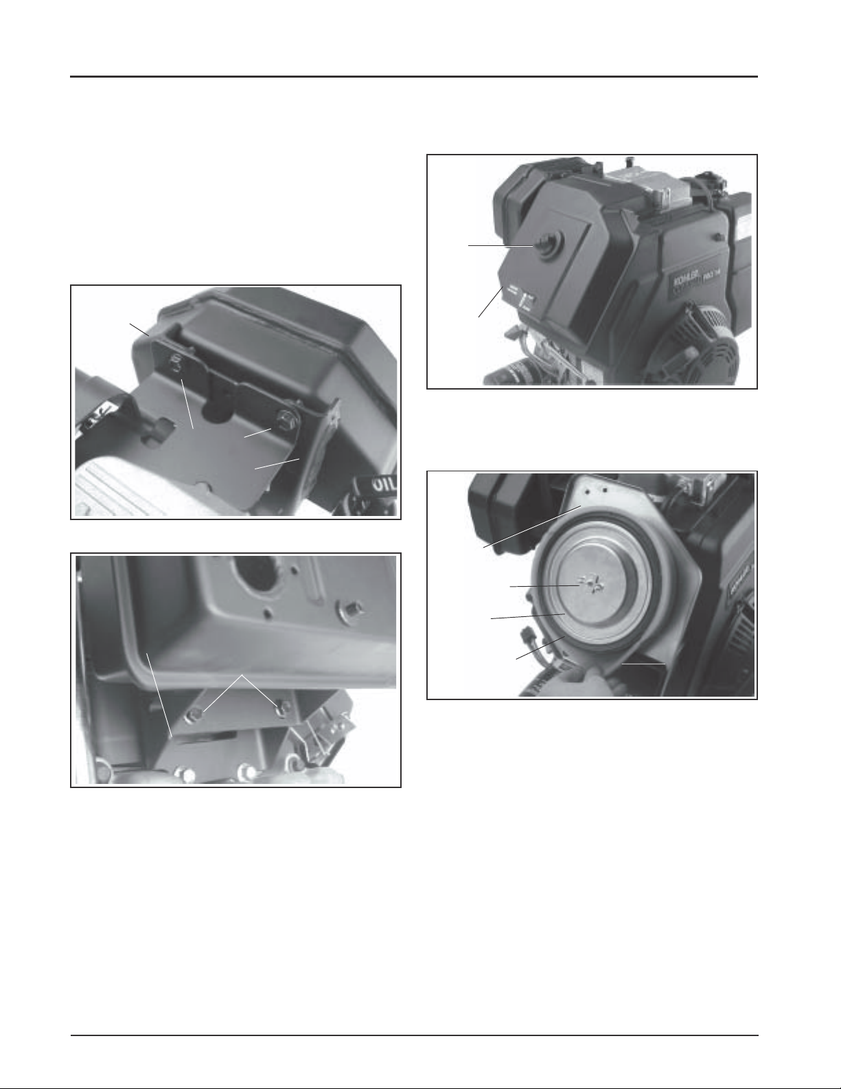
Section 9
Disassembly
Remove Muffler
1. Remove the four hex flange screws securing the
muffler to the upper and lower mounting
brackets. See Figures 9-2 and 9-3.
2. Remove the muffler from the mounting brackets
and exhaust inlet pipe.
3. Remove the two hex flange nuts from the exhaust
port studs and take off the exhaust inlet pipe and
gasket.
Muffler
Hex Flange
Screws
Upper
Muffler
Bracket
Remove Air Cleaner
1. Remove the knob and air cleaner cover. See
Figure 9-4.
Knob
Air Cleaner
Cover
Figure 9-4. Removing Air Cleaner Cover.
2. Remove the wing nut, washer, element cover,
element and precleaner. See Figure 9-5.
Figure 9-2. Removing Muffler.
Lower Mounting
Bracket
Figure 9-3. Removing Muffler.
Muffler
Hex Flange Screws
Air
Cleaner
Base
Wing Nut
Element
Cover
Paper
Element
Figure 9-5. Removing Air Cleaner Elements.
Foam
Precleaner
9.2
Page 77

3. Remove the hex flange nuts from the mounting
studs, and take off the air cleaner mounting
bracket, spitback cup or collector plate, and
gasket as equipped. See Figure 9-6.
Section 9
Disassembly
Air Cleaner
Base
Intake Studs
Figure 9-6. Removing Spitback Cup and Air
Cleaner Base.
4. Loosen the hose clamp and disconnect the
breather hose from the rocker arm cover. Remove
the air cleaner base from the studs and disconnect
the choke linkage from the carburetor choke
lever. See Figure 9-7.
Spitback
Cup
Mounting
Screws
Figure 9-8. Removing Throttle Control Bracket.
Throttle
Bracket Lever
Governor
Spring
Figure 9-9. Removing Spring From Throttle Lever.
Ground
Lead
Air
Cleaner
Base
Choke
Linkage
Figure 9-7. Removing Air Cleaner Base.
Remove Throttle Control Bracket
1. Remove the two mounting screws securing the
throttle control bracket and ground lead (some
models) to the crankcase. See Figure 9-8.
2. Mark the governor spring hole location and
unhook the spring from the lever of the throttle
control bracket. See Figure 9-8 and 9-9.
9
9.3
Page 78

Section 9
Disassembly
Remove Carburetor and Governor Lever
WARNING: Explosive Fuel!
Gasoline may be present in the carburetor and fuel system.
Gasoline is extremely flammable, and its vapors can explode
if ignited. Keep sparks, open flames, and other sources of
ignition away from the engine.
1. Remove the fuel line from the carburetor inlet
fitting. See Figure 9-10.
Fuel Line
Carburetor
Figure 9-10. Removing Fuel Line From Carburetor.
Remove Fuel Tank
WARNING: Explosive Fuel!
Gasoline may be present in the carburetor and fuel system.
Gasoline is extremely flammable, and its vapors can explode
if ignited. Keep sparks, open flames, and other sources of
ignition away from the engine.
1. Turn fuel shut-off valve to OFF (horizontal)
position. Disconnect fuel line from valve.
2. Remove hex flange nuts from lower bracket and
hex flange screws from upper bracket of fuel
tank. See Figure 9-12.
Upper Bracket
Mounting Screws
Shut-Off Valve
Lower Bracket
2. Loosen the fastener securing the governor lever
to the cross shaft.
3. Remove the carburetor and governor lever, with
the linkage attached, from the engine. See Figure
9-11.
Governor Lever
and Linkage
Carburetor
Figure 9-11. Removing Carburetor and Governor
Lever.
Hex Flange Nuts
Figure 9-12. Removing Fuel Tank.
3. Remove the fuel tank.
Fuel Tank
Remove Retractable Starter
1. Remove the five hex flange screws and retractable
starter. See Figure 9-13.
Retractable
Starter
Hex Flange Screw (5)
Figure 9-13. Removing Retractable Starter.
9.4
Page 79

Section 9
Disassembly
Remove Fuel Pump
WARNING: Explosive Fuel!
Gasoline may be present in the carburetor and fuel system.
Gasoline is extremely flammable, and its vapors can explode
if ignited. Keep sparks, open flames, and other sources of
ignition away from the engine.
1. Disconnect the fuel line from the outlet and inlet
fittings of the fuel pump. See Figure 9-14.
2. Remove the two hex flange screws, fuel pump,
and gasket.
Outlet
Hex Flange
Screws
Inlet
Fuel Pump
2. If starter is mounted on studs with a fuel tank/
solenoid bracket. See Figure 9-15.
a. Remove the two hex flange screws through
the closure plate. Note installation of spacer
washer behind bracket on lower screw. See
Figure 9-15.
b. Remove the screws securing the starter
(pinion) cover to the blower housing. See
Figure 9-16.
Cover
Figure 9-16. Removing Starter (pinion) Cover.
Hex Flange Screws
Figure 9-14. Removing Fuel Pump.
Remove Electric Starter
Electric Starter (Bendix Drive or Solenoid Shif t)
1. Disconnect the lead connected to the stud
terminal on the starter, or both leads from the
solenoid on solenoid shift starters.
Starter
Terminal/Lead
Spacer
Fuel T ank/Solenoid
Mounting Bracket
Figure 9-15. Removing Bendix Drive Starter.
Hex Flange
Mounting
Screws
c. Slide the starter and spacers off the studs.
Note position of ground lead (if used). See
Figure 9-17.
9
Spacers
Starter
Figure 9-17. Removing Starter and Spacers.
9.5
Page 80

Section 9
Disassembly
d. If removal of the mounting studs is required,
use the two hex flange nuts from the
mounting studs, tightened flange to flange, to
remove. See Figure 9-18.
Studs
Hex Flange Nuts
Mounting
Screws
Wire Connectors
Rectifier-Regulator
Figure 9-20. Removing Rectifier-Regulator.
Remove Oil Sentry
1. Disconnect the lead from the Oil SentryTM switch.
TM
Figure 9-18. Removing Mounting Studs.
If the starter is mounted with two hex flange screws,
remove the screws and pull the starter out from
behind the pinion cover.
Starter
Mounting Bolts
Figure 9-19. Starter Mounted With Bolts.
Remove Rectifier-Regulator
1. Remove the connector(s) from the rectifierregulator. See Figure 9-20.
2. Remove Oil SentryTM switch from the oil filter
adapter or adapter section of closure plate. See
Figure 9-21.
Oil Sentry
Switch
Figure 9-21. Removing Oil SentryTMSwitch.
TM
Lead
2. Remove the two hex flange screws securing the
rectifier-regulator and the attached ground lead
(non-metal blower housing only).
9.6
Page 81

Section 9
Disassembly
Remove Valve Cover
1. Remove the five hex flange valve cover screws.
Note the assembly orientation of any attached
brackets (lift, fuel tank, muffler) and loose spacers
if used. See Figure 9-22.
NOTE: The valve cover is sealed to the cylinder
head using RTV silicone sealant. When
removing valve cover, use care not to
damage the gasket surfaces of cover and
cylinder head. To break the RTV seal,
hold a block of wood against one of the
flat faces of the valve cover. Strike the
wood firmly with a mallet. If the seal
doesn't break loose after 1 or 2 attempts,
repeat the procedure on the other side.
Lift
Bracket
Muffler Bracket
Valve
Cover
Remove Blower Housing and Baffles
1. Remove the hex flange screws from the blower
housing and baffles. Disconnect the wire harness
from the key switch, if equipped. Remove the
blower housing, intake tube and baffles. See
Figures 9-24, 9-25, and 9-26.
Cylinder
Baffle
Figure 9-24. Removing Intake Side Cylinder Baffle.
Fuel Tank
Bracket
Figure 9-22. Removing Valve Cover.
Hex Flange
Screws
Remove Cylinder Head Baffle
1. Remove the hex flange screws securing the
cylinder head baffle to the cylinder head. See
Figure 9-23. Remove the baffle.
Cylinder
Head Baffle
Figure 9-23. Removing Cylinder Head Baffle.
Cylinder Baffle
(Starter Side)
9
Figure 9-25. Removing Starter Side Cylinder Baffle.
Indicator Light
Connectors
Blower
Housing
Figure 9-26. Disconnecting Indicator Light Leads
and Removing Blower Housing.
9.7
Page 82

Section 9
Disassembly
Remove Carburetor Adapter and Heat
Deflector
1. Remove the two socket head cap screw securing
carburetor adapter, gaskets and heat deflector to
the cylinder head. See Figure 9-27.
2. Remove the carburetor adapter, heat shield, and
gaskets from the engine. See Figure 9-27.
Figure 9-29. Removing Fuel Line.
Remove Cylinder Head
1. Remove the hex flange screws, spacer (from the
screw by the exhaust port), cylinder head, push
rods, and cylinder head gasket. See Figures 9-30
and 9-31. Mark the push rods for reassembly.
Discard the screws. Do not reuse.
Figure 9-27. Removing Carburetor Adapter and
Heat Deflector.
Remove Ignition Module
1. Disconnect the kill lead from the ignition module
terminal. See Figure 9-28.
2. Rotate flywheel magnet away from ignition
module.
3. Remove the two hex flange screws and ignition
module.
Kill
Lead
Ignition Module
Kill
Terminal
Breather Reed
Retainer and
Hex Flange
Screws
Figure 9-30. Removing Cylinder Head.
Cylinder
Head
Gasket
Breather Reed
Hex Flange
Screw and
Spacer
Figure 9-28. Removing Ignition Module.
Remove Fuel Line
1. Remove the hex flange screw, clip, and fuel line.
See Figure 9-29.
9.8
Figure 9-31. Removing Cylinder Head Gasket.
Page 83

Section 9
Disassembly
Disassemble Cylinder Head
Two basic types of heads are used. One type utilizes a
rocker bridge arrangement as shown in Figure 9-33.
The second type uses individually mounted rocker
arm assemblies, with or without a guide plate, rather
than a bridge. This type is shown in Figure 9-32.
Components are unique to each style of head. Follow
the appropriate procedure based upon the type of
head configuration involved.
NOTE: Before disassembly, mark all valve train
components to assure they are reassembled in
the same side if reused.
Valve Keepers
Rocker
Arm
Breather
Reed Parts
Figure 9-32. Head with Individually Mounted
Pivots/Rocker Arm.
Valve
Spring Cap
Rocker
Arm
Pivot
Ball
Guide
Plate
Exhaust Side
a. Remove the rocker shaft (from the breather
side of head), and rocker arms.
b. Remove the two hex cap screws and the
rocker bridge. See Figure 9-35.
Heads with Individually Mounted Pivots/
Rocker Arms - Figure 9-32.
c. Remove the hex flange screws securing the
rocker arm/pivot assemblies, and guide plate
(if so equipped), to the head.
4. Remove the valves.
a. Compress the valve springs using a valve
spring compressor. See Figure 9-32.
b. Remove the keepers, valve spring caps, valve
springs, the retainers* or exhaust valve rotator,
(early models only), and the intake valve stem
seal*.
*Not used on some models.
Valve Spring
Compressor
1. Remove the spark plug. See Figure 9-33.
Rocker Shaft Rocker Arms
Spark Plugs
Figure 9-33. Removing Spark Plug and Rocker
Arms.
2. Remove the hex flange screw, breather reed
retainer, and breather reed.
3. Rocker Bridge Equipped Heads - Figure 9-33.
Figure 9-34. Removing Valves With Valve Spring
Compressor.
Hex Cap
Screws
Keepers
Figure 9-35. Removing Valves.
Valve Spring Cap
Rocker
Bridge
Valve Spring
9
9.9
Page 84

Section 9
Disassembly
2. Unsnap and remove the grass screen from the
fan.
3. Remove the flywheel from the crankshaft using a
puller. See Figure 9-38.
Strap
Wrench
Flywheel
Figure 9-36. Removing Valves.
Remove Drive Cup, Grass Screen,
Flywheel, and Fan
NOTE: Always a the flywheel strap wrench or
holding tool to hold the flywheel when
loosening or tightening the flywheel and fan
retaining fasteners. Do not use any type of
bar or wedge between the fins of cooling fan
as the fins could become cracked or
damaged.
NOTE: Always use a puller to remove the flywheel
from the crankshaft. Do not strike the
crankshaft or flywheel, as these parts could
become cracked or damaged.
1. Remove the hex flange screw, plain washer, and
recoil starter drive cup*. See Figure 9-37.
*Not used on models with electric start only. On
these models the grass screen must be removed
first, to access the hex flange screw and washer.
Puller
Figure 9-38. Removing Flywheel With a Puller.
4. Remove the four hex flange screws and fan from
flywheel. See Figure 9-39.
Hex Flange
Screws (4)
Fan
Flywheel
Figure 9-39. Removing Fan From Flywheel.
Strap Wrench
Figure 9-37. Removing Flywheel Retaining Screw
and Drive Cup.
9.10
Remove the Stator and Wiring Harness
1. Remove the stator leads from the connector body.
2. Remove the hex flange screw and clip securing
the stator leads to the crankcase. See Figure
9-40.
3. Remove the hex flange screw and clip securing
the kill lead to the crankcase. Remove the four
hex socket head screws and stator.
Page 85

Section 9
Disassembly
NOTE: Insert the screwdriver only in the splitting
notches. Do not pry on the gasket surfaces of
the closure plate or crankcase as this can
cause leaks.
Remove Oil Pickup, Oil Pressure Relief
Valve, Oil Pump, and Oil Seal
1. Remove the oil seal from the closure plate. See
Figure 9-43.
2. Remove the hex flange screw, clip, oil pickup, and
O-Ring seal.
Figure 9-40. Removing Stator .
Remove Closure Plate
1. Remove the twelve hex flange screws securing the
closure plate to the crankcase. See Figure 9-41.
Figure 9-41. Removing Closure Plate.
2. Locate the splitting notches in the seam of the
closure plate and crankcase. See Figure 9-42. Pry
the closure plate from the crankcase using a large
flat-blade screwdriver.
3. Identify the type of oil pressure relief valve used.
If the relief valve assembly is like that shown in
Figure 9-44, remove the hex socket screw,
retaining bracket, valve body, piston, and spring.
If the relief valve is like that shown in Figure 9-45
removal is not necessary. See the note on the next
page.
Oil Pickup
Figure 9-43. Removing Oil Seal and Pickup.
Relief Valve
Bracket
Hex Socket
Screw
9
Splitting
Notch
Figure 9-42. Splitting Notch of Closure Plate/
Crankcase.
Spring
Piston
Valve Body
Figure 9-44. Removing Oil Pressure Relief Valve
Body , Piston, and Spring (Early S tyle).
9.11
Page 86

Section 9
Disassembly
Figure 9-45. Later Style Oil Pressure Relief Valve.
*NOTE: Later style one-piece relief valves (Figure
9-45) are staked in place and do not require
removal unless replacement is intended.
4. Remove the three hex flange screws, oil pump
cover, O-Ring, and oil pump rotors. See Figure
9-46.
Remove Camshaft and Hydraulic Lifters
1. Remove the camshaft and shim. See Figure 9-47.
Shim
Camshaft
Figure 9-47. Removing Camshaft.
2. Mark or identify the hydraulic lifters as either
intake or exhaust. See Figure 9-48. Remove the
lifters from the crankcase.
NOTE: The intake hydraulic lifter is farthest from
the crankcase gasket surface. The exhaust
hydraulic lifter is nearest to the crankcase
gasket surface.
O-Ring
Oil Pump
Rotors
Hex Flange Screws
Figure 9-46. Removing Oil Pump.
Exhaust Valve
Lifter
Oil Pump
Cover
Intake V alve
Lifter
Figure 9-48. Identifying Hydraulic Lifters.
NOTE: Do not use a magnet to remove hydraulic
lifters.
NOTE: Some applications do not require
cylinder head removal for lifter
replacement.
9.12
Page 87

Section 9
Disassembly
Remove Balance Shaft
1. Remove the balance shaft from the crankcase. See
Figure 9-49.
Balance
Shaft
Figure 9-49. Removing Balance Shaft.
Remove Connecting Rod and Piston
1. Remove the two hex flange screws and
connecting rod cap. See Figure 9-50.
NOTE: If a carbon ridge is present at the top of
the bore, use a ridge reamer tool to
remove it before attempting to remove
the piston.
Remove Piston From Connecting Rod
1. Remove the wrist pin retainer and wrist pin.
Separate the piston from the connecting rod. See
Figure 9-51.
Piston
Wrist Pin
Retainer
Connecting
Rod
Figure 9-51. Removing Piston From Connecting
Rod.
Wrist
Pin
Remove Piston Rings
1. Remove the top and center compression rings
using a ring expander tool. See Figure 9-52.
Piston Ring
2. Carefully push the connecting rod and the piston
away from the crankshaft and out of the cylinder
bore.
Connecting
Rod Cap
Hex Flange
Screws
Figure 9-50. Removing Connecting Rod.
9
Piston Ring
Expander
Figure 9-52. Removing Piston Rings.
2. Remove the oil control ring rails, then remove the
rails spacer.
9.13
Page 88

Section 9
Disassembly
Remove Crankshaft
1. Remove the woodruff key from the flywheel end
of crankshaft.
2. Remove the crankshaft from the crankcase. See
Figure 9-53.
Crankshaft
Cross Shaft Oil Seal
Figure 9-55. Removing Cross Shaft Oil Seal.
4. If necessary, remove the governor gear and
regulating pin. See Figure 9-56.
Regulating Pin
Figure 9-53. Removing Crankshaft.
Remove Flywheel End Oil Seal
1. Remove the oil seal from crankcase.
Remove Governor Cross Shaft and
Governor Gear
1. Remove the hitch pin and plain washer from the
governor cross shaft. See Figure 9-54.
2. Remove the cross shaft and plain washer from the
crankcase.
Plain Washer
Hitch Pin
Plain
Washer
Governor
Cross Shaft
Governor Gear
Figure 9-56. Removing Governor Gear.
NOTE: The governor gear is held onto the governor
gear shaft by small molded tabs in the gear.
When the gear is removed from the shaft
these tabs are destroyed. This will require
replacement of the gear, therefore, remove
the gear only if absolutely necessary (such as
when reboring, doing major engine
rebuilding, etc.).
Figure 9-54. Removing Governor Cross Shaft.
3. Remove the governor cross shaft oil seal from the
crankcase. See Figure 9-55.
9.14
Page 89

Internal Components
Section 10
Inspection and Reconditioning
Section 10
This section covers the operation, inspection, and
repair/reconditioning of major internal engine
components. The following components are not
covered in this section. They are covered in sections of
their own:
Air Cleaner, Section 4
Carburetor & External Governor, Section 5
Ignition, Charging & Electric Starter, Section 8
Clean all parts thoroughly. Only clean parts can be
accurately inspected and gauged for wear or damage.
There are many commercially available cleaners that
will quickly remove grease, oil, and grime from
engine parts. When such a cleaner is used, follow the
manufacturer’s instructions and safety precautions
carefully. Make sure all traces of the cleaner are
removed before the engine is reassembled and placed
into operation. Even small amounts of these cleaners
can quickly break down the lubricating properties of
engine oil.
Use an aerosol gasket remover, paint stripper, or
lacquer thinner to remove any old sealant. Apply the
solvent, allow time for it to work, and then brush the
surface with a brass wire brush. After the old sealant
is removed, clean the surface with isopropyl alcohol,
lacquer thinner, or aerosol electrical contact cleaner.
Do not scrape the surfaces, as any scratches, nicks, or
burrs can result in leaks. See Service Bulletin 252 for
further information.
Refer to A Guide to Engine Rebuilding (TP-2150-A)
for additional information. Measurement Guide
(TP-2159-B) and Engine Inspection Data Record
(TP-2435) are also available; use these to record
inspection results.
Automatic Compression Release (ACR)
This engine is equipped with an Automatic
Compression Release (ACR) mechanism. ACR lowers
compression at cranking speeds to make starting
easier.
Operation
The ACR mechanism consists of a lever and control
pin assembly attached to the gear on the camshaft. At
cranking speeds (700 RPM or lower), the control pin
protrudes above the exhaust cam lobe. This pushes the
exhaust valve off its seat during the first part of the
compression stroke. The reduced compression results
in an effective compression ratio during cranking of
about 2:1.
After starting, engine speed increases to over 700
RPM. Centrifugal force moves the lever and the
control pin drops into the recess in the exhaust cam
lobe. When in the recess, the control pin has no effect
on the exhaust valve and the engine operates at full
power.
When the engine is stopped, the spring returns the
lever and control pin assembly to the compression
release position ready for the next start.
Camshaft
Inspection and Service
Inspect the gear teeth of the camshaft. If the teeth are
badly worn, chipped, or some are missing,
replacement of the camshaft and crankshaft will be
necessary.
Crankshaft
Inspection and Service
Inspect the gear teeth of the crankshaft. If the teeth are
badly worn, chipped, or some are missing,
replacement of the crankshaft will be necessary.
Inspect the crankshaft bearings for scoring, grooving,
etc. Do not replace bearings unless they shown signs
of damage or are out of running clearance
specifications. If the crankshaft turns easily and
noiselessly, and there is no evidence of scoring,
grooving, etc., on the races or bearing surfaces, the
bearings can be reused.
10
10.1
Page 90

Section 10
Internal Components
Inspect the crankshaft keyways. If worn or chipped,
replacement of the crankshaft will be necessary.
Inspect the crankpin for score marks or metallic
pickup. Slight score marks can be cleaned with crocus
cloth soaked in oil. If wear limits, as stated in
“Specifications and Tolerances” are exceeded, it will
be necessary to either replace the crankshaft or regrind
the crankpin to 0.25 mm (0.010 in.) undersize. If
reground, a 0.25 mm (0.010 in.) undersize connecting
rod (big end) must then be used to achieve proper
running clearance. Measure the crankpin for size,
taper, and out-of-round.
Crankcase
Inspection and Service
Check all gasket surfaces to make sure they are free of
gasket fragments. Gasket surfaces must also be free of
deep scratches or nicks.
Check the cylinder bore wall for scoring. In severe
cases, unburned fuel can cause scuffing and scoring of
the cylinder wall, washing the necessary lubricating
oils off the piston and cylinder wall. As raw fuel seeps
down the cylinder wall, the piston rings make metal to
metal contact with the wall. Scoring of the cylinder
wall can also be caused by localized hot spots
resulting from blocking cooling fins or from
inadequate or contaminated lubrication.
2. With the lower edge of each stone positioned
even with the lowest edge of the bore, start drill
and honing process. Move the hone up and down
while resizing to prevent the formation of cutting
ridges. Check the size frequently.
NOTE: Measure the piston diameter and resize
the bore to the piston to obtain the
specified running clearances. Keep in
mind the temperatures caused by honing
may cause inaccurate measurements.
Make sure the bore is cool when
measuring.
3. When the bore is within 0.064 mm (0.0025 in.) of
desired size, remove the coarse stones and
replace with burnishing stones. Continue with
the burnishing stones until within 0.013 mm
(0.0005 in.) of desired size and then use finish
stones (220-280 grit) and polish to final size. A
crosshatch should be observed if honing is done
correctly. The crosshatch should intersect at
approximately 23-33° off the horizontal. Too flat
of an angle could cause the rings to skip and wear
excessively, too steep of an angle will result in
high oil consumption (refer to Figure 10-1).
If the cylinder bore is badly scored, excessively worn,
tapered, or out of round, resizing is necessary. Use an
inside micrometer to determine amount of wear (refer
to the “Specifications, Tolerances, and Special Torque
Values”, in Section 1), then select the nearest suitable
oversize of either 0.25 mm (0.010 in.) or 0.50 mm
(0.020 in.). Resizing to one of these oversizes will
allow usage of the available oversize piston and ring
assemblies. Initially, resize using a boring bar, then use
the following procedures for honing the cylinder.
Honing
While most commercially available cylinder hones can
be used with either portable drills or drill presses, the
use of a low speed drill press is preferred as it
facilitates more accurate alignment of the bore in
relation to the crankshaft crossbore. Honing is best
accomplished at a drill speed of about 250 RPM and
60 strokes per minute. After installing coarse stones in
hone, proceed as follows:
1. Lower hone into bore and after centering, adjust
so that the stones are in contact with the cylinder
wall. Use of a commercial cutting-cooling agent is
recommended.
Figure 10-1. Cylinder Bore Crosshatch after
Honing.
4. After resizing, check the bore for roundness,
taper, and size. Use an inside micrometer,
telescoping gauge, or bore gauge to take
measurements. The measurements should be
taken at three locations in the cylinder - at the top,
middle, and bottom. Two measurements should
be taken perpendicular to each other) at each of
the three locations.
10.2
Page 91

Section 10
Internal Components
Clean Cylinder Bore after Honing
Proper cleaning of the cylinder walls following boring
and/or honing is very critical to a successful overhaul.
Machining grit left in the cylinder bore can destroy an
engine in less than one hour of operation after a
rebuild.
The final cleaning operation should always be a
thorough scrubbing with a brush and hot, soapy
water. Use a strong detergent that is capable of
breaking down the machining oil while maintaining a
good level of suds. If the suds break down during
cleaning, discard the dirty water and start again with
more hot water and detergent. Following the
scrubbing, rinse the cylinder with very hot, clear
water, dry it completely, and apply a light coating of
engine oil to prevent rusting.
Measuring Piston-to-Bore Clearance
Before installing the piston into the cylinder bore, it is
necessary that the clearance be accurately checked.
This step is often overlooked, and if the clearances are
not within specifications, engine failure will usually
result.
NOTE: Do not use a feeler gauge to measure piston-
to-bore clearance - it will yield inaccurate
measurements. Always use a micrometer.
Use the following procedure to accurately measure
the piston-to-bore clearance:
2. Use an inside micrometer, telescoping gauge, or
bore gauge and measure the cylinder bore. Take
the measurement approximately 63.5 mm
(2.5 in.) below the top of the bore and
perpendicular to the piston pin.
3. Piston-to-bore clearance is the difference between
the bore diameter and the piston diameter (step 2
minus step 1).
Flywheel
Inspection
Inspect the flywheel for cracks, and the flywheel
keyway for damage. Replace flywheel if cracked.
Replace the flywheel, the crankshaft, and the key if
flywheel key is sheared or the keyway damaged.
Inspect the ring gear for cracks or damage. Kohler
does not provide ring gears as a serviceable part.
Replace the flywheel if the ring gear is damaged.
Cylinder Head and Valves
Inspection and Service
Carefully inspect the valve mechanism parts. Inspect
the valve springs and related hardware for excessive
wear or distortion. Check the valves and valve seat
area or inserts for evidence of deep pitting, cracks, or
distortion. Check clearance of the valve stems in
guides. See Figure 10-3 for valve details and
specifications.
1. With a micrometer, measure the diameter of the
piston perpendicular to the piston pin, and up
from the bottom of the piston skirt as indicated in
Figure 10-2, based on the model involved.
6 mm (0.24 in.) on CH11-14 engines
8 mm (0.31 in.) on CH15, 16 engines
Above the Bottom of Piston Skirt
at Right Angels to Piston Pin.
Figure 10-2. Measuring Piston Diameter.
10
10.3
Page 92

Section 10
Internal Components
Exhaust Valve
E
G
H
Dimension
A
B
C
D
E
F
G
H
Figure 10-3. Valve Det ails.
Seat Angle
Insert O.D.
Guide Depth
Guide I.D.
Valve Head Diameter
Valve Face Angle
Valve Margin (Min.)
Valve Stem Diameter
Intake V alve
F
C
D
D
89°
37.987/38.013 mm
6.5 mm
7.033/7.058 mm
35.63/35.37 mm
45°
1.5 mm
6.982/7.000 mm
B
A
B
Intake
Exhaust
Insert
Intake
Insert
F
A
A
E
G
H
Exhaust
89°
34.013/33.987 mm
6.5 mm
7.033/7.058 mm
31.63/31.37 mm
45°
1.5 mm
6.970/6.988 mm
Hard starting, or loss of power accompanied by high
fuel consumption may be symptoms of faulty valves.
Although these symptoms could also be attributed to
worn rings, remove and check the valves first. After
removal, clean the valve heads, faces, and stems with a
power wire brush.
Then, carefully inspect each valve for defects such as
warped head, excessive corrosion, or worn stem end.
Replace valves found to be in bad condition.
Valve Guides
If a valve guide is worn beyond specifications, it will
not guide the valve in a straight line. This may result
in burnt valve faces or seats, loss of compression, and
excessive oil consumption.
To check valve guide to valve stem clearance,
thoroughly clean the valve guide and, using a splitball gauge, measure the inside diameter. Then, using
an outside micrometer, measure the diameter of the
valve stem at several points on the stem where it
moves in the valve guide. Use the largest stem
diameter to calculate the clearance. If the clearance
exceeds 7.134 mm (0.2809 in.) on intake or 7.159 mm
(0.2819 in.) on exhaust valve, determine whether the
valve stem or the guide is responsible for the excessive
clearance.
If the valve stem diameter is within specifications,
then recondition the valve guide.
Reconditioning V alve Guide
The valve guides in the cylinder head are not
removable. Use a 0.25 mm (0.010 in.) O/S reamer (See
Section 2).
10.4
Page 93

Section 10
Internal Components
Valve Seat Inserts
Intake valve seats are usually machined into the
cylinder head, however, certain applications may
specify hard alloy inserts. The valve seats are not
replaceable. If cracked or badly warped, the cylinder
head should be replaced.
Use a standard valve seat cutter (see Figure 10-4) and
cut seat to dimensions shown in Figure 10-3 (valve
details illustration).
V alve Seat Cutter
Pilot
Normally, very little wear takes place in the piston
boss-piston pin area. If the original piston and
connecting rod can be reused after new rings are
installed, the original pin can also be reused but new
piston pin retainers are required. The piston pin is
included as part of the piston assembly - if the pin
boss or the pin are worn or damaged, a new piston
assembly is required.
Ring failure is usually indicated by excessive oil
consumption and blue exhaust smoke. When rings
fail, oil is allowed to enter the combustion chamber
where it is burned along with the fuel. High oil
consumption can also occur when the piston ring end
gap is incorrect. Oil control is also lost when ring gaps
are not staggered during installation.
When cylinder temperatures get too high, lacquer and
varnish collect on pistons causing rings to stick which
results in rapid wear. A worn ring usually takes on a
shiny or bright appearance.
Scratches on rings and pistons are caused by abrasive
material such as carbon, dirt, or pieces of hard metal.
Figure 10-4. Standard Valve Seat Cutter.
Lapping V alves
Reground or new valves must be lapped in, to provide
fit. Lightly coat valve face with fine grade of grinding
compound. Use a hand valve grinder with suction
cup for final lapping. Clean and dry cylinder head
and apply a light coating of SAE 10 oil to prevent
rusting.
Intake Valve Stem Seal
These engines use valve stem seals on the intake
valves. Always use a new seal when valves are
removed from cylinder head. The seals should also be
replaced if deteriorated or damaged. Never reuse an
old seal.
Pistons and Rings
Inspection
Scuffing and scoring of pistons and cylinder walls
occurs when internal temperatures approach the
welding point of the piston, usually attributed to
improper lubrication, and/or overheating of the
engine.
Detonation damage occurs when a portion of the fuel
charge ignites spontaneously from heat and pressure
shortly after ignition. This creates two flame fronts
which meet and explode to create extreme hammering
pressures on a specific area of the piston. Detonation
generally occurs from using fuels with low octane.
Preignition or ignition of the fuel charge before the
timed spark can cause damage similar to detonation.
Preignition damage is often more severe than
detonation damage - often a hole is quickly burned
right through the piston dome. Preignition is caused
by a hot spot in the combustion chamber from sources
such as: glowing carbon deposits, blocked fins,
improperly seated valve, or wrong spark plug.
See Figure 10-5 for some common types of piston and
ring damage.
10
10.5
Page 94

Section 10
Internal Components
Stuck, Broken Rings Abrasive Scratched Rings
Overheated or Deteriorated Oil
Figure 10-5. Common T ypes of Piston and Ring Damage.
Replacement pistons are available in STD bore size,
and in 0.25 mm (0.010 in.), and 0.50 mm (0.20 in.)
oversizes. Replacement pistons include new piston
ring sets and new piston pins.
Service replacement piston rings sets are also available
separately for STD, 0.25 mm (0.010 in.), and 0.50 mm
(0.020 in.), oversized pistons. Always use new piston
rings when installing pistons. Never reuse old rings.
The cylinder bore must be deglazed before service
ring sets are used.
Some important points to remember when servicing
piston rings:
1. If the cylinder bore does not need reboring and if
the old piston is within wear limits and free of
score or scuff marks, the old piston may be
reused.
Scored Piston and Rings
2. Remove old rings and clean up grooves. Never
reuse old rings.
3. Before installing the rings on the piston, place the
top two rings, each in turn, in its running area in
the cylinder bore and check end gap using a
feeler gauge (see Figure 10-6). Compare findings
against specs below:
T op and Center Compression Ring End Gap
CH11, 12.5, 13, and 14
New Bore .............. 0.3/.05 mm (0.012/0.020 in)
Used Bore (Max.) . 0.77 mm (0.030 in)
CH15, 16
Top Compression Ring End Gap
New Bore.............. 0.2800/0.5100 mm (0.011/0.020 in)
Used Bore (Max.) . 0.79 mm (0.031 in)
Center Compression Ring End Gap
New Bore.............. 0.2200/0.4800 mm (0.0086/0.018 in)
Used Bore (Max.) . 0.76 mm (0.029 in)
10.6
Page 95

Piston Ring
Section 10
Internal Components
Figure 10-6. Measuring Piston Ring End Gap.
4. After installing the new compression (top and
middle) rings on the piston, check the "piston-toring" side clearance. See Figure 10-7 Compare
findings against the maximum recommended
side clearances listed below. If side clearance are
greater than specified, a new piston must be used.
Compression Ring-T o-Grove Side Clearance
CH11, 12.5, 13, and 14
Top ................. 0.040/0.150 mm (0.0016/0.0041 in.)
Middle .......... 0.040/0.072 mm (0.0016/0.0028 in.)
CH15, 16
Top ................. 0.0600/0.1050 mm (0.00236/0.00413 in)
Middle .......... 0.0400/0.0850 mm (0.00157/0.00335 in.)
End Gap
‘‘Pip’’ Mark
Piston
T op Compression Ring
Center Compression
Oil Control Ring
Expander
Figure 10-8. Piston Ring Installation.
1. Oil Control Ring (Bottom Groove): Install the
expander and then the rails. Make sure the ends
of expander are not overlapped.
Dykem
Rails
Figure 10-7. Measuring Piston Ring Side
Clearance.
Install Piston Rings
To install piston rings, proceed as follows:
NOTE: Rings must be installed correctly. Ring
installation instructions are usually included
with new rings sets. Follow instructions
carefully. Use a piston ring expander to install
rings. Install the bottom (oil control) ring first
and the top compression ring last. Refer to
Figure 10-8.
2. Compression Ring (Center Groove): Install the
center ring using a piston ring installation tool.
Make sure the “pip” mark is up and the PINK
dykem stripe is to the left of end gap.
3. Compression Ring (Top Groove): Install the top
ring using a piston ring installation tool. Make
sure the “pip” mark is up and the BLUE dykem
stripe is to the left of end gap.
Connecting Rods
Offset Stepped-Cap Connecting Rods are used in all
these engines.
Inspection and Service
Check bearing area (big end) for excessive wear, score
marks, running and side clearances (refer to Section 1,
Specifications, Tolerances, and Special Torque Values).
Replace rod and cap if scored or excessively worn.
Service replacement connecting rods are available in
STD crankpin size and 0.25 mm (0.010 in.) undersize.
Always refer to the appropriate parts information to
ensure that correct replacements are used.
10
10.7
Page 96

Section 10
Internal Components
Oil Pump
Inspection and Service
Pump can be checked/replaced without removing
closure plate.
Oil Pressure Relief Valve
If an original style (five-piece) oil pressure relief valve
is used (see Figure 10-9), check that piston and body
are free of nicks or burrs. Check the spring for any
wear or distortion. The free length of the spring
should be approximately 0.992 in. Replace the spring
if worn, out of specification, or damaged/distorted.
If the later style (one-piece) oil pressure relief valve
(see Figure 10-10) is used (staked to the closure plate),
check to see that the internal spring-loaded piston is
free. Remove the valve only if it needs to be replaced.
Relief Valve
Bracket
Spring
Hex Socket
Screw
Hydraulic Lifters
Inspection
Check the base surface of the hydraulic lifters for
wear or damage. If the lifters need to be replaced,
apply a liberal coating of Kohler lubricant (see Section
2) to the base of each new lifter before it is installed.
Bleeding the Lifters
To prevent a possible bent push rod or broken rocker
arm, it is important to bleed any excess oil out of the
lifters before they are installed.
1. Cut a 50-75 mm (2-3 in.) piece from the end of an
old push rod and chuck it in a drill press.
2. Lay a rag or shop towel on the table of the drill
press and place the lifter, open end up, on the
towel.
3. Lower the chucked push rod until it contacts the
plunger in the lifter. Slowly pump the plunger
two or three times to force the oil out of the feed
hole in the side of the lifter.
Piston
Valve Body
Figure 10-9. Five-Piece Oil Pressure Relief Valve.
Figure 10-10. One-Piece Oil Pressure Relief Valve.
Governor Gear
Inspection
Inspect the governor gear teeth. Look for any evidence
of worn, chipped, or cracked teeth. If one or more of
these problems is noted, replace the governor gear.
Stamped Steel Valve Cover
If the engine has stamped steel valve cover, the sealing
surface must be checked for flatness prior to
reinstallation. Hold the valve cover down firmly
against a flat, level surface or piece of glass, and check
around the entire perimeter that a 0.012 in. (0.30 mm)
feeler gauge cannot be inserted anywhere. See Figure
10-11. If the gauge goes in anywhere, the cover needs
to be replaced.
Figure 10-11. Checking with Feeler Gauge.
The governor gear must be replaced once it is
removed from the engine.
10.8
Page 97

Section 11
Reassembly
Section 11
Reassembly
The following sequence is suggested for complete
engine reassembly. This procedure assumes that all
components are new or have been reconditioned, and
all component subassembly work has been completed.
This procedure may be varied to accommodate
options or special equipment.
NOTE: Make sure the engine is assembled using all
specified torque values, tightening sequences,
and clearances. Failure to observe
specifications could cause severe engine wear
or damage.
NOTE: Always use new gaskets.
Typical Reassembly Sequence
1. Install governor gear and cross shaft.
2. Install crankshaft.
3. Install piston rings.
4. Assemble piston to connecting rod.
5. Install piston and connecting rod.
6. Install balance shaft.
7. Install hydraulic lifters and camshaft.
8. Check camshaft end play.
9. Install closure plate.
10. Install oil pump.
11. Install oil seal (PTO and Flywheel End).
12. Install stator and wiring harness.
13. Install flywheel, fan, grass screen and drive cup.
14. Install fuel line.
15. Install ignition module.
16. Assemble and install cylinder head.
17. Install carburetor adapter and heat deflector.
18. Install baffles and blower housing.
19. Install valve cover and muffler bracket.
20. Install fuel pump.
21. Install electric starter.
22. Install fuel tank.
23. Install rectifier-regulator.
24. Install carburetor and external governor
components.
25. Install throttle bracket.
26. Install air cleaner base, air intake system, adjust
governor lever.
27. Install retractable starter.
28. Install muffler.
29. Prepare engine for operation.
30. Test engine.
Install Governor Gear and Cross Shaft
NOTE: Reuse of an old (removed) governor gear is
not recommended.
1. Install the thrust washer to governor gear shaft.
2. Position the regulating pin to governor gear/
flyweights as shown in Figure 11-1. Slide the
governor gear/regulating pin over the governor
gear shaft.
Regulating
Pin
Governor
Gear
Thrust
Washer
11
Figure 11-1. Inst alling Governor Gear.
11.1
Page 98

Section 11
Reassembly
3. Using the an oil seal installer, install a new
governor cross shaft oil seal into the crankcase.
See Figure 11-2.
Seal
Installer
Cross Shaft
Oil Seal
Figure 11-2. Cross Shaf t Oil Seal.
4. Install one plain washer to the cross shaft and
insert the cross shaft (from inside crankcase)
through the crankcase and oil seal. See Figure
11-3.
5. Install one plain washer and hitch pin.
Crankshaft
Figure 11-4. Inst alling Crankshaft.
Install Piston Rings
NOTE: For detailed piston inspection procedures
and piston ring installation procedure, refer
to Section 10.
Assemble Piston to Connecting Rod
1. Assemble the piston, connecting rod, piston pin,
and piston pin retainers. See Figure 11-5.
Piston
Plain
Washer
Hitch
Pin
Governor
Cross
Shaft
Plain Washer
Figure 11-3. Inst alling Cross Shaft.
Install Crankshaft
1. Lubricate the flywheel end bearing surfaces of the
crankshaft and crankcase with engine oil.
2. Insert the crankshaft through the flywheel end
bearing. See Figure 11-4.
Wrist Pin
Retainer
Connecting
Rod
Wrist Pin
Figure 11-5. Inst alling Piston To Connecting Rod.
Install Piston and Connecting Rod
NOTE: Proper orientation of the piston/connecting
rod inside the engine is extremely important.
Improper orientation can cause extensive
wear or damage.
1. Stagger the piston rings in the grooves until the
end gaps are 120° apart.
11.2
Page 99

2. Lubricate the cylinder bore, piston, and rings
with engine oil. Compress the piston rings using
a piston ring compressor. See Figure 11-6. Push
the piston through the compressor so the oil
control (bottom) ring is just above the lower edge
of the compressor.
Section 11
Reassembly
Arrow Must
Point T owards
Flywheel
Figure 11-7. Piston Installation Identifier.
Piston Ring
Compressor Installed
Around Piston
Figure 11-6. Inst alling Piston and Connecting Rod.
3. Place the ring compressor on the top surface of
the crankcase and make certain it is seated down
around the entire circumference. The FLY arrow
on the piston should point toward the flywheel
side of the crankcase. See Figure 11-7. Use a soft,
rubber grip hammer handle and tap the piston/
connecting rod into the bore. The first tap should
be rather firm, so the oil ring moves from the
compressor into the bore in one smooth, quick
motion. Otherwise the oil ring rails may spring
out and jam between the ring compressor and
the top of the bore.
4. Lubricate the crankshaft journal and connecting
rod bearing surfaces with engine oil. Install the
rod cap to the connecting rod.
5. Three different types of connecting rod bolts have
been used in production, and each has a different
specific torque value. See Figures 11-8 and 11-9.
The 8 mm straight shank style rod bolts must be
torqued in increments to 22.7 N·m (200 in. lb.).
The 8 mm step-down shank style rod bolts must
be torqued in increments to 14.7 N·m
(130 in. lb.). The 6 mm straight shank style rod
bolts must be torqued in increments to 11.3 N·m
(100. in. lb.). Illustrated instructions are also
provide in the service rod package.
Torque these to 22.7 N·m (200 in. lb.)
8 mm Straight Shank
T orque these to 14.7 N·m (130 in. lb.)
8 mm Step-Down Shank
T orque these to 11.3 N·m (100 in. lb.)
6 mm Straight Shank
11
Figure 11-8. Connecting Rod Bolt s.
11.3
Page 100

Section 11
Reassembly
Connecting
Rod Cap
Connecting
Rod Bolts
Figure 11-9. Inst alling Connecting Rod Fasteners.
6. Rotate the crankshaft until the piston is at top
dead center (TDC) in the cylinder bore.
Install Balance Shaft
1. Lubricate the balance shaft bearing surfaces of the
crankcase and balance shaft with engine oil.
2. Align the timing mark on the balance shaft gear
and the larger gear on the crankshaft. Lower the
balance shaft into the bearing surface in the
crankcase.
3. Make sure the balance shaft gear, large crankshaft
gear and the governor gear teeth mesh and the
timing marks are aligned. See Figure 11-10.
Install Hydraulic Lifters and Camshaft
1. See Hydraulic Lifters in Section 10 for lifter
preparation (bleed down) procedures.
2. Apply camshaft lubricant (Kohler Part No.
25 357 14-S) to the bottom surface of each lifter.
See Figure 11-11a. Lubricate the hydraulic lifters
and the lifter bores in the crankcase with engine
oil.
Figure 11-1 1a. Applying Camshaf t Lubricant to
Bottom of Lifters.
3. Note the mark or tag identifying the hydraulic
lifters as either intake or exhaust. Install the
hydraulic lifters into the crankcase. See Figure
11-11b.
Crankshaft Timing
Mark (Large Crankgear)
Balance Shaft
Timing Mark
Figure 11-10. Aligning Timing Marks on Crank Gear
and Balance Shaft Gear.
NOTE: Install lifters in the same position as
before disassembly. The exhaust lifters
are located on the output shaft (oil pan)
side of the engine while the intake lifters
are located on the fan side of the engine.
Figure 11-1 1b. Inst alling Hydraulic Lifters.
11.4
 Loading...