

Page 1
COMMAND CH11-16
HORIZONTAL CRANKSHAFT
OWNER'S MANUAL
1
Page 2
Safety Precautions
To ensure safe operations please read the following statements and understand their meaning.
Also refer to your equipment owner's manual for other important safety information. This manual
contains safety precautions which are explained below. Please read carefully.
WARNING
Warning is used to indicate the presence of a hazard that can cause severe personal injury,
death, or substantial property damage if the warning is ignored.
CAUTION
Caution is used to indicate the presence of a hazard that will or can cause minor personal injury
or property damage if the caution is ignored.
NOTE
Note is used to notify people of installation, operation, or maintenance information that is
important but not hazard-related.
For Y our Safety!
These precautions should be followed at all times. Failure to follow these precautions could result
in injury to yourself and others.
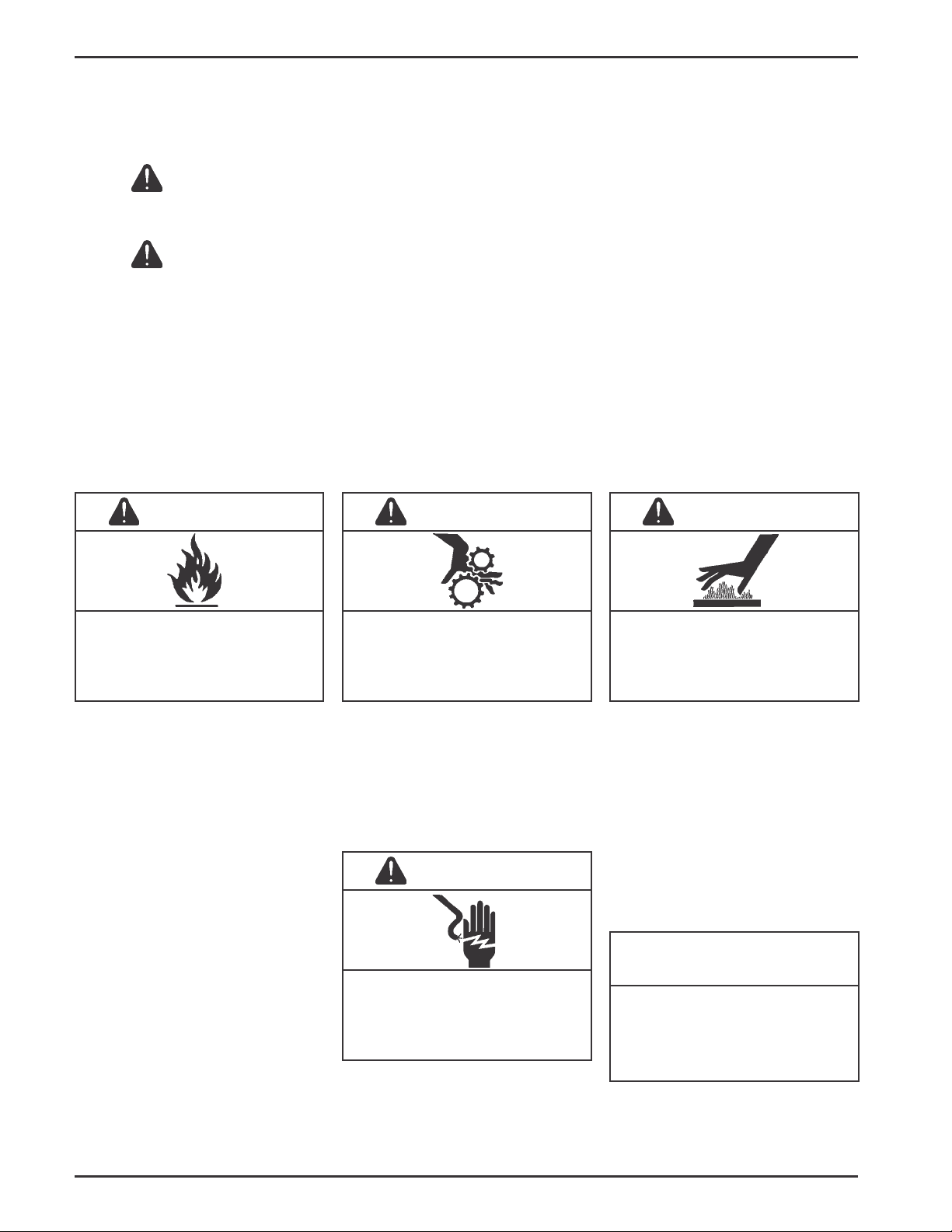
WARNING
Explosive Fuel can cause fires and
severe burns.
Do not fill the fuel tank while the
engine is hot or running.
Explosive Fuel!
Gasoline is extremely flammable
and its vapors can explode if
ignited. Store gasoline only in
approved containers, in well
ventilated, unoccupied buildings,
away from sparks or flames. Do not
fill the fuel tank while the engine is
hot or running, since spilled fuel
could ignite if it comes in contact
with hot parts or sparks from
ignition. Do not start the engine near
spilled fuel. Never use gasoline as a
cleaning agent.
WARNING
Rotating Parts can cause severe
injury.
Stay away while engine is in
operation.
Rotating Parts!
Keep hands, feet, hair, and clothing
away from all moving parts to
prevent injury. Never operate the
engine with covers, shrouds, or
guards removed.
CAUTION
Electrical Shock can cause injury.
Do not touch wires while engine is
running.
Electrical Shock!
Never touch electrical wires or
components while the engine is
running. They can be sources of
electrical shock.
WARNING
Hot Parts can cause severe burns.
Do not touch engine while operating
or just after stopping.
Hot Parts!
Engine components can get
extremely hot from operation. To
prevent severe burns, do not touch
these areas while the engine is
running, or immediately after it is
turned off. Never operate the engine
with heat shields or guards
removed.
California
Proposition 65 Warning
Engine exhaust from this product
contains chemicals known to the
State of California to cause cancer,
birth defects, or other reproductive
harm.
2
Page 3
Safety Precautions (Cont.)
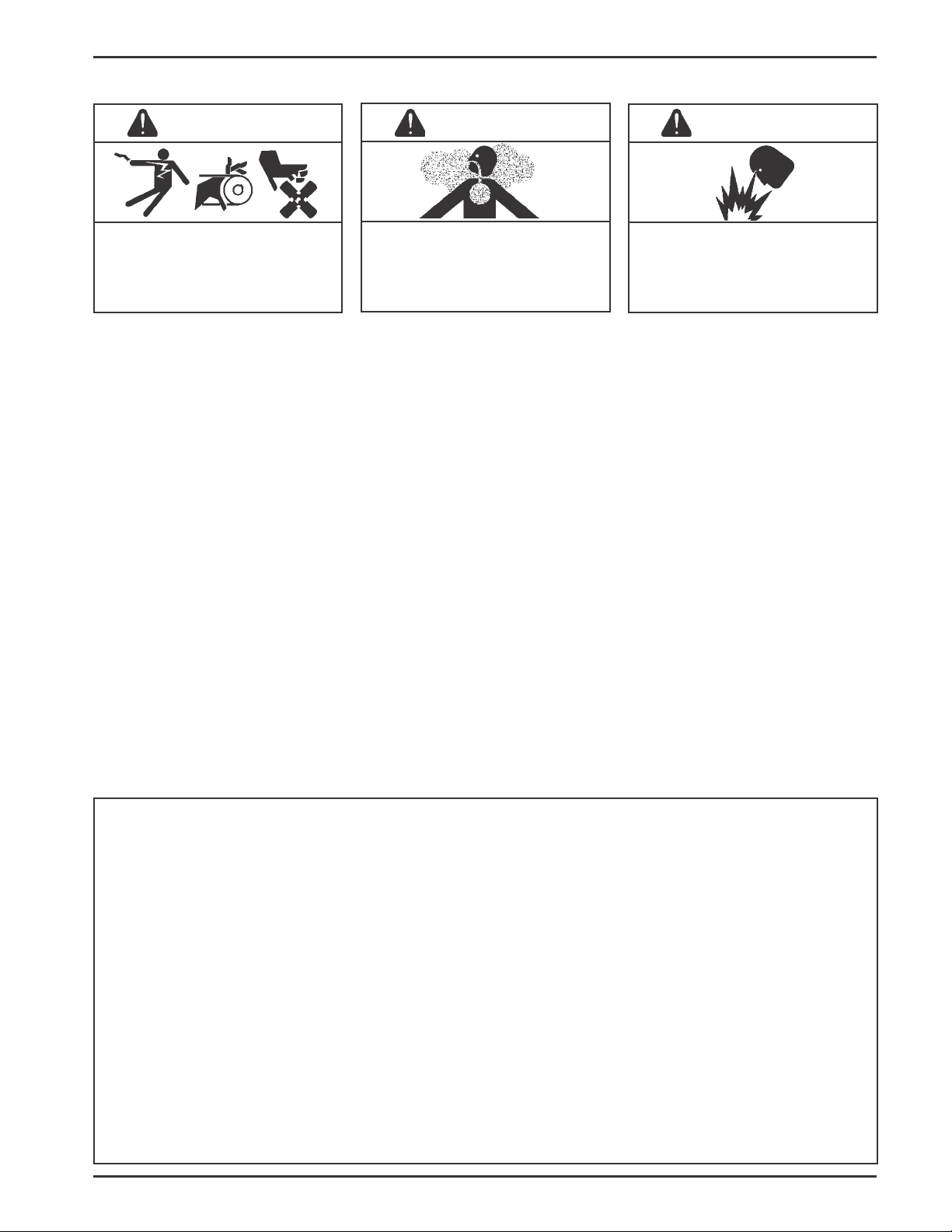
WARNING
Accidental Starts can cause severe
injury or death.
Disconnect and ground spark plug
lead before servicing.
Accidental St arts!
Disabling engine. Accidental
starting can cause severe injury or
death. Before working on the engine
or equipment, disable the engine as
follows: 1) Disconnect the spark
plug lead(s). 2) Disconnect negative
(-) battery cable from battery .
WARNING
Carbon Monoxide can cause
severe nausea, fainting or death.
Avoid inhaling exhaust fumes, and
never run the engine in a closed
building or confined area.
Lethal Exhaust Gases!
Engine exhaust gases contain
poisonous carbon monoxide.
Carbon monoxide is odorless,
colorless, and can cause death if
inhaled. Avoid inhaling exhaust
fumes, and never run the engine in
a closed building or confined area.
WARNING
Explosive Gas can cause fires and
severe acid burns.
Charge battery only in a well
ventilated area. Keep sources of
ignition away.
Explosive Gas!
Batteries produce explosive
hydrogen gas while being charged.
To prevent a fire or explosion, charge
batteries only in well ventilated
areas. Keep sparks, open flames,
and other sources of ignition away
from the battery at all times. Keep
batteries out of the reach of children.
Remove all jewelry when servicing
batteries.
Before disconnecting the negative (-)
ground cable, make sure all switches
are OFF. If ON, a spark will occur at
the ground cable terminal which
could cause an explosion if hydrogen
gas or gasoline vapors are present.
Congratulations – You have selected a fine four-cycle, single cylinder, air-cooled engine. Kohler designs long
life strength and on-the-job durability into each engine…making a Kohler engine dependable…dependability you
can count on. Here are some reasons why:
• Efficient overhead valve design and full pressure lubrication provide maximum power, torque, and reliability
under all operating conditions.
• Dependable, maintenance free electronic ignition ensures fast, easy starts time after time.
• Kohler engines are easy to service. All routine service areas (like the dipstick and oil fill, oil filter , air cleaner,
spark plug, and carburetor) are easily and quickly accessible.
• Parts subject to the most wear and tear (like the cylinder liner and camshaft) are made from precision
formulated cast iron. Because the cylinder liner can be rebored, these engines can last even longer.
• Every Kohler engine is backed by a worldwide network of over 10,000 distributors and dealers. Service
support is just a phone call away . Call 1-800-544-2444 (U.S. & Canada) for Sales & Service assist ance.
To keep your engine in top operating condition, follow the maintenance procedures in this manual.
3
Page 4
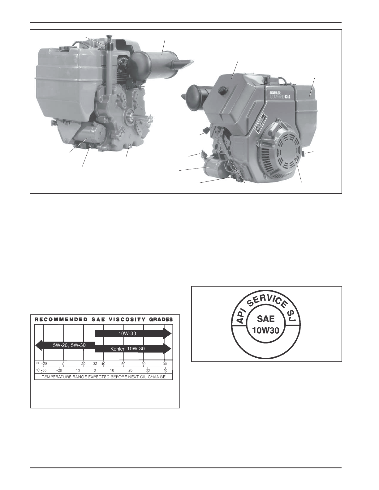
Oil Fill/Dipstick
Muffler
Air Cleaner
Fuel Tank
Choke Lever
Electric Starter
Oil Drain Plug
Oil Drain Plug
Oil Sentry
(Optional)
Oil Filter
Oil Drain Plug
Figure 1. T ypical Command Horizont al Shaft Engine.
Oil Recommendations
Using the proper type and weight of oil in the
crankcase is extremely important. So is checking oil
daily and changing oil regularly . Failure to use the
correct oil, or using dirty oil, causes premature engine
wear and failure.
Oil T ype
Use high quality detergent oil of API (American
Petroleum Institute) service class SG, SH, SJ or
higher. Select the viscosity based on the air
temperature at the time of operation as shown in the
following table.
™
Fuel
Shut-Off
Throttle Lever
Retractable St arter
NOTE: Synthetic oils meeting the listed classifications
may be used with oil changes performed at
the recommended intervals. However to allow
piston rings to properly seat, a new or rebuilt
engine should be operated for at least 50
hours using standard petroleum based oil
before switching to synthetic oil.
A logo or symbol on oil cont ainers identifies the API
service class and SAE viscosity grade. See Figure 3.
**
*Use of synthetic oil having 5W-20 or 5W-30 rating is acceptable,
up to 4°C (40°F).
**Synthetic oils will provide better starting in extreme cold below
23°C (-10°F).
*
Figure 2. Viscosity Grades Table.
NOTE: Using other than service class SG, SH, SJ or
higher oil or extending oil change intervals
longer than recommended can cause engine
damage.
4
Figure 3. Oil Container Logo.
Refer to “Maintenance Instructions” beginning on
page 8 for detailed oil check, oil change, and oil
filter change procedures.
Page 5
Fuel Recommendations
WARNING: Explosive Fuel!
Gasoline is extremely flammable and its vapors can
explode if ignited. Store gasoline only in approved
containers, in well ventilated, unoccupied buildings,
away from sparks or flames. Do not fill the fuel tank
while the engine is hot or running, since spilled fuel
could ignite if it comes in contact with hot parts or
sparks from ignition. Do not start the engine near
spilled fuel. Never use gasoline as a cleaning agent.
General Recommendations
Purchase gasoline in small quantities and store in
clean, approved containers. A cont ainer with a capacity
of 2 gallons or less with a pouring spout is
recommended. Such a container is easier to handle
and helps eliminate spillage during refueling.
Do not use gasoline left over from the previous season,
to minimize gum deposits in your fuel system and to
ensure easy starting.
Do not add oil to the gasoline.
Do not overfill the fuel tank. Leave room for the fuel to
expand.
The engine identification numbers appear on a decal
affixed to the engine shrouding. Include letter suffixes,
if there are any .
Record your engine identification numbers on the
identification label (Figure 4) for future reference.
Engines without fuel tank.
IMPORTANT ENGINE INFORMATION
THIS ENGINE MEETS U.S. EPA AND CA 2005
AND LATER AND EC STAGE II (SN:4) EMISSION
REGS FOR SI SMALL OFF–ROAD ENGINES
FAMILY
TYPE APP
DISPL. (CC)
MODEL NO.
N11236
SPEC. NO.
SERIAL NO.
BUILD DA TE
OEM PROD. NO.
EMISSION COMPLIANCE PERIOD:
EPA: CARB:
CERTIFIED ON:
REFER TO OWNER'S MANUAL FOR HP RATING,
SAFETY, MAINTENANCE AND ADJUSTMENTS
1-800-544-2444 www.kohlerengines.com
KOHLER CO. KOHLER, WISCONSIN USA
Fuel T ype
For best results use only clean, fresh, unleaded
gasoline with a pump sticker octane rating of 87 or
higher. In countries using the Research method, it
should be 90 octane minimum.
Unleaded gasoline is recommended as it leaves less
combustion chamber deposits. Leaded gasoline may
be used in areas where unleaded is not available and
exhaust emissions are not regulated. Be aware
however, that the cylinder head will require more
frequent service.
Gasoline/Alcohol blends
Gasohol (up to 10% ethyl alcohol, 90% unleaded
gasoline by volume) is approved as a fuel for Kohler
engines. Other gasoline/alcohol blends are not
approved.
Gasoline/Ether blends
Methyl Tertiary Butyl Ether (MTBE) and unleaded
gasoline blends (up to a maximum of 15% MTBE by
volume) are approved as a fuel for Kohler engines.
Other gasoline/ether blends are not approved.
Engine Identification Numbers
When ordering parts, or in any communication
involving an engine, always give the Model,
Specification, and Serial Numbers of the engine.
Engines with fuel tank supplied.
IMPORTANT ENGINE INFORMATION
THIS ENGINE MEETS U.S. EPA 2005, CA 2006 EXH/
EVP AND EC ST AGE II (SN:4) EMISSION REGS FOR
SI SMALL OFF–ROAD ENGINES
FAMILY
TYPE APP
DISPL. (CC)
MODEL NO.
N11236
SPEC. NO.
SERIAL NO.
BUILD DA TE
OEM PROD. NO.
EMISSION COMPLIANCE PERIOD:
EPA: CARB:
CERTIFIED ON:
REFER TO OWNER'S MANUAL FOR HP RATING,
SAFETY, MAINTENANCE AND ADJUSTMENTS
1-800-544-2444 www.kohlerengines.com
KOHLER CO. KOHLER, WISCONSIN USA
Figure 4. Engine Identification Label.
The Emission Compliance Period referred to on the
Emission Control or Air Index label indicates the
number of operating hours for which the engine has
been shown to meet Federal and CARB emission
requirements. The following table provides the Engine
Compliance Period (in hours) associated with the
category descriptor found on the certification label.
5
Page 6

Emission Compliance Period (Hours)
EPA
CARB
Category C
250 Hours
Moderate
125 Hours
Category B
500 Hours
Intermediate
250 Hours
Category A
1000 Hours
Extended
500 Hours
Operating Instructions
Also read the operating instructions of the equipment this engine powers.
Pre-Start Checklist
• Check oil level. Add oil if low . Do not overfill.
• Check fuel level. Add fuel if low.
Refer to certification label for engine displacement.
Exhaust Emission Control System for models
CH1 1,12.5,13,14,15,16 is EM.
Choke
Off — On
• Check cooling air intake areas and external
surfaces of engine. Make sure they are clean and
unobstructed.
• Check that the air cleaner components and all
shrouds, equipment covers, and guards are in
place and securely fastened.
• Check that any clutches or transmissions are
disengaged or placed in neutral. This is especially
important on equipment with hydrostatic drive. The
shift lever must be exactly in neutral to prevent
resistance which could keep the engine from
starting.
WARNING: Lethal Exhaust Gases!
Engine exhaust gases contain poisonous carbon
monoxide. Carbon monoxide is odorless, colorless,
and can cause death if inhaled. Avoid inhaling exhaust
fumes, and never run the engine in a closed building or
confined area.
Cold Weather Starting Hints
1. Be sure to use the proper oil for the temperature
expected. See Figure 2 on page 4.
2. Declutch all possible external loads.
3. A warm battery has much more starting cap acity
than a cold battery .
4. Use fresh winter grade fuel. NOTE: Winter grade
gasoline has higher volatility to improve starting.
Do not use gasoline left over from summer.
Starting
1. For a Cold Engine – Place the throttle control
midway between the “slow” and “fast” positions.
Place the choke control into the “on” position.
For a Warm Engine (normal operating
temperatures) – Place the throttle/choke control
midway between the “slow” and “fast”
positions. Place the choke into the “on” position.
See Figure 5.
Throttle
Fast
On
Figure 5. Throttle and Choke Positions for Starting
Engine.
2. Start the engine as follows:
For a Retractable Start Engine – SLOWLY pull
the starter handle until just past compression –
STOP! Return starter handle, pull firmly with a
smooth, steady motion to start. Pull the handle
straight out to avoid excessive rope wear from the
starter rope guide.
Extend the starting rope periodically and check its
condition. If the rope is frayed, have it replaced
immediately by your Kohler Engine Service
Dealer.
WARNING: Accidental St arts!
Before extending and checking the retractable starter
rope, remove the spark plug lead to prevent the engine
from starting accidentally. Make sure the equipment is
in neutral.
For an Electric Start Engine – Activate the
starter switch. Release the switch as soon as the
engine starts.
NOTE: Do not crank the engine continuously for
more than 10 seconds at a time. If the
engine does not start, allow a 60 second
cool down period between starting
attempts. Failure to follow these
guidelines can burn out the starter motor .
6
Page 7

NOTE: Upon start-up, a metallic ticking may
occur. This is caused by hydraulic lifter
leakdown during storage. Run the engine
for 5 minutes. The noise will normally
cease in the first minute. If noise
continues, run the engine at mid-throttle
for 20 minutes. If noise persists, take the
engine to your local Kohler Service outlet.
b. For engines equipped with a shutdown
solenoid: Position the throttle control somewhere
between half and full throttle; then stop the engine.
Battery
A 12 volt battery is normally used. Refer to the operating
instructions of the equipment this engine powers for
specific battery requirements.
NOTE: If the engine develops sufficient speed to
disengage the starter but does not keep
running (a false start), engine rotation
must be allowed to come to a complete
stop before attempting to restart the
engine. If the starter is engaged while the
flywheel is rotating, the starter pinion and
flywheel ring gear may clash, resulting in
damage to the starter .
If the starter does not turn the engine over , shut
off starter immediately. Do not make further
attempts to start the engine until the condition is
corrected. Do not jump start using another battery
(refer to “Battery”). See your Kohler Engine
Service Dealer for trouble analysis.
3. For a Cold Engine – Gradually return the choke
control to the “off” position after the engine starts
and warms ups.
The engine/equipment may be operated during
the warm up period, but it may be necessary to
leave the choke partially on until the engine warms
up.
4. For a Warm Engine – Return choke to “off”
position as soon as engine starts.
If the battery charge is not sufficient to crank the engine,
recharge the battery (see page 12).
Operating
Angle of Operation
This engine will operate continuously at angles up to
25°. Check oil level to assure crankcase oil level is at
the “F” mark.
Refer to the operating instructions of the equipment this
engine powers. Because of equipment design or
application, there may be more stringent restrictions
regarding the angle of operation.
NOTE: Do not operate this engine continuously at
angles exceeding 25° in any direction. Engine
damage could result from insufficient
lubrication.
Cooling
NOTE: If debris builds up on the grass screen or other
cooling air intake areas, stop the engine
immediately and clean. Operating the engine
with blocked or dirty air intake and cooling
areas can cause extensive damage due to
overheating.
Stopping
1. Remove the load by disengaging all PTO
attachments.
2a. For engines without a shutdown solenoid:
Move the throttle to the ‘‘slow’’ or ‘‘low’’ idle
position. Allow the engine to run at idle for 30-60
seconds; then stop the engine.
Engine components can get extremely hot from
operation. T o prevent severe burns, do not touch these
areas while the engine is running–or immediately after it
is turned off. Never operate the engine with heat
shields or guards removed.
Engine Speed
NOTE: Do not tamper with the governor setting to
WARNING: Hot Parts!
increase the maximum engine speed.
Overspeed is hazardous and will void the
engine warranty .
Maintenance Instructions
Maintenance, repair, or replacement of the emission control devices and systems, which are being done
at the customers expense, may be performed by any non-road engine repair establishment or individual.
Warranty repairs must be performed by an authorized Kohler service outlet.
WARNING: Accidental Starts!
Disabling engine. Accidental starting can cause severe injury or death. Before working on the engine or equipment, disable the engine as follows: 1) Disconnect the spark plug lead(s). 2) Disconnect negative (-) battery cable
from battery .
7
Page 8

Maintenance Schedule
These required maintenance procedures should be performed at the frequency stated in the table. They should also
be included as part of any seasonal tune-up.
Maintenance RequiredFrequency
• Fill fuel tank.
Daily or Before
Starting Engine
Every 25 Hours
Every 50 Hours
Every 100 Hours
Every 200 Hours
Annually or
Every 500 Hours
¹Perform these maintenance procedures more frequently under extremely dusty , dirty conditions.
2
Only required for Denso starters. Not necessary on Delco starters. Have a Kohler Engine Service Dealer perform
this service.
• Check oil level.
• Check air cleaner for dirty¹, loose, or damaged parts.
• Check air intake and cooling areas, clean as necessary¹.
• Service precleaner element¹.
• Check gear reduction unit.
• Replace air cleaner element¹.
• Change oil.
• Remove cooling shrouds and clean cooling areas¹.
• Change oil filter.
• Check spark plug condition and gap.
• Replace fuel filter.
• Have bendix starter drive serviced².
• Have solenoid shift starter disassembled and cleaned2.
Check Oil Level
The importance of checking and maintaining the proper
oil level in the crankcase cannot be overemphasized.
Check oil BEFORE EACH USE as follows:
1. Make sure the engine is stopped, level, and is cool
so the oil has had time to drain into the sump.
2. To keep dirt, grass clippings, etc., out of the
engine, clean the area around the oil fill cap/
dipstick before removing it.
3. Remove the oil fill cap/dipstick; wipe oil off.
For engines with a press-on style dipstick:
Reinsert the dipstick into the tube and press onto
the tube. See Figure 6.
For engines with a thread-on style dipstick:
Reinsert the dipstick into the tube and rest the oil
fill cap on the tube. Do not thread the cap onto the
tube. See Figure 6.
4. Remove the dipstick and check the oil level.
The oil level should be up to, but not over, the “F”
mark on the dipstick. See Figure 7.
“F” Mark
Operating
Range
Figure 7. Oil Level Dipstick.
5. If the level is low , add oil of the proper type, up to
the “F” mark on the dipstick. (Refer to “Oil T ype” on
page 4.) Always check the level with the dip stick
before adding more oil.
NOTE: T o prevent extensive engine wear or
damage, always maintain the proper oil
level in the crankcase. Never operate the
engine with the oil level below the “L”
mark or over the “F” mark on the dipstick.
Press-On
Figure 6. Dipstick Styles.
8
Thread-On
Page 9

Oil Sentry
™
Some engines are equipped with an optional Oil
Sentry™ oil pressure switch. If the oil pressure
decreases below an acceptable level, the Oil Sentry
will either shut off the engine or activate a warning
signal, depending on the application.
NOTE: Make sure the oil level is checked BEFORE
EACH USE and is maintained up to the “F”
mark on the dipstick. This includes engines
equipped with Oil Sentry™.
Change Oil and Oil Filter
™
Oil
Sentry
™
(Optional)
Change Oil
Change oil after every 100 hours of operation. Refill
with service class SG, SH, SJ or higher oil as specified
in the “Viscosity Grades” table (Figure 2) on page 4.
Change the oil while the engine is still warm. The oil
will flow more freely and carry away more impurities.
Make sure the engine is level when filling, checking, or
changing the oil.
Change the oil as follows (see Figure 8):
1. To keep dirt, grass clippings, etc., out of the
engine, clean the area around the oil fill cap/
disptick before removing it.
2. Remove the oil drain plug and oil fill cap/dipstick.
Be sure to allow ample time for complete
drainage.
3. Reinstall the drain plug. Make sure it is tightened
to 13.6 N·m (10 ft. lb.) torque.
4. Fill the crankcase, with new oil, of the proper type,
to the “F” mark on the dipstick. Refer to “Oil Type”
on page 4. Always check the level with the dipstick
before adding more oil.
5. Reinstall the oil fill cap or plug and tighten
securely .
NOTE: To prevent extensive engine wear or
damage, always maintain the proper oil
level in the crankcase. Never operate the
engine with the oil level below the “L”
mark or over the “F” mark on the dipstick.
Oil Filter
Figure 8. Oil Filter and Optional Oil Sentry
™
Switch.
Change Oil Filter
Replace the oil filter at least every other oil change
(every 200 hours of operation). Always use a genuine
Kohler oil filter. Use chart below to determine p art
number to order.
Oil Filter Part No.
12 050 01-S
52 050 02-S
Length
2-1/2"
3-3/8"
Replace the oil filter as follows:
1. Drain the oil from the engine crankcase.
2. Allow the oil filter to drain.
3. Before removing the oil filter, clean the area
around the oil filter to keep dirt and debris out of
the engine. Remove the old filter. Wipe of f the
surface where the oil filter mounts.
4. Place a new replacement filter in a shallow pan
with the open end up. Pour new oil of the proper
type in through the threaded center hole. Stop
pouring when the oil reaches the bottom of the
threads. Allow a minute or two for the oil to be
absorbed by the filter material.
5. Apply a thin film of clean oil to the rubber gasket
on the new filter.
6. Install the replacement oil filter to the filter adapter .
Turn the oil filter clockwise until the rubber gasket
contacts the filter adapter , then tighten the filter an
additional 3/4 to 1 turn.
7. Reinstall the drain plug.
8. Fill the crankcase with new oil of the proper type to
the ‘‘F’’ mark on the dipstick.
9
Page 10

9. S tart the engine and check for oil leaks. Correct
any leaks before placing the engine into service.
Check oil level to be sure it is up to but not over
the “F” mark.
Service Precleaner and Air Cleaner Element
This engine is equipped with a replaceable, high
density paper air cleaner element. Most engines are
also equipped with an oiled, foam precleaner which
surrounds the paper element. See Figures 9 and 10.
2. Remove the precleaner from the paper element.
3. Wash the precleaner in warm water with detergent.
Rinse the precleaner thoroughly until all traces of
detergent are eliminated. Squeeze out excess
water (do not wring). Allow precleaner to air dry .
4. Saturate the precleaner with new engine oil.
Squeeze out all excess oil.
5. Reinstall the precleaner over the paper element.
Air Cleaner
Cover
Knob
Figure 9. Air Cleaner Housing Components.
Air Cleaner Base
Element Cover Nut
Paper
Element
Element
Cover
Foam Precleaner
Figure 10. Air Cleaner Elements.
Check the air cleaner daily or before starting the
engine. Check for a buildup of dirt and debris around
the air cleaner system. Keep this area clean. Also
check for loose or damaged components. Replace all
bent or damaged air cleaner components.
6. Reinstall the air cleaner cover and tighten the
knob securely .
7. When precleaner replacement is necessary order
Part No. 52 083 01-S.
Service Paper Element
Every 100 hours of operation (more often under
extremely dusty or dirty conditions), replace the paper
element.
1. Loosen the air cleaner cover knob and remove the
cover. Remove the wing nut and then remove the air
cleaner element with precleaner. Remove the
precleaner from the element and service as
necessary.
2. Do not wash the paper element or use
pressurized air, as this will damage the element.
Replace a dirty , bent, or damaged element with a
genuine Kohler element. Handle new elements
carefully; do not use if the sealing surfaces are
bent or damaged.
3. When servicing the air cleaner, check the air
cleaner base. Make sure it is secured and not
bent or damaged. Also check the element cover
for damage or improper fit. Replace all damaged
air cleaner components.
4. Reinstall all components as described above.
5. When air cleaner element replacement is
necessary order Part No. 47 083 01-S.
NOTE: Operating the engine with loose or damaged air
cleaner components could allow unfiltered air
into the engine causing premature wear and
failure.
Service Precleaner
Wash and reoil the precleaner every 25 hours of
operation, (more often under extremely dusty or dirty
conditions).
1. Loosen the air cleaner cover knob and remove the
cover.
10
Clean Air Intake/Cooling Areas
T o ensure proper cooling, make sure the grass screen,
cooling fins, and other external surfaces of the engine
are kept clean at all times.
Every100 hours of operation (more often under
extremely dusty , dirty conditions), remove the blower
housing and other cooling shrouds. Clean the cooling
fins and external surfaces as necessary . Make sure the
cooling shrouds are reinstalled.
Page 11

NOTE: Operating the engine with a blocked grass
screen, dirty or plugged cooling fins, and/or
cooling shrouds removed, will cause engine
damage due to overheating.
Ignition System
This engine is equipped with a dependable electronic
magneto ignition system. Other than periodically
checking/replacing the spark plug, no maintenance,
timing, or adjustments are necessary or possible with
this system.
In the event starting problems should occur which are not
corrected by replacing the spark plugs, see your Kohler
Engine Service Dealer for trouble analysis.
Check Spark Plug
Every200 hours of operation, remove the spark plug,
check its condition, and reset the gap or replace with a
new plug as necessary . The standard sp ark plug is a
Champion® RC12YC (Kohler Part No. 12 132 02-S). A
high-performance spark plug, Champion®Platinum 3071
(used on Pro Series engines, Kohler Part No.
25 132 12-S), is also available. Equivalent alternate
brand plugs can also be used.
1. Before removing the spark plug, clean the area
around the base of the plug to keep dirt and debris
out of the engine.
2. Remove the plug and check its condition. Replace
the plug if worn or reuse is questionable.
4. Reinstall the spark plug into the cylinder head.
T orque the spark plug to 38.0-43.4 N·m
(28-32 ft. lb.).
Battery Charging
WARNING: Explosive Gas!
Batteries produce explosive hydrogen gas while being
charged. T o prevent a fire or explosion, charge batteries
only in well ventilated areas. Keep sparks, open flames,
and other sources of ignition away from the battery at all
times. Keep batteries out of the reach of children.
Remove all jewelry when servicing batteries.
Before disconnecting the negative (-) ground cable,
make sure all switches are OFF. If ON, a spark will occur
at the ground cable terminal which could cause an
explosion if hydrogen gas or gasoline vapors are present.
Fuel Filter
Most engines are equipped with an in-line fuel filter.
Periodically inspect the filter and replace with a genuine
Kohler filter every 200 operating hours.
Fuel Line
In compliance with CARB Tier III Emission Regulations,
these engines with a “Family” identification number
beginning with “6” or greater (see Figure 12), must use
Low Permeation SAE 30 R7 rated fuel line; certified to
meet CARB requirements. St andard fuel line may not be
used. Order replacement hose by part number through a
Kohler Engine Service Dealer.
NOTE: Do not clean the spark plug in a machine
using abrasive grit. Some grit could remain
in the spark plug and enter the engine
causing extensive wear and damage.
3. Check the gap using a wire feeler gauge. Adjust
the gap by carefully bending the ground electrode.
See Figure 1 1. Gap CH1 1-15 plugs to 1.02 mm
(0.040 in.). Gap CH16 plugs to 0.76 mm (0.030 in.).
Wire Gauge
Spark Plug
Ground
Electrode
Gap
Figure 11. Servicing Spark Plug.
IMPORTANT ENGINE INFORMATION
THIS ENGINE MEETS U.S. EP A AND CA 2005 AND
LA TER AND EC ST AGE II (SN:4) EMISSION REGS
FOR SI SMALL OFF–ROAD ENGINES
FAMILY 6 KHXS.XXXXGC
TYPE APP
DISPL. (CC)
MODEL NO.
N1 1236
SPEC. NO.
SERIAL NO.
BUILD DA TE
OEM PROD. NO.
EMISSION COMPLIANCE PERIOD:
EPA: CARB:
CERTIFIED ON:
REFER TO OWNER'S MANUAL FOR HP RA TING ,
SAFETY , MAINTENANCE AND ADJUSTMENTS
1-800-544-2444 www.kohlerengines.com
KOHLER CO. KOHLER, WISCONSIN USA
Figure 12. “Family” Number Location.
11
Page 12

Reduction Gear Units
On engines equipped with a reduction gear unit, remove
the oil plug on lower part of cover every 50 hours of
operation to check oil level. With the engine level, the oil
level of the unit should be up to the bottom of the oil plug
hole. T o add oil, remove the vented plug at the top of the
unit. Use AGMA No. 7 EP oil in the reduction gear unit.
Following are a few products that meet this spec:
Mobilgear 634
Pennzoil Super Maxol ‘‘S’’
Pennzoil Maxol EP Gear Oil
Pennzoil Super Maxol EP Gear Oil
Pennzoil Super Pennztac EP Gear Oil
NOTE: T o ensure correct engine operation at altitudes
above 1525 meters (5000 ft.), it may be
necessary to have an authorized Kohler dealer
install a special high-altitude jet kit in the
carburetor. If a high-altitude kit has been
installed, the engine must be reconverted to
the original jet size, before it is operated at
lower altitudes, or overheating and engine
damage can result.
Troubleshooting
If engine troubles are experienced that appear to be fuel
system related, check the following areas before
adjusting the carburetor.
Carburetor Troubleshooting
and Adjustments
NOTE: Carburetor adjustments should be made only
after the engine has warmed up.
These engines are equipped with one of two basic types
of fixed jet carburetors – Walbro or Nikki.
The carburetor is designed to deliver the correct
fuel-to-air mixture to the engine under all operating
conditions. On both types of carburetors, the fixed main
jet is calibrated at the factory and is not adjustable. On
Walbro carburetors, the low idle fuel adjusting needle is
set at the factory and normally does not need
adjustment. Certified engines may have a fixed idle or
limiter cap on the idle fuel adjusting needle. The idle
fuel can only be adjusted within the limits allowed by the
cap. Nikki carburetors have a sealed idle fuel adjusting
needle which is not adjustable.
Walbro
Low Idle
Speed Adj.
Screw
Low Idle
Fuel Adj.
Needle
• Make sure the fuel tank is filled with clean, fresh
gasoline.
• Make sure the fuel tank cap vent is not blocked
and that it is operating properly .
• If the fuel tank is equipped with a shut-off valve,
make sure it is open.
• If the engine is equipped with an in-line fuel filter,
make sure it is clean and unobstructed. Replace
the filter if necessary .
• Make sure fuel is reaching the carburetor. This
includes checking the fuel lines and fuel pump for
restrictions or faulty components, replace as
necessary .
• Make sure the air cleaner element is clean and all
air cleaner components are fastened securely .
If, after checking the items listed above, the engine is
hard to start, runs roughly , or st alls at low idle speed, it
may be necessary to adjust or service the carburetor.
Carburetor Adjustment
NOTE: Certified engines may have a fixed idle or
limiter cap on the idle fuel adjusting needle.
Step 2 can only be performed within the limit s
allowed by the cap.
Nikki
Low Idle
Speed Adj.
Screw
Figure 13. Carburetors.
12
1. S tart the engine and run at half throttle for 5 to 10
minutes to warm up. The engine must be warm
before doing steps 2 and 3.
2. Low Idle Fuel Needle Setting: Place the throttle
into the “idle” or “slow” position.
Turn the low idle fuel adjusting needle out
(counterclockwise) from the preliminary setting
until engine speed decreases (rich). Note the
position of the needle.
Page 13

Now turn the adjusting needle in (clockwise). The
engine speed may increase, then it will decrease
as the needle is turned in (lean). Note the position
of the needle.
3. Low Idle Speed Setting: Place the throttle
control into the “idle” or “slow” position. Set the
low idle speed to 1200 RPM* (± 75 RPM) by
turning the low idle speed adjusting screw in or
out. Check the speed using a tachometer .
Set the adjusting needle midway between the rich
and lean settings. See Figure 14.
*NOTE: The actual low idle speed depends on the
application – refer to equipment
Adjust to
Midpoint
Lean
manufacturer’s recommendations. The
recommended low idle speed for basic
engines is 1200 RPM. To ensure best
results when setting the low idle fuel
needle, the low idle speed must not
exceed 1200 RPM (± 75 RPM).
Rich
Figure 14. Optimum Low Idle Fuel Setting.
Troubleshooting
When troubles occur, be sure to check the simple causes which, at first, may seem to obvious to be considered.
For example, a starting problem could be caused by an empty fuel tank. Some common causes of engine troubles
are listed in the following table.
Do not attempt to service or replace major engine components, or any items that require special timing or
adjustment procedures. Have your Kohler Engine Service Dealer do this work.
Possible Cause No Improper Dirt In Dirty Incorrect Engine Dirty Air Faulty
Problem Fuel Fuel Fuel Line/SystemGrass Screen Oil Level Overloaded Cleaner Spark Plug
Will Not Start ••• ••••
Hard Starting •• ••••
Stops Suddenly • •••••
Lacks Power •••••••
Operates Erratically ••• • ••
Knocks or Pings •• • •
Skips or Misfires ••• ••
Backfires ••••
Overheats •••••
High Fuel Consumption •••
13
Page 14

Storage
If the engine will be out of service for two months or
more, use the following storage procedure:
Parts Ordering
The engine Model, Specification, and Serial Numbers
are required when ordering replacement parts from your
Kohler Engine Service Dealer. These numbers are found
1. Clean the exterior surfaces of the engine.
on the identification plate which is affixed to the engine
shrouding. Include letter suffixes if there are any . See
2. Change the oil and filter while the engine is still
“Engine Identification Numbers” on page 5.
warm from operation. See “Change Oil and Oil
Filter” on page 9.
Always insist on genuine Kohler parts. All genuine
Kohler parts meet strict standards for fit, reliability, and
3. The fuel system must be completely emptied, or
performance.
the gasoline must be treated with a stabilizer to
prevent deterioration. If you choose to use a
stabilizer, follow the manufacturers
recommendations, and add the correct amount for
the capacity of the fuel system. Fill the fuel tank
with clean, fresh gasoline. Run the engine for 2-3
minutes to get stabilized fuel into the carburetor .
Major Repair
Major repair information is available in Kohler Engine
Service Manuals. However, major rep air generally
requires the attention of a trained mechanic and the
use of special tools and equipment. Your Kohler
Engine Service Dealer has the facilities, training, and
genuine Kohler replacement parts necessary to
To empty the system, run the engine until the fuel
tank and system are empty.
perform this service. For Sales & Service assistance
call 1-800-544-2444 (U.S. & Canada) or contact your
Kohler Engine Dealer or Service Distributor, they're in
4. Remove the spark plug. Add one tablespoon of
the Y ellow Pages under Engines-Gasoline.
engine oil into the spark plug hole. Install the plug,
but do not connect the plug lead. Crank the engine
two or three revolutions.
5. Remove the spark plug. Cover the spark plug hole
with your thumb, and turn the engine over until the
piston is at the top of its stroke. (Pressure against
thumb is greatest.) Reinstall the plug, but do not
connect the plug lead.
6. S tore the engine in a clean, dry place.
Model Designation
Model CH15ST for example: C designates Command
engine, H designates horizontal crankshaft, and 15
designates horsepower. A letter suffix designates a
specific version as follows:
Suffix Designates
S Electric Start
T Retractable Start
ST Electric/Retractable Start
G T Generator Application/Retractable Start
GS Generator Application/Electric St art
PT Pump/Retractable Start
RT Gear Reduction/Retractable St art
Specifications
Model: ..................................................CH11 ............. CH12.5 ...........CH13 ..............CH14.............. CH15/CH16**
Bore: ................................. mm (in.) ... 87 (3.43) ........ 87 (3.43) .........87 (3.43) ......... 87 (3.43) ......... 90 (3.55)/90 (3.55)
Stroke: ............................... mm (in.) ...67 (2.64) ........ 67 (2.64) ......... 67 (2.64) .........67 (2.64)......... 67 (2.64)/67 (2.64)
Displacement: ..................cm3 (in3) ... 398 (24.3) ...... 398 (24.3) ....... 398 (24.3) ....... 398 (24.3) ....... 426 (26.0)/426 (26.0)
Power (@3600 RPM):....... kW (HP) ...8.2 (11*) ......... 9.33 (12.5*).....9.75 (13*) ....... 10.50 (14*) ..... 11.2 (15*)/11.9 (16*)
Max. Peak Torque (@ RPM): ... ft. lb. ... 19.7 @2400 ... 20.5 @2500 ....21.1 @2200 ... 21.3 @2500 ... 24.8 @2400/25.3 @2400
Compression Ratio: ............................8.5:1............... 8.5:1................ 8.5:1 ............... 8.5:1 ............... 8.5:1/8.5:1
Weight:.................................kg (lb.) ...40 (88.3) ........ 40 (88.3) ......... 40 (88.3) .........40 (88.3)......... 40 (88.3)/40 (88.3)
Oil Capacity (w/filter):.....L (U.S. qt.) ...1.9 (2) ............ 1.9 (2) .............1.9 (2) ............. 1.9 (2) ............. 1.9 (2)/1.9 (2)
Lubrication: .......................................... Full Pressure w/full Flow Filter
Exhaust Emission Control System for CH11,12.5,13,14,15,16 is EM.
*Horsepower ratings exceed Society of Automotive Engineers Small Engine Test Code J1940.
Actual engine horsepower is lower and affected by, but not limited to, accessories (air cleaner, exhaust, charging, cooling,
fuel pump, etc.), application, engine speed and ambient operating conditions (temperature, humidity, and altitude). Kohler
reserves the right to change product specifications, designs and equipment without notice and without incurring
obligation.
**CH16 engine is equipped with SMART-SPARK
computerized ignition system.
™
14
Page 15

LIMITED 2 YEAR COMMAND ENGINE W ARRANTY
Kohler Co. warrants to the original consumer that each new COMMAND engine sold by Kohler Co. will be free from manufacturing defects
in materials or workmanship in normal service for a period of two (2) years from date of purchase, provided it is operated and maintained
in accordance with Kohler Co.’s instructions and manuals.
Our obligation under this warranty is expressly limited, at our option, to the replacement or repair at Kohler Co., Kohler, Wisconsin 53044,
or at a service facility designated by us of such parts as inspection shall disclose to have been defective.
EXCLUSIONS:
Mufflers on engines used commercially (non-residential) are warranted for one (1) year from date of purchase, except catalytic mufflers,
which are warranted for two (2) years.
This warranty does not apply to defects caused by casualty or unreasonable use, including faulty repairs by others and failure to provide
reasonable and necessary maintenance.
The following items are not covered by this warranty:
Engine accessories such as fuel tanks, clutches, transmissions, power-drive assemblies, and batteries, unless supplied or installed by
Kohler Co. These are subject to the warranties, if any, of their manufacturers.
KOHLER CO. AND/OR THE SELLER SHALL NOT BE LIABLE FOR SPECIAL, INDIRECT, INCIDENTAL, OR CONSEQUENTIAL
DAMAGES OF ANY KIND, including but not limited to labor costs or transportation charges in connection with the repair or replacement
of defective parts.
IMPLIED OR STATUTORY WARRANTIES, INCLUDING WARRANTIES OF MERCHANTABILITY OR FITNESS FOR A PARTICULAR
PURPOSE, ARE EXPRESSLY LIMITED TO THE DURATION OF THIS WRITTEN WARRANTY. We make no other express warranty, nor
is any one authorized to make any on our behalf.
Some states do not allow limitations on how long an implied warranty lasts, or the exclusion or limitation of incidental or consequential
damages, so the above limitation or exclusion may not apply to you.
This warranty gives you specific legal rights, and you may also have other rights which vary from state to state.
TO OBTAIN WARRANTY SERVICE:
Purchaser must bring the engine to an authorized Kohler service facility. To locate the nearest facility, visit our website,
www.kohlerengines.com, and click on SALES AND SERVICES to use the locator function, consult your Yellow Pages or telephone
1-800-544-2444.
ENGINE DIVISION, KOHLER CO., KOHLER, WISCONSIN 53044
KOHLER CO.
FEDERAL AND CALIFORNIA EMISSION CONTROL SYSTEMS
LIMITED WARRANTY
SMALL OFF-ROAD ENGINES
The U.S. Environmental Protection Agency (EPA), the California Air Resources Board (CARB), and Kohler Co. are pleased to explain the
Federal and California Emission Control Systems Warranty on your small off-road equipment engine. In California beginning in 2006,
“emissions“ means both exhaust and evaporative emissions. For California, engines produced in 2006 and later must be designed, built
and equipped to meet the state’s stringent anti-smog standards. In other states, 1997 and later model year engines must be designed,
built and equipped, to meet the U.S. EPA regulations for small non-road engines. The engine must be free from defects in materials and
workmanship which cause it to fail to conform with U.S. EPA standards for the first two years of engine use from the date of sale to the
ultimate purchaser. Kohler Co. must warrant the emission control system on the engine for the period of time listed above, provided there
has been no abuse, neglect or improper maintenance.
The emission control system may include parts such as the carburetor or fuel injection system, the ignition system, and catalytic converter.
Also included are the hoses, belts and connectors and other emission related assemblies.
Where a warrantable condition exists, Kohler Co. will repair the engine at no cost, including diagnosis (if the diagnostic work is performed
at an authorized dealer), parts and labor.
MANUFACTURER’S W ARRANTY COVERAGE
Engines produced in 2006 or later are warranted for two years in California. In other states, 1997 and later model year engines are
warranted for two years. If any emission related part on the engine is defective, the part will be repaired or replaced by Kohler Co. free of
charge.
OWNER’S WARRANTY RESPONSIBILITIES
(a) The engine owner is responsible for the performance of the required maintenance listed in the owner’s manual. Kohler Co.
recommends that you retain all receipts covering maintenance on the engine, But Kohler Co. cannot deny warranty solely for the lack
of receipts or for your failure to assure that all scheduled maintenance was performed.
(b) Be aware, however, that Kohler Co. may deny warranty coverage if the engine or a part has failed due to abuse, neglect, improper
maintenance or unapproved modifications.
Continued on next page.
15
Page 16

(c) For warranty repairs, the engine must be presented to a Kohler Co. service center as soon as a problem exists. Call 1-800-544-2444,
or access our web site at: www.kohlerengines.com for the names of the nearest service centers. The warranty repairs should be
completed in a reasonable amount of time, not to exceed 30 days.
If you have any questions regarding warranty rights and responsibilities, you should contact Kohler Co. at 1-920-457-4441 and ask for an
Engine Service representative.
COVERAGE
Kohler Co. warrants to the ultimate purchaser and each subsequent purchaser that the engine will be designed, built and equipped, at the
time of sale, to meet all applicable regulations. Kohler Co. also warrants to the initial purchaser and each subsequent purchaser, that the
engine is free from defects in materials and workmanship which cause the engine to fail to conform with applicable regulations for a period
of two years.
Engines produced in 2006 or later are warranted for two years in California. For 1997 and later model years, EPA requires manufacturers
to warrant engines for two years in all other states. These warranty periods will begin on the date the engine is purchased by the initial
purchaser. If any emission related part on the engine is defective, the part will be replaced by Kohler Co. at no cost to the owner. Kohler
Co. is liable for damages to other engine components caused by the failure of a warranted part still under warranty.
Kohler Co. shall remedy warranty defects at any authorized Kohler Co. engine dealer or warranty station. Warranty repair work done at an
authorized dealer or warranty station shall be free of charge to the owner if such work determines that a warranted part is defective.
Listed below are the parts covered by the Federal and California Emission Control Systems Warranty. Some parts listed below may
require scheduled maintenance and are warranted up to the first scheduled replacement point for that part. The warranted parts are to
the extent they were present in the engine purchased:
• Oxygen sensor (if equipped) • Ignition module(s) with high tension lead
• Intake manifold (if equipped) • Gaseous fuel regulator (if equipped)
• Exhaust manifold (if equipped) • Electronic control unit (if equipped)
• Catalytic muffler (if equipped) • Carburetor or fuel injection system
• Fuel metering valve (if equipped) • Fuel lines, fuel line fittings and clamps (if equipped)
• Spark advance module (if equipped) • Air filter, fuel filter, and spark plugs (only
• Crankcase breather to first scheduled replacement point)
LIMITATIONS
This Emission Control Systems Warranty shall not cover any of the following:
(a) repair or replacement required because of misuse or neglect, improper maintenance, repairs improperly performed or replacements
not conforming to Kohler Co. specifications that adversely affect performance and/or durability and alterations or modifications not
recommended or approved in writing by Kohler Co.,
(b) replacement of parts and other services and adjustments necessary for required maintenance at and after the first scheduled
replacement point,
(c) consequential damages such as loss of time, inconvenience, loss of use of the engine or equipment, etc.,
(d) diagnosis and inspection fees that do not result in eligible warranty service being performed, and
(e) any add-on or modified part, or malfunction of authorized parts due to the use of add-on or modified parts.
MAINTENANCE AND REPAIR REQUIREMENTS
The owner is responsible for the proper use and maintenance of the engine. Kohler Co. recommends that all receipts and records covering
the performance of regular maintenance be retained in case questions arise. If the engine is resold during the warranty period, the
maintenance records should be transferred to each subsequent owner. Kohler Co. reserves the right to deny warranty coverage if the
engine has not been properly maintained; however, Kohler Co. may not deny warranty repairs solely because of the lack of repair
maintenance or failure to keep maintenance records.
Normal maintenance, replacement or repair of emission control devices and systems may be performed by any repair establishment or
individual; however, warranty repairs must be performed by a Kohler authorized service center. Any replacement part or service that is
equivalent in performance and durability may be used in non-warranty maintenance or repairs, and shall not reduce the warranty obligations
of the engine manufacturer.
FORM NO.: 12 590 02-A
ISSUED: 11/04
REVISED: 8/06
MAILED:
LITHO IN U.S.A.
FOR SALES AND SER VICE INFORMATION
IN U.S. AND CANADA, CALL 1-800-544-2444
ENGINE DIVISION, KOHLER CO., KOHLER, WISCONSIN 53044
 Loading...